EP4159606B1 - Leaning vehicle - Google Patents
Leaning vehicle Download PDFInfo
- Publication number
- EP4159606B1 EP4159606B1 EP22196649.2A EP22196649A EP4159606B1 EP 4159606 B1 EP4159606 B1 EP 4159606B1 EP 22196649 A EP22196649 A EP 22196649A EP 4159606 B1 EP4159606 B1 EP 4159606B1
- Authority
- EP
- European Patent Office
- Prior art keywords
- vehicle
- body frame
- leaning
- supported
- measurement unit
- Prior art date
- Legal status (The legal status is an assumption and is not a legal conclusion. Google has not performed a legal analysis and makes no representation as to the accuracy of the status listed.)
- Active
Links
Images




Classifications
-
- B—PERFORMING OPERATIONS; TRANSPORTING
- B62—LAND VEHICLES FOR TRAVELLING OTHERWISE THAN ON RAILS
- B62K—CYCLES; CYCLE FRAMES; CYCLE STEERING DEVICES; RIDER-OPERATED TERMINAL CONTROLS SPECIALLY ADAPTED FOR CYCLES; CYCLE AXLE SUSPENSIONS; CYCLE SIDECARS, FORECARS, OR THE LIKE
- B62K5/00—Cycles with handlebars, equipped with three or more main road wheels
- B62K5/02—Tricycles
- B62K5/027—Motorcycles with three wheels
-
- B—PERFORMING OPERATIONS; TRANSPORTING
- B60—VEHICLES IN GENERAL
- B60G—VEHICLE SUSPENSION ARRANGEMENTS
- B60G17/00—Resilient suspensions having means for adjusting the spring or vibration-damper characteristics, for regulating the distance between a supporting surface and a sprung part of vehicle or for locking suspension during use to meet varying vehicular or surface conditions, e.g. due to speed or load
- B60G17/015—Resilient suspensions having means for adjusting the spring or vibration-damper characteristics, for regulating the distance between a supporting surface and a sprung part of vehicle or for locking suspension during use to meet varying vehicular or surface conditions, e.g. due to speed or load the regulating means comprising electric or electronic elements
- B60G17/019—Resilient suspensions having means for adjusting the spring or vibration-damper characteristics, for regulating the distance between a supporting surface and a sprung part of vehicle or for locking suspension during use to meet varying vehicular or surface conditions, e.g. due to speed or load the regulating means comprising electric or electronic elements characterised by the type of sensor or the arrangement thereof
- B60G17/01908—Acceleration or inclination sensors
-
- B—PERFORMING OPERATIONS; TRANSPORTING
- B62—LAND VEHICLES FOR TRAVELLING OTHERWISE THAN ON RAILS
- B62J—CYCLE SADDLES OR SEATS; AUXILIARY DEVICES OR ACCESSORIES SPECIALLY ADAPTED TO CYCLES AND NOT OTHERWISE PROVIDED FOR, e.g. ARTICLE CARRIERS OR CYCLE PROTECTORS
- B62J45/00—Electrical equipment arrangements specially adapted for use as accessories on cycles, not otherwise provided for
- B62J45/40—Sensor arrangements; Mounting thereof
- B62J45/41—Sensor arrangements; Mounting thereof characterised by the type of sensor
- B62J45/415—Inclination sensors
- B62J45/4151—Inclination sensors for sensing lateral inclination of the cycle
-
- B—PERFORMING OPERATIONS; TRANSPORTING
- B62—LAND VEHICLES FOR TRAVELLING OTHERWISE THAN ON RAILS
- B62K—CYCLES; CYCLE FRAMES; CYCLE STEERING DEVICES; RIDER-OPERATED TERMINAL CONTROLS SPECIALLY ADAPTED FOR CYCLES; CYCLE AXLE SUSPENSIONS; CYCLE SIDECARS, FORECARS, OR THE LIKE
- B62K5/00—Cycles with handlebars, equipped with three or more main road wheels
- B62K5/02—Tricycles
- B62K5/05—Tricycles characterised by a single rear wheel
-
- B—PERFORMING OPERATIONS; TRANSPORTING
- B62—LAND VEHICLES FOR TRAVELLING OTHERWISE THAN ON RAILS
- B62K—CYCLES; CYCLE FRAMES; CYCLE STEERING DEVICES; RIDER-OPERATED TERMINAL CONTROLS SPECIALLY ADAPTED FOR CYCLES; CYCLE AXLE SUSPENSIONS; CYCLE SIDECARS, FORECARS, OR THE LIKE
- B62K5/00—Cycles with handlebars, equipped with three or more main road wheels
- B62K5/08—Cycles with handlebars, equipped with three or more main road wheels with steering devices acting on two or more wheels
-
- B—PERFORMING OPERATIONS; TRANSPORTING
- B62—LAND VEHICLES FOR TRAVELLING OTHERWISE THAN ON RAILS
- B62K—CYCLES; CYCLE FRAMES; CYCLE STEERING DEVICES; RIDER-OPERATED TERMINAL CONTROLS SPECIALLY ADAPTED FOR CYCLES; CYCLE AXLE SUSPENSIONS; CYCLE SIDECARS, FORECARS, OR THE LIKE
- B62K5/00—Cycles with handlebars, equipped with three or more main road wheels
- B62K5/10—Cycles with handlebars, equipped with three or more main road wheels with means for inwardly inclining the vehicle body on bends
-
- B—PERFORMING OPERATIONS; TRANSPORTING
- B60—VEHICLES IN GENERAL
- B60G—VEHICLE SUSPENSION ARRANGEMENTS
- B60G2202/00—Indexing codes relating to the type of spring, damper or actuator
- B60G2202/40—Type of actuator
- B60G2202/42—Electric actuator
-
- B—PERFORMING OPERATIONS; TRANSPORTING
- B60—VEHICLES IN GENERAL
- B60G—VEHICLE SUSPENSION ARRANGEMENTS
- B60G2300/00—Indexing codes relating to the type of vehicle
- B60G2300/12—Cycles; Motorcycles
- B60G2300/122—Trikes
-
- B—PERFORMING OPERATIONS; TRANSPORTING
- B60—VEHICLES IN GENERAL
- B60G—VEHICLE SUSPENSION ARRANGEMENTS
- B60G2300/00—Indexing codes relating to the type of vehicle
- B60G2300/45—Rolling frame vehicles
-
- B—PERFORMING OPERATIONS; TRANSPORTING
- B60—VEHICLES IN GENERAL
- B60G—VEHICLE SUSPENSION ARRANGEMENTS
- B60G2400/00—Indexing codes relating to detected, measured or calculated conditions or factors
- B60G2400/05—Attitude
- B60G2400/051—Angle
- B60G2400/0511—Roll angle
-
- B—PERFORMING OPERATIONS; TRANSPORTING
- B60—VEHICLES IN GENERAL
- B60G—VEHICLE SUSPENSION ARRANGEMENTS
- B60G2400/00—Indexing codes relating to detected, measured or calculated conditions or factors
- B60G2400/05—Attitude
- B60G2400/051—Angle
- B60G2400/0512—Pitch angle
-
- B—PERFORMING OPERATIONS; TRANSPORTING
- B60—VEHICLES IN GENERAL
- B60G—VEHICLE SUSPENSION ARRANGEMENTS
- B60G2400/00—Indexing codes relating to detected, measured or calculated conditions or factors
- B60G2400/05—Attitude
- B60G2400/051—Angle
- B60G2400/0513—Yaw angle
-
- B—PERFORMING OPERATIONS; TRANSPORTING
- B60—VEHICLES IN GENERAL
- B60G—VEHICLE SUSPENSION ARRANGEMENTS
- B60G2400/00—Indexing codes relating to detected, measured or calculated conditions or factors
- B60G2400/05—Attitude
- B60G2400/052—Angular rate
- B60G2400/0521—Roll rate
-
- B—PERFORMING OPERATIONS; TRANSPORTING
- B60—VEHICLES IN GENERAL
- B60G—VEHICLE SUSPENSION ARRANGEMENTS
- B60G2400/00—Indexing codes relating to detected, measured or calculated conditions or factors
- B60G2400/05—Attitude
- B60G2400/053—Angular acceleration
- B60G2400/0531—Roll acceleration
-
- B—PERFORMING OPERATIONS; TRANSPORTING
- B60—VEHICLES IN GENERAL
- B60G—VEHICLE SUSPENSION ARRANGEMENTS
- B60G2400/00—Indexing codes relating to detected, measured or calculated conditions or factors
- B60G2400/05—Attitude
- B60G2400/053—Angular acceleration
- B60G2400/0532—Pitch acceleration
-
- B—PERFORMING OPERATIONS; TRANSPORTING
- B60—VEHICLES IN GENERAL
- B60G—VEHICLE SUSPENSION ARRANGEMENTS
- B60G2400/00—Indexing codes relating to detected, measured or calculated conditions or factors
- B60G2400/05—Attitude
- B60G2400/053—Angular acceleration
- B60G2400/0533—Yaw acceleration
-
- B—PERFORMING OPERATIONS; TRANSPORTING
- B60—VEHICLES IN GENERAL
- B60G—VEHICLE SUSPENSION ARRANGEMENTS
- B60G2401/00—Indexing codes relating to the type of sensors based on the principle of their operation
- B60G2401/28—Gyroscopes
Definitions
- the present invention relates to a leaning vehicle according to the preamble of independent claim 1.
- a leaning vehicle includes a left front wheel and a right front wheel and is capable of leaning leftward and rightward when turning.
- Such a leaning vehicle can be taken from the prior art document EP 3 421 341 A1 .
- the prior art document EP 3 072 794 A1 or the prior art document WO 2020/138395 A1 discloses a leaning vehicle having a vehicle body frame.
- a link mechanism is supported on the vehicle body frame.
- a left front wheel is supported on the link mechanism.
- a right front wheel is supported on the link mechanism and arranged rightward of the left front wheel in a vehicle left-right direction.
- a rear wheel is supported on the vehicle body frame and arranged rearward relative to the left front wheel and the right front wheel in a vehicle front-rear direction.
- a seat is supported on the vehicle body frame and arranged rearward relative to the link mechanism in the vehicle front-rear direction.
- the link mechanism includes an upper arm supported on the vehicle body frame so that the upper arm is rotatable about a first axis extending in the vehicle front-rear direction, and extending leftward and rightward in the vehicle left-right direction, a lower arm supported on the vehicle body frame so that the lower arm is rotatable about a second axis extending in the vehicle front-rear direction, extending leftward and rightward in the vehicle left-right direction, and arranged downward of the upper arm in a vehicle up-down direction.
- a left side member is connected to the upper arm so that the left side member is rotatable about a third axis extending in the vehicle front-rear direction, connected to the lower arm so that the left side member is rotatable about a fourth axis extending in the vehicle front-rear direction, and extending upward and downward in the vehicle up-down direction.
- a right side member is supported on the upper arm so that the right side member is rotatable about a fifth axis extending in the vehicle front-rear direction, supported on the lower arm so that the right side member is rotatable about a sixth axis extending in the vehicle front-rear direction, extending upward and downward in the vehicle up-down direction, and arranged rightward of the left side member in the vehicle left-right direction.
- the leaning vehicle comprises an actuator connected to the vehicle body frame and at least one of the upper arm and the lower arm, and configured to generate a torque that rotates the upper arm and the lower arm relative to the vehicle body frame.
- An inertial measurement unit is supported on the vehicle body frame.
- a control device is configured to receive a signal from the inertial measurement unit to control the actuator.
- leaning vehicles have been known in the art, which include a left front wheel, a right front wheel and a vehicle body frame, and include a link mechanism of the parallel four-section link (also called parallelogram link) system as a mechanism for leaning the vehicle body frame.
- the vehicle body frame includes a head pipe that supports the steering shaft so that the steering shaft can rotate left and right.
- the link mechanism includes an upper arm and a lower arm extending leftward and rightward, a left side member arranged leftward of the head pipe, and a right side member arranged rightward of the head pipe.
- the upper arm and the lower arm are rotatably supported on the head pipe.
- the left side member and the right side member are rotatably connected to the upper arm and the lower arm.
- JP 2018-149962 A discloses a leaning vehicle with which it is possible to control the leftward or rightward lean angle (hereinafter referred to also as roll angle) of the vehicle body frame.
- the leaning vehicle disclosed in JP 2018-149962 A includes a motor that gives a rotational force to the upper arm, and a roll angle sensor that detects the roll angle or the roll angle velocity. It is possible to control the roll angle by controlling the motor based on the roll angle or the roll angle velocity detected by the roll angle sensor.
- the roll angle sensor is a rotation sensor that detects the relative rotation of the upper arm and the lower arm with respect to the vehicle body frame, or a rotation sensor that detects the rotation of a rotor of the motor.
- the rotation sensor that detects the relative rotation of the upper arm and the lower arm with respect to the vehicle body frame needs to be arranged in the vicinity of the upper arm and the lower arm.
- the rotation sensor that detects the rotation of the rotor of the motor needs to be arranged in the vicinity of the motor. Therefore, with the leaning vehicle disclosed in JP 2018-149962 A , the roll angle sensor needs to be arranged in a front portion of the vehicle.
- the front portion of the vehicle has a large and complicated configuration, as opposed to a motorcycle that includes only one front wheel and does not include a link mechanism. Therefore, if a roll angle sensor is installed on a front portion of the vehicle, the front portion of the vehicle further becomes larger and more complicated.
- An object of the present invention is to provide a leaning vehicle with which it is possible to desirably control the lean angle of the vehicle body frame while preventing the front portion of the vehicle from becoming larger and more complicated. According to the present invention said object is solved by a leaning vehicle having the features of independent claim 1. Preferred embodiments are laid down in the dependent claims.
- a leaning vehicle disclosed herein includes: a vehicle body frame; a link mechanism supported on the vehicle body frame; a left front wheel supported on the link mechanism; a right front wheel supported on the link mechanism and arranged rightward of the left front wheel; a rear wheel supported on the vehicle body frame and arranged rearward relative to the left front wheel and the right front wheel; and a seat supported on the vehicle body frame and arranged rearward relative to the link mechanism.
- the link mechanism includes: an upper arm supported on the vehicle body frame so that the upper arm is rotatable about a first axis extending in a vehicle front-rear direction, and extending leftward and rightward; a lower arm supported on the vehicle body frame so that the lower arm is rotatable about a second axis extending in the vehicle front-rear direction, extending leftward and rightward, and arranged downward of the upper arm; a left side member connected to the upper arm so that the left side member is rotatable about a third axis extending in the vehicle front-rear direction, connected to the lower arm so that the left side member is rotatable about a fourth axis extending in the vehicle front-rear direction, and extending upward and downward; and a right side member supported on the upper arm so that the right side member is rotatable about a fifth axis extending in the vehicle front-rear direction, supported on the lower arm so that the right side member is rotatable about a sixth axis extending in the
- the leaning vehicle includes an actuator, an inertial measurement unit, and a control device that receives a signal from the inertial measurement unit to control the actuator.
- the actuator is connected to the vehicle body frame and at least one of the upper arm and the lower arm, and configured to generate a torque that rotates the upper arm and the lower arm relative to the vehicle body frame.
- the inertial measurement unit is supported on the vehicle body frame, and arranged downward relative to an upper end of the upper arm, upward relative to a lower end of the lower arm, rightward relative to a left end of the left side member, leftward relative to a right end of the right side member, and rearward relative to a center of the rear wheel in the vehicle front-rear direction.
- the control device receives a signal from the inertial measurement unit to control the actuator, thereby rotating the upper arm and the lower arm of the link mechanism relative to the vehicle body frame.
- the leftward or rightward lean angle of the vehicle body frame is controlled.
- the inertial measurement unit be arranged in the vicinity of the link mechanism.
- the inertial measurement unit can be arranged in the front portion of the vehicle.
- the inertial measurement unit In order to detect the behavior of the left front wheel and the right front wheel by the inertial measurement unit and control the actuator based on the behavior, it is suitable that the inertial measurement unit be arranged in the vicinity of the link mechanism.
- studies are made on how to control the attitude of the vehicle body frame by other methods, instead of controlling the attitude of the vehicle body frame based on the result of detecting the behavior of the left front wheel and the right front wheel and the behavior of the vehicle body in the vicinity of the link mechanism.
- the arrangement of the inertial measurement unit that is suitable for controlling the attitude of the vehicle body frame, other than the vicinity of the link mechanism can be suggested.
- the inertial measurement unit is arranged close to the link mechanism for the vehicle up-down direction and the vehicle left-right direction, but is arranged rearward relative to the front end of the seat and rearward relative to a center of the rear wheel in the vehicle front-rear direction.
- the inertial measurement unit is arranged far away from the link mechanism for the vehicle front-rear direction. Therefore, it is possible to desirably detect the lean of the vehicle body frame by the inertial measurement unit while preventing the front portion of the vehicle from becoming larger and more complicated.
- the leaning vehicle may include a power unit pivotally supported on the vehicle body frame and connected to the rear wheel so that power can be transmitted therebetween.
- the inertial measurement unit may be arranged rearward relative to the power unit.
- the inertial measurement unit is unlikely to be affected by heat and vibrations generated from the power unit. Therefore, it is possible to desirably detect the tilt of the vehicle body frame while preventing the front portion of the vehicle from becoming larger and more complicated.
- the inertial measurement unit is arranged rearward relative to a center of the rear wheel.
- the leaning vehicle may include a rear suspension including an upper support portion supported on the vehicle body frame so that the upper support portion is pivotable about a first pivot center, and a lower support portion supported on the rear wheel so that the lower support portion is pivotable about a second pivot center.
- the inertial measurement unit may be arranged rearward relative to the first pivot center as the vehicle is viewed from the side.
- the inertial measurement unit may be arranged rearward relative to the second pivot center as the vehicle is viewed from the side.
- the inertial measurement unit may be arranged at a position that is off a straight line passing through the first pivot center and the second pivot center as the vehicle is viewed from the side.
- the rear suspension may be arranged so that a line segment that connects together the first pivot center and the second pivot center coincides with a vertical line or is inclined by an angle of 10 degrees or less relative to the vertical line as the vehicle is viewed from the side.
- the leaning vehicle may include a storage box supported on the vehicle body frame and arranged downward of the seat.
- the inertial measurement unit may be arranged rearward of the storage box.
- the vehicle body frame may include a support frame arranged rearward of the storage box.
- the leaning vehicle may include a bracket fixed to the support frame and attached to the inertial measurement unit.
- the bracket may include a plate-shaped main portion having a first bolt hole formed therein and extending downward, and an arm portion having a second bolt hole formed therein and extending forward from the main portion.
- the leaning vehicle may include a first bolt inserted through the first bolt hole and fixing the inertial measurement unit to the bracket, and a second bolt inserted through the second bolt hole and fixing the bracket to the support frame.
- the inertial measurement unit may be arranged between the support frame and the main portion of the bracket.
- the inertial measurement unit may be arranged so that a dimension of the inertial measurement unit in a vehicle up-down direction is greater than a dimension of the inertial measurement unit in the vehicle front-rear direction.
- the control device may be configured to control the actuator so that the vehicle body frame is in an upright position while the leaning vehicle is standing still.
- the present invention it is possible to provide a leaning vehicle with which it is possible to desirably control the lean angle of the vehicle body frame while preventing the front portion of the vehicle from becoming larger and more complicated.
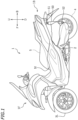
- FIG. 1 is a left side view showing a leaning vehicle 1 according to the present embodiment.
- FIG. 2 is a left side view showing a main part of the leaning vehicle 1.
- FIG. 3 is a left side view showing a part of a front portion 1F of the leaning vehicle 1.
- FIG. 4 is a front view showing a part of the front portion 1F of the leaning vehicle 1.
- FIG. 5 is a plan view showing a part of the front portion 1F of the leaning vehicle 1.
- front, rear, left, right, up and down refer to these directions as viewed from a virtual rider seated on a seat 5 while the leaning vehicle 1 is standing upright (upright as used herein refers to a position where a vehicle body frame 10 to be described below is standing upright) on a horizontal surface with no rider and no load thereon, unless specified otherwise.
- the vehicle up-down direction coincides with the vertical direction.
- the vehicle front-rear direction is orthogonal to the vehicle up-down direction.
- the vehicle left-right direction is orthogonal to the vehicle front-rear direction and the vehicle up-down direction.
- forward refers not only to the direction that extends in the front direction along the vehicle front-rear direction, but also to directions that are inclined from that direction by an angle that is less than 90 degrees.
- rearward refers not only to the direction that extends rearward along the vehicle front-rear direction, but also to directions that are inclined from that direction by an angle that is less than 90 degrees.
- leftward refers not only to the direction that extends leftward along the vehicle left-right direction, but also to directions that are inclined from that direction by an angle that is less than 90 degrees.
- rightward refers not only to the direction that extends rightward along the vehicle left-right direction, but also to directions that are inclined from that direction by an angle that is less than 90 degrees.
- upward refers not only to the direction that extends upward along the vehicle up-down direction, but also to directions that are inclined from that direction by an angle that is less than 90 degrees.
- downward refers not only to the direction that extends downward along the vehicle up-down direction, but also to directions that are inclined from that direction by an angle that is less than 90 degrees.
- the leaning vehicle 1 includes the vehicle body frame 10, a link mechanism 20, a left front wheel 3L, a right front wheel 3R (see FIG. 4 ), a rear wheel 4, a power unit 2, the seat 5, a storage box 40, and an inertial measurement unit (hereinafter referred to as IMU) 6.
- the leaning vehicle 1 is a three-wheeled vehicle including two front wheels 3L, 3R and one rear wheel 4.
- the vehicle body frame 10 includes a head pipe 11, a down frame 12 extending rearward and downward from the head pipe 11, and a seat frame 13 extending rearward from the down frame 12.
- a steering shaft 14 is rotatably supported on the head pipe 11.
- a handle bar 15 is fixed to the steering shaft 14.
- the link mechanism 20 is a link mechanism of the parallel four-section link (parallelogram link) system.
- the link mechanism 20 is arranged upward relative to the left front wheel 3L and the right front wheel 3R.
- the link mechanism 20 includes an upper arm 21, a lower arm 22, a left side member 23 and a right side member 24.
- the upper arm 21 and the lower arm 22 extend leftward and rightward.
- the lower arm 22 is arranged downward of the upper arm 21.
- the upper arm 21 and the lower arm 22 are arranged forward of the head pipe 11 (see FIG. 2 ).
- the upper arm 21 is supported on the head pipe 11 so that the upper arm 21 can rotate about the first axis 21 Cc extending in the vehicle front-rear direction.
- the lower arm 22 is supported on the head pipe 11 so that the lower arm 22 can rotate about the second axis 22Cc extending in the vehicle front-rear direction.
- another lower arm 22B is arranged rearward of the head pipe 11 as shown in FIG. 2 .
- the lower arm 22B extends leftward and rightward.
- the lower arm 22B is arranged downward of the upper arm 21.
- the lower arm 22B is supported on the head pipe 11 so that the lower arm 22B can rotate about the second axis 22Cc extending in the vehicle front-rear direction.
- another upper arm that is supported on the head pipe 11 so that the upper arm can rotate about the first axis 21 Cc may be arranged rearward of the head pipe 11.
- the other upper arm and the other lower arm 22B arranged rearward of the head pipe 11 are not essential.
- the left side member 23 and the right side member 24 extend upward and downward.
- the left side member 23 is arranged leftward of the head pipe 11, and the right side member 24 is arranged rightward of the head pipe 11.
- the right side member 24 is arranged rightward of the left side member 23.
- the left side member 23 and the right side member 24 are arranged rearward of the upper arm 21 and the lower arm 22.
- the left side member 23 and the right side member 24 are arranged forward of the lower arm 22B.
- the left side member 23 and the right side member 24 are rotatably supported on the upper arm 21, the lower arm 22 and the lower arm 22B.
- the upper end portion of the left side member 23 is supported on the left end portion of the upper arm 21 so that the left side member 23 can rotate about the third axis 21Lc extending in the vehicle front-rear direction.
- the lower end portion of the left side member 23 is supported on the left end portion of the lower arm 22 and the left end portion of the lower arm 22B so that the left side member 23 can rotate about the fourth axis 22Lc extending in the vehicle front-rear direction.
- the upper end portion of the right side member 24 is supported on the right end portion of the upper arm 21 so that the right side member 24 can rotate about the fifth axis 21Rc extending in the vehicle front-rear direction.
- the lower end portion of the right side member 24 is supported on the right end portion of the lower arm 22 and the right end portion of the lower arm 22B so that the right side member 24 can rotate about the sixth axis 22Rc extending in the vehicle front-rear direction.
- the leaning vehicle 1 includes a left suspension 25L and a right suspension 25R as front suspensions.
- the left suspension 25L and the right suspension 25R are telescopic suspensions.
- the upper end portion of the left suspension 25L and the upper end portion of the right suspension 25R are connected to the link mechanism 20.
- the lower end portion of the left suspension 25L is connected to the left front wheel 3L, and the lower end portion of the right suspension 25R is connected to the right front wheel 3R.
- the upper end portion of the left suspension 25L is connected to the lower end portion of the left side member 23 via a left bracket 26L.
- the upper end portion of the left suspension 25L is connected to the left side member 23 so that the left suspension 25L can rotate in the left-right direction of the vehicle body frame 10.
- the upper end portion of the right suspension 25R is connected to the lower end portion of the right side member 24 via a right bracket 26R.
- the upper end portion of the right suspension 25R is connected to the right side member 24 so that the right suspension 25R can rotate in the left-right direction of the vehicle body frame 10.
- a center plate 27C is connected to the lower end portion of the steering shaft 14. As shown in FIG. 5 , the center plate 27C extends forward from the steering shaft 14. A left plate 27L is fixed to the left bracket 26L. A right plate 27R is fixed to the right bracket 26R. The left plate 27L, the center plate 27C and the right plate 27R are connected to a tie rod 28 so that they can rotate left and right.
- the steering shaft 14 is linked to the left side member 23 and the right side member 24 via the center plate 27C, the tie rod 28, the left plate 27L and the right plate 27R.
- the leaning vehicle 1 includes the roll angle control device 30 that controls the roll angle.
- the roll angle control device 30 controls the roll angle of the vehicle body frame 10 by adjusting the rotation of the upper arm 21 and the lower arm 22 relative to the vehicle body frame 10.
- the roll angle control device 30 is configured to give a torque to at least one of the upper arm 21 and the lower arm 22.
- the roll angle control device 30 is connected to at least one of the upper arm 21 and the lower arm 22 and to the vehicle body frame 10. In the present embodiment, the roll angle control device 30 is connected to the upper arm 21 and the head pipe 11.
- the roll angle control device 30 includes an actuator 31 that outputs a torque for rotating the upper arm 21 and the lower arm 22 relative to the vehicle body frame 10.
- the actuator 31 is connected to the head pipe 11 via a support member 32.
- the actuator 31 includes a motor 33, which is a power source, and an output shaft 34 that outputs the torque of the motor 33 to the upper arm 21.
- the output shaft 34 is a rotation shaft that rotates by being driven by the motor 33, and is connected to the upper arm 21.
- the motor 33 and the output shaft 34 are connected together by a decelerator including a gear 35A and a gear 35B.
- An output shaft 33a of the motor 33 meshes with the gear 35A.
- the gear 35B meshes with the gear 35A.
- the output shaft 34 is fixed to the gear 35B.
- the torque of the motor 33 is transmitted to the upper arm 21 via the gear 35A, the gear 35B and the output shaft 34. As the motor 33 is driven, a torque about the first axis 21Cc
- the roll angle control device 30 includes a control device 36 that controls the actuator 31.
- the control device 36 is communicably connected to the IMU 6.
- the control device 36 is connected to the IMU 6 via a harness (not shown).
- the control device 36 is configured to receive signals from the IMU 6 and control the actuator 31.
- the control device 36 may be a control circuit mounted on a substrate, or a computer including a processor and a memory.
- the control device 36 may be built in the actuator 31.
- the control device 36 may be provided outside the actuator 31.
- the control device 36 may be an electronic control unit, for example.
- the power unit 2 is pivotally supported on the vehicle body frame 10.
- the power unit 2 is connected to the rear wheel 4 so that power can be transmitted therebetween.
- the power unit 2 generates driving power for travelling.
- the power unit 2 gives power to the rear wheel 4.
- the power unit 2 may include an internal combustion engine or may include an electric motor. In the present embodiment, the power unit 2 includes an internal combustion engine.
- the seat 5 is arranged rearward of the head pipe 11.
- the seat 5 is arranged rearward of the link mechanism 20.
- the seat 5 is supported on the seat frame 13 of the vehicle body frame 10.
- the storage box 40 is arranged downward of the seat 5.
- the storage box 40 is arranged rearward of the link mechanism 20.
- the storage box 40 is supported on the seat frame 13 of the vehicle body frame 10.
- the leaning vehicle 1 includes left and right rear suspensions 50.
- the left rear suspension 50 is arranged leftward of the rear wheel 4, and the right rear suspension 50 is arranged rightward of the rear wheel 4.
- Each rear suspension 50 includes an upper support portion 51 that is supported on the vehicle body frame 10 so that it can pivot about a first pivot center 51c, and a lower support portion 52 that is supported on the rear wheel 4 so that it can pivot about a second pivot center 52c.
- the upper support portion 51 is pivotally supported on the seat frame 13 via a bracket 13B.
- the lower support portion 52 is pivotally supported on a bracket 4B attached to the axle of the rear wheel 4.
- the rear suspensions 50 extend substantially in the vertical direction as the vehicle is viewed from the side.
- the rear suspensions 50 are arranged so that the line segment M50 that connects between the first pivot center 51c and the second pivot center 52c coincides with the vertical line or is inclined by an angle of 10 degrees or less forward or rearward relative to the vertical line as the vehicle is viewed from the side.
- the vehicle body frame 10 includes a support frame 16 arranged rearward of the storage box 40.
- the support frame 16 extends upward.
- the vehicle body frame 10 includes a cross member 17 that connects between the rear end portion of the left seat frame 13 and the rear end portion of the right seat frame 13.
- the cross member 17 extends in the vehicle left-right direction.
- the support frame 16 is fixed to the cross member 17.
- the IMU 6 is supported on the support frame 16. IMUs well known in the art can suitably be used as the IMU 6.
- the IMU 6 detects the angle or angular velocity and the acceleration for three axes.
- the IMU 6 is arranged close to the link mechanism 20 for the vehicle left-right direction and the vehicle up-down direction.
- the IMU 6 is arranged far away from the link mechanism 20 for the vehicle front-rear direction.
- the IMU 6 is arranged relatively rearward. As shown in FIG. 2 , the link mechanism 20 is arranged in the front portion 1F of the leaning vehicle 1, but the IMU 6 is arranged in a rear portion 1B of the leaning vehicle 1.
- FIG. 8 shows the positional relationship between the link mechanism 20 and the IMU 6 as the vehicle is viewed from the front while the leaning vehicle 1 is standing upright (see FIG. 4 ).
- the IMU 6 is arranged downward relative to the upper end 21t of the upper arm 21, upward relative to the lower end 22d of the lower arm 22, rightward relative to the left end 23I of the left side member 23, and leftward relative to the right end 24r of the right side member 24.
- the IMU 6 is arranged inside a rectangle A1 that is delimited by the horizontal line passing through the upper end 21t of the upper arm 21, the horizontal line passing through the lower end 22d of the lower arm 22, the vertical line passing through the left end 23I of the left side member 23, and the vertical line passing through the right end 24r of the right side member 24.
- the IMU 6 may be arranged inside a rectangle A2 that is delimited by the center of rotation (i.e., the third axis 21Lc) for the left side member 23 of the upper arm 21, the center of rotation (i.e., the fifth axis 21Rc) for the right side member 24 of the upper arm 21, the center of rotation (i.e., the sixth axis 22Rc) for the right side member 24 of the lower arm 22, and the center of rotation (i.e., the fourth axis 22Lc) for the left side member 23 of the lower arm 22.
- the IMU 6 may be arranged inside the rectangle A2 even when the vehicle body frame 10 is tilted.
- the IMU 6 is arranged rearward relative to the front end 5f of the seat 5 (see FIG. 1 ). As shown in FIG. 2 , in the present embodiment, the IMU 6 is arranged rearward relative to the power unit 2. The IMU 6 is arranged rearward of the storage box 40. The IMU 6 is arranged rearward relative to the center 4c of the rear wheel 4. The IMU 6 is arranged rearward relative to the first pivot center 51c of the rear suspension 50 as the vehicle is viewed from the side. The IMU 6 is arranged rearward relative to the second pivot center 52c of the rear suspension 50 as the vehicle is viewed from the side.
- the IMU 6 is arranged at a position that is off the straight line L50 passing through the first pivot center 51c and the second pivot center 52c as the vehicle is viewed from the side. That is, the IMU 6 is arranged at a position that does not intersect with the straight line L50 as the vehicle is viewed from the side. Here, the IMU 6 is arranged rearward relative to the straight line L50 as the vehicle is viewed from the side.
- the IMU 6 may be attached to the support frame 16 via a bracket 60.
- the IMU 6 is fixed to the bracket 60, and the bracket 60 is fixed to the support frame 16.
- the bracket 60 includes a plate-shaped main portion 61 extending downward, and left and right arm portions 62 extending forward from the main portion 61. While a hole 61h is formed in the central portion of the main portion 61, the hole 61h is not essential.
- First bolt holes 61a are formed in the upper left portion, the lower left portion, the upper right portion and the lower right portion of the main portion 61.
- the left arm portion 62 extends forward from the left edge portion of the main portion 61.
- the right arm portion 62 extends forward from the right edge portion of the main portion 61.
- the front end portion 62b of the left arm portion 62 is bent leftward.
- the front end portion 62b of the right arm portion 62 is bent rightward.
- the second bolt hole 62a is formed in the front end portion 62b of the arm portion 62.
- the IMU 6 is fixed to the bracket 60 by first bolts 65A.
- the first bolts 65A are inserted through the first bolt holes 61a of the main portion 61 of the bracket 60.
- the first bolts 65A fix the IMU 6 to the bracket 60.
- the support frame 16 includes stays 16A in which bolt holes are formed.
- the bracket 60 is fixed to the stays 16A by second bolts 65B.
- the second bolts 65B are inserted through the second bolt holes 62a of arm portions 62 of the bracket 60 and the bolt holes of the stays 16A.
- the second bolts 65B fix the bracket 60 to the support frame 16.
- the first bolts 65A and the second bolts 65B are so-called rubber mount bolts.
- a rubber is present between the IMU 6 and the bracket 60.
- a rubber is present between the bracket 60 and the support frame 16. Thus, vibrations of the support frame 16 are unlikely to be transmitted to the IMU 6.
- the IMU 6 is arranged between the support frame 16 and the main portion 61 of the bracket 60. That is, the IMU 6 is arranged rearward of the support frame 16 and forward of the main portion 61. A gap is provided between the support frame 16 and the IMU 6.
- the IMU 6 is arranged in an upright position.
- the IMU 6 is arranged so that the dimension H6 of the IMU 6 in the vehicle up-down direction is greater than the dimension L6 in the vehicle front-rear direction.
- the IMU 6 is arranged so that the dimension H6 of the IMU 6 in the vehicle up-down direction is greater than the dimension W6 in the vehicle left-right direction.
- the leaning vehicle 1 since the leaning vehicle 1 according to the present embodiment includes the roll angle control device 30, it is possible to control the roll angle while travelling and while the leaning vehicle 1 is standing still. There is no particular limitation on the control performed by the roll angle control device 30.
- the roll angle control device 30 can execute a self-supporting control as described below, for example.
- a self-supporting control is a control for maintaining the vehicle body frame 10 in an upright position while the leaning vehicle 1 is standing still, for example, at a traffic light. For example, when the rider shifts weight leftward while the leaning vehicle 1 is standing still, a force that causes the vehicle body frame 10 to tilt leftward is applied to the vehicle body frame 10. Therefore, the vehicle body frame 10 tilts leftward.
- the control device 36 detects the tilt of the vehicle body frame 10 based on a signal from the IMU 6. Upon detecting the tilt of the vehicle body frame 10, the control device 36 controls the actuator 31 so as to cancel out the tilt. Specifically, the control device 36 controls the motor 33 so that the roll angle of the vehicle body frame 10 becomes zero.
- the rider seated on the seat 5 uses both feet to maintain the leaning vehicle 1 in an upright position. While standing still, with the roll angle control device 30 executing such a self-supporting control, the rider seated on the seat 5 can maintain the leaning vehicle 1 in an upright position with little force.
- the control device 36 receives a signal from the IMU 6 to control the actuator 31, thereby rotating the upper arm 21 and the lower arm 22 of the link mechanism 20 relative to the vehicle body frame 10.
- the leaning vehicle 1 according to the present embodiment it is possible to control the roll angle of the vehicle body frame 10.
- the sensor for detecting the roll angle of the vehicle body frame 10 Possible choices as the sensor for detecting the roll angle of the vehicle body frame 10 include a rotation sensor that detects the relative rotation of the upper arm 21 and the lower arm 22 with respect to the vehicle body frame 10 or a rotation sensor that detects the rotation of a rotor of the motor 33.
- a rotation sensor needs to be connected directly to the upper arm 21 or the lower arm 22 or connected directly to the motor 33. Since the rotation sensor needs to be arranged in the vicinity of the link mechanism 20, the rotation sensor needs to be arranged in the front portion 1F of the leaning vehicle 1. On the other hand, it is not essential that the IMU 6 be arranged in the vicinity of the link mechanism 20.
- the IMU 6 may be arranged in the front portion 1F of the vehicle. However, when the IMU 6 is arranged in the front portion 1F of the vehicle, the IMU 6 may be affected by heat or vibrations from the motor 33. Even when the IMU 6 is arranged in a portion other than the front portion 1F of the vehicle, the IMU 6 may be susceptible to vibrations and noise from the power unit 2 or vibrations from the road surface, depending on the position in the vehicle left-right direction or the position in the vehicle up-down direction the IMU 6. As a result, the detection precision of the IMU 6 may lower.
- the IMU 6 is arranged downward relative to the upper end 21t of the upper arm 21, upward relative to the lower end 22d of the lower arm 22, rightward relative to the left end 23I of the left side member 23, leftward relative to the right end 24r of the right side member 24, and rearward relative to the front end 5f of the seat 5. While the IMU 6 is arranged close to the link mechanism 20 for the vehicle left-right direction and the vehicle up-down direction, the IMU 6 is arranged far away from the link mechanism 20 for the vehicle front-rear direction. The IMU 6 is not arranged in the front portion 1F of the leaning vehicle 1. Therefore, with the leaning vehicle 1 according to the present embodiment, it is possible to desirably detect the tilt of the vehicle body frame 10 by the IMU 6 while preventing the front portion 1F of the vehicle from becoming larger and more complicated.
- the IMU 6 is arranged rearward relative to the power unit 2.
- the IMU 6 is arranged rearward relative to the center 4c of the rear wheel 4.
- the IMU 6 is arranged rearward of the storage box 40.
- the IMU 6 is unlikely to be affected by heat and vibrations from the power unit 2.
- it is possible to desirably detect the tilt of the vehicle body frame 10 while preventing the front portion 1F of the vehicle from becoming larger and more complicated.
- the IMU 6 is arranged rearward relative to the first pivot center 51c of the rear suspension 50 as the vehicle is viewed from the side.
- the IMU 6 is arranged rearward relative to the second pivot center 52c of the rear suspension 50 as the vehicle is viewed from the side.
- the IMU 6 is arranged at a position that is off a straight line 50L passing through the first pivot center 51c and the second pivot center 52c as the vehicle is viewed from the side. According to the present embodiment, it is possible to reduce the influence of stretching/contraction of the rear suspension 50 on the IMU 6. It is possible to desirably detect the tilt of the vehicle body frame 10 while preventing the front portion 1F of the vehicle from becoming larger and more complicated.
- the IMU 6 is fixed to the support frame 16 via the bracket 60.
- the bracket 60 By attaching the IMU 6 to the bracket 60 and then fixing the bracket 60 to the support frame 16, it is possible to easily assemble the IMU 6 to the vehicle body frame 10.
- the bracket 60 includes the plate-shaped main portion 61 extending downward, and the arm portion 62 extending forward from the main portion 61.
- the IMU 6 is fixed to the main portion 61 by the first bolts 65A inserted through the first bolt holes 61a formed in the main portion 61.
- the bracket 60 is fixed to the support frame 16 by the second bolts 65B inserted through the second bolt holes 62a formed in the arm portion 62.
- the IMU 6 is arranged between the support frame 16 and the main portion 61. According to the present embodiment, the IMU 6 can be desirably assembled to the vehicle body frame 10.
- the IMU 6 is arranged so that the dimension H6 of the IMU 6 in the vehicle up-down direction is greater than the dimension L6 thereof in the vehicle front-rear direction. Since the dimension L6 of the IMU 6 in the vehicle front-rear direction is relatively small, the IMU 6 can be arranged in a compact arrangement in the rear portion 1B of the vehicle. It is possible to prevent the rear portion 1B of the vehicle from becoming large in the vehicle front-rear direction.
- the roll angle control device 30 executes a self-supporting control.
- the control device 36 is configured to control the actuator 31 so that the vehicle body frame 10 is in an upright position while the leaning vehicle 1 is standing still.
- the rider can stably maintain the attitude while the leaning vehicle 1 is standing still, for example, at a traffic light.
- the upper arm 21 and the lower arm 22 of the link mechanism 20 are not limited to a curved shape as the vehicle is viewed from the front, but may be in a straight shape as the vehicle is viewed from the front.
- the upper arm 21 and the lower arm 22 are not limited to plate-shaped arms.
- the actuator 31 is connected to the upper arm 21 and configured to transmit the torque of the motor 33 to the upper arm 21.
- the actuator 31 may be connected to the lower arm 22 and configured to transmit the torque of the motor 33 to the lower arm 22.
- the actuator 31 may be connected to both of the upper arm 21 and the lower arm 22 and configured to transmit the torque of the motor 33 to both of the upper arm 21 and the lower arm 22.
- IMU 6 is arranged rearward relative to the center 4c of the rear wheel 4.
- the IMU 6 may be arranged forward relative to the first pivot center 51c as the vehicle is viewed from the side.
- the IMU 6 is arranged forward relative to the second pivot center 52c as the vehicle is viewed from the side.
- the IMU 6 may be arranged on the straight line L50 passing through the first pivot center 51c and the second pivot center 52c as the vehicle is viewed from the side.
- the IMU 6 may be arranged forward relative to the rear end of the storage box 40.
- the IMU 6 may be arranged rearward of the main portion 61 of the bracket 60. There is no limitation on the shape of the bracket 60 to which the IMU 6 is attached.
- the stay 16A present between the bracket 60 and the support frame 16 is not essential.
- the bracket 60 may be directly attached to the support frame 16.
- the bracket 60 may be omitted by directly attaching the IMU 6 to the support frame 16.
- the IMU 6 may be supported on a part of the vehicle body frame 10 other than the support frame 16.
- the support frame 16 is not essential.
- the IMU 6 may be arranged so that the dimension H6 in the vehicle up-down direction is less than or equal to the dimension L6 in the vehicle front-rear direction.
- the IMU 6 may be arranged so that the dimension H6 in the vehicle up-down direction is less than or equal to the dimension W6 in the vehicle left-right direction.
- the arrangement of the rear suspension 50 of the embodiment described above is merely an example.
- the rear suspension 50 may be arranged so that line segment M50 that connects between the first pivot center 51c and the second pivot center 52c is inclined by an angle of 10 degrees or more relative to the vertical line as the vehicle is viewed from the side.
Landscapes
- Engineering & Computer Science (AREA)
- Mechanical Engineering (AREA)
- Automatic Cycles, And Cycles In General (AREA)
Description
- The present invention relates to a leaning vehicle according to the preamble of
independent claim 1. In particular such leaning vehicle includes a left front wheel and a right front wheel and is capable of leaning leftward and rightward when turning. Such a leaning vehicle can be taken from the prior art documentEP 3 421 341 A1 . - Furthermore, the prior art document
EP 3 072 794 A1 or the prior art documentWO 2020/138395 A1 discloses a leaning vehicle having a vehicle body frame. A link mechanism is supported on the vehicle body frame. A left front wheel is supported on the link mechanism. A right front wheel is supported on the link mechanism and arranged rightward of the left front wheel in a vehicle left-right direction. A rear wheel is supported on the vehicle body frame and arranged rearward relative to the left front wheel and the right front wheel in a vehicle front-rear direction. A seat is supported on the vehicle body frame and arranged rearward relative to the link mechanism in the vehicle front-rear direction. The link mechanism includes an upper arm supported on the vehicle body frame so that the upper arm is rotatable about a first axis extending in the vehicle front-rear direction, and extending leftward and rightward in the vehicle left-right direction, a lower arm supported on the vehicle body frame so that the lower arm is rotatable about a second axis extending in the vehicle front-rear direction, extending leftward and rightward in the vehicle left-right direction, and arranged downward of the upper arm in a vehicle up-down direction. A left side member is connected to the upper arm so that the left side member is rotatable about a third axis extending in the vehicle front-rear direction, connected to the lower arm so that the left side member is rotatable about a fourth axis extending in the vehicle front-rear direction, and extending upward and downward in the vehicle up-down direction. A right side member is supported on the upper arm so that the right side member is rotatable about a fifth axis extending in the vehicle front-rear direction, supported on the lower arm so that the right side member is rotatable about a sixth axis extending in the vehicle front-rear direction, extending upward and downward in the vehicle up-down direction, and arranged rightward of the left side member in the vehicle left-right direction. The leaning vehicle comprises an actuator connected to the vehicle body frame and at least one of the upper arm and the lower arm, and configured to generate a torque that rotates the upper arm and the lower arm relative to the vehicle body frame. An inertial measurement unit is supported on the vehicle body frame. A control device is configured to receive a signal from the inertial measurement unit to control the actuator. - As disclosed in International Publication
WO 2020/050157 A , for example, leaning vehicles have been known in the art, which include a left front wheel, a right front wheel and a vehicle body frame, and include a link mechanism of the parallel four-section link (also called parallelogram link) system as a mechanism for leaning the vehicle body frame. The vehicle body frame includes a head pipe that supports the steering shaft so that the steering shaft can rotate left and right. The link mechanism includes an upper arm and a lower arm extending leftward and rightward, a left side member arranged leftward of the head pipe, and a right side member arranged rightward of the head pipe. The upper arm and the lower arm are rotatably supported on the head pipe. The left side member and the right side member are rotatably connected to the upper arm and the lower arm. When the vehicle body frame leans leftward or rightward, the upper arm and the lower arm rotate relative to the head pipe. -
JP 2018-149962 A JP 2018-149962 A - Now, the rotation sensor that detects the relative rotation of the upper arm and the lower arm with respect to the vehicle body frame needs to be arranged in the vicinity of the upper arm and the lower arm. The rotation sensor that detects the rotation of the rotor of the motor needs to be arranged in the vicinity of the motor. Therefore, with the leaning vehicle disclosed in
JP 2018-149962 A - An object of the present invention is to provide a leaning vehicle with which it is possible to desirably control the lean angle of the vehicle body frame while preventing the front portion of the vehicle from becoming larger and more complicated. According to the present invention said object is solved by a leaning vehicle having the features of
independent claim 1. Preferred embodiments are laid down in the dependent claims. - A leaning vehicle disclosed herein includes: a vehicle body frame; a link mechanism supported on the vehicle body frame; a left front wheel supported on the link mechanism; a right front wheel supported on the link mechanism and arranged rightward of the left front wheel; a rear wheel supported on the vehicle body frame and arranged rearward relative to the left front wheel and the right front wheel; and a seat supported on the vehicle body frame and arranged rearward relative to the link mechanism. The link mechanism includes: an upper arm supported on the vehicle body frame so that the upper arm is rotatable about a first axis extending in a vehicle front-rear direction, and extending leftward and rightward; a lower arm supported on the vehicle body frame so that the lower arm is rotatable about a second axis extending in the vehicle front-rear direction, extending leftward and rightward, and arranged downward of the upper arm; a left side member connected to the upper arm so that the left side member is rotatable about a third axis extending in the vehicle front-rear direction, connected to the lower arm so that the left side member is rotatable about a fourth axis extending in the vehicle front-rear direction, and extending upward and downward; and a right side member supported on the upper arm so that the right side member is rotatable about a fifth axis extending in the vehicle front-rear direction, supported on the lower arm so that the right side member is rotatable about a sixth axis extending in the vehicle front-rear direction, extending upward and downward, and arranged rightward of the left side member. The leaning vehicle includes an actuator, an inertial measurement unit, and a control device that receives a signal from the inertial measurement unit to control the actuator. The actuator is connected to the vehicle body frame and at least one of the upper arm and the lower arm, and configured to generate a torque that rotates the upper arm and the lower arm relative to the vehicle body frame. The inertial measurement unit is supported on the vehicle body frame, and arranged downward relative to an upper end of the upper arm, upward relative to a lower end of the lower arm, rightward relative to a left end of the left side member, leftward relative to a right end of the right side member, and rearward relative to a center of the rear wheel in the vehicle front-rear direction.
- With the leaning vehicle described above, the control device receives a signal from the inertial measurement unit to control the actuator, thereby rotating the upper arm and the lower arm of the link mechanism relative to the vehicle body frame. Thus, the leftward or rightward lean angle of the vehicle body frame is controlled. As opposed to a rotation sensor that detects the relative rotation between the upper arm and the lower arm and the vehicle body frame and a rotation sensor that detects the rotation of the rotor of the motor, it is not essential that the inertial measurement unit be arranged in the vicinity of the link mechanism.
- Needless to say, the inertial measurement unit can be arranged in the front portion of the vehicle. In order to detect the behavior of the left front wheel and the right front wheel by the inertial measurement unit and control the actuator based on the behavior, it is suitable that the inertial measurement unit be arranged in the vicinity of the link mechanism. On the other hand, studies are made on how to control the attitude of the vehicle body frame by other methods, instead of controlling the attitude of the vehicle body frame based on the result of detecting the behavior of the left front wheel and the right front wheel and the behavior of the vehicle body in the vicinity of the link mechanism. As a result, the arrangement of the inertial measurement unit that is suitable for controlling the attitude of the vehicle body frame, other than the vicinity of the link mechanism can be suggested.
- With the leaning vehicle described above, the inertial measurement unit is arranged close to the link mechanism for the vehicle up-down direction and the vehicle left-right direction, but is arranged rearward relative to the front end of the seat and rearward relative to a center of the rear wheel in the vehicle front-rear direction. The inertial measurement unit is arranged far away from the link mechanism for the vehicle front-rear direction. Therefore, it is possible to desirably detect the lean of the vehicle body frame by the inertial measurement unit while preventing the front portion of the vehicle from becoming larger and more complicated.
- The leaning vehicle may include a power unit pivotally supported on the vehicle body frame and connected to the rear wheel so that power can be transmitted therebetween. The inertial measurement unit may be arranged rearward relative to the power unit.
- Thus, the inertial measurement unit is unlikely to be affected by heat and vibrations generated from the power unit. Therefore, it is possible to desirably detect the tilt of the vehicle body frame while preventing the front portion of the vehicle from becoming larger and more complicated.
- According to the invention the inertial measurement unit is arranged rearward relative to a center of the rear wheel.
- The leaning vehicle may include a rear suspension including an upper support portion supported on the vehicle body frame so that the upper support portion is pivotable about a first pivot center, and a lower support portion supported on the rear wheel so that the lower support portion is pivotable about a second pivot center.
- The inertial measurement unit may be arranged rearward relative to the first pivot center as the vehicle is viewed from the side.
- The inertial measurement unit may be arranged rearward relative to the second pivot center as the vehicle is viewed from the side.
- The inertial measurement unit may be arranged at a position that is off a straight line passing through the first pivot center and the second pivot center as the vehicle is viewed from the side.
- The rear suspension may be arranged so that a line segment that connects together the first pivot center and the second pivot center coincides with a vertical line or is inclined by an angle of 10 degrees or less relative to the vertical line as the vehicle is viewed from the side.
- The leaning vehicle may include a storage box supported on the vehicle body frame and arranged downward of the seat. The inertial measurement unit may be arranged rearward of the storage box.
- The vehicle body frame may include a support frame arranged rearward of the storage box. The leaning vehicle may include a bracket fixed to the support frame and attached to the inertial measurement unit.
- The bracket may include a plate-shaped main portion having a first bolt hole formed therein and extending downward, and an arm portion having a second bolt hole formed therein and extending forward from the main portion. The leaning vehicle may include a first bolt inserted through the first bolt hole and fixing the inertial measurement unit to the bracket, and a second bolt inserted through the second bolt hole and fixing the bracket to the support frame. The inertial measurement unit may be arranged between the support frame and the main portion of the bracket.
- The inertial measurement unit may be arranged so that a dimension of the inertial measurement unit in a vehicle up-down direction is greater than a dimension of the inertial measurement unit in the vehicle front-rear direction.
- The control device may be configured to control the actuator so that the vehicle body frame is in an upright position while the leaning vehicle is standing still.
- According to the present invention, it is possible to provide a leaning vehicle with which it is possible to desirably control the lean angle of the vehicle body frame while preventing the front portion of the vehicle from becoming larger and more complicated.
-
-
FIG. 1 is a left side view showing a leaning vehicle according to one embodiment. -
FIG. 2 is a left side view showing a main part of the leaning vehicle. -
FIG. 3 is a left side view showing a part of a front portion of the leaning vehicle. -
FIG. 4 is a front view showing a part of the front portion of the leaning vehicle. -
FIG. 5 is a plan view showing a part of the front portion of the leaning vehicle. -
FIG. 6 is a perspective view showing a part of the rear portion of the leaning vehicle. -
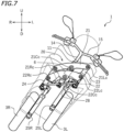
FIG. 7 is a front view showing a part of the front portion of the leaning vehicle when the vehicle body frame is leaning leftward. -
FIG. 8 is a front view showing a part of the leaning vehicle. -
FIG. 9 is a perspective view showing a part of the rear portion of the leaning vehicle. - A leaning vehicle according to one embodiment will now be described with reference to the drawings.
FIG. 1 is a left side view showing a leaningvehicle 1 according to the present embodiment.FIG. 2 is a left side view showing a main part of the leaningvehicle 1.FIG. 3 is a left side view showing a part of afront portion 1F of the leaningvehicle 1.FIG. 4 is a front view showing a part of thefront portion 1F of the leaningvehicle 1.FIG. 5 is a plan view showing a part of thefront portion 1F of the leaningvehicle 1. - The terms front, rear, left, right, up and down, as used in the description below, refer to these directions as viewed from a virtual rider seated on a
seat 5 while the leaningvehicle 1 is standing upright (upright as used herein refers to a position where avehicle body frame 10 to be described below is standing upright) on a horizontal surface with no rider and no load thereon, unless specified otherwise. The designations F, B, L, R, U and D, as used in the figures, refer to front, rear, left, right, up and down, respectively. The vehicle up-down direction coincides with the vertical direction. The vehicle front-rear direction is orthogonal to the vehicle up-down direction. The vehicle left-right direction is orthogonal to the vehicle front-rear direction and the vehicle up-down direction. - The term "forward" refers not only to the direction that extends in the front direction along the vehicle front-rear direction, but also to directions that are inclined from that direction by an angle that is less than 90 degrees. The term "rearward" refers not only to the direction that extends rearward along the vehicle front-rear direction, but also to directions that are inclined from that direction by an angle that is less than 90 degrees. The term "leftward" refers not only to the direction that extends leftward along the vehicle left-right direction, but also to directions that are inclined from that direction by an angle that is less than 90 degrees. The term "rightward" refers not only to the direction that extends rightward along the vehicle left-right direction, but also to directions that are inclined from that direction by an angle that is less than 90 degrees. The term "upward" refers not only to the direction that extends upward along the vehicle up-down direction, but also to directions that are inclined from that direction by an angle that is less than 90 degrees. The term "downward" refers not only to the direction that extends downward along the vehicle up-down direction, but also to directions that are inclined from that direction by an angle that is less than 90 degrees.
- As shown in
FIG. 1 andFIG. 2 , the leaningvehicle 1 includes thevehicle body frame 10, alink mechanism 20, aleft front wheel 3L, aright front wheel 3R (seeFIG. 4 ), arear wheel 4, apower unit 2, theseat 5, astorage box 40, and an inertial measurement unit (hereinafter referred to as IMU) 6. The leaningvehicle 1 is a three-wheeled vehicle including twofront wheels rear wheel 4. - As shown in
FIG. 2 , thevehicle body frame 10 includes ahead pipe 11, adown frame 12 extending rearward and downward from thehead pipe 11, and aseat frame 13 extending rearward from thedown frame 12. As shown inFIG. 4 , a steeringshaft 14 is rotatably supported on thehead pipe 11. Ahandle bar 15 is fixed to the steeringshaft 14. - The
link mechanism 20 is a link mechanism of the parallel four-section link (parallelogram link) system. Thelink mechanism 20 is arranged upward relative to theleft front wheel 3L and theright front wheel 3R. Thelink mechanism 20 includes anupper arm 21, alower arm 22, aleft side member 23 and aright side member 24. - The
upper arm 21 and thelower arm 22 extend leftward and rightward. Thelower arm 22 is arranged downward of theupper arm 21. Theupper arm 21 and thelower arm 22 are arranged forward of the head pipe 11 (seeFIG. 2 ). Theupper arm 21 is supported on thehead pipe 11 so that theupper arm 21 can rotate about thefirst axis 21 Cc extending in the vehicle front-rear direction. Thelower arm 22 is supported on thehead pipe 11 so that thelower arm 22 can rotate about the second axis 22Cc extending in the vehicle front-rear direction. - In the present embodiment, another
lower arm 22B is arranged rearward of thehead pipe 11 as shown inFIG. 2 . Thelower arm 22B extends leftward and rightward. Thelower arm 22B is arranged downward of theupper arm 21. As is thelower arm 22, thelower arm 22B is supported on thehead pipe 11 so that thelower arm 22B can rotate about the second axis 22Cc extending in the vehicle front-rear direction. Note that another upper arm that is supported on thehead pipe 11 so that the upper arm can rotate about thefirst axis 21 Cc may be arranged rearward of thehead pipe 11. Note however that the other upper arm and the otherlower arm 22B arranged rearward of thehead pipe 11 are not essential. - As shown in
FIG. 4 , theleft side member 23 and theright side member 24 extend upward and downward. Theleft side member 23 is arranged leftward of thehead pipe 11, and theright side member 24 is arranged rightward of thehead pipe 11. Theright side member 24 is arranged rightward of theleft side member 23. Theleft side member 23 and theright side member 24 are arranged rearward of theupper arm 21 and thelower arm 22. Theleft side member 23 and theright side member 24 are arranged forward of thelower arm 22B. Theleft side member 23 and theright side member 24 are rotatably supported on theupper arm 21, thelower arm 22 and thelower arm 22B. - Specifically, the upper end portion of the
left side member 23 is supported on the left end portion of theupper arm 21 so that theleft side member 23 can rotate about the third axis 21Lc extending in the vehicle front-rear direction. The lower end portion of theleft side member 23 is supported on the left end portion of thelower arm 22 and the left end portion of thelower arm 22B so that theleft side member 23 can rotate about the fourth axis 22Lc extending in the vehicle front-rear direction. The upper end portion of theright side member 24 is supported on the right end portion of theupper arm 21 so that theright side member 24 can rotate about the fifth axis 21Rc extending in the vehicle front-rear direction. The lower end portion of theright side member 24 is supported on the right end portion of thelower arm 22 and the right end portion of thelower arm 22B so that theright side member 24 can rotate about the sixth axis 22Rc extending in the vehicle front-rear direction. - The leaning
vehicle 1 includes aleft suspension 25L and aright suspension 25R as front suspensions. In the present embodiment, theleft suspension 25L and theright suspension 25R are telescopic suspensions. The upper end portion of theleft suspension 25L and the upper end portion of theright suspension 25R are connected to thelink mechanism 20. The lower end portion of theleft suspension 25L is connected to theleft front wheel 3L, and the lower end portion of theright suspension 25R is connected to theright front wheel 3R. Specifically, the upper end portion of theleft suspension 25L is connected to the lower end portion of theleft side member 23 via aleft bracket 26L. The upper end portion of theleft suspension 25L is connected to theleft side member 23 so that theleft suspension 25L can rotate in the left-right direction of thevehicle body frame 10. The upper end portion of theright suspension 25R is connected to the lower end portion of theright side member 24 via aright bracket 26R. The upper end portion of theright suspension 25R is connected to theright side member 24 so that theright suspension 25R can rotate in the left-right direction of thevehicle body frame 10. - A
center plate 27C is connected to the lower end portion of the steeringshaft 14. As shown inFIG. 5 , thecenter plate 27C extends forward from the steeringshaft 14. Aleft plate 27L is fixed to theleft bracket 26L. Aright plate 27R is fixed to theright bracket 26R. Theleft plate 27L, thecenter plate 27C and theright plate 27R are connected to atie rod 28 so that they can rotate left and right. The steeringshaft 14 is linked to theleft side member 23 and theright side member 24 via thecenter plate 27C, thetie rod 28, theleft plate 27L and theright plate 27R. - As shown in
FIG. 3 , the leaningvehicle 1 includes the rollangle control device 30 that controls the roll angle. Note that the rollangle control device 30 is not shown in figures other thanFIG. 3 . The rollangle control device 30 controls the roll angle of thevehicle body frame 10 by adjusting the rotation of theupper arm 21 and thelower arm 22 relative to thevehicle body frame 10. The rollangle control device 30 is configured to give a torque to at least one of theupper arm 21 and thelower arm 22. The rollangle control device 30 is connected to at least one of theupper arm 21 and thelower arm 22 and to thevehicle body frame 10. In the present embodiment, the rollangle control device 30 is connected to theupper arm 21 and thehead pipe 11. - The roll
angle control device 30 includes anactuator 31 that outputs a torque for rotating theupper arm 21 and thelower arm 22 relative to thevehicle body frame 10. Theactuator 31 is connected to thehead pipe 11 via asupport member 32. Theactuator 31 includes amotor 33, which is a power source, and anoutput shaft 34 that outputs the torque of themotor 33 to theupper arm 21. Theoutput shaft 34 is a rotation shaft that rotates by being driven by themotor 33, and is connected to theupper arm 21. Themotor 33 and theoutput shaft 34 are connected together by a decelerator including agear 35A and agear 35B. Anoutput shaft 33a of themotor 33 meshes with thegear 35A. Thegear 35B meshes with thegear 35A. Theoutput shaft 34 is fixed to thegear 35B. The torque of themotor 33 is transmitted to theupper arm 21 via thegear 35A, thegear 35B and theoutput shaft 34. As themotor 33 is driven, a torque about the first axis 21Cc (seeFIG. 4 ) is given to theupper arm 21. - The roll
angle control device 30 includes acontrol device 36 that controls theactuator 31. Thecontrol device 36 is communicably connected to theIMU 6. In the present embodiment, thecontrol device 36 is connected to theIMU 6 via a harness (not shown). Thecontrol device 36 is configured to receive signals from theIMU 6 and control theactuator 31. For example, thecontrol device 36 may be a control circuit mounted on a substrate, or a computer including a processor and a memory. Thecontrol device 36 may be built in theactuator 31. Thecontrol device 36 may be provided outside theactuator 31. Thecontrol device 36 may be an electronic control unit, for example. - As shown in
FIG. 2 , thepower unit 2 is pivotally supported on thevehicle body frame 10. Thepower unit 2 is connected to therear wheel 4 so that power can be transmitted therebetween. Thepower unit 2 generates driving power for travelling. Thepower unit 2 gives power to therear wheel 4. Thepower unit 2 may include an internal combustion engine or may include an electric motor. In the present embodiment, thepower unit 2 includes an internal combustion engine. - As shown in
FIG. 1 andFIG. 2 , theseat 5 is arranged rearward of thehead pipe 11. Theseat 5 is arranged rearward of thelink mechanism 20. Theseat 5 is supported on theseat frame 13 of thevehicle body frame 10. - The
storage box 40 is arranged downward of theseat 5. Thestorage box 40 is arranged rearward of thelink mechanism 20. Thestorage box 40 is supported on theseat frame 13 of thevehicle body frame 10. - The leaning
vehicle 1 includes left and rightrear suspensions 50. The leftrear suspension 50 is arranged leftward of therear wheel 4, and the rightrear suspension 50 is arranged rightward of therear wheel 4. Eachrear suspension 50 includes anupper support portion 51 that is supported on thevehicle body frame 10 so that it can pivot about afirst pivot center 51c, and alower support portion 52 that is supported on therear wheel 4 so that it can pivot about asecond pivot center 52c. Here, theupper support portion 51 is pivotally supported on theseat frame 13 via abracket 13B. Thelower support portion 52 is pivotally supported on abracket 4B attached to the axle of therear wheel 4. Therear suspensions 50 extend substantially in the vertical direction as the vehicle is viewed from the side. Specifically, therear suspensions 50 are arranged so that the line segment M50 that connects between thefirst pivot center 51c and thesecond pivot center 52c coincides with the vertical line or is inclined by an angle of 10 degrees or less forward or rearward relative to the vertical line as the vehicle is viewed from the side. - As shown in
FIG. 6 , thevehicle body frame 10 includes asupport frame 16 arranged rearward of thestorage box 40. Thesupport frame 16 extends upward. Thevehicle body frame 10 includes across member 17 that connects between the rear end portion of theleft seat frame 13 and the rear end portion of theright seat frame 13. Thecross member 17 extends in the vehicle left-right direction. Thesupport frame 16 is fixed to thecross member 17. - As shown in
FIG. 2 , theIMU 6 is supported on thesupport frame 16. IMUs well known in the art can suitably be used as theIMU 6. TheIMU 6 detects the angle or angular velocity and the acceleration for three axes. - When the
vehicle body frame 10 leans leftward or rightward as shown inFIG. 7 , the position of thelink mechanism 20 relative to thevehicle body frame 10 changes. In the present embodiment, theIMU 6 is arranged close to thelink mechanism 20 for the vehicle left-right direction and the vehicle up-down direction. On the other hand, theIMU 6 is arranged far away from thelink mechanism 20 for the vehicle front-rear direction. TheIMU 6 is arranged relatively rearward. As shown inFIG. 2 , thelink mechanism 20 is arranged in thefront portion 1F of the leaningvehicle 1, but theIMU 6 is arranged in arear portion 1B of the leaningvehicle 1. -
FIG. 8 shows the positional relationship between thelink mechanism 20 and theIMU 6 as the vehicle is viewed from the front while the leaningvehicle 1 is standing upright (seeFIG. 4 ). As shown inFIG. 8 , while the leaningvehicle 1 standing upright, theIMU 6 is arranged downward relative to theupper end 21t of theupper arm 21, upward relative to thelower end 22d of thelower arm 22, rightward relative to the left end 23I of theleft side member 23, and leftward relative to theright end 24r of theright side member 24. As the vehicle is viewed from the front while the leaningvehicle 1 is standing upright, theIMU 6 is arranged inside a rectangle A1 that is delimited by the horizontal line passing through theupper end 21t of theupper arm 21, the horizontal line passing through thelower end 22d of thelower arm 22, the vertical line passing through the left end 23I of theleft side member 23, and the vertical line passing through theright end 24r of theright side member 24. As the vehicle is viewed from the front while the leaningvehicle 1 is standing upright, theIMU 6 may be arranged inside a rectangle A2 that is delimited by the center of rotation (i.e., the third axis 21Lc) for theleft side member 23 of theupper arm 21, the center of rotation (i.e., the fifth axis 21Rc) for theright side member 24 of theupper arm 21, the center of rotation (i.e., the sixth axis 22Rc) for theright side member 24 of thelower arm 22, and the center of rotation (i.e., the fourth axis 22Lc) for theleft side member 23 of thelower arm 22. As shown inFIG. 7 , theIMU 6 may be arranged inside the rectangle A2 even when thevehicle body frame 10 is tilted. - For the vehicle front-rear direction, the
IMU 6 is arranged rearward relative to thefront end 5f of the seat 5 (seeFIG. 1 ). As shown inFIG. 2 , in the present embodiment, theIMU 6 is arranged rearward relative to thepower unit 2. TheIMU 6 is arranged rearward of thestorage box 40. TheIMU 6 is arranged rearward relative to thecenter 4c of therear wheel 4. TheIMU 6 is arranged rearward relative to thefirst pivot center 51c of therear suspension 50 as the vehicle is viewed from the side. TheIMU 6 is arranged rearward relative to thesecond pivot center 52c of therear suspension 50 as the vehicle is viewed from the side. TheIMU 6 is arranged at a position that is off the straight line L50 passing through thefirst pivot center 51c and thesecond pivot center 52c as the vehicle is viewed from the side. That is, theIMU 6 is arranged at a position that does not intersect with the straight line L50 as the vehicle is viewed from the side. Here, theIMU 6 is arranged rearward relative to the straight line L50 as the vehicle is viewed from the side. - There is no particular limitation on the configuration used to attach the
IMU 6 to thesupport frame 16. For example, as shown inFIG. 9 , theIMU 6 may be attached to thesupport frame 16 via abracket 60. In the present embodiment, theIMU 6 is fixed to thebracket 60, and thebracket 60 is fixed to thesupport frame 16. - The
bracket 60 includes a plate-shapedmain portion 61 extending downward, and left andright arm portions 62 extending forward from themain portion 61. While ahole 61h is formed in the central portion of themain portion 61, thehole 61h is not essential.First bolt holes 61a are formed in the upper left portion, the lower left portion, the upper right portion and the lower right portion of themain portion 61. Theleft arm portion 62 extends forward from the left edge portion of themain portion 61. Theright arm portion 62 extends forward from the right edge portion of themain portion 61. Thefront end portion 62b of theleft arm portion 62 is bent leftward. Thefront end portion 62b of theright arm portion 62 is bent rightward. Thesecond bolt hole 62a is formed in thefront end portion 62b of thearm portion 62. - The
IMU 6 is fixed to thebracket 60 byfirst bolts 65A. Thefirst bolts 65A are inserted through thefirst bolt holes 61a of themain portion 61 of thebracket 60. Thefirst bolts 65A fix theIMU 6 to thebracket 60. Thesupport frame 16 includesstays 16A in which bolt holes are formed. Thebracket 60 is fixed to thestays 16A bysecond bolts 65B. Thesecond bolts 65B are inserted through thesecond bolt holes 62a ofarm portions 62 of thebracket 60 and the bolt holes of thestays 16A. Thesecond bolts 65B fix thebracket 60 to thesupport frame 16. Thefirst bolts 65A and thesecond bolts 65B are so-called rubber mount bolts. A rubber is present between theIMU 6 and thebracket 60. A rubber is present between thebracket 60 and thesupport frame 16. Thus, vibrations of thesupport frame 16 are unlikely to be transmitted to theIMU 6. Note however that there is no particular limitation on the type of thefirst bolts 65A and thesecond bolts 65B. - The
IMU 6 is arranged between thesupport frame 16 and themain portion 61 of thebracket 60. That is, theIMU 6 is arranged rearward of thesupport frame 16 and forward of themain portion 61. A gap is provided between thesupport frame 16 and theIMU 6. - In the present embodiment, the
IMU 6 is arranged in an upright position. TheIMU 6 is arranged so that the dimension H6 of theIMU 6 in the vehicle up-down direction is greater than the dimension L6 in the vehicle front-rear direction. TheIMU 6 is arranged so that the dimension H6 of theIMU 6 in the vehicle up-down direction is greater than the dimension W6 in the vehicle left-right direction. - Since the leaning
vehicle 1 according to the present embodiment includes the rollangle control device 30, it is possible to control the roll angle while travelling and while the leaningvehicle 1 is standing still. There is no particular limitation on the control performed by the rollangle control device 30. The rollangle control device 30 can execute a self-supporting control as described below, for example. - A self-supporting control is a control for maintaining the
vehicle body frame 10 in an upright position while the leaningvehicle 1 is standing still, for example, at a traffic light. For example, when the rider shifts weight leftward while the leaningvehicle 1 is standing still, a force that causes thevehicle body frame 10 to tilt leftward is applied to thevehicle body frame 10. Therefore, thevehicle body frame 10 tilts leftward. Thecontrol device 36 detects the tilt of thevehicle body frame 10 based on a signal from theIMU 6. Upon detecting the tilt of thevehicle body frame 10, thecontrol device 36 controls theactuator 31 so as to cancel out the tilt. Specifically, thecontrol device 36 controls themotor 33 so that the roll angle of thevehicle body frame 10 becomes zero. While standing still, the rider seated on theseat 5 uses both feet to maintain the leaningvehicle 1 in an upright position. While standing still, with the rollangle control device 30 executing such a self-supporting control, the rider seated on theseat 5 can maintain the leaningvehicle 1 in an upright position with little force. - As described above, with the leaning
vehicle 1 according to the present embodiment, thecontrol device 36 receives a signal from theIMU 6 to control theactuator 31, thereby rotating theupper arm 21 and thelower arm 22 of thelink mechanism 20 relative to thevehicle body frame 10. With the leaningvehicle 1 according to the present embodiment, it is possible to control the roll angle of thevehicle body frame 10. - Possible choices as the sensor for detecting the roll angle of the
vehicle body frame 10 include a rotation sensor that detects the relative rotation of theupper arm 21 and thelower arm 22 with respect to thevehicle body frame 10 or a rotation sensor that detects the rotation of a rotor of themotor 33. However, such a rotation sensor needs to be connected directly to theupper arm 21 or thelower arm 22 or connected directly to themotor 33. Since the rotation sensor needs to be arranged in the vicinity of thelink mechanism 20, the rotation sensor needs to be arranged in thefront portion 1F of the leaningvehicle 1. On the other hand, it is not essential that theIMU 6 be arranged in the vicinity of thelink mechanism 20. - The
IMU 6 may be arranged in thefront portion 1F of the vehicle. However, when theIMU 6 is arranged in thefront portion 1F of the vehicle, theIMU 6 may be affected by heat or vibrations from themotor 33. Even when theIMU 6 is arranged in a portion other than thefront portion 1F of the vehicle, theIMU 6 may be susceptible to vibrations and noise from thepower unit 2 or vibrations from the road surface, depending on the position in the vehicle left-right direction or the position in the vehicle up-down direction theIMU 6. As a result, the detection precision of theIMU 6 may lower. - In the present embodiment, however, the
IMU 6 is arranged downward relative to theupper end 21t of theupper arm 21, upward relative to thelower end 22d of thelower arm 22, rightward relative to the left end 23I of theleft side member 23, leftward relative to theright end 24r of theright side member 24, and rearward relative to thefront end 5f of theseat 5. While theIMU 6 is arranged close to thelink mechanism 20 for the vehicle left-right direction and the vehicle up-down direction, theIMU 6 is arranged far away from thelink mechanism 20 for the vehicle front-rear direction. TheIMU 6 is not arranged in thefront portion 1F of the leaningvehicle 1. Therefore, with the leaningvehicle 1 according to the present embodiment, it is possible to desirably detect the tilt of thevehicle body frame 10 by theIMU 6 while preventing thefront portion 1F of the vehicle from becoming larger and more complicated. - According to the present embodiment, the
IMU 6 is arranged rearward relative to thepower unit 2. TheIMU 6 is arranged rearward relative to thecenter 4c of therear wheel 4. TheIMU 6 is arranged rearward of thestorage box 40. TheIMU 6 is unlikely to be affected by heat and vibrations from thepower unit 2. Thus, it is possible to desirably detect the tilt of thevehicle body frame 10 while preventing thefront portion 1F of the vehicle from becoming larger and more complicated. - According to the present embodiment, the
IMU 6 is arranged rearward relative to thefirst pivot center 51c of therear suspension 50 as the vehicle is viewed from the side. TheIMU 6 is arranged rearward relative to thesecond pivot center 52c of therear suspension 50 as the vehicle is viewed from the side. TheIMU 6 is arranged at a position that is off a straight line 50L passing through thefirst pivot center 51c and thesecond pivot center 52c as the vehicle is viewed from the side. According to the present embodiment, it is possible to reduce the influence of stretching/contraction of therear suspension 50 on theIMU 6. It is possible to desirably detect the tilt of thevehicle body frame 10 while preventing thefront portion 1F of the vehicle from becoming larger and more complicated. - According to the present embodiment, the
IMU 6 is fixed to thesupport frame 16 via thebracket 60. By attaching theIMU 6 to thebracket 60 and then fixing thebracket 60 to thesupport frame 16, it is possible to easily assemble theIMU 6 to thevehicle body frame 10. - According to the present embodiment, the
bracket 60 includes the plate-shapedmain portion 61 extending downward, and thearm portion 62 extending forward from themain portion 61. TheIMU 6 is fixed to themain portion 61 by thefirst bolts 65A inserted through thefirst bolt holes 61a formed in themain portion 61. Thebracket 60 is fixed to thesupport frame 16 by thesecond bolts 65B inserted through thesecond bolt holes 62a formed in thearm portion 62. TheIMU 6 is arranged between thesupport frame 16 and themain portion 61. According to the present embodiment, theIMU 6 can be desirably assembled to thevehicle body frame 10. - According to the present embodiment, the
IMU 6 is arranged so that the dimension H6 of theIMU 6 in the vehicle up-down direction is greater than the dimension L6 thereof in the vehicle front-rear direction. Since the dimension L6 of theIMU 6 in the vehicle front-rear direction is relatively small, theIMU 6 can be arranged in a compact arrangement in therear portion 1B of the vehicle. It is possible to prevent therear portion 1B of the vehicle from becoming large in the vehicle front-rear direction. - According to the present embodiment, the roll
angle control device 30 executes a self-supporting control. Thecontrol device 36 is configured to control theactuator 31 so that thevehicle body frame 10 is in an upright position while the leaningvehicle 1 is standing still. According to the present embodiment, the rider can stably maintain the attitude while the leaningvehicle 1 is standing still, for example, at a traffic light. - While one embodiment has been described above, the embodiment described above is merely an example. Various other embodiments are possible. Other embodiments will now be described briefly.
- The
upper arm 21 and thelower arm 22 of thelink mechanism 20 are not limited to a curved shape as the vehicle is viewed from the front, but may be in a straight shape as the vehicle is viewed from the front. Theupper arm 21 and thelower arm 22 are not limited to plate-shaped arms. - In the embodiment described above, the
actuator 31 is connected to theupper arm 21 and configured to transmit the torque of themotor 33 to theupper arm 21. However, theactuator 31 may be connected to thelower arm 22 and configured to transmit the torque of themotor 33 to thelower arm 22. Theactuator 31 may be connected to both of theupper arm 21 and thelower arm 22 and configured to transmit the torque of themotor 33 to both of theupper arm 21 and thelower arm 22. - The arrangement of the
IMU 6 of the embodiment described above is merely an example. According to theinvention IMU 6 is arranged rearward relative to thecenter 4c of therear wheel 4. TheIMU 6 may be arranged forward relative to thefirst pivot center 51c as the vehicle is viewed from the side. TheIMU 6 is arranged forward relative to thesecond pivot center 52c as the vehicle is viewed from the side. TheIMU 6 may be arranged on the straight line L50 passing through thefirst pivot center 51c and thesecond pivot center 52c as the vehicle is viewed from the side. TheIMU 6 may be arranged forward relative to the rear end of thestorage box 40. - The
IMU 6 may be arranged rearward of themain portion 61 of thebracket 60. There is no limitation on the shape of thebracket 60 to which theIMU 6 is attached. Thestay 16A present between thebracket 60 and thesupport frame 16 is not essential. Thebracket 60 may be directly attached to thesupport frame 16. Thebracket 60 may be omitted by directly attaching theIMU 6 to thesupport frame 16. TheIMU 6 may be supported on a part of thevehicle body frame 10 other than thesupport frame 16. Thesupport frame 16 is not essential. - The
IMU 6 may be arranged so that the dimension H6 in the vehicle up-down direction is less than or equal to the dimension L6 in the vehicle front-rear direction. TheIMU 6 may be arranged so that the dimension H6 in the vehicle up-down direction is less than or equal to the dimension W6 in the vehicle left-right direction. - The arrangement of the
rear suspension 50 of the embodiment described above is merely an example. Therear suspension 50 may be arranged so that line segment M50 that connects between thefirst pivot center 51c and thesecond pivot center 52c is inclined by an angle of 10 degrees or more relative to the vertical line as the vehicle is viewed from the side. - 1: Leaning vehicle, 2: Power unit, 3L: Left front wheel, 3R: Right front wheel, 4: Rear wheel, 5: Seat, 6: Inertial measurement unit, 10: Vehicle body frame, 11: Head pipe, 16: Support frame, 20: Link mechanism, 21: Upper arm, 21Cc: First axis, 21Lc: Third axis, 21Rc: Fifth axis, 22: Lower arm, 22Cc: Second axis, 22Lc: Fourth axis, 22Rc: Sixth axis, 23: Left side member, 24: Right side member, 31: Actuator, 36: Control device, 40: Storage box, 50: Rear suspension, 51: Upper support portion, 51c: First pivot center, 52: Lower support portion, 52c: Second pivot center, 60: Bracket, 61: Main portion, 61a: First bolt hole, 62: Arm portion, 62a: Second bolt hole, 65A: First bolt, 65B: Second bolt
Claims (12)
- A leaning vehicle (1) comprising:a vehicle body frame (10);a link mechanism (20) supported on the vehicle body frame (10);a left front wheel (3L) supported on the link mechanism (20);a right front wheel (3R) supported on the link mechanism (20) and arranged rightward of the left front wheel (3L) in a vehicle left-right direction;a rear wheel (4) supported on the vehicle body frame (10) and arranged rearward relative to the left front wheel (3L) and the right front wheel (3R) in a vehicle front-rear direction; anda seat (5) supported on the vehicle body frame (10) and arranged rearward relative to the link mechanism (20) in the vehicle front-rear direction, wherein:
the link mechanism (20) includes:an upper arm (21) supported on the vehicle body frame (10) so that the upper arm (21) is rotatable about a first axis (21Cc) extending in the vehicle front-rear direction, and extending leftward and rightward in the vehicle left-right direction;a lower arm (22) supported on the vehicle body frame (10) so that the lower arm (22) is rotatable about a second axis (22Cc) extending in the vehicle front-rear direction, extending leftward and rightward in the vehicle left-right direction, and arranged downward of the upper arm (21) in a vehicle up-down direction;a left side member (23) connected to the upper arm (21) so that the left side member (23) is rotatable about a third axis (21Lc) extending in the vehicle front-rear direction, connected to the lower arm (22) so that the left side member (23) is rotatable about a fourth axis (22Lc) extending in the vehicle front-rear direction, and extending upward and downward in the vehicle up-down direction; anda right side member (24) supported on the upper arm (21) so that the right side member (24) is rotatable about a fifth axis (21Rc) extending in the vehicle front-rear direction, supported on the lower arm (22) so that the right side member (24) is rotatable about a sixth axis (22Rc) extending in the vehicle front-rear direction, extending upward and downward in the vehicle up-down direction, and arranged rightward of the left side member (23) in the vehicle left-right direction, the leaning vehicle (1) comprising:an actuator (31) connected to the vehicle body frame (10) and at least one of the upper arm (21) and the lower arm (22), and configured to generate a torque that rotates the upper arm (21) and the lower arm (22) relative to the vehicle body frame (10);an inertial measurement unit (6) supported on the vehicle body frame (10), and arranged downward relative to an upper end (21t) of the upper arm (21) and upward relative to a lower end (22d) of the lower arm (22) in the vehicle up-down direction, and rearward relative to a front end (5f) of the seat (5) in the vehicle front-rear direction; anda control device (36) configured to receive a signal from the inertial measurement unit (6) to control the actuator (31), characterized in that the inertial measurement unit (6) is arranged rightward relative to a left end (23l) of the left side member (23) and leftward relative to a right end (24r) of the right side member (24) in the vehicle left-right direction, wherein the inertial measurement unit (6) is arranged rearward relative to a center of the rear wheel (4) in the vehicle front-rear direction. - The leaning vehicle (1) according to claim 1, characterized by:a power unit (2) pivotally supported on the vehicle body frame (10) and connected to the rear wheel (4) so that power can be transmitted therebetween,wherein the inertial measurement unit (6) is arranged rearward relative to the power unit (2) in the vehicle front-rear direction.
- The leaning vehicle (1) according to claim 1 or 2, characterized by a rear suspension (50) including an upper support portion (51) supported on the vehicle body frame (10) so that the upper support portion (51) is pivotable about a first pivot center (51c), and a lower support portion (52) supported on the rear wheel (4) so that the lower support portion (52) is pivotable about a second pivot center (52c).
- The leaning vehicle (1) according to claim 3, characterized in that the inertial measurement unit (6) is arranged rearward relative to the first pivot center (51c) in the vehicle front-rear direction as the vehicle is viewed from the side.
- The leaning vehicle (1) according to claim 3 or 4, characterized in that the inertial measurement unit (6) is arranged rearward relative to the second pivot center (52c) in the vehicle front-rear direction as the vehicle is viewed from the side.
- The leaning vehicle (1) according to any one of claims 3 to 5, characterized in that the inertial measurement unit (6) is arranged at a position that is off a straight line (50L) passing through the first pivot center (51c) and the second pivot center (52c) as the vehicle is viewed from the side.
- The leaning vehicle (1) according to any one of claims 3 to 6, characterized in that the rear suspension (50) is arranged so that a line segment (M50) that connects together the first pivot center (51c) and the second pivot center (52c) coincides with a vertical line of the vehicle or is inclined by an angle of 10 degrees or less relative to the vertical line of the vehicle as the vehicle is viewed from the side.
- The leaning vehicle (1) according to any one of claims 1 to 7, characterized by:a storage box (40) supported on the vehicle body frame (10) and arranged downward of the seat (5) in the vehicle up-down direction,wherein the inertial measurement unit (6) is arranged rearward of the storage box (40) in the vehicle front-rear direction.
- The leaning vehicle (1) according to any one of claims 1 to 8, characterized in that the vehicle body frame (10) includes a support frame (16) arranged rearward of the storage box (40) in the vehicle front-rear direction; and
the leaning vehicle (1) includes a bracket (60) fixed to the support frame (16) and attached to the inertial measurement unit (6). - The leaning vehicle (1) according to claim 9, characterized in that the bracket (60) includes a plate-shaped main portion (61) having a first bolt hole (61a) formed therein and extending downward in the vehicle up-down direction, and an arm portion (62) having a second bolt hole (62a) formed therein and extending forward from the main portion (61) in the vehicle front-rear direction, the leaning vehicle (1) comprising:a first bolt (65A) inserted through the first bolt hole (61a) and fixing the inertial measurement unit (6) to the bracket (60); anda second bolt (65B) inserted through the second bolt hole (62a) and fixing the bracket (60) to the support frame (16); andthe inertial measurement unit (6) is arranged between the support frame (16) and the main portion (61) of the bracket (60).
- The leaning vehicle (1) according to any one of claims 1 to 10, characterized in that the inertial measurement unit (6) is arranged so that a dimension (H6) of the inertial measurement unit (6) in the vehicle up-down direction is greater than a dimension (L6) of the inertial measurement unit (6) in the vehicle front-rear direction.
- The leaning vehicle (1) according to any one of claims 1 to 11, characterized in that the control device (36) is configured to control the actuator (31) so that the vehicle body frame (10) is in an upright position while the leaning vehicle (1) is standing still.
Applications Claiming Priority (2)
| Application Number | Priority Date | Filing Date | Title |
|---|---|---|---|
| JP2021161637 | 2021-09-30 | ||
| JP2021179492A JP2023051631A (en) | 2021-09-30 | 2021-11-02 | lean vehicle |
Publications (2)
| Publication Number | Publication Date |
|---|---|
| EP4159606A1 EP4159606A1 (en) | 2023-04-05 |
| EP4159606B1 true EP4159606B1 (en) | 2024-11-06 |
Family
ID=83398384
Family Applications (1)
| Application Number | Title | Priority Date | Filing Date |
|---|---|---|---|
| EP22196649.2A Active EP4159606B1 (en) | 2021-09-30 | 2022-09-20 | Leaning vehicle |
Country Status (2)
| Country | Link |
|---|---|
| EP (1) | EP4159606B1 (en) |
| TW (1) | TWI829313B (en) |
Families Citing this family (3)
| Publication number | Priority date | Publication date | Assignee | Title |
|---|---|---|---|---|
| JP2024154021A (en) * | 2023-04-18 | 2024-10-30 | ヤマハ発動機株式会社 | Lean Vehicle |
| IT202300012462A1 (en) * | 2023-06-16 | 2024-12-16 | Fabio PUGLIA | TILTING WHEEL VEHICLE AND RESPECTIVE VERTICAL ALIGNMENT SYSTEM |
| JP2025160652A (en) * | 2024-04-10 | 2025-10-23 | ヤマハ発動機株式会社 | Lean vehicle |
Citations (1)
| Publication number | Priority date | Publication date | Assignee | Title |
|---|---|---|---|---|
| EP3421341A1 (en) * | 2016-03-23 | 2019-01-02 | Yamaha Hatsudoki Kabushiki Kaisha | Leaning posture control device for leaning vehicle having left and right inclined wheels mounted thereon and leaning vehicle having left and right inclined wheels mounted thereon |
Family Cites Families (11)
| Publication number | Priority date | Publication date | Assignee | Title |
|---|---|---|---|---|
| JP6478743B2 (en) * | 2015-03-23 | 2019-03-06 | 本田技研工業株式会社 | Moving body |
| JP6923327B2 (en) | 2017-03-14 | 2021-08-18 | ヤマハ発動機株式会社 | Lean vehicle and roll angle control method |
| JP2018154272A (en) * | 2017-03-21 | 2018-10-04 | ローベルト ボッシュ ゲゼルシャフト ミット ベシュレンクテル ハフツング | Control apparatus and control method |
| JP2019003264A (en) * | 2017-06-12 | 2019-01-10 | ローベルト ボッシュ ゲゼルシャフト ミット ベシュレンクテル ハフツング | Processing unit and processing method for inter-vehicle distance warning system, inter-vehicle distance warning system, and motorcycle |
| EP3828070B1 (en) * | 2018-08-30 | 2022-12-21 | Yamaha Hatsudoki Kabushiki Kaisha | Leaning vehicle steering-actuator controller and leaning vehicle |
| EP3756987B1 (en) | 2018-09-07 | 2022-03-30 | Yamaha Hatsudoki Kabushiki Kaisha | Leaning vehicle |
| JP2022043370A (en) * | 2018-12-27 | 2022-03-16 | ヤマハ発動機株式会社 | Inclination vehicle having pair of right and left wheels |
| WO2020138395A1 (en) * | 2018-12-27 | 2020-07-02 | ヤマハ発動機株式会社 | Inclining vehicle equipped with steerable front wheel |
| US11072389B2 (en) * | 2019-02-22 | 2021-07-27 | Sway Motorsports Llc | Three-wheeled tilting vehicle |
| WO2020188595A1 (en) * | 2019-03-15 | 2020-09-24 | Tvs Motor Company Limited | A vehicle stabilising system and method of operation thereof |
| JP7496681B2 (en) * | 2019-11-20 | 2024-06-07 | ロベルト・ボッシュ・ゲゼルシャフト・ミト・ベシュレンクテル・ハフツング | Processing device and processing method |
-
2022
- 2022-08-29 TW TW111132448A patent/TWI829313B/en active
- 2022-09-20 EP EP22196649.2A patent/EP4159606B1/en active Active
Patent Citations (1)
| Publication number | Priority date | Publication date | Assignee | Title |
|---|---|---|---|---|
| EP3421341A1 (en) * | 2016-03-23 | 2019-01-02 | Yamaha Hatsudoki Kabushiki Kaisha | Leaning posture control device for leaning vehicle having left and right inclined wheels mounted thereon and leaning vehicle having left and right inclined wheels mounted thereon |
Also Published As
| Publication number | Publication date |
|---|---|
| EP4159606A1 (en) | 2023-04-05 |
| TW202315786A (en) | 2023-04-16 |
| TWI829313B (en) | 2024-01-11 |
Similar Documents
| Publication | Publication Date | Title |
|---|---|---|
| EP4159606B1 (en) | Leaning vehicle | |
| CN103796874B (en) | Adjustment system for headlights in tilting vehicles with roll mechanism | |
| CN100431906C (en) | coaxial two-wheeled vehicle | |
| US9475535B2 (en) | Vehicle | |
| NL2022119B1 (en) | Self-balancing tilting vehicle with an electric tilting member | |
| CN1918013A (en) | Tilting vehicle on a multi-track curve and method for tilting the vehicle | |
| JP7183280B2 (en) | STEERING ACTUATOR CONTROL DEVICE FOR LEAN VEHICLE AND LEAN VEHICLE | |
| US20200262262A1 (en) | Vehicle | |
| JP2003011863A (en) | Motorcycle | |
| JP6603953B2 (en) | vehicle | |
| JP2023051631A (en) | lean vehicle | |
| CN102770334A (en) | vehicle | |
| JP2013144513A (en) | vehicle | |
| JP4712528B2 (en) | vehicle | |
| EP3656587B1 (en) | Vehicle | |
| JP4997041B2 (en) | Disturbance behavior detection system for motorcycles | |
| WO2018180754A1 (en) | Vehicle | |
| JP2017039488A (en) | Lean vehicle | |
| EP4197890A1 (en) | Traveling vehicle | |
| WO2020045622A1 (en) | Attitude control actuator unit and leaning vehicle | |
| WO2011102106A1 (en) | Vehicle | |
| JP5617650B2 (en) | vehicle | |
| US12441428B2 (en) | Lean vehicle | |
| US12434785B2 (en) | Saddle-riding type rolling motor vehicle with a not-rolling front fairing | |
| JP7747903B2 (en) | Lean vehicle |
Legal Events
| Date | Code | Title | Description |
|---|---|---|---|
| PUAI | Public reference made under article 153(3) epc to a published international application that has entered the european phase |
Free format text: ORIGINAL CODE: 0009012 |
|
| STAA | Information on the status of an ep patent application or granted ep patent |
Free format text: STATUS: THE APPLICATION HAS BEEN PUBLISHED |
|
| AK | Designated contracting states |
Kind code of ref document: A1 Designated state(s): AL AT BE BG CH CY CZ DE DK EE ES FI FR GB GR HR HU IE IS IT LI LT LU LV MC MK MT NL NO PL PT RO RS SE SI SK SM TR |
|
| STAA | Information on the status of an ep patent application or granted ep patent |
Free format text: STATUS: REQUEST FOR EXAMINATION WAS MADE |
|
| P01 | Opt-out of the competence of the unified patent court (upc) registered |
Effective date: 20230713 |
|
| 17P | Request for examination filed |
Effective date: 20230804 |
|
| RBV | Designated contracting states (corrected) |
Designated state(s): AL AT BE BG CH CY CZ DE DK EE ES FI FR GB GR HR HU IE IS IT LI LT LU LV MC MK MT NL NO PL PT RO RS SE SI SK SM TR |
|
| STAA | Information on the status of an ep patent application or granted ep patent |
Free format text: STATUS: EXAMINATION IS IN PROGRESS |
|
| 17Q | First examination report despatched |
Effective date: 20240108 |
|
| GRAP | Despatch of communication of intention to grant a patent |
Free format text: ORIGINAL CODE: EPIDOSNIGR1 |
|
| STAA | Information on the status of an ep patent application or granted ep patent |
Free format text: STATUS: GRANT OF PATENT IS INTENDED |
|
| INTG | Intention to grant announced |
Effective date: 20240613 |
|
| GRAS | Grant fee paid |
Free format text: ORIGINAL CODE: EPIDOSNIGR3 |
|
| GRAA | (expected) grant |
Free format text: ORIGINAL CODE: 0009210 |
|
| STAA | Information on the status of an ep patent application or granted ep patent |
Free format text: STATUS: THE PATENT HAS BEEN GRANTED |
|
| AK | Designated contracting states |
Kind code of ref document: B1 Designated state(s): AL AT BE BG CH CY CZ DE DK EE ES FI FR GB GR HR HU IE IS IT LI LT LU LV MC MK MT NL NO PL PT RO RS SE SI SK SM TR |
|
| REG | Reference to a national code |
Ref country code: GB Ref legal event code: FG4D |
|
| REG | Reference to a national code |
Ref country code: CH Ref legal event code: EP |
|
| REG | Reference to a national code |
Ref country code: DE Ref legal event code: R096 Ref document number: 602022007437 Country of ref document: DE |
|
| REG | Reference to a national code |
Ref country code: IE Ref legal event code: FG4D |
|
| REG | Reference to a national code |
Ref country code: LT Ref legal event code: MG9D |
|
| REG | Reference to a national code |
Ref country code: NL Ref legal event code: MP Effective date: 20241106 |
|
| PG25 | Lapsed in a contracting state [announced via postgrant information from national office to epo] |
Ref country code: IS Free format text: LAPSE BECAUSE OF FAILURE TO SUBMIT A TRANSLATION OF THE DESCRIPTION OR TO PAY THE FEE WITHIN THE PRESCRIBED TIME-LIMIT Effective date: 20250306 Ref country code: HR Free format text: LAPSE BECAUSE OF FAILURE TO SUBMIT A TRANSLATION OF THE DESCRIPTION OR TO PAY THE FEE WITHIN THE PRESCRIBED TIME-LIMIT Effective date: 20241106 Ref country code: PT Free format text: LAPSE BECAUSE OF FAILURE TO SUBMIT A TRANSLATION OF THE DESCRIPTION OR TO PAY THE FEE WITHIN THE PRESCRIBED TIME-LIMIT Effective date: 20250306 |
|
| PG25 | Lapsed in a contracting state [announced via postgrant information from national office to epo] |
Ref country code: FI Free format text: LAPSE BECAUSE OF FAILURE TO SUBMIT A TRANSLATION OF THE DESCRIPTION OR TO PAY THE FEE WITHIN THE PRESCRIBED TIME-LIMIT Effective date: 20241106 Ref country code: NL Free format text: LAPSE BECAUSE OF FAILURE TO SUBMIT A TRANSLATION OF THE DESCRIPTION OR TO PAY THE FEE WITHIN THE PRESCRIBED TIME-LIMIT Effective date: 20241106 |
|
| REG | Reference to a national code |
Ref country code: AT Ref legal event code: MK05 Ref document number: 1739101 Country of ref document: AT Kind code of ref document: T Effective date: 20241106 |
|
| PG25 | Lapsed in a contracting state [announced via postgrant information from national office to epo] |
Ref country code: BG Free format text: LAPSE BECAUSE OF FAILURE TO SUBMIT A TRANSLATION OF THE DESCRIPTION OR TO PAY THE FEE WITHIN THE PRESCRIBED TIME-LIMIT Effective date: 20241106 |
|
| PG25 | Lapsed in a contracting state [announced via postgrant information from national office to epo] |
Ref country code: ES Free format text: LAPSE BECAUSE OF FAILURE TO SUBMIT A TRANSLATION OF THE DESCRIPTION OR TO PAY THE FEE WITHIN THE PRESCRIBED TIME-LIMIT Effective date: 20241106 |
|
| PG25 | Lapsed in a contracting state [announced via postgrant information from national office to epo] |
Ref country code: NO Free format text: LAPSE BECAUSE OF FAILURE TO SUBMIT A TRANSLATION OF THE DESCRIPTION OR TO PAY THE FEE WITHIN THE PRESCRIBED TIME-LIMIT Effective date: 20250206 |
|
| PG25 | Lapsed in a contracting state [announced via postgrant information from national office to epo] |
Ref country code: LV Free format text: LAPSE BECAUSE OF FAILURE TO SUBMIT A TRANSLATION OF THE DESCRIPTION OR TO PAY THE FEE WITHIN THE PRESCRIBED TIME-LIMIT Effective date: 20241106 Ref country code: GR Free format text: LAPSE BECAUSE OF FAILURE TO SUBMIT A TRANSLATION OF THE DESCRIPTION OR TO PAY THE FEE WITHIN THE PRESCRIBED TIME-LIMIT Effective date: 20250207 Ref country code: AT Free format text: LAPSE BECAUSE OF FAILURE TO SUBMIT A TRANSLATION OF THE DESCRIPTION OR TO PAY THE FEE WITHIN THE PRESCRIBED TIME-LIMIT Effective date: 20241106 |
|
| PG25 | Lapsed in a contracting state [announced via postgrant information from national office to epo] |
Ref country code: PL Free format text: LAPSE BECAUSE OF FAILURE TO SUBMIT A TRANSLATION OF THE DESCRIPTION OR TO PAY THE FEE WITHIN THE PRESCRIBED TIME-LIMIT Effective date: 20241106 |
|
| PG25 | Lapsed in a contracting state [announced via postgrant information from national office to epo] |
Ref country code: RS Free format text: LAPSE BECAUSE OF FAILURE TO SUBMIT A TRANSLATION OF THE DESCRIPTION OR TO PAY THE FEE WITHIN THE PRESCRIBED TIME-LIMIT Effective date: 20250206 |
|
| PG25 | Lapsed in a contracting state [announced via postgrant information from national office to epo] |
Ref country code: SM Free format text: LAPSE BECAUSE OF FAILURE TO SUBMIT A TRANSLATION OF THE DESCRIPTION OR TO PAY THE FEE WITHIN THE PRESCRIBED TIME-LIMIT Effective date: 20241106 |
|
| PG25 | Lapsed in a contracting state [announced via postgrant information from national office to epo] |
Ref country code: DK Free format text: LAPSE BECAUSE OF FAILURE TO SUBMIT A TRANSLATION OF THE DESCRIPTION OR TO PAY THE FEE WITHIN THE PRESCRIBED TIME-LIMIT Effective date: 20241106 |
|
| PG25 | Lapsed in a contracting state [announced via postgrant information from national office to epo] |
Ref country code: EE Free format text: LAPSE BECAUSE OF FAILURE TO SUBMIT A TRANSLATION OF THE DESCRIPTION OR TO PAY THE FEE WITHIN THE PRESCRIBED TIME-LIMIT Effective date: 20241106 |
|
| PG25 | Lapsed in a contracting state [announced via postgrant information from national office to epo] |
Ref country code: RO Free format text: LAPSE BECAUSE OF FAILURE TO SUBMIT A TRANSLATION OF THE DESCRIPTION OR TO PAY THE FEE WITHIN THE PRESCRIBED TIME-LIMIT Effective date: 20241106 |
|
| PG25 | Lapsed in a contracting state [announced via postgrant information from national office to epo] |
Ref country code: SK Free format text: LAPSE BECAUSE OF FAILURE TO SUBMIT A TRANSLATION OF THE DESCRIPTION OR TO PAY THE FEE WITHIN THE PRESCRIBED TIME-LIMIT Effective date: 20241106 |
|
| PG25 | Lapsed in a contracting state [announced via postgrant information from national office to epo] |
Ref country code: CZ Free format text: LAPSE BECAUSE OF FAILURE TO SUBMIT A TRANSLATION OF THE DESCRIPTION OR TO PAY THE FEE WITHIN THE PRESCRIBED TIME-LIMIT Effective date: 20241106 |
|
| REG | Reference to a national code |
Ref country code: DE Ref legal event code: R097 Ref document number: 602022007437 Country of ref document: DE |
|
| PG25 | Lapsed in a contracting state [announced via postgrant information from national office to epo] |
Ref country code: SE Free format text: LAPSE BECAUSE OF FAILURE TO SUBMIT A TRANSLATION OF THE DESCRIPTION OR TO PAY THE FEE WITHIN THE PRESCRIBED TIME-LIMIT Effective date: 20241106 |
|
| PLBE | No opposition filed within time limit |
Free format text: ORIGINAL CODE: 0009261 |
|
| STAA | Information on the status of an ep patent application or granted ep patent |
Free format text: STATUS: NO OPPOSITION FILED WITHIN TIME LIMIT |
|
| PGFP | Annual fee paid to national office [announced via postgrant information from national office to epo] |
Ref country code: DE Payment date: 20250919 Year of fee payment: 4 |
|
| 26N | No opposition filed |
Effective date: 20250807 |
|
| PGFP | Annual fee paid to national office [announced via postgrant information from national office to epo] |
Ref country code: FR Payment date: 20250922 Year of fee payment: 4 |
|
| PGFP | Annual fee paid to national office [announced via postgrant information from national office to epo] |
Ref country code: IT Payment date: 20250930 Year of fee payment: 4 |