EP4159480A1 - Pneumatic tire - Google Patents
Pneumatic tire Download PDFInfo
- Publication number
- EP4159480A1 EP4159480A1 EP21812215.8A EP21812215A EP4159480A1 EP 4159480 A1 EP4159480 A1 EP 4159480A1 EP 21812215 A EP21812215 A EP 21812215A EP 4159480 A1 EP4159480 A1 EP 4159480A1
- Authority
- EP
- European Patent Office
- Prior art keywords
- tire
- reinforcement layer
- turn
- carcass ply
- width direction
- Prior art date
- Legal status (The legal status is an assumption and is not a legal conclusion. Google has not performed a legal analysis and makes no representation as to the accuracy of the status listed.)
- Pending
Links
- 230000002787 reinforcement Effects 0.000 claims abstract description 94
- 229920001971 elastomer Polymers 0.000 claims abstract description 75
- 239000011324 bead Substances 0.000 claims abstract description 72
- 239000000835 fiber Substances 0.000 claims abstract description 48
- 229910052751 metal Inorganic materials 0.000 claims abstract description 33
- 239000002184 metal Substances 0.000 claims abstract description 33
- 239000004745 nonwoven fabric Substances 0.000 claims abstract description 25
- 239000000463 material Substances 0.000 claims abstract description 7
- 229910000831 Steel Inorganic materials 0.000 claims description 17
- 239000010959 steel Substances 0.000 claims description 17
- 229910001369 Brass Inorganic materials 0.000 claims description 14
- 239000010951 brass Substances 0.000 claims description 14
- 239000011248 coating agent Substances 0.000 claims description 12
- 238000000576 coating method Methods 0.000 claims description 12
- RYGMFSIKBFXOCR-UHFFFAOYSA-N Copper Chemical compound [Cu] RYGMFSIKBFXOCR-UHFFFAOYSA-N 0.000 claims description 7
- 229910052802 copper Inorganic materials 0.000 claims description 7
- 239000010949 copper Substances 0.000 claims description 7
- HCHKCACWOHOZIP-UHFFFAOYSA-N Zinc Chemical compound [Zn] HCHKCACWOHOZIP-UHFFFAOYSA-N 0.000 claims description 5
- 239000011701 zinc Substances 0.000 claims description 5
- PXHVJJICTQNCMI-UHFFFAOYSA-N Nickel Chemical compound [Ni] PXHVJJICTQNCMI-UHFFFAOYSA-N 0.000 claims description 4
- 229910001297 Zn alloy Inorganic materials 0.000 claims description 4
- 229910002056 binary alloy Inorganic materials 0.000 claims description 3
- 229910002058 ternary alloy Inorganic materials 0.000 claims description 3
- 229910000531 Co alloy Inorganic materials 0.000 claims description 2
- 229910045601 alloy Inorganic materials 0.000 claims description 2
- 239000000956 alloy Substances 0.000 claims description 2
- 229910052782 aluminium Inorganic materials 0.000 claims description 2
- XAGFODPZIPBFFR-UHFFFAOYSA-N aluminium Chemical compound [Al] XAGFODPZIPBFFR-UHFFFAOYSA-N 0.000 claims description 2
- 239000010941 cobalt Substances 0.000 claims description 2
- GUTLYIVDDKVIGB-UHFFFAOYSA-N cobalt atom Chemical compound [Co] GUTLYIVDDKVIGB-UHFFFAOYSA-N 0.000 claims description 2
- 229910052759 nickel Inorganic materials 0.000 claims description 2
- 238000012360 testing method Methods 0.000 description 18
- 238000007747 plating Methods 0.000 description 5
- 239000000945 filler Substances 0.000 description 4
- 238000000034 method Methods 0.000 description 4
- 238000012795 verification Methods 0.000 description 3
- 229920002292 Nylon 6 Polymers 0.000 description 2
- 125000000484 butyl group Chemical group [H]C([*])([H])C([H])([H])C([H])([H])C([H])([H])[H] 0.000 description 2
- 238000005520 cutting process Methods 0.000 description 2
- 230000000694 effects Effects 0.000 description 2
- 239000007769 metal material Substances 0.000 description 2
- 238000005275 alloying Methods 0.000 description 1
- -1 butyl halide Chemical class 0.000 description 1
- 229920005549 butyl rubber Polymers 0.000 description 1
- 230000006835 compression Effects 0.000 description 1
- 238000007906 compression Methods 0.000 description 1
- 239000012141 concentrate Substances 0.000 description 1
- 238000013461 design Methods 0.000 description 1
- 238000010586 diagram Methods 0.000 description 1
- 238000010438 heat treatment Methods 0.000 description 1
- 238000004519 manufacturing process Methods 0.000 description 1
- 238000002844 melting Methods 0.000 description 1
- 230000008018 melting Effects 0.000 description 1
- 238000012986 modification Methods 0.000 description 1
- 230000004048 modification Effects 0.000 description 1
- 230000000149 penetrating effect Effects 0.000 description 1
- 230000035699 permeability Effects 0.000 description 1
- 238000003825 pressing Methods 0.000 description 1
- 238000004080 punching Methods 0.000 description 1
- 238000005303 weighing Methods 0.000 description 1
- 229910052725 zinc Inorganic materials 0.000 description 1
Images


Classifications
-
- B—PERFORMING OPERATIONS; TRANSPORTING
- B60—VEHICLES IN GENERAL
- B60C—VEHICLE TYRES; TYRE INFLATION; TYRE CHANGING; CONNECTING VALVES TO INFLATABLE ELASTIC BODIES IN GENERAL; DEVICES OR ARRANGEMENTS RELATED TO TYRES
- B60C15/00—Tyre beads, e.g. ply turn-up or overlap
- B60C15/06—Flipper strips, fillers, or chafing strips and reinforcing layers for the construction of the bead
- B60C15/0628—Flipper strips, fillers, or chafing strips and reinforcing layers for the construction of the bead comprising a bead reinforcing layer
- B60C15/0635—Flipper strips, fillers, or chafing strips and reinforcing layers for the construction of the bead comprising a bead reinforcing layer using chippers between the carcass layer and chafer rubber wrapped around the bead
-
- B—PERFORMING OPERATIONS; TRANSPORTING
- B60—VEHICLES IN GENERAL
- B60C—VEHICLE TYRES; TYRE INFLATION; TYRE CHANGING; CONNECTING VALVES TO INFLATABLE ELASTIC BODIES IN GENERAL; DEVICES OR ARRANGEMENTS RELATED TO TYRES
- B60C15/00—Tyre beads, e.g. ply turn-up or overlap
- B60C15/06—Flipper strips, fillers, or chafing strips and reinforcing layers for the construction of the bead
- B60C15/0628—Flipper strips, fillers, or chafing strips and reinforcing layers for the construction of the bead comprising a bead reinforcing layer
- B60C2015/0678—Physical properties of the bead reinforcing layer, e.g. modulus of the ply
-
- B—PERFORMING OPERATIONS; TRANSPORTING
- B60—VEHICLES IN GENERAL
- B60C—VEHICLE TYRES; TYRE INFLATION; TYRE CHANGING; CONNECTING VALVES TO INFLATABLE ELASTIC BODIES IN GENERAL; DEVICES OR ARRANGEMENTS RELATED TO TYRES
- B60C15/00—Tyre beads, e.g. ply turn-up or overlap
- B60C15/06—Flipper strips, fillers, or chafing strips and reinforcing layers for the construction of the bead
- B60C15/0628—Flipper strips, fillers, or chafing strips and reinforcing layers for the construction of the bead comprising a bead reinforcing layer
- B60C2015/0692—Flipper strips, fillers, or chafing strips and reinforcing layers for the construction of the bead comprising a bead reinforcing layer characterised by particular materials of the cords
Definitions
- the present disclosure relates to a pneumatic tire.
- Patent Literature (PTL) 1 and 2 disclose a pneumatic tire having a reinforcement layer, made of organic fibers, arranged outward in the tire width direction from the turn-up portion of the carcass ply.
- the tire widthwise outer surface of the bead portion of the pneumatic tire is pressed by the rim flange of the rim to which it is assembled.
- the cover rubber on the outer side of the bead portion in the tire width direction is sandwiched between the turn-up portion of the carcass ply and the rim flange portion of the rim to be compressed and deformed, so that a portion thereof moves along the turn-up portion of the carcass ply. Therefore, shear strain along the turn-up portion is concentrated in the cover rubber near the turn-up portion.
- Provision of the reinforcement layer described in PTL 1 and 2 can suppress the concentration of shear strain along the turn-up portion in the cover rubber near the turn-up portion of the carcass ply.
- a reinforcement layer such as the one described in PTL 1 and 2
- shear strain along the reinforcement layer may concentrate in the cover rubber near the reinforcement layer, which may in turn result in failure.
- a pneumatic tire in a first aspect of the present disclosure includes a pair of bead cores, a carcass ply including a main body positioned between the bead cores and a turn-up portion connected to the main body and formed by turning up around each bead core from inside to outside in a tire width direction, a cover rubber covering the main body of the carcass ply and an outer side of the turn-up portion in the tire width direction and configuring a tire outer surface, and a reinforcement layer located inward from the tire outer surface of the cover rubber and covering an outer side, in the tire width direction, of at least a portion of the turn-up portion of the carcass ply, wherein the reinforcement layer is configured by a non-woven fabric including metal fibers or a rubber sheet material having metal fibers embedded therein.
- a pneumatic tire capable of suppressing the concentration of shear strain along the reinforcement layer in the cover rubber near the reinforcement layer can be provided.
- the "applicable rim” refers to a standard rim designated in the following standards in accordance with tire size ("Design Rim” in the YEAR BOOK of the Tire and Rim Association, Inc. (TRA), and “Measuring Rim” in the STANDARDS MANUAL of the European Tyre and Rim Technological Organisation (ETRTO)).
- the standards are determined according to an effective industrial standard in areas where the tire is produced or used. Examples of the standards include the YEAR BOOK of the TRA in the USA, the STANDARDS MANUAL of the ETRTO in Europe, and the JATMA YEAR BOOK of the Japan Automobile Tyre Manufacturers Association (JATMA) in Japan.
- the "applicable rim” includes sizes that could be included in the future in the aforementioned industrial standards, in addition to current sizes. Examples of the sizes that could be described in the future in the aforementioned industrial standards include the sizes described under FUTURE DEVELOPMENTS in the ETRTO 2013 edition. In the case of a size not listed in the aforementioned industrial standards, the “applicable rim” refers to a rim whose width corresponds to the bead width of the pneumatic tire.
- the “prescribed internal pressure” refers to the air pressure (maximum air pressure) corresponding to the maximum load capability of a single wheel for the applicable size/ply rating in the aforementioned JATMA YEAR BOOK or the like. In the case of a size not described in the aforementioned industrial standards, the “prescribed internal pressure” refers to the air pressure (maximum air pressure) corresponding to the maximum load capability prescribed for each vehicle on which the tire is mounted.
- maximum load refers to the tire maximum load capability specified in the aforementioned standards, such as JATMA, for tires of the applicable size, or in the case of sizes not specified in the aforementioned industrial standards, the “maximum load” refers to the load corresponding to the maximum load capability specified for each vehicle on which the tire is mounted.
- FIG. 1 illustrates a pneumatic tire 1 (hereinafter simply referred to as "tire 1") according to the present disclosure.
- tire 1 is a cross-sectional view of the tire 1, in a cross-section parallel to the tire width direction A and including the tire center axis, in the reference state in which the tire 1 is mounted on an applicable rim, filled to the prescribed internal pressure, and under no load.
- this cross-section is referred to as the "tire widthwise cross-section”.
- FIG. 1 illustrates a tire widthwise cross-section on only one side of tire equatorial plane CL in the tire width direction A.
- the tire may have an asymmetrical configuration with respect to the tire equatorial plane CL.
- FIG. 2 is a tire widthwise cross-sectional view illustrating an enlargement of the area near a bead portion 1c in the tire 1 illustrated in FIG. 1 when the tire 1 is mounted on an applicable rim 2.
- FIG. 2 illustrates the tire 1 as compressed and deformed in the tire radial direction, for example when traveling on a road surface.
- the applicable rim 2 of the present embodiment illustrated in FIG. 2 includes a rim seat portion 2a, to which the bead core 3, described below, of the tire 1 is attached on the outside in a tire radial direction B, and a rim flange portion 2b protruding outward in the tire radial direction B from both ends of the rim seat portion 2a in the tire width direction A.
- the bead portion 1c of the tire 1 is pressed inward in the tire width direction A by the rim flange portion 2b.
- the tire 1 includes a tread portion 1a, a pair of sidewall portions 1b extending from both ends of the tread portion 1a in the tire width direction A inward in the tire radial direction B, and a pair of bead portions 1c provided at the inner ends of the sidewall portions 1b in the tire radial direction B.
- the tire 1 is a radial tire and has a configuration suitable for use as a pneumatic tire for trucks, buses, and other heavy load vehicles.
- the "tread portion 1a" refers to the portion sandwiched by tread ends TE on both sides in the tire width direction A.
- the “bead portion 1c” refers to the portion in the tire radial direction B near where the below-described bead core 3 is located.
- the “sidewall portion 1b” refers to the portion between the tread portion 1a and the bead portion 1c.
- the “tread edge TE” refers to the outermost position of the contact patch in the tire width direction when the tire is mounted on the above-described applicable rim, filled to the above-described prescribed internal pressure, and placed under the maximum load.
- the outer surface of the tire includes the outer surface of the tread portion 1a, which is the surface on the outer side of the tread portion 1a in the tire radial direction B, the outer surface of the sidewall portion 1b, which is the surface on the outer side of the sidewall portion 1b in the tire width direction A, and the outer surface of the bead portion 1c, which is the surface on the outer side of the bead portion 1c in the tire width direction A.
- the tire outer surface is configured by a cover rubber 5 formed by tread rubber 10 and side rubber 11.
- the tire 1 includes the bead cores 3, a carcass ply 4, four layers of belt plies 6 to 9, tread rubber 10 and side rubber 11 as cover rubber 5, an inner liner 12, and a reinforcement layer 21.
- the bead core 3 is embedded in the bead portion 1c.
- the tire 1 may be further provided with a rubber bead filler located outward from the bead core 3 in the tire radial direction B.
- the bead core 3 includes a plurality of bead cords that are coated by rubber.
- the bead cords are formed by steel cords.
- the steel cords can, for example, be made of steel monofilaments or twisted wires.
- the carcass ply 4 extends toroidally to straddle the pair of bead portions 1c, more specifically to straddle the pair of bead cores 3.
- the carcass ply 4 of the present embodiment has a radial structure.
- the carcass ply 4 extends toroidally across the pair of bead cores 3 and is folded from inside to outside in the tire width direction A around each bead core 3.
- the carcass ply 4 includes a plurality of ply cords arranged in parallel to each other and coating rubber that covers the plurality of ply cords.
- the carcass ply 4 may be configured by, for example, arranging a plurality of ply cords that are made of brass, or plated with a material including brass, in parallel and bonding adjacent ply cords.
- the tire 1 in the present embodiment includes one carcass ply 4 but may instead include two or more carcass plies 4.
- the plurality of ply cords of the carcass ply 4 are arranged at an angle of, for example, 75° to 90° with respect to the tire circumferential direction C.
- the ply cords of the carcass ply 4 can be metal cords, such as steel cords.
- the steel cords can be made of steel monofilaments or twisted wires with, for example, a brass coating on the surface.
- the ply cords may also be organic fiber cords, for example, with a brass coating on the surface.
- the carcass ply 4 has a main body 4a located between the pair of bead cores 3 and a turn-up portion 4b that is formed by being connected to the main body 4a and turned up from inside to outside in the tire width direction A around each bead core 3.
- the tire 1 may further include a bead filler extending while tapering toward the outer side of the bead core 3 in the tire radial direction B.
- the bead filler is arranged between the main body 4a and the turn-up portion 4b of the carcass ply 4.
- the belt plies 6 to 9 are disposed in the tread portion 1a. Specifically, the belt plies 6 to 9 are disposed outside of the carcass ply 4 in the tire radial direction B relative to the crown of the carcass ply 4.
- the tire 1 in the present embodiment includes four layers of belt plies 6 to 9, but the number of layers is not particularly limited as long as at least one layer is provided.
- Each belt ply 6 to 9 includes a plurality of ply cords arranged in parallel to each other and coating rubber that covers the plurality of ply cords.
- each belt ply 6 to 9 may be configured by, for example, arranging a plurality of ply cords that are made of brass, or plated with a material including brass, in parallel and bonding adjacent ply cords.
- Each belt ply 6 to 9 forms a sloped belt layer in which the cord cut edges of the ply cords are exposed at both ends in the tire width direction A.
- the plurality of ply cords in each belt ply 6 to 9 extends at an angle with respect to the tire width direction A and the tire circumferential direction C.
- the ply cords are arranged to be inclined at an angle of 10° to 60° with respect to the tire circumferential direction C.
- the ply cords in each belt ply 6 to 9 can be metal cords, such as steel cords.
- the steel cords can be made of steel monofilaments or twisted wires with, for example, a brass coating on the surface.
- the ply cords may also be organic fiber cords, for example, with a brass coating on the surface.
- One or more of the four layers of belt plies 6 to 9 may be a circumferential belt layer that includes a plurality of ply cords extending along the tire circumferential direction C.
- the tread rubber 10 covers the crown portion of the main body 4a of the carcass ply 4 and covers the outer side, in the tire radial direction B, of the four layers of belt plies 6 to 9.
- the outer surface of the tread portion 1a in the present embodiment is configured by the tread rubber 10.
- a tread pattern including circumferential grooves extending in the tire circumferential direction C, widthwise grooves extending in the tire width direction A, and the like is formed on the outer surface of the tread portion 1a.
- the side rubber 11 covers the outside, in the tire width direction A, of the main body 4a and the turn-up portion 4b of the carcass ply 4.
- the outer surface of the sidewall portion 1b and the outer surface of the bead portion 1c in the present embodiment are configured by the side rubber 11.
- the outer end of the side rubber 11 in the tire radial direction B is connected to the end of the above-described tread rubber 10 in the tire width direction A.
- the tread rubber 10 and side rubber 11 in the present embodiment as a whole form the cover rubber 5 of the tire 1, which covers the carcass ply 4 and the belt plies 6 to 9 and configures the tire outer surface.
- the inner liner 12 covers the tire inner surface side of the main body 4a of the carcass ply 4 and configures the tire inner surface of the tire 1.
- the inner liner 12 is layered onto the tire inner surface side of the main body 4a of the carcass ply 4.
- the inner liner 12 may, for example, be formed from a butyl-based rubber having low air permeability.
- Butyl-based rubber refers to butyl rubber and butyl halide rubber, which is a derivative thereof.
- the reinforcement layer 21 is located inward from the tire outer surface of the side rubber 11 of the cover rubber 5 and covers an outer side, in the tire width direction A, of at least a portion of the turn-up portion 4b of the carcass ply 4. Therefore, as illustrated in FIG. 2 , even if the bead portion 1c of the tire 1 is pressed by the rim flange portion 2b, and the cover rubber 5 between the rim flange portion 2b and the turn-up portion 4b of the carcass ply 4 is compressed and deformed, the concentration of shear strain along the turn-up portion 4b in the cover rubber 5 near the turn-up portion 4b can be suppressed. As illustrated in FIG.
- the reinforcement layer 21 is configured by a non-woven fabric formed from metal fibers 22.
- the modulus of the reinforcement layer 21 in the cord extension direction D of the ply cords of the turn-up portion 4b in the carcass ply 4 is lower than the modulus of the turn-up portion 4b in the cord extension direction D.
- the use of such a reinforcement layer 21 can maintain flexibility while improving the adhesiveness with the side rubber 11 as the surrounding cover rubber 5. Therefore, the concentration of shear strain along the reinforcement layer 21 can also be suppressed for the cover rubber 5 near the reinforcement layer 21.
- the reinforcement layer 21 is located in a region RA, in the tire radial direction B, that is from 5% to 30% of the tire section height SH from an inner edge 3a of the bead core 3 in the tire radial direction B outward in the tire radial direction B.
- the tire section height SH is the length in the tire radial direction B, in the tire widthwise cross-section, from the inner edge 3a of the bead core 3 in the tire radial direction B to the outer edge of the tread rubber 10 in the tire radial direction B (in the present embodiment, the position of the tire equatorial plane CL in the tire width direction A).
- the entire reinforcement layer 21 is prevented from moving together with the cover rubber 5 along the cord extension direction D of the ply cords of the turn-up portion 4b. Consequently, the concentration of shear strain along the reinforcement layer 21 can be better suppressed at the cover rubber 5 near the reinforcement layer 21.
- At least a portion of the reinforcement layer 21 is preferably located farther inward in the tire radial direction B than the position of the outer edge 2b1 of the rim flange portion 2b in the tire radial direction B.
- the reinforcement layer 21 preferably extends from a position farther outward, in the tire radial direction B, than the outer edge 3b of the bead core 3 in the tire radial direction B to a position farther inward on the outer side, in the tire width direction A, of the turn-up portion 4b.
- the reinforcement main body 21a that is located farther outward in the tire width direction A than the turn-up portion 4b of the carcass ply 4 preferably extends in the tire radial direction B across a position P2, in the tire radial direction B, of the outer edge 3b of the bead core 3.
- the reinforcement layer 21 is preferably turned up around the bead core 3 from the outer side towards the inner side in the tire width direction A.
- the portion of the reinforcement main body 21a in the tire radial direction B located father outward in the tire width direction A than the turn-up portion 4b of the carcass ply 4 is preferably wrapped around the bead core 3 and is preferably wrapped up farther outward, in the tire radial direction B, than a position P1, in the tire radial direction B, of the inner edge 3a of the bead core 3.
- the reinforcement layer 21 can be further prevented from moving together with the cover rubber 5 along the cord extension direction D of the ply cords of the turn-up portion 4b. Consequently, the concentration of shear strain along the reinforcement layer 21 can be better suppressed at the cover rubber 5 near the reinforcement layer 21.
- the reinforcement main body 21a formed by being turned up around the bead core 3 from the outer side towards the inner side in the tire width direction A is more preferably wrapped up farther outward, in the tire radial direction B, than the outer edge 3b of the bead core 3 in the tire widthwise cross-sectional view (see FIG. 2 ).
- the reinforcement layer 21 is even further prevented from moving together with the cover rubber 5 along the cord extension direction D of the ply cords of the turn-up portion 4b. Therefore, the concentration of shear strain along the reinforcement layer 21 can be even further suppressed at the cover rubber 5 near the reinforcement layer 21.
- the reinforcement layer 21 configured by a non-woven fabric formed from metal fibers 22 can be manufactured by various methods, and the manufacturing method is not limited.
- a needle punch can be used to entangle metal fibers 22, obtained by various cutting methods, into a felt-like shape.
- the diameter of the metal fibers 22 can be changed by changing the amount of cutting, for example.
- the thickness and density of the non-woven fabric formed from the metal fibers 22 can be changed by, for example, changing the amount of metal fibers 22 that are punched and changing the number of vertical movements per unit time during needle punching.
- the reinforcement layer 21 in the present embodiment is configured by a non-woven fabric formed from metal fibers 22, but this configuration is not limiting.
- the reinforcement layer 21 may be configured by a rubber sheet material in which the metal fibers 22 are embedded.
- the reinforcement layer 21 is preferably configured by a non-woven fabric, as in the present embodiment.
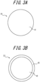
- FIG. 3A is a cross-sectional view of the metal fiber 22 configuring the reinforcement layer 21.
- the metal fiber 22 is configured by steel, copper, aluminum, nickel, or an alloy including any of these.
- the metal fiber 22 illustrated in FIG. 3A is formed from a wire 41 composed of the above-described metal materials.
- the metal fibers 22 configuring the reinforcement layer 21 are preferably formed from brass. In this way, the adhesiveness to the surrounding cover rubber 5 is enhanced as compared not only to organic fibers but also to metal fibers formed from the other metal materials described above, and the concentration of sheer stress at the cover rubber 5 near the reinforcement layer 21 can be further suppressed.
- the surface of the metal fiber 22 can be configured as a coating film 33 formed from a binary alloy of copper and zinc, or a ternary alloy of copper, zinc, and cobalt, as illustrated in FIG. 3B .
- the metal fiber 22 illustrated in FIG. 3B is configured by a wire 42 as the base material and a coating film 43 laminated on the surface of the wire 42.
- the method of forming such a film 43 is not particularly limited but may, for example, be electrolytic treatment by binary alloy plating or ternary alloy plating, or a method of alloying by heat treatment after penetrating in copper plating and zinc plating baths to perform laminated plating treatment.
- the density of the non-woven fabric configuring the reinforcement layer 21 is preferably 100 g/m 2 to 900 g/m 2 and in particular is preferably 200 g/m 2 to 600 g/m 2 .
- the density of the non-woven fabric configuring the reinforcement layer 21 refers to the mass per unit area as measured in accordance with ISO 9073-1. Specifically, the density of the non-woven fabric configuring the reinforcement layer 21 can be calculated by removing the non-woven fabric from the tire 1, melting or incinerating the rubber to remove the rubber, and then weighing the non-woven fabric itself and calculating the density.
- the diameter of the filament configuring the reinforcement layer 21 is preferably 10 ⁇ m to 75 ⁇ m and in particular is preferably 20 ⁇ m to 50 ⁇ m.
- the area may be replaced by the circular area. In this way, the durability of the tire 1 can be further enhanced, and an excessive increase in weight of the tire 1 can be also suppressed, for the same reasons as for the above-described density of the non-woven fabric.
- the reinforcement layer 21 and the ply preferably overlap by 10 mm or more in a ply extension direction orthogonal to the ply thickness direction.
- the reinforcement layer 21 and the turn-up portion 4b of the carcass ply 4 in the present embodiment have an overlap region L of 10 mm or more in the carcass ply extension direction (the same direction as the cord extension direction D of the ply cords of the turn-up portion 4b) that is orthogonal to the carcass ply thickness direction.
- the overlap region L is more preferably 20 mm to 60 mm.
- the extending length of the reinforcement layer 21 along the turn-up portion 4b of the carcass ply 4 is preferably 10 mm or more, more preferably 20 mm or more, and in particular preferably 30 mm or more.
- the reinforcement layer 21 is more easily sandwiched between the rim flange portion 2b and the turn-up portion 4b of the carcass ply 4.
- the extending length of the reinforcement layer 21 along the turn-up portion 4b of the carcass ply 4 is preferably 80 mm or less.
- the outer edge 21a1, in the tire radial direction B, of the reinforcement layer 21 of the present embodiment is located father inward in the tire radial direction B than the outer edge 4b 1 of the turn-up portion 4b in the tire radial direction B, but this configuration is not limiting.
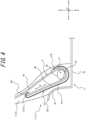
- FIG. 4 illustrates a reinforcement layer 121 as a variation of the reinforcement layer 21.
- the outer edge 21a1 of the reinforcement layer 121 in the tire radial direction B may be located father outward in the tire radial direction B than the outer edge 4b1 of the turn-up portion 4b in the tire radial direction B.
- the reinforcement layer 121 covers the outer edge 4b1 of the turn-up portion 4b from the outer side in the tire width direction A, thereby relieving the stress concentration due to the difference in rigidity from the surrounding cover rubber 5 at the position of the outer edge 4b1 of the turn-up portion 4b.
- the reinforcement layer 121 illustrated in FIG. 4 not only covers the outer edge 4b1 of the turn-up portion 4b from the outer side in the tire width direction A but is also turned up in a U-shape so as to cover the outer edge 4b1 from both the outer side in the tire radial direction B and the inner side in the tire width direction A.
- this configuration is not limiting.
- the first test piece was a test piece in which nothing was disposed along the steel fibers ("Test piece X1" in Table 1 below).
- the second test piece was a test piece in which organic fibers were disposed along the steel fibers ("Test piece X2" in Table 1 below).
- the organic fibers used were nylon 6, with a mass of 470 dtex/1, and a number of embedded fibers equivalent to 78 fibers/5 cm.
- the third test piece was a test piece in which a brass non-woven fabric was disposed along the steel fibers ("Test piece X3" in Table 1 below).
- the brass used was C2680, the filament diameter of the non-woven fabric was 25 ⁇ m, and the density was 300 g/m2.
- Reinforcement Crack length (index) Test piece X1 none 1.0 Test piece X2 organic fibers (nylon 6, 470 dtex/1, 78 fibers/5 cm) 0.8 Test piece X3 brass non-woven fabric 0.4
- the present disclosure relates to a pneumatic tire.
Landscapes
- Engineering & Computer Science (AREA)
- Mechanical Engineering (AREA)
- Tires In General (AREA)
Abstract
Description
- The present disclosure relates to a pneumatic tire.
- Conventionally, a pneumatic tire provided with a carcass ply extending between a pair of bead cores is known. The carcass ply has a turn-up portion that is formed by turning the carcass ply up around the bead core from the inside to the outside in the tire width direction. Patent Literature (PTL) 1 and 2 disclose a pneumatic tire having a reinforcement layer, made of organic fibers, arranged outward in the tire width direction from the turn-up portion of the carcass ply.
-
- PTL 1:
JP 2012-46155 A - PTL 2:
JP 2015-63172 A - During compression deformation of the pneumatic tire, such as when traveling on a road surface, the tire widthwise outer surface of the bead portion of the pneumatic tire is pressed by the rim flange of the rim to which it is assembled. As a result, the cover rubber on the outer side of the bead portion in the tire width direction is sandwiched between the turn-up portion of the carcass ply and the rim flange portion of the rim to be compressed and deformed, so that a portion thereof moves along the turn-up portion of the carcass ply. Therefore, shear strain along the turn-up portion is concentrated in the cover rubber near the turn-up portion. Provision of the reinforcement layer described in
PTL PTL - It is an aim of the present disclosure to provide a pneumatic tire capable of suppressing the concentration of shear strain along the reinforcement layer in the cover rubber near the reinforcement layer.
- A pneumatic tire in a first aspect of the present disclosure includes a pair of bead cores, a carcass ply including a main body positioned between the bead cores and a turn-up portion connected to the main body and formed by turning up around each bead core from inside to outside in a tire width direction, a cover rubber covering the main body of the carcass ply and an outer side of the turn-up portion in the tire width direction and configuring a tire outer surface, and a reinforcement layer located inward from the tire outer surface of the cover rubber and covering an outer side, in the tire width direction, of at least a portion of the turn-up portion of the carcass ply, wherein the reinforcement layer is configured by a non-woven fabric including metal fibers or a rubber sheet material having metal fibers embedded therein.
- According to the present disclosure, a pneumatic tire capable of suppressing the concentration of shear strain along the reinforcement layer in the cover rubber near the reinforcement layer can be provided.
- In the accompanying drawings:
-
FIG. 1 is a tire widthwise cross-sectional view of a pneumatic tire as an embodiment of the present disclosure; -
FIG. 2 is a tire widthwise cross-sectional view illustrating an enlargement of the area near a bead portion in the pneumatic tire illustrated inFIG. 1 , which is mounted on an applicable rim and compressed and deformed in the tire radial direction; -
FIG. 3A is a cross-sectional view of metal fibers forming a reinforcement layer of the pneumatic tire illustrated inFIG. 1 ; -
FIG. 3B is a cross-sectional view of a variation of the metal fibers illustrated inFIG. 3A ; and -
FIG. 4 is a diagram illustrating a variation of the reinforcement layer illustrated inFIG. 1 . - Embodiments of a pneumatic tire according to the present disclosure are described below with reference to the drawings. Configurations that are common across drawings are labeled with the same reference signs.
- Hereafter, unless otherwise specified, the dimensions, length relationships, positional relationships, and the like of each element are assumed to be measured in a reference state in which the pneumatic tire is mounted on an applicable rim, filled to a prescribed internal pressure, and under no load.
- The "applicable rim" refers to a standard rim designated in the following standards in accordance with tire size ("Design Rim" in the YEAR BOOK of the Tire and Rim Association, Inc. (TRA), and "Measuring Rim" in the STANDARDS MANUAL of the European Tyre and Rim Technological Organisation (ETRTO)). The standards are determined according to an effective industrial standard in areas where the tire is produced or used. Examples of the standards include the YEAR BOOK of the TRA in the USA, the STANDARDS MANUAL of the ETRTO in Europe, and the JATMA YEAR BOOK of the Japan Automobile Tyre Manufacturers Association (JATMA) in Japan.
- The "applicable rim" includes sizes that could be included in the future in the aforementioned industrial standards, in addition to current sizes. Examples of the sizes that could be described in the future in the aforementioned industrial standards include the sizes described under FUTURE DEVELOPMENTS in the ETRTO 2013 edition. In the case of a size not listed in the aforementioned industrial standards, the "applicable rim" refers to a rim whose width corresponds to the bead width of the pneumatic tire.
- The "prescribed internal pressure" refers to the air pressure (maximum air pressure) corresponding to the maximum load capability of a single wheel for the applicable size/ply rating in the aforementioned JATMA YEAR BOOK or the like. In the case of a size not described in the aforementioned industrial standards, the "prescribed internal pressure" refers to the air pressure (maximum air pressure) corresponding to the maximum load capability prescribed for each vehicle on which the tire is mounted. The "maximum load" described below refers to the tire maximum load capability specified in the aforementioned standards, such as JATMA, for tires of the applicable size, or in the case of sizes not specified in the aforementioned industrial standards, the "maximum load" refers to the load corresponding to the maximum load capability specified for each vehicle on which the tire is mounted.
-
FIG. 1 illustrates a pneumatic tire 1 (hereinafter simply referred to as "tire 1") according to the present disclosure. Specifically,FIG. 1 is a cross-sectional view of thetire 1, in a cross-section parallel to the tire width direction A and including the tire center axis, in the reference state in which thetire 1 is mounted on an applicable rim, filled to the prescribed internal pressure, and under no load. Hereafter, this cross-section is referred to as the "tire widthwise cross-section". Since thetire 1 has a symmetrical configuration with respect to the tire equatorial plane CL,FIG. 1 illustrates a tire widthwise cross-section on only one side of tire equatorial plane CL in the tire width direction A. However, the tire may have an asymmetrical configuration with respect to the tire equatorial plane CL. -
FIG. 2 is a tire widthwise cross-sectional view illustrating an enlargement of the area near abead portion 1c in thetire 1 illustrated inFIG. 1 when thetire 1 is mounted on anapplicable rim 2.FIG. 2 illustrates thetire 1 as compressed and deformed in the tire radial direction, for example when traveling on a road surface. Theapplicable rim 2 of the present embodiment illustrated inFIG. 2 includes arim seat portion 2a, to which thebead core 3, described below, of thetire 1 is attached on the outside in a tire radial direction B, and arim flange portion 2b protruding outward in the tire radial direction B from both ends of therim seat portion 2a in the tire width direction A. As illustrated inFIG. 2 , when thetire 1 is compressed and deformed in the tire radial direction B, thebead portion 1c of thetire 1 is pressed inward in the tire width direction A by therim flange portion 2b. - As illustrated in
FIG. 1 , thetire 1 includes atread portion 1a, a pair ofsidewall portions 1b extending from both ends of thetread portion 1a in the tire width direction A inward in the tire radial direction B, and a pair ofbead portions 1c provided at the inner ends of thesidewall portions 1b in the tire radial direction B. Thetire 1 is a radial tire and has a configuration suitable for use as a pneumatic tire for trucks, buses, and other heavy load vehicles. Herein, the "tread portion 1a" refers to the portion sandwiched by tread ends TE on both sides in the tire width direction A. The "bead portion 1c" refers to the portion in the tire radial direction B near where the below-describedbead core 3 is located. The "sidewall portion 1b" refers to the portion between thetread portion 1a and thebead portion 1c. The "tread edge TE" refers to the outermost position of the contact patch in the tire width direction when the tire is mounted on the above-described applicable rim, filled to the above-described prescribed internal pressure, and placed under the maximum load. - Furthermore, the outer surface of the tire includes the outer surface of the
tread portion 1a, which is the surface on the outer side of thetread portion 1a in the tire radial direction B, the outer surface of thesidewall portion 1b, which is the surface on the outer side of thesidewall portion 1b in the tire width direction A, and the outer surface of thebead portion 1c, which is the surface on the outer side of thebead portion 1c in the tire width direction A. The tire outer surface is configured by acover rubber 5 formed bytread rubber 10 andside rubber 11. - The
tire 1 includes thebead cores 3, acarcass ply 4, four layers ofbelt plies 6 to 9,tread rubber 10 andside rubber 11 ascover rubber 5, aninner liner 12, and areinforcement layer 21. - The
bead core 3 is embedded in thebead portion 1c. Thetire 1 may be further provided with a rubber bead filler located outward from thebead core 3 in the tire radial direction B. Thebead core 3 includes a plurality of bead cords that are coated by rubber. The bead cords are formed by steel cords. The steel cords can, for example, be made of steel monofilaments or twisted wires. - The carcass ply 4 extends toroidally to straddle the pair of
bead portions 1c, more specifically to straddle the pair ofbead cores 3. The carcass ply 4 of the present embodiment has a radial structure. - Specifically, the
carcass ply 4 extends toroidally across the pair ofbead cores 3 and is folded from inside to outside in the tire width direction A around eachbead core 3. The carcass ply 4 includes a plurality of ply cords arranged in parallel to each other and coating rubber that covers the plurality of ply cords. Instead of including the coating rubber, however, thecarcass ply 4 may be configured by, for example, arranging a plurality of ply cords that are made of brass, or plated with a material including brass, in parallel and bonding adjacent ply cords. Thetire 1 in the present embodiment includes onecarcass ply 4 but may instead include two or more carcass plies 4. The plurality of ply cords of thecarcass ply 4 are arranged at an angle of, for example, 75° to 90° with respect to the tire circumferential direction C. The ply cords of the carcass ply 4 can be metal cords, such as steel cords. The steel cords can be made of steel monofilaments or twisted wires with, for example, a brass coating on the surface. The ply cords may also be organic fiber cords, for example, with a brass coating on the surface. - More specifically, the
carcass ply 4 has amain body 4a located between the pair ofbead cores 3 and a turn-upportion 4b that is formed by being connected to themain body 4a and turned up from inside to outside in the tire width direction A around eachbead core 3. As described above, thetire 1 may further include a bead filler extending while tapering toward the outer side of thebead core 3 in the tire radial direction B. In a case in which thetire 1 includes a bead filler, the bead filler is arranged between themain body 4a and the turn-upportion 4b of thecarcass ply 4. - The belt plies 6 to 9 are disposed in the
tread portion 1a. Specifically, the belt plies 6 to 9 are disposed outside of the carcass ply 4 in the tire radial direction B relative to the crown of thecarcass ply 4. Thetire 1 in the present embodiment includes four layers of belt plies 6 to 9, but the number of layers is not particularly limited as long as at least one layer is provided. Each belt ply 6 to 9 includes a plurality of ply cords arranged in parallel to each other and coating rubber that covers the plurality of ply cords. Instead of including the coating rubber, however, each belt ply 6 to 9 may be configured by, for example, arranging a plurality of ply cords that are made of brass, or plated with a material including brass, in parallel and bonding adjacent ply cords. Each belt ply 6 to 9 forms a sloped belt layer in which the cord cut edges of the ply cords are exposed at both ends in the tire width direction A. The plurality of ply cords in each belt ply 6 to 9 extends at an angle with respect to the tire width direction A and the tire circumferential direction C. For example, the ply cords are arranged to be inclined at an angle of 10° to 60° with respect to the tire circumferential direction C. The ply cords in each belt ply 6 to 9 can be metal cords, such as steel cords. The steel cords can be made of steel monofilaments or twisted wires with, for example, a brass coating on the surface. The ply cords may also be organic fiber cords, for example, with a brass coating on the surface. - One or more of the four layers of belt plies 6 to 9 may be a circumferential belt layer that includes a plurality of ply cords extending along the tire circumferential direction C.
- The
tread rubber 10 covers the crown portion of themain body 4a of thecarcass ply 4 and covers the outer side, in the tire radial direction B, of the four layers of belt plies 6 to 9. The outer surface of thetread portion 1a in the present embodiment is configured by thetread rubber 10. A tread pattern including circumferential grooves extending in the tire circumferential direction C, widthwise grooves extending in the tire width direction A, and the like is formed on the outer surface of thetread portion 1a. - The
side rubber 11 covers the outside, in the tire width direction A, of themain body 4a and the turn-upportion 4b of thecarcass ply 4. The outer surface of thesidewall portion 1b and the outer surface of thebead portion 1c in the present embodiment are configured by theside rubber 11. The outer end of theside rubber 11 in the tire radial direction B is connected to the end of the above-describedtread rubber 10 in the tire width direction A. - In this way, the
tread rubber 10 andside rubber 11 in the present embodiment as a whole form thecover rubber 5 of thetire 1, which covers thecarcass ply 4 and the belt plies 6 to 9 and configures the tire outer surface. - The
inner liner 12 covers the tire inner surface side of themain body 4a of thecarcass ply 4 and configures the tire inner surface of thetire 1. Theinner liner 12 is layered onto the tire inner surface side of themain body 4a of thecarcass ply 4. Theinner liner 12 may, for example, be formed from a butyl-based rubber having low air permeability. Butyl-based rubber refers to butyl rubber and butyl halide rubber, which is a derivative thereof. - As illustrated in
FIGS. 1 and2 , thereinforcement layer 21 is located inward from the tire outer surface of theside rubber 11 of thecover rubber 5 and covers an outer side, in the tire width direction A, of at least a portion of the turn-upportion 4b of thecarcass ply 4. Therefore, as illustrated inFIG. 2 , even if thebead portion 1c of thetire 1 is pressed by therim flange portion 2b, and thecover rubber 5 between therim flange portion 2b and the turn-upportion 4b of thecarcass ply 4 is compressed and deformed, the concentration of shear strain along the turn-upportion 4b in thecover rubber 5 near the turn-upportion 4b can be suppressed. As illustrated inFIG. 2 , thereinforcement layer 21 is configured by a non-woven fabric formed frommetal fibers 22. The modulus of thereinforcement layer 21 in the cord extension direction D of the ply cords of the turn-upportion 4b in thecarcass ply 4 is lower than the modulus of the turn-upportion 4b in the cord extension direction D. As compared to the case in which the reinforcement layer consists of organic fibers, the use of such areinforcement layer 21 can maintain flexibility while improving the adhesiveness with theside rubber 11 as the surroundingcover rubber 5. Therefore, the concentration of shear strain along thereinforcement layer 21 can also be suppressed for thecover rubber 5 near thereinforcement layer 21. - As illustrated in
FIG. 1 , in the tire widthwise cross-sectional view, at least a portion of thereinforcement layer 21 is located in a region RA, in the tire radial direction B, that is from 5% to 30% of the tire section height SH from aninner edge 3a of thebead core 3 in the tire radial direction B outward in the tire radial direction B. The tire section height SH is the length in the tire radial direction B, in the tire widthwise cross-section, from theinner edge 3a of thebead core 3 in the tire radial direction B to the outer edge of thetread rubber 10 in the tire radial direction B (in the present embodiment, the position of the tire equatorial plane CL in the tire width direction A). In this way, when thebead portion 1c is pressed against therim flange portion 2b of theapplicable rim 2, and thecover rubber 5 on the outer side of thebead portion 1c in the tire width direction A is sandwiched between therim flange portion 2b and the turn-upportion 4b of the carcass ply 4 to be compressed and deformed, at least a portion of the above-describedreinforcement layer 21 also tends to be sandwiched between therim flange portion 2b and the turn-upportion 4b of thecarcass ply 4. In other words, in the tire widthwise cross-sectional view (seeFIGS. 1 and2 ), theentire reinforcement layer 21 is prevented from moving together with thecover rubber 5 along the cord extension direction D of the ply cords of the turn-upportion 4b. Consequently, the concentration of shear strain along thereinforcement layer 21 can be better suppressed at thecover rubber 5 near thereinforcement layer 21. - As illustrated in
FIG. 2 , when thetire 1 is mounted on theapplicable rim 2, at least a portion of thereinforcement layer 21 is preferably located farther inward in the tire radial direction B than the position of the outer edge 2b1 of therim flange portion 2b in the tire radial direction B. Thus, in the same way as above, when thebead portion 1c is pressed against therim flange portion 2b of theapplicable rim 2, and thecover rubber 5 on the outer side of thebead portion 1c in the tire width direction A is sandwiched between therim flange portion 2b and the turn-upportion 4b of the carcass ply 4 to be compressed and deformed, at least a portion of the above-describedreinforcement layer 21 also tends to be sandwiched between therim flange portion 2b and the turn-upportion 4b of thecarcass ply 4. Consequently, the concentration of shear strain along thereinforcement layer 21 can be better suppressed at thecover rubber 5 near thereinforcement layer 21. - As illustrated in
FIG. 2 , in the tire widthwise cross-sectional view, thereinforcement layer 21 preferably extends from a position farther outward, in the tire radial direction B, than theouter edge 3b of thebead core 3 in the tire radial direction B to a position farther inward on the outer side, in the tire width direction A, of the turn-upportion 4b. In other words, in thereinforcement layer 21, the reinforcementmain body 21a that is located farther outward in the tire width direction A than the turn-upportion 4b of the carcass ply 4 preferably extends in the tire radial direction B across a position P2, in the tire radial direction B, of theouter edge 3b of thebead core 3. In this way, when thebead portion 1c is pressed against therim flange portion 2b of theapplicable rim 2, and thecover rubber 5 on the outer side of thebead portion 1c in the tire width direction A is sandwiched between therim flange portion 2b and the turn-upportion 4b of the carcass ply 4 to be compressed and deformed, at least a portion of the reinforcementmain body 21a of thereinforcement layer 21 also tends to be sandwiched between therim flange portion 2b and the turn-upportion 4b of thecarcass ply 4. Consequently, the concentration of shear strain along thereinforcement layer 21 can be better suppressed at thecover rubber 5 near thereinforcement layer 21. - Furthermore, as illustrated in
FIG. 2 , in the tire widthwise cross-sectional view, thereinforcement layer 21 is preferably turned up around thebead core 3 from the outer side towards the inner side in the tire width direction A. In other words, in thereinforcement layer 21, the portion of the reinforcementmain body 21a in the tire radial direction B located father outward in the tire width direction A than the turn-upportion 4b of thecarcass ply 4 is preferably wrapped around thebead core 3 and is preferably wrapped up farther outward, in the tire radial direction B, than a position P1, in the tire radial direction B, of theinner edge 3a of thebead core 3. In this way, when thebead portion 1c is pressed against therim flange portion 2b of theapplicable rim 2, and thecover rubber 5 on the outer side of thebead portion 1c in the tire width direction A is sandwiched between therim flange portion 2b and the turn-upportion 4b of the carcass ply 4 to be compressed and deformed, thereinforcement layer 21 can be further prevented from moving together with thecover rubber 5 along the cord extension direction D of the ply cords of the turn-upportion 4b. Consequently, the concentration of shear strain along thereinforcement layer 21 can be better suppressed at thecover rubber 5 near thereinforcement layer 21. - Furthermore, in the
reinforcement layer 21, the reinforcementmain body 21a formed by being turned up around thebead core 3 from the outer side towards the inner side in the tire width direction A is more preferably wrapped up farther outward, in the tire radial direction B, than theouter edge 3b of thebead core 3 in the tire widthwise cross-sectional view (seeFIG. 2 ). In this way, thereinforcement layer 21 is even further prevented from moving together with thecover rubber 5 along the cord extension direction D of the ply cords of the turn-upportion 4b. Therefore, the concentration of shear strain along thereinforcement layer 21 can be even further suppressed at thecover rubber 5 near thereinforcement layer 21. - The
reinforcement layer 21 configured by a non-woven fabric formed frommetal fibers 22 can be manufactured by various methods, and the manufacturing method is not limited. For example, a needle punch can be used to entanglemetal fibers 22, obtained by various cutting methods, into a felt-like shape. The diameter of themetal fibers 22 can be changed by changing the amount of cutting, for example. The thickness and density of the non-woven fabric formed from themetal fibers 22 can be changed by, for example, changing the amount ofmetal fibers 22 that are punched and changing the number of vertical movements per unit time during needle punching. - The
reinforcement layer 21 in the present embodiment is configured by a non-woven fabric formed frommetal fibers 22, but this configuration is not limiting. Thereinforcement layer 21 may be configured by a rubber sheet material in which themetal fibers 22 are embedded. However, thereinforcement layer 21 is preferably configured by a non-woven fabric, as in the present embodiment. By thereinforcement layer 21 being a non-woven fabric, the edges of themetal fibers 22 tend not to be exposed on the outer surface of thereinforcement layer 21, and the occurrence of cracks in the surrounding rubber can be suppressed. -
FIG. 3A is a cross-sectional view of themetal fiber 22 configuring thereinforcement layer 21. Themetal fiber 22 is configured by steel, copper, aluminum, nickel, or an alloy including any of these. In other words, themetal fiber 22 illustrated inFIG. 3A is formed from awire 41 composed of the above-described metal materials. In particular, themetal fibers 22 configuring thereinforcement layer 21 are preferably formed from brass. In this way, the adhesiveness to thesurrounding cover rubber 5 is enhanced as compared not only to organic fibers but also to metal fibers formed from the other metal materials described above, and the concentration of sheer stress at thecover rubber 5 near thereinforcement layer 21 can be further suppressed. However, instead of themetal fiber 22 itself being formed from brass, the surface of themetal fiber 22 can be configured as a coating film 33 formed from a binary alloy of copper and zinc, or a ternary alloy of copper, zinc, and cobalt, as illustrated inFIG. 3B . Themetal fiber 22 illustrated inFIG. 3B is configured by awire 42 as the base material and acoating film 43 laminated on the surface of thewire 42. The method of forming such afilm 43 is not particularly limited but may, for example, be electrolytic treatment by binary alloy plating or ternary alloy plating, or a method of alloying by heat treatment after penetrating in copper plating and zinc plating baths to perform laminated plating treatment. - The density of the non-woven fabric configuring the
reinforcement layer 21 is preferably 100 g/m2 to 900 g/m2 and in particular is preferably 200 g/m2 to 600 g/m2. When the density of the non-woven fabric configuring thereinforcement layer 21 is in the above range, the concentration of sheer stress at thecover rubber 5 near thereinforcement layer 21 can be further suppressed. Consequently, the durability of thetire 1 can be further improved. Furthermore, when the density of the non-woven fabric configuring thereinforcement layer 21 is in the above range, an excessive increase in the weight of thetire 1 due to thereinforcement layer 21 can also be suppressed. The density of the non-woven fabric configuring thereinforcement layer 21 refers to the mass per unit area as measured in accordance with ISO 9073-1. Specifically, the density of the non-woven fabric configuring thereinforcement layer 21 can be calculated by removing the non-woven fabric from thetire 1, melting or incinerating the rubber to remove the rubber, and then weighing the non-woven fabric itself and calculating the density. - Furthermore, the diameter of the filament configuring the
reinforcement layer 21 is preferably 10 µm to 75 µm and in particular is preferably 20 µm to 50 µm. In a case in which the cross-section is rectangular, the area may be replaced by the circular area. In this way, the durability of thetire 1 can be further enhanced, and an excessive increase in weight of thetire 1 can be also suppressed, for the same reasons as for the above-described density of the non-woven fabric. - As illustrated in
FIG. 1 , in the tire widthwise cross-sectional view, thereinforcement layer 21 and the ply preferably overlap by 10 mm or more in a ply extension direction orthogonal to the ply thickness direction. Specifically, as illustrated inFIG. 1 , thereinforcement layer 21 and the turn-upportion 4b of the carcass ply 4 in the present embodiment have an overlap region L of 10 mm or more in the carcass ply extension direction (the same direction as the cord extension direction D of the ply cords of the turn-upportion 4b) that is orthogonal to the carcass ply thickness direction. The overlap region L is more preferably 20 mm to 60 mm. By the overlap region L being 10 mm or more, the durability of thetire 1 can be further enhanced, and an excessive increase in weight of thetire 1 can be also suppressed, for the same reasons as for the above-described density of the non-woven fabric. - In the tire widthwise cross-sectional view (see
FIGS. 1 and2 ), the extending length of thereinforcement layer 21 along the turn-upportion 4b of thecarcass ply 4 is preferably 10 mm or more, more preferably 20 mm or more, and in particular preferably 30 mm or more. In this way, when thetire 1 is compressed and deformed in the tire radial direction B, thereinforcement layer 21 is more easily sandwiched between therim flange portion 2b and the turn-upportion 4b of thecarcass ply 4. From the viewpoint of suppressing an excessive increase in weight, the extending length of thereinforcement layer 21 along the turn-upportion 4b of thecarcass ply 4 is preferably 80 mm or less. - As illustrated in
FIGS. 1 and2 , the outer edge 21a1, in the tire radial direction B, of thereinforcement layer 21 of the present embodiment is located father inward in the tire radial direction B than theouter edge 4bportion 4b in the tire radial direction B, but this configuration is not limiting.FIG. 4 illustrates areinforcement layer 121 as a variation of thereinforcement layer 21. As illustrated inFIG. 4 , the outer edge 21a1 of thereinforcement layer 121 in the tire radial direction B may be located father outward in the tire radial direction B than the outer edge 4b1 of the turn-upportion 4b in the tire radial direction B. In this way, thereinforcement layer 121 covers the outer edge 4b1 of the turn-upportion 4b from the outer side in the tire width direction A, thereby relieving the stress concentration due to the difference in rigidity from the surroundingcover rubber 5 at the position of the outer edge 4b1 of the turn-upportion 4b. Thereinforcement layer 121 illustrated inFIG. 4 not only covers the outer edge 4b1 of the turn-upportion 4b from the outer side in the tire width direction A but is also turned up in a U-shape so as to cover the outer edge 4b1 from both the outer side in the tire radial direction B and the inner side in the tire width direction A. However, this configuration is not limiting. - Next, an overview, along with the results, of a verification test conducted to verify the above-described effects of the
reinforcement layer 21 are described. In this verification test, three test pieces in which a plurality of steel fibers were embedded in rubber were subjected to a load by repeatedly pressing cylindrical protrusions, with a tip radius of 10 mm and a width of 30 mm, from a vertical direction orthogonal to the extension direction of the steel fibers at a minimum load of -0.2 kN, a maximum load of -4 kN, and at an ambient temperature of 70°C. For each test piece, the lengths of cracks occurring in the steel fibers after 2 × 10⁶ cycles of the aforementioned load were compared as an index, as illustrated in Table 1 below. The first test piece was a test piece in which nothing was disposed along the steel fibers ("Test piece X1" in Table 1 below). The second test piece was a test piece in which organic fibers were disposed along the steel fibers ("Test piece X2" in Table 1 below). The organic fibers used werenylon 6, with a mass of 470 dtex/1, and a number of embedded fibers equivalent to 78 fibers/5 cm. The third test piece was a test piece in which a brass non-woven fabric was disposed along the steel fibers ("Test piece X3" in Table 1 below). The brass used was C2680, the filament diameter of the non-woven fabric was 25 µm, and the density was 300 g/m2.[Table 1] Reinforcement Crack length (index) Test piece X1 none 1.0 Test piece X2 organic fibers ( nylon 6, 470 dtex/1, 78 fibers/5 cm)0.8 Test piece X3 brass non-woven fabric 0.4 - The pneumatic tire according to the present disclosure is not limited to the specific configurations described in the above embodiments. Various modifications and changes may be made without departing from the scope of the claims.
- The present disclosure relates to a pneumatic tire.
-
- 1
- Pneumatic tire
- 1a
- Tread portion
- 1b
- Sidewall portion
- 1c
- Bead portion
- 2
- Applicable rim
- 2a
- Rim seat portion
- 2b
- Rim flange portion
- 2b1
- Outer edge of rim flange portion
- 3
- Bead core
- 3a
- Inner edge of bead core
- 3b
- Outer edge of bead core
- 4
- Carcass ply
- 4a
- Main body
- 4b
- Turn-up portion
- 4b1
- Outer edge of turn-up portion
- 5
- Cover rubber
- 6 to 9
- Belt ply
- 10
- Tread rubber
- 11
- Side rubber (cover rubber)
- 12
- Inner liner
- 21, 121
- Reinforcement layer
- 21a
- Reinforcement main body
- 21a1
- Outer edge of reinforcement layer
- 21b
- Reinforcement turn-up portion
- 22
- Metal fiber
- 41, 42
- Wire rod
- 43
- Coating film
- A
- Tire width direction
- B
- Tire radial direction
- C
- Tire circumferential direction
- D
- Cord extension direction
- CL
- Tire equatorial plane
- L
- Overlap region
- P1
- Position of inner edge of bead core in tire radial direction
- P2
- Position of outer edge of bead core in tire radial direction
- RA
- Region from 5% to 30% of tire section height from inner edge of bead core outward in tire radial direction
- SH
- Tire section height
- TE
- Tread edge
Claims (10)
- A pneumatic tire comprising:a pair of bead cores;a carcass ply comprising a main body positioned between the bead cores and a turn-up portion connected to the main body and formed by turning up around each bead core from inside to outside in a tire width direction;a cover rubber covering the main body of the carcass ply and an outer side of the turn-up portion in the tire width direction and configuring a tire outer surface; anda reinforcement layer located inward from the tire outer surface of the cover rubber and covering an outer side, in the tire width direction, of at least a portion of the turn-up portion of the carcass ply, whereinthe reinforcement layer is configured bya non-woven fabric comprising metal fibers, ora rubber sheet material having metal fibers embedded therein.
- The pneumatic tire according to claim 1, wherein in a tire widthwise cross-sectional view, at least a portion of the reinforcement layer is located in a region, in a tire radial direction, that is from 5% to 30% of a tire section height from an inner edge of the bead core in the tire radial direction outward in the tire radial direction.
- The pneumatic tire according to claim 2, wherein in the tire widthwise cross-sectional view, the reinforcement layer extends from a position farther outward, in the tire radial direction, than an outer edge of the bead core in the tire radial direction to a position farther inward.
- The pneumatic tire according to claim 3, wherein in the tire widthwise cross-sectional view, the reinforcement layer is turned up around the bead core from an outer side towards an inner side in the tire width direction.
- The pneumatic tire according to any one of claims 1 to 4, wherein the metal fibers comprise steel, copper, aluminum, nickel, or an alloy including any of these.
- The pneumatic tire according to claim 5, wherein the metal fibers comprise brass.
- The pneumatic tire according to any one of claims 1 to 4, wherein a surface of the metal fibers is configured by a coating film comprising a binary alloy of copper and zinc or a ternary alloy of copper, zinc, and cobalt.
- The pneumatic tire according to any one of claims 1 to 7, whereinthe reinforcement layer is a non-woven fabric configured by metal fibers, anda density of the non-woven fabric is from 100 g/m2 to 900 g/m2.
- The pneumatic tire according to any one of claims 1 to 8, whereinthe reinforcement layer is a non-woven fabric configured by metal fibers, anda filament diameter of the non-woven fabric is from 10 µm to 75 µm.
- The pneumatic tire according to any one of claims 1 to 9, wherein in a tire widthwise cross-sectional view, the reinforcement layer and the turn-up portion of the carcass ply overlap by 10 mm or more along a ply extension direction orthogonal to a ply thickness direction.
Applications Claiming Priority (2)
| Application Number | Priority Date | Filing Date | Title |
|---|---|---|---|
| JP2020092586A JP7333289B2 (en) | 2020-05-27 | 2020-05-27 | pneumatic tire |
| PCT/JP2021/000566 WO2021240863A1 (en) | 2020-05-27 | 2021-01-08 | Pneumatic tire |
Publications (2)
| Publication Number | Publication Date |
|---|---|
| EP4159480A1 true EP4159480A1 (en) | 2023-04-05 |
| EP4159480A4 EP4159480A4 (en) | 2023-12-27 |
Family
ID=78744184
Family Applications (1)
| Application Number | Title | Priority Date | Filing Date |
|---|---|---|---|
| EP21812215.8A Pending EP4159480A4 (en) | 2020-05-27 | 2021-01-08 | Pneumatic tire |
Country Status (5)
| Country | Link |
|---|---|
| US (1) | US20230271460A1 (en) |
| EP (1) | EP4159480A4 (en) |
| JP (1) | JP7333289B2 (en) |
| CN (1) | CN115485151B (en) |
| WO (1) | WO2021240863A1 (en) |
Family Cites Families (21)
| Publication number | Priority date | Publication date | Assignee | Title |
|---|---|---|---|---|
| JP3673026B2 (en) * | 1996-09-03 | 2005-07-20 | 住友ゴム工業株式会社 | Pneumatic tire |
| JP4293658B2 (en) * | 1998-11-11 | 2009-07-08 | 株式会社ブリヂストン | Heavy duty pneumatic radial tire |
| JP2005153591A (en) * | 2003-11-21 | 2005-06-16 | Sumitomo Rubber Ind Ltd | Motorcycle tire for off-road |
| JP2005271638A (en) * | 2004-03-23 | 2005-10-06 | Bridgestone Corp | Pneumatic tire |
| JP2006347394A (en) * | 2005-06-16 | 2006-12-28 | Sumitomo Rubber Ind Ltd | Pneumatic tire |
| EP2077194B1 (en) * | 2006-10-20 | 2012-01-04 | Bridgestone Corporation | Pneumatic tire |
| WO2011142389A1 (en) * | 2010-05-11 | 2011-11-17 | 株式会社ブリヂストン | Pneumatic tire |
| JP5893824B2 (en) * | 2010-08-30 | 2016-03-23 | 横浜ゴム株式会社 | Pneumatic radial tire |
| JP6194151B2 (en) * | 2011-01-19 | 2017-09-06 | 株式会社ブリヂストン | Pneumatic tire |
| JP2012245655A (en) * | 2011-05-25 | 2012-12-13 | Bridgestone Corp | Method of manufacturing pneumatic tire and pneumatic tire |
| JP6013908B2 (en) * | 2012-12-28 | 2016-10-25 | 住友ゴム工業株式会社 | Heavy duty tire |
| JP6087776B2 (en) * | 2013-09-24 | 2017-03-01 | 東洋ゴム工業株式会社 | Pneumatic semi-radial tire |
| JP2015227138A (en) * | 2014-06-02 | 2015-12-17 | 株式会社ブリヂストン | Pneumatic tire |
| JP6293602B2 (en) * | 2014-07-17 | 2018-03-14 | 東洋ゴム工業株式会社 | Pneumatic tire and manufacturing method thereof |
| JP6509519B2 (en) * | 2014-10-08 | 2019-05-08 | Toyo Tire株式会社 | Pneumatic tire |
| JP2016165923A (en) * | 2015-03-09 | 2016-09-15 | 株式会社ブリヂストン | Pneumatic tire |
| JP6742890B2 (en) * | 2016-11-28 | 2020-08-19 | Toyo Tire株式会社 | Pneumatic tire |
| JP6790845B2 (en) * | 2017-01-13 | 2020-11-25 | 住友ゴム工業株式会社 | Pneumatic tires for heavy loads |
| JP6930262B2 (en) * | 2017-07-18 | 2021-09-01 | 横浜ゴム株式会社 | Pneumatic tires and manufacturing methods for pneumatic tires |
| JP6921668B2 (en) * | 2017-07-19 | 2021-08-18 | 株式会社ブリヂストン | Pneumatic tires |
| JP2020037330A (en) * | 2018-09-04 | 2020-03-12 | 株式会社ブリヂストン | Pneumatic tire |
-
2020
- 2020-05-27 JP JP2020092586A patent/JP7333289B2/en active Active
-
2021
- 2021-01-08 US US17/997,660 patent/US20230271460A1/en active Pending
- 2021-01-08 CN CN202180032142.4A patent/CN115485151B/en active Active
- 2021-01-08 EP EP21812215.8A patent/EP4159480A4/en active Pending
- 2021-01-08 WO PCT/JP2021/000566 patent/WO2021240863A1/en unknown
Also Published As
| Publication number | Publication date |
|---|---|
| CN115485151B (en) | 2024-05-03 |
| WO2021240863A1 (en) | 2021-12-02 |
| US20230271460A1 (en) | 2023-08-31 |
| JP2021187237A (en) | 2021-12-13 |
| CN115485151A (en) | 2022-12-16 |
| EP4159480A4 (en) | 2023-12-27 |
| JP7333289B2 (en) | 2023-08-24 |
Similar Documents
| Publication | Publication Date | Title |
|---|---|---|
| EP3059102B1 (en) | Pneumatic tire | |
| JP5312233B2 (en) | Pneumatic tire | |
| EP2796300A1 (en) | Pneumatic tire for heavy loads | |
| JPWO2015093440A1 (en) | Pneumatic tire and manufacturing method thereof | |
| US9440406B2 (en) | Pneumatic tire and method of forming circumferential belt layer of the same | |
| EP2853419B1 (en) | Pneumatic tire | |
| EP2803505B1 (en) | Heavy duty pneumatic tire | |
| JP6015450B2 (en) | Pneumatic tire | |
| JP6343170B2 (en) | Pneumatic tire | |
| EP2610074A1 (en) | Pneumatic radial aircraft tire | |
| EP3805016A1 (en) | Pneumatic tire | |
| JP5682210B2 (en) | Pneumatic tire | |
| CN104114376A (en) | Pneumatic tire for two-wheeled motor vehicle | |
| EP4159480A1 (en) | Pneumatic tire | |
| EP2998128B1 (en) | Pneumatic tire | |
| EP4159481A1 (en) | Pneumatic tire | |
| JP4279018B2 (en) | Pneumatic tire | |
| CN110770011A (en) | Method for manufacturing pneumatic tire | |
| US20210394563A1 (en) | Tire | |
| CN112638665A (en) | Pneumatic tire and method for manufacturing pneumatic tire | |
| JP2018202997A (en) | Pneumatic tire | |
| US20220314712A1 (en) | Tire | |
| EP3805015A1 (en) | Pneumatic tire | |
| CN112912260A (en) | Pneumatic tire | |
| CN113226797A (en) | Pneumatic tire for aircraft |
Legal Events
| Date | Code | Title | Description |
|---|---|---|---|
| STAA | Information on the status of an ep patent application or granted ep patent |
Free format text: STATUS: THE INTERNATIONAL PUBLICATION HAS BEEN MADE |
|
| PUAI | Public reference made under article 153(3) epc to a published international application that has entered the european phase |
Free format text: ORIGINAL CODE: 0009012 |
|
| STAA | Information on the status of an ep patent application or granted ep patent |
Free format text: STATUS: REQUEST FOR EXAMINATION WAS MADE |
|
| 17P | Request for examination filed |
Effective date: 20221125 |
|
| AK | Designated contracting states |
Kind code of ref document: A1 Designated state(s): AL AT BE BG CH CY CZ DE DK EE ES FI FR GB GR HR HU IE IS IT LI LT LU LV MC MK MT NL NO PL PT RO RS SE SI SK SM TR |
|
| DAV | Request for validation of the european patent (deleted) | ||
| DAX | Request for extension of the european patent (deleted) | ||
| A4 | Supplementary search report drawn up and despatched |
Effective date: 20231123 |
|
| RIC1 | Information provided on ipc code assigned before grant |
Ipc: B60C 15/06 20060101ALI20231117BHEP Ipc: B60C 9/00 20060101AFI20231117BHEP |