EP4159409A1 - Method for controlling cyclic production of containers by stretch blow moulding - Google Patents
Method for controlling cyclic production of containers by stretch blow moulding Download PDFInfo
- Publication number
- EP4159409A1 EP4159409A1 EP22207519.4A EP22207519A EP4159409A1 EP 4159409 A1 EP4159409 A1 EP 4159409A1 EP 22207519 A EP22207519 A EP 22207519A EP 4159409 A1 EP4159409 A1 EP 4159409A1
- Authority
- EP
- European Patent Office
- Prior art keywords
- blowing
- pressure
- machine
- instant
- preform
- Prior art date
- Legal status (The legal status is an assumption and is not a legal conclusion. Google has not performed a legal analysis and makes no representation as to the accuracy of the status listed.)
- Pending
Links
- 238000004519 manufacturing process Methods 0.000 title claims abstract description 128
- 238000000034 method Methods 0.000 title claims abstract description 39
- 238000000071 blow moulding Methods 0.000 title claims abstract description 27
- 125000004122 cyclic group Chemical group 0.000 title claims abstract description 14
- 238000007664 blowing Methods 0.000 claims abstract description 357
- 230000033228 biological regulation Effects 0.000 claims abstract description 101
- 230000001105 regulatory effect Effects 0.000 claims abstract description 59
- 230000006641 stabilisation Effects 0.000 claims abstract description 37
- 230000008859 change Effects 0.000 claims abstract description 33
- 238000011105 stabilization Methods 0.000 claims abstract description 29
- 238000012544 monitoring process Methods 0.000 claims abstract description 15
- 239000012530 fluid Substances 0.000 claims description 59
- 230000001276 controlling effect Effects 0.000 claims description 25
- 239000004033 plastic Substances 0.000 claims description 13
- 229920003023 plastic Polymers 0.000 claims description 13
- 230000002123 temporal effect Effects 0.000 claims description 11
- 238000004891 communication Methods 0.000 claims description 10
- 238000004590 computer program Methods 0.000 claims description 8
- 238000004458 analytical method Methods 0.000 claims description 6
- 239000000463 material Substances 0.000 claims description 5
- 230000006870 function Effects 0.000 description 19
- 238000004364 calculation method Methods 0.000 description 13
- 230000004044 response Effects 0.000 description 13
- 238000002347 injection Methods 0.000 description 8
- 239000007924 injection Substances 0.000 description 8
- 238000012986 modification Methods 0.000 description 6
- 230000004048 modification Effects 0.000 description 6
- 230000008569 process Effects 0.000 description 6
- 230000003416 augmentation Effects 0.000 description 5
- 238000003860 storage Methods 0.000 description 5
- 230000001960 triggered effect Effects 0.000 description 5
- 230000003466 anti-cipated effect Effects 0.000 description 4
- 238000009530 blood pressure measurement Methods 0.000 description 4
- 230000003111 delayed effect Effects 0.000 description 4
- 238000005259 measurement Methods 0.000 description 4
- 238000006243 chemical reaction Methods 0.000 description 3
- 238000012937 correction Methods 0.000 description 3
- 238000006073 displacement reaction Methods 0.000 description 3
- 238000009826 distribution Methods 0.000 description 3
- 238000010438 heat treatment Methods 0.000 description 3
- 230000002457 bidirectional effect Effects 0.000 description 2
- 230000007547 defect Effects 0.000 description 2
- 238000010586 diagram Methods 0.000 description 2
- 238000002955 isolation Methods 0.000 description 2
- 239000000203 mixture Substances 0.000 description 2
- 229920000139 polyethylene terephthalate Polymers 0.000 description 2
- 239000005020 polyethylene terephthalate Substances 0.000 description 2
- 238000012545 processing Methods 0.000 description 2
- 230000032683 aging Effects 0.000 description 1
- 238000012550 audit Methods 0.000 description 1
- 230000005540 biological transmission Effects 0.000 description 1
- 230000015556 catabolic process Effects 0.000 description 1
- 230000002950 deficient Effects 0.000 description 1
- 238000006731 degradation reaction Methods 0.000 description 1
- 238000001514 detection method Methods 0.000 description 1
- 238000011161 development Methods 0.000 description 1
- 230000018109 developmental process Effects 0.000 description 1
- 230000000694 effects Effects 0.000 description 1
- 235000021183 entrée Nutrition 0.000 description 1
- 230000001747 exhibiting effect Effects 0.000 description 1
- 230000009477 glass transition Effects 0.000 description 1
- 230000003116 impacting effect Effects 0.000 description 1
- 238000009776 industrial production Methods 0.000 description 1
- 230000010354 integration Effects 0.000 description 1
- 238000012806 monitoring device Methods 0.000 description 1
- -1 polyethylene terephthalate Polymers 0.000 description 1
- 238000003825 pressing Methods 0.000 description 1
- 230000000717 retained effect Effects 0.000 description 1
Images


Classifications
-
- B—PERFORMING OPERATIONS; TRANSPORTING
- B29—WORKING OF PLASTICS; WORKING OF SUBSTANCES IN A PLASTIC STATE IN GENERAL
- B29C—SHAPING OR JOINING OF PLASTICS; SHAPING OF MATERIAL IN A PLASTIC STATE, NOT OTHERWISE PROVIDED FOR; AFTER-TREATMENT OF THE SHAPED PRODUCTS, e.g. REPAIRING
- B29C49/00—Blow-moulding, i.e. blowing a preform or parison to a desired shape within a mould; Apparatus therefor
- B29C49/42—Component parts, details or accessories; Auxiliary operations
- B29C49/78—Measuring, controlling or regulating
-
- B—PERFORMING OPERATIONS; TRANSPORTING
- B29—WORKING OF PLASTICS; WORKING OF SUBSTANCES IN A PLASTIC STATE IN GENERAL
- B29C—SHAPING OR JOINING OF PLASTICS; SHAPING OF MATERIAL IN A PLASTIC STATE, NOT OTHERWISE PROVIDED FOR; AFTER-TREATMENT OF THE SHAPED PRODUCTS, e.g. REPAIRING
- B29C49/00—Blow-moulding, i.e. blowing a preform or parison to a desired shape within a mould; Apparatus therefor
- B29C49/08—Biaxial stretching during blow-moulding
-
- B—PERFORMING OPERATIONS; TRANSPORTING
- B29—WORKING OF PLASTICS; WORKING OF SUBSTANCES IN A PLASTIC STATE IN GENERAL
- B29C—SHAPING OR JOINING OF PLASTICS; SHAPING OF MATERIAL IN A PLASTIC STATE, NOT OTHERWISE PROVIDED FOR; AFTER-TREATMENT OF THE SHAPED PRODUCTS, e.g. REPAIRING
- B29C49/00—Blow-moulding, i.e. blowing a preform or parison to a desired shape within a mould; Apparatus therefor
- B29C49/28—Blow-moulding apparatus
-
- G—PHYSICS
- G05—CONTROLLING; REGULATING
- G05B—CONTROL OR REGULATING SYSTEMS IN GENERAL; FUNCTIONAL ELEMENTS OF SUCH SYSTEMS; MONITORING OR TESTING ARRANGEMENTS FOR SUCH SYSTEMS OR ELEMENTS
- G05B13/00—Adaptive control systems, i.e. systems automatically adjusting themselves to have a performance which is optimum according to some preassigned criterion
- G05B13/02—Adaptive control systems, i.e. systems automatically adjusting themselves to have a performance which is optimum according to some preassigned criterion electric
- G05B13/0205—Adaptive control systems, i.e. systems automatically adjusting themselves to have a performance which is optimum according to some preassigned criterion electric not using a model or a simulator of the controlled system
- G05B13/024—Adaptive control systems, i.e. systems automatically adjusting themselves to have a performance which is optimum according to some preassigned criterion electric not using a model or a simulator of the controlled system in which a parameter or coefficient is automatically adjusted to optimise the performance
-
- B—PERFORMING OPERATIONS; TRANSPORTING
- B29—WORKING OF PLASTICS; WORKING OF SUBSTANCES IN A PLASTIC STATE IN GENERAL
- B29C—SHAPING OR JOINING OF PLASTICS; SHAPING OF MATERIAL IN A PLASTIC STATE, NOT OTHERWISE PROVIDED FOR; AFTER-TREATMENT OF THE SHAPED PRODUCTS, e.g. REPAIRING
- B29C2949/00—Indexing scheme relating to blow-moulding
- B29C2949/07—Preforms or parisons characterised by their configuration
- B29C2949/0715—Preforms or parisons characterised by their configuration the preform having one end closed
-
- B—PERFORMING OPERATIONS; TRANSPORTING
- B29—WORKING OF PLASTICS; WORKING OF SUBSTANCES IN A PLASTIC STATE IN GENERAL
- B29C—SHAPING OR JOINING OF PLASTICS; SHAPING OF MATERIAL IN A PLASTIC STATE, NOT OTHERWISE PROVIDED FOR; AFTER-TREATMENT OF THE SHAPED PRODUCTS, e.g. REPAIRING
- B29C49/00—Blow-moulding, i.e. blowing a preform or parison to a desired shape within a mould; Apparatus therefor
- B29C49/02—Combined blow-moulding and manufacture of the preform or the parison
- B29C49/06—Injection blow-moulding
-
- B—PERFORMING OPERATIONS; TRANSPORTING
- B29—WORKING OF PLASTICS; WORKING OF SUBSTANCES IN A PLASTIC STATE IN GENERAL
- B29C—SHAPING OR JOINING OF PLASTICS; SHAPING OF MATERIAL IN A PLASTIC STATE, NOT OTHERWISE PROVIDED FOR; AFTER-TREATMENT OF THE SHAPED PRODUCTS, e.g. REPAIRING
- B29C49/00—Blow-moulding, i.e. blowing a preform or parison to a desired shape within a mould; Apparatus therefor
- B29C49/42—Component parts, details or accessories; Auxiliary operations
- B29C49/78—Measuring, controlling or regulating
- B29C49/783—Measuring, controlling or regulating blowing pressure
-
- B—PERFORMING OPERATIONS; TRANSPORTING
- B29—WORKING OF PLASTICS; WORKING OF SUBSTANCES IN A PLASTIC STATE IN GENERAL
- B29K—INDEXING SCHEME ASSOCIATED WITH SUBCLASSES B29B, B29C OR B29D, RELATING TO MOULDING MATERIALS OR TO MATERIALS FOR MOULDS, REINFORCEMENTS, FILLERS OR PREFORMED PARTS, e.g. INSERTS
- B29K2067/00—Use of polyesters or derivatives thereof, as moulding material
- B29K2067/003—PET, i.e. poylethylene terephthalate
-
- B—PERFORMING OPERATIONS; TRANSPORTING
- B29—WORKING OF PLASTICS; WORKING OF SUBSTANCES IN A PLASTIC STATE IN GENERAL
- B29L—INDEXING SCHEME ASSOCIATED WITH SUBCLASS B29C, RELATING TO PARTICULAR ARTICLES
- B29L2031/00—Other particular articles
- B29L2031/712—Containers; Packaging elements or accessories, Packages
- B29L2031/7158—Bottles
Definitions
- the present invention relates to a method for regulating a cyclical production of containers by stretch blow molding from plastic preforms in a machine comprising one or more stretch blow molding stations each designed to produce a container during a production cycle, and each provided with a pre-blowing solenoid valve fluidically connecting the preform to a source of pressurized fluid during a pre-blowing phase.
- Cyclic production of containers by stretch blow molding typically involves heating a plastic preform to the glass transition temperature of the preform, then introducing the heated preform into a mold, injecting fluid under pressing the preform to form a container in the mould, and removing the container from the mould.
- a first step consists of injecting a fluid under reduced pressure, called pre-blowing and generally between 5 and 16 bars, into the preform so as to form a bubble while a stretching rod stretches the preform.
- the stretching rod causes mechanical stretching in a longitudinal direction of the preform while the injection of pressurized fluid causes stretching in a transverse direction perpendicular to the longitudinal direction.
- the stretching is thus bidirectional, in order to guarantee a homogeneous distribution of the material as well as a good orientation of the molecular chains.
- a second operation consists in injecting a fluid under high pressure, generally greater than 25 bars, and commonly between 30 and 35 bars.
- the blowing operation makes it possible to press the bubble formed by the plastic preform against the walls of the mold, and thus to form a container having a desired and well-defined shape.
- pre-blowing phase is essential in the development of the plastic of the preform, and in the orientation of the molecular chains.
- a pre-blowing defect leads to a poor distribution of the material, and thus results in defective containers because they are weakened.
- pre-blowing must be controlled in order to guarantee the quality of containers formed from plastic preforms. It is known from WO2013178903 to regulate the cyclic production of containers of a machine comprising stretch-blow molding stations from pressure reference points prevailing inside the preform as a function of the time recorded during the pre-blowing on a station called a reference station .
- Pressure versus time reference points are used for machine control, to change the settings of a station where the measured pressure at a given time, or the time to reach a given pressure, would be outside of the range. 'a zone of tolerance around the reference pressure or the reference time for this point.
- the method according to the invention makes it possible to continue the regulation in the event of an imposed change in an operating parameter of the machine. It is no longer necessary to manually pick up reference points.
- the regulation parameters of the machine are updated automatically as soon as it is no longer possible to remain within the acceptance tolerance, and the operating parameters of the machine whose change is not imposed are recalculated.
- the regulation parameters include the storage of at least one regulation limit for at least one of the machine operating parameters (1), called the monitored parameter, the actions b2) of the production step regulated further include comparing the new calculated value for a monitored parameter with the regulation limit, and if said limit is exceeded, a regulation degradation alert is issued and regulated production continues from a new value of the monitored parameter taken from: the value during the previous production cycle, the value entered in the initialization phase, or a combination of said values.
- the value of the monitored parameter cannot exceed a regulation limit beyond which regulation would be degraded.
- the transmission of an alert of a drift of the reference station, and/or the determination of a new station which will serve as a reference station for the next production cycles makes it possible to avoid regulation errors.
- the present invention also relates to a machine for the cyclic production by stretch-blow molding from plastic preforms, which comprises: a source of fluid at a pre-blowing pressure, one or more stretch-blow molding stations, each station comprising a mold having a cavity intended to receive a preform; a solenoid valve capable of placing the inside of the preform, received in the cavity, in communication with the said source of fluid according to a predetermined pre-blowing rate (Dp); a device for controlling the opening and closing of the solenoid valve; a sensor capable of measuring the pressure prevailing inside the preform; a device for detecting a moment, called the real moment (Ar) of the start of pre-blowing, when the pressure in the preform begins to increase; a device for comparing this real instant (Ar) with a reference instant (Ac) of the start of pre-blowing; a device for regulating an opening control instant (TRo) of the solenoid valve according to the result of this comparison, characterized in that it comprises a
- the machine makes it possible to implement a method according to the invention by being configured to detect a possible change imposed by an operator, to analyze a succession of pressure time curves during a stabilization phase without regulation and to update at least a regulation reference.
- the machine can continue the regulation without requiring the intervention of an operator to update the regulation reference.
- the machine is configured to continue regulation whatever the outcome of the comparison between the reference instant and the real instant of the start of pre-blowing, between the reference instant and the real instant of pressure peak , between the reference slope and the real pressure increase slope between the start of pre-blowing and the pressure peak, and between the reference time and the real time of the end of pre-blowing.
- the computer program product is adapted to implement the method according to the invention, and in particular makes it possible to automate the updating of at least one regulation parameter by again authorizing regulated production.
- the update is thus implemented with increased precision and speed, limiting the decrease in productivity and possible regulation errors.
- the invention also relates to a machine for the cyclic production by stretch-blow molding from plastic preforms, which comprises: a source of fluid at a pre-blowing pressure, one or more stretch-blow molding stations, each station comprising a mold having a cavity intended to receive a preform; a solenoid valve suitable for placing the inside of the preform, received in the cavity, in communication with said source of fluid according to a predetermined pre-blowing rate; a device for controlling the opening and closing of the solenoid valve; a sensor capable of measuring the pressure prevailing inside the preform; a device for detecting a real portion of the pre-blowing curve corresponding to a predetermined characteristic zone; a device for comparing this real curve with a reference template corresponding to the predetermined characteristic zone; a device for regulating an opening control instant of the solenoid valve according to the result of this comparison, the machine comprising a device for monitoring a possible change imposed by the operator of an operating parameter of the machine, a device for analyzing a succession of
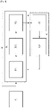
- FIG. 1 partially represents a machine 1 for the cyclic production of containers 2 by stretch-blow molding from preforms 3 made of plastic material.
- the preforms 3 are for example made of polyethylene terephthalate (PET).
- Each preform 3 comprises a neck 4 and a cylindrical body 5 terminated by a hemispherical bottom 6.
- the machine 1 comprises at least one stretch-blow molding station 7 , a single station 7 being represented on the figure 1 .
- Each station 7 is typically mounted on a frame, for example on the periphery of a carousel.
- Station 7 comprises a mold 8 having a cavity 9 intended to receive a preform 3, and having the shape of the container to be produced.
- the station 7 preferably comprises a drawing rod 10 mounted to slide relative to the mold 8 along a main axis X (generally of revolution).
- Station 7 includes a device (not shown) for controlling the axial displacement of rod 10, preferably of the electromagnetic type.
- the station 7 comprises a nozzle 12 covering an upper face of the mold 8, capable of covering the neck 4 of the preform 3 which protrudes therefrom.
- the station 7 comprises a pressure sensor 13 , typically mounted on the nozzle 12 capable of measuring the pressure prevailing inside the preform 3.
- the machine 1 also comprises a pre-blowing circuit 14 comprising a source 15 of pre-blowing fluid.
- the pre-blowing fluid is for example a gas, preferably air.
- the pre-blowing fluid is brought to a pre-blowing pressure, typically between 5 and 16 bars.
- the pre-blowing circuit 14 comprises a conduit 16 connecting the fluid source 15 to the nozzle 12.
- a pre-blowing solenoid valve 17 is interposed between the fluid source 15 and the nozzle 12.
- a controllable device 18 capable of varying the flow rate Dp of pressurized fluid is preferably mounted on the pre-blowing solenoid valve 17, or the pre-blowing solenoid valve 17 has a controllable variable flow rate.
- the pre-blowing solenoid valve 17 is capable of placing the interior of the preform 3, received in the cavity 9, in communication with said source 15 of fluid according to a predetermined pre-blowing flow rate Dp .
- the pre-blowing flow is typically measured using a flow meter.
- pre-blowing phase is meant a phase during at least part of which the stretching rod 10 stretches the preform 3, and during which the preform 3 is fluidically connected by the pre-blowing solenoid valve 17 to the source 15 of pre-blowing fluid.
- the machine 1 further comprises a blowing circuit 19 comprising a source 20 of blowing fluid.
- the blowing fluid is for example a gas, preferably air.
- the blowing fluid is brought to a blowing pressure, typically between 16 and 40 bars.
- the blowing circuit 19 comprises a conduit 21 connecting the source 20 of blowing fluid to the nozzle 12.
- a blowing solenoid valve 22 is interposed between the source 20 of blowing fluid and the nozzle 12.
- a controllable device 23 capable of varying the flow rate Ds of pressurized fluid is preferably mounted on the blow-off solenoid valve 22, or the blow-off solenoid valve 22 has a controllable variable flow rate.
- the machine 1 further comprises a device for controlling the opening and closing of the pre-blowing solenoid valve 17.
- the machine 1 further comprises a device for controlling the opening and closing of the solenoid valve 22 for blowing.
- the machine 1 further comprises an electronic control unit 24 , in particular in the form of a programmable logic controller (PLC), electrically connected to the pressure sensor 13, to the solenoid valves 17, 22 via their controllable devices 18, 23 to regulate the respective flow rates, and if necessary to the device for controlling the movement of the rod 10.
- PLC programmable logic controller
- the machine 1 further comprises a device for monitoring a possible change imposed by the operator of an operating parameter of the machine 1, a device for analyzing a succession of temporal pressure curves prevailing inside of the preform 3 during a stabilization phase without regulation, and a device for updating at least one regulation reference, connected to the analysis device.
- the device for monitoring a possible imposed change typically comprises the processor 25.
- the device for analyzing a succession of pressure time curves prevailing inside the preform during a stabilization phase without regulation typically comprises the processor 25, the analog input module 26 connected to the sensor 13 of pressure to collect the measurements and convert them into a digital signal for processing by the processor 25, and the memory 27 connected to the processor 25 for storing data from the pressure sensor 13 after conversion.
- the device for updating at least one regulation reference typically comprises the processor 25 and the analog output module 28 controlled by the processor 25.
- the updating device is capable of updating at least one regulation reference according to the analysis of the succession of pressure time curves during the stabilization phase without regulation.
- the monitoring device, the analyzing device and the updating device make it possible to continue the regulation of the cyclic production of containers even after the change of an operating parameter of the machine 1.
- the machine 1 also comprises a device for detecting a moment, called the real moment of the start of pre-blowing Ar, when the pressure in the preform 3 begins to increase.
- the pre-blowing start time is a characteristic point A of a pre-blowing curve corresponding to the pressure prevailing inside the preform 3 during at least part of the pre-blowing.
- the device for detecting the real time Ar of the start of pre-blowing typically comprises the processor 25, capable of detecting the real time Ar from the data collected by the pressure sensor 13, converted by the analog input module 26 and memorized by memory 27
- the machine 1 typically also comprises a device for comparing the real time Ar of the start of pre-blowing with a reference time Ac of the start of pre-blowing, and a device for regulating a control time of opening TRo of the pre-blowing solenoid valve 17 as a function of the result of this comparison.
- the reference time Ac is determined and adjusted by an operator according to a process for producing a container according to the characteristics desired for the final container.
- the actual pre-blowing start time Ar may differ from the pre-blowing start reference time Ac when the opening of the pre-blowing solenoid valve 17 occurs too soon, in which case the real pre-blowing start time Ar is anticipated by relative to the pre-blowing start reference instant Ac, or too late in which case the real pre-blowing start instant Ar is delayed relative to the pre-blowing start reference instant Ac.
- the device for comparing the real time Ar of the start of pre-blowing with a reference time Ac of the start of pre-blowing typically comprises the processor 25, capable of comparing the data of said real time Ar with the data of said reference time Ac recorded by the memory 27.
- the device for regulating the opening control time TRo of the pre-blowing solenoid valve 17 according to the result of this comparison typically comprises the processor 25, capable of controlling the analog output module 28 controlling the pre-blowing solenoid valve 17 via the device for controlling the opening and closing of the pre-blowing solenoid valve 17.
- the machine 1 further comprises a device for detecting a real instant of pressure peak Br where the pressure in the preform 3 reaches a peak.
- the pressure peak instant is a characteristic point B of the pre-blowing curve.
- the device for detecting the real time Br of the pressure peak typically comprises the processor 25, capable of detecting the real time Br from the data collected by the pressure sensor 13, converted by the analog input module 26 and stored by the memory 27
- the machine 1 typically also comprises a device for comparing the real time Br of the pressure peak with a reference time Bc of the pressure peak, and a device for regulating the flow rate Dp injected into the preform 3 depending on the result of this comparison.
- the reference time Bc is determined and adjusted by an operator according to a process for producing a container according to the characteristics desired for the final container.
- the actual pressure peak instant Br may differ from the reference instant Bc of the pressure peak when the pre-blowing fluid flow rate Dp is too high, in which case the actual pressure peak instant Br is anticipated with respect to the reference instant Bc of pressure peak, or too low in which case the real instant Br of pressure peak is delayed with respect to the reference instant Bc of pressure peak.
- the device for comparing the real instant Br of pressure peak with a reference instant Bc of pressure peak typically comprises the processor 25, capable of comparing the data of said real instant Br with the data of said reference instant Bc recorded by the memory 27.
- the device for regulating the pre-blowing flow Dp injected into the preform 3 according to the result of this comparison typically comprises the processor 25, capable of controlling the analog output module 28 controlling the pre-blowing solenoid valve 17 via the controllable device 18 capable of varying the flow rate of pressurized fluid injected into the preform 3, so as to modulate the pre-blowing flow rate Dp.
- the machine 1 further comprises a device for calculating a real slope PRab of increase in pressure between the pressure measured at the real time Br of the pressure peak and the pressure measured at the real time Ar of start of pre-blowing.
- the value of the real slope PRab thus depends on the real time Ar of the start of preblowing, the real time Br of the pressure peak and the pressure values measured at these times.
- the device for calculating the real slope PRab typically comprises the processor 25, capable of calculating the real slope between the characteristic points A of the start of pre-blowing and B of pressure peak measured by the pressure sensor 13, converted by the analog input module 26 and stored by the memory 27.
- the slope between the pressure measured at the pressure peak instant and the pressure measured at the pre-blowing start instant is a characteristic point Pab of the pre-blowing curve. Since the pressure time curve between the start of pre-blowing and the pressure peak is not straight, the calculation of the actual slope PRab is calculated in a predetermined manner taken from among the many options available to those skilled in the art, such as 'an average of the derivatives, or an average of the increases in pressure by identical time increments, etc...
- the machine 1 typically further comprises a device for comparing the actual slope PRab with a reference slope PCab of pressure increase, and a device for regulating the flow rate Dp injected into the preform 3 depending of the result of this comparison.
- the device for comparing the real slope PRab with a reference slope PCab typically comprises the processor 25, able to compare the data of said real slope PRab with the data of said reference slope PCab recorded by the memory 27.
- the device for regulating the flow rate Dp injected into the preform 3 as a function of the result of this comparison typically comprises the processor 25, capable of controlling the analog output module 28 controlling the pre-blowing solenoid valve 17 via the controllable device 18 capable of varying the pressurized fluid flow injected into the preform 3, so as to modulate the pre-blowing flow Dp.
- the machine 1 also comprises a device for detecting a moment, called the real moment of the end of pre-blowing, when the pressure in the preform 3 starts to increase again after the pressure dip.
- a moment called the real moment of the end of pre-blowing
- This increase is due to the fact that, after a time delay, during which the pre-blowing solenoid valve 17 is kept open, blowing is started by simultaneously controlling the closing of the pre-blowing solenoid valve 17 and the opening of the blowing, which causes a sudden increase in pressure in the preform 3.
- the device for detecting the real time of the end of pre-blowing typically comprises the processor 25, capable of detecting the real time of the end of pre-blowing from the data collected by the pressure sensor 13, converted by the analog input module 26 and stored by the memory 27.
- the pre-blowing end time is a characteristic point F of the pre-blowing curve.
- the machine 1 typically further comprises a device for comparing a real pressure Fr at the end of pre-blowing corresponding to the pressure measured at the real time of the end of pre-blowing detected, with a reference pressure Fc of end of pre-blowing, and a device for regulating the flow Dp injected into the preform 3 according to the result of this comparison.
- the reference pressure Fc is determined and adjusted by an operator according to a method of producing a container according to the characteristics desired for the final container.
- the real time Fr of the end of pre-blowing may differ from the reference time Fc of the end of pre-blowing when the flow rate Dp of pre-blowing fluid is too high, in which case the real pressure Fr of the end of pre-blowing is greater than the reference pressure Fc at the end of pre-blowing, or too low in which case the actual pressure Fr at the end of pre-blowing is lower than the reference pressure Fc at the end of pre-blowing.
- the real time comparison device typically comprises the processor 25, capable of comparing the data of said real pressure Fr with the data of said reference pressure Fc stored by the memory 27.
- the device for regulating the pre-blowing flow rate Dp injected into the preform 3 as a function of the result of this comparison typically comprises the processor 25, capable of controlling the module 28 controlling the pre-blowing solenoid valve 17 which can be adjustable or associated with a flow rate adjustable via the controllable device 18 capable of varying the flow rate of pressurized fluid injected into the preform 3, so as to modulate the pre-blowing flow rate Dp.
- the characteristic points A, B, Pab and F are chosen to regulate the machine 1 by ensuring good synchronization of the bidirectional stretching and good distribution of the material during the pre-blowing.
- the method comprises an initialization phase a) including a step of setting up by an operator and of storing a plurality of operating parameters of the machine 1 during the production cycle, and regulation parameters including at least one reference position Ac, Bc, PCab and Fc of at least one characteristic point A, B, Pab and F of the pre-blowing curve, said reference position Ac, Bc, PCab and Fc being determined by a reference instant and/ or a reference pressure.
- the reference position is determined by a reference time Ac, Bc, the reference position corresponds to a time at which the pressure prevailing inside the preform 3 is measured at said characteristic point A, B, said characteristic point then being characterized by a particular moment.
- the reference position When the reference position is determined by a reference pressure Fc, the reference position corresponds to the pressure measured at the instant of said characteristic point F, said characteristic point F then being characterized by a particular pressure value.
- the operating parameters of the machine 1 are typically taken from among: the instant of opening control TRo of the pre-blowing solenoid valve 17, a value or a temporal profile of the pre-blowing flow rate Dp, the pre-blowing pressure or a temporal profile of a stroke of the rod 10 for stretching.
- the opening command time TRo differs from the pre-blowing start reference time Ac because there is a response time between the time when the opening of the pre-blowing solenoid valve is commanded and the time when the pre-blowing actually begins inside the preform 3.
- the storage of a plurality of operating parameters of the machine 1 during the production cycle, and regulation parameters is typically operated by the memory 27.
- Each pressure measurement is performed by the pressure sensor 13 of the station 7 concerned.
- each measurement is an average of five measurements taken over five cycles.
- the reference instant Ac of the start of preblowing is typically determined by the instant when the measured pressure prevailing inside a preform 3 begins to increase.
- the pre-blowing start reference instant Ac is typically set up by an operator using the communication interface 29 in the control unit 24, stored by the memory 27, processed by the processor 25, which control by the analog output module 28 the device for controlling the opening of the pre-blowing solenoid valve 17.
- the pressure peak reference time Bc is typically set up by an operator using the communication interface 29 in the control unit 24, stored by the memory 27, processed by the processor 25, which the analog output module 28 controls the pre-blowing solenoid valve 17 via the controllable device 18 capable of varying the pre-blowing flow rate Dp.
- the pre-blowing pressure peak reference instant Bc is reached a few milliseconds after the opening of the pre-blowing solenoid valve 17.
- the reference slope PCab is typically set up by an operator using the communication interface 29 in the control unit 24, stored by the memory 27, processed by the processor 25, which controls by the module 28 analog output pre-blowing solenoid valve 17 via the controllable device 18 capable of varying the pre-blowing flow rate Dp, and/or the pressure value of the pre-blowing fluid source 15, and/or the value of the nominal speed or of the stretching temporal profile of the draw rod 10 via the axial displacement control device of the rod 10.
- the end of preblowing reference pressure Fc typically corresponds to the pressure at the end of preblowing reference instant when the pressure in the preform 3 begins to increase again.
- pre-blowing reference pressure Fc is typically set up by an operator using the communication interface 29 in the control unit 24, stored by the memory 27, processed by the processor 25, which controls via the analog output module 28 the pre-blowing solenoid valve 17 via the controllable device 18 capable of varying the pre-blowing flow rate Dp.
- pre-blowing reference pressure Fc The end of pre-blowing reference pressure Fc is generally a few bars.
- the method further comprises a phase b) of regulated production comprising a step b1) and a step b2).
- At least one preform 3 is stretched and blown by injecting a pressurized fluid, typically from the source 15 of preblowing fluid then from the source 20 of blowing fluid in each station 7.
- pre-blowing fluid is typically triggered by the opening of the pre-blowing solenoid valve 17.
- the pre-blowing fluid is injected at a nominal pre-blowing flow rate then according to a determined pre-blowing flow rate time profile Dp.
- the stretching rod 10 is put into operation at a nominal speed then according to a determined stretching time profile.
- nominal speed of the drawing rod it is understood between 1 m/s and 2.5 m/s.
- the pre-blowing solenoid valve 17 is closed, and the injection of blowing fluid is typically triggered by the opening of the blowing solenoid valve 22 .
- step b1) for at least one station 7 of machine 1, called the reference station, the pre-blowing curve including the characteristic point A, B, Pab, F is calculated from the pressure measurements typically recorded by the pressure sensor 13 and recorded in the memory 27, then the curve is stored, and a real instant and/or a real pressure Ar, Br, PRab and Fr is calculated or determined, corresponding to said characteristic point A, B, Pab, F for the measured pre-blowing curve.
- the real pre-blowing start time Ar is detected by the device for detecting the real pre-blowing start time Ar.
- the real time Br of the pre-blowing pressure peak is detected by the device for detecting the real time Br of the pre-blowing pressure peak.
- the real slope PRab is calculated by the device for calculating the real slope PRab between the pressure measured at the real time Br of the pressure peak and the pressure measured at the real time of the start of pre-blowing.
- the real time Fr of the end of pre-blowing is detected by the device for detecting the real time Fr of the end of pre-blowing.
- the total pre-blowing duration for a preform 3 is typically between 50 ms and 300 ms.
- step b2) a new value of at least one operating parameter of machine 1 is calculated and stored as a function of a difference between the real time and the reference time and/or between the real pressure and the reference pressure corresponding to the characteristic point A, B, Pab, F.
- the new value of the operating parameter is calculated by the processor 25 and stored by the memory 27.
- the regulation parameters further include the storage of at least one acceptance tolerance of the real position Ar, Br, PRab, Fr of the at least one characteristic point A, B, Pab, F of the curve pre-blowing selected with respect to the position of reference Ac, Bc, PCab, Fc of said characteristic point A, B, Pab, F, and there is no calculation of a new value of said operating parameter of machine 1 if said deviation is less than the tolerance of acceptance.
- the acceptance tolerance is an acceptance tolerance in time for the characteristic points of the start A of pre-blowing and B of the pre-blowing pressure peak, and an acceptance tolerance in pressure for the characteristic point F of the end of pre-blowing.
- the acceptance tolerance for the characteristic point Pab is a slope tolerance.
- the acceptance tolerance for characteristic point A is between 1 and 3 ms.
- the acceptance tolerance for characteristic point B is between 1 and 3 ms.
- the acceptance tolerance for the characteristic point Pab is between 15 mbar/ms and 60 mbar/ms.
- the acceptance tolerance for the characteristic point F is between 0.1 bar and 0.3 bar.
- the curve comprising the indicated characteristic points A, B, F with acceptance tolerances illustrated by rectangles, illustrates the regulation parameters stored during an initialization phase of the method.
- the other curve in each figure illustrates the actual pressure measured in the preform during pre-blowing.
- the upper figure illustrates the curves during step “b1” of the regulation phase.
- the lower figure illustrates the effect of step “b2” of the regulation phase, concerning the characteristic point concerned by each figure.
- the real time Ar of the start of pre-blowing is compared with the reference time Ac of the start of pre-blowing, using the device for comparing the real time Ar of the start of pre-blowing with the reference time Ac of start of pre-blowing.
- step b1 If the real time Ar of the start of pre-blowing in the preform 3 of the reference station measured in step b1) is later, respectively earlier (as in the example of figure 4 ), a time difference at the reference instant Ac of the start of pre-blowing for said reference station greater than the acceptance tolerance, the new value calculated in step b2) as opening control instant TRo of the pre-blowing solenoid valve 17 of each of the stretch-blowing stations 7 is then anticipated, respectively delayed (as in the example of the figure 4 ), said time difference in all the stretch-blow molding stations 7, for example using the device for regulating the opening control time TRo of the solenoid valve 17 for pre-blowing.
- the regulation parameters stored during the initialization phase comprise the instant Ac of the start of pre-blowing and, advantageously, an acceptance tolerance for this instant.
- the characteristic point on the measured pressure curve is the instant Ar of the start of pre-blowing.
- the operating parameter of machine 1 likely to have an influence on the start of pre-blowing is the instant TRo of the solenoid valve opening command.
- Step “b2” of the regulation phase includes calculating, from the measured curve, the pre-blowing start time Ar and calculating a difference with the pre-blowing start setpoint time Ac. It can advantageously comprise comparing the calculated difference with the regulation limit.
- the possible limit includes calculating a new time TRo for controlling the pre-blowing solenoid valve 17 according to the calculated difference and possibly part or all of the acceptance tolerance. concerning the time of the start of pre-blowing. This new machine 1 parameter value will be taken into account during the next container production cycle or cycles.
- the regulation parameters stored during the initialization phase comprise the average slope PCab between the instant Ac of the start of pre-blowing and the peak B of pre-blowing pressure, as well as a possible acceptance tolerance for this slope. They can advantageously include, but not necessarily, the regulation parameters of the embodiment illustrated in figure 4 .
- Step “b1" of the regulation phase for the embodiment figure 5 includes the calculation of the average slope PRab between the start of pre-blowing and the pre-blowing pressure peak from the measured pressure curve, as well as a difference between this actual slope PRab and the setpoint slope PCab. It can advantageously comprise comparing the calculated difference with the possible limit of regulation of the slope PCab.
- This step “b1" of the regulation phase can also advantageously, but not necessarily, comprise the calculations performed during step "b1" of the embodiment of the figure 4 .
- the machine parameters likely to have an influence on the average slope are taken from: the nominal flow rate or the temporal profile of the flow rate of the pre-blowing fluid, the nominal speed or the temporal profile of the drawing speed by the rod 10, the nominal pressure or the time profile of the pre-blowing pressure, or a combination of one or more of the aforementioned parameters.
- Step “b2" of the illustrated embodiment figure 5 comprises the calculation of a new value of one or more of the parameters of the machine 1 likely to have an influence on the slope PRab, as a function of the calculated deviation and possibly of part or all of the tolerance d acceptance concerning the slope PRab.
- This step “b2” of the regulation phase can also advantageously, but not necessarily, comprise the calculation of the parameter of the machine 1 carried out for the embodiment of the figure 4 .
- the new value of one or more of said machine parameters is applied as a setpoint during the or one of the following container production cycles.
- the regulation phase also includes the actions of the regulation phase of the illustrated embodiment figure 4
- the application of the new machine parameter setpoints can be done during the same subsequent production cycle or during different subsequent production cycles.
- the regulation parameters stored during the initialization phase include the pressure at the end of pre-blowing, as well as a possible acceptance tolerance for this pressure. They can advantageously include, but not necessarily, the regulation parameters of the embodiment illustrated in figure 4 and/or in figure 5 .
- Step “b1" of the regulation phase for the embodiment figure 6 includes the calculation from the measured pressure curve of the pressure at the end of pre-blowing, as well as a difference between this pressure Fr and the setpoint pressure Fc. It can advantageously include comparing the calculated deviation with the possible pressure regulation limit Fc.
- This step “b1" of the regulation phase can also advantageously, but not necessarily, comprise the calculations performed during step “b1" of the embodiment of the figure 4 and or figure 5 .
- the machine parameters likely to have an influence on the end of pre-blowing pressure are chosen from among: the time profile of the flow rate of the pre-blowing fluid, the nominal pressure or the time profile of the pre-blowing pressure, or a combination of one or several of the above parameters.
- Step “b2" of the illustrated embodiment figure 6 comprises the calculation of a new value of one or more of the parameters of the machine 1 likely to have an influence on the pressure Fr at the end of pre-blowing, as a function of the calculated difference and possibly of part or all of the acceptance tolerance concerning the pressure Fr.
- This step “b2" of the regulation phase can also advantageously, but not necessarily, comprise the calculation of the parameter of the machine 1 carried out for the embodiment of the figure 4 and or figure 5 .
- the new value of one or more of said machine parameters is applied as a setpoint during the or one of the following container production cycles.
- the regulation phase also includes the actions of the regulation phase of the illustrated embodiment figure 4
- the application of the new machine parameter setpoints can be done during the same subsequent production cycle or during different subsequent production cycles.
- the regulated production phase b) of the method according to the invention further includes a monitoring step b3) of a possible change imposed by the operator of a value of an operating parameter of the machine 1.
- the monitoring step b3) is implemented by the device for monitoring a possible change imposed by the operator of an operating parameter of the machine 1.
- An operator can impose the change of one or more parameters operation of machine 1, for example when preforms 3 have different characteristics in terms of composition, or heating temperature before pre-blowing are used, or to modify the production process according to the characteristics of the desired final container.
- the regulation method further comprises a phase of automatic updating of the regulation parameter(s) which is implemented in the event of an imposed change in an operating parameter of the machine 1.
- the update phase includes c1) a stabilization step during which production is continued from the operating parameter of machine 1 imposed for a predetermined stabilization time, and for each production cycle actions b1) are executed, and actions b2) are suspended.
- step c1) the pressure time curves are for example stored, and analyzed by the device for analyzing a succession of pressure time curves prevailing inside the preform 3 during the stabilization phase without regulation.
- the duration of the stabilization stage is determined by reaching a production cycle during which a real instant or a real pressure measured at a characteristic point A, B, Pab, F is less than to the acceptance tolerance for that actual time or pressure.
- the stabilization step has for example a duration of between 1 and 3 minutes. It is noted that during this time, the production continues, it is only the regulation system which is in the automatic update phase, but the criteria of quality and acceptance of the container produced continue to be active.
- c2) a step of correcting the reference time and/or the reference pressure as a function of the real time and/or real pressure values stored during the stabilization step c1), in order to continue the phase b) of regulated production.
- Step c2) is for example implemented by the device for updating at least one regulation reference, connected to the analysis device.
- phase b) of regulated production firstly comprises a possible imposed change in the opening command time TRo of the pre-blowing solenoid valve 17, then after the monitoring step b3), the step of stabilization c1) is triggered until a production cycle during which the real instant Ar of the start of pre-blowing in the preform 3 is stabilized by exhibiting a lesser variation than the acceptance tolerance of the start of pre-blowing.
- the real pre-blowing start time Ar is taken as the new pre-blowing start reference time Ac.
- the real time Br of pressure peak is calculated for the following production cycles, and compared with the reference time Bc of pressure peak, for example using the device for comparing the real time Br of peak of pressure with the reference moment Bc of pressure peak.
- a new pre-blowing flow rate value is calculated Dp reduced, respectively increased with respect to the value of the pre-blowing flow Dp during the production cycle during which the real time Br of the pressure peak was calculated, for example using the pre-blowing flow regulating device Dp injected into the preform 3, as shown in the figure 5 .
- the new pre-blowing flow rate value Dp is for example applied using the controllable device 18 capable of varying the flow rate of pressurized fluid, or the controllable variable flow solenoid valve.
- the regulated production phase b) firstly comprises the possible imposed change of the instant of opening control TRo of the pre-blowing solenoid valve 17, then after the monitoring step b3), the step of stabilization c1) is triggered up to a production cycle during which the real instant Ar of the start of preblowing in the preform 3 is lower than the acceptance tolerance of the start of preblowing, then phase b) comprises the possible imposed change in the pre-blowing flow rate Dp, then, after the monitoring step b3), the stabilization step c1) is triggered until a production cycle during which the real time Ar of the start of the pre-blowing and the real moment Br of pressure peak are lower than their respective acceptance tolerance.
- the real slope PRab between the real time Ar of the start of pre-blowing and the real time Br of the pressure peak is calculated for the following production cycles.
- the real slope PRab is for example compared with the reference pressure PCab using the device for comparing the real slope PRab with the reference pressure PCab.
- the new nominal pre-blowing flow rate value or the new pre-blowing flow rate temporal profile Dp are for example calculated by the device for regulating the flow rate injected into the preform as a function of the result of this comparison.
- the new pressure value of the pressurized fluid source 15 is for example calculated by the device for regulating the pressure of the pressurized fluid source 15 as a function of the result of this comparison.
- the new value of nominal speed or stretching time profile of the stretching rod 10 is for example calculated by the device for regulating the nominal speed or stretching time profile of the stretching rod 10 according to the result of this comparison.
- the device for regulating the pre-blowing flow rate Dp injected into the preform 3 will control a modification of the pre-blowing flow rate Dp.
- the machine 1 is equipped with at least a first station 7 and a second station, one of the stations is a reference station.
- Each station 7 is provided with a pressure sensor 13 prevailing inside the preform 3 of said station 7 and with a pre-blowing solenoid valve 17 having a real response time between the moment of command of the opening TRo of the pre-blowing solenoid valve 17 and the actual start of the pressure increase in the preform 3.
- FIG 7 represents a plurality of pre-blowing curves obtained during pre-blowing cycles without regulation
- the figure 8 represents a plurality of pre-blowing curves obtained during pre-blowing cycles with regulation according to the method of the invention. It clearly appears that the pre-blowing curves are much closer to each other with regulation, thus demonstrating the obtaining of more regular pre-blowing curves, and consequently less variability of the final containers.
- the regulation method according to the invention makes it possible to continue the regulated production in the event of an imposed change in an operating parameter of the machine 1 in introducing new regulation references, without the regulation being stopped and it being necessary to manually set up new references.
- the present invention also relates to a computer program product intended to be implemented on the machine 1.
Landscapes
- Engineering & Computer Science (AREA)
- Manufacturing & Machinery (AREA)
- Mechanical Engineering (AREA)
- Health & Medical Sciences (AREA)
- Artificial Intelligence (AREA)
- Computer Vision & Pattern Recognition (AREA)
- Evolutionary Computation (AREA)
- Medical Informatics (AREA)
- Software Systems (AREA)
- Physics & Mathematics (AREA)
- General Physics & Mathematics (AREA)
- Automation & Control Theory (AREA)
- Blow-Moulding Or Thermoforming Of Plastics Or The Like (AREA)
- Organic Low-Molecular-Weight Compounds And Preparation Thereof (AREA)
Abstract
Procédé de régulation d'une production cyclique de récipients (2) par étirage-soufflage à partir de préformes (3), comprenant :a) une phase d'initialisation d'une pluralité de paramètres de fonctionnement de la machine (1) pendant le cycle de production, et de paramètres de régulation incluant au moins une position de référence (Ac, Bc, PCab, Fc) d'au moins un point caractéristique (A, B, Pab, F) d'une courbe de présoufflage,b) une phase de production régulée au cours de laquelle :b1) la courbe de présoufflage est mesurée et mémorisée, et un instant réel et/ou une pression réelle est calculé(e) correspondant audit point caractéristique (A, B, Pab, F), etb2) une nouvelle valeur d'au moins un paramètre de fonctionnement de la machine (1) est calculée en fonction d'un écart entre l'instant réel et l'instant de référence et/ou entre la pression réelle et la pression de référence,caractérisé en ce que la phase de production régulée inclut une étape de surveillance b3) d'un éventuel changement imposé par l'opérateur d'une valeur d'un paramètre de fonctionnement de la machine (1),et comprenant en outre une phase de mise à jour automatique des paramètres de régulation incluant :c1) une étape de stabilisation au cours de laquelle la production est poursuivie et les actions b1) sont exécutées, et les actions b2) sont suspendues, etc2) une étape de correction de l'instant de référence et/ou de la pression de référence en fonction des valeurs d'instant réel et/ou de pression réelle mémorisées au cours de l'étape de stabilisation, afin de poursuivre la phase de production régulée.Method for regulating a cyclic production of containers (2) by stretch-blow molding from preforms (3), comprising:a) an initialization phase of a plurality of operating parameters of the machine (1) during the production cycle, and regulation parameters including at least one reference position (Ac, Bc, PCab, Fc) of at least one characteristic point (A, B, Pab, F) of a pre-blowing curve, b) a regulated production phase during which: b1) the pre-blowing curve is measured and stored, and a real instant and/or a real pressure is calculated corresponding to said characteristic point (A, B, Pab, F), andb2) a new value of at least one operating parameter of the machine (1) is calculated as a function of a difference between the actual instant and the reference instant and/or between the actual pressure and the reference pressure ,characterized in that the regulated production phase includes a monitoring step b3) of a possible change imposed by the operator of a value of an operating parameter of the machine (1),and further comprising a phase automatic updating of the regulation parameters including: c1) a stabilization step during which production is continued and the actions b1) are executed, and the actions b2) are suspended, etc2) a step for correcting the reference time and/or the reference pressure as a function of the real time and/or real pressure values stored during the stabilization step, in order to continue the regulated production phase.
Description
La présente invention concerne un procédé de régulation d'une production cyclique de récipients par étirage-soufflage à partir de préformes en matière plastique dans une machine comprenant une ou plusieurs stations d'étirage-soufflage conçues chacune pour produire un récipient au cours d'un cycle de production, et pourvues chacune d'une électrovanne de présoufflage raccordant fluidiquement la préforme à une source de fluide sous pression pendant une phase de présoufflage.The present invention relates to a method for regulating a cyclical production of containers by stretch blow molding from plastic preforms in a machine comprising one or more stretch blow molding stations each designed to produce a container during a production cycle, and each provided with a pre-blowing solenoid valve fluidically connecting the preform to a source of pressurized fluid during a pre-blowing phase.
La production cyclique de récipients par étirage-soufflage comporte typiquement le chauffage d'une préforme en matière plastique jusqu'à la température de transition vitreuse de la préforme, puis l'introduction de la préforme chauffée dans un moule, l'injection de fluide sous pression dans la préforme pour former un récipient dans le moule, et le retrait du récipient du moule.Cyclic production of containers by stretch blow molding typically involves heating a plastic preform to the glass transition temperature of the preform, then introducing the heated preform into a mold, injecting fluid under pressing the preform to form a container in the mould, and removing the container from the mould.
L'injection de fluide sous pression comprend elle-même plusieurs étapes successives. Une première étape, dite de présoufflage consiste à injecter un fluide sous pression réduite, dite de présoufflage et généralement comprise entre 5 et 16 bars, dans la préforme de façon à former une bulle pendant qu'une tige d'étirage étire la préforme. La tige d'étirage entraîne un étirage mécanique selon une direction longitudinale de la préforme tandis que l'injection de fluide sous pression entraîne un étirage selon une direction transversale, perpendiculaire à la direction longitudinale. L'étirage est ainsi bidirectionnel, afin de garantir une répartition homogène de la matière ainsi qu'une bonne orientation des chaînes moléculaires.The injection of pressurized fluid itself comprises several successive steps. A first step, called pre-blowing, consists of injecting a fluid under reduced pressure, called pre-blowing and generally between 5 and 16 bars, into the preform so as to form a bubble while a stretching rod stretches the preform. The stretching rod causes mechanical stretching in a longitudinal direction of the preform while the injection of pressurized fluid causes stretching in a transverse direction perpendicular to the longitudinal direction. The stretching is thus bidirectional, in order to guarantee a homogeneous distribution of the material as well as a good orientation of the molecular chains.
Une seconde opération, dite de soufflage, consiste à injecter un fluide sous haute pression, généralement supérieure à 25 bars, et couramment comprise entre 30 et 35 bars. L'opération de soufflage permet de plaquer la bulle formée par la préforme en matière plastique contre les parois du moule, et ainsi de former un récipient présentant une forme souhaitée et bien définie.A second operation, called blowing, consists in injecting a fluid under high pressure, generally greater than 25 bars, and commonly between 30 and 35 bars. The blowing operation makes it possible to press the bubble formed by the plastic preform against the walls of the mold, and thus to form a container having a desired and well-defined shape.
La phase de présoufflage est primordiale dans le développement du plastique de la préforme, et dans l'orientation des chaînes moléculaires. Un défaut de présoufflage entraîne une mauvaise répartition de la matière, et ainsi aboutit à des récipients défectueux car fragilisés. Dans un contexte de production industrielle à cadence élevée, le présoufflage doit être maîtrisé afin de garantir la qualité des récipients formés à partir de préformes en matière plastique. Il est connu de
On connait également le document
Il arrive qu'un opérateur impose le changement d'un ou de plusieurs paramètres de fonctionnement de la machine, par exemple lorsque de nouvelles préformes sont utilisées présentant des caractéristiques différentes en termes de composition, ou de température de chauffe avant présoufflage.It happens that an operator imposes the change of one or more operating parameters of the machine, for example when new preforms are used having different characteristics in terms of composition, or heating temperature before pre-blowing.
Cependant, la modification d'un paramètre de fonctionnement de la machine en cours de production entraîne un arrêt de la régulation et la production cyclique de récipients continue sans régulation. Il est alors nécessaire de reprendre des points de référence manuellement pour que la régulation puisse reprendre.However, the modification of an operating parameter of the machine during production leads to a stoppage of the regulation and the cyclic production of containers continues without regulation. It is then necessary to resume the reference points manually so that the regulation can resume.
Il en résulte une dérive de la phase de présoufflage, ainsi qu'une diminution de productivité.This results in a drift of the pre-blowing phase, as well as a decrease in productivity.
Il existe donc un besoin d'améliorer le fonctionnement de la machine lorsqu'un opérateur perturbe le système de régulation.There is therefore a need to improve the operation of the machine when an operator disturbs the regulation system.
A cet effet, la présente invention a pour objet un procédé de régulation d'une production cyclique de récipients par étirage-soufflage à partir de préformes en matière plastique dans une machine comprenant une ou plusieurs stations d'étirage-soufflage conçues chacune pour produire un récipient au cours d'un cycle de production, et pourvues chacune d'une électrovanne de présoufflage raccordant fluidiquement la préforme à une source de fluide sous pression fournissant un débit de présoufflage pendant une phase de présoufflage, le procédé de régulation comprenant :
- a) une phase d'initialisation incluant une étape de mise en place par un opérateur et de mémorisation d'une pluralité de paramètres de fonctionnement de la machine (1) pendant le cycle de production, et de paramètres de régulation incluant au moins une position de référence (Ac, Bc, PCab, Fc) d'au moins un point caractéristique (A, B, Pab, F) d'une courbe de présoufflage correspondant à la pression régnant à l'intérieur de la préforme durant au moins une partie du présoufflage, ladite position de référence (Ac, Bc, PCab, Fc) étant déterminée par un instant de référence et/ou une pression de référence,
- b) une phase de production régulée au cours de laquelle, pour chaque cycle de production, au moins une préforme est étirée et soufflée par injection d'un fluide sous pression dans chaque station et au cours de laquelle :
- b1) pour au moins une station de référence de la machine, la courbe de présoufflage incluant le point caractéristique est mesurée et mémorisée, et un instant réel et/ou une pression réelle est calculé(e) ou déterminé(e), correspondant audit point caractéristique (A, B, Pab, F) pour la courbe de présoufflage mesurée, et
- b2) une nouvelle valeur d'au moins un paramètre de fonctionnement de la machine est calculée et mémorisée en fonction d'un écart entre l'instant réel et l'instant de référence et/ou entre la pression réelle et la pression de référence,
- le procédé de régulation étant caractérisé en ce que la phase de production régulée inclut une étape de surveillance b3) d'un éventuel changement imposé par l'opérateur d'une valeur d'un paramètre de fonctionnement de la machine,
- le procédé de régulation comprenant en outre une phase de mise à jour automatique du ou des paramètres de régulation qui est mise en œuvre en cas de changement imposé d'un paramètre de fonctionnement de la machine, incluant :
- c1) une étape de stabilisation au cours de laquelle la production est poursuivie à partir du paramètre imposé pendant une durée de stabilisation prédéterminée, et pour chaque cycle de production les actions b1) sont exécutées, et les actions b2) sont suspendues, et
- c2) une étape de correction de l'instant de référence et/ou de la pression de référence en fonction des valeurs d'instant réel et/ou de pression réelle mémorisées au cours de l'étape de stabilisation, afin de poursuivre la phase de production régulée.
- a) an initialization phase including a step of setting up by an operator and storage of a plurality of operating parameters of the machine (1) during the production cycle, and regulation parameters including at least one reference position (Ac, Bc, PCab, Fc) of at least one characteristic point ( A, B, Pab, F) of a pre-blowing curve corresponding to the pressure prevailing inside the preform during at least part of the pre-blowing, said reference position (Ac, Bc, PCab, Fc) being determined by a reference instant and/or a reference pressure,
- b) a regulated production phase during which, for each production cycle, at least one preform is stretched and blown by injection of a fluid under pressure in each station and during which:
- b1) for at least one reference station of the machine, the pre-blowing curve including the characteristic point is measured and stored, and a real instant and/or a real pressure is calculated or determined, corresponding to said point characteristic (A, B, Pab, F) for the measured pre-blowing curve, and
- b2) a new value of at least one operating parameter of the machine is calculated and stored according to a difference between the actual instant and the reference instant and/or between the actual pressure and the reference pressure,
- the regulation method being characterized in that the regulated production phase includes a monitoring step b3) of a possible change imposed by the operator of a value of an operating parameter of the machine,
- the regulation method further comprising a phase of automatic updating of the regulation parameter or parameters which is implemented in the event of an imposed change in an operating parameter of the machine, including:
- c1) a stabilization step during which production is continued from the imposed parameter for a predetermined stabilization time, and for each production cycle actions b1) are executed, and actions b2) are suspended, and
- c2) a step of correcting the reference time and/or the reference pressure as a function of the real time and/or real pressure values stored during the stabilization step, in order to continue the phase of regulated production.
Grâce à la phase de mise à jour automatique du ou des paramètres de régulation, le procédé selon l'invention permet de poursuivre la régulation en cas de changement imposé d'un paramètre de fonctionnement de la machine. Il n'est plus nécessaire de reprendre manuellement des points de référence.Thanks to the phase of automatic updating of the regulation parameter or parameters, the method according to the invention makes it possible to continue the regulation in the event of an imposed change in an operating parameter of the machine. It is no longer necessary to manually pick up reference points.
Selon d'autres caractéristiques du procédé prises isolément ou selon toute combinaison techniquement envisageable :
- les paramètres de fonctionnement de la machine susceptibles d'être recalculés pendant l'étape b2) sont pris parmi : un instant de commande d'ouverture (TRo) de l'électrovanne de présoufflage, une valeur ou un profil temporel de débit de présoufflage, une pression de présoufflage ou un profil temporel d'une course d'une tige d'étirage,
- les paramètres de régulation incluent la mémorisation d'au moins une tolérance d'acceptation d'une position réelle (Ar, Br, PRab, Fr) de l'au moins un point caractéristique (A, B, Pab, F) de la courbe de présoufflage choisi par rapport à la position de référence dudit point caractéristique (A, B, Pab, F), et dans lequel il n'y a pas de calcul d'une nouvelle valeur dudit paramètre de fonctionnement de la machine (1) si ledit écart est inférieur à la tolérance d'acceptation.
- the operating parameters of the machine likely to be recalculated during step b2) are taken from: an opening command time (TRo) of the pre-blowing solenoid valve, a pre-blowing flow rate value or time profile, a pre-blowing pressure or a time profile of a stretch rod stroke,
- the regulation parameters include the storage of at least one acceptance tolerance of a real position (Ar, Br, PRab, Fr) of the at least one characteristic point (A, B, Pab, F) of the curve of pre-blowing chosen with respect to the reference position of said characteristic point (A, B, Pab, F), and in which there is no calculation of a new value of said operating parameter of the machine (1) if said deviation is less than the acceptance tolerance.
Ainsi, en cas d'un écart faible entre l'instant réel et l'instant de référence et/ou entre la pression réelle et la pression de référence, la valeur du paramètre de fonctionnement de la machine dont le changement a été imposé est conservée sans impacter de manière trop importante la productivité de la machine.Thus, in the event of a small difference between the real time and the reference time and/or between the real pressure and the reference pressure, the value of the operating parameter of the machine whose change has been imposed is retained. without significantly impacting the productivity of the machine.
Selon d'autres caractéristiques du procédé prises isolément ou selon toute combinaison techniquement envisageable :
- les paramètres de régulation comprennent un instant de référence (Ac) du début d'augmentation de pression dans la préforme, appelé instant de référence (Ac) de début de présoufflage, et une tolérance pour l'instant de référence (Ac) de début de présoufflage,
et, si l'instant réel (Ar) de début de présoufflage dans la préforme de la station de référence est postérieur, respectivement antérieur, d'un écart temporel à l'instant de référence (Ac) de début de présoufflage pour ladite station de référence supérieur à la tolérance d'acceptation, la nouvelle valeur calculée comme instant de commande d'ouverture (TRo) de l'électrovanne de présoufflage de chacune des stations d'étirage-soufflage est alors anticipée, respectivement retardée, dudit écart temporel dans toutes les stations d'étirage-soufflage. - les paramètres de régulation incluent en outre :
un instant de référence (Bc) d'un pic de pression de présoufflage dans la préforme, et une tolérance d'acceptation pour l'instant de référence (Bc) du pic de pression, dans lequel la phase de production régulée b) comprend d'abord un éventuel changement imposé de l'instant de commande d'ouverture (TRo) de l'électrovanne de présoufflage jusqu'à un cycle de production au cours duquel l'instant réel (Ar) de début de présoufflage dans la préforme est inférieur à la tolérance d'acceptation de début de présoufflage,
un instant réel (Br) de pic de pression est calculé pour les cycles de production suivants, et si ce dernier est antérieur, respectivement postérieur, à l'instant de référence (Bc) de pic de pression, d'un écart temporel supérieur à la tolérance d'acceptation, est calculée une nouvelle valeur de débit de présoufflage (Dp) réduite, respectivement augmentée par rapport à la valeur du débit de présoufflage (Dp) au cours du cycle de production pendant lequel l'instant réel (Br) de pic de pression a été calculé. - les paramètres de régulation incluent en outre une pente de référence (PCab) d'augmentation de la pression entre le point caractéristique (A) de début de présoufflage et le point caractéristique (B) de pic de pression, et une tolérance d'acceptation pour ladite pente de référence (PCab) d'augmentation de la pression,
- dans lequel la phase de production régulée comprend d'abord l'éventuel changement imposé de l'instant de commande d'ouverture (TRo) de l'électrovanne de présoufflage jusqu'à un cycle de production au cours duquel l'instant réel (Ar) de début de présoufflage dans la préforme est inférieur à la tolérance d'acceptation de début de présoufflage, puis l'éventuel changement imposé du débit de présoufflage (Dp) jusqu'à un cycle de production au cours duquel l'instant réel (Ar) de début de présoufflage et l'instant réel (Br) de pic de pression sont inférieurs à leur tolérance d'acceptation respective,
- puis une pente réelle (PRab) d'augmentation de la pression entre l'instant réel (Ar) de début de présoufflage et l'instant réel (Br) de pic de pression est calculée pour les cycles de production suivants, et si la pente réelle (PRab) s'écarte de la pente de référence (PCab), d'un écart supérieur à la tolérance d'acceptation de pente, sont calculées :
- * une nouvelle valeur de débit nominal de présoufflage ou un nouveau profil temporel de débit de présoufflage, et/ou
- * une nouvelle valeur de pression de la source de fluide sous pression, et/ou
- * une nouvelle valeur de vitesse nominale ou de profil temporel d'étirage d'une tige d'étirage.
- l'étape b1) comprend uniquement ou en outre les opérations consistant à :
- détecter un instant (Ar), dit instant réel (Ar) de début de présoufflage dans la station de référence ou dans une autre station, où la pression dans la préforme commence à croître ;
- mémoriser cet instant ;
- calculer un instant réel de fin de présoufflage tel que :
- instant réel de fin de présoufflage = instant réel de début de présoufflage +Δt-δ,
- où Δt est une durée prédéfinie d'ouverture de l'électrovanne de présoufflage, δ est une constante prédéterminée ;
- en déduire une pression réelle (Fr) de fin de présoufflage à partir des mesures de pression effectuées dans l'étape b1) ;
- comparer la pression réelle (Fr) de fin de présoufflage ainsi déterminée avec une pression de référence (Fc) de fin de présoufflage pour la station de référence ;
- si la pression réelle (Fr) de fin de présoufflage s'écarte de la pression de référence (Fc) de fin de présoufflage d'une valeur supérieure à une tolérance d'acceptation, est calculée une nouvelle valeur de débit de présoufflage (Dp) réduite, respectivement augmentée par rapport à la valeur du débit de présoufflage (Dp) au cours du cycle de production pendant lequel l'instant réel (Fr) de fin de présoufflage a été calculé.
- the regulation parameters include a reference time (Ac) of the start of the pressure increase in the preform, called the reference time (Ac) of the start of preblowing, and a tolerance for the reference time (Ac) of the start of pre-blowing,
and, if the real time (Ar) of the start of pre-blowing in the preform of the reference station is later, respectively earlier, by a time difference at the reference time (Ac) of the start of pre-blowing for the said station of reference greater than the acceptance tolerance, the new value calculated as opening command time (TRo) of the pre-blowing solenoid valve of each of the stretch-blowing stations is then anticipated, respectively delayed, by said time difference in all stretch-blow molding stations. - the control parameters also include:
a reference instant (Bc) of a pre-blowing pressure peak in the preform, and an acceptance tolerance for the reference instant (Bc) of the pressure peak, in which the regulated production phase b) comprises d first a possible imposed change in the opening command time (TRo) of the pre-blowing solenoid valve until a production cycle during which the real instant (Ar) of the start of pre-blowing in the preform is lower than the acceptance tolerance of the start of pre-blowing,
a real instant (Br) of pressure peak is calculated for the following production cycles, and if the latter is before, respectively after, the reference instant (Bc) of pressure peak, by a time difference greater than the acceptance tolerance, a new reduced pre-blowing flow rate (Dp) value is calculated, respectively increased with respect to the value of the pre-blowing flow rate (Dp) during the production cycle during which the real instant (Br) of pressure peak was calculated. - the regulation parameters further include a reference slope (PCab) of pressure increase between the characteristic point (A) of the start of pre-blowing and the characteristic point (B) of the pressure peak, and an acceptance tolerance for said reference slope (PCab) of pressure increase,
- in which the regulated production phase first comprises the possible imposed change of the opening control instant (TRo) of the pre-blowing solenoid valve up to a production cycle during which the real instant (Ar ) of pre-blowing start in the preform is less than the pre-blowing start acceptance tolerance, then the possible imposed change of the pre-blowing rate (Dp) until a production cycle during which the real instant (Ar ) of the start of pre-blowing and the real instant (Br) of the pressure peak are lower than their respective acceptance tolerance,
- then a real slope (PRab) of pressure increase between the real instant (Ar) of the start of pre-blowing and the real instant (Br) of pressure peak is calculated for the following production cycles, and if the slope (PRab) deviates from the reference slope (PCab), by a difference greater than the slope acceptance tolerance, are calculated:
- * a new pre-blowing nominal flow rate value or a new pre-blowing flow rate time profile, and/or
- * a new pressure value of the pressurized fluid source, and/or
- * a new value of nominal speed or stretching temporal profile of a stretching rod.
- step b1) comprises only or in addition the operations consisting in:
- detecting an instant (Ar), called the real instant (Ar) of the start of pre-blowing in the reference station or in another station, when the pressure in the preform begins to increase;
- memorize this moment;
- calculate a real moment of the end of pre-blowing such that:
- real moment of end of pre-blowing = real moment of start of pre-blowing +Δt-δ,
- where Δt is a predefined duration of opening of the pre-blowing solenoid valve, δ is a predetermined constant;
- deducing a real pressure (Fr) at the end of pre-blowing from the pressure measurements taken in step b1);
- comparing the actual pressure (Fr) at the end of pre-blowing thus determined with a reference pressure (Fc) at the end of pre-blowing for the reference station;
- if the actual pressure (Fr) at the end of pre-blowing deviates from the reference pressure (Fc) at the end of pre-blowing by a value greater than an acceptance tolerance, a new value of the pre-blowing flow rate (Dp) is calculated reduced, respectively increased with respect to the value of the pre-blowing flow rate (Dp) during the production cycle during which the real instant (Fr) of the end of pre-blowing was calculated.
Ainsi, en cas d'éventuel changement imposé de paramètres de fonctionnement de la machine tels que l'instant d'ouverture de l'électrovanne ou le débit de présoufflage, les paramètres de régulation de la machine sont mis à jour automatiquement dès lors qu'il n'est plus possible de rester à l'intérieur de la tolérance d'acceptation, et les paramètres de fonctionnement de la machine dont le changement n'est pas imposé sont recalculés.Thus, in the event of any imposed change in the operating parameters of the machine such as the moment of opening of the solenoid valve or the pre-blowing flow rate, the regulation parameters of the machine are updated automatically as soon as it is no longer possible to remain within the acceptance tolerance, and the operating parameters of the machine whose change is not imposed are recalculated.
Selon d'autres caractéristiques du procédé, les paramètres de régulation incluent la mémorisation d'au moins une limite de régulation pour au moins un des paramètres de fonctionnement machine (1), dit paramètre surveillé, les actions b2) de l'étape de production régulée incluent en outre de comparer la nouvelle valeur calculée pour un paramètre surveillé avec la limite de régulation, et en cas de dépassement de ladite limite, une alerte de dégradation de la régulation est émise et la production régulée se poursuit à partir d'une nouvelle valeur du paramètre surveillé prise parmi : la valeur au cours du cycle de production précédent, la valeur entrée dans la phase d'initialisation, ou une combinaison desdites valeurs.According to other characteristics of the method, the regulation parameters include the storage of at least one regulation limit for at least one of the machine operating parameters (1), called the monitored parameter, the actions b2) of the production step regulated further include comparing the new calculated value for a monitored parameter with the regulation limit, and if said limit is exceeded, a regulation degradation alert is issued and regulated production continues from a new value of the monitored parameter taken from: the value during the previous production cycle, the value entered in the initialization phase, or a combination of said values.
Ainsi, la valeur du paramètre surveillé ne peut excéder une limite de régulation au-delà de laquelle la régulation serait dégradée.Thus, the value of the monitored parameter cannot exceed a regulation limit beyond which regulation would be degraded.
Selon d'autres caractéristiques du procédé, utilisant une machine équipée d'une première station et d'une deuxième station, l'une des stations étant une station de référence, chaque station étant pourvue d'un capteur de pression régnant à l'intérieur de la préforme de ladite station et d'une électrovanne de présoufflage présentant un temps de réponse entre un instant de commande de l'ouverture (TRo) de l'électrovanne et le début effectif de l'augmentation de pression dans la préforme, procédé dans lequel les paramètres de régulation comprennent le début du présoufflage, et un temps de réponse prédéterminé, et dans lequel en plus d'une nouvelle valeur d'instant de commande (TRo) de l'ouverture de l'électrovanne de présoufflage, un temps de réponse réel est calculé,
si le temps de réponse réel est supérieur au temps de réponse prédéterminé :
- une alerte de dérive de la station de référence est émise, et/ou
- pour un cycle de production ultérieur, l'instant de référence d'ouverture de l'électrovanne (17) de la deuxième station est calculé, la deuxième station étant alors considérée comme une nouvelle station de référence.
if the actual response time is greater than the predetermined response time:
- a reference station drift alert is issued, and/or
- for a subsequent production cycle, the reference instant of opening of the solenoid valve (17) of the second station is calculated, the second station then being considered as a new reference station.
Ainsi, en cas de temps de réponse trop long par exemple dû au vieillissement de l'électrovanne de présoufflage de la station de référence et faussant la référence de régulation, l'émission d'une alerte d'une dérive de la station de référence, et/ou la détermination d'une nouvelle station qui servira de station de référence pour les prochains cycles de production, permet d'éviter des erreurs de régulation.Thus, in the event of too long a response time, for example due to the aging of the pre-blowing solenoid valve of the reference station and distorting the regulation reference, the transmission of an alert of a drift of the reference station, and/or the determination of a new station which will serve as a reference station for the next production cycles, makes it possible to avoid regulation errors.
La présente invention a également pour objet une machine de production cyclique par étirage-soufflage à partir de préformes en matière plastique , qui comprend : une source de fluide à une pression de présoufflage, une ou plusieurs stations d'étirage-soufflage, chaque station comprenant un moule présentant une cavité destinée à recevoir une préforme; une électrovanne propre à mettre en communication l'intérieur de la préforme, reçue dans la cavité, avec ladite source de fluide selon un débit de présoufflage (Dp) prédéterminé; un dispositif de commande de l'ouverture et de la fermeture de l'électrovanne; un capteur propre à mesurer la pression régnant à l'intérieur de la préforme; un dispositif de détection d'un instant, dit instant réel (Ar) de début de présoufflage, où la pression dans la préforme commence à croître; un dispositif de comparaison de cet instant réel (Ar) avec un instant de référence (Ac) de début de présoufflage; un dispositif de régulation d'un instant de commande d'ouverture (TRo) de l'électrovanne en fonction du résultat de cette comparaison,
caractérisée en ce qu'elle comprend un dispositif de surveillance d'un éventuel changement imposé par l'opérateur d'un paramètre de fonctionnement de la machine, un dispositif d'analyse d'une succession de courbes temporelles de pression régnant à l'intérieur de la préforme au cours d'une phase de stabilisation sans régulation, et un dispositif de mise à jour d'au moins une référence de régulation, raccordés au dispositif d'analyse.The present invention also relates to a machine for the cyclic production by stretch-blow molding from plastic preforms, which comprises: a source of fluid at a pre-blowing pressure, one or more stretch-blow molding stations, each station comprising a mold having a cavity intended to receive a preform; a solenoid valve capable of placing the inside of the preform, received in the cavity, in communication with the said source of fluid according to a predetermined pre-blowing rate (Dp); a device for controlling the opening and closing of the solenoid valve; a sensor capable of measuring the pressure prevailing inside the preform; a device for detecting a moment, called the real moment (Ar) of the start of pre-blowing, when the pressure in the preform begins to increase; a device for comparing this real instant (Ar) with a reference instant (Ac) of the start of pre-blowing; a device for regulating an opening control instant (TRo) of the solenoid valve according to the result of this comparison,
characterized in that it comprises a device for monitoring a possible change imposed by the operator of an operating parameter of the machine, a device for analyzing a succession of temporal pressure curves prevailing inside of the preform during a stabilization phase without regulation, and a device for updating at least one regulation reference, connected to the analysis device.
La machine permet de mettre en œuvre un procédé selon l'invention en étant configurée pour détecter un éventuel changement imposé par un opérateur, analyser une succession de courbes temporelles de pression au cours d'une phase de stabilisation sans régulation et mettre à jour au moins une référence de régulation. Ainsi, la machine peut poursuivre la régulation sans nécessiter l'intervention d'un opérateur pour mettre à jour la référence de régulation.The machine makes it possible to implement a method according to the invention by being configured to detect a possible change imposed by an operator, to analyze a succession of pressure time curves during a stabilization phase without regulation and to update at least a regulation reference. Thus, the machine can continue the regulation without requiring the intervention of an operator to update the regulation reference.
Selon d'autres caractéristiques de la machine selon l'invention, prises seules ou en combinaison :
- la machine précitée comprend en outre un dispositif commandable apte à faire varier le débit de fluide sous pression, ou une électrovanne à débit variable commandable; un dispositif de détection d'un instant où la pression dans la préforme atteint un pic, dit instant réel (Br) de pic de pression de présoufflage ; un dispositif de comparaison de cet instant réel (Br) de pic de pression avec un instant de référence (Bc) de pic de pression; un dispositif de régulation du débit injecté dans la préforme en fonction du résultat de cette comparaison.
- la machine précitée comprend en outre un dispositif de calcul d'une pente réelle (PRab) d'augmentation de la pression entre la pression mesurée à l'instant réel (Ar) début de présoufflage et la pression mesurée à l'instant réel de (Br) de pic de pression; un dispositif de comparaison de cette pente réelle (PRab) avec une pente de référence (PCab) ; un dispositif de régulation du débit (Dp) de présoufflage injecté dans la préforme en fonction du résultat de cette comparaison et/ou un dispositif de régulation de la pression de la source de fluide sous pression en fonction du résultat de cette comparaison, et/ou un dispositif de régulation de vitesse nominale ou de profil temporel d'étirage d'une tige d'étirage en fonction du résultat de cette comparaison.
- la machine précitée comprend en outre un dispositif de détection d'un instant, dit instant réel de fin de présoufflage, où la pression dans la préforme recommence à croître ; un dispositif de comparaison de la pression réelle (Fr) de fin de présoufflage mesurée à cet instant avec une pression de référence (Fc) de fin de présoufflage ; un dispositif de régulation du débit de présoufflage (Dp) injecté dans la préforme en fonction du résultat de cette comparaison.
- the aforementioned machine further comprises a controllable device capable of varying the flow rate of pressurized fluid, or a solenoid valve with controllable variable flow rate; a device for detecting a moment when the pressure in the preform reaches a peak, called real moment (Br) of pre-blowing pressure peak; a device for comparing this real instant (Br) of pressure peak with a reference instant (Bc) of pressure peak; a flow control device injected into the preform according to the result of this comparison.
- the aforementioned machine further comprises a device for calculating a real slope (PRab) of pressure increase between the pressure measured at the real instant (Ar) of the start of pre-blowing and the pressure measured at the real instant of ( Br) pressure peak; a device for comparing this actual slope (PRab) with a reference slope (PCab); a device for regulating the pre-blowing flow rate (Dp) injected into the preform according to the result of this comparison and/or a device for regulating the pressure of the pressurized fluid source according to the result of this comparison, and/or a device for regulating the nominal speed or the stretching time profile of a stretching rod as a function of the result of this comparison.
- the aforementioned machine further comprises a device for detecting a moment, called the real moment of the end of pre-blowing, when the pressure in the preform begins to increase again; a device for comparing the actual pressure (Fr) at the end of pre-blowing measured at this instant with a reference pressure (Fc) at the end of pre-blowing; a device for regulating the pre-blowing rate (Dp) injected into the preform according to the result of this comparison.
Ainsi, la machine est configurée pour poursuivre la régulation quelle que soit l'issue de la comparaison entre l'instant de référence et l'instant réel de début de présoufflage, entre l'instant de référence et l'instant réel de pic de pression, entre la pente de référence et la pente réelle d'augmentation de la pression entre le début de présoufflage et le pic de pression, et entre l'instant de référence et l'instant réel de fin de présoufflage.Thus, the machine is configured to continue regulation whatever the outcome of the comparison between the reference instant and the real instant of the start of pre-blowing, between the reference instant and the real instant of pressure peak , between the reference slope and the real pressure increase slope between the start of pre-blowing and the pressure peak, and between the reference time and the real time of the end of pre-blowing.
La présente invention a également pour objet :
- un produit programme d'ordinateur destiné à être implémenté sur une machine de fabrication de récipients précitée, qui comprend des instructions pour commander l'ouverture et la fermeture de l'électrovanne de présoufflage ; commander le débit de présoufflage (Dp); prendre en compte l'instant réel (Ar) de début de présoufflage ; prendre en compte l'instant de référence (Ac) de début de présoufflage ; comparer l'instant réel (Ar) de début de présoufflage avec l'instant de référence (Ac) de début de présoufflage ; réguler l'instant de commande d'ouverture (TRo) de l'électrovanne en fonction du résultat de cette comparaison, caractérisé en ce qu'il comprend des instructions pour la détection d'au moins un changement imposé par l'opérateur d'un paramètre de fonctionnement de la machine;
- des instructions pour mesurer une série de courbes de présoufflage et mémoriser au moins les positions réelles des points caractéristiques d'une série de courbes de présoufflage, et suspendre la modification des paramètres de fonctionnement de la machine (1) pendant une durée de stabilisation prédéterminée, et
- des instructions pour mettre à jour au moins un paramètre de régulation et autoriser de nouveau une production régulée.
- un produit programme d'ordinateur selon la revendication précédente, comprenant en outre des instructions pour prendre en compte un instant réel (Br) de pic de pression de présoufflage dans la préforme; prendre en compte un instant de référence (Bc) de pic de pression de présoufflage dans la préforme; comparer l'instant réel (Br) de pic de pression de présoufflage dans la préforme avec l'instant de référence (Bc) de pic de pression de présoufflage dans la préforme; réguler le débit de présoufflage (Dp) en fonction du résultat de cette comparaison ;
- et/ou pour calculer une pente réelle (PRab) entre la pression mesurée à l'instant réel (Ar) de début de présoufflage dans la préforme et la pression mesurée à l'instant réel (Br) de pic de pression de présoufflage; calculer une pente de référence (PCab) entre la pression mesurée à l'instant de référence (Ac) de début de présoufflage dans la préforme et la pression mesurée à l'instant de référence (Bc) de pic de pression de présoufflage; comparer la pente réelle (PRab) avec la pente de référence (PCab); réguler le débit de présoufflage (Dp) en fonction du résultat de cette comparaison et/ou la pression de la source de fluide sous pression, et/ou la vitesse nominale ou le profil temporel d'étirage de
la tige d'étirage; - et/ou pour prendre en compte une pression réelle (Fr) de fin de présoufflage ; prendre en compte une pression de référence (Fc) de fin de présoufflage ; comparer la pression réelle (Fr) de fin de présoufflage avec la pression de référence (Fc) de fin de présoufflage; réguler le débit de présoufflage (Dp) en fonction du résultat de cette comparaison.
- et/ou pour calculer une pente réelle (PRab) entre la pression mesurée à l'instant réel (Ar) de début de présoufflage dans la préforme et la pression mesurée à l'instant réel (Br) de pic de pression de présoufflage; calculer une pente de référence (PCab) entre la pression mesurée à l'instant de référence (Ac) de début de présoufflage dans la préforme et la pression mesurée à l'instant de référence (Bc) de pic de pression de présoufflage; comparer la pente réelle (PRab) avec la pente de référence (PCab); réguler le débit de présoufflage (Dp) en fonction du résultat de cette comparaison et/ou la pression de la source de fluide sous pression, et/ou la vitesse nominale ou le profil temporel d'étirage de
- a computer program product intended to be implemented on a aforementioned container manufacturing machine, which includes instructions for controlling the opening and closing of the pre-blowing solenoid valve; controlling the pre-blowing rate (Dp); take into account the real time (Ar) of the start of pre-blowing; take into account the reference instant (Ac) of the start of pre-blowing; comparing the real time (Ar) of the start of pre-blowing with the reference time (Ac) of the start of pre-blowing; regulate the opening command time (TRo) of the solenoid valve as a function of the result of this comparison, characterized in that it comprises instructions for the detection of at least one change imposed by the operator of a machine operating parameter;
- instructions for measuring a series of pre-blowing curves and storing at least the real positions of the characteristic points of a series of pre-blowing curves, and suspending the modification of the operating parameters of the machine (1) for a predetermined stabilization period, And
- instructions for updating at least one regulation parameter and re-authorizing regulated production.
- a computer program product according to the preceding claim, further comprising instructions for taking into account a real instant (Br) of pre-blowing pressure peak in the preform; taking into account a reference instant (Bc) of pre-blowing pressure peak in the preform; comparing the real instant (Br) of pre-blowing pressure peak in the preform with the reference instant (Bc) of pre-blowing pressure peak in the preform; regulating the pre-blowing rate (Dp) according to the result of this comparison;
- and/or to calculate a real slope (PRab) between the pressure measured at the real instant (Ar) of the start of pre-blowing in the preform and the pressure measured at the real instant (Br) of the pre-blowing pressure peak; calculating a reference slope (PCab) between the pressure measured at the reference instant (Ac) of the start of pre-blowing in the preform and the pressure measured at the reference instant (Bc) of the pre-blowing pressure peak; comparing the actual slope (PRab) with the reference slope (PCab); regulating the pre-blowing flow rate (Dp) according to the result of this comparison and/or the pressure of the pressurized fluid source, and/or the nominal speed or the stretching time profile of
the stretch rod; - and/or to take into account a real pressure (Fr) at the end of pre-blowing; take into account a reference pressure (Fc) at the end of pre-blowing; comparing the actual pressure (Fr) at the end of pre-blowing with the reference pressure (Fc) at the end of pre-blowing; regulate the pre-blowing flow rate (Dp) according to the result of this comparison.
- and/or to calculate a real slope (PRab) between the pressure measured at the real instant (Ar) of the start of pre-blowing in the preform and the pressure measured at the real instant (Br) of the pre-blowing pressure peak; calculating a reference slope (PCab) between the pressure measured at the reference instant (Ac) of the start of pre-blowing in the preform and the pressure measured at the reference instant (Bc) of the pre-blowing pressure peak; comparing the actual slope (PRab) with the reference slope (PCab); regulating the pre-blowing flow rate (Dp) according to the result of this comparison and/or the pressure of the pressurized fluid source, and/or the nominal speed or the stretching time profile of
Le produit programme d'ordinateur est adapté pour mettre en œuvre le procédé selon l'invention, et permet notamment d'automatiser la mise à jour d'au moins un paramètre de régulation en autorisant de nouveau une production régulée. La mise à jour est ainsi mise en œuvre avec une précision et une rapidité accrue limitant la diminution de productivité et des erreurs éventuelles de régulation.The computer program product is adapted to implement the method according to the invention, and in particular makes it possible to automate the updating of at least one regulation parameter by again authorizing regulated production. The update is thus implemented with increased precision and speed, limiting the decrease in productivity and possible regulation errors.
Selon un autre aspect, l'invention porte également sur un procédé de régulation d'une production cyclique de récipients par étirage-soufflage à partir de préformes en matière plastique dans une machine comprenant une ou plusieurs stations d'étirage-soufflage conçues chacune pour produire un récipient au cours d'un cycle de production, et pourvues chacune d'une électrovanne de présoufflage raccordant fluidiquement la préforme à une source de fluide sous pression fournissant un débit de présoufflage pendant une phase de présoufflage, le procédé de régulation comprenant :
- a) une phase d'initialisation incluant une étape de mise en place par un opérateur et de mémorisation d'une pluralité de paramètres de fonctionnement de la machine pendant le cycle de production, et de paramètres de régulation incluant au moins un gabarit de référence d'au moins une zone caractéristique d'une courbe de présoufflage correspondant à la pression régnant à l'intérieur de la préforme durant au moins une partie du présoufflage, ledit gabarit de référence étant déterminé par un intervalle temporel de référence et/ou un intervalle de pression de référence, et/ou une portion de courbe de référence
- b) une phase de production régulée au cours de laquelle, pour chaque cycle de production, au moins une préforme (3) est étirée et soufflée par injection d'un fluide sous pression dans chaque station (7) et au cours de laquelle :
- b1) pour au moins une station de référence de la machine (1), la courbe de présoufflage incluant la zone caractéristique est mesurée et mémorisée, et une portion réelle de la courbe de préssoufflage est calculé(e) ou déterminé(e), correspondant à ladite zone caractéristique pour la courbe de présoufflage mesurée, et
- b2) une nouvelle valeur d'au moins un paramètre de fonctionnement de la machine (1) est calculée et mémorisée en fonction d'un écart entre la portion réelle de la courbe et
ledit gabarit de référence,- le procédé de régulation étant caractérisé en ce que la phase de production régulée inclut une étape de surveillance b3) d'un éventuel changement imposé par l'opérateur d'une valeur d'un paramètre de fonctionnement de la machine,
- le procédé de régulation comprenant en outre une phase de mise à jour automatique du ou des paramètres de régulation qui est mise en œuvre en cas de changement imposé d'un paramètre de fonctionnement de la machine, incluant :
- c1) une étape de stabilisation au cours de laquelle la production est poursuivie à partir du paramètre imposé pendant une durée de stabilisation prédéterminée, et pour chaque cycle de production les actions b1) sont exécutées, et les actions b2) sont suspendues, et
- c2) une étape de correction du gabarit de référence en fonction de la portion réelle mémorisée au cours de l'étape de stabilisation, afin de poursuivre la phase de production régulée.
- a) an initialization phase including a step for setting up by an operator and storing a plurality of operating parameters of the machine during the production cycle, and regulation parameters including at least one reference template d at least one characteristic zone of a pre-blowing curve corresponding to the pressure prevailing inside the preform during at least part of the pre-blowing, said reference template being determined by a reference time interval and/or an interval of reference pressure, and/or a portion of a reference curve
- b) a regulated production phase during which, for each production cycle, at least one preform (3) is stretched and blown by injecting a pressurized fluid into each station (7) and during which:
- b1) for at least one reference station of the machine (1), the pre-blowing curve including the characteristic zone is measured and stored, and a real portion of the pre-blowing curve is calculated or determined, corresponding to said characteristic zone for the measured pre-blowing curve, and
- b2) a new value of at least one operating parameter of the machine (1) is calculated and stored as a function of a difference between the real portion of the curve and
said reference template,- the regulation method being characterized in that the regulated production phase includes a monitoring step b3) of a possible change imposed by the operator of a value of an operating parameter of the machine,
- the regulation method further comprising a phase of automatic updating of the regulation parameter or parameters which is implemented in the event of an imposed change in an operating parameter of the machine, including:
- c1) a stabilization step during which production is continued from the imposed parameter for a predetermined stabilization time, and for each production cycle actions b1) are executed, and actions b2) are suspended, and
- c2) a step of correcting the reference template as a function of the real portion stored during the stabilization step, in order to continue the regulated production phase.
L'invention porte également sur une machine de production cyclique par étirage-soufflage à partir de préformes en matière plastique, qui comprend : une source de fluide à une pression de présoufflage, une ou plusieurs stations d'étirage-soufflage, chaque station comprenant un moule présentant une cavité destinée à recevoir une préforme; une électrovanne propre à mettre en communication l'intérieur de la préforme, reçue dans la cavité, avec ladite source de fluide selon un débit de présoufflage prédéterminé ; un dispositif de commande de l'ouverture et de la fermeture de l'électrovanne; un capteur propre à mesurer la pression régnant à l'intérieur de la préforme; un dispositif de détection d'une portion réelle de courbe de présoufflage correspondant à une zone caractéristique prédéterminée ; un dispositif de comparaison de cette courbe réelle avec un gabarit de référence correspondant à la zone caractéristique prédéterminée ; un dispositif de régulation d'un instant de commande d'ouverture de l'électrovanne en fonction du résultat de cette comparaison,
la machine comprenant un dispositif de surveillance d'un éventuel changement imposé par l'opérateur d'un paramètre de fonctionnement de la machine, un dispositif d'analyse d'une succession de courbes temporelles de pression régnant à l'intérieur de la préforme au cours d'une phase de stabilisation sans régulation, et un dispositif de mise à jour, raccordés au dispositif d'analyse le dispositif de mise à jour étant conçu pour mettre à jour le gabarit de référence.The invention also relates to a machine for the cyclic production by stretch-blow molding from plastic preforms, which comprises: a source of fluid at a pre-blowing pressure, one or more stretch-blow molding stations, each station comprising a mold having a cavity intended to receive a preform; a solenoid valve suitable for placing the inside of the preform, received in the cavity, in communication with said source of fluid according to a predetermined pre-blowing rate; a device for controlling the opening and closing of the solenoid valve; a sensor capable of measuring the pressure prevailing inside the preform; a device for detecting a real portion of the pre-blowing curve corresponding to a predetermined characteristic zone; a device for comparing this real curve with a reference template corresponding to the predetermined characteristic zone; a device for regulating an opening control instant of the solenoid valve according to the result of this comparison,
the machine comprising a device for monitoring a possible change imposed by the operator of an operating parameter of the machine, a device for analyzing a succession of temporal pressure curves prevailing inside the preform at the during a stabilization phase without regulation, and an updating device, connected to the analysis device, the updating device being designed to update the reference template.
L'invention sera mieux comprise à la lecture de la description qui va suivre, donnée uniquement à titre d'exemple et faite en se référant aux dessins annexés sur lesquels :
- [
Fig. 1 ] lafigure 1 est une vue schématique illustrant une machine de production cyclique de récipients par étirage-soufflage, et plus spécifiquement un moule d'une station d'étirage-soufflage dans lequel est soufflé un récipient (en traits pleins) à partir d'une préforme (en pointillés) ; - [
Fig. 2 ] lafigure 2 est une courbe illustrant les variations de la pression régnant à l'intérieur de la préforme au cours du présoufflage ; - [
Fig. 3 ] lafigure 3 représente un diagramme schématique du procédé de régulation selon l'invention ; - [
Fig. 4 ] lafigure 4 représente deux courbes illustrant la régulation de la machine à l'aide d'un point de référence du début de présoufflage ; - [
Fig. 5 ] lafigure 5 représente deux courbes illustrant la régulation de la machine à l'aide d'un point de référence de pic de pression et de la pente de la courbe entre le point de début de présoufflage et de pic de pression ; - [
Fig. 6 ] lafigure 6 représente deux courbes illustrant la régulation de la machine à l'aide d'un point de référence de fin de présoufflage ; - [
Fig. 7 ] lafigure 7 est une courbe illustrant les variations de la pression régnant à l'intérieur de préformes d'une pluralité de stations d'étirage-soufflage sans régulation au cours du présoufflage ; et - [
Fig. 8 ] lafigure 8 est une courbe illustrant les variations de la pression régnant à l'intérieur de préformes d'une pluralité de stations d'étirage-soufflage avec régulation au cours du présoufflage.
- [
Fig. 1 ] thefigure 1 is a schematic view illustrating a machine for the cyclic production of containers by stretch blow molding, and more specifically a mold of a stretch blow molding station in which a container is blown (in solid lines) from a preform (in dotted line); - [
Fig. 2 ] thefigure 2 is a curve illustrating the variations in the pressure prevailing inside the preform during the pre-blowing; - [
Fig. 3 ] thepicture 3 represents a schematic diagram of the regulation method according to the invention; - [
Fig. 4 ] thefigure 4 represents two curves illustrating the regulation of the machine using a reference point of the start of pre-blowing; - [
Fig. 5 ] thefigure 5 shows two curves illustrating the regulation of the machine using a pressure peak reference point and the slope of the curve between the pre-blowing start point and the pressure peak; - [
Fig. 6 ] thefigure 6 represents two curves illustrating the regulation of the machine using an end of pre-blowing reference point; - [
Fig. 7 ] thefigure 7 is a curve illustrating the variations of the pressure prevailing inside the preforms of a plurality of stretch-blow molding stations without regulation during the pre-blowing; And - [
Fig. 8 ] thefigure 8 is a curve illustrating the variations of the pressure prevailing inside the preforms of a plurality of stretch-blow molding stations with regulation during the pre-blowing.
La
Les préformes 3 sont par exemple réalisées en polyéthylène téréphtalate (PET).The preforms 3 are for example made of polyethylene terephthalate (PET).
Chaque préforme 3 comprend un col 4 et un corps 5 cylindrique terminé par un fond 6 hémisphérique.Each preform 3 comprises a neck 4 and a cylindrical body 5 terminated by a
La machine 1 comprend au moins une station 7 d'étirage-soufflage, une seule station 7 étant représentée sur la
La station 7 comprend un moule 8 présentant une cavité 9 destinée à recevoir une préforme 3, et présentant la forme du récipient à réaliser.Station 7 comprises a mold 8 having a cavity 9 intended to receive a preform 3, and having the shape of the container to be produced.
La station 7 comprend de préférence une tige 10 d'étirage montée coulissante par rapport au moule 8 le long d'un axe X principal (généralement de révolution).The station 7 preferably comprises a drawing
La station 7 comprend un dispositif (non représenté) de commande du déplacement axial de la tige 10, de préférence du type électromagnétique.Station 7 includes a device (not shown) for controlling the axial displacement of
La station 7 comprend une tuyère 12 coiffant une face supérieure du moule 8, propre à recouvrir le col 4 de la préforme 3 qui en dépasse.The station 7 comprises a
La station 7 comprend un capteur 13 de pression, typiquement monté sur la tuyère 12 propre à mesurer la pression régnant à l'intérieur de la préforme 3.The station 7 comprises a
La machine 1 comprend par ailleurs un circuit 14 de présoufflage comprenant une source 15 de fluide de présoufflage. Le fluide de présoufflage est par exemple un gaz, de préférence de l'air. Le fluide de présoufflage est mis à une pression de présoufflage, typiquement comprise entre 5 et 16 bars. Le circuit 14 de présoufflage comprend un conduit 16 reliant la source de fluide 15 à la tuyère 12. Une électrovanne 17 de présoufflage est interposée entre la source 15 de fluide et la tuyère 12. Un dispositif 18 commandable apte à faire varier le débit Dp de fluide sous pression est de préférence monté sur l'électrovanne de présoufflage 17, ou l'électrovanne de présoufflage 17est à débit variable commandable. L'électrovanne 17 de présoufflage est propre à mettre en communication l'intérieur de la préforme 3, reçue dans la cavité 9, avec ladite source 15 de fluide selon un débit de présoufflage Dp prédéterminé. Le débit de présoufflage est typiquement mesuré à l'aide d'un débitmètre.The machine 1 also comprises a pre-blowing circuit 14 comprising a source 15 of pre-blowing fluid. The pre-blowing fluid is for example a gas, preferably air. The pre-blowing fluid is brought to a pre-blowing pressure, typically between 5 and 16 bars. The pre-blowing circuit 14 comprises a
Par phase de présoufflage, il est entendu une phase pendant au moins une partie de laquelle la tige d'étirage 10 étire la préforme 3, et au cours de laquelle la préforme 3 est fluidiquement raccordée par l'électrovanne de présoufflage 17 à la source 15 de fluide de présoufflage.By pre-blowing phase is meant a phase during at least part of which the stretching
La machine 1 comprend en outre un circuit 19 de soufflage comprenant une source 20 de fluide de soufflage. Le fluide de soufflage est par exemple un gaz, de préférence de l'air. Le fluide de soufflage est mis à une pression de soufflage, typiquement comprise entre 16 et 40 bars. Le circuit 19 de soufflage comprend un conduit 21 reliant la source 20 de fluide de soufflage à la tuyère 12. Une électrovanne 22 de soufflage est interposée entre la source 20 de fluide de soufflage et la tuyère 12. Un dispositif 23 commandable apte à faire varier le débit Ds de fluide sous pression est de préférence monté sur l'électrovanne 22 de soufflage, ou l'électrovanne 22 de soufflage est à débit variable commandable.The machine 1 further comprises a blowing
La machine 1 comprend en outre un dispositif de commande de l'ouverture et de la fermeture de l'électrovanne de présoufflage 17.The machine 1 further comprises a device for controlling the opening and closing of the
De préférence, la machine 1 comprend en outre un dispositif de commande de l'ouverture et de la fermeture de l'électrovanne 22 de soufflage.Preferably, the machine 1 further comprises a device for controlling the opening and closing of the
La machine 1 comprend en outre une unité 24 de contrôle électronique, notamment sous forme d'un automate programmable industriel (API), reliée électriquement au capteur 13 de pression, aux électrovannes 17, 22 via leurs des dispositifs 18, 23 commandables pour réguler les débits respectifs, et le cas échéant au dispositif de commande du déplacement de la tige 10.The machine 1 further comprises an
Plus précisément, l'unité 24 de contrôle comprend typiquement :
- un processeur 25,
un module 26 d'entrée analogique relié au capteur 13 de pression pour en recueillir les mesures et les convertir en signal numérique pour traitement par le processeur 25,- une mémoire 27 reliée au processeur 25 pour le stockage de données issues du capteur 13 de pression après conversion,
un module 28 de sortie analogique commandé par le processeur 25, et contrôlant les électrovannes 17,22 vialeurs dispositifs Le module 28 de sortie analogique contrôle le cas échéant le dispositif de commande de déplacement axial de la tige 10.une interface 29 de communication pour l'implémentation dans l'unité 24 de contrôle d'un programme d'ordinateur régentant son fonctionnement. Pour la réalisation concrète de la tuyère 12 et l'intégration des électrovannes 17, 22 avec les dispositifs 18, 23 commandables aptes à faire varier le débit, il est possible de se référer à la demandeFR 2 872 082WO 2006/008380
- a
processor 25, - an
analog input module 26 connected to thepressure sensor 13 to collect the measurements and convert them into a digital signal for processing by theprocessor 25, - a
memory 27 connected to theprocessor 25 for storing data from thepressure sensor 13 after conversion, - an
analog output module 28 controlled by theprocessor 25, and controlling thesolenoid valves controllable devices nozzle 12, as well as by the devices for controlling the opening and closing of thesolenoid valves solenoid valves analog output module 28 controls, if necessary, the device for axial displacement control ofrod 10. - a
communication interface 29 for the implementation in thecontrol unit 24 of a computer program governing its operation. For the concrete realization of thenozzle 12 and the integration of thesolenoid valves devices request FR 2 872 082 WO 2006/008380
La machine 1 comprend en outre un dispositif de surveillance d'un éventuel changement imposé par l'opérateur d'un paramètre de fonctionnement de la machine 1, un dispositif d'analyse d'une succession de courbes temporelles de pression régnant à l'intérieur de la préforme 3 au cours d'une phase de stabilisation sans régulation, et un dispositif de mise à jour d'au moins une référence de régulation, raccordés au dispositif d'analyse.The machine 1 further comprises a device for monitoring a possible change imposed by the operator of an operating parameter of the machine 1, a device for analyzing a succession of temporal pressure curves prevailing inside of the preform 3 during a stabilization phase without regulation, and a device for updating at least one regulation reference, connected to the analysis device.
Le dispositif de surveillance d'un éventuel changement imposé comprend typiquement le processeur 25.The device for monitoring a possible imposed change typically comprises the
Le dispositif d'analyse d'une succession de courbes temporelles de pression régnant à l'intérieur de la préforme au cours d'une phase de stabilisation sans régulation comprend typiquement le processeur 25, le module 26 d'entrée analogique relié au capteur 13 de pression pour en recueillir les mesures et les convertir en signal numérique pour traitement par le processeur 25, et la mémoire 27 reliée au processeur 25 pour le stockage de données issues du capteur 13 de pression après conversion.The device for analyzing a succession of pressure time curves prevailing inside the preform during a stabilization phase without regulation typically comprises the
Le dispositif de mise à jour d'au moins une référence de régulation comprend typiquement le processeur 25 et le module 28 de sortie analogique commandé par le processeur 25.The device for updating at least one regulation reference typically comprises the
Le dispositif de mise à jour est propre à mettre à jour au moins une référence de régulation en fonction de l'analyse de la succession de courbes temporelles de pression au cours de la phase de stabilisation sans régulation.The updating device is capable of updating at least one regulation reference according to the analysis of the succession of pressure time curves during the stabilization phase without regulation.
Le dispositif de surveillance, le dispositif d'analyse et le dispositif de mise à jour permettent de poursuivre la régulation de la production cyclique de récipients même après le changement d'un paramètre de fonctionnement de la machine 1.The monitoring device, the analyzing device and the updating device make it possible to continue the regulation of the cyclic production of containers even after the change of an operating parameter of the machine 1.
De préférence, la machine 1 comprend en outre un dispositif de détection d'un instant, dit instant réel de début de présoufflage Ar, où la pression dans la préforme 3 commence à croître.Preferably, the machine 1 also comprises a device for detecting a moment, called the real moment of the start of pre-blowing Ar, when the pressure in the preform 3 begins to increase.
Comme cela est visible sur la
Le dispositif de détection de l'instant réel Ar de début de présoufflage comprend typiquement le processeur 25, apte à détecter l'instant réel Ar à partir des données recueillies par le capteur 13 de pression, converties par le module 26 d'entrée analogique et mémorisées par la mémoire 27The device for detecting the real time Ar of the start of pre-blowing typically comprises the
Selon ce mode de réalisation, la machine 1 comprend typiquement en outre un dispositif de comparaison de l'instant réel Ar de début de présoufflage avec un instant de référence Ac de début de présoufflage, et un dispositif de régulation d'un instant de commande d'ouverture TRo de l'électrovanne 17 de présoufflage en fonction du résultat de cette comparaison.According to this embodiment, the machine 1 typically also comprises a device for comparing the real time Ar of the start of pre-blowing with a reference time Ac of the start of pre-blowing, and a device for regulating a control time of opening TRo of the
L'instant de référence Ac est déterminé et réglé par un opérateur en fonction d'un procédé de production d'un récipient selon les caractéristiques souhaitées pour le récipient final.The reference time Ac is determined and adjusted by an operator according to a process for producing a container according to the characteristics desired for the final container.
L'instant réel Ar de début de présoufflage peut différer de l'instant de référence Ac de début de présoufflage lorsque l'ouverture de l'électrovanne 17 de présoufflage intervient trop tôt auquel cas l'instant réel Ar de début de présoufflage est anticipé par rapport à l'instant de référence Ac de début de présoufflage, ou trop tard auquel cas l'instant réel Ar de début de présoufflage est retardé par rapport à l'instant de référence Ac de début de présoufflage. Le dispositif de comparaison de l'instant réel Ar de début de présoufflage avec un instant de référence Ac de début de présoufflage comprend typiquement le processeur 25, apte à comparer les données dudit instant réel Ar avec les données dudit instant de référence Ac enregistrées par la mémoire 27.The actual pre-blowing start time Ar may differ from the pre-blowing start reference time Ac when the opening of the
Le dispositif de régulation de l'instant de commande d'ouverture TRo de l'électrovanne 17 de présoufflage en fonction du résultat de cette comparaison comprend typiquement le processeur 25, apte à commander le module 28 de sortie analogique contrôlant l'électrovanne de présoufflage 17 via le dispositif de commande de l'ouverture et de la fermeture de l'électrovanne de présoufflage 17.The device for regulating the opening control time TRo of the
De préférence, la machine 1 comprend en outre un dispositif de détection d'un instant réel de pic de pression Br où la pression dans la préforme 3 atteint un pic.Preferably, the machine 1 further comprises a device for detecting a real instant of pressure peak Br where the pressure in the preform 3 reaches a peak.
L'instant de pic de pression est un point caractéristique B de la courbe de présoufflage.The pressure peak instant is a characteristic point B of the pre-blowing curve.
Le dispositif de détection de l'instant réel Br de pic de pression comprend typiquement le processeur 25, apte à détecter l'instant réel Br à partir des données recueillies par le capteur 13 de pression, converties par le module 26 d'entrée analogique et mémorisées par la mémoire 27The device for detecting the real time Br of the pressure peak typically comprises the
Selon ce mode de réalisation, la machine 1 comprend typiquement en outre un dispositif de comparaison de l'instant réel Br de pic de pression avec un instant de référence Bc de pic de pression, et un dispositif de régulation du débit Dp injecté dans la préforme 3 en fonction du résultat de cette comparaison.According to this embodiment, the machine 1 typically also comprises a device for comparing the real time Br of the pressure peak with a reference time Bc of the pressure peak, and a device for regulating the flow rate Dp injected into the preform 3 depending on the result of this comparison.
L'instant de référence Bc est déterminé et réglé par un opérateur en fonction d'un procédé de production d'un récipient selon les caractéristiques souhaitées pour le récipient final.The reference time Bc is determined and adjusted by an operator according to a process for producing a container according to the characteristics desired for the final container.
L'instant réel Br de pic de pression peut différer de l'instant de référence Bc de pic de pression lorsque le débit Dp de fluide de présoufflage est trop élevé auquel cas l'instant réel Br de pic de pression est anticipé par rapport à l'instant de référence Bc de pic de pression, ou trop faible auquel cas l'instant réel Br de pic de pression est retardé par rapport à l'instant de référence Bc de pic de pression.The actual pressure peak instant Br may differ from the reference instant Bc of the pressure peak when the pre-blowing fluid flow rate Dp is too high, in which case the actual pressure peak instant Br is anticipated with respect to the reference instant Bc of pressure peak, or too low in which case the real instant Br of pressure peak is delayed with respect to the reference instant Bc of pressure peak.
Le dispositif de comparaison de l'instant réel Br de pic de pression avec un instant de référence Bc de pic de pression comprend typiquement le processeur 25, apte à comparer les données dudit instant réel Br avec les données dudit instant de référence Bc enregistrées par la mémoire 27.The device for comparing the real instant Br of pressure peak with a reference instant Bc of pressure peak typically comprises the
Le dispositif de régulation du débit de présoufflage Dp injecté dans la préforme 3 en fonction du résultat de cette comparaison comprend typiquement le processeur 25, apte à commander le module 28 de sortie analogique contrôlant l'électrovanne de présoufflage 17 via le dispositif 18 commandable apte à faire varier le débit de fluide sous pression injecté dans la préforme 3, de manière à moduler le débit de présoufflage Dp.The device for regulating the pre-blowing flow Dp injected into the preform 3 according to the result of this comparison typically comprises the
De préférence, la machine 1 comprend en outre un dispositif de calcul d'une pente réelle PRab d'augmentation de la pression entre la pression mesurée à l'instant réel Br de pic de pression et la pression mesurée à l'instant réel Ar de début de présoufflage.Preferably, the machine 1 further comprises a device for calculating a real slope PRab of increase in pressure between the pressure measured at the real time Br of the pressure peak and the pressure measured at the real time Ar of start of pre-blowing.
La valeur de la pente réelle PRab dépend ainsi de l'instant réel Ar de début de présoufflage, de l'instant réel Br de pic de pression et des valeurs de pression mesurées à ces instants.The value of the real slope PRab thus depends on the real time Ar of the start of preblowing, the real time Br of the pressure peak and the pressure values measured at these times.
Le dispositif de calcul de la pente réelle PRab comprend typiquement le processeur 25, apte à calculer la pente réelle entre les points caractéristiques A de début de présoufflage et B de pic de pression mesurés par le capteur 13 de pression, convertis par le module 26 d'entrée analogique et mémorisés par la mémoire 27.The device for calculating the real slope PRab typically comprises the
La pente entre la pression mesurée à l'instant de pic de pression et la pression mesurée à l'instant de début de présoufflage est un point caractéristique Pab de la courbe de présoufflage. La courbe temporelle de pression entre le début du présoufflage et le pic de pression n'étant pas rectiligne, le calcul de la pente réelle PRab est calculée d'une manière prédéterminée prise parmi les nombreuses options disponibles à l'homme du métier, telle qu'une moyenne des dérivées, ou une moyenne des augmentations de la pression par incrément temporels identiques, etc...The slope between the pressure measured at the pressure peak instant and the pressure measured at the pre-blowing start instant is a characteristic point Pab of the pre-blowing curve. Since the pressure time curve between the start of pre-blowing and the pressure peak is not straight, the calculation of the actual slope PRab is calculated in a predetermined manner taken from among the many options available to those skilled in the art, such as 'an average of the derivatives, or an average of the increases in pressure by identical time increments, etc...
Selon ce mode de réalisation, la machine 1 comprend typiquement en outre un dispositif de comparaison de la pente réelle PRab avec une pente de référence PCab d'augmentation de la pression, et un dispositif de régulation du débit Dp injecté dans la préforme 3 en fonction du résultat de cette comparaison.According to this embodiment, the machine 1 typically further comprises a device for comparing the actual slope PRab with a reference slope PCab of pressure increase, and a device for regulating the flow rate Dp injected into the preform 3 depending of the result of this comparison.
Le dispositif de comparaison de la pente réelle PRab avec une pente de référence PCab comprend typiquement le processeur 25, apte à comparer les données de ladite pente réelle PRab avec les données de ladite pente de référence PCab enregistrées par la mémoire 27.The device for comparing the real slope PRab with a reference slope PCab typically comprises the
Le dispositif de régulation du débit Dp injecté dans la préforme 3 en fonction du résultat de cette comparaison comprend typiquement le processeur 25, apte à commander le module 28 de sortie analogique contrôlant l'électrovanne de présoufflage 17 via le dispositif commandable18 apte à faire varier le débit de fluide sous pression injecté dans la préforme 3, de manière à moduler le débit de présoufflage Dp.The device for regulating the flow rate Dp injected into the preform 3 as a function of the result of this comparison typically comprises the
De préférence, la machine 1 comprend en outre un dispositif de détection d'un instant, dit instant réel de fin de présoufflage, où la pression dans la préforme 3 recommence à croître après le creux de pression. Cette augmentation est due au fait que, passée une temporisation, pendant laquelle l'électrovanne 17 de présoufflage est maintenue ouverte, le soufflage est lancé en commandant simultanément la fermeture de l'électrovanne 17 de présoufflage et l'ouverture de l'électrovanne 22 de soufflage, ce qui provoque une brusque augmentation de la pression dans la préforme 3.Preferably, the machine 1 also comprises a device for detecting a moment, called the real moment of the end of pre-blowing, when the pressure in the preform 3 starts to increase again after the pressure dip. This increase is due to the fact that, after a time delay, during which the
Le dispositif de détection de l'instant réel de fin de présoufflage comprend typiquement le processeur 25, apte à détecter l'instant réel de fin de présoufflage à partir des données recueillies par le capteur 13 de pression, converties par le module 26 d'entrée analogique et mémorisées par la mémoire 27.The device for detecting the real time of the end of pre-blowing typically comprises the
L'instant réel de fin de présoufflage est typiquement déterminé de la façon suivante: 
- où : Δt est une durée prédéfinie d'ouverture de l'électrovanne de présoufflage 17, et δ est une constante prédéterminée correspondant au temps de réponse de l'électrovanne 22 de soufflage entre l'instant de commande d'ouverture et l'instant de son ouverture effective.
- Δt est typiquement comprise entre 50 et 300 ms
- δ est typiquement égale à 10 ms.
- where: Δt is a predefined duration of opening of the
pre-blowing solenoid valve 17, and δ is a predetermined constant corresponding to the response time of the blowingsolenoid valve 22 between the instant of opening command and the instant of its effective opening. - Δt is typically between 50 and 300 ms
- δ is typically equal to 10 ms.
L'instant de fin de présoufflage est un point caractéristique F de la courbe de présoufflage.The pre-blowing end time is a characteristic point F of the pre-blowing curve.
Selon ce mode de réalisation, la machine 1 comprend typiquement en outre un dispositif de comparaison d'une pression réelle Fr de fin de présoufflage correspondant à la pression mesurée à l'instant réel de fin de présoufflage détecté, avec une pression de référence Fc de fin de présoufflage, et un dispositif de régulation du débit Dp injecté dans la préforme 3 en fonction du résultat de cette comparaison.According to this embodiment, the machine 1 typically further comprises a device for comparing a real pressure Fr at the end of pre-blowing corresponding to the pressure measured at the real time of the end of pre-blowing detected, with a reference pressure Fc of end of pre-blowing, and a device for regulating the flow Dp injected into the preform 3 according to the result of this comparison.
La pression de référence Fc est déterminée et réglée par un opérateur en fonction d'un procédé de production d'un récipient selon les caractéristiques souhaitées pour le récipient final.The reference pressure Fc is determined and adjusted by an operator according to a method of producing a container according to the characteristics desired for the final container.
L'instant réel Fr de fin de présoufflage peut différer de l'instant de référence Fc de fin de présoufflage lorsque le débit Dp de fluide de présoufflage est trop élevé auquel cas la pression réelle Fr de fin de présoufflage est supérieure à la pression de référence Fc de fin de présoufflage, ou trop faible auquel cas la pression réelle Fr de fin de présoufflage est inférieure à la pression de référence Fc de fin de présoufflage.The real time Fr of the end of pre-blowing may differ from the reference time Fc of the end of pre-blowing when the flow rate Dp of pre-blowing fluid is too high, in which case the real pressure Fr of the end of pre-blowing is greater than the reference pressure Fc at the end of pre-blowing, or too low in which case the actual pressure Fr at the end of pre-blowing is lower than the reference pressure Fc at the end of pre-blowing.
Le dispositif de comparaison de l'instant réel comprend typiquement le processeur 25, apte à comparer les données de ladite pression réelle Fr avec les données de ladite pression de référence Fc mémorisées par la mémoire 27.The real time comparison device typically comprises the
Le dispositif de régulation du débit de présoufflage Dp injecté dans la préforme 3 en fonction du résultat de cette comparaison comprend typiquement le processeur 25, apte à commander le module 28 contrôlant l'électrovanne de présoufflage 17 qui peut être réglable ou associée à un limiteur de débit réglable via le dispositif 18 commandable apte à faire varier le débit de fluide sous pression injecté dans la préforme 3, de manière à moduler le débit de présoufflage Dp.The device for regulating the pre-blowing flow rate Dp injected into the preform 3 as a function of the result of this comparison typically comprises the
Les points caractéristiques A, B, Pab et F sont choisis pour réguler la machine 1 en assurant une bonne synchronisation de l'étirage bidirectionnel et une bonne répartition de la matière lors du présoufflage.The characteristic points A, B, Pab and F are chosen to regulate the machine 1 by ensuring good synchronization of the bidirectional stretching and good distribution of the material during the pre-blowing.
Un procédé de régulation d'une production cyclique de récipients par étirage-soufflage à partir de préformes 3 en matière plastique dans la machine 1 décrite ci-dessus va maintenant être décrit.A method for regulating a cyclic production of containers by stretch-blow molding from plastic preforms 3 in the machine 1 described above will now be described.
La
Le procédé comprend une phase a) d'initialisation incluant une étape de mise en place par un opérateur et de mémorisation d'une pluralité de paramètres de fonctionnement de la machine 1 pendant le cycle de production, et de paramètres de régulation incluant au moins une position de référence Ac, Bc, PCab et Fc d'au moins un point caractéristique A, B, Pab et F de la courbe de présoufflage, ladite position de référence Ac, Bc, PCab et Fc étant déterminée par un instant de référence et/ou une pression de référence. Lorsque la position de référence est déterminée par un instant de référence Ac, Bc, la position de référence correspond à un instant auquel est mesurée la pression régnant à l'intérieur de la préforme 3 audit point caractéristique A, B, ledit point caractéristique étant alors caractérisé par un instant particulier.The method comprises an initialization phase a) including a step of setting up by an operator and of storing a plurality of operating parameters of the machine 1 during the production cycle, and regulation parameters including at least one reference position Ac, Bc, PCab and Fc of at least one characteristic point A, B, Pab and F of the pre-blowing curve, said reference position Ac, Bc, PCab and Fc being determined by a reference instant and/ or a reference pressure. When the reference position is determined by a reference time Ac, Bc, the reference position corresponds to a time at which the pressure prevailing inside the preform 3 is measured at said characteristic point A, B, said characteristic point then being characterized by a particular moment.
Lorsque la position de référence est déterminée par une pression de référence Fc, la position de référence correspond à la pression mesurée à l'instant dudit point caractéristique F, ledit point caractéristique F étant alors caractérisé par une valeur de pression particulière.When the reference position is determined by a reference pressure Fc, the reference position corresponds to the pressure measured at the instant of said characteristic point F, said characteristic point F then being characterized by a particular pressure value.
Les paramètres de fonctionnement de la machine 1 sont typiquement pris parmi : l'instant de commande d'ouverture TRo de l'électrovanne de présoufflage 17, une valeur ou un profil temporel de débit de présoufflage Dp, la pression de présoufflage ou un profil temporel d'une course de la tige 10 d'étirage.The operating parameters of the machine 1 are typically taken from among: the instant of opening control TRo of the
L'instant de commande d'ouverture TRo diffère de l'instant de référence Ac de début de présoufflage car il existe un temps de réponse entre l'instant où l'ouverture de l'électrovanne de présoufflage est commandée et l'instant où le présoufflage débute effectivement à l'intérieur de la préforme 3.The opening command time TRo differs from the pre-blowing start reference time Ac because there is a response time between the time when the opening of the pre-blowing solenoid valve is commanded and the time when the pre-blowing actually begins inside the preform 3.
La mémorisation d'une pluralité de paramètres de fonctionnement de la machine 1 pendant le cycle de production, et de paramètres de régulation est typiquement opérée par la mémoire 27.The storage of a plurality of operating parameters of the machine 1 during the production cycle, and regulation parameters is typically operated by the
Chaque mesure de pression est réalisée par le capteur 13 de pression de la station 7 concernée.Each pressure measurement is performed by the
De préférence, chaque mesure est une moyenne de cinq mesures prises au cours de cinq cycles.Preferably, each measurement is an average of five measurements taken over five cycles.
L'instant de référence Ac de début de présoufflage est typiquement déterminé par l'instant où la pression mesurée régnant à l'intérieur d'une préforme 3 commence à croître.The reference instant Ac of the start of preblowing is typically determined by the instant when the measured pressure prevailing inside a preform 3 begins to increase.
L'instant de référence Ac de début de présoufflage est typiquement mis en place par un opérateur à l'aide de l'interface 29 de communication dans l'unité 24 de contrôle, mémorisé par la mémoire 27, traité par le processeur 25, qui commande par le module 28 de sortie analogique le dispositif de commande de l'ouverture de l'électrovanne de présoufflage 17.The pre-blowing start reference instant Ac is typically set up by an operator using the
L'atteinte de l'instant de référence Ac de début de présoufflage est généralement de quelques millisecondes après l'ouverture de l'électrovanne de présoufflage 17.Reaching the pre-blowing start reference instant Ac is generally a few milliseconds after the opening of the
L'instant de référence Bc de pic de pression est typiquement mis en place par un opérateur à l'aide de l'interface 29 de communication dans l'unité 24 de contrôle, mémorisé par la mémoire 27, traité par le processeur 25, qui commande par le module 28 de sortie analogique l'électrovanne 17 de présoufflage via le dispositif commandable18 apte à faire varier le débit Dp de présoufflage.The pressure peak reference time Bc is typically set up by an operator using the
L'atteinte de l'instant de référence Bc de pic de pression de présoufflage est de quelques milliseconde après l'ouverture de l'électrovanne de présoufflage 17.The pre-blowing pressure peak reference instant Bc is reached a few milliseconds after the opening of the
La pente de référence PCab est typiquement mise en place par un opérateur à l'aide de l'interface 29 de communication dans l'unité de contrôle 24, mémorisé par la mémoire 27, traité par le processeur 25, qui commande par le module 28 de sortie analogique l' électrovanne 17 de présoufflage via le dispositif 18 commandable apte à faire varier le débit Dp de présoufflage, et/ou la valeur de pression de la source de fluide de présoufflage 15, et/ou la valeur de vitesse nominale ou de profil temporel d'étirage de la tige d'étirage 10 via le dispositif de commande de déplacement axial de la tige 10.The reference slope PCab is typically set up by an operator using the
La pression de référence Fc de fin de présoufflage correspond typiquement à la pression à l'instant de référence de fin de présoufflage où la pression dans la préforme 3 recommence à croître.The end of preblowing reference pressure Fc typically corresponds to the pressure at the end of preblowing reference instant when the pressure in the preform 3 begins to increase again.
La pression de référence Fc de fin de présoufflage est typiquement mise en place par un opérateur à l'aide de l'interface 29 de communication dans l'unité 24 de contrôle, mémorisée par la mémoire 27, traitée par le processeur 25, qui commande par le module 28 de sortie analogique l'électrovanne 17 de présoufflage via le dispositif commandable18 apte à faire varier le débit Dp de présoufflage.The end of pre-blowing reference pressure Fc is typically set up by an operator using the
La pression de référence Fc de fin de présoufflage est généralement de quelques bars.The end of pre-blowing reference pressure Fc is generally a few bars.
Le procédé comprend en outre une phase b) de production régulée comprenant une étape b1) et une étape b2).The method further comprises a phase b) of regulated production comprising a step b1) and a step b2).
Au cours de ladite phase de production régulée b), pour chaque cycle de production, au moins une préforme 3 est étirée et soufflée par injection d'un fluide sous pression, typiquement de la source 15 de fluide de présoufflage puis de la source 20 de fluide de soufflage dans chaque station 7.During said regulated production phase b), for each production cycle, at least one preform 3 is stretched and blown by injecting a pressurized fluid, typically from the source 15 of preblowing fluid then from the
L'injection de fluide de présoufflage est typiquement déclenchée par l'ouverture de l'électrovanne de présoufflage 17.The injection of pre-blowing fluid is typically triggered by the opening of the
Le fluide de présoufflage est injecté à un débit nominal de présoufflage puis selon un profil temporel de débit de présoufflage Dp déterminé.The pre-blowing fluid is injected at a nominal pre-blowing flow rate then according to a determined pre-blowing flow rate time profile Dp.
De préférence, simultanément à l'injection de fluide de présoufflage, la tige 10 d'étirage est mise en fonctionnement à une vitesse nominale puis selon un profil temporel d'étirage déterminé.Preferably, simultaneously with the injection of pre-blowing fluid, the stretching
Par vitesse nominale de la tige d'étirage, il est entendu entre 1m/s et 2,5 m/s.By nominal speed of the drawing rod, it is understood between 1 m/s and 2.5 m/s.
En fin de présoufflage, l'électrovanne de présoufflage 17 est fermée, et l'injection de fluide de soufflage est typiquement déclenchée par l'ouverture de l'électrovanne 22 de soufflage.At the end of the pre-blowing, the
Au cours de ladite phase de production régulée b), à l'étape b1), pour au moins une station 7 de la machine 1, dite station de référence, la courbe de présoufflage incluant le point caractéristique A, B, Pab, F est calculée à partir des mesures de pression typiquement relevées par le capteur 13 de pression et enregistrées dans la mémoire 27, puis la courbe est mémorisée, et un instant réel et/ou une pression réelle Ar, Br, PRab et Fr est calculé(e) ou déterminé(e), correspondant audit point caractéristique A, B, Pab, F pour la courbe de présoufflage mesurée.During said regulated production phase b), in step b1), for at least one station 7 of machine 1, called the reference station, the pre-blowing curve including the characteristic point A, B, Pab, F is calculated from the pressure measurements typically recorded by the
L'instant réel Ar de début de présoufflage est détecté par le dispositif de détection de l'instant réel Ar de début de présoufflage.The real pre-blowing start time Ar is detected by the device for detecting the real pre-blowing start time Ar.
L'instant réel Br de pic de pression de présoufflage est détecté par le dispositif de détection de l'instant réel Br de pic de pression de présoufflage.The real time Br of the pre-blowing pressure peak is detected by the device for detecting the real time Br of the pre-blowing pressure peak.
La pente réelle PRab est calculée par le dispositif de calcul de pente réelle PRab entre la pression mesurée à l'instant réel Br de pic de pression et la pression mesurée à l'instant réel de début de présoufflage.The real slope PRab is calculated by the device for calculating the real slope PRab between the pressure measured at the real time Br of the pressure peak and the pressure measured at the real time of the start of pre-blowing.
L'instant réel Fr de fin de présoufflage est détecté par le dispositif de détection de l'instant réel Fr de fin de présoufflage.The real time Fr of the end of pre-blowing is detected by the device for detecting the real time Fr of the end of pre-blowing.
La durée totale de présoufflage pour une préforme 3 est typiquement comprise entre 50 ms et 300ms.The total pre-blowing duration for a preform 3 is typically between 50 ms and 300 ms.
A l'étape b2), une nouvelle valeur d'au moins un paramètre de fonctionnement de la machine 1 est calculée et mémorisée en fonction d'un écart entre l'instant réel et l'instant de référence et/ou entre la pression réelle et la pression de référence correspondant au point caractéristique A, B, Pab, F.In step b2), a new value of at least one operating parameter of machine 1 is calculated and stored as a function of a difference between the real time and the reference time and/or between the real pressure and the reference pressure corresponding to the characteristic point A, B, Pab, F.
La nouvelle valeur du paramètre de fonctionnement est calculée par le processeur 25 et mémorisée par la mémoire 27.The new value of the operating parameter is calculated by the
De préférence, les paramètres de régulation incluent en outre la mémorisation d'au moins une tolérance d'acceptation de la position réelle Ar, Br, PRab, Fr de l'au moins un point caractéristique A, B, Pab, F de la courbe de présoufflage choisi par rapport à la position de référence Ac, Bc, PCab, Fc dudit point caractéristique A, B, Pab, F, et il n'y a pas de calcul d'une nouvelle valeur dudit paramètre de fonctionnement de la machine 1 si ledit écart est inférieur à la tolérance d'acceptation.Preferably, the regulation parameters further include the storage of at least one acceptance tolerance of the real position Ar, Br, PRab, Fr of the at least one characteristic point A, B, Pab, F of the curve pre-blowing selected with respect to the position of reference Ac, Bc, PCab, Fc of said characteristic point A, B, Pab, F, and there is no calculation of a new value of said operating parameter of machine 1 if said deviation is less than the tolerance of acceptance.
La tolérance d'acceptation autour de chaque point est représentée par des rectangles sur les
De préférence, la tolérance d'acceptation est une tolérance d'acceptation en temps pour les points caractéristiques de début A de présoufflage et B de pic de pression de présoufflage, et une tolérance d'acceptation en pression pour le point caractéristique F de fin de présoufflage.Preferably, the acceptance tolerance is an acceptance tolerance in time for the characteristic points of the start A of pre-blowing and B of the pre-blowing pressure peak, and an acceptance tolerance in pressure for the characteristic point F of the end of pre-blowing.
De préférence également, la tolérance d'acceptation pour le point caractéristique Pab est une tolérance de pente.Also preferably, the acceptance tolerance for the characteristic point Pab is a slope tolerance.
Par exemple, la tolérance d'acceptation pour le point caractéristique A est comprise entre 1 et 3 ms.For example, the acceptance tolerance for characteristic point A is between 1 and 3 ms.
Par exemple, la tolérance d'acceptation pour le point caractéristique B est comprise entre 1 et 3 ms.For example, the acceptance tolerance for characteristic point B is between 1 and 3 ms.
Par exemple, la tolérance d'acceptation pour le point caractéristique Pab est comprise entre 15 mbar/ms et 60 mbar/ms.For example, the acceptance tolerance for the characteristic point Pab is between 15 mbar/ms and 60 mbar/ms.
Par exemple, la tolérance d'acceptation pour le point caractéristique F est comprise entre 0.1 bar et 0.3 bar.For example, the acceptance tolerance for the characteristic point F is between 0.1 bar and 0.3 bar.
Dans chacune des
Par exemple, dans le mode de réalisation illustré par la
Si l'instant réel Ar de début de présoufflage dans la préforme 3 de la station de référence mesuré à l'étape b1) est postérieur, respectivement antérieur (comme dans l'exemple de la
Cela permet d'augmenter la fiabilité de la production et de limiter les défauts de fabrication sur les autres stations 7.This makes it possible to increase the reliability of production and to limit manufacturing defects on the other stations 7.
Dans l'exemple illustré en
Dans l'exemple illustré en
L'étape « b1 » de la phase de régulation pour le mode de réalisation
Les paramètres machine susceptibles d'avoir une influence sur la pente moyenne sont pris parmi : le débit nominal ou le profil temporel du débit du fluide de présoufflage, la vitesse nominale ou le profil temporel de la vitesse d'étirage par la tige 10, la pression nominale ou le profil temporel de la pression de présoufflage, ou une combinaison d'un ou de plusieurs des paramètres précités.The machine parameters likely to have an influence on the average slope are taken from: the nominal flow rate or the temporal profile of the flow rate of the pre-blowing fluid, the nominal speed or the temporal profile of the drawing speed by the
L'étape « b2 » du mode de réalisation illustré
La nouvelle valeur d'un ou de plusieurs desdits paramètres machine sont appliqué comme consigne lors du ou de l'un des cycles suivant de production de récipients. Dans le cas où la phase de régulation comprend aussi les actions de la phase de régulation du mode de réalisation illustré
Dans l'exemple illustré en
L'étape « b1 » de la phase de régulation pour le mode de réalisation
Les paramètres machine susceptibles d'avoir une influence sur la pression de fin de présoufflage sont pris parmi : le profil temporel du débit du fluide de présoufflage, la pression nominale ou le profil temporel de la pression de présoufflage, ou une combinaison d'un ou de plusieurs des paramètres précités.The machine parameters likely to have an influence on the end of pre-blowing pressure are chosen from among: the time profile of the flow rate of the pre-blowing fluid, the nominal pressure or the time profile of the pre-blowing pressure, or a combination of one or several of the above parameters.
L'étape « b2 » du mode de réalisation illustré
La nouvelle valeur d'un ou de plusieurs desdits paramètres machine sont appliqué comme consigne lors du ou de l'un des cycles suivant de production de récipients. Dans le cas où la phase de régulation comprend aussi les actions de la phase de régulation du mode de réalisation illustré
La phase de production régulée b) du procédé selon l'invention inclut en outre une étape de surveillance b3) d'un éventuel changement imposé par l'opérateur d'une valeur d'un paramètre de fonctionnement de la machine 1.The regulated production phase b) of the method according to the invention further includes a monitoring step b3) of a possible change imposed by the operator of a value of an operating parameter of the machine 1.
L'étape de surveillance b3) est mise en œuvre par le dispositif de surveillance d'un éventuel changement imposé par l'opérateur d'un paramètre de fonctionnement de la machine 1. Un opérateur peut imposer le changement d'un ou de plusieurs paramètres de fonctionnement de la machine 1, par exemple lorsque des préformes 3 présentant des caractéristiques différentes en termes de composition, ou de température de chauffe avant présoufflage sont utilisées, ou pour modifier le procédé de production en fonction des caractéristiques du récipient final souhaité.The monitoring step b3) is implemented by the device for monitoring a possible change imposed by the operator of an operating parameter of the machine 1. An operator can impose the change of one or more parameters operation of machine 1, for example when preforms 3 have different characteristics in terms of composition, or heating temperature before pre-blowing are used, or to modify the production process according to the characteristics of the desired final container.
Le procédé de régulation comprend en outre une phase de mise à jour automatique du ou des paramètres de régulation qui est mise en œuvre en cas de changement imposé d'un paramètre de fonctionnement de la machine 1.The regulation method further comprises a phase of automatic updating of the regulation parameter(s) which is implemented in the event of an imposed change in an operating parameter of the machine 1.
La phase de mise à jour inclut
c1) une étape de stabilisation au cours de laquelle la production est poursuivie à partir du paramètre de fonctionnement de la machine 1 imposé pendant une durée de stabilisation prédéterminée, et pour chaque cycle de production les actions b1) sont exécutées, et les actions b2) sont suspendues.The update phase includes
c1) a stabilization step during which production is continued from the operating parameter of machine 1 imposed for a predetermined stabilization time, and for each production cycle actions b1) are executed, and actions b2) are suspended.
Pendant l'étape c1), les courbes temporelles de pression sont par exemple mémorisées, et analysées par le dispositif d'analyse d'une succession de courbes temporelles de pression régnant à l'intérieur de la préforme 3 au cours de la phase de stabilisation sans régulation.During step c1), the pressure time curves are for example stored, and analyzed by the device for analyzing a succession of pressure time curves prevailing inside the preform 3 during the stabilization phase without regulation.
La durée de l'étape de stabilisation est déterminée par l'atteinte d'un cycle de production au cours duquel un instant réel ou une pression réelle mesuré(e) à un point caractéristique A, B, Pab, F est inférieur(e) à la tolérance d'acceptation pour cet instant réel ou cette pression réelle.The duration of the stabilization stage is determined by reaching a production cycle during which a real instant or a real pressure measured at a characteristic point A, B, Pab, F is less than to the acceptance tolerance for that actual time or pressure.
L'étape de stabilisation a par exemple une durée comprise entre 1 et 3 minutes. On note que pendant ce temps, la production continue, c'est uniquement le système de régulation qui est en phase de mise à jour automatique, mais les critères de qualité et d'acceptation de récipient produits continuent d'être actifs.The stabilization step has for example a duration of between 1 and 3 minutes. It is noted that during this time, the production continues, it is only the regulation system which is in the automatic update phase, but the criteria of quality and acceptance of the container produced continue to be active.
c2) une étape de correction de l'instant de référence et/ou de la pression de référence en fonction des valeurs d'instant réel et/ou de pression réelle mémorisées au cours de l'étape de stabilisation c1), afin de poursuivre la phase b) de production régulée.c2) a step of correcting the reference time and/or the reference pressure as a function of the real time and/or real pressure values stored during the stabilization step c1), in order to continue the phase b) of regulated production.
L'étape c2) est par exemple mise en œuvre par le dispositif de mise à jour d'au moins une référence de régulation, raccordés au dispositif d'analyse.Step c2) is for example implemented by the device for updating at least one regulation reference, connected to the analysis device.
Par exemple, la phase b) de production régulée comprend d'abord un éventuel changement imposé de l'instant de commande d'ouverture TRo de l'électrovanne de présoufflage 17, puis après l'étape de surveillance b3), l'étape de stabilisation c1) est déclenchée jusqu'à un cycle de production au cours duquel l'instant réel Ar de début de présoufflage dans la préforme 3 est stabilisé en présentant une variation moindre que la tolérance d'acceptation de début de présoufflage. A l'étape de correction c2), l'instant réel Ar de début de présoufflage est pris comme nouvel instant de référence Ac de début de présoufflage. Puis l'instant réel Br de pic de pression est calculé pour les cycles de production suivants, et comparé l'instant de référence Bc de pic de pression, par exemple à l'aide du dispositif de comparaison de l'instant réel Br de pic de pression avec l'instant de référence Bc de pic de pression.For example, phase b) of regulated production firstly comprises a possible imposed change in the opening command time TRo of the
Si l'instant réel Br de pic de pression est antérieur, respectivement postérieur, à l'instant de référence Bc de pic de pression, d'un écart temporel supérieur à la tolérance d'acceptation, est calculée une nouvelle valeur de débit de présoufflage Dp réduite, respectivement augmentée par rapport à la valeur du débit de présoufflage Dp au cours du cycle de production pendant lequel l'instant réel Br de pic de pression a été calculé, par exemple à l'aide du dispositif de régulation du débit de présoufflage Dp injecté dans la préforme 3, comme cela est représenté sur la
La nouvelle valeur de débit de présoufflage Dp est par exemple appliquée à l'aide du dispositif 18 commandable apte à faire varier le débit de fluide sous pression, ou de l'électrovanne à débit variable commandable.The new pre-blowing flow rate value Dp is for example applied using the
De préférence, la phase de production régulée b) comprend d'abord le changement imposé éventuel de l'instant de commande d'ouverture TRo de l'électrovanne de présoufflage 17, puis après l'étape de surveillance b3), l'étape de stabilisation c1) est déclenchée jusqu'à un cycle de production au cours duquel l'instant réel Ar de début de présoufflage dans la préforme 3 est inférieur à la tolérance d'acceptation de début de présoufflage, puis la phase b) comprend l'éventuel changement imposé du débit de présoufflage Dp, puis, après l'étape de surveillance b3), l'étape de stabilisation c1) est déclenchée jusqu'à un cycle de production au cours duquel l'instant réel Ar de début de présoufflage et l'instant réel Br de pic de pression sont inférieur à leur tolérance d'acceptation respective. Puis, la pente réelle PRab entre l'instant réel Ar de début de présoufflage et l'instant réel Br de pic de pression est calculée pour les cycles de production suivants. La pente réelle PRab est par exemple comparée à la pression de référence PCab à l'aide du dispositif de comparaison de pente réelle PRab avec la pression de référence PCab.Preferably, the regulated production phase b) firstly comprises the possible imposed change of the instant of opening control TRo of the
Si la pente réelle PRab s'écarte de la pente de référence PCab, d'un écart supérieur à la tolérance d'acceptation de pente, sont calculées :
- une nouvelle valeur de débit nominal de présoufflage ou un nouveau profil temporel de débit de présoufflage Dp, et/ou
- une nouvelle valeur de pression de la source de fluide sous pression, ici la source de fluide de présoufflage 15, et/ou
- une nouvelle valeur de vitesse nominale ou de profil temporel d'étirage de la tige 10 d'étirage.
- a new nominal pre-blowing flow value or a new pre-blowing flow time profile Dp, and/or
- a new pressure value of the pressurized fluid source, here the preblowing fluid source 15, and/or
- a new value of nominal speed or stretching time profile of the stretching rod.
La nouvelle valeur de débit nominal de présoufflage ou le nouveau profil temporel de débit de présoufflage Dp sont par exemple calculés par le dispositif de régulation du débit injecté dans la préforme en fonction du résultat de cette comparaison.The new nominal pre-blowing flow rate value or the new pre-blowing flow rate temporal profile Dp are for example calculated by the device for regulating the flow rate injected into the preform as a function of the result of this comparison.
La nouvelle valeur de pression de la source de fluide sous pression 15 est par exemple calculée par le dispositif de régulation de la pression de la source de fluide sous pression 15 en fonction du résultat de cette comparaison.The new pressure value of the pressurized fluid source 15 is for example calculated by the device for regulating the pressure of the pressurized fluid source 15 as a function of the result of this comparison.
La nouvelle valeur de vitesse nominale ou de profil temporel d'étirage de la tige d'étirage 10 est par exemple calculée par le dispositif de régulation de vitesse nominale ou de profil temporel d'étirage de la tige 10 d'étirage en fonction du résultat de cette comparaison.The new value of nominal speed or stretching time profile of the stretching
Par exemple, l'étape b1) comprend uniquement ou en outre les opérations suivantes :
- l'instant réel Ar de début de présoufflage dans la station de référence ou dans une autre station 7, où la pression dans la préforme 3 commence à croître est détecté par le capteur de pression 13 et le processeur 25;
- cet instant Ar est mémorisé par la mémoire 27;
- l'instant réel de fin de présoufflage est calculé par le processeur 25 selon le calcul défini précédemment ;
- une pression réelle Fr de fin de présoufflage est déduite à partir des mesures de pression effectuées par le capteur 13 de pression, la pression réelle Fr de fin de présoufflage ainsi déterminée est comparée avec la pression de référence Fc de fin de présoufflage pour la station de référence, par exemple à l'aide du dispositif de comparaison de la pression réelle Fr de fin de présoufflage avec la pression de référence Fc de fin de présoufflage.
- the real instant Ar of the start of pre-blowing in the reference station or in another station 7, where the pressure in the preform 3 begins to increase is detected by the
pressure sensor 13 and theprocessor 25; - this instant Ar is stored by
memory 27; - the actual pre-blowing end time is calculated by the
processor 25 according to the calculation defined previously; - an actual pressure Fr at the end of pre-blowing is deduced from the pressure measurements taken by the
pressure sensor 13, the actual pressure Fr at the end of pre-blowing thus determined is compared with the reference pressure Fc at the end of pre-blowing for the station of reference, for example using the device for comparing the actual pressure Fr at the end of pre-blowing with the reference pressure Fc at the end of pre-blowing.
Si la pression réelle Fr de fin de présoufflage s'écarte de la pression de référence Fc de fin de présoufflage d'une valeur supérieure à la tolérance d'acceptation, est calculée une nouvelle valeur de débit de présoufflage Dp réduite, respectivement augmentée par rapport à la valeur du débit de présoufflage Dp au cours du cycle de production pendant lequel l'instant réel de fin de présoufflage a été calculé, par exemple par le dispositif de régulation du débit de présoufflage Dp injecté dans la préforme 3 en fonction du résultat de cette comparaison, comme cela est représenté sur la
En fonction du résultat de cette comparaison, le dispositif de régulation du débit de présoufflage Dp injecté dans la préforme 3 va commander une modification du débit de présoufflage Dp.Depending on the result of this comparison, the device for regulating the pre-blowing flow rate Dp injected into the preform 3 will control a modification of the pre-blowing flow rate Dp.
Selon un exemple particulier, la machine 1 est équipée d'au moins une première station 7 et d'une deuxième station, l'une des stations est une station de référence. Chaque station 7 est pourvue d'un capteur 13 de pression régnant à l'intérieur de la préforme 3 de ladite station 7 et d'une électrovanne de présoufflage 17 présentant un temps de réponse réel entre l'instant de commande de l'ouverture TRo de l'électrovanne 17 de présoufflage et le début effectif de l'augmentation de pression dans la préforme 3.According to a particular example, the machine 1 is equipped with at least a first station 7 and a second station, one of the stations is a reference station. Each station 7 is provided with a
Selon cet exemple, les paramètres de régulation comprennent le début du présoufflage, un temps de réponse prédéterminé, et à l'étape b2), en plus du calcul d'une nouvelle valeur d'instant de commande de l'ouverture TRo de l'électrovanne 17 de présoufflage, le temps de réponse réel est calculé. Si le temps de réponse réel est supérieur au temps de réponse prédéterminé :
- une alerte de dérive de la station de référence est émise, et/ou
- pour un cycle de production ultérieur, l'instant de référence de commande d'ouverture TRo de l'électrovanne 17 de présoufflage de la deuxième station est calculé, et la deuxième station est alors considérée comme une nouvelle station de référence.
- a reference station drift alert is issued, and/or
- for a subsequent production cycle, the opening command reference time TRo of the
pre-blowing solenoid valve 17 of the second station is calculated, and the second station is then considered to be a new reference station.
La
Le procédé de régulation selon l'invention permet de poursuivre la production régulée en cas de changement imposé d'un paramètre de fonctionnement de la machine 1 en introduisant de nouvelles références de régulation, sans que la régulation ne soit arrêtée et qu'il soit nécessaire de mettre en place manuellement de nouvelles références.The regulation method according to the invention makes it possible to continue the regulated production in the event of an imposed change in an operating parameter of the machine 1 in introducing new regulation references, without the regulation being stopped and it being necessary to manually set up new references.
Il en résulte des gains de productivité et une meilleure fiabilité du procédé et des produits obtenus.This results in productivity gains and improved reliability of the process and the products obtained.
La présente invention a également pour objet un produit programme d'ordinateur destiné à être implémenté sur la machine 1.The present invention also relates to a computer program product intended to be implemented on the machine 1.
Le produit programme d'ordinateur comprend des instructions pour :
- commander l'ouverture et la fermeture de l'électrovanne de présoufflage 17;
- commander le débit de présoufflage Dp ;
- prendre en compte l'instant réel Ar de début de présoufflage ;
- prendre en compte l'instant de référence Ac de début de présoufflage ;
- comparer l'instant réel Ar de début de présoufflage avec l'instant de référence Ac de début de présoufflage ;
- réguler l'instant de commande d'ouverture TRo de l'électrovanne 17 de présoufflage en fonction du résultat de cette comparaison ;
- des instructions pour la détection d'un changement imposé par l'opérateur d'au moins un paramètre de fonctionnement de la machine 1 ;
- controlling the opening and closing of the
pre-blowing solenoid valve 17; - controlling the pre-blowing flow rate Dp;
- take into account the real time Ar of the start of pre-blowing;
- taking into account the reference instant Ac of the start of pre-blowing;
- comparing the real time Ar of the start of pre-blowing with the reference time Ac of the start of pre-blowing;
- regulate the opening control time TRo of the
pre-blowing solenoid valve 17 as a function of the result of this comparison; - instructions for detecting a change imposed by the operator of at least one operating parameter of the machine 1;
De préférence, le produit programme d'ordinateur comprend en outre des instructions pour :
- prendre en compte l'instant réel Br de pic de pression de présoufflage dans la préforme 3;
- prendre en compte l'instant de référence Bc de pic de pression de présoufflage dans la préforme 3;
- comparer l'instant réel Br de pic de pression de présoufflage dans la préforme 3 avec l'instant de référence Bc de pic de pression de présoufflage dans la préforme 3; réguler le débit de présoufflage Dp en fonction du résultat de cette comparaison ;
- et/ou calculer une pente réelle PRab entre la pression mesurée à l'instant réel Br de pic de pression de présoufflage dans la préforme 3 et la pression mesurée à l'instant réel Ar de début de présoufflage;
- calculer une pente de référence PCab entre la pression mesurée à l'instant de référence Bc de pic de pression de présoufflage dans la préforme 3 et la pression mesurée à l'instant de référence Ac de début de présoufflage ;
- comparer la pente réelle PRab avec la pente de référence PCab;
- réguler le débit de présoufflage Dp en fonction du résultat de cette comparaison, et/ou la pression de la source de fluide sous pression 15, et/ou la vitesse nominale ou le profil temporel d'étirage de la tige d'étirage 10;
- et/ou prendre en compte la pression réelle Fr de fin de présoufflage ;
- prendre en compte la pression de référence Fc de fin de présoufflage ;
- comparer la pression réelle Fr de fin de présoufflage avec la pression de référence Fc de fin de présoufflage ;
- réguler le débit de présoufflage Dp en fonction du résultat de cette comparaison.
- taking into account the real moment Br of the pre-blowing pressure peak in the preform 3;
- take into account the reference instant Bc of the pre-blowing pressure peak in the preform 3;
- comparing the actual moment Br of the preblowing pressure peak in the preform 3 with the reference moment Bc of the preblowing pressure peak in the preform 3; regulating the pre-blowing rate Dp as a function of the result of this comparison;
- and/or calculate a real slope PRab between the pressure measured at the real time Br of the pre-blowing pressure peak in the preform 3 and the pressure measured at the real time Ar start of pre-blowing;
- calculating a reference slope PCab between the pressure measured at the reference instant Bc of the pre-blowing pressure peak in the preform 3 and the pressure measured at the reference instant Ac of the start of pre-blowing;
- comparing the actual slope PRab with the reference slope PCab;
- regulating the pre-blowing flow rate Dp as a function of the result of this comparison, and/or the pressure of the pressurized fluid source 15, and/or the nominal speed or the stretching time profile of the stretching
rod 10; - and/or taking into account the actual pressure Fr at the end of pre-blowing;
- take into account the end of pre-blowing reference pressure Fc;
- comparing the actual pressure Fr at the end of pre-blowing with the reference pressure Fc at the end of pre-blowing;
- regulate the pre-blowing rate Dp according to the result of this comparison.
Claims (3)
Applications Claiming Priority (3)
| Application Number | Priority Date | Filing Date | Title |
|---|---|---|---|
| FR1904109A FR3095157B1 (en) | 2019-04-17 | 2019-04-17 | Method of regulating a cyclic production of containers by stretch-blow molding. |
| PCT/EP2020/058925 WO2020212124A1 (en) | 2019-04-17 | 2020-03-30 | Method for regulating the cyclic production of containers by stretch-blowing |
| EP20713906.4A EP3956125B1 (en) | 2019-04-17 | 2020-03-30 | Method for regulating the cyclic production of containers by stretch-blowing |
Related Parent Applications (2)
| Application Number | Title | Priority Date | Filing Date |
|---|---|---|---|
| EP20713906.4A Division-Into EP3956125B1 (en) | 2019-04-17 | 2020-03-30 | Method for regulating the cyclic production of containers by stretch-blowing |
| EP20713906.4A Division EP3956125B1 (en) | 2019-04-17 | 2020-03-30 | Method for regulating the cyclic production of containers by stretch-blowing |
Publications (1)
| Publication Number | Publication Date |
|---|---|
| EP4159409A1 true EP4159409A1 (en) | 2023-04-05 |
Family
ID=67587854
Family Applications (2)
| Application Number | Title | Priority Date | Filing Date |
|---|---|---|---|
| EP22207519.4A Pending EP4159409A1 (en) | 2019-04-17 | 2020-03-30 | Method for controlling cyclic production of containers by stretch blow moulding |
| EP20713906.4A Active EP3956125B1 (en) | 2019-04-17 | 2020-03-30 | Method for regulating the cyclic production of containers by stretch-blowing |
Family Applications After (1)
| Application Number | Title | Priority Date | Filing Date |
|---|---|---|---|
| EP20713906.4A Active EP3956125B1 (en) | 2019-04-17 | 2020-03-30 | Method for regulating the cyclic production of containers by stretch-blowing |
Country Status (5)
| Country | Link |
|---|---|
| US (1) | US20220212392A1 (en) |
| EP (2) | EP4159409A1 (en) |
| CN (1) | CN113692342A (en) |
| FR (1) | FR3095157B1 (en) |
| WO (1) | WO2020212124A1 (en) |
Families Citing this family (1)
| Publication number | Priority date | Publication date | Assignee | Title |
|---|---|---|---|---|
| CN116674185B (en) * | 2023-06-06 | 2023-12-19 | 南京精工新材料有限公司 | Efficient PET bottle blowing device and method thereof |
Citations (4)
| Publication number | Priority date | Publication date | Assignee | Title |
|---|---|---|---|---|
| FR2872082A1 (en) | 2004-06-23 | 2005-12-30 | Sidel Sas | INSTALLATION FOR BLOWING CONTAINERS IN THERMOPLASTIC MATERIAL |
| US20100090375A1 (en) * | 2008-10-12 | 2010-04-15 | Krones Ag | Method and apparatus for the economical production of plastic containers |
| US20100176528A1 (en) | 2006-12-05 | 2010-07-15 | Isabelle Monin | Method for producing vessels with feedback depending on the pre-blowing starting point |
| WO2013178903A1 (en) | 2012-05-30 | 2013-12-05 | Sidel Participations | Method for manufacturing a container from a blank, including feedback in accordance with an actual pressure at the end of the pre-blowing step |
Family Cites Families (8)
| Publication number | Priority date | Publication date | Assignee | Title |
|---|---|---|---|---|
| FR2909305B1 (en) * | 2006-12-05 | 2009-03-27 | Sidel Participations | PROCESS FOR MANUFACTURING A CONTAINER FROM A BLANK, WITH FEEDBACK BASED ON THE DEVELOPMENT POINT OF THE RUDDER. |
| FR2964902B1 (en) * | 2010-09-16 | 2012-10-12 | Sidel Participations | PROCESS FOR MANUFACTURING A CONTAINER FROM A BLANK, WITH FEEDBACK BASED ON A MINIMUM PRESSURE DETECTOR |
| FR2993198B1 (en) * | 2012-07-13 | 2015-02-20 | Sidel Participations | CONTROL SYSTEM FOR A CONTAINER FORMING UNIT COMPRISING A MASTER CONTROL UNIT AND SLAVE CONTROLLERS |
| FR2998207B1 (en) * | 2012-11-20 | 2015-01-16 | Sidel Participations | METHOD OF STRETCH BLOWING A CONTAINER, COMPRISING A MEASUREMENT OF THE SHIFT OF THE STRETCH ROD DURING A BOXING OPERATION |
| CN105492369B (en) * | 2013-09-19 | 2017-10-31 | 西德尔合作公司 | Machine and method for handling the filling container with barrier film can be inverted |
| FR3017326B1 (en) * | 2014-02-12 | 2016-02-12 | Sidel Participations | PROCESS FOR MANUFACTURING CONTAINERS FROM PREFORMS, PROVIDING SYSTEMIC CONTROL OF PREFORM COMPLIANCE |
| FR3024071B1 (en) * | 2014-07-25 | 2016-08-19 | Sidel Participations | METHOD FOR CONTROLLING A PROCESS FOR BLOWING PLASTIC CONTAINERS |
| FR3029133B1 (en) * | 2014-11-27 | 2016-12-30 | Sidel Participations | PROCESS FOR MANUFACTURING BOXING CONTAINER BASED ON BLOWING |
-
2019
- 2019-04-17 FR FR1904109A patent/FR3095157B1/en active Active
-
2020
- 2020-03-30 CN CN202080029033.2A patent/CN113692342A/en active Pending
- 2020-03-30 WO PCT/EP2020/058925 patent/WO2020212124A1/en unknown
- 2020-03-30 EP EP22207519.4A patent/EP4159409A1/en active Pending
- 2020-03-30 US US17/604,402 patent/US20220212392A1/en active Pending
- 2020-03-30 EP EP20713906.4A patent/EP3956125B1/en active Active
Patent Citations (6)
| Publication number | Priority date | Publication date | Assignee | Title |
|---|---|---|---|---|
| FR2872082A1 (en) | 2004-06-23 | 2005-12-30 | Sidel Sas | INSTALLATION FOR BLOWING CONTAINERS IN THERMOPLASTIC MATERIAL |
| WO2006008380A1 (en) | 2004-06-23 | 2006-01-26 | Sidel Participations | Device for blowing thermoplastic containers |
| US20100176528A1 (en) | 2006-12-05 | 2010-07-15 | Isabelle Monin | Method for producing vessels with feedback depending on the pre-blowing starting point |
| US20100090375A1 (en) * | 2008-10-12 | 2010-04-15 | Krones Ag | Method and apparatus for the economical production of plastic containers |
| WO2013178903A1 (en) | 2012-05-30 | 2013-12-05 | Sidel Participations | Method for manufacturing a container from a blank, including feedback in accordance with an actual pressure at the end of the pre-blowing step |
| US20150190959A1 (en) * | 2012-05-30 | 2015-07-09 | Sidel Participations | Method for manufacturing a container from a blank, including feedback in accordance with an actual pressure at the end of the pre-blowing step |
Also Published As
| Publication number | Publication date |
|---|---|
| FR3095157A1 (en) | 2020-10-23 |
| FR3095157B1 (en) | 2021-04-30 |
| EP3956125A1 (en) | 2022-02-23 |
| EP3956125B1 (en) | 2023-07-05 |
| WO2020212124A1 (en) | 2020-10-22 |
| CN113692342A (en) | 2021-11-23 |
| US20220212392A1 (en) | 2022-07-07 |
Similar Documents
| Publication | Publication Date | Title |
|---|---|---|
| EP2922682B1 (en) | Method for stretch-blow moulding a container, including measuring the movement of the stretch rod during a boxing operation | |
| EP2097242B1 (en) | Method and apparatus for producing vessels with feedback depending on the pre-blowing starting point | |
| EP2094467B1 (en) | Method and apparatus for producing a vessel from a preform with feedback depending on the expansion end point of the preform | |
| EP1851517B1 (en) | Method for controlling a container blow molding machine to correct anomalies in material distribution | |
| EP2101984B1 (en) | Method for producing a vessel from a preform with feedback depending on the preform development point | |
| EP2911860B1 (en) | Method for blow-moulding containers, and machine for said method | |
| EP2855114B1 (en) | Method for manufacturing a container from a blank, including feedback in accordance with an actual pressure at the end of the pre-blowing step | |
| EP2616228B1 (en) | Method for manufacturing a container from a preform, with feedback depending on a minimum pressure detected | |
| EP2872313B1 (en) | Installation for producing containers with a modular control system | |
| EP3105036B1 (en) | Method and device for manufacturing containers from preforms, with detection of defective opening of electrovalves | |
| EP3956125B1 (en) | Method for regulating the cyclic production of containers by stretch-blowing | |
| EP3172033B1 (en) | Method for controlling a method for the blow-moulding of plastic containers | |
| WO2014009654A1 (en) | Control system of a container forming unit comprising a master control unit and slave controllers | |
| EP3169506B1 (en) | Method for detecting anomalies in a container-forming machine | |
| EP4065338B1 (en) | Device and method for treating hollow bodies | |
| FR3063926A1 (en) | METHOD FOR AUTOMATICALLY ADJUSTING THE RUNNING OF A STRETCH ROD OF A HOLLOW BODY FORMING DEVICE |
Legal Events
| Date | Code | Title | Description |
|---|---|---|---|
| PUAI | Public reference made under article 153(3) epc to a published international application that has entered the european phase |
Free format text: ORIGINAL CODE: 0009012 |
|
| STAA | Information on the status of an ep patent application or granted ep patent |
Free format text: STATUS: THE APPLICATION HAS BEEN PUBLISHED |
|
| AC | Divisional application: reference to earlier application |
Ref document number: 3956125 Country of ref document: EP Kind code of ref document: P |
|
| AK | Designated contracting states |
Kind code of ref document: A1 Designated state(s): AL AT BE BG CH CY CZ DE DK EE ES FI FR GB GR HR HU IE IS IT LI LT LU LV MC MK MT NL NO PL PT RO RS SE SI SK SM TR |
|
| STAA | Information on the status of an ep patent application or granted ep patent |
Free format text: STATUS: REQUEST FOR EXAMINATION WAS MADE |
|
| 17P | Request for examination filed |
Effective date: 20231005 |
|
| RBV | Designated contracting states (corrected) |
Designated state(s): AL AT BE BG CH CY CZ DE DK EE ES FI FR GB GR HR HU IE IS IT LI LT LU LV MC MK MT NL NO PL PT RO RS SE SI SK SM TR |
|
| GRAP | Despatch of communication of intention to grant a patent |
Free format text: ORIGINAL CODE: EPIDOSNIGR1 |
|
| STAA | Information on the status of an ep patent application or granted ep patent |
Free format text: STATUS: GRANT OF PATENT IS INTENDED |
|
| RIC1 | Information provided on ipc code assigned before grant |
Ipc: B29L 31/00 20060101ALN20240227BHEP Ipc: B29K 67/00 20060101ALN20240227BHEP Ipc: B29C 49/06 20060101ALN20240227BHEP Ipc: B29C 49/78 20060101AFI20240227BHEP |
|
| INTG | Intention to grant announced |
Effective date: 20240315 |
|
| GRAS | Grant fee paid |
Free format text: ORIGINAL CODE: EPIDOSNIGR3 |