EP4159396A1 - Optics-use resin molded body production method, resin fiber production method, and resin fiber production apparatus - Google Patents
Optics-use resin molded body production method, resin fiber production method, and resin fiber production apparatus Download PDFInfo
- Publication number
- EP4159396A1 EP4159396A1 EP21814647.0A EP21814647A EP4159396A1 EP 4159396 A1 EP4159396 A1 EP 4159396A1 EP 21814647 A EP21814647 A EP 21814647A EP 4159396 A1 EP4159396 A1 EP 4159396A1
- Authority
- EP
- European Patent Office
- Prior art keywords
- container
- viscosity
- optical resin
- holding portion
- resin
- Prior art date
- Legal status (The legal status is an assumption and is not a legal conclusion. Google has not performed a legal analysis and makes no representation as to the accuracy of the status listed.)
- Withdrawn
Links
- 239000011347 resin Substances 0.000 title claims abstract description 299
- 229920005989 resin Polymers 0.000 title claims abstract description 299
- 238000004519 manufacturing process Methods 0.000 title claims abstract description 69
- 238000000034 method Methods 0.000 title claims description 27
- 238000007380 fibre production Methods 0.000 title 2
- 230000003287 optical effect Effects 0.000 claims abstract description 236
- 238000007493 shaping process Methods 0.000 claims abstract description 7
- 229910052731 fluorine Inorganic materials 0.000 claims description 66
- 239000000463 material Substances 0.000 claims description 55
- YCKRFDGAMUMZLT-UHFFFAOYSA-N Fluorine atom Chemical compound [F] YCKRFDGAMUMZLT-UHFFFAOYSA-N 0.000 claims description 48
- 239000011737 fluorine Substances 0.000 claims description 48
- 229920000642 polymer Polymers 0.000 claims description 44
- 238000001125 extrusion Methods 0.000 claims description 39
- 239000000835 fiber Substances 0.000 claims description 33
- 239000013308 plastic optical fiber Substances 0.000 claims description 30
- 125000001153 fluoro group Chemical group F* 0.000 claims description 28
- 125000005010 perfluoroalkyl group Chemical group 0.000 claims description 21
- 125000004432 carbon atom Chemical group C* 0.000 claims description 15
- 238000010438 heat treatment Methods 0.000 claims description 7
- 125000004435 hydrogen atom Chemical group [H]* 0.000 claims description 7
- 125000001033 ether group Chemical group 0.000 claims description 5
- 239000002994 raw material Substances 0.000 claims description 4
- 238000009987 spinning Methods 0.000 claims description 3
- 239000007789 gas Substances 0.000 description 38
- 239000013309 porous organic framework Substances 0.000 description 26
- 150000001875 compounds Chemical class 0.000 description 15
- 230000007423 decrease Effects 0.000 description 10
- 125000005843 halogen group Chemical group 0.000 description 10
- 239000011342 resin composition Substances 0.000 description 9
- 238000005259 measurement Methods 0.000 description 6
- 239000003607 modifier Substances 0.000 description 6
- 239000011521 glass Substances 0.000 description 5
- 239000012535 impurity Substances 0.000 description 5
- NAWXUBYGYWOOIX-SFHVURJKSA-N (2s)-2-[[4-[2-(2,4-diaminoquinazolin-6-yl)ethyl]benzoyl]amino]-4-methylidenepentanedioic acid Chemical compound C1=CC2=NC(N)=NC(N)=C2C=C1CCC1=CC=C(C(=O)N[C@@H](CC(=C)C(O)=O)C(O)=O)C=C1 NAWXUBYGYWOOIX-SFHVURJKSA-N 0.000 description 4
- 229920001774 Perfluoroether Chemical group 0.000 description 4
- IJGRMHOSHXDMSA-UHFFFAOYSA-N Atomic nitrogen Chemical compound N#N IJGRMHOSHXDMSA-UHFFFAOYSA-N 0.000 description 3
- 239000000654 additive Substances 0.000 description 3
- 230000000996 additive effect Effects 0.000 description 3
- 238000010586 diagram Methods 0.000 description 3
- 229910001873 dinitrogen Inorganic materials 0.000 description 3
- 238000011156 evaluation Methods 0.000 description 3
- 239000012530 fluid Substances 0.000 description 3
- 230000009477 glass transition Effects 0.000 description 3
- 239000000203 mixture Substances 0.000 description 3
- 238000006116 polymerization reaction Methods 0.000 description 3
- 229920001343 polytetrafluoroethylene Polymers 0.000 description 3
- 239000004810 polytetrafluoroethylene Substances 0.000 description 3
- PPVPVKZXQJZBRA-UHFFFAOYSA-N (2,3,4,5,6-pentafluorobenzoyl) 2,3,4,5,6-pentafluorobenzenecarboperoxoate Chemical compound FC1=C(F)C(F)=C(F)C(F)=C1C(=O)OOC(=O)C1=C(F)C(F)=C(F)C(F)=C1F PPVPVKZXQJZBRA-UHFFFAOYSA-N 0.000 description 2
- XKRFYHLGVUSROY-UHFFFAOYSA-N Argon Chemical compound [Ar] XKRFYHLGVUSROY-UHFFFAOYSA-N 0.000 description 2
- HEDRZPFGACZZDS-UHFFFAOYSA-N Chloroform Chemical compound ClC(Cl)Cl HEDRZPFGACZZDS-UHFFFAOYSA-N 0.000 description 2
- PPBRXRYQALVLMV-UHFFFAOYSA-N Styrene Chemical compound C=CC1=CC=CC=C1 PPBRXRYQALVLMV-UHFFFAOYSA-N 0.000 description 2
- 125000001931 aliphatic group Chemical group 0.000 description 2
- 229910052799 carbon Inorganic materials 0.000 description 2
- 239000011248 coating agent Substances 0.000 description 2
- 238000000576 coating method Methods 0.000 description 2
- 229920001577 copolymer Polymers 0.000 description 2
- ZQBFAOFFOQMSGJ-UHFFFAOYSA-N hexafluorobenzene Chemical compound FC1=C(F)C(F)=C(F)C(F)=C1F ZQBFAOFFOQMSGJ-UHFFFAOYSA-N 0.000 description 2
- 238000002844 melting Methods 0.000 description 2
- 230000008018 melting Effects 0.000 description 2
- 125000004430 oxygen atom Chemical group O* 0.000 description 2
- -1 perfluoromethoxymethyl group Chemical group 0.000 description 2
- 238000005979 thermal decomposition reaction Methods 0.000 description 2
- RKIMETXDACNTIE-UHFFFAOYSA-N 1,1,2,2,3,3,4,4,5,5,6,6-dodecafluorocyclohexane Chemical group FC1(F)C(F)(F)C(F)(F)C(F)(F)C(F)(F)C1(F)F RKIMETXDACNTIE-UHFFFAOYSA-N 0.000 description 1
- PWMJXZJISGDARB-UHFFFAOYSA-N 1,1,2,2,3,3,4,4,5,5-decafluorocyclopentane Chemical group FC1(F)C(F)(F)C(F)(F)C(F)(F)C1(F)F PWMJXZJISGDARB-UHFFFAOYSA-N 0.000 description 1
- RRZIJNVZMJUGTK-UHFFFAOYSA-N 1,1,2-trifluoro-2-(1,2,2-trifluoroethenoxy)ethene Chemical compound FC(F)=C(F)OC(F)=C(F)F RRZIJNVZMJUGTK-UHFFFAOYSA-N 0.000 description 1
- UEOZRAZSBQVQKG-UHFFFAOYSA-N 2,2,3,3,4,4,5,5-octafluorooxolane Chemical group FC1(F)OC(F)(F)C(F)(F)C1(F)F UEOZRAZSBQVQKG-UHFFFAOYSA-N 0.000 description 1
- RFJVDJWCXSPUBY-UHFFFAOYSA-N 2-(difluoromethylidene)-4,4,5-trifluoro-5-(trifluoromethyl)-1,3-dioxolane Chemical compound FC(F)=C1OC(F)(F)C(F)(C(F)(F)F)O1 RFJVDJWCXSPUBY-UHFFFAOYSA-N 0.000 description 1
- 239000004925 Acrylic resin Substances 0.000 description 1
- 229920000178 Acrylic resin Polymers 0.000 description 1
- BVKZGUZCCUSVTD-UHFFFAOYSA-L Carbonate Chemical compound [O-]C([O-])=O BVKZGUZCCUSVTD-UHFFFAOYSA-L 0.000 description 1
- 229920000089 Cyclic olefin copolymer Polymers 0.000 description 1
- VVQNEPGJFQJSBK-UHFFFAOYSA-N Methyl methacrylate Chemical compound COC(=O)C(C)=C VVQNEPGJFQJSBK-UHFFFAOYSA-N 0.000 description 1
- QYKIQEUNHZKYBP-UHFFFAOYSA-N Vinyl ether Chemical compound C=COC=C QYKIQEUNHZKYBP-UHFFFAOYSA-N 0.000 description 1
- 230000002411 adverse Effects 0.000 description 1
- 150000001336 alkenes Chemical class 0.000 description 1
- 229910052786 argon Inorganic materials 0.000 description 1
- 230000005540 biological transmission Effects 0.000 description 1
- QHIWVLPBUQWDMQ-UHFFFAOYSA-N butyl prop-2-enoate;methyl 2-methylprop-2-enoate;prop-2-enoic acid Chemical compound OC(=O)C=C.COC(=O)C(C)=C.CCCCOC(=O)C=C QHIWVLPBUQWDMQ-UHFFFAOYSA-N 0.000 description 1
- UUAGAQFQZIEFAH-UHFFFAOYSA-N chlorotrifluoroethylene Chemical group FC(F)=C(F)Cl UUAGAQFQZIEFAH-UHFFFAOYSA-N 0.000 description 1
- 239000011247 coating layer Substances 0.000 description 1
- 238000007872 degassing Methods 0.000 description 1
- 238000007599 discharging Methods 0.000 description 1
- 230000000694 effects Effects 0.000 description 1
- 229920006351 engineering plastic Polymers 0.000 description 1
- 230000009969 flowable effect Effects 0.000 description 1
- 238000010528 free radical solution polymerization reaction Methods 0.000 description 1
- 125000006343 heptafluoro propyl group Chemical group 0.000 description 1
- 239000003999 initiator Substances 0.000 description 1
- 239000010410 layer Substances 0.000 description 1
- 230000031700 light absorption Effects 0.000 description 1
- 239000007788 liquid Substances 0.000 description 1
- 230000007774 longterm Effects 0.000 description 1
- 238000012423 maintenance Methods 0.000 description 1
- 238000000691 measurement method Methods 0.000 description 1
- 239000000178 monomer Substances 0.000 description 1
- JRZJOMJEPLMPRA-UHFFFAOYSA-N olefin Natural products CCCCCCCC=C JRZJOMJEPLMPRA-UHFFFAOYSA-N 0.000 description 1
- 239000008188 pellet Substances 0.000 description 1
- 125000006340 pentafluoro ethyl group Chemical group FC(F)(F)C(F)(F)* 0.000 description 1
- 229920011301 perfluoro alkoxyl alkane Polymers 0.000 description 1
- FYJQJMIEZVMYSD-UHFFFAOYSA-N perfluoro-2-butyltetrahydrofuran Chemical compound FC(F)(F)C(F)(F)C(F)(F)C(F)(F)C1(F)OC(F)(F)C(F)(F)C1(F)F FYJQJMIEZVMYSD-UHFFFAOYSA-N 0.000 description 1
- 229920013653 perfluoroalkoxyethylene Polymers 0.000 description 1
- 239000004417 polycarbonate Substances 0.000 description 1
- 229920000515 polycarbonate Polymers 0.000 description 1
- 239000003505 polymerization initiator Substances 0.000 description 1
- 230000000379 polymerizing effect Effects 0.000 description 1
- 238000001556 precipitation Methods 0.000 description 1
- 238000000746 purification Methods 0.000 description 1
- 238000010526 radical polymerization reaction Methods 0.000 description 1
- 239000007787 solid Substances 0.000 description 1
- 239000000126 substance Substances 0.000 description 1
- BFKJFAAPBSQJPD-UHFFFAOYSA-N tetrafluoroethene Chemical group FC(F)=C(F)F BFKJFAAPBSQJPD-UHFFFAOYSA-N 0.000 description 1
- 125000002023 trifluoromethyl group Chemical group FC(F)(F)* 0.000 description 1
- 230000000007 visual effect Effects 0.000 description 1
Images



Classifications
-
- B—PERFORMING OPERATIONS; TRANSPORTING
- B29—WORKING OF PLASTICS; WORKING OF SUBSTANCES IN A PLASTIC STATE IN GENERAL
- B29B—PREPARATION OR PRETREATMENT OF THE MATERIAL TO BE SHAPED; MAKING GRANULES OR PREFORMS; RECOVERY OF PLASTICS OR OTHER CONSTITUENTS OF WASTE MATERIAL CONTAINING PLASTICS
- B29B13/00—Conditioning or physical treatment of the material to be shaped
-
- B—PERFORMING OPERATIONS; TRANSPORTING
- B29—WORKING OF PLASTICS; WORKING OF SUBSTANCES IN A PLASTIC STATE IN GENERAL
- B29C—SHAPING OR JOINING OF PLASTICS; SHAPING OF MATERIAL IN A PLASTIC STATE, NOT OTHERWISE PROVIDED FOR; AFTER-TREATMENT OF THE SHAPED PRODUCTS, e.g. REPAIRING
- B29C48/00—Extrusion moulding, i.e. expressing the moulding material through a die or nozzle which imparts the desired form; Apparatus therefor
- B29C48/25—Component parts, details or accessories; Auxiliary operations
- B29C48/285—Feeding the extrusion material to the extruder
- B29C48/29—Feeding the extrusion material to the extruder in liquid form
-
- G—PHYSICS
- G02—OPTICS
- G02B—OPTICAL ELEMENTS, SYSTEMS OR APPARATUS
- G02B1/00—Optical elements characterised by the material of which they are made; Optical coatings for optical elements
- G02B1/04—Optical elements characterised by the material of which they are made; Optical coatings for optical elements made of organic materials, e.g. plastics
- G02B1/045—Light guides
-
- B—PERFORMING OPERATIONS; TRANSPORTING
- B29—WORKING OF PLASTICS; WORKING OF SUBSTANCES IN A PLASTIC STATE IN GENERAL
- B29C—SHAPING OR JOINING OF PLASTICS; SHAPING OF MATERIAL IN A PLASTIC STATE, NOT OTHERWISE PROVIDED FOR; AFTER-TREATMENT OF THE SHAPED PRODUCTS, e.g. REPAIRING
- B29C43/00—Compression moulding, i.e. applying external pressure to flow the moulding material; Apparatus therefor
- B29C43/32—Component parts, details or accessories; Auxiliary operations
-
- B—PERFORMING OPERATIONS; TRANSPORTING
- B29—WORKING OF PLASTICS; WORKING OF SUBSTANCES IN A PLASTIC STATE IN GENERAL
- B29C—SHAPING OR JOINING OF PLASTICS; SHAPING OF MATERIAL IN A PLASTIC STATE, NOT OTHERWISE PROVIDED FOR; AFTER-TREATMENT OF THE SHAPED PRODUCTS, e.g. REPAIRING
- B29C43/00—Compression moulding, i.e. applying external pressure to flow the moulding material; Apparatus therefor
- B29C43/32—Component parts, details or accessories; Auxiliary operations
- B29C43/36—Moulds for making articles of definite length, i.e. discrete articles
-
- B—PERFORMING OPERATIONS; TRANSPORTING
- B29—WORKING OF PLASTICS; WORKING OF SUBSTANCES IN A PLASTIC STATE IN GENERAL
- B29C—SHAPING OR JOINING OF PLASTICS; SHAPING OF MATERIAL IN A PLASTIC STATE, NOT OTHERWISE PROVIDED FOR; AFTER-TREATMENT OF THE SHAPED PRODUCTS, e.g. REPAIRING
- B29C48/00—Extrusion moulding, i.e. expressing the moulding material through a die or nozzle which imparts the desired form; Apparatus therefor
- B29C48/022—Extrusion moulding, i.e. expressing the moulding material through a die or nozzle which imparts the desired form; Apparatus therefor characterised by the choice of material
-
- B—PERFORMING OPERATIONS; TRANSPORTING
- B29—WORKING OF PLASTICS; WORKING OF SUBSTANCES IN A PLASTIC STATE IN GENERAL
- B29C—SHAPING OR JOINING OF PLASTICS; SHAPING OF MATERIAL IN A PLASTIC STATE, NOT OTHERWISE PROVIDED FOR; AFTER-TREATMENT OF THE SHAPED PRODUCTS, e.g. REPAIRING
- B29C48/00—Extrusion moulding, i.e. expressing the moulding material through a die or nozzle which imparts the desired form; Apparatus therefor
- B29C48/03—Extrusion moulding, i.e. expressing the moulding material through a die or nozzle which imparts the desired form; Apparatus therefor characterised by the shape of the extruded material at extrusion
- B29C48/05—Filamentary, e.g. strands
-
- B—PERFORMING OPERATIONS; TRANSPORTING
- B29—WORKING OF PLASTICS; WORKING OF SUBSTANCES IN A PLASTIC STATE IN GENERAL
- B29C—SHAPING OR JOINING OF PLASTICS; SHAPING OF MATERIAL IN A PLASTIC STATE, NOT OTHERWISE PROVIDED FOR; AFTER-TREATMENT OF THE SHAPED PRODUCTS, e.g. REPAIRING
- B29C48/00—Extrusion moulding, i.e. expressing the moulding material through a die or nozzle which imparts the desired form; Apparatus therefor
- B29C48/03—Extrusion moulding, i.e. expressing the moulding material through a die or nozzle which imparts the desired form; Apparatus therefor characterised by the shape of the extruded material at extrusion
- B29C48/06—Rod-shaped
-
- B—PERFORMING OPERATIONS; TRANSPORTING
- B29—WORKING OF PLASTICS; WORKING OF SUBSTANCES IN A PLASTIC STATE IN GENERAL
- B29C—SHAPING OR JOINING OF PLASTICS; SHAPING OF MATERIAL IN A PLASTIC STATE, NOT OTHERWISE PROVIDED FOR; AFTER-TREATMENT OF THE SHAPED PRODUCTS, e.g. REPAIRING
- B29C48/00—Extrusion moulding, i.e. expressing the moulding material through a die or nozzle which imparts the desired form; Apparatus therefor
- B29C48/16—Articles comprising two or more components, e.g. co-extruded layers
- B29C48/18—Articles comprising two or more components, e.g. co-extruded layers the components being layers
- B29C48/21—Articles comprising two or more components, e.g. co-extruded layers the components being layers the layers being joined at their surfaces
-
- B—PERFORMING OPERATIONS; TRANSPORTING
- B29—WORKING OF PLASTICS; WORKING OF SUBSTANCES IN A PLASTIC STATE IN GENERAL
- B29C—SHAPING OR JOINING OF PLASTICS; SHAPING OF MATERIAL IN A PLASTIC STATE, NOT OTHERWISE PROVIDED FOR; AFTER-TREATMENT OF THE SHAPED PRODUCTS, e.g. REPAIRING
- B29C48/00—Extrusion moulding, i.e. expressing the moulding material through a die or nozzle which imparts the desired form; Apparatus therefor
- B29C48/25—Component parts, details or accessories; Auxiliary operations
- B29C48/285—Feeding the extrusion material to the extruder
-
- B—PERFORMING OPERATIONS; TRANSPORTING
- B29—WORKING OF PLASTICS; WORKING OF SUBSTANCES IN A PLASTIC STATE IN GENERAL
- B29C—SHAPING OR JOINING OF PLASTICS; SHAPING OF MATERIAL IN A PLASTIC STATE, NOT OTHERWISE PROVIDED FOR; AFTER-TREATMENT OF THE SHAPED PRODUCTS, e.g. REPAIRING
- B29C48/00—Extrusion moulding, i.e. expressing the moulding material through a die or nozzle which imparts the desired form; Apparatus therefor
- B29C48/25—Component parts, details or accessories; Auxiliary operations
- B29C48/36—Means for plasticising or homogenising the moulding material or forcing it through the nozzle or die
- B29C48/365—Means for plasticising or homogenising the moulding material or forcing it through the nozzle or die using pumps, e.g. piston pumps
-
- B—PERFORMING OPERATIONS; TRANSPORTING
- B29—WORKING OF PLASTICS; WORKING OF SUBSTANCES IN A PLASTIC STATE IN GENERAL
- B29C—SHAPING OR JOINING OF PLASTICS; SHAPING OF MATERIAL IN A PLASTIC STATE, NOT OTHERWISE PROVIDED FOR; AFTER-TREATMENT OF THE SHAPED PRODUCTS, e.g. REPAIRING
- B29C48/00—Extrusion moulding, i.e. expressing the moulding material through a die or nozzle which imparts the desired form; Apparatus therefor
- B29C48/25—Component parts, details or accessories; Auxiliary operations
- B29C48/36—Means for plasticising or homogenising the moulding material or forcing it through the nozzle or die
- B29C48/365—Means for plasticising or homogenising the moulding material or forcing it through the nozzle or die using pumps, e.g. piston pumps
- B29C48/37—Gear pumps
-
- B—PERFORMING OPERATIONS; TRANSPORTING
- B29—WORKING OF PLASTICS; WORKING OF SUBSTANCES IN A PLASTIC STATE IN GENERAL
- B29C—SHAPING OR JOINING OF PLASTICS; SHAPING OF MATERIAL IN A PLASTIC STATE, NOT OTHERWISE PROVIDED FOR; AFTER-TREATMENT OF THE SHAPED PRODUCTS, e.g. REPAIRING
- B29C48/00—Extrusion moulding, i.e. expressing the moulding material through a die or nozzle which imparts the desired form; Apparatus therefor
- B29C48/25—Component parts, details or accessories; Auxiliary operations
- B29C48/36—Means for plasticising or homogenising the moulding material or forcing it through the nozzle or die
- B29C48/49—Means for plasticising or homogenising the moulding material or forcing it through the nozzle or die using two or more extruders to feed one die or nozzle
-
- B—PERFORMING OPERATIONS; TRANSPORTING
- B29—WORKING OF PLASTICS; WORKING OF SUBSTANCES IN A PLASTIC STATE IN GENERAL
- B29C—SHAPING OR JOINING OF PLASTICS; SHAPING OF MATERIAL IN A PLASTIC STATE, NOT OTHERWISE PROVIDED FOR; AFTER-TREATMENT OF THE SHAPED PRODUCTS, e.g. REPAIRING
- B29C48/00—Extrusion moulding, i.e. expressing the moulding material through a die or nozzle which imparts the desired form; Apparatus therefor
- B29C48/25—Component parts, details or accessories; Auxiliary operations
- B29C48/92—Measuring, controlling or regulating
-
- C—CHEMISTRY; METALLURGY
- C08—ORGANIC MACROMOLECULAR COMPOUNDS; THEIR PREPARATION OR CHEMICAL WORKING-UP; COMPOSITIONS BASED THEREON
- C08J—WORKING-UP; GENERAL PROCESSES OF COMPOUNDING; AFTER-TREATMENT NOT COVERED BY SUBCLASSES C08B, C08C, C08F, C08G or C08H
- C08J99/00—Subject matter not provided for in other groups of this subclass
-
- G—PHYSICS
- G02—OPTICS
- G02B—OPTICAL ELEMENTS, SYSTEMS OR APPARATUS
- G02B1/00—Optical elements characterised by the material of which they are made; Optical coatings for optical elements
- G02B1/04—Optical elements characterised by the material of which they are made; Optical coatings for optical elements made of organic materials, e.g. plastics
-
- G—PHYSICS
- G02—OPTICS
- G02B—OPTICAL ELEMENTS, SYSTEMS OR APPARATUS
- G02B6/00—Light guides; Structural details of arrangements comprising light guides and other optical elements, e.g. couplings
- G02B6/02—Optical fibres with cladding with or without a coating
-
- B—PERFORMING OPERATIONS; TRANSPORTING
- B29—WORKING OF PLASTICS; WORKING OF SUBSTANCES IN A PLASTIC STATE IN GENERAL
- B29C—SHAPING OR JOINING OF PLASTICS; SHAPING OF MATERIAL IN A PLASTIC STATE, NOT OTHERWISE PROVIDED FOR; AFTER-TREATMENT OF THE SHAPED PRODUCTS, e.g. REPAIRING
- B29C43/00—Compression moulding, i.e. applying external pressure to flow the moulding material; Apparatus therefor
- B29C43/32—Component parts, details or accessories; Auxiliary operations
- B29C2043/3205—Particular pressure exerting means for making definite articles
-
- B—PERFORMING OPERATIONS; TRANSPORTING
- B29—WORKING OF PLASTICS; WORKING OF SUBSTANCES IN A PLASTIC STATE IN GENERAL
- B29C—SHAPING OR JOINING OF PLASTICS; SHAPING OF MATERIAL IN A PLASTIC STATE, NOT OTHERWISE PROVIDED FOR; AFTER-TREATMENT OF THE SHAPED PRODUCTS, e.g. REPAIRING
- B29C43/00—Compression moulding, i.e. applying external pressure to flow the moulding material; Apparatus therefor
- B29C43/32—Component parts, details or accessories; Auxiliary operations
- B29C2043/3205—Particular pressure exerting means for making definite articles
- B29C2043/3222—Particular pressure exerting means for making definite articles pressurized gas, e.g. air
- B29C2043/3233—Particular pressure exerting means for making definite articles pressurized gas, e.g. air exerting pressure on mould parts
-
- B—PERFORMING OPERATIONS; TRANSPORTING
- B29—WORKING OF PLASTICS; WORKING OF SUBSTANCES IN A PLASTIC STATE IN GENERAL
- B29C—SHAPING OR JOINING OF PLASTICS; SHAPING OF MATERIAL IN A PLASTIC STATE, NOT OTHERWISE PROVIDED FOR; AFTER-TREATMENT OF THE SHAPED PRODUCTS, e.g. REPAIRING
- B29C2948/00—Indexing scheme relating to extrusion moulding
- B29C2948/92—Measuring, controlling or regulating
- B29C2948/92504—Controlled parameter
- B29C2948/92514—Pressure
-
- B—PERFORMING OPERATIONS; TRANSPORTING
- B29—WORKING OF PLASTICS; WORKING OF SUBSTANCES IN A PLASTIC STATE IN GENERAL
- B29C—SHAPING OR JOINING OF PLASTICS; SHAPING OF MATERIAL IN A PLASTIC STATE, NOT OTHERWISE PROVIDED FOR; AFTER-TREATMENT OF THE SHAPED PRODUCTS, e.g. REPAIRING
- B29C2948/00—Indexing scheme relating to extrusion moulding
- B29C2948/92—Measuring, controlling or regulating
- B29C2948/92504—Controlled parameter
- B29C2948/92561—Time, e.g. start, termination, duration or interruption
-
- B—PERFORMING OPERATIONS; TRANSPORTING
- B29—WORKING OF PLASTICS; WORKING OF SUBSTANCES IN A PLASTIC STATE IN GENERAL
- B29C—SHAPING OR JOINING OF PLASTICS; SHAPING OF MATERIAL IN A PLASTIC STATE, NOT OTHERWISE PROVIDED FOR; AFTER-TREATMENT OF THE SHAPED PRODUCTS, e.g. REPAIRING
- B29C2948/00—Indexing scheme relating to extrusion moulding
- B29C2948/92—Measuring, controlling or regulating
- B29C2948/92504—Controlled parameter
- B29C2948/92704—Temperature
-
- B—PERFORMING OPERATIONS; TRANSPORTING
- B29—WORKING OF PLASTICS; WORKING OF SUBSTANCES IN A PLASTIC STATE IN GENERAL
- B29K—INDEXING SCHEME ASSOCIATED WITH SUBCLASSES B29B, B29C OR B29D, RELATING TO MOULDING MATERIALS OR TO MATERIALS FOR MOULDS, REINFORCEMENTS, FILLERS OR PREFORMED PARTS, e.g. INSERTS
- B29K2027/00—Use of polyvinylhalogenides or derivatives thereof as moulding material
- B29K2027/12—Use of polyvinylhalogenides or derivatives thereof as moulding material containing fluorine
-
- B—PERFORMING OPERATIONS; TRANSPORTING
- B29—WORKING OF PLASTICS; WORKING OF SUBSTANCES IN A PLASTIC STATE IN GENERAL
- B29K—INDEXING SCHEME ASSOCIATED WITH SUBCLASSES B29B, B29C OR B29D, RELATING TO MOULDING MATERIALS OR TO MATERIALS FOR MOULDS, REINFORCEMENTS, FILLERS OR PREFORMED PARTS, e.g. INSERTS
- B29K2096/00—Use of specified macromolecular materials not provided for in a single one of main groups B29K2001/00 - B29K2095/00, as moulding material
-
- B—PERFORMING OPERATIONS; TRANSPORTING
- B29—WORKING OF PLASTICS; WORKING OF SUBSTANCES IN A PLASTIC STATE IN GENERAL
- B29K—INDEXING SCHEME ASSOCIATED WITH SUBCLASSES B29B, B29C OR B29D, RELATING TO MOULDING MATERIALS OR TO MATERIALS FOR MOULDS, REINFORCEMENTS, FILLERS OR PREFORMED PARTS, e.g. INSERTS
- B29K2105/00—Condition, form or state of moulded material or of the material to be shaped
- B29K2105/0058—Liquid or visquous
- B29K2105/0067—Melt
Definitions
- the present invention relates to an optical resin formed body manufacturing method, a resin fiber manufacturing method, and a resin fiber manufacturing apparatus.
- Patent Literature 1 A method, as disclosed in Patent Literature 1, for manufacturing a plastic optical fiber (hereinafter referred to as "POF") by heating and melting an optical resin and extrusion-molding the molten optical resin into a fiber shape is known.
- PPF plastic optical fiber
- optical resins used as raw materials in manufacturing of POFs include a volatile component.
- the resulting optical resin formed bodies include bubbles, which decrease the optical properties. Therefore, conventionally, in order to remove a volatile component in optical resins, optical resins are commonly maintained in a molten state for a certain period of time before extrusion of the molten optical resins.
- Patent Literature 1 JP 2000-356716 A
- the impurities decrease the optical properties of POFs.
- the impurities have refractive indices different from that of the material of a core portion of a POF, and that adversely affects an optical transmission loss in the core. Therefore, it is required to efficiently remove volatile components from optical resins in a molten state in a short period of time.
- the present invention aims to provide an optical resin formed body manufacturing method by which decreases in the optical properties of the resulting optical resin formed body can be reduced and by which a volatile component can be efficiently removed from an optical resin.
- the present invention also aims to provide a resin fiber manufacturing method by which a volatile component can be efficiently removed from an optical resin and a resin fiber manufacturing apparatus with which a volatile component can be efficiently removed from an optical resin.
- An optical resin formed body manufacturing method includes:
- a resin fiber manufacturing method includes:
- a resin fiber manufacturing apparatus includes:
- the optical resin formed body manufacturing method according to the first aspect of the present invention decreases in the optical properties of the resulting optical resin molded article can be reduced and a volatile component can be efficiently removed from an optical resin. Moreover, a volatile component can be efficiently removed from the resin material by the resin fiber manufacturing method according to the second aspect of the present invention and with the resin fiber manufacturing apparatus according to the third aspect of the present invention.
- the depressurization of the inside of the container in the step (i) and pressurization of the inside of the container in the step (ii) are sequentially performed once each or are alternately performed two or more times each. That is, the depressurization and the pressurization are each performed at least once in the container.
- a duration t1 [min] of the depressurization of the inside of the container is set such that the duration t1 and a viscosity ⁇ 1 [Pa•s] of the molten optical resin satisfy a relation ⁇ 1/t1 ⁇ 200.
- the viscosity ⁇ 1 is a viscosity of the optical resin at a shear rate of 0.05 s -1 at a temperature in the container in the depressurization in the step (i).
- a duration t2 [min] of the pressurization of the inside of the container is set such that the duration t2 and a viscosity ⁇ 2 [Pa•s] of the molten optical resin satisfy a relation ⁇ 2/t2 ⁇ 200.
- the viscosity ⁇ 2 is a viscosity of the optical resin at a shear rate of 0.05 s -1 at a temperature in the container in the pressurization in the step (ii).
- Each viscosity of the optical resin at a shear rate of 0.05 s -1 is a value measured by a rotational viscosity measurement method, and is measured using a rotational rheometer.
- the optical resin formed body manufacturing method of the present embodiment without maintaining the optical resin in a molten state for a long period of time, a volatile component therein can be efficiently removed from the optical resin by depressurizing and pressurizing the inside of the container holding the molten optical resin under the above conditions. Consequently, inclusion of impurities produced by thermal decomposition of the optical resin in the resulting optical resin formed body can be reduced. That is, according to the optical resin formed body manufacturing method of the present embodiment, decreases in the optical properties of the resulting optical resin formed body can be reduced and the volatile component can be efficiently removed from the optical resin. Additionally, since the volatile component is removed from the optical resin, the optical resin formed body to be manufactured includes almost no bubbles. Because of these, an optical resin formed body for which decreases in optical properties are reduced and which has excellent optical properties can be manufactured efficiently by the optical resin formed body manufacturing method of the embodiment.
- FIG. 1A is a schematic diagram showing how depressurization and pressurization of an inside of a container 2 holding a molten optical resin 1 are alternately performed.
- FIG. 1B shows expansion and shrinkage of a bubble 3 in the optical resin 1 and a flow of the optical resin around the bubble 3 during alternately performed depressurization and pressurization of the inside of the container 2.
- the inside of the container 1 is depressurized using a vacuum pump and pressurized by introducing a gas into the container 1.
- the bubble 3 generated in the molten optical resin 1 repeatedly undergoes expansion and shrinkage (an arrow A in FIG. 1B ). That causes the optical resin 1 around the bubble 3 to flow (an arrow B in FIG. 1B ).
- the molten optical resin 1 is a fluid, namely a non-Newtonian fluid, whose viscosity depends on the shear rate
- the flow of the optical resin 1 around the bubble 3 increases the shear rate of the optical resin 1 around the bubble 3 and decreases an apparent viscosity of the optical resin 1 around the bubble 3.
- the decrease in the apparent viscosity promotes rise of the bubble 3, making it easy for the bubble 3 to escape from the optical resin 1. Therefore, the volatile component can be efficiently removed from the optical resin 1 without maintaining the optical resin 1 in a molten state for a long period of time. It is thought that even when the molten optical resin 1 is a Newtonian fluid, the volatile component can be efficiently removed from the optical resin 1 owing to the following advantages.
- the advantages are, for example, as follows: (1) the bubble rises at a higher rate due to an increase in the diameter of the bubble in the depressurization, and that makes it easy for the bubble to escape from the optical resin; (2) the bubble that failed to escape from the optical resin in the depressurization and that is at a gas-liquid interface (top layer of a surface of the molten optical resin) of the optical resin bursts in the pressurization to be removed from the optical resin.
- optical resin formed body manufacturing method of the present embodiment will be described in more details.
- the duration t1 [min] is required to be set such that the duration t1 and the viscosity ⁇ 1 [Pa•s] of the molten optical resin satisfy the relation ⁇ 1/t1 ⁇ 200. It is preferred that the duration t1 [min] and the viscosity ⁇ 1 [Pa•s] satisfy ⁇ 1/t1 ⁇ 180.
- the preferred lower limit of ⁇ 1/t1 is not limited to a particular value, and may be, for example, 1 or greater, and is preferably 6 or greater.
- the duration t2 [min] is required to be set such that the duration t2 and the viscosity ⁇ 2 [Pa•s] of the molten optical resin satisfy the relation ⁇ 2/t2 ⁇ 200. It is preferred that the duration t2 [min] and the viscosity ⁇ 2 [Pa•s] satisfy ⁇ 2/t2 ⁇ 180.
- the preferred lower limit of ⁇ 2/t2 is not limited to a particular value, and may be, for example, 1 or greater, and is preferably 6 or greater.
- the depressurization of the inside of the container in the step (i) and the pressurization of the inside of the container in the step (ii) are required to be sequentially performed once each or alternately performed two or more times each.
- the depressurization and the pressurization are preferably alternately performed two or more times each to decrease the apparent viscosity of the optical resin in the container and allow the bubble in the optical resin to escape more easily.
- the depressurization and the pressurization are preferably alternately performed six or more times each.
- the preferred upper limit of the number of times that the depressurization is repeated and the preferred upper limit of the number of time that the pressurization is repeated are not limited to particular values. In one example, the number of times that the depressurization is repeated and the number of time that the pressurization is repeated may each be 100 times or less.
- the depressurization of the inside of the container in the step (i) and the pressurization of the inside of the container in the step (ii) may be alternately performed in a pressure switching cycle ⁇ t.
- the pressure switching cycle ⁇ t refers to a time interval at which the depressurization and the pressurization of the inside of the container are switched. That is, in the case where the depressurization and the pressurization of the inside of the container are alternately performed in the pressure switching cycle ⁇ t, the duration t1 of the depressurization of the inside of the container in the step (i) and the duration t2 of the pressurization of the inside of the container in the step (ii) are each the pressure switching cycle ⁇ t.
- FIG. 2 shows a graph showing an example of a relation between the time and the pressure, the graph being obtained by repeating, in the pressure switching cycle ⁇ t, depressurization of the inside of the container from an initial pressure P0 (e.g., ordinary pressure) to a pressure P1, pressurization of the inside of the container to the initial pressure P0, depressurization to the pressure P1, and pressurization to the initial pressure P0.
- an initial pressure P0 e.g., ordinary pressure
- the pressure to which the inside of the container is depressurized may be different from one depressurization step to another, and the pressure to which the inside of the container is pressurized may be different from one pressurization step to another.
- the duration t1 and the duration t2 are each preferably, for example, 5 min or more and 30 min or less, more preferably 5 min or more and 20 min or less.
- the duration t1 and the duration t2 in the above range make it possible to efficiently remove the volatile component from the optical resin.
- the pressure switching cycle ⁇ t is preferably, for example, 5 min or more and 30 min or less.
- the pressure switching cycle ⁇ t in the above range makes it possible to efficiently remove the volatile component from the optical resin.
- the order of the depressurization and the pressurization is not particularly limited. That is, the pressure inside the container may be controlled in the order from depressurization, to pressurization, to depressurization, to pressurization, to depressurization, to pressurization ... or in the order from pressurization, to depressurization, to pressurization, to depressurization, to pressurization ....
- the inside of the container is preferably depressurized first, and then pressurized.
- an initial pressure of the inside of the container holding the molten optical resin may be ordinary pressure, and the inside of the container at the ordinary pressure may be depressurized, and then pressurized to a pressure lower than the ordinary pressure.
- a ratio of the maximum pressure in the container in the pressurization in the step (ii) to the minimum pressure in the container in the depressurization in the step (i) ((the maximum pressure of the inside of the container in the pressurization)/(the minimum pressure in the container in the depressurization); hereinafter referred to as "pressure ratio in the container”) is preferably, for example, 100 or more.
- the pressure ratio in the container set in this range allows the volatile component to be efficiently removed from the optical resin.
- the preferred upper limit of the pressure ratio in the container is not limited to a particular value. In one example, the pressure ratio in the container is 10000 or less.
- the minimum pressure in the container is preferably 0.01 kPa to 1 kPa.
- the maximum pressure in the container is preferably 0.01 MPa to 0.5 MPa.
- a depressurization rate at which the inside of the container is depressurized and a pressurization rate at which the inside of the container is pressurized are not limited to particular values.
- the depressurization rate is preferably 10 to 600 kPa/min to efficiently cause the optical resin to flow around the bubble in the optical resin and increase the shear rate of the optical resin around the bubble.
- the pressurization rate is preferably 10 to 600 kPa/min.
- the viscosity ⁇ 1 is a viscosity of the optical resin at a shear rate of 0.05 s -1 at a temperature of the inside of the container in the depressurization in the step (i)
- the viscosity ⁇ 2 is a viscosity of the optical resin at a shear rate of 0.05 s -1 at a temperature of the inside of the container in the depressurization in the step (ii). Therefore, in the case where the temperature in the container does not vary throughout the depressurization and the pressurization, the viscosity ⁇ 1 and the viscosity ⁇ 2 of the optical resin are the same.
- the viscosity ⁇ 1 and the viscosity ⁇ 2 are each preferably 100 Pa•s or more and 1000 Pa•s or less, more preferably 100 Pa•s or more and 900 Pa•s or less.
- the volatile component can be efficiently removed from the optical resin by repeating the depressurization and the pressurization.
- the optical resin may be, for example, supplied in a rod shape into the container and heated in the container to be molten, and, subsequently, the depressurization and the pressurization of the inside of the container may be performed.
- the optical resin in a molten state may be supplied into the container, and, subsequently, the depressurization and the pressurization of the inside of the container may be performed.
- melting of the optical resin in the container and subsequent debubbling in the same container by means of the depressurization and the pressurization make it possible to efficiently manufacture an optical resin formed body without further introduction of impurities and a volatile component.
- the temperature in the container in which the depressurization in the step (i) and the pressurization in the step (ii) are performed depends also on a glass transition temperature, etc. of the optical resin used, and is thus not limited to a particular value.
- the optical resin used includes a later-described fluorine-containing polymer, for example, the depressurization in the step (i) and the pressurization in the step (ii) are preferably performed at a temperature of 200 to 300°C.
- FIG. 3 is a schematic cross-sectional view showing an optical resin formed body manufacturing apparatus 100 which is an exemplary apparatus with which the optical resin formed body manufacturing method of the present embodiment can be performed.
- FIG. 3 illustrates an example in which an optical resin formed body is shaped into a fiber shape.
- the apparatus 100 shown in FIG. 3 includes a container 101.
- the container 101 includes: a holding portion 102 that holds the optical resin 1; and an extrusion portion 103 that extrudes the optical resin 1 held in the holding portion 102 from the holding portion 102.
- the holding portion 102 is a tubular body having opening portions at its upper part and its lower part.
- the holding portion 102 includes a cover 102a.
- the upper opening portion of the holding portion 102 is closed by the cover 102a.
- the lower opening portion of the holding portion 102 is formed to discharge the molten optical resin 1 held in the holding portion 102 to an outside of the holding portion 102. That is, the lower opening portion of the holding portion 102 forms the extrusion portion 103.
- the apparatus 100 is further provided with a heating portion (not illustrated) such as a heater so that the optical resin 1 can be molten in the holding portion 102 and that the molten optical resin 1 can be kept in a molten state until shaped.
- a heating portion such as a heater so that the optical resin 1 can be molten in the holding portion 102 and that the molten optical resin 1 can be kept in a molten state until shaped. Because of this, for example, the optical resin (preform) 1 in a rod shape can be molten by being put in the holding portion 102 through the upper opening portion of the holding portion 102 and then being heated in the holding portion 102.
- the container 101 is further provided with a gas outlet 104 for discharging a gas in the holding portion 102 and a pump (e.g., a vacuum pump) 105 connected to the gas outlet 104 and configured to discharge the gas in the holding portion 102. That is, in the apparatus 100, the gas outlet 104 and the pump 105 compose a depressurization mechanism that depressurizes the inside of the holding portion 102.
- the container 101 is further provided with a gas inlet 106 for introducing a gas (e.g., nitrogen gas) into the holding portion 102 and a gas supply apparatus 107 connected to the gas inlet 106 and configured to supply the gas into the holding portion 102. That is, in the apparatus 100, the gas inlet 106 and the gas supply apparatus 107 compose a pressurization mechanism that pressurizes the inside of the holding portion 102.
- a gas inlet 106 for introducing a gas (e.g., nitrogen gas) into the holding portion 102 and a gas supply apparatus 107 connected to the gas
- the optical resin 1 is extruded from the holding portion 102 through the extrusion portion 103, for example, by extrusion by gas.
- the above pressurization mechanism can be used to extrude the optical resin 1. That is, by introducing a gas (e.g., nitrogen gas) into the holding portion 102 from the gas supply apparatus 107 through the gas inlet 106, the pressure in the holding portion 102 is increased to extrude the molten optical resin 1 from the holding portion 102 through the extrusion portion 103.
- the optical resin 1 extruded through the extrusion portion 103 passes through, for example, a gear pump 108.
- the optical resin 1 having passed through the gear pump 108 for example, moves vertically downward and is shaped into a fiber shape.
- the gear pump 108 is provided to adjust the flow rate of the extruded optical resin 1. Since a fluctuation of the flow rate of the optical resin 1 can be reduced by allowing the optical resin 1 to pass through the gear pump 108, the fiber-shaped formed body can have a uniform thickness.
- the apparatus 100 is further provided with a pressure control portion, which is not illustrated.
- the pressure control portion controls the above-described depressurization mechanism and pressurization mechanism, thereby depressurizing and pressurizing the inside of the holding portion 102 holding the molten optical resin 1 to remove a volatile component included in the optical resin 1.
- the depressurization in the step (i) and the pressurization in the step (ii) are performed in the holding portion 102.
- the method for depressurizing and pressurizing the inside of the holding portion 102 to remove the volatile component from the optical resin 1 is as described above.
- taking out and shaping of the optical resin in the step (iii) are performed by extruding the molten optical resin 1 held in the holding portion 102 to the outside of the holding portion 102 through the extrusion portion 103.
- the volatile component removed from the optical resin 1 by the above-described depressurization and pressurization of the inside of the holding portion 102 is removed to the outside of the holding portion 102, namely, an outside of the container 101, in the depressurization during the repetition of the depressurization and the pressurization of the inside of the holding portion 102.
- the inside of the holding portion 102 is desirably depressurized just before the optical resin 1 is extruded from the holding portion 102.
- the optical resin used in the optical resin formed body manufacturing method of the present embodiment includes, for example, a fluorine-containing polymer.
- the fluorine-containing polymer is used for an optical member, such as a POF or an exposure member, or as a surface modifier or the like.
- the fluorine-containing polymer is a useful substance used in a wide range of fields. Therefore, an optical resin formed body manufactured by the manufacturing method of the present embodiment using the optical resin including the fluorine-containing polymer can be used as an optical member such as a POF.
- the optical resin formed body manufactured by the manufacturing method of the present embodiment may be, for example, a member included in a POF.
- the optical resin formed body manufactured by the manufacturing method of the present embodiment may be at least one selected from the group consisting of a core of a POF and a clad of a POF.
- the optical resin includes the fluorine-containing polymer in the present embodiment
- saying that the fluorine-containing polymer is substantially free of a hydrogen atom means that the content of a hydrogen atom in the fluorine-containing polymer is 1 mol% or less.
- the fluorine-containing polymer preferably has a fluorine-containing aliphatic ring structure.
- the fluorine-containing aliphatic ring structure may be included in a main chain of the fluorine-containing polymer, or may be included in a side chain of the fluorine-containing polymer.
- the fluorine-containing polymer has, for example, a structural unit (A) represented by the following structural formula (1).
- R ff 1 to R ff 4 each independently represent a fluorine atom, a perfluoroalkyl group having 1 to 7 carbon atoms, or a perfluoroalkyl ether group having 1 to 7 carbon atoms.
- R ff 1 and R ff 2 are optionally linked to form a ring.
- Perfluoro indicates that every hydrogen atom bonded to a carbon atom is substituted by a fluorine atom.
- the number of carbon atoms in the perfluoroalkyl group is preferably 1 to 5, more preferably 1 to 3, and even more preferably 1.
- the perfluoroalkyl group may be linear or branched. Examples of the perfluoroalkyl group include a trifluoromethyl group, a pentafluoroethyl group, and a heptafluoropropyl group.
- the number of carbon atoms in the perfluoroalkyl ether group is preferably 1 to 5 and more preferably 1 to 3.
- the perfluoroalkyl ether group may be linear or branched. Examples of the perfluoroalkyl ether group include a perfluoromethoxymethyl group.
- the ring may be a five-membered ring or a six-membered ring.
- the ring include a perfluorotetrahydrofuran ring, a perfluorocyclopentane ring, and a perfluorocyclohexane ring.
- structural unit (A) include structural units represented by the following formulae (A1) to (A8).
- the structural unit (A) is preferably the structural unit (A2), i.e., a structural unit represented by the following formula (2).
- the fluorine-containing polymer may include one or more structural units (A).
- the content of the structural unit (A) is preferably 20 mol% or more and more preferably 40 mol% or more relative to a total content of all structural units.
- the fluorine-containing polymer tends to have much higher thermal resistance.
- the fluorine-containing polymer tends to have much higher transparency and much higher mechanical strength in addition to high thermal resistance.
- the content of the structural unit (A) is preferably 95 mol% or less and more preferably 70 mol% or less relative to the total content of all structural units.
- the structural unit (A) is derived from, for example, a compound represented by the following formula (3).
- R ff 1 to R ff 4 are as described for the formula (1).
- the compound represented by the formula (3) can be obtained, for example, by an already-known manufacturing method such as a manufacturing method disclosed in JP 2007-504125 A .
- Specific examples of the compound represented by the above formula (3) include compounds represented by the following formulae (M1) to (M8).
- the fluorine-containing polymer may further include an additional structural unit other than the structural unit (A).
- additional structural unit include the following structural units (B) to (D).
- the structural unit (B) is represented by the following formula (4).
- R 1 to R 3 each independently represents a fluorine atom or a perfluoroalkyl group having 1 to 7 carbon atoms.
- R 4 represents a perfluoroalkyl group having 1 to 7 carbon atoms.
- the perfluoroalkyl group may have a ring structure.
- One or some of the fluorine atoms may be substituted by a halogen atom other than a fluorine atom.
- One or some of fluorine atoms in the perfluoroalkyl group may be substituted by a halogen atom other than a fluorine atom.
- the fluorine-containing polymer may include one or more structural units (B).
- the content of the structural unit (B) is preferably 5 to 10 mol% relative to the total content of all structural units.
- the content of the structural unit (B) may be 9 mol% or less or 8 mol% or less.
- the structural unit (B) is derived from, for example, a compound represented by the following formula (5).
- R 1 to R 4 are as described for the formula (4).
- the compound represented by the formula (5) is a fluorine-containing vinyl ether such as perfluorovinyl ether.
- the structural unit (C) is represented by the following formula (6).
- R 5 to R 8 each independently represents a fluorine atom or a perfluoroalkyl group having 1 to 7 carbon atoms.
- the perfluoroalkyl group may have a ring structure.
- One or some of the fluorine atoms may be substituted by a halogen atom other than a fluorine atom.
- One or some of fluorine atoms in the perfluoroalkyl group may be substituted by a halogen atom other than a fluorine atom.
- the fluorine-containing polymer may include one or more structural units (C).
- the content of the structural unit (C) is preferably 5 to 10 mol% relative to the total content of all structural units.
- the content of the structural unit (C) may be 9 mol% or less or 8 mol% or less.
- the structural unit (C) is derived from, for example, a compound represented by the following formula (7).
- R 5 to R 8 are as described for the formula (6).
- the compound represented by the formula (7) is a fluorine-containing olefin such as tetrafluoroethylene or chlorotrifluoroethylene.
- the structural unit (D) is represented by the following formula (8).
- Z represents an oxygen atom, a single bond, or -OC(R 19 R 20 )O-
- R 9 to R 20 each independently represent a fluorine atom, a perfluoroalkyl group having 1 to 5 carbon atoms, or a perfluoroalkoxy group having 1 to 5 carbon atoms.
- One or some of the fluorine atoms may be substituted by a halogen atom other than a fluorine atom.
- One or some of fluorine atoms in the perfluoroalkyl group may be substituted by a halogen atom other than a fluorine atom.
- fluorine atoms in the perfluoroalkoxy group may be substituted by a halogen atom other than a fluorine atom.
- Symbols s and t are each independently 0 to 5, and s + t is an integer of 1 to 6 (when Z is -OC(R 19 R 20 )O-, s + t may be 0).
- the structural unit (D) is preferably represented by the following formula (9).
- the structural unit represented by the following formula (9) is a structural unit represented by the above formula (8), where Z is an oxygen atom, s is 0, and t is 2.
- R 141 , R 142 , R 151 , and R 152 are each independently a fluorine atom, a perfluoroalkyl group having 1 to 5 carbon atoms, or a perfluoroalkoxy group having 1 to 5 carbon atoms.
- One or some of the fluorine atoms may be substituted by a halogen atom other than a fluorine atom.
- One or some of fluorine atoms in the perfluoroalkyl group may be substituted by a halogen atom other than a fluorine atom.
- One or some of fluorine atoms in the perfluoroalkoxy group may be substituted by a halogen atom other than a fluorine atom.
- the fluorine-containing polymer may include one or more structural units (D).
- the content of the structural unit (D) is preferably 30 to 67 mol% relative to the total content of all structural units.
- the content of the structural unit (D) is, for example, 35 mol% or more, may be 60 mol% or less or 55 mol% or less.
- the structural unit (D) is, for example, derived from a compound represented by the following formula (10).
- Z, R 9 to R 18 , s, and t are as described for the formula (8).
- the compound represented by the formula (10) is a cyclopolymerizable fluorine-containing compound having two or more polymerizable double bonds.
- the structural unit (D) is preferably derived from a compound represented by the following formula (11).
- R 141 , R 142 , R 151 , and R 152 are as described for the formula (9).
- the fluorine-containing copolymer of the present embodiment may further include an additional structural unit other than the structural units (A) to (D).
- the fluorine-containing copolymer of the present embodiment is preferably substantially free of an additional structural unit other than the structural units (A) to (D). That the fluorine-containing polymer is substantially free of an additional structural unit other than the structural units (A) to (D) means that a total content of the structural units (A) to (D) is 95 mol% or more and preferably 98 mol% or more relative to the total content of all structural units in the fluorine-containing polymer.
- the method for polymerizing the fluorine-containing polymer is not limited to a particular one, and a common polymerization method such as radical polymerization can be used.
- a polymerization initiator for the polymerization of the fluorine-containing polymer may be a fully-fluorinated compound.
- a glass transition temperature (Tg) of the fluorine-containing polymer is, for example, but not particularly limited to, 100°C to 140°C, and may be 105°C or higher or 120°C or higher.
- the term "Tg” herein refers to a midpoint glass transition temperature (T mg ) determined according to JIS K 7121: 1987.
- the optical resin may include the fluorine-containing polymer as a main component, and preferably consists essentially of the fluorine-containing polymer.
- the optical resin may further include an additive in addition to the fluorine-containing polymer.
- the additive is, for example, a refractive index modifier.
- the refractive index modifier can be used, for example, a known refractive index modifier used for a resin composition used as the material of an optical member.
- the optical resin used in the optical resin formed body manufacturing method of the present embodiment when used as the material of a POF, the optical resin used in the optical resin formed body manufacturing method of the present embodiment can include a known refractive index modifier used as the material of a POF.
- the optical resin may include an additive other than the refractive index modifier.
- an optical resin formed body to be manufactured is a core and a clad of a POF will be described as another example of the optical resin formed body manufacturing method of the present embodiment.
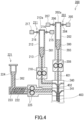
- FIG. 4 is a schematic cross-sectional view showing a POF manufacturing apparatus 200 for manufacturing a core and a clad of a POF by the optical resin formed body manufacturing method of the present embodiment.
- FIG. 5 is a cross-sectional view showing an example of a POF that can be manufactured using the apparatus 200.
- a POF 400 that can be manufactured using the apparatus 200 includes a core 401, a clad 402 disposed around the core 401, and an overclad (coating layer) 403 disposed around the clad 402.
- the apparatus 200 shown in FIG. 4 includes an extrusion apparatus 201 for forming a core, an extrusion apparatus 211 for forming a clad, and an extrusion apparatus 221 for forming an overclad.
- the apparatus 200 further includes a first chamber 240 and a second chamber 241.
- the first chamber 240 and the second chamber 241 are vertically arranged in this order from top to bottom.
- the extrusion apparatus 201 includes: a holding portion 202 that includes a cover 202a and that holds an optical resin 300 having composition suitable for the core 401 of the POF 400; and an extrusion portion 203 that extrudes the optical resin 300 held in the holding portion 202 from the holding portion 202.
- the holding portion 202 and the extrusion portion 203 respectively have the same functions as those of the holding portion 102 and the extrusion portion 103 of the apparatus 100 shown in FIG. 3 .
- the extrusion apparatus 201 is further provided with a heating portion (not illustrated) such as a heater so that the optical resin 300 can be molten in the holding portion 202 and that the molten optical resin 300 can be kept in a molten state until shaped. Because of this, for example, the optical resin (preform) 300 in a rod shape can be molten by being put in the holding portion 202 through the upper opening portion of the holding portion 202 and then being heated in the holding portion 202.
- the extrusion apparatus 201 is further provided with a gas outlet 204, a pump (e.g., a vacuum pump) 205, a gas inlet 206, and a gas supply apparatus 207.
- the gas outlet 204, the pump 205, the gas inlet 206, and the gas supply apparatus 207 have the same functions as those of the gas outlet 104, the pump 105, the gas inlet 106, and the gas supply apparatus 107 of the apparatus 100 shown in FIG. 3 and behave likewise.
- the apparatus 200 is further provided with a pressure control portion, which is not illustrated.
- the pressure control portion controls the gas outlet 204 and the pump 205 which are a depressurization mechanism and the gas inlet 206 and the gas supply apparatus 207 which are a pressurization mechanism, thereby depressurizing and pressurizing the inside of the holding portion 202 to remove a volatile component included in the optical resin 300.
- the method for depressurizing and pressurizing the inside of the holding portion 202 for removal of the volatile component is the same as that described for the depressurization in the step (i) and the pressurization in the step (ii).
- the optical resin 300 is extruded from the holding portion 202 through the extrusion portion 203, for example, by extrusion by gas.
- the optical resin 300 extruded through the extrusion portion 203 passes through, for example, a gear pump 208, then moves vertically downward, and is shaped into a fiber shape.
- the gear pump 208 has the same function as that of the gear pump 108 of the apparatus 100 shown in FIG. 3 and behaves likewise.
- the formed body delivered from the gear pump 108 and shaped into a fiber shape is supplied to the first chamber 240 and the second chamber 241 in this order.
- the extrusion apparatus 211 includes, for example, a holding portion 212 that holds an optical resin 301 having composition suitable for the clad 402 of the POF 400.
- an extrusion apparatus 210 can be used one described above as the extrusion apparatus 201. That is, the holding portion 212, an extrusion portion 213, a gas outlet 214, a pump 215, a gas inlet 216, a gas supply apparatus 217, and a gear pump 218 provided to the extrusion apparatus 210 respectively have the same functions as those of the holding portion 202, the extrusion portion 203, the gas outlet 204, the pump 205, the gas inlet 206, the gas supply apparatus 207, and the gear pump 208 provided to the extrusion apparatus 201 and behave likewise.
- the optical resin 301 delivered from the gear pump 218 is supplied to the first chamber 240.
- the clad 402 covering the outer circumference of the formed body can be formed by coating a fiber-shaped formed body with the optical resin 301 in the first chamber 240.
- the formed body coated with the clad 402 moves from the first chamber 240 to the second chamber 241.
- the extrusion apparatus 221 includes, for example, a holding portion 222 that holds a resin composition 302 having composition suitable for the overclad 403 of the POF 400, a screw 223 disposed inside the holding portion 222, and a hopper 224 connected to the holding portion 222.
- the resin composition 302 in a pellet shape is supplied to the holding portion 222 through the hopper 224.
- the resin composition 302 supplied to the holding portion 222 become soft and flowable, for example, by being kneaded by the screw 223 under heating.
- the softened resin composition 302 is extruded from the holding portion 222 by the screw 223.
- the resin composition 302 extruded from the holding portion 221 is delivered to a gear pump 225.
- the gear pump 225 adjusts the flow rate of the resin composition 302 extruded from the extrusion apparatus 221.
- the optical resin 302 delivered from the gear pump 225 is supplied to the second chamber 241.
- the overclad 403 covering the outer circumference of the clad 402 can be formed by coating the clad 402 with the resin composition 302 in the second chamber 241.
- the refractive index of the optical resin 301 forming the clad 402 of the POF 400 is preferably lower than the refractive index of the optical resin 300 forming the core 401.
- a resin material included in the optical resin 301 include the above-described fluorine-containing resins, acrylic resins such as methyl methacrylate, styrene resins, and carbonate resins.
- a resin material included in the resin composition 302 of the overclad 403 of the POF 400 include polycarbonates, various engineering plastics, cyclo-olefin polymer, polytetrafluoroethylene (PTFE), modified PTFE, and tetrafluoroethylene-perfluoroalkoxyethylene copolymer (PFA).
- the optical resin formed body manufacturing method of the present invention is also applicable as a method for shaping a common resin material into a fiber shape.
- the optical resin formed body manufacturing method of the present invention can be an invention of the following resin fiber manufacturing method by replacing the optical resin with a common resin material and shaping the resin material into a fiber shape.
- a resin fiber manufacturing method includes:
- the depressurization in the step (I) and the pressurization in the step (II) respectively correspond to the depressurization in the step (i) and the pressurization in the step (ii) in the optical resin formed body manufacturing method of the above present embodiment.
- the optical resin formed body manufacturing apparatus 100 shown in FIG. 3 can be used as an apparatus with which the above resin fiber manufacturing method is performed. That is, an invention of a resin fiber manufacturing apparatus can be defined as follows.
- a resin fiber manufacturing apparatus includes:
- the fluorine-containing polymer was a polymer obtained by polymerization of perfluoro-4-methyl-2-methylene-1 ,3-dioxolane (PFMMD).
- PFMMD perfluoro-4-methyl-2-methylene-1 ,3-dioxolane
- the produced optical resin was subjected to a depressurization and pressurization treatment using an apparatus having the same configuration as the apparatus 100 shown in FIG. 3 at different temperatures and in different pressure switching cycles ⁇ t.
- 200 g of the optical resin was placed in the holding portion 102 of the container 101, heated from ordinary temperature (25°C) to 250°C, 260°C, or 270°C at a temperature rise rate of 1 0°C/min, and then maintained at 260°C for 6 hours.
- the inside of the container 101 was depressurized to 1 kPa at a depressurization rate of 200000 Pa/min using the vacuum pump 105, and then maintained for 1 min, 5 min, or 30 min.
- the inside of the container 101 was pressurized to 0.1 MPa at a pressurization rate of 200000 Pa/min, and then maintained for 1 min, 5 min, or 30 min.
- the pressure switching cycle ⁇ t of the depressurization and the pressurization was 1 min, 5 min, and 30 min at each temperature, and the depressurization and the pressurization were alternately performed 30 times, 6 times, and once each.
- the optical resin was also subjected to a treatment in which a depressurization state at a pressure of 1 kPa was maintained for 60 min at 260°C; that is, an example was also performed in which pressurization was not performed and only depressurization was performed.
- an example was also performed in which the optical resin was maintained at ordinary pressure, namely, at a pressure of 0.1 MPa, for 60 min at 260°C. That is,
- Viscosities at a shear rate of 0.05 s -1 at 250°C, 260°C, and 270°C were measured for the optical resin in the following manner.
- a rotational rheometer "HAAKE MARS III" manufactured by Thermo Fisher Scientific K.K. was used as a measurement apparatus.
- a cone-plate geometry ( ⁇ 20 mm, 4°) was used as a geometry.
- An optical resin sample was set between the cone and the plate stable at each measurement temperature within 15 minutes or less, and then the measurement was started.
- the viscosity measurement was performed at a shear rate of 0.01 to 5 (1/s) for a measurement time of 10 min. The results are as follows.
- the optical resin formed body manufacturing method of the present invention decreases in the optical properties of the resulting optical resin formed body can be reduced and a volatile component can be efficiently removed from an optical resin. Therefore, the optical resin formed body manufacturing method of the present invention can be used, for example, for manufacturing of a POF, particularly, for manufacturing a core and a clad of a POF.
Landscapes
- Engineering & Computer Science (AREA)
- Mechanical Engineering (AREA)
- Physics & Mathematics (AREA)
- General Physics & Mathematics (AREA)
- Optics & Photonics (AREA)
- Chemical & Material Sciences (AREA)
- Health & Medical Sciences (AREA)
- Chemical Kinetics & Catalysis (AREA)
- Medicinal Chemistry (AREA)
- Polymers & Plastics (AREA)
- Organic Chemistry (AREA)
- Casting Or Compression Moulding Of Plastics Or The Like (AREA)
- Extrusion Moulding Of Plastics Or The Like (AREA)
- Optical Fibers, Optical Fiber Cores, And Optical Fiber Bundles (AREA)
- Processing And Handling Of Plastics And Other Materials For Molding In General (AREA)
Abstract
Description
- The present invention relates to an optical resin formed body manufacturing method, a resin fiber manufacturing method, and a resin fiber manufacturing apparatus.
- A method, as disclosed in
Patent Literature 1, for manufacturing a plastic optical fiber (hereinafter referred to as "POF") by heating and melting an optical resin and extrusion-molding the molten optical resin into a fiber shape is known. - Some optical resins used as raw materials in manufacturing of POFs include a volatile component. When such optical resins are molten and shaped with a volatile component therein, the resulting optical resin formed bodies include bubbles, which decrease the optical properties. Therefore, conventionally, in order to remove a volatile component in optical resins, optical resins are commonly maintained in a molten state for a certain period of time before extrusion of the molten optical resins.
- Patent Literature 1:
JP 2000-356716 A - However, long-term maintenance of optical resins in a molten state for removal of volatile components therein causes thermal decomposition of the optical resins, and thereby impurities are produced. The impurities, however, decrease the optical properties of POFs. Specifically, the impurities have refractive indices different from that of the material of a core portion of a POF, and that adversely affects an optical transmission loss in the core. Therefore, it is required to efficiently remove volatile components from optical resins in a molten state in a short period of time.
- Therefore, the present invention aims to provide an optical resin formed body manufacturing method by which decreases in the optical properties of the resulting optical resin formed body can be reduced and by which a volatile component can be efficiently removed from an optical resin. The present invention also aims to provide a resin fiber manufacturing method by which a volatile component can be efficiently removed from an optical resin and a resin fiber manufacturing apparatus with which a volatile component can be efficiently removed from an optical resin.
- An optical resin formed body manufacturing method according to a first aspect of the present invention includes:
- (i) depressurizing an inside of a container holding a molten optical resin;
- (ii) pressurizing the inside of the container holding the molten optical resin; and
- (iii) shaping the optical resin taken out of the container into a given shape,
- the steps (i) and (ii) are sequentially performed once each or are alternately performed two or more times each,
- in the step (i), a duration t1 [min] of the depressurization of the inside of the container is set such that the duration t1 and a viscosity µ1 [Pa•s] of the molten optical resin satisfy a relation µ1/t1 < 200,
- in the step (ii), a duration t2 [min] of the pressurization of the inside of the container is set such that the duration t2 and a viscosity µ2 [Pa•s] of the molten optical resin satisfy a relation µ2/t2 < 200,
- the viscosity µ1 is a viscosity of the optical resin at a shear rate of 0.05 s-1 at a temperature in the container in the step (i), and
- the viscosity µ2 is a viscosity of the optical resin at a shear rate of 0.05 s-1 at a temperature in the container in the step (ii).
- A resin fiber manufacturing method according a second aspect of the present invention includes:
- (I) depressurizing an inside of a container holding a molten resin material;
- (II) pressurizing the inside of the container holding the molten resin material; and
- (III) spinning by extruding the molten resin material out of the container to shape the molten resin material into a fiber shape, wherein
- the steps (I) and (II) are sequentially performed once each or are alternately performed two or more times each,
- in the step (I), a duration t1 [min] of the depressurization of the inside of the container is set such that the duration t1 and a viscosity µ1 [Pa•s] of the molten resin material satisfy a relation µ1/t1 < 200,
- in the step (II), a duration t2 [min] of the pressurization of the inside of the container is set such that the duration t2 and a viscosity µ2 [Pa•s] of the molten resin material satisfy a relation µ2/t2 < 200,
- the viscosity µ1 is a viscosity of the resin material at a shear rate of 0.05 s-1 at a temperature in the container in the step (I), and
- the viscosity µ2 is a viscosity of the resin material at a shear rate of 0.05 s-1 at a temperature in the container in the step (II).
- A resin fiber manufacturing apparatus according to a third aspect of the present invention includes:
- a holding portion that holds a resin material serving as a raw material of a resin fiber;
- an extrusion portion that allows the resin material held in the holding portion to be extruded out of the holding portion;
- a heating portion that heats the holding portion;
- a pressure control portion that controls a pressure in the holding portion;
- a depressurization mechanism that depressurizes an inside of the holding portion; and
- a pressurization mechanism that pressurizes the inside of the holding portion, wherein
- the pressure control portion controls the pressure in the holding portion such that depressurization and pressurization are alternately repeated at least once,
- the pressure control portion depressurizes the inside of the holding portion such that a duration t1 [min] of the depressurization of the inside of the holding portion and a viscosity µ1 [Pa•s] of the resin material that is molten satisfy a relation µ1/t1 < 200,
- the pressure control portion pressurizes the inside of the holding portion such that a duration t2 [min] of the pressurization of the inside of the holding portion and a viscosity µ2 [Pa•s] of the resin material that is molten satisfy a relation µ2/t2 < 200,
- the viscosity µ1 is a viscosity of the resin material at a shear rate of 0.05 s-1 at a temperature in the holding portion in the depressurization,
- the viscosity µ2 is a viscosity of the resin material at a shear rate of 0.05 s-1 at the temperature in the holding portion in the pressurization, and
- the resin material extruded through the extrusion portion is shaped into a fiber shape.
- By the optical resin formed body manufacturing method according to the first aspect of the present invention, decreases in the optical properties of the resulting optical resin molded article can be reduced and a volatile component can be efficiently removed from an optical resin. Moreover, a volatile component can be efficiently removed from the resin material by the resin fiber manufacturing method according to the second aspect of the present invention and with the resin fiber manufacturing apparatus according to the third aspect of the present invention.
-
-
FIG. 1A is a schematic diagram how depressurization and pressurization of an inside of a container holding a molten optical resin are alternately performed in an optical resin formed body manufacturing method according to an embodiment of the present invention. -
FIG. 1B is a schematic diagram showing expansion and shrinkage of a bubble in an optical resin and a flow of the optical resin around the bubble during alternately performed depressurization and pressurization of an inside of a container in the optical resin formed body manufacturing method according to an embodiment of the present invention. -
FIG. 2 is a graph showing an example of a relation between the time and a pressure in a container, the relation being repeated in a pressure switching cycle Δt in the optical resin formed body manufacturing method according to an embodiment of the present invention. -
FIG. 3 is a schematic cross-sectional view showing an optical resin formed body manufacturing apparatus that is an example of an apparatus with which the optical resin formed body manufacturing method according to an embodiment of the present invention can be performed. -
FIG. 4 is a schematic cross-sectional view showing a POF manufacturing apparatus for manufacturing a core and a clad of a POF by the optical resin formed body manufacturing method according to an embodiment of the present invention. -
FIG. 5 is a cross-sectional view showing an example of a POF that can be manufactured using the apparatus shown inFIG. 4 . - An embodiment of an optical resin formed body manufacturing method of the present invention will be described.
- The optical resin formed body manufacturing method of the present embodiment includes:
- (i) depressurizing an inside of a container holding a molten optical resin;
- (ii) pressurizing the inside of the container holding the molten optical resin; and
- (iii) shaping the optical resin taken out of the container into a given shape.
- In the optical resin formed body manufacturing method of the present embodiment, the depressurization of the inside of the container in the step (i) and pressurization of the inside of the container in the step (ii) are sequentially performed once each or are alternately performed two or more times each. That is, the depressurization and the pressurization are each performed at least once in the container.
- In the depressurization in the step (i), a duration t1 [min] of the depressurization of the inside of the container is set such that the duration t1 and a viscosity µ1 [Pa•s] of the molten optical resin satisfy a relation µ1/t1 < 200. The viscosity µ1 is a viscosity of the optical resin at a shear rate of 0.05 s-1 at a temperature in the container in the depressurization in the step (i).
- In the pressurization in the step (ii), a duration t2 [min] of the pressurization of the inside of the container is set such that the duration t2 and a viscosity µ2 [Pa•s] of the molten optical resin satisfy a relation µ2/t2 < 200. The viscosity µ2 is a viscosity of the optical resin at a shear rate of 0.05 s-1 at a temperature in the container in the pressurization in the step (ii).
- Each viscosity of the optical resin at a shear rate of 0.05 s-1 is a value measured by a rotational viscosity measurement method, and is measured using a rotational rheometer.
- According to the above optical resin formed body manufacturing method of the present embodiment, without maintaining the optical resin in a molten state for a long period of time, a volatile component therein can be efficiently removed from the optical resin by depressurizing and pressurizing the inside of the container holding the molten optical resin under the above conditions. Consequently, inclusion of impurities produced by thermal decomposition of the optical resin in the resulting optical resin formed body can be reduced. That is, according to the optical resin formed body manufacturing method of the present embodiment, decreases in the optical properties of the resulting optical resin formed body can be reduced and the volatile component can be efficiently removed from the optical resin. Additionally, since the volatile component is removed from the optical resin, the optical resin formed body to be manufactured includes almost no bubbles. Because of these, an optical resin formed body for which decreases in optical properties are reduced and which has excellent optical properties can be manufactured efficiently by the optical resin formed body manufacturing method of the embodiment.
- The reason why the volatile component can be efficiently removed from the optical resin by depressurizing and pressurizing the inside of the container holding the molten optical resin is as follows.
FIG. 1A is a schematic diagram showing how depressurization and pressurization of an inside of acontainer 2 holding a moltenoptical resin 1 are alternately performed.FIG. 1B shows expansion and shrinkage of abubble 3 in theoptical resin 1 and a flow of the optical resin around thebubble 3 during alternately performed depressurization and pressurization of the inside of thecontainer 2. In an example shown inFIG. 1A , the inside of thecontainer 1 is depressurized using a vacuum pump and pressurized by introducing a gas into thecontainer 1. By sequentially performing the depressurization and the pressurization of the moltenoptical resin 1 once each or, preferably, alternately performing the depressurization and the pressurization of the moltenoptical resin 1 two or more times each, preferably two or more times each, thebubble 3 generated in the moltenoptical resin 1 repeatedly undergoes expansion and shrinkage (an arrow A inFIG. 1B ). That causes theoptical resin 1 around thebubble 3 to flow (an arrow B inFIG. 1B ). When the moltenoptical resin 1 is a fluid, namely a non-Newtonian fluid, whose viscosity depends on the shear rate, the flow of theoptical resin 1 around thebubble 3 increases the shear rate of theoptical resin 1 around thebubble 3 and decreases an apparent viscosity of theoptical resin 1 around thebubble 3. The decrease in the apparent viscosity promotes rise of thebubble 3, making it easy for thebubble 3 to escape from theoptical resin 1. Therefore, the volatile component can be efficiently removed from theoptical resin 1 without maintaining theoptical resin 1 in a molten state for a long period of time. It is thought that even when the moltenoptical resin 1 is a Newtonian fluid, the volatile component can be efficiently removed from theoptical resin 1 owing to the following advantages. The advantages are, for example, as follows: (1) the bubble rises at a higher rate due to an increase in the diameter of the bubble in the depressurization, and that makes it easy for the bubble to escape from the optical resin; (2) the bubble that failed to escape from the optical resin in the depressurization and that is at a gas-liquid interface (top layer of a surface of the molten optical resin) of the optical resin bursts in the pressurization to be removed from the optical resin. - The optical resin formed body manufacturing method of the present embodiment will be described in more details.
- As described above, in the depressurization in the step (i), the duration t1 [min] is required to be set such that the duration t1 and the viscosity µ1 [Pa•s] of the molten optical resin satisfy the relation µ1/t1 < 200. It is preferred that the duration t1 [min] and the viscosity µ1 [Pa•s] satisfy µ1/t1 ≤ 180. The preferred lower limit of µ1/t1 is not limited to a particular value, and may be, for example, 1 or greater, and is preferably 6 or greater.
- As described above, in the pressurization in the step (ii), the duration t2 [min] is required to be set such that the duration t2 and the viscosity µ2 [Pa•s] of the molten optical resin satisfy the relation µ2/t2 < 200. It is preferred that the duration t2 [min] and the viscosity µ2 [Pa•s] satisfy µ2/t2 ≤ 180. The preferred lower limit of µ2/t2 is not limited to a particular value, and may be, for example, 1 or greater, and is preferably 6 or greater.
- In the optical resin formed body manufacturing method of the present embodiment, the depressurization of the inside of the container in the step (i) and the pressurization of the inside of the container in the step (ii) are required to be sequentially performed once each or alternately performed two or more times each. However, as described above, the depressurization and the pressurization are preferably alternately performed two or more times each to decrease the apparent viscosity of the optical resin in the container and allow the bubble in the optical resin to escape more easily. For example, the depressurization and the pressurization are preferably alternately performed six or more times each. Because the depressurization and the pressurization are preferably repeated until the volatile component in the optical resin are removed as much as possible, the preferred upper limit of the number of times that the depressurization is repeated and the preferred upper limit of the number of time that the pressurization is repeated are not limited to particular values. In one example, the number of times that the depressurization is repeated and the number of time that the pressurization is repeated may each be 100 times or less.
- The depressurization of the inside of the container in the step (i) and the pressurization of the inside of the container in the step (ii) may be alternately performed in a pressure switching cycle Δt. The pressure switching cycle Δt refers to a time interval at which the depressurization and the pressurization of the inside of the container are switched. That is, in the case where the depressurization and the pressurization of the inside of the container are alternately performed in the pressure switching cycle Δt, the duration t1 of the depressurization of the inside of the container in the step (i) and the duration t2 of the pressurization of the inside of the container in the step (ii) are each the pressure switching cycle Δt.
FIG. 2 shows a graph showing an example of a relation between the time and the pressure, the graph being obtained by repeating, in the pressure switching cycle Δt, depressurization of the inside of the container from an initial pressure P0 (e.g., ordinary pressure) to a pressure P1, pressurization of the inside of the container to the initial pressure P0, depressurization to the pressure P1, and pressurization to the initial pressure P0. In the example shown inFIG. 2 , the inside of the container is depressurized to the same pressure P1 by the repeated depressurization, and the pressure is returned back to the initial pressure P0 by the repeated pressurization. However, the relation between the time and the pressure is not limited to this example. In the case where the depressurization step and the pressurization step are repeated, the pressure to which the inside of the container is depressurized may be different from one depressurization step to another, and the pressure to which the inside of the container is pressurized may be different from one pressurization step to another. - The duration t1 and the duration t2 are each preferably, for example, 5 min or more and 30 min or less, more preferably 5 min or more and 20 min or less. The duration t1 and the duration t2 in the above range make it possible to efficiently remove the volatile component from the optical resin.
- In the case where the depressurization of the inside of the container in the step (i) and the pressurization of the inside of the container in the step (ii) are alternately performed in the pressure switching cycle Δt, the pressure switching cycle Δt is preferably, for example, 5 min or more and 30 min or less. The pressure switching cycle Δt in the above range makes it possible to efficiently remove the volatile component from the optical resin.
- The order of the depressurization and the pressurization is not particularly limited. That is, the pressure inside the container may be controlled in the order from depressurization, to pressurization, to depressurization, to pressurization, to depressurization, to pressurization ... or in the order from pressurization, to depressurization, to pressurization, to depressurization, to pressurization, to depressurization .... However, in terms of the solubility of a gas in the molten optical resin, the inside of the container is preferably depressurized first, and then pressurized. For example, an initial pressure of the inside of the container holding the molten optical resin may be ordinary pressure, and the inside of the container at the ordinary pressure may be depressurized, and then pressurized to a pressure lower than the ordinary pressure.
- A ratio of the maximum pressure in the container in the pressurization in the step (ii) to the minimum pressure in the container in the depressurization in the step (i) ((the maximum pressure of the inside of the container in the pressurization)/(the minimum pressure in the container in the depressurization); hereinafter referred to as "pressure ratio in the container") is preferably, for example, 100 or more. The pressure ratio in the container set in this range allows the volatile component to be efficiently removed from the optical resin. The preferred upper limit of the pressure ratio in the container is not limited to a particular value. In one example, the pressure ratio in the container is 10000 or less.
- In the step (i), the minimum pressure in the container is preferably 0.01 kPa to 1 kPa.
- In the step (ii), the maximum pressure in the container is preferably 0.01 MPa to 0.5 MPa.
- A depressurization rate at which the inside of the container is depressurized and a pressurization rate at which the inside of the container is pressurized are not limited to particular values. However, the depressurization rate is preferably 10 to 600 kPa/min to efficiently cause the optical resin to flow around the bubble in the optical resin and increase the shear rate of the optical resin around the bubble. For the same reason, the pressurization rate is preferably 10 to 600 kPa/min.
- As described above, the viscosity µ1 is a viscosity of the optical resin at a shear rate of 0.05 s-1 at a temperature of the inside of the container in the depressurization in the step (i), and the viscosity µ2 is a viscosity of the optical resin at a shear rate of 0.05 s-1 at a temperature of the inside of the container in the depressurization in the step (ii). Therefore, in the case where the temperature in the container does not vary throughout the depressurization and the pressurization, the viscosity µ1 and the viscosity µ2 of the optical resin are the same.
- The viscosity µ1 and the viscosity µ2 are each preferably 100 Pa•s or more and 1000 Pa•s or less, more preferably 100 Pa•s or more and 900 Pa•s or less. When the viscosity of the optical resin at a shear rate of 0.05 s-1 is in the above range, the volatile component can be efficiently removed from the optical resin by repeating the depressurization and the pressurization.
- The optical resin may be, for example, supplied in a rod shape into the container and heated in the container to be molten, and, subsequently, the depressurization and the pressurization of the inside of the container may be performed. Alternatively, the optical resin in a molten state may be supplied into the container, and, subsequently, the depressurization and the pressurization of the inside of the container may be performed. However, melting of the optical resin in the container and subsequent debubbling in the same container by means of the depressurization and the pressurization make it possible to efficiently manufacture an optical resin formed body without further introduction of impurities and a volatile component.
- In the optical resin formed body manufacturing method of the present embodiment, the temperature in the container in which the depressurization in the step (i) and the pressurization in the step (ii) are performed depends also on a glass transition temperature, etc. of the optical resin used, and is thus not limited to a particular value. When the optical resin used includes a later-described fluorine-containing polymer, for example, the depressurization in the step (i) and the pressurization in the step (ii) are preferably performed at a temperature of 200 to 300°C.
-
FIG. 3 is a schematic cross-sectional view showing an optical resin formedbody manufacturing apparatus 100 which is an exemplary apparatus with which the optical resin formed body manufacturing method of the present embodiment can be performed.FIG. 3 illustrates an example in which an optical resin formed body is shaped into a fiber shape. - The
apparatus 100 shown inFIG. 3 includes acontainer 101. Thecontainer 101 includes: a holdingportion 102 that holds theoptical resin 1; and anextrusion portion 103 that extrudes theoptical resin 1 held in the holdingportion 102 from the holdingportion 102. The holdingportion 102 is a tubular body having opening portions at its upper part and its lower part. The holdingportion 102 includes acover 102a. The upper opening portion of the holdingportion 102 is closed by thecover 102a. The lower opening portion of the holdingportion 102 is formed to discharge the moltenoptical resin 1 held in the holdingportion 102 to an outside of the holdingportion 102. That is, the lower opening portion of the holdingportion 102 forms theextrusion portion 103. Theapparatus 100 is further provided with a heating portion (not illustrated) such as a heater so that theoptical resin 1 can be molten in the holdingportion 102 and that the moltenoptical resin 1 can be kept in a molten state until shaped. Because of this, for example, the optical resin (preform) 1 in a rod shape can be molten by being put in the holdingportion 102 through the upper opening portion of the holdingportion 102 and then being heated in the holdingportion 102. - The
container 101 is further provided with agas outlet 104 for discharging a gas in the holdingportion 102 and a pump (e.g., a vacuum pump) 105 connected to thegas outlet 104 and configured to discharge the gas in the holdingportion 102. That is, in theapparatus 100, thegas outlet 104 and thepump 105 compose a depressurization mechanism that depressurizes the inside of the holdingportion 102. Thecontainer 101 is further provided with agas inlet 106 for introducing a gas (e.g., nitrogen gas) into the holdingportion 102 and agas supply apparatus 107 connected to thegas inlet 106 and configured to supply the gas into the holdingportion 102. That is, in theapparatus 100, thegas inlet 106 and thegas supply apparatus 107 compose a pressurization mechanism that pressurizes the inside of the holdingportion 102. - In the
apparatus 100, theoptical resin 1 is extruded from the holdingportion 102 through theextrusion portion 103, for example, by extrusion by gas. The above pressurization mechanism can be used to extrude theoptical resin 1. That is, by introducing a gas (e.g., nitrogen gas) into the holdingportion 102 from thegas supply apparatus 107 through thegas inlet 106, the pressure in the holdingportion 102 is increased to extrude the moltenoptical resin 1 from the holdingportion 102 through theextrusion portion 103. Theoptical resin 1 extruded through theextrusion portion 103 passes through, for example, agear pump 108. Theoptical resin 1 having passed through thegear pump 108, for example, moves vertically downward and is shaped into a fiber shape. Thegear pump 108 is provided to adjust the flow rate of the extrudedoptical resin 1. Since a fluctuation of the flow rate of theoptical resin 1 can be reduced by allowing theoptical resin 1 to pass through thegear pump 108, the fiber-shaped formed body can have a uniform thickness. - The
apparatus 100 is further provided with a pressure control portion, which is not illustrated. The pressure control portion controls the above-described depressurization mechanism and pressurization mechanism, thereby depressurizing and pressurizing the inside of the holdingportion 102 holding the moltenoptical resin 1 to remove a volatile component included in theoptical resin 1. - When the optical resin formed body manufacturing method of the present embodiment is performed using the
apparatus 100, the depressurization in the step (i) and the pressurization in the step (ii) are performed in the holdingportion 102. The method for depressurizing and pressurizing the inside of the holdingportion 102 to remove the volatile component from theoptical resin 1 is as described above. In addition, taking out and shaping of the optical resin in the step (iii) are performed by extruding the moltenoptical resin 1 held in the holdingportion 102 to the outside of the holdingportion 102 through theextrusion portion 103. - The volatile component removed from the
optical resin 1 by the above-described depressurization and pressurization of the inside of the holdingportion 102 is removed to the outside of the holdingportion 102, namely, an outside of thecontainer 101, in the depressurization during the repetition of the depressurization and the pressurization of the inside of the holdingportion 102. To remove the volatile component removed from theoptical resin 1 to the outside of the holdingportion 102, the inside of the holdingportion 102 is desirably depressurized just before theoptical resin 1 is extruded from the holdingportion 102. - The optical resin used in the optical resin formed body manufacturing method of the present embodiment includes, for example, a fluorine-containing polymer. The fluorine-containing polymer is used for an optical member, such as a POF or an exposure member, or as a surface modifier or the like. The fluorine-containing polymer is a useful substance used in a wide range of fields. Therefore, an optical resin formed body manufactured by the manufacturing method of the present embodiment using the optical resin including the fluorine-containing polymer can be used as an optical member such as a POF. The optical resin formed body manufactured by the manufacturing method of the present embodiment may be, for example, a member included in a POF. The optical resin formed body manufactured by the manufacturing method of the present embodiment may be at least one selected from the group consisting of a core of a POF and a clad of a POF.
- When the optical resin includes the fluorine-containing polymer in the present embodiment, it is preferred from the viewpoint of reducing light absorption attributable to stretching energy of a C-H bond that the fluorine-containing polymer be substantially free of a hydrogen atom, and it is particularly preferred that every hydrogen atom bonded to a carbon atom be substituted by a fluorine atom. That is, it is preferred that the fluorine-containing polymer included in the optical resin be substantially free of a hydrogen atom and be fully fluorinated. Herein, saying that the fluorine-containing polymer is substantially free of a hydrogen atom means that the content of a hydrogen atom in the fluorine-containing polymer is 1 mol% or less.
- The fluorine-containing polymer preferably has a fluorine-containing aliphatic ring structure. The fluorine-containing aliphatic ring structure may be included in a main chain of the fluorine-containing polymer, or may be included in a side chain of the fluorine-containing polymer. The fluorine-containing polymer has, for example, a structural unit (A) represented by the following structural formula (1).

- In the formula (1), Rff 1 to Rff 4 each independently represent a fluorine atom, a perfluoroalkyl group having 1 to 7 carbon atoms, or a perfluoroalkyl ether group having 1 to 7 carbon atoms. Rff 1 and Rff 2 are optionally linked to form a ring. "Perfluoro" indicates that every hydrogen atom bonded to a carbon atom is substituted by a fluorine atom. In the formula (1), the number of carbon atoms in the perfluoroalkyl group is preferably 1 to 5, more preferably 1 to 3, and even more preferably 1. The perfluoroalkyl group may be linear or branched. Examples of the perfluoroalkyl group include a trifluoromethyl group, a pentafluoroethyl group, and a heptafluoropropyl group.
- In the formula (1), the number of carbon atoms in the perfluoroalkyl ether group is preferably 1 to 5 and more preferably 1 to 3. The perfluoroalkyl ether group may be linear or branched. Examples of the perfluoroalkyl ether group include a perfluoromethoxymethyl group.
- When Rff 1 and Rff 2 are linked to form a ring, the ring may be a five-membered ring or a six-membered ring. Examples of the ring include a perfluorotetrahydrofuran ring, a perfluorocyclopentane ring, and a perfluorocyclohexane ring.
- Specific examples of the structural unit (A) include structural units represented by the following formulae (A1) to (A8).


- Among the structural units represented by the above formulae (A1) to (A8), the structural unit (A) is preferably the structural unit (A2), i.e., a structural unit represented by the following formula (2).

- The fluorine-containing polymer may include one or more structural units (A).
- In the fluorine-containing polymer, the content of the structural unit (A) is preferably 20 mol% or more and more preferably 40 mol% or more relative to a total content of all structural units. When including 20 mol% or more of the structural unit (A), the fluorine-containing polymer tends to have much higher thermal resistance. When including 40 mol% or more of the structural unit (A), the fluorine-containing polymer tends to have much higher transparency and much higher mechanical strength in addition to high thermal resistance. In the fluorine-containing polymer, the content of the structural unit (A) is preferably 95 mol% or less and more preferably 70 mol% or less relative to the total content of all structural units.
- The structural unit (A) is derived from, for example, a compound represented by the following formula (3). In the formula (3), Rff 1 to Rff 4 are as described for the formula (1). It should be noted that the compound represented by the formula (3) can be obtained, for example, by an already-known manufacturing method such as a manufacturing method disclosed in
JP 2007-504125 A 
- Specific examples of the compound represented by the above formula (3) include compounds represented by the following formulae (M1) to (M8).


- The fluorine-containing polymer may further include an additional structural unit other than the structural unit (A). Examples of the additional structural unit include the following structural units (B) to (D).
- The structural unit (B) is represented by the following formula (4).

- In the formula (4), R1 to R3 each independently represents a fluorine atom or a perfluoroalkyl group having 1 to 7 carbon atoms. R4 represents a perfluoroalkyl group having 1 to 7 carbon atoms. The perfluoroalkyl group may have a ring structure. One or some of the fluorine atoms may be substituted by a halogen atom other than a fluorine atom. One or some of fluorine atoms in the perfluoroalkyl group may be substituted by a halogen atom other than a fluorine atom.
- The fluorine-containing polymer may include one or more structural units (B). In the fluorine-containing polymer, the content of the structural unit (B) is preferably 5 to 10 mol% relative to the total content of all structural units. The content of the structural unit (B) may be 9 mol% or less or 8 mol% or less.
- The structural unit (B) is derived from, for example, a compound represented by the following formula (5). In the formula (5), R1 to R4 are as described for the formula (4). The compound represented by the formula (5) is a fluorine-containing vinyl ether such as perfluorovinyl ether.

- The structural unit (C) is represented by the following formula (6).
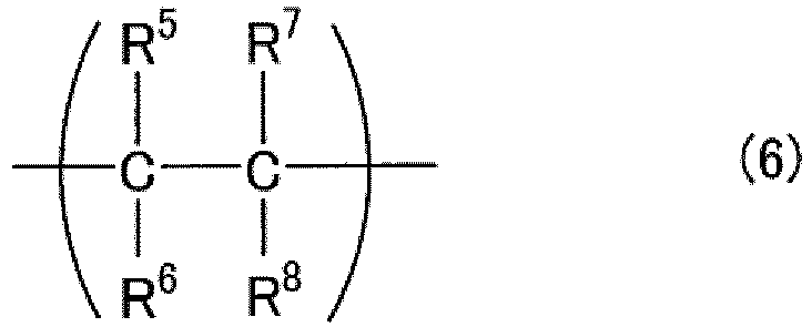
- In the formula (6), R5 to R8 each independently represents a fluorine atom or a perfluoroalkyl group having 1 to 7 carbon atoms. The perfluoroalkyl group may have a ring structure. One or some of the fluorine atoms may be substituted by a halogen atom other than a fluorine atom. One or some of fluorine atoms in the perfluoroalkyl group may be substituted by a halogen atom other than a fluorine atom.
- The fluorine-containing polymer may include one or more structural units (C). In the fluorine-containing polymer, the content of the structural unit (C) is preferably 5 to 10 mol% relative to the total content of all structural units. The content of the structural unit (C) may be 9 mol% or less or 8 mol% or less.
- The structural unit (C) is derived from, for example, a compound represented by the following formula (7). In the formula (7), R5 to R8 are as described for the formula (6). The compound represented by the formula (7) is a fluorine-containing olefin such as tetrafluoroethylene or chlorotrifluoroethylene.

- The structural unit (D) is represented by the following formula (8).

- In the formula (8), Z represents an oxygen atom, a single bond, or -OC(R19R20)O-, R9 to R20 each independently represent a fluorine atom, a perfluoroalkyl group having 1 to 5 carbon atoms, or a perfluoroalkoxy group having 1 to 5 carbon atoms. One or some of the fluorine atoms may be substituted by a halogen atom other than a fluorine atom. One or some of fluorine atoms in the perfluoroalkyl group may be substituted by a halogen atom other than a fluorine atom. One or some of fluorine atoms in the perfluoroalkoxy group may be substituted by a halogen atom other than a fluorine atom. Symbols s and t are each independently 0 to 5, and s + t is an integer of 1 to 6 (when Z is -OC(R19R20)O-, s + t may be 0).
- The structural unit (D) is preferably represented by the following formula (9). The structural unit represented by the following formula (9) is a structural unit represented by the above formula (8), where Z is an oxygen atom, s is 0, and t is 2.

- In the formula (9), R141, R142, R151, and R152 are each independently a fluorine atom, a perfluoroalkyl group having 1 to 5 carbon atoms, or a perfluoroalkoxy group having 1 to 5 carbon atoms. One or some of the fluorine atoms may be substituted by a halogen atom other than a fluorine atom. One or some of fluorine atoms in the perfluoroalkyl group may be substituted by a halogen atom other than a fluorine atom. One or some of fluorine atoms in the perfluoroalkoxy group may be substituted by a halogen atom other than a fluorine atom.
- The fluorine-containing polymer may include one or more structural units (D). In the fluorine-containing polymer, the content of the structural unit (D) is preferably 30 to 67 mol% relative to the total content of all structural units. The content of the structural unit (D) is, for example, 35 mol% or more, may be 60 mol% or less or 55 mol% or less.
- The structural unit (D) is, for example, derived from a compound represented by the following formula (10). In the formula (10), Z, R9 to R18, s, and t are as described for the formula (8). The compound represented by the formula (10) is a cyclopolymerizable fluorine-containing compound having two or more polymerizable double bonds.

- The structural unit (D) is preferably derived from a compound represented by the following formula (11). In the formula (11), R141, R142, R151, and R152 are as described for the formula (9).

- Specific examples of the compound represented by the formula (10) or the formula (11) include the following compounds.
CF2=CFOCF2CF=CF2
CF2=CFOCF(CF3)CF=CF2
CF2=CFOCF2CF2CF=CF2
CF2=CFOCF2CF(CF3)CF=CF2
CF2=CFOCF(CF3)CF2CF=CF2
CF2=CFOCFClCF2CF=CF2
CF2=CFOCCl2CF2CF=CF2
CF2=CFOCF2OCF=CF2
CF2=CFOC(CF3)2OCF=CF2
CF2=CFOCF2CF(OCF3)CF=CF2
CF2=CFCF2CF=CF2
CF2=CFCF2CF2CF=CF2
CF2=CFCF2OCF2CF=CF2
CF2=CFOCF2CFClCF=CF2
CF2=CFOCF2CF2CCl=CF2
CF2=CFOCF2CF2CF=CFCl
CF2=CFOCF2CF(CF3)CCl=CF2
CF2=CFOCF2OCF=CF2
CF2=CFOCCl2OCF=CF2
CF2=CClOCF2OCCl=CF2
- The fluorine-containing copolymer of the present embodiment may further include an additional structural unit other than the structural units (A) to (D). However, the fluorine-containing copolymer of the present embodiment is preferably substantially free of an additional structural unit other than the structural units (A) to (D). That the fluorine-containing polymer is substantially free of an additional structural unit other than the structural units (A) to (D) means that a total content of the structural units (A) to (D) is 95 mol% or more and preferably 98 mol% or more relative to the total content of all structural units in the fluorine-containing polymer.
- The method for polymerizing the fluorine-containing polymer is not limited to a particular one, and a common polymerization method such as radical polymerization can be used. A polymerization initiator for the polymerization of the fluorine-containing polymer may be a fully-fluorinated compound.
- A glass transition temperature (Tg) of the fluorine-containing polymer is, for example, but not particularly limited to, 100°C to 140°C, and may be 105°C or higher or 120°C or higher. The term "Tg" herein refers to a midpoint glass transition temperature (Tmg) determined according to JIS K 7121: 1987.
- The optical resin may include the fluorine-containing polymer as a main component, and preferably consists essentially of the fluorine-containing polymer.
- The optical resin may further include an additive in addition to the fluorine-containing polymer. The additive is, for example, a refractive index modifier. As the refractive index modifier can be used, for example, a known refractive index modifier used for a resin composition used as the material of an optical member. For example, when the optical resin used in the optical resin formed body manufacturing method of the present embodiment is used as the material of a POF, the optical resin used in the optical resin formed body manufacturing method of the present embodiment can include a known refractive index modifier used as the material of a POF. The optical resin may include an additive other than the refractive index modifier.
- An example in which an optical resin formed body to be manufactured is a core and a clad of a POF will be described as another example of the optical resin formed body manufacturing method of the present embodiment.
-
FIG. 4 is a schematic cross-sectional view showing aPOF manufacturing apparatus 200 for manufacturing a core and a clad of a POF by the optical resin formed body manufacturing method of the present embodiment. -
FIG. 5 is a cross-sectional view showing an example of a POF that can be manufactured using theapparatus 200. APOF 400 that can be manufactured using theapparatus 200 includes acore 401, a clad 402 disposed around thecore 401, and an overclad (coating layer) 403 disposed around the clad 402. - The
apparatus 200 shown inFIG. 4 includes anextrusion apparatus 201 for forming a core, anextrusion apparatus 211 for forming a clad, and anextrusion apparatus 221 for forming an overclad. Theapparatus 200 further includes afirst chamber 240 and asecond chamber 241. Thefirst chamber 240 and thesecond chamber 241 are vertically arranged in this order from top to bottom. - The
extrusion apparatus 201 includes: a holdingportion 202 that includes acover 202a and that holds anoptical resin 300 having composition suitable for thecore 401 of thePOF 400; and anextrusion portion 203 that extrudes theoptical resin 300 held in the holdingportion 202 from the holdingportion 202. The holdingportion 202 and theextrusion portion 203 respectively have the same functions as those of the holdingportion 102 and theextrusion portion 103 of theapparatus 100 shown inFIG. 3 . Theextrusion apparatus 201 is further provided with a heating portion (not illustrated) such as a heater so that theoptical resin 300 can be molten in the holdingportion 202 and that the moltenoptical resin 300 can be kept in a molten state until shaped. Because of this, for example, the optical resin (preform) 300 in a rod shape can be molten by being put in the holdingportion 202 through the upper opening portion of the holdingportion 202 and then being heated in the holdingportion 202. - The
extrusion apparatus 201 is further provided with agas outlet 204, a pump (e.g., a vacuum pump) 205, agas inlet 206, and agas supply apparatus 207. Thegas outlet 204, thepump 205, thegas inlet 206, and thegas supply apparatus 207 have the same functions as those of thegas outlet 104, thepump 105, thegas inlet 106, and thegas supply apparatus 107 of theapparatus 100 shown inFIG. 3 and behave likewise. Theapparatus 200 is further provided with a pressure control portion, which is not illustrated. The pressure control portion controls thegas outlet 204 and thepump 205 which are a depressurization mechanism and thegas inlet 206 and thegas supply apparatus 207 which are a pressurization mechanism, thereby depressurizing and pressurizing the inside of the holdingportion 202 to remove a volatile component included in theoptical resin 300. The method for depressurizing and pressurizing the inside of the holdingportion 202 for removal of the volatile component is the same as that described for the depressurization in the step (i) and the pressurization in the step (ii). - In the
apparatus 201, theoptical resin 300 is extruded from the holdingportion 202 through theextrusion portion 203, for example, by extrusion by gas. Theoptical resin 300 extruded through theextrusion portion 203 passes through, for example, agear pump 208, then moves vertically downward, and is shaped into a fiber shape. Thegear pump 208 has the same function as that of thegear pump 108 of theapparatus 100 shown inFIG. 3 and behaves likewise. The formed body delivered from thegear pump 108 and shaped into a fiber shape is supplied to thefirst chamber 240 and thesecond chamber 241 in this order. - The
extrusion apparatus 211 includes, for example, a holdingportion 212 that holds anoptical resin 301 having composition suitable for the clad 402 of thePOF 400. As an extrusion apparatus 210 can be used one described above as theextrusion apparatus 201. That is, the holdingportion 212, anextrusion portion 213, agas outlet 214, apump 215, agas inlet 216, agas supply apparatus 217, and agear pump 218 provided to the extrusion apparatus 210 respectively have the same functions as those of the holdingportion 202, theextrusion portion 203, thegas outlet 204, thepump 205, thegas inlet 206, thegas supply apparatus 207, and thegear pump 208 provided to theextrusion apparatus 201 and behave likewise. - The
optical resin 301 delivered from thegear pump 218 is supplied to thefirst chamber 240. The clad 402 covering the outer circumference of the formed body can be formed by coating a fiber-shaped formed body with theoptical resin 301 in thefirst chamber 240. The formed body coated with the clad 402 moves from thefirst chamber 240 to thesecond chamber 241. - The
extrusion apparatus 221 includes, for example, a holdingportion 222 that holds aresin composition 302 having composition suitable for theoverclad 403 of thePOF 400, ascrew 223 disposed inside the holdingportion 222, and ahopper 224 connected to the holdingportion 222. In theextrusion apparatus 221, for example, theresin composition 302 in a pellet shape is supplied to the holdingportion 222 through thehopper 224. Theresin composition 302 supplied to the holdingportion 222 become soft and flowable, for example, by being kneaded by thescrew 223 under heating. The softenedresin composition 302 is extruded from the holdingportion 222 by thescrew 223. - The
resin composition 302 extruded from the holdingportion 221 is delivered to agear pump 225. Thegear pump 225 adjusts the flow rate of theresin composition 302 extruded from theextrusion apparatus 221. - The
optical resin 302 delivered from thegear pump 225 is supplied to thesecond chamber 241. Theoverclad 403 covering the outer circumference of the clad 402 can be formed by coating the clad 402 with theresin composition 302 in thesecond chamber 241. - The refractive index of the
optical resin 301 forming the clad 402 of thePOF 400 is preferably lower than the refractive index of theoptical resin 300 forming thecore 401. Examples of a resin material included in theoptical resin 301 include the above-described fluorine-containing resins, acrylic resins such as methyl methacrylate, styrene resins, and carbonate resins. Examples of a resin material included in theresin composition 302 of theoverclad 403 of thePOF 400 include polycarbonates, various engineering plastics, cyclo-olefin polymer, polytetrafluoroethylene (PTFE), modified PTFE, and tetrafluoroethylene-perfluoroalkoxyethylene copolymer (PFA). - The invention of the optical resin formed body manufacturing method has been described in present embodiment. However, the optical resin formed body manufacturing method of the present invention is also applicable as a method for shaping a common resin material into a fiber shape. For example, the optical resin formed body manufacturing method of the present invention can be an invention of the following resin fiber manufacturing method by replacing the optical resin with a common resin material and shaping the resin material into a fiber shape.
- A resin fiber manufacturing method includes:
- (I) depressurizing an inside of a container holding a molten resin material;
- (II) pressurizing the inside of the container holding the molten resin material; and
- (III) spinning by extruding the molten resin material out of the container to shape the molten resin material into a fiber shape, wherein
- the steps (I) and (II) are sequentially performed once each or are alternately performed two or more times each,
- in the step (I), a duration t1 [min] of the depressurization of the inside of the container is set such that the duration t1 and a viscosity µ1 [Pa•s] of the molten resin material satisfy a relation µ1/t1 < 200,
- in the step (II), a duration t2 [min] of the pressurization of the inside of the container is set such that the duration t2 and a viscosity µ2 [Pa•s] of the molten resin material satisfy a relation µ2/t2 < 200,
- the viscosity µ1 is a viscosity of the resin material at a shear rate of 0.05 s-1 at a temperature in the container in the step (I), and
- the viscosity µ2 is a viscosity of the resin material at a shear rate of 0.05 s-1 at a temperature in the container in the step (II).
- In the above resin fiber manufacturing method, the depressurization in the step (I) and the pressurization in the step (II) respectively correspond to the depressurization in the step (i) and the pressurization in the step (ii) in the optical resin formed body manufacturing method of the above present embodiment.
- Moreover, the optical resin formed
body manufacturing apparatus 100 shown inFIG. 3 can be used as an apparatus with which the above resin fiber manufacturing method is performed. That is, an invention of a resin fiber manufacturing apparatus can be defined as follows. - A resin fiber manufacturing apparatus includes:
- a holding portion that holds a resin material serving as a raw material of a resin fiber;
- an extrusion portion that allows the resin material held in the holding portion to be extruded out of the holding portion;
- a heating portion that heats the holding portion;
- a pressure control portion that controls a pressure in the holding portion;
- a depressurization mechanism that depressurizes an inside of the holding portion; and
- a pressurization mechanism that pressurizes the inside of the holding portion, wherein
- the pressure control portion controls the pressure in the holding portion such that depressurization and pressurization are alternately repeated at least once,
- the pressure control portion depressurizes the inside of the holding portion such that a duration t1 [min] of the depressurization of the inside of the holding portion and a viscosity µ1 [Pa•s] of the resin material that is molten satisfy a relation µ1/t1 < 200,
- the pressure control portion pressurizes the inside of the holding portion such that a duration t2 [min] of the pressurization of the inside of the holding portion and a viscosity µ2 [Pa•s] of the resin material that is molten satisfy a relation µ2/t2 < 200,
- the viscosity µ1 is a viscosity of the resin material at a shear rate of 0.05 s-1 at a temperature in the holding portion in the depressurization,
- the viscosity µ2 is a viscosity of the resin material at a shear rate of 0.05 s-1 at the temperature in the holding portion in the pressurization, and
- the resin material extruded through the extrusion portion is shaped into a fiber shape.
- Hereinafter, the present invention will be described in more detail by way of examples. The present invention is not limited to the following examples.
- A fluorine-containing polymer formed of the above structural unit (A2), i.e., the structural unit represented by the above formula (2), was produced as an optical resin. The fluorine-containing polymer was a polymer obtained by polymerization of perfluoro-4-methyl-2-methylene-1 ,3-dioxolane (PFMMD). The production method was specifically as follows.
- An amount of 10 g of PFMMD and 80 mg of perfluorobenzoyl peroxide were sealed in a glass tube. This glass tube was subjected to three cycles of degassing using a freeze-thaw vacuum machine and was charged again with argon. The glass tube was sealed and then heated for 1 day at 50°C. The contents of the glass tube were thereby turned into a solid. The glass tube was further heated for 4 days at 70°C to obtain 10 g of a transparent stick-like body. A portion of the transparent stick-like body was dissolved in a hexafluorobenzene solution, to which chloroform was added to cause precipitation for purification. Solution polymerization of the monomer was performed in Fluorinert FC-75 (manufactured by Sumitomo 3M Ltd.) using perfluorobenzoyl peroxide as an initiator. A PFMMD polymer was obtained thereby.
- The produced optical resin was subjected to a depressurization and pressurization treatment using an apparatus having the same configuration as the
apparatus 100 shown inFIG. 3 at different temperatures and in different pressure switching cycles Δt. First, 200 g of the optical resin was placed in the holdingportion 102 of thecontainer 101, heated from ordinary temperature (25°C) to 250°C, 260°C, or 270°C at a temperature rise rate of 1 0°C/min, and then maintained at 260°C for 6 hours. Next, the inside of thecontainer 101 was depressurized to 1 kPa at a depressurization rate of 200000 Pa/min using thevacuum pump 105, and then maintained for 1 min, 5 min, or 30 min. Then, nitrogen gas was led to the inside of thecontainer 101 using thegas supply apparatus 107, the inside of thecontainer 101 was pressurized to 0.1 MPa at a pressurization rate of 200000 Pa/min, and then maintained for 1 min, 5 min, or 30 min. The pressure switching cycle Δt of the depressurization and the pressurization was 1 min, 5 min, and 30 min at each temperature, and the depressurization and the pressurization were alternately performed 30 times, 6 times, and once each. Moreover, the optical resin was also subjected to a treatment in which a depressurization state at a pressure of 1 kPa was maintained for 60 min at 260°C; that is, an example was also performed in which pressurization was not performed and only depressurization was performed. Furthermore, an example was also performed in which the optical resin was maintained at ordinary pressure, namely, at a pressure of 0.1 MPa, for 60 min at 260°C. That is, - (1) the optical resins subjected to the depressurization and the pressurization alternately performed 30 times each in a pressure switching cycle of 1 min,
- (2) the optical resins subjected to the depressurization and the pressurization alternately performed 6 times each in a pressure switching cycle of 5 min,
- (3) the optical resins subjected to the depressurization and the pressurization performed once each in a pressure switching cycle of 30 min,
- (4) the optical resin maintained at 260°C in a depressurization state at a pressure of 1 kPa for 60 min, and
- (5) the optical resin maintained at 260°C at ordinary pressure, namely, at a pressure of 0.1 MPa, for 60 min
- Viscosities at a shear rate of 0.05 s-1 at 250°C, 260°C, and 270°C were measured for the optical resin in the following manner.
- A rotational rheometer "HAAKE MARS III" (manufactured by Thermo Fisher Scientific K.K.) was used as a measurement apparatus. A cone-plate geometry (ϕ20 mm, 4°) was used as a geometry. An optical resin sample was set between the cone and the plate stable at each measurement temperature within 15 minutes or less, and then the measurement was started. The viscosity measurement was performed at a shear rate of 0.01 to 5 (1/s) for a measurement time of 10 min. The results are as follows.
- Viscosity at a shear rate of 0.05 s-1 at 250°C: 900 Pa•s
- Viscosity at a shear rate of 0.05 s-1 at 260°C: 400 Pa•s
- Viscosity at a shear rate of 0.05 s-1 at 270°C: 200 Pa•s
- In the case where the relation "viscosity/pressure switching cycle Δt < 200" is satisfied, i.e., for the samples whose viscosities were 200 Pa•s, 400 Pa•s, and 900 Pa•s and for which the pressure switching cycles Δt were 5 min and 30 min, a volatile component was efficiently removed from the optical resins. It was impossible to efficiently remove a volatile component from the optical resins for which depressurization and pressurization were not performed alternately.
- According to the optical resin formed body manufacturing method of the present invention, decreases in the optical properties of the resulting optical resin formed body can be reduced and a volatile component can be efficiently removed from an optical resin. Therefore, the optical resin formed body manufacturing method of the present invention can be used, for example, for manufacturing of a POF, particularly, for manufacturing a core and a clad of a POF.
| Pressure switching cycle Δt (min) | Pressure not switched Depressurization state maintained for 60 min | Pressure not switched Ordinary pressure state maintained for 60 | |||
| 1 min | 5 min | 30 min | |||
| Viscosity: 900 Pa•s (250°C) | × | ○ | ○ | - | - |
| Viscosity: 400 Pa•s (260°C) | × | ○ | ○ | × | × |
| Viscosity: 200 Pa•s (270°C) | × | ○ | ○ | - | - |
Claims (21)
- A method for manufacturing an optical resin formed body, the method comprising:(i) depressurizing an inside of a container holding a molten optical resin;(ii) pressurizing the inside of the container holding the molten optical resin; and(iii) shaping the optical resin taken out of the container into a given shape,whereinthe steps (i) and (ii) are sequentially performed once each or are alternately performed two or more times each,in the step (i), a duration t1 [min] of the depressurization of the inside of the container is set such that the duration t1 and a viscosity µ1 [Pa•s] of the molten optical resin satisfy a relation µ1/t1 < 200,in the step (ii), a duration t2 [min] of the pressurization of the inside of the container is set such that the duration t2 and a viscosity µ2 [Pa•s] of the molten optical resin satisfy a relation µ2/t2 < 200,the viscosity µ1 is a viscosity of the optical resin at a shear rate of 0.05 s-1 at a temperature in the container in the step (i), andthe viscosity µ2 is a viscosity of the optical resin at a shear rate of 0.05 s-1 at a temperature in the container in the step (ii).
- The method according to claim 1, wherein the inside of the container at ordinary pressure is depressurized in the step (i).
- The method according to claim 1 or 2, wherein the viscosity µ1 and the viscosity µ2 are each 100 Pa•s or more and 1000 Pa•s or less.
- The method according to any one of claims 1 to 3, wherein the duration t1 and the duration t2 are each 5 min or more and 30 min or less.
- The method according to any one of claims 1 to 4, whereinthe depressurization of the inside of the container in the step (i) and the pressurization of the inside of the container in the step (ii) are alternately performed in a pressure switching cycle Δt, andthe pressure switching cycle is a time interval at which the depressurization and the pressurization of the inside of the container are switched.
- The method according to any one of claims 1 to 5, wherein the optical resin is molten by being heated in the container.
- The method according to any one of claims 1 to 6, whereinthe container includes: a holding portion that holds the optical resin; and an extrusion portion that allows the optical resin held in the holding portion to be extruded from the holding portion,the steps (i) and (ii) are performed in the holding portion, andthe step (iii) is performed by extruding the molten optical resin held in the holding portion from the holding portion to an outside through the extrusion portion.
- The method according to any one of claims 1 to 7, wherein a volatile component in the optical resin is removed to an outside of the container in the depressurization of the inside of the container in the step (i).
- The method according to any one of claims 1 to 8, wherein a ratio of a maximum pressure in the container in the pressurization in the step (ii) to a minimum pressure in the container in the depressurization in the step (i) is 100 or more.
- The method according to any one of claims 1 to 9, wherein the minimum pressure in the container is 0.01 kPa to 1 kPa in the step (i).
- The method according to any one of claims 1 to 10, wherein the maximum pressure in the container is 0.01 MPa to 0.5 MPa in the step (ii).
- The method according to any one of claims 1 to 11, wherein the steps (i) and (ii) are performed at a temperature of 200 to 300°C.
- The method according to any one of claims 1 to 12, wherein the optical resin taken out of the container is shaped into a fiber shape.
- The method according to any one of claims 1 to 13, wherein the optical resin formed body is included in a plastic optical fiber.
- The method according to claim 14, wherein the optical resin formed body is at least one selected from the group consisting of a core of the plastic optical fiber and a clad of the plastic optical fiber.
- The method according to any one of claims 1 to 15, wherein the optical resin includes a fluorine-containing polymer.
- The method according to claim 16, wherein the fluorine-containing polymer is substantially free of a hydrogen atom and is fully fluorinated.
- The method according to claim 17, wherein the fluorine-containing polymer includes a polymer having a structural unit represented by the following structural formula (1):

- The method according to claim 18, wherein the fluorine-containing polymer includes a polymer having a structural unit represented by the following structural formula (2):

- A resin fiber manufacturing method, comprising:(I) depressurizing an inside of a container holding a molten resin material;(II) pressurizing the inside of the container holding the molten resin material; and(III) spinning by extruding the molten resin material out of the container to shape the molten resin material into a fiber shape, whereinthe steps (I) and (II) are sequentially performed once each or are alternately performed two or more times each,in the step (I), a duration t1 [min] of the depressurization of the inside of the container is set such that the duration t1 and a viscosity µ1 [Pa•s] of the molten resin material satisfy a relation µ1/t1 < 200,in the step (II), a duration t2 [min] of the pressurization of the inside of the container is set such that the duration t2 and a viscosity µ2 [Pa•s] of the molten resin material satisfy a relation µ2/t2 < 200,the viscosity µ1 is a viscosity of the resin material at a shear rate of 0.05 s-1 at a temperature in the container in the step (I), andthe viscosity µ2 is a viscosity of the resin material at a shear rate of 0.05 s-1 at a temperature in the container in the step (II).
- A resin fiber manufacturing apparatus, comprising:a holding portion that holds a resin material serving as a raw material of a resin fiber;an extrusion portion that allows the resin material held in the holding portion to be extruded out of the holding portion;a heating portion that heats the holding portion;a pressure control portion that controls a pressure in the holding portion;a depressurization mechanism that depressurizes an inside of the holding portion; anda pressurization mechanism that pressurizes the inside of the holding portion, whereinthe pressure control portion controls the pressure in the holding portion such that depressurization and pressurization are alternately repeated at least once,the pressure control portion depressurizes the inside of the holding portion such that a duration t1 [min] of the depressurization of the inside of the holding portion and a viscosity µ1 [Pa•s] of the resin material that is molten satisfy a relation µ1/t1 < 200,the pressure control portion pressurizes the inside of the holding portion such that a duration t2 [min] of the pressurization of the inside of the holding portion and a viscosity µ2 [Pa•s] of the resin material that is molten satisfy a relation µ2/t2 < 200,the viscosity µ1 is a viscosity of the resin material at a shear rate of 0.05 s-1 at a temperature in the holding portion in the depressurization,the viscosity µ2 is a viscosity of the resin material at a shear rate of 0.05 s-1 at the temperature in the holding portion in the pressurization, andthe resin material extruded through the extrusion portion is shaped into a fiber shape.
Applications Claiming Priority (2)
| Application Number | Priority Date | Filing Date | Title |
|---|---|---|---|
| JP2020095041 | 2020-05-29 | ||
| PCT/JP2021/020554 WO2021241760A1 (en) | 2020-05-29 | 2021-05-28 | Optics-use resin molded body production method, resin fiber production method, and resin fiber production apparatus |
Publications (1)
| Publication Number | Publication Date |
|---|---|
| EP4159396A1 true EP4159396A1 (en) | 2023-04-05 |
Family
ID=78744813
Family Applications (1)
| Application Number | Title | Priority Date | Filing Date |
|---|---|---|---|
| EP21814647.0A Withdrawn EP4159396A1 (en) | 2020-05-29 | 2021-05-28 | Optics-use resin molded body production method, resin fiber production method, and resin fiber production apparatus |
Country Status (7)
| Country | Link |
|---|---|
| US (1) | US20230226737A1 (en) |
| EP (1) | EP4159396A1 (en) |
| JP (1) | JPWO2021241760A1 (en) |
| KR (1) | KR20230017767A (en) |
| CN (1) | CN115668015A (en) |
| TW (1) | TW202206258A (en) |
| WO (1) | WO2021241760A1 (en) |
Families Citing this family (1)
| Publication number | Priority date | Publication date | Assignee | Title |
|---|---|---|---|---|
| JP2022117348A (en) * | 2021-01-29 | 2022-08-10 | 日東電工株式会社 | Plastic optical fiber and method of manufacturing the same |
Family Cites Families (11)
| Publication number | Priority date | Publication date | Assignee | Title |
|---|---|---|---|---|
| JPS5921962B2 (en) * | 1976-07-19 | 1984-05-23 | ユニチカ株式会社 | Method for manufacturing aromatic polyamide molded products |
| JPH10329188A (en) * | 1997-05-28 | 1998-12-15 | Diafoil Co Ltd | Manufacture of polyester composition, sheet and film |
| US6254808B1 (en) | 1999-05-27 | 2001-07-03 | Lucent Technologies Inc. | Process for fabricating plastic optical fiber |
| JP2001341124A (en) * | 2000-06-02 | 2001-12-11 | Kooki Engineering:Kk | Method and apparatus for deaerating molding raw material |
| WO2004072697A1 (en) * | 2003-02-10 | 2004-08-26 | Nanoptics, Incorporated | Method and apparatus for manufacturing plastic optical transmission medium |
| WO2005021526A2 (en) * | 2003-08-29 | 2005-03-10 | Japan Science And Technology Agency | Method for producing fluorinated 1,3-dioxolane compounds, fluorinated 1,3-dioxolane compounds, fluorinated polymers of the fluorinated 1,3-dioxolane compounds, and optical or electrical materials using the polymers |
| JP4478551B2 (en) * | 2004-11-11 | 2010-06-09 | 株式会社コーハン | Molding method of thermoplastic resin melt |
| JP2010099939A (en) * | 2008-10-24 | 2010-05-06 | Meiki Co Ltd | Injection molding machine of optical product and injection molding method of optical product |
| KR101298068B1 (en) * | 2013-05-10 | 2013-08-20 | 주식회사 창영기계 | Apparatus of recycling for polymer |
| JP2019049658A (en) * | 2017-09-11 | 2019-03-28 | 小池 康博 | Optical fiber cable |
| EP3783052A4 (en) * | 2018-04-19 | 2022-01-19 | Kuraray Co., Ltd. | POLY(VINYL ACETAL) RESIN FILM |
-
2021
- 2021-05-28 WO PCT/JP2021/020554 patent/WO2021241760A1/en not_active Ceased
- 2021-05-28 JP JP2022526686A patent/JPWO2021241760A1/ja active Pending
- 2021-05-28 CN CN202180038323.8A patent/CN115668015A/en active Pending
- 2021-05-28 US US17/928,507 patent/US20230226737A1/en active Pending
- 2021-05-28 TW TW110119586A patent/TW202206258A/en unknown
- 2021-05-28 EP EP21814647.0A patent/EP4159396A1/en not_active Withdrawn
- 2021-05-28 KR KR1020227038508A patent/KR20230017767A/en not_active Withdrawn
Also Published As
| Publication number | Publication date |
|---|---|
| TW202206258A (en) | 2022-02-16 |
| JPWO2021241760A1 (en) | 2021-12-02 |
| KR20230017767A (en) | 2023-02-06 |
| WO2021241760A1 (en) | 2021-12-02 |
| CN115668015A (en) | 2023-01-31 |
| US20230226737A1 (en) | 2023-07-20 |
Similar Documents
| Publication | Publication Date | Title |
|---|---|---|
| US5406641A (en) | Flexible light pipe, cured composite and processes for preparation thereof | |
| EP1291160B1 (en) | A cured composite and a process for producing the cured composite | |
| US8026316B2 (en) | Process for producing fluorination-treated perfluoropolymer | |
| CN1649916A (en) | High vinyl ether modified sinterable polytetrafluoroethylene | |
| CN115298011B (en) | Plastic optical fiber manufacturing device and manufacturing method | |
| JPH08500629A (en) | Plasticized fluoropolymer | |
| EP4159396A1 (en) | Optics-use resin molded body production method, resin fiber production method, and resin fiber production apparatus | |
| TW202500601A (en) | Fluorine-containing copolymer, optical resin composition, and optical resin molded article | |
| US20230364843A1 (en) | Resin fiber formation nozzle, resin fiber manufacturing apparatus, and resin fiber manufacturing method | |
| JP2004059763A (en) | Method for producing fluoropolymer | |
| EP0380003A1 (en) | Optical fibers | |
| JP2021162735A (en) | Manufacturing method of optical resin molding, manufacturing method of resin fiber, and manufacturing apparatus of resin fiber | |
| US20240375336A1 (en) | Plastic optical fiber manufacturing method and plastic optical fiber manufacturing apparatus | |
| JP2000212365A (en) | Fluorine-containing copolymer composition | |
| TW202332572A (en) | Plastic optical fiber and method for manufacturing same | |
| WO2022210812A1 (en) | Manufacturing method for plastic optical fiber | |
| US20240377576A1 (en) | Plastic optical fiber and method for producing the same | |
| CN1717314A (en) | Preforms for producing plastic optical components, method for producing preforms and plastic optical fibers | |
| JP2025164039A (en) | Plastic optical fiber manufacturing method and manufacturing device | |
| WO2022176864A1 (en) | Plastic optical fiber and manufacturing method thereof | |
| TW202332573A (en) | Method for producing plastic optical fiber and apparatus for producing plastic optical fiber | |
| TW202532461A (en) | Fluorine-containing resin composition for plastic optical fibers, plastic optical fiber or resin rod for plastic optical fibers, and method for manufacturing resin formed body for plastic optical fibers | |
| JPH0768430B2 (en) | Thermoplastic elastomer composition, method for molding the same and molded article comprising the same | |
| US20040106768A1 (en) | Thermoplastic halogenated polymer compositions, method for preparing same and use thereof | |
| JP2003329859A (en) | Method for manufacturing plastic optical member |
Legal Events
| Date | Code | Title | Description |
|---|---|---|---|
| STAA | Information on the status of an ep patent application or granted ep patent |
Free format text: STATUS: THE INTERNATIONAL PUBLICATION HAS BEEN MADE |
|
| PUAI | Public reference made under article 153(3) epc to a published international application that has entered the european phase |
Free format text: ORIGINAL CODE: 0009012 |
|
| STAA | Information on the status of an ep patent application or granted ep patent |
Free format text: STATUS: REQUEST FOR EXAMINATION WAS MADE |
|
| 17P | Request for examination filed |
Effective date: 20221216 |
|
| AK | Designated contracting states |
Kind code of ref document: A1 Designated state(s): AL AT BE BG CH CY CZ DE DK EE ES FI FR GB GR HR HU IE IS IT LI LT LU LV MC MK MT NL NO PL PT RO RS SE SI SK SM TR |
|
| STAA | Information on the status of an ep patent application or granted ep patent |
Free format text: STATUS: THE APPLICATION HAS BEEN WITHDRAWN |
|
| DAV | Request for validation of the european patent (deleted) | ||
| DAX | Request for extension of the european patent (deleted) | ||
| 18W | Application withdrawn |
Effective date: 20230809 |