EP4159379A1 - Unnevenness level inspecting device, unevenness level inspecting method, and program - Google Patents
Unnevenness level inspecting device, unevenness level inspecting method, and program Download PDFInfo
- Publication number
- EP4159379A1 EP4159379A1 EP22198451.1A EP22198451A EP4159379A1 EP 4159379 A1 EP4159379 A1 EP 4159379A1 EP 22198451 A EP22198451 A EP 22198451A EP 4159379 A1 EP4159379 A1 EP 4159379A1
- Authority
- EP
- European Patent Office
- Prior art keywords
- unevenness level
- target
- inspected surface
- inspecting device
- height
- Prior art date
- Legal status (The legal status is an assumption and is not a legal conclusion. Google has not performed a legal analysis and makes no representation as to the accuracy of the status listed.)
- Withdrawn
Links
- 238000000034 method Methods 0.000 title claims description 31
- 238000005259 measurement Methods 0.000 claims abstract description 23
- 238000004891 communication Methods 0.000 claims abstract description 21
- 238000013461 design Methods 0.000 claims abstract description 17
- 238000012360 testing method Methods 0.000 claims description 29
- 230000005856 abnormality Effects 0.000 claims description 17
- 238000007689 inspection Methods 0.000 abstract description 33
- 238000005516 engineering process Methods 0.000 abstract 1
- 230000000007 visual effect Effects 0.000 abstract 1
- 239000003550 marker Substances 0.000 description 15
- 238000011960 computer-aided design Methods 0.000 description 11
- 230000000630 rising effect Effects 0.000 description 10
- 230000006870 function Effects 0.000 description 9
- 230000008569 process Effects 0.000 description 9
- 239000000976 ink Substances 0.000 description 7
- 238000007639 printing Methods 0.000 description 6
- 230000002159 abnormal effect Effects 0.000 description 5
- 239000003086 colorant Substances 0.000 description 4
- 238000001514 detection method Methods 0.000 description 4
- 238000010586 diagram Methods 0.000 description 4
- 238000010276 construction Methods 0.000 description 3
- 238000005336 cracking Methods 0.000 description 3
- 238000007599 discharging Methods 0.000 description 3
- 230000007246 mechanism Effects 0.000 description 3
- 238000012545 processing Methods 0.000 description 3
- 238000009415 formwork Methods 0.000 description 2
- 230000001360 synchronised effect Effects 0.000 description 2
- 230000005540 biological transmission Effects 0.000 description 1
- 239000004567 concrete Substances 0.000 description 1
- 238000012790 confirmation Methods 0.000 description 1
- 230000000994 depressogenic effect Effects 0.000 description 1
- 238000007667 floating Methods 0.000 description 1
- 238000009434 installation Methods 0.000 description 1
- 238000002372 labelling Methods 0.000 description 1
- 239000004973 liquid crystal related substance Substances 0.000 description 1
- 238000010801 machine learning Methods 0.000 description 1
- 239000000463 material Substances 0.000 description 1
- 238000012986 modification Methods 0.000 description 1
- 230000004048 modification Effects 0.000 description 1
- 239000004570 mortar (masonry) Substances 0.000 description 1
- 230000003287 optical effect Effects 0.000 description 1
- 239000011395 ready-mix concrete Substances 0.000 description 1
- 239000007787 solid Substances 0.000 description 1
Images




Classifications
-
- G—PHYSICS
- G01—MEASURING; TESTING
- G01B—MEASURING LENGTH, THICKNESS OR SIMILAR LINEAR DIMENSIONS; MEASURING ANGLES; MEASURING AREAS; MEASURING IRREGULARITIES OF SURFACES OR CONTOURS
- G01B11/00—Measuring arrangements characterised by the use of optical techniques
- G01B11/30—Measuring arrangements characterised by the use of optical techniques for measuring roughness or irregularity of surfaces
- G01B11/306—Measuring arrangements characterised by the use of optical techniques for measuring roughness or irregularity of surfaces for measuring evenness
-
- G—PHYSICS
- G01—MEASURING; TESTING
- G01C—MEASURING DISTANCES, LEVELS OR BEARINGS; SURVEYING; NAVIGATION; GYROSCOPIC INSTRUMENTS; PHOTOGRAMMETRY OR VIDEOGRAMMETRY
- G01C15/00—Surveying instruments or accessories not provided for in groups G01C1/00 - G01C13/00
- G01C15/002—Active optical surveying means
-
- G—PHYSICS
- G01—MEASURING; TESTING
- G01N—INVESTIGATING OR ANALYSING MATERIALS BY DETERMINING THEIR CHEMICAL OR PHYSICAL PROPERTIES
- G01N29/00—Investigating or analysing materials by the use of ultrasonic, sonic or infrasonic waves; Visualisation of the interior of objects by transmitting ultrasonic or sonic waves through the object
- G01N29/04—Analysing solids
- G01N29/045—Analysing solids by imparting shocks to the workpiece and detecting the vibrations or the acoustic waves caused by the shocks
- G01N29/046—Analysing solids by imparting shocks to the workpiece and detecting the vibrations or the acoustic waves caused by the shocks using the echo of particles imparting on a surface; using acoustic emission of particles
Definitions
- the present disclosure relates to an unevenness level inspecting device and an unevenness level inspecting method, more specifically, to an unevenness level inspecting device, an unevenness level inspecting method, and a program for inspecting the levelness accuracy of an upper surface of a structure.
- a foundation work is performed in which a foundation serving as a base structure of a building is constructed.
- a rising top end of the foundation is required to have a level upper surface. That is, to eliminate level differences of the top end as much as possible. This is because, in actuality, the levelness accuracy of the building depends on the top end accuracy.
- a "top end" means a portion that is an uppermost surface of an arbitrary structure regardless of a foundation rising.
- top end leveler a self-leveling material poured into a formwork about several millimeters to 1 centimeter to level an upper surface of the top end.
- the top end leveler is mortar adjusted to be lower in viscosity than ready mix concrete, and when the top end leveler is poured into the formwork, it spreads evenly and brings about a level finish.
- Patent Literature 1 Japanese Published Unexamined Patent Application No. 2021-11772
- Patent Literature 1 discloses an unevenness level inspecting device which includes a traveling mechanism, a target, and a control unit, and can travel to a desired position while performing tracking by a surveying instrument (total station) having an automatic tracking function, measure an unevenness level of a floor surface from measurement results of the target, and output unevenness level information to an external device.
- unevenness level information is, for example, a numerical value of height adjusting amounts of facilities and equipment to be installed on a floor surface. Such information related to the numerical value is necessary and sufficient for a worker at a site. However, for an explanation, etc., to a client without expertise, it has been required to output unevenness level inspection results at the entire site in the form of unevenness level display data that is intuitively and visually recognizable.
- the present invention was made in view of these circumstances, and an object thereof is to provide an unevenness level inspecting device and an unevenness level inspecting method by which intuitively and visually recognizable unevenness level display data is output.
- an unevenness level inspecting device includes a target at a known distance from a to-be-inspected surface, a traveling unit for traveling on the to-be-inspected surface, a communication unit capable of making communication with a surveying instrument configured to measure three-dimensional position coordinates of the target at predetermined intervals, and a control unit configured to calculate a height of the to-be-inspected surface corresponding to a measurement position of the target based on the three-dimensional position coordinates of the target, wherein the control unit calculates a height of the to-be-inspected surface corresponding to a measurement position of the target measured each time the unevenness level inspecting device travels a predetermined distance based on the three-dimensional position coordinates of the target, and generates display data for displaying unevenness level information associating a difference between the height of the to-be-inspected surface and a reference height with inspecting device position coordinates in a manner that the unevenness level information is superimposed on a site design drawing.
- An unevenness level inspecting method is an unevenness level inspecting method using an unevenness level inspecting device including a target at a known distance from a to-be-inspected surface, a traveling unit for traveling on the to-be-inspected surface, a communication unit capable of making communication with a surveying instrument configured to measure three-dimensional position coordinates of the target at predetermined intervals, and a control unit configured to calculate a height of the to-be-inspected surface corresponding to a measurement position of the target based on the three-dimensional position coordinates of the target, wherein the control unit calculates a height of the to-be-inspected surface at a measurement position of the target measured each time the unevenness level inspecting device travels a predetermined distance based on the three-dimensional position coordinates of the target, and generates display data for displaying unevenness level information associating a difference between the height of the to-be-inspected surface and a reference height with inspecting device position coordinates in a manner that the unevenness level information is superimposed on a site
- a program according to still another embodiment of the present invention causes a computer to perform the unevenness level inspecting method according to the aspect described above.
- unevenness level inspection results can be output as intuitively and visually recognizable unevenness level display data.
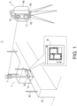
- FIG. 1 is an external schematic view of an unevenness level inspecting system (hereinafter, simply referred to as "system") S according to an embodiment of the present invention.
- the system S includes an unevenness level inspecting device 1 (hereinafter, simply referred to as “inspecting device”) and a surveying instrument 6.
- FIG. 1 illustrates a state where an unevenness level of a top end of a foundation rising 91 is inspected by using the system S.
- a reference sign 92 denotes an anchor bolt.
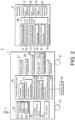
- FIG. 2 is a configuration block diagram of the system S.
- the system S is configured to inspect an unevenness level of a to-be-inspected surface by causing the inspecting device 1 that includes a target T and a traveling unit 21 including wheels, etc., to travel on the to-be-inspected surface by a manual operation.
- the inspecting device 1 has a housing 1a having a rectangular parallelepiped shape, and is configured to be capable of traveling on a traveling route by rotating bodies constituting the traveling unit 21.
- a pole 1b as a target support member is erected, and the target T is attached to an upper end portion of the pole 1b.
- the target T is a so-called all-around prism configured by radially combining a plurality of triangular pyramid-shaped prisms, and retro-reflects light incident from the entire circumference (360°).
- the inspecting device 1 includes the target T, a control arithmetic unit 10, the traveling unit 21, a hammering test unit 22, a traveling distance/speed sensor 25, a tilt sensor 26, a display unit 27, an operation unit 28, a communication unit 29, a storage unit 31, and an indicator 32.
- the traveling unit 21 is provided.
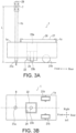
- the traveling unit 21 includes one front wheel 21a, and a pair of rear wheels 21b provided left and right to face each other.
- the front wheel 21a is a ball caster that can move in 360-degree directions by a bearing.
- the rear wheels 21b are wheels (rollers), and are respectively independently rotatable around rotation shafts provided orthogonal to a traveling direction when traveling straight forward.
- the housing 1a is adjusted so that its upper surface is level when the inspecting device 1 is placed on a level surface.
- the pole 1b is provided orthogonal to the upper surface of the housing 1a.
- the target T is attached just above the front wheel 21a.
- a worker pushes the housing 1a or the pole 1b of the inspecting device 1 by hand to cause the inspecting device 1 to travel forward and backward on a to-be-inspected surface by a manual operation so that the front wheel 21a continued to the pole 1b is always in contact with the to-be-inspected surface at a grounding point R.
- the hammering test unit 22 includes a hammering unit 23 including a solenoid coil 23a and a columnar hammer 23b, and a sound collecting unit 24.
- the hammering unit 23 hammers the to-be-inspected surface by moving the hammer 23b up and down repeatedly in a predetermined period according to ON/OFF of current application to the solenoid coil 23a.
- the sound collecting unit 24 is a so-called microphone, and collects hammering sounds issued by the hammer 23b and outputs them to the control arithmetic unit 10.
- the hammering test unit 22 is aligned with the pole 1b in the front-rear direction so as to prevent a size in a width direction of the inspecting device 1 from increasing.
- the traveling distance/speed sensor 25 includes a rotary encoder provided on, for example, the rear wheel 21b of the traveling unit 21, and detects a traveling distance of the inspecting device 1 from the number of rotations of the rear wheel 21b. In addition, the traveling distance/speed sensor 25 detects a speed from an angular velocity of rotation of the rear wheel 21b. Alternatively, the traveling distance/speed sensor 25 may be capable of detecting a traveling distance and speed by measuring its own position by using a GNSS device that can detect its own position based on a navigation signal of a navigation satellite. Alternatively, the traveling distance/speed sensor 25 may be capable of detecting a traveling distance and speed of the inspecting device based on position coordinates of the inspecting device obtained by a coordinate acquiring unit 11 described later.
- the tilt sensor 26 is, for example, an electronic tilt sensor, and is provided in relation to two axes of an X-axis direction (left-right direction of the device main body) and a Y-axis direction (front-rear direction of the device main body) inside the housing 1a or near the target T.
- the tilt sensor 26 detects a tilt of the target T at a timing synchronized with a timing of a measurement of the target T by the surveying instrument 6, and outputs a detection result to the control arithmetic unit 10.
- the display unit 27 is, for example, a liquid crystal display.
- the operation unit 28 is, for example, a keyboard, a mouse, etc., and enables a worker to perform various inputs, selections, instructions, and determinations, etc.
- the display unit 27 and the operation unit 28 are integrally configured as a touch panel display, and the display is attached as a detachable display to a holder 1c at an upper portion of the housing 1a. Without limitation to this, these units may be integrally configured on an outer surface of the housing 1a.
- the communication unit 29 enables wireless transmission and reception of information between the inspecting device 1 and the surveying instrument 6.
- a communication means Wi-Fi, Bluetooth (registered trademark), infrared communication, the Internet, a mobile phone network, etc., can be used.
- the storage unit 31 is a nonvolatile storage as an auxiliary storage device.
- the storage unit 31 is, for example, an HDD (Hard Disc Drive) or SSD (Solid State Drive) .
- the storage unit 31 may be partially configured by an external storage device such as a USB flash memory.
- the storage unit 31 stores at least programs for executing functions of the respective functional units of the control arithmetic unit 10 when the respective functional units are implemented software-wise.
- CAD design data 31a is stored in the storage unit 31, CAD (Computer Aided Design) design data 31a is stored.
- the CAD design data 31a is a design drawing of a work site, a construction object, a structure, etc., created by a computer such as a personal computer.
- the CAD design data 31a is created by using an absolute coordinate system such as a map coordinate system.
- the indicator 32 indicates that a worker is causing the inspecting device 1 to travel in an appropriate speed range based on detection results of the traveling distance/speed sensor 25.
- the indicator 32 includes, for example, an LED light source and a cover, and emits green light when the speed of the inspecting device 1 is within an appropriate range. A worker causes the inspecting device 1 to travel while confirming light emission of the indicator 32.
- the control arithmetic unit 10 is a control arithmetic unit that includes at least a CPU (Central Processing Unit) and a RAM (Random Access Memory) .
- the control arithmetic unit reads out various programs stored in the storage unit to the memory and executes them.
- the control arithmetic unit 10 includes, as functional units, the coordinate acquiring unit 11, an unevenness level information generating unit 12, a hammering test control unit 13, a hammering sound determining unit 14, and a display data generating/updating unit 15.
- the coordinate acquiring unit 11 acquires three-dimensional position coordinates of the target T (hereinafter, referred to as "target position coordinates") acquired by the surveying instrument 6 at predetermined intervals, and calculates three-dimensional position coordinates of the inspecting device 1 (hereinafter, referred to as "inspecting device position coordinates").
- the acquired coordinates are stored in the storage unit 31.
- Inspecting device position coordinates can be obtained from the acquired target position coordinates, a detection value of the tilt sensor 26, and a distance L (known) from the target T to the grounding point R.
- the unevenness level information generating unit 12 sets a reference height as a reference of unevenness level determination, and calculates a height component (z component) of inspecting device position coordinates acquired by the coordinate acquiring unit 11 from the inspecting device position coordinates, as a height of the to-be-inspected surface at a device position (unevenness level inspection position) corresponding to the measurement position of the target T.
- a reference height an arbitrary value can be input in advance by a worker. It is preferable that the foundation rising height at the site is measured at a plurality of points with a measuring tape, etc., before the start of the inspection. For example, a representative value such as an average value, a median value, or a mode value of the measurement results is set as a reference height.
- a height of a to-be-inspected surface at a starting point may be set as a reference height.
- the unevenness level information generating unit 12 generates unevenness level information associating a difference between the calculated to-be-inspected surface height and the reference height with inspecting device position coordinates, and outputs the unevenness level information to the display data generating/updating unit 15.
- the hammering test control unit 13 conducts a hammering test by controlling the hammering unit 23 and the sound collecting unit 24.
- the hammering sound determining unit 14 determines whether the to-be-inspected surface has an abnormality from a hammering sound difference, and when an abnormality is found, generates hammering sound determination results associating information on the presence of the abnormality with hammering position coordinates, and outputs the hammering sound determination results to the display data generating/updating unit 15.
- an abnormality means a crack, peeling, and floating, etc., of a to-be-inspected surface.
- a determination as to whether there is an abnormality is made based on differences in waveform and frequency between abnormal hammering sounds and normal hammering sounds.
- the hammering sound determining unit 14 may determine whether a to-be-inspected surface is normal or abnormal by using a learned model for determining normal/abnormal hammering sounds, the model obtained by performing machine learning by using learning data obtained by labeling normal and abnormal hammering sounds of various to-be-inspected surfaces.
- a learned model for determining normal/abnormal hammering sounds the model obtained by performing machine learning by using learning data obtained by labeling normal and abnormal hammering sounds of various to-be-inspected surfaces.
- normal hammering sounds are registered before the start of the inspection, and when a hammering sound deviating from the normal hammering sounds is detected, a determination as to whether the to-be-inspected surface is normal/abnormal is made.
- the display data generating/updating unit 15 reads out CAD design data 31a from the storage unit 31, and generates display data 50 for displaying unevenness level information input from the unevenness level information generating unit in a manner that the unevenness level information is superimposed on a drawing of the CAD design data 31a.
- the display data generating/updating unit adds hammering sound determination results input from the hammering sound determining unit 14 to the display data so that the hammering sound determination results are superimposed and displayed on the unevenness level information.
- the display data generating/updating unit 15 updates the display data 50 to reflect new unevenness level information and hammering sound determination results each time the unevenness level information and the hammering sound determination results are input.
- the functions of these functional units may be implemented hardware-wise in circuits and programmable logic devices, etc., or may be implemented software-wise by programs.
- these programs may be stored in a computer-readable storage medium such as a CD (Compact Disc), a DVD (Digital Versatile Disc), a Blu-ray (registered trademark) disc, and distributed.
- the surveying instrument 6 is a motor-driven total station having an automatic tracking function.
- the surveying instrument 6 includes, in appearance, a base portion 6a provided on a leveling device, a bracket portion 6b that rotates horizontally on the base portion 6a, a telescope 6c that rotates vertically at the center of the bracket portion 6b, and a display unit 77 and an operation unit 78 provided on a front surface of the bracket portion 6b.
- the surveying instrument 6 includes a control arithmetic unit 60, a distance-measuring unit 71, a horizontal angle detector 72, a vertical angle detector 73, a horizontal rotation driving unit 74, a vertical rotation driving unit 75, an automatic tracking unit 76, the display unit 77, the operation unit 78, a storage unit 79, and a communication unit 81.
- the distance-measuring unit 71 outputs distance-measuring light such as an infrared laser toward the target T, and receives reflected light to measure a distance to the target T.
- the horizontal angle detector 72 detects a rotation angle of the bracket portion 6b in the horizontal direction
- the vertical angle detector 73 detects a rotation angle of the telescope 6c in the vertical direction. Accordingly, an angle of an optical axis of the distance-measuring light, that is, an angle of the target T is measured.
- the horizontal rotation driving unit 74 and the vertical rotation driving unit 75 are motors that are controlled by the control arithmetic unit 60 and respectively drive a horizontal rotation shaft and a vertical rotation shaft.
- the automatic tracking unit 76 emits, as tracking light, an infrared laser, etc., of a wavelength different from that of the distance-measuring light and receives reflected light by an image sensor such as a CCD sensor or CMOS sensor, and acquires a landscape image including the tracking light and a landscape image excluding the tracking light.
- the control arithmetic unit 60 detects a position of the target T from a difference between these images, and performs automatic tracking so that the telescope 6c always faces the target T.
- the display unit 77 and the operation unit 78 are user interfaces of the surveying instrument 6. Via these units, command and setting of a surveying operation, and confirmation of an operation status and measurement results, etc. can be performed.
- the storage unit 79 consists of, for example, a memory card, an HDD, etc.
- the storage unit 79 stores various programs for realizing various functions including a distance-measuring program of the surveying instrument 6.
- the storage unit 79 stores various information acquired by the control arithmetic unit 60.
- the communication unit 81 enables wireless communication with the inspecting device 1 by using the same communication method.
- Target position coordinates calculated under the control of the control arithmetic unit 60 are transmitted to a controller 4 at predetermined intervals.
- the control arithmetic unit 60 is a control arithmetic unit configured by mounting at least a CPU and a memory on an integrated circuit, and controls the rotation driving units 74 and 75 and controls the distance-measuring unit 71 and the automatic tracking unit 76.
- the control arithmetic unit 60 calculates target position coordinates from distance and angle measurement results of the target T.
- the control arithmetic unit 60 automatically tracks the target T, and according to an instruction from the inspecting device 1, makes distance and angle measurements of the target T and transmits target position coordinates to the inspecting device at all times.
- the surveying instrument 6 is not limited to a total station, and a surveying device such as a scanner device having an automatic tracking function and a target scanning function can be applied as long as it can perform automatic tracking and acquire three-dimensional position coordinates of the target T.
- a surveying device such as a scanner device having an automatic tracking function and a target scanning function can be applied as long as it can perform automatic tracking and acquire three-dimensional position coordinates of the target T.
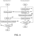
- Step S01 While performing automatic tracking in Step S01, the surveying instrument 6 makes distance and angle measurements of the target T in Step S02. Next, in Step S03, the surveying instrument 6 calculates target position coordinates, and in Step S04, transmits the target position coordinates to the inspecting device 1. In Step S05, until a worker instructs the completion through the inspecting device 1, Steps S01 to S05 are repeated.
- Step S06 When the inspecting device 1 starts an inspection according to a worker's instruction, in Step S06, the tilt sensor 26 outputs a detection value to the control arithmetic unit 10 at a timing synchronized with the distance and angle measurements of the target T made by the surveying instrument 6.
- Step S07 the inspecting device 1 receives target position coordinates from the surveying instrument 6, and in Step S08, the inspecting device 1 calculates inspecting device position coordinates.
- Step S09 until the worker instructs the completion, Steps S06 to S09 are repeated at all times.
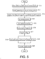
- FIG. 5 is a flowchart describing an outline of the work procedures of this entire inspecting method.
- a worker installs the surveying instrument 6 at an instrument point.
- the instrument point is a known point, or is known by measuring known points after installation of the surveying instrument 6.
- a direction angle of the surveying instrument 6 is known by measuring a plurality of known points.
- Three-dimensional position coordinates acquired in the surveying instrument 6 are converted into coordinates in the same absolute coordinate system as the CAD design data 31a.
- Step S12 the worker installs the inspecting device 1 at a starting point.
- Step S13 according to a worker's instruction, the surveying instrument 6 measures target position coordinates of the inspecting device 1 installed at the starting point, and accordingly, as in the basic operation, acquires inspecting device position coordinates.
- Step S14 as described later, the inspecting device 1 sets a reference height.
- Step S15 according to a worker's instruction, automatic tracking by the surveying instrument 6 is started.
- Step S16 when the inspecting device 1 and the surveying instrument 6 are instructed by the worker to start an inspection, the inspecting device 1 and the surveying instrument 6 start basic operations.
- Step S17 the worker starts traveling of the inspecting device 1 by pushing the inspecting device 1 by hand.
- Step S18 the inspecting device 1 conducts an unevenness level inspection, and at the same time, conducts a hammering test in Step S19.
- unevenness level inspection and the hammering test unevenness level information and hammering sound determination results are output at the respective predetermined intervals.
- Step S20 the inspecting device 1 generates display data from unevenness level information and the hammering sound determination results.
- the processes in Steps S18 and S19 are performed in parallel during traveling, and the process in Step S20 is performed in coordination with the processes in Steps S18 and S19.
- the generated display data 50 may be displayed on the display unit 27, or may be stored in the storage unit 31. Alternatively, the display data 50 may be output to an external device through the communication unit 29. After that, the inspection is completed.
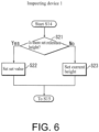
- Step S21 the unevenness level information generating unit 12 determines whether there is a reference height set in advance. In the case of Yes, the unevenness level information generating unit 12 sets the value as a reference height. In the case of No, a height of the to-be-inspected surface at the starting point is calculated from the inspecting device position coordinates acquired in Step S13, and this height is set as a reference height, and the processing shifts to Step S15.
- Step S31 the unevenness level information generating unit 12 determines whether the inspecting device 1 has traveled a predetermined distance (for example, 3 cm) based on output values of the traveling distance/speed sensor 25.
- Step S32 the unevenness level information generating unit 12 calculates a height of the to-be-inspected surface.
- Step S33 the unevenness level information generating unit 12 compares the calculated to-be-inspected surface height and the reference height.
- Step S34 unevenness level information associating a magnitude of a difference between the to-be-inspected surface height and the reference height with the inspecting device position coordinates is output to the display data generating/updating unit 15.
- Step S35 until an instruction to complete the inspection is given, Steps S31 to S35 are repeated.
- Step S41 the hammering test control unit 13 starts hammering with the hammer 23b by controlling the hammering unit 23, and starts hammering sound collection by controlling the sound collecting unit 24 in Step S42.
- the collected hammering sounds are associated with hammering position coordinates and successively output to the hammering sound determining unit 14.
- Step S43 the hammering sound determining unit 14 determines whether there is a hammering sound abnormality.
- the hammering sound determining unit 14 generates hammering sound determination results associating information on the presence of the abnormality with hammering position coordinates, and outputs the hammering sound determination results to the display data generating/updating unit 15.
- Step S45 until a command to complete the test is given, Steps S41 to S45 are repeated.
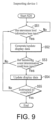
- Step S20 when Step S20 starts, and in Step S51, the unevenness level information output in Step S34 is input into the display data generating/updating unit 15 (in the case of Yes), in Step S52, the display data generating/updating unit 15 reads the CAD design data 31a from the storage unit 31 and generates display data.
- Step S53 when the hammering sound determination results output in Step S44 are input (in the case of Yes), in Step S54, the display data generating/updating unit 15 updates display data so that the hammering sound determination results are superimposed and displayed on the display data generated in Step S52. In Step S55, Steps S51 to S55 are repeated until the worker instructs the completion of the inspection.
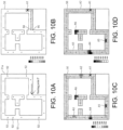
- FIGS. 10B to 10D illustrate examples of display data when the present inspecting method is performed by causing the inspecting device 1 to travel in an arrow direction from a starting point P at the site indicated by the CAD design data 31a illustrated in FIG. 10A .
- the reference sign 91 denotes a foundation rising.
- the reference sign 92 denotes an anchor bolt provided at a top end of the foundation rising.
- rectangular indications 95 centered at respective device positions (unevenness inspection position) 94 corresponding to respective target T measurement positions are assigned.
- a size of each rectangular indication 95 corresponds to a size having a length of 3 cm in a traveling direction ⁇ a width of 6 cm at the site in a case where a height of the to-be-inspected surface is calculated each time the inspecting device travels 3 cm. That is, a rectangular region with a width half the width of the to-be-inspected surface represents a measurement value of the device position.
- the display data generating/updating unit 15 superimposes and displays a rectangular indication 95 filled with a color that differs depending on a magnitude of a difference between a height of the to-be-inspected surface at the unevenness inspection position 94 and the reference height, on the CAD design data 31a.
- the colors to fill the rectangular indications 95 are not particularly limited. However, for example, as illustrated in FIGS. 10B and 10C , bi-polar color progression is preferably used.
- a difference from the reference height falling within a predetermined range ( ⁇ 1 mm, etc.) based on 0 mm as a reference, is filled with white or no color, and the filling color becomes darker as an absolute value of the difference increases toward the more positive and negative sides.
- single hue color progression is preferably used as illustrated in FIG. 10D .
- the filling color becomes darker as the difference from the reference height increases (from a negative value to a positive value) . Both color progressions enable intuitive recognition of the unevenness level.
- a difference from the reference height is represented by a positive value when the height of the to-be-inspected surface is higher than the reference height, and represented by a negative value when the height of the to-be-inspected surface is lower than the reference height.
- a reference height is set to a representative value such as an average value, a median value or a mode value of heights of the to-be-inspected surface measured at a plurality of points on the to-be-inspected surface, and bi-polar color progression indication is used so that a difference of 0 mm from the reference height is displayed in white or no color, and the color becomes darker as an absolute value of the difference increases toward the more positive and negative sides. Accordingly, only a portion that is not level, such as a depressed portion or a protruding portion, can be emphasized by being colored. As a result, an unevenness level can be more intuitively recognized.
- a reference height is set to a height of the to-be-inspected surface at the starting point P, and single hue color progression indication is used so that the filling color becomes darker according to a magnitude of the difference from the reference height.
- FIG. 10D it is not necessary to measure a height of the to-be-inspected surface in advance, and even when it is unknown what level the reference height is in the entire to-be-inspected surface, the unevenness level can be intuitively recognized.
- the display data generating/updating unit 15 updates the display data 50 so that an indication of the hammering sound determination results is superimposed and displayed on the CAD design data 31a (superimposed on the rectangular indications 95 indicating unevenness level information). In the illustrated example, a cross mark is displayed.
- FIG. 10B illustrates display data 50 when the inspecting device 1 is caused to travel from a starting point in FIG. 10A to a region A1.
- the display data 50 is updated. Therefore, by displaying the display data 50 on the display unit 27 and updating the display in real time, a worker can grasp the progress status of the inspection. As a result, overlapping and omission of inspection can be prevented.
- FIGS. 10C and 10D illustrate display data 50 when the inspection of the entire site is completed. From the display data 50, it is found that, at points A1 and A5, the to-be-inspected surface is level although it has an abnormality such as a crack. It is also found that, at points A2 and A3, the surface has a depression although it has no abnormality such as a crack. It is also found that, at point A4, although the surface has no abnormality, it protrudes, and at point A6, the to-be-inspected surface protrudes and has a surface abnormality.
- an unevenness level and a hammering inspection result of a to-be-inspected surface can be intuitively and visually recognized, so that even common people without expertise can easily recognize the accuracy of a top end and an abnormality of its upper surface.
- the top end leveler may crack or peel off by shrinking when dried due to its properties. Even when the top end leveler cracks or peels off, no problem occurs as long as the level surface is maintained. On the other hand, there are certain cases that cracking, etc., causes unevenness. Common people without expertise may have an unfavorable impression due to the extremely deteriorated finish by cracks. Therefore, a problem may occur between an owner of a construction object and a worker. In the present embodiment, the presence of cracking, peeling, etc., is indicated by a marking, and an unevenness level is indicated by a rectangle. For example, the worker can indicate that cracks are present at the points A1 and A5 but they pose no problem, and the owner, etc., concerned about cracking and peeling, etc., can be relieved.
- the inspecting device 1 may be configured to have two modes of an unevenness level inspection mode and a hammering test mode, and conduct only an unevenness level inspection or only a hammering test.
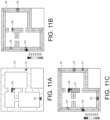
- FIG. 11A illustrates display data 50 when the same site as in FIG. 10C is inspected in the hammering test mode
- FIG. 11B illustrates display data 50 when the unevenness level inspection mode is executed. In this way, by performing an independent inspection as necessary, necessary data can be displayed.
- FIG. 11C illustrates a different example of display data 50.
- an uninspected region A7 is displayed in a color tone different from that of unevenness level information. Accordingly, an uninspected region can be emphasized, so that omission of inspection can be prevented.
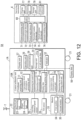
- FIG. 12 is a configuration block diagram of a system SA according to a second embodiment.
- FIG. 13A is a side view of an inspecting device 1A constituting the system SA, and
- FIG. 13B is a bottom view of the same.
- the system SA has a configuration substantially similar to the configuration of the system S except for the following respects.
- the inspecting device 1A further includes a marker 33.
- the marker 33 includes a first marker 34 and a second marker 35.
- the marker 33 is a jet-type ink discharging device that includes at least an ink tank, an actuation mechanism, and an ink discharge mechanism, and discharges ink in the form of a dot (small circle) toward a predetermined position.
- the first marker 34 is disposed at a rear side of the front wheel 21a and close to the front wheel 21a, and according to control of an unevenness level information printing control unit 16, marks unevenness level information at a position corresponding to a target measurement position.
- the second marker 35 is disposed at a rear side of the hammering test unit 22 and close to the hammering test unit 22, and according to control of a hammering sound determination result printing control unit 17, marks a hammering test result at a position corresponding to a hammering position.
- the first marker 34 is configured to be capable of discharging inks in a plurality of colors
- the second marker 35 is configured to be capable of discharging ink in a color different from the ink colors of the first marker 34.
- the first marker 34 and the second marker 35 are disposed so that their marking regions deviate from each other in a left-right direction orthogonal to a front-rear direction that is a traveling direction, and a marking region by the first marker 34 and a marking region by the second marker 35 do not overlap each other on the to-be-inspected surface even when they are at the same position in the traveling direction.
- a control arithmetic unit 10A further includes the unevenness level information printing control unit 16 and the hammering sound determination result printing control unit 17.
- the unevenness level information printing control unit 16 prints unevenness level information (marking M 1 ) corresponding to a determined unevenness level on a to-be-inspected surface by controlling the first marker 34.
- the hammering sound determination result printing control unit 17 prints hammering test results (marking M 2 ) on a to-be-inspected surface when the hammering sound determining unit 15 determines an abnormality.
- FIG. 14B illustrates an example of markings M 1 and M 2 printed on a to-be-inspected surface when a top end of the foundation rising 91 illustrated in FIG. 14A is inspected by causing the inspecting device to travel along an inspection route 93.
- a marking M 1 indicates an unevenness level inspection result
- a marking M 2 indicates a hammering test result.
- a plurality of anchor bolts 92 project vertically.
- a marking is displayed in a color that differs depending on a magnitude of a difference from the reference height.
- bi-polar color progression is used in a manner that a difference from the reference height, falling within a predetermined range ( ⁇ 1 mm, etc.) based on 0 mm as a reference, is displayed in white or provided with no mark, and the color becomes darker as an absolute value of the difference increases toward the more positive and negative sides .
- a height of the starting point is set as the reference height, and the level of the reference height is unknown in the entirety, it is preferable to use a single hue color progression.
- a difference from the reference height is represented by a positive value when the height of the to-be-inspected surface is higher than the reference height, and represented by a negative value when the height of the to-be-inspected surface is lower than the reference height.
- unevenness level information is indicated on a to-be-inspected surface at the site according to a magnitude of a difference between a current height and a reference height, so that the state of the site can be visually grasped at the site through one inspection, and it becomes possible to explain the state to a client and acquire digital data to be used for recording, etc.
- FIG. 14C illustrates an example of a to-be-inspected surface on which markings of hammering test results are printed in addition to the markings indicating unevenness level information.
- Hammering test results are indicated by yellow, etc., that are marks different from the types of the colors of the unevenness level information.
- a marking in a fluorescent color may be marked.
- hammering test results of the upper surface state can be easily visually recognized at the site.
Landscapes
- Physics & Mathematics (AREA)
- General Physics & Mathematics (AREA)
- Radar, Positioning & Navigation (AREA)
- Engineering & Computer Science (AREA)
- Remote Sensing (AREA)
- Immunology (AREA)
- Biochemistry (AREA)
- General Health & Medical Sciences (AREA)
- Health & Medical Sciences (AREA)
- Life Sciences & Earth Sciences (AREA)
- Pathology (AREA)
- Analytical Chemistry (AREA)
- Acoustics & Sound (AREA)
- Chemical & Material Sciences (AREA)
- Length Measuring Devices By Optical Means (AREA)
- Position Input By Displaying (AREA)
- On-Site Construction Work That Accompanies The Preparation And Application Of Concrete (AREA)
Abstract
Description
- The present disclosure relates to an unevenness level inspecting device and an unevenness level inspecting method, more specifically, to an unevenness level inspecting device, an unevenness level inspecting method, and a program for inspecting the levelness accuracy of an upper surface of a structure.
- During a construction work, normally, a foundation work is performed in which a foundation serving as a base structure of a building is constructed. A rising top end of the foundation is required to have a level upper surface. That is, to eliminate level differences of the top end as much as possible. This is because, in actuality, the levelness accuracy of the building depends on the top end accuracy. In this description, a "top end" means a portion that is an uppermost surface of an arbitrary structure regardless of a foundation rising.
- Therefore, after placement of concrete at the foundation rising, a self-leveling material called a top end leveler is poured into a formwork about several millimeters to 1 centimeter to level an upper surface of the top end. The top end leveler is mortar adjusted to be lower in viscosity than ready mix concrete, and when the top end leveler is poured into the formwork, it spreads evenly and brings about a level finish.
- However, in actuality, it is difficult to obtain perfect levelness. While a low portion needs additional application, a high portion needs to be scraped off. The top end accuracy during work is confirmed by a worker by measurement with a measuring tape, and this operation is complicated.
- Patent Literature 1:
Japanese Published Unexamined Patent Application No. 2021-11772 -
Patent Literature 1 discloses an unevenness level inspecting device which includes a traveling mechanism, a target, and a control unit, and can travel to a desired position while performing tracking by a surveying instrument (total station) having an automatic tracking function, measure an unevenness level of a floor surface from measurement results of the target, and output unevenness level information to an external device. - It is disclosed that, in the unevenness level inspecting device of
Patent Literature 1, unevenness level information is, for example, a numerical value of height adjusting amounts of facilities and equipment to be installed on a floor surface. Such information related to the numerical value is necessary and sufficient for a worker at a site. However, for an explanation, etc., to a client without expertise, it has been required to output unevenness level inspection results at the entire site in the form of unevenness level display data that is intuitively and visually recognizable. - The present invention was made in view of these circumstances, and an object thereof is to provide an unevenness level inspecting device and an unevenness level inspecting method by which intuitively and visually recognizable unevenness level display data is output.
- In order to achieve the object described above, an unevenness level inspecting device according to an aspect of the present invention includes a target at a known distance from a to-be-inspected surface, a traveling unit for traveling on the to-be-inspected surface, a communication unit capable of making communication with a surveying instrument configured to measure three-dimensional position coordinates of the target at predetermined intervals, and a control unit configured to calculate a height of the to-be-inspected surface corresponding to a measurement position of the target based on the three-dimensional position coordinates of the target, wherein the control unit calculates a height of the to-be-inspected surface corresponding to a measurement position of the target measured each time the unevenness level inspecting device travels a predetermined distance based on the three-dimensional position coordinates of the target, and generates display data for displaying unevenness level information associating a difference between the height of the to-be-inspected surface and a reference height with inspecting device position coordinates in a manner that the unevenness level information is superimposed on a site design drawing.
- An unevenness level inspecting method according to another aspect of the present invention is an unevenness level inspecting method using an unevenness level inspecting device including a target at a known distance from a to-be-inspected surface, a traveling unit for traveling on the to-be-inspected surface, a communication unit capable of making communication with a surveying instrument configured to measure three-dimensional position coordinates of the target at predetermined intervals, and a control unit configured to calculate a height of the to-be-inspected surface corresponding to a measurement position of the target based on the three-dimensional position coordinates of the target, wherein the control unit calculates a height of the to-be-inspected surface at a measurement position of the target measured each time the unevenness level inspecting device travels a predetermined distance based on the three-dimensional position coordinates of the target, and generates display data for displaying unevenness level information associating a difference between the height of the to-be-inspected surface and a reference height with inspecting device position coordinates in a manner that the unevenness level information is superimposed on a site design drawing.
- A program according to still another embodiment of the present invention causes a computer to perform the unevenness level inspecting method according to the aspect described above.
- According to the unevenness level inspecting device and the unevenness level inspecting method according to the aspects described above, unevenness level inspection results can be output as intuitively and visually recognizable unevenness level display data.
-
-
FIG. 1 is a view illustrating an outline of an unevenness level inspecting system according to an embodiment of the present invention. -
FIG. 2 is a configuration block diagram of the same inspecting system. -
FIG. 3A is a side view of an unevenness level inspecting device constituting the same inspecting system, andFIG. 3B is a bottom view of the same. -
FIG. 4 is a process flowchart of basic operations of the inspecting device and a surveying instrument in the same inspecting system. -
FIG. 5 is a flowchart describing the entirety of an unevenness level inspecting method using the same inspecting system. -
FIG. 6 is a process flowchart related to settings of a reference height for an unevenness level inspection in the same inspecting method. -
FIG. 7 is a process flowchart related to an unevenness level inspection in the same inspecting method. -
FIG. 8 is a process flowchart related to a hammering test in the same inspecting method. -
FIG. 9 is a process flowchart related to display data generation in the same inspecting method. -
FIGS. 10A, 10B, 10C, and 10D are views illustrating examples of display data that are generated by the same inspecting device. -
FIGS. 11A, 11B, and 11C are views illustrating different examples of display data that are generated by the same inspecting device. -
FIG. 12 is a configuration block diagram of an inspecting system according to a second embodiment of the present invention. -
FIG. 13A is a side view of an unevenness level inspecting device constituting the same inspecting system, andFIG. 13B is a bottom view of the same. -
FIGS. 14A, 14B, and 14C are views illustrating examples of markings printed on a to-be-inspected surface by an unevenness level inspecting method using the same inspecting system. - Hereinafter, preferred embodiments of the present invention will be described with reference to the drawings, however, the present invention is not limited to these. Components having the same function common to the respective embodiments and modifications are provided with the same name, and the same components are provided with the same reference signs, and overlapping description will be omitted as appropriate.
-
FIG. 1 is an external schematic view of an unevenness level inspecting system (hereinafter, simply referred to as "system") S according to an embodiment of the present invention. The system S includes an unevenness level inspecting device 1 (hereinafter, simply referred to as "inspecting device") and asurveying instrument 6.FIG. 1 illustrates a state where an unevenness level of a top end of a foundation rising 91 is inspected by using the system S.A reference sign 92 denotes an anchor bolt.FIG. 2 is a configuration block diagram of the system S. - The system S is configured to inspect an unevenness level of a to-be-inspected surface by causing the inspecting
device 1 that includes a target T and a travelingunit 21 including wheels, etc., to travel on the to-be-inspected surface by a manual operation. - The inspecting
device 1 has ahousing 1a having a rectangular parallelepiped shape, and is configured to be capable of traveling on a traveling route by rotating bodies constituting thetraveling unit 21. - On an upper surface of the
housing 1a, apole 1b as a target support member is erected, and the target T is attached to an upper end portion of thepole 1b. The target T is a so-called all-around prism configured by radially combining a plurality of triangular pyramid-shaped prisms, and retro-reflects light incident from the entire circumference (360°). - The
inspecting device 1 includes the target T, a controlarithmetic unit 10, thetraveling unit 21, ahammering test unit 22, a traveling distance/speed sensor 25, atilt sensor 26, adisplay unit 27, anoperation unit 28, acommunication unit 29, astorage unit 31, and anindicator 32. - At a lower portion of the
housing 1a, the travelingunit 21 is provided. In the example illustrated inFIGS. 3A, 3B , the travelingunit 21 includes onefront wheel 21a, and a pair ofrear wheels 21b provided left and right to face each other. Thefront wheel 21a is a ball caster that can move in 360-degree directions by a bearing. Therear wheels 21b are wheels (rollers), and are respectively independently rotatable around rotation shafts provided orthogonal to a traveling direction when traveling straight forward. - The
housing 1a is adjusted so that its upper surface is level when the inspectingdevice 1 is placed on a level surface. Thepole 1b is provided orthogonal to the upper surface of thehousing 1a. The target T is attached just above thefront wheel 21a. A worker pushes thehousing 1a or thepole 1b of the inspectingdevice 1 by hand to cause the inspectingdevice 1 to travel forward and backward on a to-be-inspected surface by a manual operation so that thefront wheel 21a continued to thepole 1b is always in contact with the to-be-inspected surface at a grounding point R. - The
hammering test unit 22 includes ahammering unit 23 including asolenoid coil 23a and acolumnar hammer 23b, and asound collecting unit 24. Thehammering unit 23 hammers the to-be-inspected surface by moving thehammer 23b up and down repeatedly in a predetermined period according to ON/OFF of current application to thesolenoid coil 23a. Thesound collecting unit 24 is a so-called microphone, and collects hammering sounds issued by thehammer 23b and outputs them to the controlarithmetic unit 10. Thehammering test unit 22 is aligned with thepole 1b in the front-rear direction so as to prevent a size in a width direction of the inspectingdevice 1 from increasing. - Position relationships of the target T with the grounding point R of the
front wheel 21a just below the target T and a hammering test position of the hammering test unit 22 (hammering point by thehammer 23b) are known. - The traveling distance/
speed sensor 25 includes a rotary encoder provided on, for example, therear wheel 21b of the travelingunit 21, and detects a traveling distance of the inspectingdevice 1 from the number of rotations of therear wheel 21b. In addition, the traveling distance/speed sensor 25 detects a speed from an angular velocity of rotation of therear wheel 21b. Alternatively, the traveling distance/speed sensor 25 may be capable of detecting a traveling distance and speed by measuring its own position by using a GNSS device that can detect its own position based on a navigation signal of a navigation satellite. Alternatively, the traveling distance/speed sensor 25 may be capable of detecting a traveling distance and speed of the inspecting device based on position coordinates of the inspecting device obtained by a coordinate acquiringunit 11 described later. - The
tilt sensor 26 is, for example, an electronic tilt sensor, and is provided in relation to two axes of an X-axis direction (left-right direction of the device main body) and a Y-axis direction (front-rear direction of the device main body) inside thehousing 1a or near the target T. Thetilt sensor 26 detects a tilt of the target T at a timing synchronized with a timing of a measurement of the target T by the surveyinginstrument 6, and outputs a detection result to the controlarithmetic unit 10. - The
display unit 27 is, for example, a liquid crystal display. Theoperation unit 28 is, for example, a keyboard, a mouse, etc., and enables a worker to perform various inputs, selections, instructions, and determinations, etc. In the illustrated example, thedisplay unit 27 and theoperation unit 28 are integrally configured as a touch panel display, and the display is attached as a detachable display to aholder 1c at an upper portion of thehousing 1a. Without limitation to this, these units may be integrally configured on an outer surface of thehousing 1a. - The
communication unit 29 enables wireless transmission and reception of information between the inspectingdevice 1 and the surveyinginstrument 6. As a communication means, Wi-Fi, Bluetooth (registered trademark), infrared communication, the Internet, a mobile phone network, etc., can be used. - The
storage unit 31 is a nonvolatile storage as an auxiliary storage device. Thestorage unit 31 is, for example, an HDD (Hard Disc Drive) or SSD (Solid State Drive) . Thestorage unit 31 may be partially configured by an external storage device such as a USB flash memory. Thestorage unit 31 stores at least programs for executing functions of the respective functional units of the controlarithmetic unit 10 when the respective functional units are implemented software-wise. - In addition, in the
storage unit 31, CAD (Computer Aided Design)design data 31a is stored. TheCAD design data 31a is a design drawing of a work site, a construction object, a structure, etc., created by a computer such as a personal computer. TheCAD design data 31a is created by using an absolute coordinate system such as a map coordinate system. - The
indicator 32 indicates that a worker is causing the inspectingdevice 1 to travel in an appropriate speed range based on detection results of the traveling distance/speed sensor 25. Theindicator 32 includes, for example, an LED light source and a cover, and emits green light when the speed of the inspectingdevice 1 is within an appropriate range. A worker causes the inspectingdevice 1 to travel while confirming light emission of theindicator 32. - The control
arithmetic unit 10 is a control arithmetic unit that includes at least a CPU (Central Processing Unit) and a RAM (Random Access Memory) . The control arithmetic unit reads out various programs stored in the storage unit to the memory and executes them. The controlarithmetic unit 10 includes, as functional units, the coordinate acquiringunit 11, an unevenness levelinformation generating unit 12, a hammeringtest control unit 13, a hammeringsound determining unit 14, and a display data generating/updatingunit 15. - As a basic operation of the inspecting
device 1, the coordinate acquiringunit 11 acquires three-dimensional position coordinates of the target T (hereinafter, referred to as "target position coordinates") acquired by the surveyinginstrument 6 at predetermined intervals, and calculates three-dimensional position coordinates of the inspecting device 1 (hereinafter, referred to as "inspecting device position coordinates"). The acquired coordinates are stored in thestorage unit 31. Inspecting device position coordinates can be obtained from the acquired target position coordinates, a detection value of thetilt sensor 26, and a distance L (known) from the target T to the grounding point R. - The unevenness level
information generating unit 12 sets a reference height as a reference of unevenness level determination, and calculates a height component (z component) of inspecting device position coordinates acquired by the coordinate acquiringunit 11 from the inspecting device position coordinates, as a height of the to-be-inspected surface at a device position (unevenness level inspection position) corresponding to the measurement position of the target T. As a reference height, an arbitrary value can be input in advance by a worker. It is preferable that the foundation rising height at the site is measured at a plurality of points with a measuring tape, etc., before the start of the inspection. For example, a representative value such as an average value, a median value, or a mode value of the measurement results is set as a reference height. When the reference height is not set in advance, a height of a to-be-inspected surface at a starting point may be set as a reference height. The unevenness levelinformation generating unit 12 generates unevenness level information associating a difference between the calculated to-be-inspected surface height and the reference height with inspecting device position coordinates, and outputs the unevenness level information to the display data generating/updatingunit 15. - The hammering
test control unit 13 conducts a hammering test by controlling thehammering unit 23 and thesound collecting unit 24. - The hammering
sound determining unit 14 determines whether the to-be-inspected surface has an abnormality from a hammering sound difference, and when an abnormality is found, generates hammering sound determination results associating information on the presence of the abnormality with hammering position coordinates, and outputs the hammering sound determination results to the display data generating/updatingunit 15. Here, an abnormality means a crack, peeling, and floating, etc., of a to-be-inspected surface. A determination as to whether there is an abnormality is made based on differences in waveform and frequency between abnormal hammering sounds and normal hammering sounds. - The hammering
sound determining unit 14 may determine whether a to-be-inspected surface is normal or abnormal by using a learned model for determining normal/abnormal hammering sounds, the model obtained by performing machine learning by using learning data obtained by labeling normal and abnormal hammering sounds of various to-be-inspected surfaces. Alternatively, at the site, normal hammering sounds are registered before the start of the inspection, and when a hammering sound deviating from the normal hammering sounds is detected, a determination as to whether the to-be-inspected surface is normal/abnormal is made. - The display data generating/updating
unit 15 reads outCAD design data 31a from thestorage unit 31, and generatesdisplay data 50 for displaying unevenness level information input from the unevenness level information generating unit in a manner that the unevenness level information is superimposed on a drawing of theCAD design data 31a. In addition, the display data generating/updating unit adds hammering sound determination results input from the hammeringsound determining unit 14 to the display data so that the hammering sound determination results are superimposed and displayed on the unevenness level information. In addition, the display data generating/updatingunit 15 updates thedisplay data 50 to reflect new unevenness level information and hammering sound determination results each time the unevenness level information and the hammering sound determination results are input. - The functions of these functional units may be implemented hardware-wise in circuits and programmable logic devices, etc., or may be implemented software-wise by programs. When the functions are implemented by programs, these programs may be stored in a computer-readable storage medium such as a CD (Compact Disc), a DVD (Digital Versatile Disc), a Blu-ray (registered trademark) disc, and distributed.
- The surveying
instrument 6 is a motor-driven total station having an automatic tracking function. The surveyinginstrument 6 includes, in appearance, abase portion 6a provided on a leveling device, abracket portion 6b that rotates horizontally on thebase portion 6a, atelescope 6c that rotates vertically at the center of thebracket portion 6b, and adisplay unit 77 and anoperation unit 78 provided on a front surface of thebracket portion 6b. - The surveying
instrument 6 includes a controlarithmetic unit 60, a distance-measuringunit 71, ahorizontal angle detector 72, avertical angle detector 73, a horizontalrotation driving unit 74, a verticalrotation driving unit 75, anautomatic tracking unit 76, thedisplay unit 77, theoperation unit 78, astorage unit 79, and acommunication unit 81. - The distance-measuring
unit 71 outputs distance-measuring light such as an infrared laser toward the target T, and receives reflected light to measure a distance to the target T. - The
horizontal angle detector 72 detects a rotation angle of thebracket portion 6b in the horizontal direction, and thevertical angle detector 73 detects a rotation angle of thetelescope 6c in the vertical direction. Accordingly, an angle of an optical axis of the distance-measuring light, that is, an angle of the target T is measured. The horizontalrotation driving unit 74 and the verticalrotation driving unit 75 are motors that are controlled by the controlarithmetic unit 60 and respectively drive a horizontal rotation shaft and a vertical rotation shaft. - The
automatic tracking unit 76 emits, as tracking light, an infrared laser, etc., of a wavelength different from that of the distance-measuring light and receives reflected light by an image sensor such as a CCD sensor or CMOS sensor, and acquires a landscape image including the tracking light and a landscape image excluding the tracking light. The controlarithmetic unit 60 detects a position of the target T from a difference between these images, and performs automatic tracking so that thetelescope 6c always faces the target T. - The
display unit 77 and theoperation unit 78 are user interfaces of the surveyinginstrument 6. Via these units, command and setting of a surveying operation, and confirmation of an operation status and measurement results, etc. can be performed. - The
storage unit 79 consists of, for example, a memory card, an HDD, etc. Thestorage unit 79 stores various programs for realizing various functions including a distance-measuring program of the surveyinginstrument 6. In addition, thestorage unit 79 stores various information acquired by the controlarithmetic unit 60. - The
communication unit 81 enables wireless communication with the inspectingdevice 1 by using the same communication method. Target position coordinates calculated under the control of the controlarithmetic unit 60 are transmitted to acontroller 4 at predetermined intervals. - The control
arithmetic unit 60 is a control arithmetic unit configured by mounting at least a CPU and a memory on an integrated circuit, and controls therotation driving units unit 71 and theautomatic tracking unit 76. The controlarithmetic unit 60 calculates target position coordinates from distance and angle measurement results of the target T. The controlarithmetic unit 60 automatically tracks the target T, and according to an instruction from the inspectingdevice 1, makes distance and angle measurements of the target T and transmits target position coordinates to the inspecting device at all times. - The surveying
instrument 6 is not limited to a total station, and a surveying device such as a scanner device having an automatic tracking function and a target scanning function can be applied as long as it can perform automatic tracking and acquire three-dimensional position coordinates of the target T. - Next, an inspecting method using the system S will be described. First, basic operation of the system S will be described. As basic operation, the system S executes processing illustrated in
FIG. 4 during an inspection. - While performing automatic tracking in Step S01, the surveying
instrument 6 makes distance and angle measurements of the target T in Step S02. Next, in Step S03, the surveyinginstrument 6 calculates target position coordinates, and in Step S04, transmits the target position coordinates to the inspectingdevice 1. In Step S05, until a worker instructs the completion through the inspectingdevice 1, Steps S01 to S05 are repeated. - When the inspecting
device 1 starts an inspection according to a worker's instruction, in Step S06, thetilt sensor 26 outputs a detection value to the controlarithmetic unit 10 at a timing synchronized with the distance and angle measurements of the target T made by the surveyinginstrument 6. In Step S07, the inspectingdevice 1 receives target position coordinates from the surveyinginstrument 6, and in Step S08, the inspectingdevice 1 calculates inspecting device position coordinates. In Step S09, until the worker instructs the completion, Steps S06 to S09 are repeated at all times. -
FIG. 5 is a flowchart describing an outline of the work procedures of this entire inspecting method. When starting an inspection, in Step S11, a worker installs the surveyinginstrument 6 at an instrument point. The instrument point is a known point, or is known by measuring known points after installation of the surveyinginstrument 6. A direction angle of the surveyinginstrument 6 is known by measuring a plurality of known points. Three-dimensional position coordinates acquired in thesurveying instrument 6 are converted into coordinates in the same absolute coordinate system as theCAD design data 31a. - Next, in Step S12, the worker installs the inspecting
device 1 at a starting point. Next, in Step S13, according to a worker's instruction, the surveyinginstrument 6 measures target position coordinates of the inspectingdevice 1 installed at the starting point, and accordingly, as in the basic operation, acquires inspecting device position coordinates. Next, in Step S14, as described later, the inspectingdevice 1 sets a reference height. - Next, in Step S15, according to a worker's instruction, automatic tracking by the surveying
instrument 6 is started. Next, in Step S16, when the inspectingdevice 1 and the surveyinginstrument 6 are instructed by the worker to start an inspection, the inspectingdevice 1 and the surveyinginstrument 6 start basic operations. - In Step S17, the worker starts traveling of the inspecting
device 1 by pushing the inspectingdevice 1 by hand. When traveling is started, in Step S18, the inspectingdevice 1 conducts an unevenness level inspection, and at the same time, conducts a hammering test in Step S19. In the unevenness level inspection and the hammering test, unevenness level information and hammering sound determination results are output at the respective predetermined intervals. - In Step S20, the inspecting
device 1 generates display data from unevenness level information and the hammering sound determination results. The processes in Steps S18 and S19 are performed in parallel during traveling, and the process in Step S20 is performed in coordination with the processes in Steps S18 and S19. The generateddisplay data 50 may be displayed on thedisplay unit 27, or may be stored in thestorage unit 31. Alternatively, thedisplay data 50 may be output to an external device through thecommunication unit 29. After that, the inspection is completed. - Detailed processes in S14 and S18 to S20 will be respectively described with reference to
FIGS. 6 to 9 . - As illustrated in
FIG. 6 , when Step S14 starts, in Step S21, the unevenness levelinformation generating unit 12 determines whether there is a reference height set in advance. In the case of Yes, the unevenness levelinformation generating unit 12 sets the value as a reference height. In the case of No, a height of the to-be-inspected surface at the starting point is calculated from the inspecting device position coordinates acquired in Step S13, and this height is set as a reference height, and the processing shifts to Step S15. - As illustrated in
FIG. 7 , when Step S18 starts, in Step S31, the unevenness levelinformation generating unit 12 determines whether the inspectingdevice 1 has traveled a predetermined distance (for example, 3 cm) based on output values of the traveling distance/speed sensor 25. When the inspectingdevice 1 has traveled the predetermined distance (Yes), in Step S32, the unevenness levelinformation generating unit 12 calculates a height of the to-be-inspected surface. - Next, in Step S33, the unevenness level
information generating unit 12 compares the calculated to-be-inspected surface height and the reference height. Next, in Step S34, unevenness level information associating a magnitude of a difference between the to-be-inspected surface height and the reference height with the inspecting device position coordinates is output to the display data generating/updatingunit 15. In Step S35, until an instruction to complete the inspection is given, Steps S31 to S35 are repeated. - As illustrated in
FIG. 8 , when Step S19 starts, in Step S41, the hammeringtest control unit 13 starts hammering with thehammer 23b by controlling thehammering unit 23, and starts hammering sound collection by controlling thesound collecting unit 24 in Step S42. The collected hammering sounds are associated with hammering position coordinates and successively output to the hammeringsound determining unit 14. - In Step S43, the hammering
sound determining unit 14 determines whether there is a hammering sound abnormality. When an abnormality is found (Yes), in Step S44, the hammeringsound determining unit 14 generates hammering sound determination results associating information on the presence of the abnormality with hammering position coordinates, and outputs the hammering sound determination results to the display data generating/updatingunit 15. In Step S45, until a command to complete the test is given, Steps S41 to S45 are repeated. - As illustrated in
FIG. 9 , when Step S20 starts, and in Step S51, the unevenness level information output in Step S34 is input into the display data generating/updating unit 15 (in the case of Yes), in Step S52, the display data generating/updatingunit 15 reads theCAD design data 31a from thestorage unit 31 and generates display data. - Next, in Step S53, when the hammering sound determination results output in Step S44 are input (in the case of Yes), in Step S54, the display data generating/updating
unit 15 updates display data so that the hammering sound determination results are superimposed and displayed on the display data generated in Step S52. In Step S55, Steps S51 to S55 are repeated until the worker instructs the completion of the inspection. - Here, display data will be described.
FIGS. 10B to 10D illustrate examples of display data when the present inspecting method is performed by causing the inspectingdevice 1 to travel in an arrow direction from a starting point P at the site indicated by theCAD design data 31a illustrated inFIG. 10A . Thereference sign 91 denotes a foundation rising. Thereference sign 92 denotes an anchor bolt provided at a top end of the foundation rising. In thedisplay data 50,rectangular indications 95 centered at respective device positions (unevenness inspection position) 94 corresponding to respective target T measurement positions are assigned. For example, with respect to a foundation rising with a width of 12 cm, a size of eachrectangular indication 95 corresponds to a size having a length of 3 cm in a traveling direction × a width of 6 cm at the site in a case where a height of the to-be-inspected surface is calculated each time the inspecting device travels 3 cm. That is, a rectangular region with a width half the width of the to-be-inspected surface represents a measurement value of the device position. - Each time unevenness level information is input, the display data generating/updating
unit 15 superimposes and displays arectangular indication 95 filled with a color that differs depending on a magnitude of a difference between a height of the to-be-inspected surface at theunevenness inspection position 94 and the reference height, on theCAD design data 31a. The colors to fill therectangular indications 95 are not particularly limited. However, for example, as illustrated inFIGS. 10B and 10C , bi-polar color progression is preferably used. In this case, a difference from the reference height, falling within a predetermined range (± 1 mm, etc.) based on 0 mm as a reference, is filled with white or no color, and the filling color becomes darker as an absolute value of the difference increases toward the more positive and negative sides. Alternatively, single hue color progression is preferably used as illustrated inFIG. 10D . In this case, the filling color becomes darker as the difference from the reference height increases (from a negative value to a positive value) . Both color progressions enable intuitive recognition of the unevenness level. In this example, a difference from the reference height is represented by a positive value when the height of the to-be-inspected surface is higher than the reference height, and represented by a negative value when the height of the to-be-inspected surface is lower than the reference height. - In
FIGS. 10B and 10C , a reference height is set to a representative value such as an average value, a median value or a mode value of heights of the to-be-inspected surface measured at a plurality of points on the to-be-inspected surface, and bi-polar color progression indication is used so that a difference of 0 mm from the reference height is displayed in white or no color, and the color becomes darker as an absolute value of the difference increases toward the more positive and negative sides. Accordingly, only a portion that is not level, such as a depressed portion or a protruding portion, can be emphasized by being colored. As a result, an unevenness level can be more intuitively recognized. - On the other hand, in
FIG. 10D , a reference height is set to a height of the to-be-inspected surface at the starting point P, and single hue color progression indication is used so that the filling color becomes darker according to a magnitude of the difference from the reference height. In this case, it is not necessary to measure a height of the to-be-inspected surface in advance, and even when it is unknown what level the reference height is in the entire to-be-inspected surface, the unevenness level can be intuitively recognized. In the case ofFIG. 10D , it is also possible that after the inspection of the entire to-be-inspected surface is completed, a to-be-inspected surface height at a portion without unevenness is re-calculated and set as a new reference height, and the indication can be converted into bi-polar color progression indication according to a magnitude of a difference between the new reference height and a to-be-inspected surface height. - Each time hammering sound determination results are generated and input, the display data generating/updating
unit 15 updates thedisplay data 50 so that an indication of the hammering sound determination results is superimposed and displayed on theCAD design data 31a (superimposed on therectangular indications 95 indicating unevenness level information). In the illustrated example, a cross mark is displayed. -
FIG. 10B illustratesdisplay data 50 when the inspectingdevice 1 is caused to travel from a starting point inFIG. 10A to a region A1. As described above, each time unevenness level information and hammering sound determination results are input into the display data generating/updatingunit 15, thedisplay data 50 is updated. Therefore, by displaying thedisplay data 50 on thedisplay unit 27 and updating the display in real time, a worker can grasp the progress status of the inspection. As a result, overlapping and omission of inspection can be prevented. -
FIGS. 10C and 10D illustratedisplay data 50 when the inspection of the entire site is completed. From thedisplay data 50, it is found that, at points A1 and A5, the to-be-inspected surface is level although it has an abnormality such as a crack. It is also found that, at points A2 and A3, the surface has a depression although it has no abnormality such as a crack. It is also found that, at point A4, although the surface has no abnormality, it protrudes, and at point A6, the to-be-inspected surface protrudes and has a surface abnormality. In this way, according to the present embodiment, an unevenness level and a hammering inspection result of a to-be-inspected surface can be intuitively and visually recognized, so that even common people without expertise can easily recognize the accuracy of a top end and an abnormality of its upper surface. - The top end leveler may crack or peel off by shrinking when dried due to its properties. Even when the top end leveler cracks or peels off, no problem occurs as long as the level surface is maintained. On the other hand, there are certain cases that cracking, etc., causes unevenness. Common people without expertise may have an unfavorable impression due to the extremely deteriorated finish by cracks. Therefore, a problem may occur between an owner of a construction object and a worker. In the present embodiment, the presence of cracking, peeling, etc., is indicated by a marking, and an unevenness level is indicated by a rectangle. For example, the worker can indicate that cracks are present at the points A1 and A5 but they pose no problem, and the owner, etc., concerned about cracking and peeling, etc., can be relieved.
- The description given above is on the assumption that an unevenness level inspection and a hammering test are simultaneously conducted. Without limitation to this, the inspecting
device 1 may be configured to have two modes of an unevenness level inspection mode and a hammering test mode, and conduct only an unevenness level inspection or only a hammering test. In the case where the hammering test mode is executed,FIG. 11A illustratesdisplay data 50 when the same site as inFIG. 10C is inspected in the hammering test mode, andFIG. 11B illustratesdisplay data 50 when the unevenness level inspection mode is executed. In this way, by performing an independent inspection as necessary, necessary data can be displayed. -
FIG. 11C illustrates a different example ofdisplay data 50. InFIG. 11C , an uninspected region A7 is displayed in a color tone different from that of unevenness level information. Accordingly, an uninspected region can be emphasized, so that omission of inspection can be prevented. -
FIG. 12 is a configuration block diagram of a system SA according to a second embodiment.FIG. 13A is a side view of an inspectingdevice 1A constituting the system SA, andFIG. 13B is a bottom view of the same. The system SA has a configuration substantially similar to the configuration of the system S except for the following respects. - The inspecting
device 1A further includes amarker 33. Themarker 33 includes afirst marker 34 and asecond marker 35. Themarker 33 is a jet-type ink discharging device that includes at least an ink tank, an actuation mechanism, and an ink discharge mechanism, and discharges ink in the form of a dot (small circle) toward a predetermined position. Thefirst marker 34 is disposed at a rear side of thefront wheel 21a and close to thefront wheel 21a, and according to control of an unevenness level informationprinting control unit 16, marks unevenness level information at a position corresponding to a target measurement position. Thesecond marker 35 is disposed at a rear side of thehammering test unit 22 and close to thehammering test unit 22, and according to control of a hammering sound determination resultprinting control unit 17, marks a hammering test result at a position corresponding to a hammering position. Thefirst marker 34 is configured to be capable of discharging inks in a plurality of colors, and thesecond marker 35 is configured to be capable of discharging ink in a color different from the ink colors of thefirst marker 34. - The
first marker 34 and thesecond marker 35 are disposed so that their marking regions deviate from each other in a left-right direction orthogonal to a front-rear direction that is a traveling direction, and a marking region by thefirst marker 34 and a marking region by thesecond marker 35 do not overlap each other on the to-be-inspected surface even when they are at the same position in the traveling direction. - A control
arithmetic unit 10A further includes the unevenness level informationprinting control unit 16 and the hammering sound determination resultprinting control unit 17. - The unevenness level information
printing control unit 16 prints unevenness level information (marking M1) corresponding to a determined unevenness level on a to-be-inspected surface by controlling thefirst marker 34. - The hammering sound determination result
printing control unit 17 prints hammering test results (marking M2) on a to-be-inspected surface when the hammeringsound determining unit 15 determines an abnormality. -
FIG. 14B illustrates an example of markings M1 and M2 printed on a to-be-inspected surface when a top end of the foundation rising 91 illustrated inFIG. 14A is inspected by causing the inspecting device to travel along aninspection route 93. A marking M1 indicates an unevenness level inspection result, and a marking M2 indicates a hammering test result. At a center of the foundation rising 91, a plurality ofanchor bolts 92 project vertically. - As illustrated in
FIG. 14B , as with the display data, a marking is displayed in a color that differs depending on a magnitude of a difference from the reference height. As in the first embodiment, in a case where a reference height is measured and set in advance, it is preferable that bi-polar color progression is used in a manner that a difference from the reference height, falling within a predetermined range (±1 mm, etc.) based on 0 mm as a reference, is displayed in white or provided with no mark, and the color becomes darker as an absolute value of the difference increases toward the more positive and negative sides . When a height of the starting point is set as the reference height, and the level of the reference height is unknown in the entirety, it is preferable to use a single hue color progression. In this case, the color becomes darker as a difference from the reference height increases (changes from a negative value toward a positive value). In this way, an unevenness level can be intuitively recognized. In the present example, a difference from the reference height is represented by a positive value when the height of the to-be-inspected surface is higher than the reference height, and represented by a negative value when the height of the to-be-inspected surface is lower than the reference height. In this way, in the present embodiment, in addition to generating display data, displaying the data on the display unit, and outputting the data to an external device, unevenness level information is indicated on a to-be-inspected surface at the site according to a magnitude of a difference between a current height and a reference height, so that the state of the site can be visually grasped at the site through one inspection, and it becomes possible to explain the state to a client and acquire digital data to be used for recording, etc. -
FIG. 14C illustrates an example of a to-be-inspected surface on which markings of hammering test results are printed in addition to the markings indicating unevenness level information. Hammering test results are indicated by yellow, etc., that are marks different from the types of the colors of the unevenness level information. Alternatively, a marking in a fluorescent color may be marked. In this way, according to the present embodiment, in addition to the unevenness level, hammering test results of the upper surface state can be easily visually recognized at the site. - Preferred embodiments of the present invention have been described above, however, the embodiments described above are just examples of the present invention, and these can be combined based on the knowledge of a person skilled in the art, and such a combined embodiment is also included in the scope of the present invention.
-
- 1:
- Unevenness level inspecting device
- 6:
- Surveying instrument
- 21:
- Traveling unit
- 22:
- Hammering test unit
- 23:
- Hammering unit
- 23b:
- Hammer
- 24:
- Sound collecting unit
- 29:
- Communication unit
- 50:
- Display data
- 81:
- Communication unit
- 95:
- Indication of unevenness level information
- 500:
- Display data
- L:
- Distance
- T:
- Target
Claims (9)
- An unevenness level inspecting device comprising:a target at a known distance from a to-be-inspected surface;a traveling unit for traveling on the to-be-inspected surface;a communication unit capable of making communication with a surveying instrument configured to measure three-dimensional position coordinates of the target at predetermined intervals; anda control unit configured to calculate a height of the to-be-inspected surface corresponding to a measurement position of the target based on the three-dimensional position coordinates of the target, whereinthe control unit calculates a height of the to-be-inspected surface corresponding to a measurement position of the target measured each time the unevenness level inspecting device travels a predetermined distance based on the three-dimensional position coordinates of the target, and generates display data for displaying unevenness level information associating a difference between the height of the to-be-inspected surface and a reference height with inspecting device position coordinates in a manner that the unevenness level information is superimposed on a site design drawing.
- The unevenness level inspecting device according to Claim 1, wherein the unevenness level information is displayed in a color that differs depending on a magnitude of a difference between the height of the to-be-inspected surface and the reference height.
- The unevenness level inspecting device according to Claim 1 or 2, wherein each time a height of the to-be-inspected surface is calculated, the control unit generates the unevenness level information and updates the display data.
- The unevenness level inspecting device according to any one of Claims 1 to 3, wherein the reference height is a representative value of heights of the to-be-inspected surface measured at a plurality of points on the to-be-inspected surface, the representative value is an average value, a median value, or a mode value, and the unevenness level information is indicated by using bi-polar color progression so as to be indicated in a color that becomes darker as an absolute value of the difference between the height of the to-be-inspected surface and the reference height increases.
- The unevenness level inspecting device according to any one of Claims 1 to 4, further comprising:a hammering test unit including a hammering unit configured to hammer the to-be-inspected surface with a hammer, and a sound collecting unit configured to detect a hammering sound issued by the hammer, whereinthe control unit determines whether there is an abnormality on an upper surface of the to-be-inspected surface at a hammering position based on a hammering sound collected by the hammering test unit, and when an abnormality is found, generates a hammering sound determination result associating information on the presence of the abnormality with hammering position coordinates, andsuperimposes and displays an indication indicating the hammering sound determination result on a site design drawing.
- The unevenness level inspecting device according to Claim 5, wherein the control unit updates the display data each time the hammering sound determination result is generated.
- An unevenness level inspecting system comprising:the unevenness level inspecting device according to any of Claims 1 to 6; anda surveying instrument configured to emit measuring light to the target and receive reflected light to measure a distance and an angle to the target so as to calculate the three-dimensional position coordinates of the target, and to output to the unevenness level inspecting device.
- An unevenness level inspecting method using an unevenness level inspecting device including a target at a known distance from a to-be-inspected surface, a traveling unit for traveling on the to-be-inspected surface, a communication unit capable of making communication with a surveying instrument configured to measure three-dimensional position coordinates of the target at predetermined intervals, and a control unit configured to calculate a height of the to-be-inspected surface corresponding to a measurement position of the target based on the three-dimensional position coordinates of the target, whereinthe control unit calculates a height of the to-be-inspected surface at a measurement position of the target measured each time the unevenness level inspecting device travels a predetermined distance based on the three-dimensional position coordinates of the target, andgenerates display data for displaying unevenness level information associating a difference between the height of the to-be-inspected surface and a reference height with inspecting device position coordinates in a manner that the unevenness level information is superimposed on a site design drawing.
- A program for causing a computer to perform the unevenness level inspecting method according to Claim 8.
Applications Claiming Priority (1)
| Application Number | Priority Date | Filing Date | Title |
|---|---|---|---|
| JP2021160649A JP2023050513A (en) | 2021-09-30 | 2021-09-30 | Uneven level inspection device, uneven level inspection method, and program |
Publications (1)
| Publication Number | Publication Date |
|---|---|
| EP4159379A1 true EP4159379A1 (en) | 2023-04-05 |
Family
ID=83505640
Family Applications (1)
| Application Number | Title | Priority Date | Filing Date |
|---|---|---|---|
| EP22198451.1A Withdrawn EP4159379A1 (en) | 2021-09-30 | 2022-09-28 | Unnevenness level inspecting device, unevenness level inspecting method, and program |
Country Status (3)
| Country | Link |
|---|---|
| US (1) | US20230106629A1 (en) |
| EP (1) | EP4159379A1 (en) |
| JP (1) | JP2023050513A (en) |
Cited By (2)
| Publication number | Priority date | Publication date | Assignee | Title |
|---|---|---|---|---|
| US20230098171A1 (en) * | 2021-09-24 | 2023-03-30 | Topcon Corporation | Marking apparatus, control method for marking apparatus, and storage medium |
| CN120649681A (en) * | 2025-08-19 | 2025-09-16 | 山西三建集团有限公司 | Floor elevation control line transfer device |
Families Citing this family (4)
| Publication number | Priority date | Publication date | Assignee | Title |
|---|---|---|---|---|
| JP7764195B2 (en) * | 2021-10-21 | 2025-11-05 | 株式会社トプコン | Error prediction device and error prediction method |
| JP2024057647A (en) * | 2022-10-13 | 2024-04-25 | 株式会社Subaru | Tapping inspection system and tapping inspection method |
| CN119793932B (en) * | 2025-03-11 | 2025-07-15 | 青州市双华机械有限公司 | Automatic flaw detection and sorting device for steel sleeve |
| JP7754562B1 (en) * | 2025-05-09 | 2025-10-15 | 株式会社丸善建設 | Pipe measurement equipment |
Citations (7)
| Publication number | Priority date | Publication date | Assignee | Title |
|---|---|---|---|---|
| EP0919837A2 (en) * | 1997-11-14 | 1999-06-02 | Kabushiki Kaisha TOPCON | Communication system for surveying instrument |
| WO2008124713A2 (en) * | 2007-04-09 | 2008-10-16 | Sam Stathis | A system and method capable of navigating and/or mapping any multi-dimensional space |
| EP2503284A2 (en) * | 2011-03-25 | 2012-09-26 | Kabushiki Kaisha Topcon | Guide light device, survey apparatus having the guide light device, survey system using the survey apparatus, survey pole used in the survey system, and mobile wireless transceiver used in the survey system |
| US20130162469A1 (en) * | 2010-09-16 | 2013-06-27 | Leica Geosystems Ag | Geodetic survey system having a camera integrated in a remote control unit |
| EP3182066A1 (en) * | 2015-12-17 | 2017-06-21 | Leica Geosystems AG | Surveying pole |
| JP2021011772A (en) | 2019-07-09 | 2021-02-04 | 株式会社日立プラントサービス | Marking robot, marking robot system, and measuring robot |
| WO2021182294A1 (en) * | 2020-03-13 | 2021-09-16 | 株式会社トプコン | Surveying method, surveying system, and program |
Family Cites Families (13)
| Publication number | Priority date | Publication date | Assignee | Title |
|---|---|---|---|---|
| US4830489A (en) * | 1986-08-20 | 1989-05-16 | Spectra-Physics, Inc. | Three dimensional laser beam survey system |
| JP3829225B2 (en) * | 1996-03-29 | 2006-10-04 | 独立行政法人土木研究所 | Pavement shape management method |
| JP3784154B2 (en) * | 1997-11-14 | 2006-06-07 | 株式会社トプコン | Surveyor communication system |
| JP2000161952A (en) * | 1998-12-01 | 2000-06-16 | Kubota Corp | Ground height data conversion device |
| JP2001201488A (en) * | 2000-01-19 | 2001-07-27 | Furekkusuai:Kk | Inspection device and method for concrete placement |
| US8855967B1 (en) * | 2011-11-02 | 2014-10-07 | Gomaco Corporation | Surface data measurement system and method |
| JP6594686B2 (en) * | 2015-07-14 | 2019-10-23 | 東急建設株式会社 | Three-dimensional shape measuring apparatus, three-dimensional shape measuring method, and program |
| JP6588869B2 (en) * | 2016-07-15 | 2019-10-09 | 株式会社横河ブリッジ | Concrete slab finish height management device |
| JP2018200217A (en) * | 2017-05-26 | 2018-12-20 | 国立研究開発法人産業技術総合研究所 | Rattling sound inspection device and rattling sound inspection method |
| JP7118845B2 (en) * | 2018-10-04 | 2022-08-16 | 株式会社トプコン | Angle detection system |
| JP7297437B2 (en) * | 2018-12-19 | 2023-06-26 | 大和ハウス工業株式会社 | Concrete surface level inspection device, concrete surface level inspection system, concrete construction method, and concrete thickness determination method |
| US11733043B2 (en) * | 2019-05-06 | 2023-08-22 | Hexagon Technology Center Gmbh | Automatic locating of target marks |
| JP7497553B2 (en) * | 2020-09-29 | 2024-06-11 | 株式会社トプコン | Marking system, marking method |
-
2021
- 2021-09-30 JP JP2021160649A patent/JP2023050513A/en active Pending
-
2022
- 2022-09-26 US US17/952,958 patent/US20230106629A1/en not_active Abandoned
- 2022-09-28 EP EP22198451.1A patent/EP4159379A1/en not_active Withdrawn
Patent Citations (7)
| Publication number | Priority date | Publication date | Assignee | Title |
|---|---|---|---|---|
| EP0919837A2 (en) * | 1997-11-14 | 1999-06-02 | Kabushiki Kaisha TOPCON | Communication system for surveying instrument |
| WO2008124713A2 (en) * | 2007-04-09 | 2008-10-16 | Sam Stathis | A system and method capable of navigating and/or mapping any multi-dimensional space |
| US20130162469A1 (en) * | 2010-09-16 | 2013-06-27 | Leica Geosystems Ag | Geodetic survey system having a camera integrated in a remote control unit |
| EP2503284A2 (en) * | 2011-03-25 | 2012-09-26 | Kabushiki Kaisha Topcon | Guide light device, survey apparatus having the guide light device, survey system using the survey apparatus, survey pole used in the survey system, and mobile wireless transceiver used in the survey system |
| EP3182066A1 (en) * | 2015-12-17 | 2017-06-21 | Leica Geosystems AG | Surveying pole |
| JP2021011772A (en) | 2019-07-09 | 2021-02-04 | 株式会社日立プラントサービス | Marking robot, marking robot system, and measuring robot |
| WO2021182294A1 (en) * | 2020-03-13 | 2021-09-16 | 株式会社トプコン | Surveying method, surveying system, and program |
Cited By (3)
| Publication number | Priority date | Publication date | Assignee | Title |
|---|---|---|---|---|
| US20230098171A1 (en) * | 2021-09-24 | 2023-03-30 | Topcon Corporation | Marking apparatus, control method for marking apparatus, and storage medium |
| US12510896B2 (en) * | 2021-09-24 | 2025-12-30 | Topcon Corporation | Marking apparatus, control method for marking apparatus, and storage medium |
| CN120649681A (en) * | 2025-08-19 | 2025-09-16 | 山西三建集团有限公司 | Floor elevation control line transfer device |
Also Published As
| Publication number | Publication date |
|---|---|
| JP2023050513A (en) | 2023-04-11 |
| US20230106629A1 (en) | 2023-04-06 |
Similar Documents
| Publication | Publication Date | Title |
|---|---|---|
| US20230106629A1 (en) | Unevenness level inspecting device, unevenness level inspecting method, and storage medium | |
| CN100580374C (en) | Laser measuring method and laser measuring system | |
| JP5681581B2 (en) | Concrete floor slab finish height management method | |
| CN104563459B (en) | A kind of plastering machine and its leveling method | |
| JP2023050513A5 (en) | ||
| JP7831925B2 (en) | Surveying methods, surveying systems, and surveying programs | |
| EP4155091A1 (en) | Marking apparatus, control method for marking apparatus, and program | |
| EP4160144B1 (en) | Surveying system | |
| JP2011122313A (en) | Method and apparatus for measuring rebound amount and penetration amount of pile | |
| CN1719196B (en) | Measuring instrument | |
| JP2020172784A (en) | Mountain tunnel concrete thickness measuring method and measuring device | |
| JP3449708B1 (en) | Display method of tunnel cross section measurement result and program therefor | |
| CN115898414A (en) | Control system and method for tunnel blasting blast hole | |
| JP2004037203A (en) | Measurement instrument for dimension in elevator shaft | |
| EP4159380B1 (en) | Unevenness level inspecting device, unevenness level inspecting system, and unevenness level inspecting method | |
| CN115769047A (en) | Gantry panel setting method, gantry panel setting procedure and measuring system | |
| US20230103063A1 (en) | Hammering test system | |
| JP7760743B2 (en) | Surveying systems and methods | |
| JP2007018164A (en) | Self-propelled measuring device, diagnostic device and automatic diagnostic system | |
| JP3467692B2 (en) | Construction position determination method and construction position determination device | |
| EP3892778A1 (en) | Optical device for the verification of pile-driving | |
| JPH03125926A (en) | Surface level measuring apparatus, volume measuring apparatus and measurement of volume | |
| JP3254685U (en) | Tunnel construction management device | |
| JP7623232B2 (en) | Tunnel construction management method | |
| RU2429449C1 (en) | Method of defining angle measurement errors in ground laser scanner |
Legal Events
| Date | Code | Title | Description |
|---|---|---|---|
| PUAI | Public reference made under article 153(3) epc to a published international application that has entered the european phase |
Free format text: ORIGINAL CODE: 0009012 |
|
| STAA | Information on the status of an ep patent application or granted ep patent |
Free format text: STATUS: THE APPLICATION HAS BEEN PUBLISHED |
|
| AK | Designated contracting states |
Kind code of ref document: A1 Designated state(s): AL AT BE BG CH CY CZ DE DK EE ES FI FR GB GR HR HU IE IS IT LI LT LU LV MC MK MT NL NO PL PT RO RS SE SI SK SM TR |
|
| STAA | Information on the status of an ep patent application or granted ep patent |
Free format text: STATUS: REQUEST FOR EXAMINATION WAS MADE |
|
| 17P | Request for examination filed |
Effective date: 20231005 |
|
| RBV | Designated contracting states (corrected) |
Designated state(s): AL AT BE BG CH CY CZ DE DK EE ES FI FR GB GR HR HU IE IS IT LI LT LU LV MC MK MT NL NO PL PT RO RS SE SI SK SM TR |
|
| RIC1 | Information provided on ipc code assigned before grant |
Ipc: G01C 15/00 20060101ALI20240126BHEP Ipc: G01C 5/00 20060101ALI20240126BHEP Ipc: G01C 3/00 20060101ALI20240126BHEP Ipc: G01C 1/00 20060101ALI20240126BHEP Ipc: B25H 7/04 20060101AFI20240126BHEP |
|
| GRAP | Despatch of communication of intention to grant a patent |
Free format text: ORIGINAL CODE: EPIDOSNIGR1 |
|
| STAA | Information on the status of an ep patent application or granted ep patent |
Free format text: STATUS: GRANT OF PATENT IS INTENDED |
|
| INTG | Intention to grant announced |
Effective date: 20240510 |
|
| STAA | Information on the status of an ep patent application or granted ep patent |
Free format text: STATUS: THE APPLICATION IS DEEMED TO BE WITHDRAWN |
|
| 18D | Application deemed to be withdrawn |
Effective date: 20240911 |