EP4159300A1 - Adsorption unit, adsorption processing device, and processing system - Google Patents
Adsorption unit, adsorption processing device, and processing system Download PDFInfo
- Publication number
- EP4159300A1 EP4159300A1 EP20937315.8A EP20937315A EP4159300A1 EP 4159300 A1 EP4159300 A1 EP 4159300A1 EP 20937315 A EP20937315 A EP 20937315A EP 4159300 A1 EP4159300 A1 EP 4159300A1
- Authority
- EP
- European Patent Office
- Prior art keywords
- adsorption
- adsorption unit
- side opening
- treated
- treatment device
- Prior art date
- Legal status (The legal status is an assumption and is not a legal conclusion. Google has not performed a legal analysis and makes no representation as to the accuracy of the status listed.)
- Withdrawn
Links
Images




Classifications
-
- B—PERFORMING OPERATIONS; TRANSPORTING
- B01—PHYSICAL OR CHEMICAL PROCESSES OR APPARATUS IN GENERAL
- B01D—SEPARATION
- B01D46/00—Filters or filtering processes specially modified for separating dispersed particles from gases or vapours
- B01D46/24—Particle separators, e.g. dust precipitators, using rigid hollow filter bodies
- B01D46/2403—Particle separators, e.g. dust precipitators, using rigid hollow filter bodies characterised by the physical shape or structure of the filtering element
- B01D46/2418—Honeycomb filters
- B01D46/2451—Honeycomb filters characterized by the geometrical structure, shape, pattern or configuration or parameters related to the geometry of the structure
- B01D46/248—Structures comprising laminated bodies or discs
-
- B—PERFORMING OPERATIONS; TRANSPORTING
- B01—PHYSICAL OR CHEMICAL PROCESSES OR APPARATUS IN GENERAL
- B01D—SEPARATION
- B01D53/00—Separation of gases or vapours; Recovering vapours of volatile solvents from gases; Chemical or biological purification of waste gases, e.g. engine exhaust gases, smoke, fumes, flue gases, aerosols
- B01D53/02—Separation of gases or vapours; Recovering vapours of volatile solvents from gases; Chemical or biological purification of waste gases, e.g. engine exhaust gases, smoke, fumes, flue gases, aerosols by adsorption, e.g. preparative gas chromatography
- B01D53/06—Separation of gases or vapours; Recovering vapours of volatile solvents from gases; Chemical or biological purification of waste gases, e.g. engine exhaust gases, smoke, fumes, flue gases, aerosols by adsorption, e.g. preparative gas chromatography with moving adsorbents, e.g. rotating beds
- B01D53/08—Separation of gases or vapours; Recovering vapours of volatile solvents from gases; Chemical or biological purification of waste gases, e.g. engine exhaust gases, smoke, fumes, flue gases, aerosols by adsorption, e.g. preparative gas chromatography with moving adsorbents, e.g. rotating beds according to the "moving bed" method
-
- B—PERFORMING OPERATIONS; TRANSPORTING
- B01—PHYSICAL OR CHEMICAL PROCESSES OR APPARATUS IN GENERAL
- B01D—SEPARATION
- B01D53/00—Separation of gases or vapours; Recovering vapours of volatile solvents from gases; Chemical or biological purification of waste gases, e.g. engine exhaust gases, smoke, fumes, flue gases, aerosols
- B01D53/02—Separation of gases or vapours; Recovering vapours of volatile solvents from gases; Chemical or biological purification of waste gases, e.g. engine exhaust gases, smoke, fumes, flue gases, aerosols by adsorption, e.g. preparative gas chromatography
- B01D53/04—Separation of gases or vapours; Recovering vapours of volatile solvents from gases; Chemical or biological purification of waste gases, e.g. engine exhaust gases, smoke, fumes, flue gases, aerosols by adsorption, e.g. preparative gas chromatography with stationary adsorbents
- B01D53/0407—Constructional details of adsorbing systems
-
- B—PERFORMING OPERATIONS; TRANSPORTING
- B01—PHYSICAL OR CHEMICAL PROCESSES OR APPARATUS IN GENERAL
- B01D—SEPARATION
- B01D53/00—Separation of gases or vapours; Recovering vapours of volatile solvents from gases; Chemical or biological purification of waste gases, e.g. engine exhaust gases, smoke, fumes, flue gases, aerosols
- B01D53/02—Separation of gases or vapours; Recovering vapours of volatile solvents from gases; Chemical or biological purification of waste gases, e.g. engine exhaust gases, smoke, fumes, flue gases, aerosols by adsorption, e.g. preparative gas chromatography
- B01D53/04—Separation of gases or vapours; Recovering vapours of volatile solvents from gases; Chemical or biological purification of waste gases, e.g. engine exhaust gases, smoke, fumes, flue gases, aerosols by adsorption, e.g. preparative gas chromatography with stationary adsorbents
- B01D53/0407—Constructional details of adsorbing systems
- B01D53/0431—Beds with radial gas flow
-
- B—PERFORMING OPERATIONS; TRANSPORTING
- B01—PHYSICAL OR CHEMICAL PROCESSES OR APPARATUS IN GENERAL
- B01D—SEPARATION
- B01D53/00—Separation of gases or vapours; Recovering vapours of volatile solvents from gases; Chemical or biological purification of waste gases, e.g. engine exhaust gases, smoke, fumes, flue gases, aerosols
- B01D53/02—Separation of gases or vapours; Recovering vapours of volatile solvents from gases; Chemical or biological purification of waste gases, e.g. engine exhaust gases, smoke, fumes, flue gases, aerosols by adsorption, e.g. preparative gas chromatography
- B01D53/06—Separation of gases or vapours; Recovering vapours of volatile solvents from gases; Chemical or biological purification of waste gases, e.g. engine exhaust gases, smoke, fumes, flue gases, aerosols by adsorption, e.g. preparative gas chromatography with moving adsorbents, e.g. rotating beds
-
- B—PERFORMING OPERATIONS; TRANSPORTING
- B01—PHYSICAL OR CHEMICAL PROCESSES OR APPARATUS IN GENERAL
- B01J—CHEMICAL OR PHYSICAL PROCESSES, e.g. CATALYSIS OR COLLOID CHEMISTRY; THEIR RELEVANT APPARATUS
- B01J20/00—Solid sorbent compositions or filter aid compositions; Sorbents for chromatography; Processes for preparing, regenerating or reactivating thereof
- B01J20/02—Solid sorbent compositions or filter aid compositions; Sorbents for chromatography; Processes for preparing, regenerating or reactivating thereof comprising inorganic material
- B01J20/10—Solid sorbent compositions or filter aid compositions; Sorbents for chromatography; Processes for preparing, regenerating or reactivating thereof comprising inorganic material comprising silica or silicate
- B01J20/16—Alumino-silicates
- B01J20/18—Synthetic zeolitic molecular sieves
-
- B—PERFORMING OPERATIONS; TRANSPORTING
- B01—PHYSICAL OR CHEMICAL PROCESSES OR APPARATUS IN GENERAL
- B01J—CHEMICAL OR PHYSICAL PROCESSES, e.g. CATALYSIS OR COLLOID CHEMISTRY; THEIR RELEVANT APPARATUS
- B01J20/00—Solid sorbent compositions or filter aid compositions; Sorbents for chromatography; Processes for preparing, regenerating or reactivating thereof
- B01J20/02—Solid sorbent compositions or filter aid compositions; Sorbents for chromatography; Processes for preparing, regenerating or reactivating thereof comprising inorganic material
- B01J20/20—Solid sorbent compositions or filter aid compositions; Sorbents for chromatography; Processes for preparing, regenerating or reactivating thereof comprising inorganic material comprising free carbon; comprising carbon obtained by carbonising processes
-
- B—PERFORMING OPERATIONS; TRANSPORTING
- B01—PHYSICAL OR CHEMICAL PROCESSES OR APPARATUS IN GENERAL
- B01J—CHEMICAL OR PHYSICAL PROCESSES, e.g. CATALYSIS OR COLLOID CHEMISTRY; THEIR RELEVANT APPARATUS
- B01J20/00—Solid sorbent compositions or filter aid compositions; Sorbents for chromatography; Processes for preparing, regenerating or reactivating thereof
- B01J20/28—Solid sorbent compositions or filter aid compositions; Sorbents for chromatography; Processes for preparing, regenerating or reactivating thereof characterised by their form or physical properties
-
- B—PERFORMING OPERATIONS; TRANSPORTING
- B01—PHYSICAL OR CHEMICAL PROCESSES OR APPARATUS IN GENERAL
- B01J—CHEMICAL OR PHYSICAL PROCESSES, e.g. CATALYSIS OR COLLOID CHEMISTRY; THEIR RELEVANT APPARATUS
- B01J20/00—Solid sorbent compositions or filter aid compositions; Sorbents for chromatography; Processes for preparing, regenerating or reactivating thereof
- B01J20/28—Solid sorbent compositions or filter aid compositions; Sorbents for chromatography; Processes for preparing, regenerating or reactivating thereof characterised by their form or physical properties
- B01J20/28014—Solid sorbent compositions or filter aid compositions; Sorbents for chromatography; Processes for preparing, regenerating or reactivating thereof characterised by their form or physical properties characterised by their form
- B01J20/28033—Membrane, sheet, cloth, pad, lamellar or mat
- B01J20/28035—Membrane, sheet, cloth, pad, lamellar or mat with more than one layer, e.g. laminates, separated sheets
-
- B—PERFORMING OPERATIONS; TRANSPORTING
- B01—PHYSICAL OR CHEMICAL PROCESSES OR APPARATUS IN GENERAL
- B01J—CHEMICAL OR PHYSICAL PROCESSES, e.g. CATALYSIS OR COLLOID CHEMISTRY; THEIR RELEVANT APPARATUS
- B01J20/00—Solid sorbent compositions or filter aid compositions; Sorbents for chromatography; Processes for preparing, regenerating or reactivating thereof
- B01J20/28—Solid sorbent compositions or filter aid compositions; Sorbents for chromatography; Processes for preparing, regenerating or reactivating thereof characterised by their form or physical properties
- B01J20/28014—Solid sorbent compositions or filter aid compositions; Sorbents for chromatography; Processes for preparing, regenerating or reactivating thereof characterised by their form or physical properties characterised by their form
- B01J20/28042—Shaped bodies; Monolithic structures
- B01J20/28045—Honeycomb or cellular structures; Solid foams or sponges
-
- B—PERFORMING OPERATIONS; TRANSPORTING
- B01—PHYSICAL OR CHEMICAL PROCESSES OR APPARATUS IN GENERAL
- B01D—SEPARATION
- B01D2253/00—Adsorbents used in seperation treatment of gases and vapours
- B01D2253/10—Inorganic adsorbents
- B01D2253/106—Silica or silicates
- B01D2253/108—Zeolites
-
- B—PERFORMING OPERATIONS; TRANSPORTING
- B01—PHYSICAL OR CHEMICAL PROCESSES OR APPARATUS IN GENERAL
- B01D—SEPARATION
- B01D2253/00—Adsorbents used in seperation treatment of gases and vapours
- B01D2253/30—Physical properties of adsorbents
- B01D2253/34—Specific shapes
- B01D2253/342—Monoliths
- B01D2253/3425—Honeycomb shape
-
- B—PERFORMING OPERATIONS; TRANSPORTING
- B01—PHYSICAL OR CHEMICAL PROCESSES OR APPARATUS IN GENERAL
- B01D—SEPARATION
- B01D2258/00—Sources of waste gases
- B01D2258/06—Polluted air
-
- B—PERFORMING OPERATIONS; TRANSPORTING
- B01—PHYSICAL OR CHEMICAL PROCESSES OR APPARATUS IN GENERAL
- B01D—SEPARATION
- B01D2271/00—Sealings for filters specially adapted for separating dispersed particles from gases or vapours
- B01D2271/02—Gaskets, sealings
- B01D2271/022—Axial sealings
-
- B—PERFORMING OPERATIONS; TRANSPORTING
- B01—PHYSICAL OR CHEMICAL PROCESSES OR APPARATUS IN GENERAL
- B01D—SEPARATION
- B01D46/00—Filters or filtering processes specially modified for separating dispersed particles from gases or vapours
- B01D46/0027—Filters or filtering processes specially modified for separating dispersed particles from gases or vapours with additional separating or treating functions
- B01D46/0036—Filters or filtering processes specially modified for separating dispersed particles from gases or vapours with additional separating or treating functions by adsorption or absorption
-
- B—PERFORMING OPERATIONS; TRANSPORTING
- B01—PHYSICAL OR CHEMICAL PROCESSES OR APPARATUS IN GENERAL
- B01D—SEPARATION
- B01D46/00—Filters or filtering processes specially modified for separating dispersed particles from gases or vapours
- B01D46/56—Filters or filtering processes specially modified for separating dispersed particles from gases or vapours with multiple filtering elements, characterised by their mutual disposition
- B01D46/58—Filters or filtering processes specially modified for separating dispersed particles from gases or vapours with multiple filtering elements, characterised by their mutual disposition connected in parallel
Definitions
- the present invention relates to an adsorption treatment device and a treatment system each of which adopts an adsorption unit, and more particularly to a structure of the adsorption unit.
- adsorption treatment method As a method for treating a fluid to be treated of a large flow rate and containing a low-concentration substance to be treated, there is an adsorption treatment method.
- this treatment method there is a concentration method with which a large air volume of a fluid to be treated is caused to flow into an adsorption region of an adsorption unit including a continuously rotating adsorption element to adsorb and remove a substance to be treated contained in the fluid to be treated.
- a heated fluid of a small amount is caused to flow into a desorption region separate from the adsorption region into which the fluid to be treated flows, and the substance to be treated contained in the fluid to be treated of a large air volume is moved to the heated fluid of a small air volume.
- An adsorption unit, an adsorption treatment device, and an organic solvent recovery system employing such a treatment technique are disclosed in Japanese Patent Laying-Open No. 2019-209267 (PTL 1), Japanese Patent Laying-Open No. 2019-209268 (PTL 2), WO 2017/006785 (PTL 3), WO 2016/189958 (PTL 4), Japanese Patent Laying-Open No. 2012-166155 (PTL 5), and the like.
- PTL 1 Japanese Patent Laying-Open No. 2019-209267
- PTL 2 Japanese Patent Laying-Open No. 2019-209268
- PTL 3 Japanese Patent Laying-Open No. 2019-209268
- PTL 3 WO 2017/006785
- PTL 4 Japanese Patent Laying-Open No. 2012-166155
- PTL 5 Japanese Patent Laying-Open No. 2012-166155
- the present invention has been made to solve the above problems, and an object of the present invention is to provide an adsorption unit that suppresses leakage of a fluid to be treated from an adsorption element, and has a configuration in which the adsorption element may not be easily damaged. Still another object is to provide an adsorption treatment device and a treatment system adopting the adsorption unit.
- An adsorption unit includes: a multilayer body in which a plurality of plate-shaped adsorption elements each having a honeycomb structure are laminated; a frame body that communicates an inflow side opening and a discharge side opening, and holds a plurality of the multilayer bodies in a multilayer state such that a flow path of a fluid to be treated is provided.
- the adsorption unit according to another embodiment further includes: a partition body that partitions the plurality of multilayer bodies.
- the multilayer body includes the adsorption elements are fixed to and integrated with each other.
- an end portion of the partition body is fixed to the frame body using a fastening member.
- the fastening member is a rivet.
- the frame body includes a tubular frame defining the inflow side opening and the discharge side opening, and a sealing member is annularly disposed on an end surface of at least one of the inflow side opening and the discharge side opening of the frame.
- a pair of wall portions are provided such that an annular groove is provided on the end surface of at least one of the inflow side opening and the discharge side opening, and the sealing member is disposed in the annular groove.
- the end surface of at least one of the inflow side opening and the discharge side opening is provided with a protection member that covers the inflow side opening and the discharge side opening without hindering inflow and outflow of the fluid to be treated.
- the protection member has a lattice shape or a net shape.
- An adsorption treatment device is provided with an adsorption unit that treats a substance to be treated contained in a fluid to be treated, and the adsorption treatment device includes: an adsorption region that causes the adsorption unit to adsorb a substance to be treated contained in the fluid to be treated; and a desorption region for desorbing the substance to be treated adsorbed to the adsorption unit from the adsorption unit, wherein the adsorption unit is any one of the adsorption units described above.
- the adsorption unit includes a plurality of adsorption units disposed around a rotation center, and the plurality of adsorption units alternately move between the adsorption region and the desorption region by the adsorption units rotating annularly about the rotation center.
- a treatment system includes: the adsorption treatment device described above; and a pre-treatment device and/or a post-treatment device, the pre-treatment device treating a fluid to be treated before the fluid to be treated is introduced into the adsorption treatment device, the post-treatment device treating a desorbed gas discharged from the adsorption treatment device.
- an adsorption unit of the present disclosure leakage of a fluid to be treated from an adsorption element is suppressed, and the adsorption element may not be easily damaged. Furthermore, according to an adsorption treatment device and a treatment system of the present disclosure, it is possible to treat the fluid to be treated with higher performance by using the adsorption unit of the present disclosure.
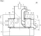
- Fig. 1 is a longitudinal sectional view of an adsorption treatment device 100 according to the present embodiment.
- Fig. 2 is a cross-sectional view taken along line II-II illustrated in Fig. 1 .
- Fig. 3 is an enlarged cross-sectional view of a main part of a cylindrical rotor 90 illustrated in Fig. 1 .
- Adsorption treatment device 100 according to the present embodiment will be described with reference to Figs. 1 to 3 .
- adsorption treatment device 100 adsorbs and removes a substance to be treated contained in a fluid to be treated F1 of a large air volume supplied into a treatment chamber 1 by using an adsorption unit 30 to be described later, and discharges clean air F2 that has been cleaned.
- Adsorption treatment device 100 blows a small amount of heated fluid F3 to adsorption unit 30 on which the substance to be treated adsorbed and removed is adsorbed, and thereby desorbs the substance to be treated from adsorption unit 30 and discharging the substance to be treated as a concentrated fluid F4.
- Adsorption treatment of a substance to be treated is performed in a second region R2 (see Fig. 2 ) of cylindrical rotor 90 described later.
- Second region R2 corresponds to an adsorption region.
- the desorption treatment of the substance to be treated is performed in a first region R1 (see Fig. 2 ) of cylindrical rotor 90 described later.
- First region R1 corresponds to a desorption region.
- the adsorption treatment is performed on adsorption unit 30 located in second region R2 after passing through first region R1.
- Second region R2 corresponds to an adsorption region.
- the desorption treatment is performed, again after the adsorption treatment, on adsorption unit 30 located in first region R1 after passing through second region R2. As described above, in adsorption treatment device 100, the adsorption treatment and the desorption treatment are continuously performed.
- adsorption treatment device 100 includes cylindrical rotor 90 as a rotating body, a first flow path formation member 2, an inner peripheral side flow path formation member 4 as an inlet side flow path formation member, and an outer peripheral side flow path formation member 5 as an outlet side flow path formation member.
- Cylindrical rotor 90 is installed in treatment chamber 1. Cylindrical rotor 90 is provided so that the fluid can flow in the radial direction. Cylindrical rotor 90 is provided rotatably about cylinder axis C. Cylindrical rotor 90 is rotatably supported by a plurality of support members 6 such as supporting posts such that cylinder axis C is directed in the vertical direction.
- Cylindrical rotor 90 includes a pair of disks 10, a plurality of partition plates 20, and a plurality of adsorption units 30.
- the pair of disks 10 is disposed so as to face each other.
- the pair of disks 10 include a first disk 11 and a second disk 12.
- An opening 11a is provided in a central portion of first disk 11.
- First disk 11 and second disk 12 are arranged to face each other such that center positions thereof overlap each other when viewed from the direction of cylinder axis C of cylindrical rotor 90.
- First disk 11 and second disk 12 are provided at a distance so that partition plates 20 and adsorption unit 30 can be disposed therebetween.
- the plurality of partition plates 20 partition a space between the pair of disks 10 into a plurality of space portions S (see Fig. 3 ) independent from each other in the circumferential direction. Specifically, the plurality of partition plates 20 partition the space between the pair of disks 10 in the portion where first disk 11 and second disk 12 overlap when viewed from the direction of cylinder axis C into the plurality of space portions S independent from each other in the circumferential direction.
- the plurality of partition plates 20 are arranged such that centers O (see Fig. 3 ) thereof are arranged at a predetermined pitch in the circumferential direction.
- the plurality of partition plates 20 are attached between the pair of disks 10 air-tightly and/or liquid-tightly in the direction of cylinder axis C.
- the plurality of adsorption units 30 are respectively accommodated in the plurality of independent space portions S.
- the plurality of adsorption units 30 are arranged in the circumferential direction at a predetermined pitch.
- Each of adsorption units 30 has, for example, a rectangular block shape.
- Adsorption units 30 are configured by an adsorbent containing any of activated alumina, silica gel, activated carbon, and zeolite.
- adsorbent containing any of activated alumina, silica gel, activated carbon, and zeolite.
- granular, powder, or honeycomb activated carbon or zeolite is used as the adsorbent.
- Activated carbon and zeolite are excellent in adsorbing and desorbing low-concentration organic compounds.
- the pressure loss of the fluid can be reduced, and the treatment capacity can be increased. Furthermore, clogging due to a solid such as dust can be suppressed. A detailed configuration of adsorption units 30 will be described later.
- cylindrical rotor 90 configured by alternately arranging the plurality of partition plates 20 and the plurality of adsorption units 30 in the circumferential direction between the pair of disks 10 to provide a cylindrical shape, a central space 90a is defined so as to communicate with opening 11a of first disk 11.
- first flow path formation member 2 is configured to allow cylindrical rotor 90 to rotate about cylinder axis C while airtightly maintaining the inside of first flow path formation member 2 and central space 90a of cylindrical rotor 90.
- a flange is provided on the one end side of first flow path formation member 2, and ab annular sealing member is sandwiched between the flange and first disk 11 located at the peripheral edge of opening 11a. The other end side of first flow path formation member 2 is drawn out of treatment chamber 1.
- inner peripheral side flow path formation member 4 In central space 90a which is on the inner peripheral side of cylindrical rotor 90, inner peripheral side flow path formation member 4 is disposed. Outer peripheral side flow path formation member 5 is disposed on the outer peripheral side of cylindrical rotor 90. Inner peripheral side flow path formation member 4 and outer peripheral side flow path formation member 5 are disposed to face each other on the inner peripheral side and the outer peripheral side of cylindrical rotor 90 so as to sandwich a part of cylindrical rotor 90 in the circumferential direction.
- Inner peripheral side flow path formation member 4 extends in central space 90a along cylinder axis C and extends from opening 11a toward the outside of cylindrical rotor 90.
- An inner peripheral side opening end portion 4a facing the inner peripheral side of cylindrical rotor 90 is provided on one end side of inner peripheral side flow path formation member 4.
- An opening surface of inner peripheral side opening end portion 4a is provided so as to face a partial region on the inner peripheral side of cylindrical rotor 90 in the circumferential direction.
- the opening surface is provided between first disk 11 and second disk 12 of inner peripheral side flow path formation member 4 so as to face the inner peripheral side of cylindrical rotor 90 in the direction of cylinder axis C.
- the other end side of inner peripheral side flow path formation member 4 protrudes from an opening 2a provided in first flow path formation member 2 to the outside of first flow path formation member 2.
- An outer peripheral side opening end portion 5a facing the outer peripheral side of cylindrical rotor 90 is provided on one end side of outer peripheral side flow path formation member 5.
- An opening surface of outer peripheral side opening end portion 5a is provided so as to face a partial region on the outer peripheral side of the cylindrical rotor in the circumferential direction.
- the opening surface is provided between first disk 11 and second disk 12 so as to face the outer peripheral side of cylindrical rotor 90 in the direction of cylinder axis C.
- cylindrical rotor 90 includes first region R1 (see Fig. 2 ) and second region R2 (see Fig. 2 ) partitioned in the circumferential direction.
- the plurality of adsorption units 30 alternately move between first region R1 and second region R2 as cylindrical rotor 90 rotates.
- first region R1 is defined by airtightly communicating a part of the plurality of space portions S rotating along with the rotation of cylindrical rotor 90 to inner peripheral side flow path formation member 4 and outer peripheral side flow path formation member 5.
- inner peripheral side of first region R1 corresponds to an inlet portion E1
- outer peripheral side of first region R1 corresponds to an outlet portion E2.
- Cylindrical rotor 90 includes sealing members 40 respectively provided on the plurality of partition plates 20.
- the plurality of sealing members 40 are arranged side by side in the rotational direction of cylindrical rotor 90 (arrow direction in Figs. 2 and 3 ).
- Each of sealing members 40 includes an inner side sealing member 41 and an outer side sealing member 42.
- Each of the plurality of partition plates 20 includes an installation portion 22 for installing a main body 21 and sealing members 40.
- Main body 21 has, for example, a triangular tube shape.
- Installation portion 22 includes an inner peripheral side installation portion 23 and an outer peripheral side installation portion 24.
- Inner peripheral side installation portion 23 has a plate shape. Inner peripheral side installation portion 23 is provided to extend along cylinder axis C. Inner peripheral side installation portion 23 is provided so as to protrude radially inward of cylindrical rotor 90 from a top side portion of main body 21 located on the inner peripheral side of cylindrical rotor 90. Inner peripheral side installation portion 23 may be configured integrally with main body 21 or separately from main body 21. Inner peripheral side installation portion 23 has an inner peripheral side installation surface 23a for installing inner side sealing member 41 described later. Inner peripheral side installation surface 23a intersects with the rotational direction of cylindrical rotor 90.
- Outer peripheral side installation portion 24 has a plate shape. Outer peripheral side installation portion 24 is provided to extend along cylinder axis C. Outer peripheral side installation portion 24 is provided so as to protrude radially outward of cylindrical rotor 90 from a side surface of main body 21 located on the outer peripheral side of cylindrical rotor 90. Outer peripheral side installation portion 24 may be configured integrally with main body 21 or separately from main body 21. When outer peripheral side installation portion 24 is configured separately from main body 21, outer peripheral side installation portion 24 has a shape such as an L shape that can be attached to main body 21. Outer peripheral side installation portion 24 has an outer peripheral side installation surface 24a for installing outer side sealing member 42 described later. Outer peripheral side installation surface 24a intersects with the rotational direction of cylindrical rotor 90.
- Inner side sealing member 41 is installed on inner peripheral side installation surface 23a located on the inner peripheral side of cylindrical rotor 90 among the installation surfaces of partition plate 20. Inner side sealing member 41 extends between the pair of disks 10 from one disk (first disk 11) to the other disk (second disk 12). Inner side sealing member 41 protrudes from partition plate 20 toward radially inside of cylindrical rotor 90.
- Outer side sealing member 42 is installed on outer peripheral side installation surface 24a located on the outer peripheral side of cylindrical rotor 90 among the installation surfaces of partition plate 20. Outer side sealing member 42 extends between the pair of disks 10 from one disk (first disk 11) to the other disk (second disk 12). Outer side sealing member 42 protrudes from partition plate 20 toward radially outside of cylindrical rotor 90.
- inner peripheral side curved surfaces 4b and 4c curved along the rotational direction are respectively provided at a front edge in the rotational direction of inner peripheral side opening end portion 4a located on the front side in the rotational direction of cylindrical rotor 90 and at a rear edge in the rotational direction of inner peripheral side opening end portion 4a located on the rear side in the rotational direction of cylindrical rotor 90.
- outer peripheral side curved surfaces 5b and 5c curved along the rotational direction are respectively provided at a front edge in the rotational direction of outer peripheral side opening end portion 5a located on the front side in the rotational direction of cylindrical rotor 90 and at a rear edge in the rotational direction of outer peripheral side opening end portion 5a located on the rear side in the rotational direction of cylindrical rotor 90.
- inner side sealing member 41 slides with respect to inner peripheral side curved surfaces 4b and 4c
- outer side sealing member 42 slides with respect to outer peripheral side curved surfaces 5b and 5c, so that a part (first region R1) of the plurality of space portions S air-tightly communicates with inner peripheral side flow path formation member 4 and outer peripheral side flow path formation member 5.
- space portion S located between partition plate 20 between inner peripheral side curved surface 4b and outer peripheral side curved surface 5b and partition plate 20 located between inner peripheral side curved surface 4c and outer peripheral side curved surface 5c air-tightly communicates with inner peripheral side flow path formation member 4 and outer peripheral side flow path formation member 5.
- cylindrical rotor 90 is divided into first region R1 that air-tightly communicates with inner peripheral side flow path formation member 4 and outer peripheral side flow path formation member 5, and second region R2 that constitutes a flow path different from first region R1 instead of communicating with inner peripheral side flow path formation member 4 and outer peripheral side flow path formation member 5.
- a fluid is introduced into both first region R1 and second region R2.
- the direction in which the fluid passing through second region R2 flows and the direction in which the fluid passing through first region R1 flows are preferably opposite in the radial direction of cylindrical rotor 90.
- the fluid is introduced from the outer peripheral side toward the inner peripheral side of cylindrical rotor 90 so that the fluid passes through central space 90a of cylindrical rotor 90 located around inner peripheral side flow path formation member 4 and flows out through opening 11a of first disk 11.
- the fluid is introduced into first region R1 so that the fluid flows from the inner peripheral side toward the outer peripheral side of cylindrical rotor 90 after passing through inner peripheral side flow path formation member 4 passing through opening 1 1a of first disk 11.
- the fluid introduced into second region R2 is a fluid to be treated such as exhaust gas.
- the fluid to be treated includes an organic solvent as a substance to be treated.
- the fluid to be treated is cleaned.
- the exhaust gas is introduced into second region R2 of cylindrical rotor 90 from the outer peripheral side toward the inner peripheral side of cylindrical rotor 90.
- the exhaust gas introduced into second region R2 is cleaned when the exhaust gas passes through cylindrical rotor 90 along the radial direction by the organic solvent being adsorbed and removed by the plurality of adsorption units 30 located in second region R2.
- the cleaned exhaust gas flows from second region R2 as clean air into central space 90a of cylindrical rotor 90.
- the clean air flowing into central space 90a of cylindrical rotor 90 passes through central space 90a of the cylindrical rotor at a portion located around inner peripheral side flow path formation member 4, and flows out from opening 11a of first disk 11.
- the clean air flowing out from opening 11a is discharged to the outside of treatment chamber 1 through first flow path formation member 2.
- the fluid introduced into first region R1 is a heated fluid such as heated air.
- the organic solvent adsorbed by adsorption unit 30 is desorbed to regenerate adsorption unit 30 and to generate a concentrated fluid whose concentration of the organic solvent is increased.
- heated air is introduced from the other end side of inner peripheral side flow path formation member 4.
- the heated air introduced from the other end side of inner peripheral side flow path formation member 4 flows within of inner peripheral side flow path formation member 4 that passes through opening 11a of first disk 11, and is introduced into first region R1 from one end side of inner peripheral side flow path formation member 4.
- first region R1 When the heated air introduced into first region R1 passes through cylindrical rotor 90 from the inner peripheral side toward the outer peripheral side of cylindrical rotor 90, the heated air desorbs the organic solvent adsorbed to the plurality of adsorption units 30 located in first region R1 by heat.
- the heated air containing the organic solvent is discharged as a concentrated fluid from first region R1 to outer peripheral side flow path formation member 5.
- the concentrated fluid discharged to outer peripheral side flow path formation member 5 is introduced into a post-treatment device in which post-treatment such as recovery or combustion is performed.
- Fig. 4 is a view illustrating a honeycomb shape which is the shape of adsorption element 200
- Fig. 5 is a partially enlarged view of the adsorption unit adopting the honeycomb shape which is the shape of adsorption element 200.
- Examples of a method for manufacturing adsorption element 200 include a method of forming a sheet into a honeycomb shape by mixed papermaking, a method of attaching an adsorbent to a sheet to be a base material and then forming the sheet into a honeycomb shape using an adhesive for forming a honeycomb, a method of forming a honeycomb shape in advance with a sheet to be a base material and then attaching an adsorbent, and a method of forming a honeycomb shape using an adsorbent and other framework materials (such as an extrusion molding method, for example).
- the manufacturing method is not particularly limited.
- Fig. 6 is an overall perspective view of adsorption unit 30 according to the present embodiment.
- Adsorption unit 30 includes plate-like adsorption elements 200 having the above-described honeycomb structure, and a frame body 30F1 that communicates the inflow side opening and the discharge side opening and holds the plurality of adsorption elements 200 laminated in a multilayer state so as to form the flow path of the fluid to be treated.
- a multilayer body 200A is provided by laminating adsorption elements 200 in the multilayer state.
- adsorption elements 200 may be fixed by frame body 30F1 alone, or adsorption elements 200 may be fixed to each other using an adhesive.
- an adhesive an inorganic binder can be used.
- the inorganic binder is, for example, soluble in water, uniformly dispersed in the sheet, and is cured by reaction, gelation, or the like during heat treatment, and firmly fixes the adsorbent and the skeleton material during the curing.
- thermal decomposition temperature 300°C or higher
- heat of reaction is generated by a highly reactive organic solvent
- catalytic properties that cause ignition and combustion of the sheet is low
- adsorption performance of the adsorbent (Ax) is less likely deteriorated by coating of the binder.
- a phosphate-based binder such as sodium hexametaphosphate and a silicate-based binder such as silicate soda are preferable.
- the inorganic binder for fixing and maintaining the adsorbent and fiber components and the inorganic binder for fixing and maintaining a flute portion 200a and a liner portion 200b constituting the honeycomb may not necessary be the same type of binder, and it is desirable to use a binder more suitable for productivity.
- frame body 30F1 has a substantially box shape as a whole so as to form an inflow side opening and a discharge side opening.
- Flanges 34 bent inward are provided respectively for the inflow side opening and the discharge side opening of a pair of side plates 33 located on the left and right.
- Flanges 32 bent inward are also provided each along an entire circumference of each of lid members 31 disposed on top and bottom.
- Flanges 36 are also provided at both left and right ends of partition body 35 so as to stand upright from partition body 35.
- frame body 30F 1 has a structure that can be divided when adsorption elements 200 are laminated at the time of assembly of adsorption unit 30, or when adsorption elements 200 are cleaned and replaced after assembling adsorption unit 30.
- joining using welding it is difficult to divide adsorption unit 30 once the unit is assembled.
- screwing and bolting it is easily possible to disassemble the unit. However, an unnecessary thickness is generated, as it is necessary to secure the volume of the screw and the bolt.
- rivets 37 that can be easily disassembled and requires only a small volume.
- the members fixed by rivets 37 are provided with through holes in advance.
- a screw, a bolt, or the like may be used as the fastening member.
- the rivets are illustrated with a ratio different from the actual size.
- a material used for frame body 30F1 is preferably thin, while it is also necessary to maintain the strength as a structural body. It may be appropriately set in consideration of the above points.
- Frame body 30F1 and rivet 37 may have sufficient strength, heat resistance, chemical resistance, and the like under the conditions of use. It is preferable to use a metal material such as iron, stainless steel, or aluminum, a resin material such as acryl, bakelite, or melanin, or the like.
- Adsorption unit 30 of the present embodiment may be used alone, or a plurality of adsorption units may be laminated and used.
- Fig. 7 is an overall perspective view of adsorption unit 30A in the present embodiment.
- An adsorption unit 30A has a larger number of laminated adsorption elements 200 than in the configuration of adsorption unit 30.
- a configuration in which the number of laminated layers in multilayer bodies 200A is simply increased may be adopted, but adsorption elements 200 may be damaged by contact with or rubbing between multilayer bodies 200A.
- partition bodies 35 are disposed between multilayer bodies 200A.
- Partition bodies 35 are provided so as to extend from the inflow side opening to the discharge side opening, and divides multilayer bodies 200A.
- partition bodies 35 contact with and rubbing between multilayer bodies 200A can be suppressed.
- adsorption elements 200 can also be held by partition bodies 35, the stability of the structure of laminated multilayer bodies 200A can be increased. Since multilayer bodies 200A is fixed by frame body 30F1 and partition bodies 35, adsorption elements 200 constituting multilayer bodies 200A may be or may not be fixed to each other using an adhesive.
- the number of laminated layers in multilayer body 200A and the number of partition bodies 35 can be appropriately changed according to the strength and performance required for adsorption unit 30, but partition bodies 35 may be provided so as to divide the entire multilayer body into about 2 to 5 depending on the number of layers of adsorption elements 200 forming multilayer body 200A.
- the material used for partition body 35 may have sufficient strength, heat resistance, chemical resistance, and the like under the same conditions of use as frame body 30F1 and the like. It is preferable to use a metal material such as iron, stainless steel, or aluminum, a resin material such as acryl, bakelite, or melanin, or the like.
- Fig. 8 is an overall perspective view of adsorption unit 30B according to the present embodiment.
- Adsorption unit 30B basically has the same configuration as adsorption unit 30A, but flanges 36 are provided at left and right ends of partition body 35 so as to stand upright from partition body 35. Side plates 33 and flanges 36 at both ends of partition body 35 are also fixed by rivets 37 as fastening members. The members fixed by rivets 37 are provided with through holes in advance.
- partition body 35 can be fixed to side plates 33. With this, the weight of multilayer body 200A divided by partition bodies 35 can be dispersed by partition bodies 35.
- Fig. 11 is an overall perspective view illustrating adsorption unit 30C.
- Adsorption unit 30C is different from adsorption unit 30B illustrated in Fig. 8 in the configuration with from frame body 30F1.
- Frame body 30F2 used in adsorption unit 30C employs a belt-shaped plate.
- the multilayer state of multilayer body 200A and partition body 35 is the same as that of adsorption unit 30B.
- Upper and lower band plates 31p are arranged on the lower surface side and the upper surface side of multilayer body 200A, and both ends of each plate are bent in an L shape to form a flange 32.
- side band plates 33p are arranged in parallel at two locations along the flow direction from the inflow side opening to the discharge side opening.
- Flanges 32 of upper and lower band plates 31p and the end portions of side band plates 33p are fastened to each other with rivets 37, and an intersecting region between flanges 36 of partition body 35 and side band plates 33p is fastened with rivets 37.
- adopting the configuration of adsorption unit 30C facilitates the assembly of adsorption unit 30C, and the cleaning and replacement of multilayer body 200A or adsorption elements 200 after the assembly of adsorption unit 30C.
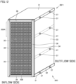
- Fig. 12 is an overall perspective view illustrating adsorption unit 30D.
- Figs. 13 to 16 are views illustrating a transverse cross-sectional structure of a sealing member 38.
- a basic configuration of adsorption unit 30D is the same as that of adsorption unit 30B illustrated in Fig. 8 .
- the difference lies in that flange 32 and flange 34 of the inflow side opening are provided with sealing member 38 made of an elastic member in an annular shape so as to surround the opening of frame body 30F1.
- adsorption unit 30D illustrated in Fig. 12 shows a case where sealing member 38 is provided only on the inflow side
- any case may be employed where sealing member 38 is provided only on the discharge side and a case where the sealing member is provided on the inflow side and the discharge side.
- Sealing member 38 is fixed to flange 32 and flange 34 using an adhesive or the like.
- Sealing member 38 is preferably an elastic member, and particularly preferably a rubber material.
- the rubber material may be selected in consideration of heat resistance, chemical resistance, and the like depending on the conditions of use.
- Figs. 12 to 15 illustrate transverse cross-sectional shapes of sealing member 38.
- sealing member 38 various cross-sectional shapes can be adopted other than those illustrated.
- Fig. 17 is an overall perspective view illustrating adsorption unit 30E.
- Figs. 18 to 21 are views illustrating a transverse cross-sectional structure of an annular groove M1 and sealing member 38.
- a basic configuration of adsorption unit 30E is the same as that of adsorption unit 30D illustrated in Fig. 12 .
- the difference lies in that flange 32 and flange 34 of the inflow side opening are provided with a pair of wall portions 38w so as to provide annular groove M1, and sealing member 38 is disposed in annular groove M1.
- wall portions 38w the same material as that of frame body 30F1 is preferably used and is preferably integrated with frame body 30F1. Examples include fixation using rivets and fixation by welding.
- Annular groove M1 has an internal depth of about 10 mm and an internal width of about 20 mm.
- Figs. 18 to 21 illustrate transverse cross-sectional shapes of sealing member 38. As with the structure illustrated in Figs. 13 to 16 described above, various cross-sectional shapes can be adopted for sealing member 38.
- sealing member 38 By disposing sealing member 38 inside annular groove M1 in this manner, displacement and breakage of sealing member 38 may be prevented. As a result, it is possible to further improve the sealing properties of the flow path when sealing member 38 is installed in cylindrical rotor 90 of adsorption treatment device 100.
- Fig. 22 is an overall perspective view illustrating adsorption unit 30F.
- Adsorption unit 30F has the same basic configuration as that of adsorption unit 30B illustrated in Fig. 8 , and is different in that a protection net 70 as a protection member is provided at the inflow side opening of frame body 30F 1.
- the present embodiment illustrates a case where protection net 70 in a lattice shape is adopted, it is possible to employ a nonwoven fabric shape, a punching board shape, or a net shape in consideration of the protection of the surface of adsorption elements 200 and performance in the passage of the fluid. It is particularly preferable to use lattice shape and net shape in the viewpoint of achieving both surface protection and performance in the passage of the fluid.
- a treatment system including a pre-treatment device that treats a treatment fluid before introducing the treatment fluid into adsorption treatment device 100 and/or a post-treatment device that treats a desorbed gas discharged from adsorption treatment device 100.
- the pre-treatment device examples include a dust removing filter, a pre-adsorption unit provided with an adsorbent such as granular activated carbon, impregnated activated carbon, activated alumina, or zeolite for removing a deteriorated component of adsorption element 200, a scrubber for removing a water-soluble component, a roll filter unit for removing a coating mist, a gas cooler and/or a gas heater for adjusting the temperature and humidity of a treatment fluid, a gas cooler and/or a separator for liquefying and recovering the treatment fluid in advance, and a recovery device equipped with activated carbon for liquefying and recovering the treatment fluid in advance.
- an adsorbent such as granular activated carbon, impregnated activated carbon, activated alumina, or zeolite for removing a deteriorated component of adsorption element 200
- a scrubber for removing a water-soluble component
- a roll filter unit for removing
- Examples of the post-treatment device include a combustion device (such as direct combustion, catalytic combustion, heat storage combustion) that performs combustion treatment of a desorbed gas discharged from adsorption treatment device 100, a gas cooler and/or a separator for liquefying and recovering the desorbed gas, a recovery device equipped with activated carbon for liquefying and recovering the desorbed gas, and a buffer device filled with an adsorbent for leveling the concentration of the desorbed gas.
- a combustion device such as direct combustion, catalytic combustion, heat storage combustion
- a gas cooler and/or a separator for liquefying and recovering the desorbed gas
- a recovery device equipped with activated carbon for liquefying and recovering the desorbed gas
- a buffer device filled with an adsorbent for leveling the concentration of the desorbed gas.
- One or more of these pretreatment facilities and/or post-treatment facilities may be provided according to the conditions of treatment.
Landscapes
- Chemical & Material Sciences (AREA)
- Chemical Kinetics & Catalysis (AREA)
- Analytical Chemistry (AREA)
- Organic Chemistry (AREA)
- Engineering & Computer Science (AREA)
- General Chemical & Material Sciences (AREA)
- Oil, Petroleum & Natural Gas (AREA)
- Physics & Mathematics (AREA)
- Geometry (AREA)
- Inorganic Chemistry (AREA)
- Separation Of Gases By Adsorption (AREA)
- Treating Waste Gases (AREA)
Abstract
Description
- The present invention relates to an adsorption treatment device and a treatment system each of which adopts an adsorption unit, and more particularly to a structure of the adsorption unit.
- Conventionally, as a method for treating a fluid to be treated of a large flow rate and containing a low-concentration substance to be treated, there is an adsorption treatment method. As an example of this treatment method, there is a concentration method with which a large air volume of a fluid to be treated is caused to flow into an adsorption region of an adsorption unit including a continuously rotating adsorption element to adsorb and remove a substance to be treated contained in the fluid to be treated.
- On the other hand, a heated fluid of a small amount is caused to flow into a desorption region separate from the adsorption region into which the fluid to be treated flows, and the substance to be treated contained in the fluid to be treated of a large air volume is moved to the heated fluid of a small air volume. As described above, it is possible to reduce the total treatment cost by generating a small air volume of so-called concentrated fluid containing a high concentration substance to be treated, and by separately subjecting the concentrated fluid to secondary treatment by a treatment apparatus provided outside.
- An adsorption unit, an adsorption treatment device, and an organic solvent recovery system employing such a treatment technique are disclosed in
Japanese Patent Laying-Open No. 2019-209267 Japanese Patent Laying-Open No. 2019-209268 WO 2017/006785 (PTL 3),WO 2016/189958 (PTL 4),Japanese Patent Laying-Open No. 2012-166155 -
- PTL 1:
Japanese Patent Laying-Open No. 2019-209267 - PTL 2:
Japanese Patent Laying-Open No. 2019-209268 - PTL 3:
WO 2017/006785 - PTL 4:
WO 2016/189958 - PTL 5:
Japanese Patent Laying-Open No. 2012-166155 - However, no specific structure of the adsorption unit including the adsorbent is disclosed. In recent years, there has been a demand for an adsorption unit for treating a fluid to be treated with higher performance.
- The present invention has been made to solve the above problems, and an object of the present invention is to provide an adsorption unit that suppresses leakage of a fluid to be treated from an adsorption element, and has a configuration in which the adsorption element may not be easily damaged. Still another object is to provide an adsorption treatment device and a treatment system adopting the adsorption unit.
- An adsorption unit according to the present disclosure includes: a multilayer body in which a plurality of plate-shaped adsorption elements each having a honeycomb structure are laminated; a frame body that communicates an inflow side opening and a discharge side opening, and holds a plurality of the multilayer bodies in a multilayer state such that a flow path of a fluid to be treated is provided.
- The adsorption unit according to another embodiment further includes: a partition body that partitions the plurality of multilayer bodies.
- In the adsorption unit according to another embodiment, the multilayer body includes the adsorption elements are fixed to and integrated with each other.
- In the adsorption unit according to another embodiment, an end portion of the partition body is fixed to the frame body using a fastening member.
- In the adsorption unit according to another embodiment, the fastening member is a rivet.
- In the adsorption unit according to another embodiment, the frame body includes a tubular frame defining the inflow side opening and the discharge side opening, and a sealing member is annularly disposed on an end surface of at least one of the inflow side opening and the discharge side opening of the frame.
- In the adsorption unit according to another embodiment, a pair of wall portions are provided such that an annular groove is provided on the end surface of at least one of the inflow side opening and the discharge side opening, and the sealing member is disposed in the annular groove.
- In the adsorption unit according to another embodiment, the end surface of at least one of the inflow side opening and the discharge side opening is provided with a protection member that covers the inflow side opening and the discharge side opening without hindering inflow and outflow of the fluid to be treated.
- In the adsorption unit according to another embodiment, the protection member has a lattice shape or a net shape.
- An adsorption treatment device according to the present disclosure is provided with an adsorption unit that treats a substance to be treated contained in a fluid to be treated, and the adsorption treatment device includes: an adsorption region that causes the adsorption unit to adsorb a substance to be treated contained in the fluid to be treated; and a desorption region for desorbing the substance to be treated adsorbed to the adsorption unit from the adsorption unit, wherein the adsorption unit is any one of the adsorption units described above.
- In the adsorption treatment device according to another embodiment, the adsorption unit includes a plurality of adsorption units disposed around a rotation center, and the plurality of adsorption units alternately move between the adsorption region and the desorption region by the adsorption units rotating annularly about the rotation center.
- A treatment system according to the present disclosure includes: the adsorption treatment device described above; and a pre-treatment device and/or a post-treatment device, the pre-treatment device treating a fluid to be treated before the fluid to be treated is introduced into the adsorption treatment device, the post-treatment device treating a desorbed gas discharged from the adsorption treatment device.
- According to an adsorption unit of the present disclosure, leakage of a fluid to be treated from an adsorption element is suppressed, and the adsorption element may not be easily damaged. Furthermore, according to an adsorption treatment device and a treatment system of the present disclosure, it is possible to treat the fluid to be treated with higher performance by using the adsorption unit of the present disclosure.
-
-
Fig. 1 is a longitudinal sectional view of an adsorption treatment device according to a first embodiment. -
Fig. 2 is a cross-sectional view taken along line II-II illustrated inFig. 1 . -
Fig. 3 is an enlarged cross-sectional view of a main part of a cylindrical rotor illustrated inFig. 1 . -
Fig. 4 is a view illustrating a honeycomb shape which is a shape of an adsorption element in the embodiment. -
Fig. 5 is a partially enlarged view of an adsorption unit adopting a honeycomb shape which is a shape of an adsorption element in the first embodiment. -
Fig. 6 is an overall perspective view of the adsorption unit according to the first embodiment. -
Fig. 7 is an overall perspective view of an adsorption unit having another configuration according to a second embodiment. -
Fig. 8 is an overall perspective view of an adsorption unit having another configuration according to a third embodiment. -
Fig. 9 is a cross-sectional view taken along line IX-IX inFig. 8 . -
Fig. 10 is a transverse cross-sectional view illustrating a structure of a partition body in a cross section taken along line X-X inFig. 9 . -
Fig. 11 is an overall perspective view illustrating an adsorption unit according to a fourth embodiment. -
Fig. 12 is an overall perspective view illustrating an adsorption unit according to a fifth embodiment. -
Fig. 13 is a view illustrating a transverse cross-sectional structure of a sealing member provided in the adsorption unit in the fifth embodiment. -
Fig. 14 is a view illustrating another transverse cross-sectional structure of the sealing member provided in the adsorption unit in the fifth embodiment. -
Fig. 15 is a view illustrating another transverse cross-sectional structure of the sealing member provided in the adsorption unit in the fifth embodiment. -
Fig. 16 is a view illustrating another transverse cross-sectional structure of the sealing member provided in the adsorption unit in the fifth embodiment. -
Fig. 17 is an overall perspective view illustrating a configuration of an adsorption unit according to a sixth embodiment. -
Fig. 18 is a view illustrating a transverse cross-sectional structure of an annular groove and a sealing member provided in the adsorption unit in the sixth embodiment. -
Fig. 19 is a view illustrating a transverse cross-sectional structure of another annular groove and another sealing member provided in the adsorption unit in the sixth embodiment. -
Fig. 20 is a view illustrating a transverse cross-sectional structure of another annular groove and another sealing member provided in the adsorption unit in the sixth embodiment. -
Fig. 21 is a view illustrating a transverse cross-sectional structure of another annular groove and another sealing member provided in the adsorption unit in the sixth embodiment. -
Fig. 22 is an overall perspective view illustrating a configuration of an adsorption unit according to a seventh embodiment. - Hereinafter, an adsorption unit, an adsorption treatment device, and a treatment system according to embodiments of the present invention will be described with reference to the drawings. In the embodiments described below, when referring to numbers, amounts, and the like, the scope of the present invention is not necessarily limited to these numbers, amounts, and the like unless otherwise specified. The same components and corresponding components are denoted by the same reference numerals, and redundant description may not be repeated. It is intended from the beginning to appropriately combine and use configurations in the embodiments.
-
Fig. 1 is a longitudinal sectional view of anadsorption treatment device 100 according to the present embodiment.Fig. 2 is a cross-sectional view taken along line II-II illustrated inFig. 1 .Fig. 3 is an enlarged cross-sectional view of a main part of acylindrical rotor 90 illustrated inFig. 1 .Adsorption treatment device 100 according to the present embodiment will be described with reference toFigs. 1 to 3 . - As shown in
Fig. 1 ,adsorption treatment device 100 according to the present embodiment adsorbs and removes a substance to be treated contained in a fluid to be treated F1 of a large air volume supplied into atreatment chamber 1 by using anadsorption unit 30 to be described later, and discharges clean air F2 that has been cleaned.Adsorption treatment device 100 blows a small amount of heated fluid F3 toadsorption unit 30 on which the substance to be treated adsorbed and removed is adsorbed, and thereby desorbs the substance to be treated fromadsorption unit 30 and discharging the substance to be treated as a concentrated fluid F4. - Adsorption treatment of a substance to be treated is performed in a second region R2 (see
Fig. 2 ) ofcylindrical rotor 90 described later. Second region R2 corresponds to an adsorption region. The desorption treatment of the substance to be treated is performed in a first region R1 (seeFig. 2 ) ofcylindrical rotor 90 described later. First region R1 corresponds to a desorption region. By the rotation ofcylindrical rotor 90 about a cylinder axis C, the adsorption treatment is performed onadsorption unit 30 located in second region R2 after passing through first region R1. Second region R2 corresponds to an adsorption region. - The desorption treatment is performed, again after the adsorption treatment, on
adsorption unit 30 located in first region R1 after passing through second region R2. As described above, inadsorption treatment device 100, the adsorption treatment and the desorption treatment are continuously performed. - As shown in
Figs. 1 to 3 ,adsorption treatment device 100 includescylindrical rotor 90 as a rotating body, a first flowpath formation member 2, an inner peripheral side flowpath formation member 4 as an inlet side flow path formation member, and an outer peripheral side flowpath formation member 5 as an outlet side flow path formation member. -
Cylindrical rotor 90 is installed intreatment chamber 1.Cylindrical rotor 90 is provided so that the fluid can flow in the radial direction.Cylindrical rotor 90 is provided rotatably about cylinder axisC. Cylindrical rotor 90 is rotatably supported by a plurality ofsupport members 6 such as supporting posts such that cylinder axis C is directed in the vertical direction. -
Cylindrical rotor 90 includes a pair ofdisks 10, a plurality ofpartition plates 20, and a plurality ofadsorption units 30. - The pair of
disks 10 is disposed so as to face each other. The pair ofdisks 10 include afirst disk 11 and asecond disk 12. Anopening 11a is provided in a central portion offirst disk 11.First disk 11 andsecond disk 12 are arranged to face each other such that center positions thereof overlap each other when viewed from the direction of cylinder axis C ofcylindrical rotor 90.First disk 11 andsecond disk 12 are provided at a distance so thatpartition plates 20 andadsorption unit 30 can be disposed therebetween. - The plurality of
partition plates 20 partition a space between the pair ofdisks 10 into a plurality of space portions S (seeFig. 3 ) independent from each other in the circumferential direction. Specifically, the plurality ofpartition plates 20 partition the space between the pair ofdisks 10 in the portion wherefirst disk 11 andsecond disk 12 overlap when viewed from the direction of cylinder axis C into the plurality of space portions S independent from each other in the circumferential direction. - The plurality of
partition plates 20 are arranged such that centers O (seeFig. 3 ) thereof are arranged at a predetermined pitch in the circumferential direction. The plurality ofpartition plates 20 are attached between the pair ofdisks 10 air-tightly and/or liquid-tightly in the direction of cylinder axis C. - The plurality of
adsorption units 30 are respectively accommodated in the plurality of independent space portions S. The plurality ofadsorption units 30 are arranged in the circumferential direction at a predetermined pitch. Each ofadsorption units 30 has, for example, a rectangular block shape. -
Adsorption units 30 are configured by an adsorbent containing any of activated alumina, silica gel, activated carbon, and zeolite. Preferably, granular, powder, or honeycomb activated carbon or zeolite is used as the adsorbent. Activated carbon and zeolite are excellent in adsorbing and desorbing low-concentration organic compounds. In addition, by providing in the honeycomb shape, the pressure loss of the fluid can be reduced, and the treatment capacity can be increased. Furthermore, clogging due to a solid such as dust can be suppressed. A detailed configuration ofadsorption units 30 will be described later. - In
cylindrical rotor 90 configured by alternately arranging the plurality ofpartition plates 20 and the plurality ofadsorption units 30 in the circumferential direction between the pair ofdisks 10 to provide a cylindrical shape, acentral space 90a is defined so as to communicate withopening 11a offirst disk 11. - One end side of first flow
path formation member 2 is configured to allowcylindrical rotor 90 to rotate about cylinder axis C while airtightly maintaining the inside of first flowpath formation member 2 andcentral space 90a ofcylindrical rotor 90. Specifically, for example, a flange is provided on the one end side of first flowpath formation member 2, and ab annular sealing member is sandwiched between the flange andfirst disk 11 located at the peripheral edge ofopening 11a. The other end side of first flowpath formation member 2 is drawn out oftreatment chamber 1. - In
central space 90a which is on the inner peripheral side ofcylindrical rotor 90, inner peripheral side flowpath formation member 4 is disposed. Outer peripheral side flowpath formation member 5 is disposed on the outer peripheral side ofcylindrical rotor 90. Inner peripheral side flowpath formation member 4 and outer peripheral side flowpath formation member 5 are disposed to face each other on the inner peripheral side and the outer peripheral side ofcylindrical rotor 90 so as to sandwich a part ofcylindrical rotor 90 in the circumferential direction. - Inner peripheral side flow
path formation member 4 extends incentral space 90a along cylinder axis C and extends from opening 11a toward the outside ofcylindrical rotor 90. - An inner peripheral side opening
end portion 4a facing the inner peripheral side ofcylindrical rotor 90 is provided on one end side of inner peripheral side flowpath formation member 4. An opening surface of inner peripheral side openingend portion 4a is provided so as to face a partial region on the inner peripheral side ofcylindrical rotor 90 in the circumferential direction. The opening surface is provided betweenfirst disk 11 andsecond disk 12 of inner peripheral side flowpath formation member 4 so as to face the inner peripheral side ofcylindrical rotor 90 in the direction of cylinder axis C. The other end side of inner peripheral side flowpath formation member 4 protrudes from anopening 2a provided in first flowpath formation member 2 to the outside of first flowpath formation member 2. - An outer peripheral side opening
end portion 5a facing the outer peripheral side ofcylindrical rotor 90 is provided on one end side of outer peripheral side flowpath formation member 5. An opening surface of outer peripheral side openingend portion 5a is provided so as to face a partial region on the outer peripheral side of the cylindrical rotor in the circumferential direction. The opening surface is provided betweenfirst disk 11 andsecond disk 12 so as to face the outer peripheral side ofcylindrical rotor 90 in the direction of cylinder axis C. - As shown in
Fig. 2 ,cylindrical rotor 90 includes first region R1 (seeFig. 2 ) and second region R2 (seeFig. 2 ) partitioned in the circumferential direction. The plurality ofadsorption units 30 alternately move between first region R1 and second region R2 ascylindrical rotor 90 rotates. - As shown in
Fig. 3 , first region R1 is defined by airtightly communicating a part of the plurality of space portions S rotating along with the rotation ofcylindrical rotor 90 to inner peripheral side flowpath formation member 4 and outer peripheral side flowpath formation member 5. As described later, when the fluid flows from the inner peripheral side toward the outer peripheral side in first region R1, the inner peripheral side of first region R1 corresponds to an inlet portion E1, and the outer peripheral side of first region R1 corresponds to an outlet portion E2. -
Cylindrical rotor 90 includes sealingmembers 40 respectively provided on the plurality ofpartition plates 20. The plurality of sealingmembers 40 are arranged side by side in the rotational direction of cylindrical rotor 90 (arrow direction inFigs. 2 and3 ). Each of sealingmembers 40 includes an innerside sealing member 41 and an outerside sealing member 42. Each of the plurality ofpartition plates 20 includes aninstallation portion 22 for installing amain body 21 and sealingmembers 40.Main body 21 has, for example, a triangular tube shape.Installation portion 22 includes an inner peripheralside installation portion 23 and an outer peripheralside installation portion 24. - Inner peripheral
side installation portion 23 has a plate shape. Inner peripheralside installation portion 23 is provided to extend along cylinder axis C. Inner peripheralside installation portion 23 is provided so as to protrude radially inward ofcylindrical rotor 90 from a top side portion ofmain body 21 located on the inner peripheral side ofcylindrical rotor 90. Inner peripheralside installation portion 23 may be configured integrally withmain body 21 or separately frommain body 21. Inner peripheralside installation portion 23 has an inner peripheralside installation surface 23a for installing innerside sealing member 41 described later. Inner peripheralside installation surface 23a intersects with the rotational direction ofcylindrical rotor 90. - Outer peripheral
side installation portion 24 has a plate shape. Outer peripheralside installation portion 24 is provided to extend along cylinder axis C. Outer peripheralside installation portion 24 is provided so as to protrude radially outward ofcylindrical rotor 90 from a side surface ofmain body 21 located on the outer peripheral side ofcylindrical rotor 90. Outer peripheralside installation portion 24 may be configured integrally withmain body 21 or separately frommain body 21. When outer peripheralside installation portion 24 is configured separately frommain body 21, outer peripheralside installation portion 24 has a shape such as an L shape that can be attached tomain body 21. Outer peripheralside installation portion 24 has an outer peripheralside installation surface 24a for installing outerside sealing member 42 described later. Outer peripheralside installation surface 24a intersects with the rotational direction ofcylindrical rotor 90. - Inner
side sealing member 41 is installed on inner peripheralside installation surface 23a located on the inner peripheral side ofcylindrical rotor 90 among the installation surfaces ofpartition plate 20. Innerside sealing member 41 extends between the pair ofdisks 10 from one disk (first disk 11) to the other disk (second disk 12). Innerside sealing member 41 protrudes frompartition plate 20 toward radially inside ofcylindrical rotor 90. - Outer
side sealing member 42 is installed on outer peripheralside installation surface 24a located on the outer peripheral side ofcylindrical rotor 90 among the installation surfaces ofpartition plate 20. Outerside sealing member 42 extends between the pair ofdisks 10 from one disk (first disk 11) to the other disk (second disk 12). Outerside sealing member 42 protrudes frompartition plate 20 toward radially outside ofcylindrical rotor 90. - In inner peripheral side flow
path formation member 4, inner peripheral side curved surfaces 4b and 4c curved along the rotational direction are respectively provided at a front edge in the rotational direction of inner peripheral side openingend portion 4a located on the front side in the rotational direction ofcylindrical rotor 90 and at a rear edge in the rotational direction of inner peripheral side openingend portion 4a located on the rear side in the rotational direction ofcylindrical rotor 90. - In outer peripheral side flow
path formation member 5, outer peripheral side curved surfaces 5b and 5c curved along the rotational direction are respectively provided at a front edge in the rotational direction of outer peripheral side openingend portion 5a located on the front side in the rotational direction ofcylindrical rotor 90 and at a rear edge in the rotational direction of outer peripheral side openingend portion 5a located on the rear side in the rotational direction ofcylindrical rotor 90. - As
cylindrical rotor 90 rotates, innerside sealing member 41 slides with respect to inner peripheral side curved surfaces 4b and 4c, and outerside sealing member 42 slides with respect to outer peripheral side curved surfaces 5b and 5c, so that a part (first region R1) of the plurality of space portions S air-tightly communicates with inner peripheral side flowpath formation member 4 and outer peripheral side flowpath formation member 5. - Specifically, space portion S located between
partition plate 20 between inner peripheral side curvedsurface 4b and outer peripheral side curvedsurface 5b andpartition plate 20 located between inner peripheral side curvedsurface 4c and outer peripheral side curvedsurface 5c air-tightly communicates with inner peripheral side flowpath formation member 4 and outer peripheral side flowpath formation member 5. - In this manner,
cylindrical rotor 90 is divided into first region R1 that air-tightly communicates with inner peripheral side flowpath formation member 4 and outer peripheral side flowpath formation member 5, and second region R2 that constitutes a flow path different from first region R1 instead of communicating with inner peripheral side flowpath formation member 4 and outer peripheral side flowpath formation member 5. - As illustrated in
Figs. 1 and3 , a fluid is introduced into both first region R1 and second region R2. The direction in which the fluid passing through second region R2 flows and the direction in which the fluid passing through first region R1 flows are preferably opposite in the radial direction ofcylindrical rotor 90. - To second region R2, the fluid is introduced from the outer peripheral side toward the inner peripheral side of
cylindrical rotor 90 so that the fluid passes throughcentral space 90a ofcylindrical rotor 90 located around inner peripheral side flowpath formation member 4 and flows out throughopening 11a offirst disk 11. - On the other hand, the fluid is introduced into first region R1 so that the fluid flows from the inner peripheral side toward the outer peripheral side of
cylindrical rotor 90 after passing through inner peripheral side flowpath formation member 4 passing throughopening 1 1a offirst disk 11. - The fluid introduced into second region R2 is a fluid to be treated such as exhaust gas. The fluid to be treated includes an organic solvent as a substance to be treated. In the second region R2, the fluid to be treated is cleaned.
- At the time of cleaning, first, the exhaust gas is introduced into second region R2 of
cylindrical rotor 90 from the outer peripheral side toward the inner peripheral side ofcylindrical rotor 90. The exhaust gas introduced into second region R2 is cleaned when the exhaust gas passes throughcylindrical rotor 90 along the radial direction by the organic solvent being adsorbed and removed by the plurality ofadsorption units 30 located in second region R2. - The cleaned exhaust gas flows from second region R2 as clean air into
central space 90a ofcylindrical rotor 90. The clean air flowing intocentral space 90a ofcylindrical rotor 90 passes throughcentral space 90a of the cylindrical rotor at a portion located around inner peripheral side flowpath formation member 4, and flows out from opening 11a offirst disk 11. The clean air flowing out from opening 11a is discharged to the outside oftreatment chamber 1 through first flowpath formation member 2. - The fluid introduced into first region R1 is a heated fluid such as heated air. In first region R1, the organic solvent adsorbed by
adsorption unit 30 is desorbed to regenerateadsorption unit 30 and to generate a concentrated fluid whose concentration of the organic solvent is increased. - In order to desorb the organic solvent, heated air is introduced from the other end side of inner peripheral side flow
path formation member 4. The heated air introduced from the other end side of inner peripheral side flowpath formation member 4 flows within of inner peripheral side flowpath formation member 4 that passes throughopening 11a offirst disk 11, and is introduced into first region R1 from one end side of inner peripheral side flowpath formation member 4. - When the heated air introduced into first region R1 passes through
cylindrical rotor 90 from the inner peripheral side toward the outer peripheral side ofcylindrical rotor 90, the heated air desorbs the organic solvent adsorbed to the plurality ofadsorption units 30 located in first region R1 by heat. The heated air containing the organic solvent is discharged as a concentrated fluid from first region R1 to outer peripheral side flowpath formation member 5. The concentrated fluid discharged to outer peripheral side flowpath formation member 5 is introduced into a post-treatment device in which post-treatment such as recovery or combustion is performed. - Next, a configuration of an
adsorption element 200 used inadsorption unit 30 in the present embodiment will be described with reference toFigs. 4 and 5. Fig. 4 is a view illustrating a honeycomb shape which is the shape ofadsorption element 200, andFig. 5 is a partially enlarged view of the adsorption unit adopting the honeycomb shape which is the shape ofadsorption element 200. - Examples of a method for manufacturing
adsorption element 200 include a method of forming a sheet into a honeycomb shape by mixed papermaking, a method of attaching an adsorbent to a sheet to be a base material and then forming the sheet into a honeycomb shape using an adhesive for forming a honeycomb, a method of forming a honeycomb shape in advance with a sheet to be a base material and then attaching an adsorbent, and a method of forming a honeycomb shape using an adsorbent and other framework materials (such as an extrusion molding method, for example). However, the manufacturing method is not particularly limited. - A specific structure of
adsorption unit 30 according to the embodiment will be described with reference toFig. 6. Fig. 6 is an overall perspective view ofadsorption unit 30 according to the present embodiment. -
Adsorption unit 30 includes plate-like adsorption elements 200 having the above-described honeycomb structure, and a frame body 30F1 that communicates the inflow side opening and the discharge side opening and holds the plurality ofadsorption elements 200 laminated in a multilayer state so as to form the flow path of the fluid to be treated. Amultilayer body 200A is provided by laminatingadsorption elements 200 in the multilayer state. - When
multilayer body 200A is provided,adsorption elements 200 may be fixed by frame body 30F1 alone, oradsorption elements 200 may be fixed to each other using an adhesive. As the adhesive, an inorganic binder can be used. - The inorganic binder is, for example, soluble in water, uniformly dispersed in the sheet, and is cured by reaction, gelation, or the like during heat treatment, and firmly fixes the adsorbent and the skeleton material during the curing. In addition, it is preferable that thermal decomposition temperature of 300°C or higher, heat of reaction is generated by a highly reactive organic solvent, catalytic properties that cause ignition and combustion of the sheet is low, and adsorption performance of the adsorbent (Ax) is less likely deteriorated by coating of the binder. For example, a phosphate-based binder such as sodium hexametaphosphate and a silicate-based binder such as silicate soda are preferable.
- The inorganic binder for fixing and maintaining the adsorbent and fiber components and the inorganic binder for fixing and maintaining a
flute portion 200a and aliner portion 200b constituting the honeycomb may not necessary be the same type of binder, and it is desirable to use a binder more suitable for productivity. - In the present embodiment, frame body 30F1 has a substantially box shape as a whole so as to form an inflow side opening and a discharge side opening.
Flanges 34 bent inward are provided respectively for the inflow side opening and the discharge side opening of a pair ofside plates 33 located on the left and right.Flanges 32 bent inward are also provided each along an entire circumference of each oflid members 31 disposed on top and bottom.Flanges 36 are also provided at both left and right ends ofpartition body 35 so as to stand upright frompartition body 35. By providingflanges 32 andflanges 34 in this manner, it is possible to preventadsorption elements 200 from sticking out of frame body 30F1. - It is preferable that
frame body 30Fadsorption elements 200 are laminated at the time of assembly ofadsorption unit 30, or whenadsorption elements 200 are cleaned and replaced after assemblingadsorption unit 30. In the case of joining using welding, it is difficult to divideadsorption unit 30 once the unit is assembled. In the case of screwing and bolting, it is easily possible to disassemble the unit. However, an unnecessary thickness is generated, as it is necessary to secure the volume of the screw and the bolt. - Therefore, it is preferable to use, as the fastening member, rivets 37 that can be easily disassembled and requires only a small volume. The members fixed by
rivets 37 are provided with through holes in advance. When an increased volume does not provide any problem, a screw, a bolt, or the like may be used as the fastening member. In the drawings, in order to clarify positions to attachrivets 37, the rivets are illustrated with a ratio different from the actual size. - In order to increase an area of the opening of frame body 30F1, a material used for frame body 30F1 is preferably thin, while it is also necessary to maintain the strength as a structural body. It may be appropriately set in consideration of the above points. Frame body 30F1 and rivet 37 may have sufficient strength, heat resistance, chemical resistance, and the like under the conditions of use. It is preferable to use a metal material such as iron, stainless steel, or aluminum, a resin material such as acryl, bakelite, or melanin, or the like.
-
Adsorption unit 30 of the present embodiment may be used alone, or a plurality of adsorption units may be laminated and used. - A specific structure of an
adsorption unit 30A according to an embodiment will be described with reference toFig. 7. Fig. 7 is an overall perspective view ofadsorption unit 30A in the present embodiment. - An
adsorption unit 30A has a larger number oflaminated adsorption elements 200 than in the configuration ofadsorption unit 30. In addition, a configuration in which the number of laminated layers inmultilayer bodies 200A is simply increased may be adopted, but adsorptionelements 200 may be damaged by contact with or rubbing betweenmultilayer bodies 200A. - Therefore, as shown in the present embodiment,
partition bodies 35 are disposed betweenmultilayer bodies 200A.Partition bodies 35 are provided so as to extend from the inflow side opening to the discharge side opening, and dividesmultilayer bodies 200A. By disposingpartition bodies 35, contact with and rubbing betweenmultilayer bodies 200A can be suppressed. Furthermore, sinceadsorption elements 200 can also be held bypartition bodies 35, the stability of the structure of laminatedmultilayer bodies 200A can be increased. Sincemultilayer bodies 200A is fixed by frame body 30F1 andpartition bodies 35,adsorption elements 200 constitutingmultilayer bodies 200A may be or may not be fixed to each other using an adhesive. - The number of laminated layers in
multilayer body 200A and the number ofpartition bodies 35 can be appropriately changed according to the strength and performance required foradsorption unit 30, butpartition bodies 35 may be provided so as to divide the entire multilayer body into about 2 to 5 depending on the number of layers ofadsorption elements 200 formingmultilayer body 200A. - The material used for
partition body 35 may have sufficient strength, heat resistance, chemical resistance, and the like under the same conditions of use as frame body 30F1 and the like. It is preferable to use a metal material such as iron, stainless steel, or aluminum, a resin material such as acryl, bakelite, or melanin, or the like. - A specific structure of an
adsorption unit 30B according to an embodiment will be described with reference toFig. 8. Fig. 8 is an overall perspective view ofadsorption unit 30B according to the present embodiment. -
Adsorption unit 30B basically has the same configuration asadsorption unit 30A, butflanges 36 are provided at left and right ends ofpartition body 35 so as to stand upright frompartition body 35.Side plates 33 andflanges 36 at both ends ofpartition body 35 are also fixed byrivets 37 as fastening members. The members fixed byrivets 37 are provided with through holes in advance. - By providing
flanges 36 in this manner,partition body 35 can be fixed toside plates 33. With this, the weight ofmultilayer body 200A divided bypartition bodies 35 can be dispersed bypartition bodies 35. - An
adsorption unit 30C having another configuration will be described with reference toFig. 11. Fig. 11 is an overall perspective view illustratingadsorption unit 30C. -
Adsorption unit 30C is different fromadsorption unit 30B illustrated inFig. 8 in the configuration with from frame body 30F1. Frame body 30F2 used inadsorption unit 30C employs a belt-shaped plate. The multilayer state ofmultilayer body 200A andpartition body 35 is the same as that ofadsorption unit 30B. - Upper and
lower band plates 31p are arranged on the lower surface side and the upper surface side ofmultilayer body 200A, and both ends of each plate are bent in an L shape to form aflange 32. On the side surface ofmultilayer body 200A,side band plates 33p are arranged in parallel at two locations along the flow direction from the inflow side opening to the discharge side opening. -
Flanges 32 of upper andlower band plates 31p and the end portions ofside band plates 33p are fastened to each other withrivets 37, and an intersecting region betweenflanges 36 ofpartition body 35 andside band plates 33p is fastened withrivets 37. - When the shift of
multilayer body 200A andpartition body 35 in the flow direction from the inflow side opening to the discharge side opening does not cause a problem, adopting the configuration ofadsorption unit 30C facilitates the assembly ofadsorption unit 30C, and the cleaning and replacement ofmultilayer body 200A oradsorption elements 200 after the assembly ofadsorption unit 30C. - An
adsorption unit 30D will be described with reference toFigs. 12 to 16 .Fig. 12 is an overall perspective view illustratingadsorption unit 30D.Figs. 13 to 16 are views illustrating a transverse cross-sectional structure of a sealingmember 38. - A basic configuration of
adsorption unit 30D is the same as that ofadsorption unit 30B illustrated inFig. 8 . The difference lies in thatflange 32 andflange 34 of the inflow side opening are provided with sealingmember 38 made of an elastic member in an annular shape so as to surround the opening of frame body 30F1. By providing sealingmember 38, as shown inFigs. 1 to 3 , it is possible to improve the sealing properties of the flow path when sealingmember 38 is installed incylindrical rotor 90 ofadsorption treatment device 100. - Although
adsorption unit 30D illustrated inFig. 12 shows a case where sealingmember 38 is provided only on the inflow side, any case may be employed where sealingmember 38 is provided only on the discharge side and a case where the sealing member is provided on the inflow side and the discharge side. - Sealing
member 38 is fixed toflange 32 andflange 34 using an adhesive or the like. Sealingmember 38 is preferably an elastic member, and particularly preferably a rubber material. The rubber material may be selected in consideration of heat resistance, chemical resistance, and the like depending on the conditions of use. -
Figs. 12 to 15 illustrate transverse cross-sectional shapes of sealingmember 38. As sealingmember 38, various cross-sectional shapes can be adopted other than those illustrated. - An
adsorption unit 30E will be described with reference toFigs. 17 to 21 .Fig. 17 is an overall perspective view illustratingadsorption unit 30E.Figs. 18 to 21 are views illustrating a transverse cross-sectional structure of an annular groove M1 and sealingmember 38. - A basic configuration of
adsorption unit 30E is the same as that ofadsorption unit 30D illustrated inFig. 12 . The difference lies in thatflange 32 andflange 34 of the inflow side opening are provided with a pair ofwall portions 38w so as to provide annular groove M1, and sealingmember 38 is disposed in annular groove M1. Forwall portions 38w, the same material as that of frame body 30F1 is preferably used and is preferably integrated with frame body 30F1. Examples include fixation using rivets and fixation by welding. Annular groove M1 has an internal depth of about 10 mm and an internal width of about 20 mm. -
Figs. 18 to 21 illustrate transverse cross-sectional shapes of sealingmember 38. As with the structure illustrated inFigs. 13 to 16 described above, various cross-sectional shapes can be adopted for sealingmember 38. - By disposing sealing
member 38 inside annular groove M1 in this manner, displacement and breakage of sealingmember 38 may be prevented. As a result, it is possible to further improve the sealing properties of the flow path when sealingmember 38 is installed incylindrical rotor 90 ofadsorption treatment device 100. - An
adsorption unit 30F having another configuration will be described with reference toFig. 22. Fig. 22 is an overall perspective view illustratingadsorption unit 30F. -
Adsorption unit 30F has the same basic configuration as that ofadsorption unit 30B illustrated inFig. 8 , and is different in that aprotection net 70 as a protection member is provided at the inflow side opening offrame body 30F - Although the present embodiment illustrates a case where protection net 70 in a lattice shape is adopted, it is possible to employ a nonwoven fabric shape, a punching board shape, or a net shape in consideration of the protection of the surface of
adsorption elements 200 and performance in the passage of the fluid. It is particularly preferable to use lattice shape and net shape in the viewpoint of achieving both surface protection and performance in the passage of the fluid. - It is also possible to provide a treatment system including a pre-treatment device that treats a treatment fluid before introducing the treatment fluid into
adsorption treatment device 100 and/or a post-treatment device that treats a desorbed gas discharged fromadsorption treatment device 100. - Examples of the pre-treatment device include a dust removing filter, a pre-adsorption unit provided with an adsorbent such as granular activated carbon, impregnated activated carbon, activated alumina, or zeolite for removing a deteriorated component of
adsorption element 200, a scrubber for removing a water-soluble component, a roll filter unit for removing a coating mist, a gas cooler and/or a gas heater for adjusting the temperature and humidity of a treatment fluid, a gas cooler and/or a separator for liquefying and recovering the treatment fluid in advance, and a recovery device equipped with activated carbon for liquefying and recovering the treatment fluid in advance. - Examples of the post-treatment device include a combustion device (such as direct combustion, catalytic combustion, heat storage combustion) that performs combustion treatment of a desorbed gas discharged from
adsorption treatment device 100, a gas cooler and/or a separator for liquefying and recovering the desorbed gas, a recovery device equipped with activated carbon for liquefying and recovering the desorbed gas, and a buffer device filled with an adsorbent for leveling the concentration of the desorbed gas. - One or more of these pretreatment facilities and/or post-treatment facilities may be provided according to the conditions of treatment.
- The embodiments disclosed herein are illustrative in all respects and are not restrictive. The technical scope of the present invention is defined by the claims, and includes all modifications within the meanings equivalent to and the scope of the descriptions of the claims.
- 2: first flow path formation member, 2a, 11a: opening, 4: inner peripheral side flow path formation member, 4a: inner peripheral side opening end portion, 4b, 4c: inner peripheral side curved surface, 5: outer peripheral side flow path formation member, 5a: outer peripheral side opening end portion, 5b, 5c: outer peripheral side curved surface, 6: support member, 10: disk, 11: first disk, 12: second disk, 20: partition plate, 21: main body, 22: installation portion, 23: inner peripheral side installation portion, 23a: inner peripheral side installation surface, 24: outer peripheral side installation portion, 24a: outer peripheral side installation surface, 30, 30A, 30B, 30C, 30D, 30E, 30F: adsorption unit, 30F1, 30F2: frame body, 31: lid member, 31p: upper and lower band plates, 32, 34, 36: flange, 33: side plate, 33p: side band plate, 35: partition body, 37: rivet, 38, 40: sealing member, 38w: wall portion, 41: inner side sealing member, 42: outer side sealing member, 70: protection net, 90: cylindrical rotor, 90a: central space, 100: adsorption treatment device, 200: adsorption element, 200a: flute portion, 200b: liner portion
Claims (12)
- An adsorption unit comprising:a multilayer body in which a plurality of plate-shaped adsorption elements each having a honeycomb structure are laminated;a frame body that communicates an inflow side opening and a discharge side opening, and holds a plurality of the multilayer bodies in a multilayer state such that a flow path of a fluid to be treated is provided.
- The adsorption unit according to claim 1, further comprising a partition body that partitions the plurality of multilayer bodies.
- The adsorption unit according to claim 1 or 2, wherein the multilayer body includes the adsorption elements fixed to and integrated with each other.
- The adsorption unit according to claim 2, wherein an end portion of the partition body is fixed to the frame body using a fastening member.
- The adsorption unit according to claim 4, wherein the fastening member is a rivet.
- The adsorption unit according to any one of claims 1 to 5, whereinthe frame body includes a tubular frame defining the inflow side opening and the discharge side opening, anda sealing member is annularly disposed on an end surface of at least one of the inflow side opening and the discharge side opening of the frame.
- The adsorption unit according to claim 6, wherein a pair of wall portions are provided such that an annular groove is provided on the end surface of at least one of the inflow side opening and the discharge side opening, and
the sealing member is disposed in the annular groove. - The adsorption unit according to any one of claims 1 to 7, wherein the end surface of at least one of the inflow side opening and the discharge side opening is provided with a protection member that covers the inflow side opening and the discharge side opening without hindering inflow and outflow of the fluid to be treated.
- The adsorption unit according to claim 8, wherein the protection member has a lattice shape or a net shape.
- An adsorption treatment device comprising an adsorption unit that treats a substance to be treated contained in a fluid to be treated,wherein the adsorption treatment device comprisesan adsorption region that causes the adsorption unit to adsorb a substance to be treated contained in the fluid to be treated; anda desorption region for desorbing the substance to be treated adsorbed to the adsorption unit from the adsorption unit, andthe adsorption unit is the adsorption unit according to any one of claims 1 to 9.
- The adsorption treatment device according to claim 10, whereinthe adsorption unit includes a plurality of adsorption units disposed around a rotation center, andthe plurality of adsorption units alternately move between the adsorption region and the desorption region by the adsorption units rotating annularly about the rotation center.
- A treatment system comprising:the adsorption treatment device according to claim 10 or 11; anda pre-treatment device and/or a post-treatment device, the pre-treatment device treating a fluid to be treated before the fluid to be treated is introduced into the adsorption treatment device, the post-treatment device treating a desorbed gas discharged from the adsorption treatment device.
Applications Claiming Priority (1)
| Application Number | Priority Date | Filing Date | Title |
|---|---|---|---|
| PCT/JP2020/021344 WO2021240781A1 (en) | 2020-05-29 | 2020-05-29 | Adsorption unit, adsorption processing device, and processing system |
Publications (2)
| Publication Number | Publication Date |
|---|---|
| EP4159300A1 true EP4159300A1 (en) | 2023-04-05 |
| EP4159300A4 EP4159300A4 (en) | 2024-03-20 |
Family
ID=78723180
Family Applications (1)
| Application Number | Title | Priority Date | Filing Date |
|---|---|---|---|
| EP20937315.8A Withdrawn EP4159300A4 (en) | 2020-05-29 | 2020-05-29 | ADSORPTION UNIT, ADSORPTION PROCESSING DEVICE AND PROCESSING SYSTEM |
Country Status (5)
| Country | Link |
|---|---|
| EP (1) | EP4159300A4 (en) |
| KR (1) | KR20230019125A (en) |
| CN (1) | CN115666762A (en) |
| TW (1) | TW202218737A (en) |
| WO (1) | WO2021240781A1 (en) |
Families Citing this family (1)
| Publication number | Priority date | Publication date | Assignee | Title |
|---|---|---|---|---|
| JP7904923B2 (en) * | 2022-05-27 | 2026-08-13 | ゼロ カーボン システムズ インコーポレイテッド | High-throughput movable panel direct air recovery system |
Family Cites Families (19)
| Publication number | Priority date | Publication date | Assignee | Title |
|---|---|---|---|---|
| JPH04118020A (en) * | 1990-09-07 | 1992-04-20 | Kobe Steel Ltd | Adsorbing body for component in gas |
| JPH0685851B2 (en) * | 1990-09-07 | 1994-11-02 | 株式会社神戸製鋼所 | Component adsorbent in gas |
| JPH07233887A (en) * | 1993-12-27 | 1995-09-05 | Nikkiso Co Ltd | Annular sealing member and flange |
| JPH1043534A (en) * | 1996-08-02 | 1998-02-17 | Toray Ind Inc | Air filter and method of manufacturing the same |
| JP3977514B2 (en) * | 1998-05-26 | 2007-09-19 | 高砂熱学工業株式会社 | Air purification filter, method of manufacturing the same, and advanced cleaning device |
| JP2000334246A (en) * | 1999-06-01 | 2000-12-05 | Toray Ind Inc | Filters and filter units |
| JP2003053124A (en) * | 2001-08-13 | 2003-02-25 | Tokyo Electron Ltd | Chemical filter unit, air cleaning system and method |
| JP2006068582A (en) * | 2004-08-31 | 2006-03-16 | Seibu Giken Co Ltd | Rotary gas adsorption concentrator |
| JP2012166155A (en) | 2011-02-15 | 2012-09-06 | Toyobo Co Ltd | Organic solvent recovery system |
| JP6010360B2 (en) * | 2012-06-25 | 2016-10-19 | 日本無機株式会社 | Air filter unit |
| DE102013226557A1 (en) * | 2013-12-19 | 2015-06-25 | Aktiebolaget Skf | Rolling and sealing unit for rolling bearings |
| JP6516003B2 (en) * | 2015-05-28 | 2019-05-22 | 東洋紡株式会社 | Adsorption processing unit |
| CN107708839B (en) | 2015-07-03 | 2021-09-24 | 东洋纺株式会社 | Adsorption treatment device |
| CN108604718B (en) * | 2016-03-14 | 2021-06-25 | 松下知识产权经营株式会社 | Composite sheet and battery pack using the same |
| CN107855238A (en) * | 2017-11-23 | 2018-03-30 | 中山市君禾机电设备有限公司 | A bottom cleaning structure of a spray booth |
| JP6516047B1 (en) | 2018-06-05 | 2019-05-22 | 東洋紡株式会社 | Adsorption element |
| JP2019209269A (en) * | 2018-06-05 | 2019-12-12 | 東洋紡株式会社 | Adsorption rotor and adsorption processing device |
| JP2019209268A (en) | 2018-06-05 | 2019-12-12 | 東洋紡株式会社 | Adsorption rotor and adsorption treatment device |
| CN209736571U (en) * | 2019-01-23 | 2019-12-06 | 洛阳市钢峰工程机械制造有限公司 | Sealing structure between air cylinder and sand bin in vertical parting core making machine |
-
2020
- 2020-05-29 CN CN202080101496.5A patent/CN115666762A/en active Pending
- 2020-05-29 WO PCT/JP2020/021344 patent/WO2021240781A1/en not_active Ceased
- 2020-05-29 KR KR1020227044976A patent/KR20230019125A/en not_active Withdrawn
- 2020-05-29 EP EP20937315.8A patent/EP4159300A4/en not_active Withdrawn
-
2021
- 2021-05-17 TW TW110117610A patent/TW202218737A/en unknown
Also Published As
| Publication number | Publication date |
|---|---|
| KR20230019125A (en) | 2023-02-07 |
| TW202218737A (en) | 2022-05-16 |
| CN115666762A (en) | 2023-01-31 |
| EP4159300A4 (en) | 2024-03-20 |
| WO2021240781A1 (en) | 2021-12-02 |
Similar Documents
| Publication | Publication Date | Title |
|---|---|---|
| EP4170080B1 (en) | Adsorption rotor, adsorption treatment device, and treatment system | |
| JP6516003B2 (en) | Adsorption processing unit | |
| WO2016108322A1 (en) | Air cleaning system | |
| CN108883358A (en) | Device and system for relative swing adsorption process | |
| CN107708839B (en) | Adsorption treatment device | |
| US7637988B2 (en) | Swing bed canister with heat transfer features | |
| KR102726012B1 (en) | Carbon dioxide gas separation and concentration device capable of supplying air | |
| KR20190128428A (en) | System for removing volatility organic compound | |
| KR102157439B1 (en) | Circular activated carbon cartridge for elimination of air pollutants and regeneration system thereof | |
| KR102058044B1 (en) | Rotation cartridge and system for removing volatility organic compound having the same | |
| JP2011255295A (en) | Filter and oil-water separator | |
| WO2021240781A1 (en) | Adsorption unit, adsorption processing device, and processing system | |
| JP3241010U (en) | Adsorption unit, adsorption treatment device, and treatment system | |
| JP7700443B2 (en) | Adsorption element block, adsorption rotor, adsorption treatment device, and treatment system | |
| JP3230783U (en) | Suction unit, suction rotor, suction processing device, and processing system | |
| CN214287424U (en) | A dual-filter cartridge VOCs adsorption device based on modified fly ash material | |
| CN107469487A (en) | A kind of air filtration absorber | |
| KR102068183B1 (en) | System for removing volatility organic compound | |
| WO2020217857A1 (en) | Suction processing device | |
| JPH10156128A (en) | Cylindrical rotary gas concentrator | |
| CN109069981B (en) | Adsorption treatment device | |
| KR102135090B1 (en) | System for removing volatility organic compound | |
| CN220513780U (en) | New fixed bed device for dry desulfurization and denitrification | |
| KR20190129375A (en) | System for removing volatility organic compound | |
| CN212731599U (en) | Be used for voc waste gas active carbon adsorption device |
Legal Events
| Date | Code | Title | Description |
|---|---|---|---|
| STAA | Information on the status of an ep patent application or granted ep patent |
Free format text: STATUS: THE INTERNATIONAL PUBLICATION HAS BEEN MADE |
|
| PUAI | Public reference made under article 153(3) epc to a published international application that has entered the european phase |
Free format text: ORIGINAL CODE: 0009012 |
|
| STAA | Information on the status of an ep patent application or granted ep patent |
Free format text: STATUS: REQUEST FOR EXAMINATION WAS MADE |
|
| 17P | Request for examination filed |
Effective date: 20221229 |
|
| AK | Designated contracting states |
Kind code of ref document: A1 Designated state(s): AL AT BE BG CH CY CZ DE DK EE ES FI FR GB GR HR HU IE IS IT LI LT LU LV MC MK MT NL NO PL PT RO RS SE SI SK SM TR |
|
| RAP1 | Party data changed (applicant data changed or rights of an application transferred) |
Owner name: TOYOBO MC CORPORATION |
|
| DAV | Request for validation of the european patent (deleted) | ||
| DAX | Request for extension of the european patent (deleted) | ||
| A4 | Supplementary search report drawn up and despatched |
Effective date: 20240216 |
|
| RIC1 | Information provided on ipc code assigned before grant |
Ipc: B01J 20/28 20060101ALI20240212BHEP Ipc: B01D 53/06 20060101ALI20240212BHEP Ipc: B01D 46/00 20220101AFI20240212BHEP |
|
| STAA | Information on the status of an ep patent application or granted ep patent |
Free format text: STATUS: THE APPLICATION HAS BEEN WITHDRAWN |
|
| 18W | Application withdrawn |
Effective date: 20250120 |