EP4159134A1 - Locking assembly for ct detection device, and ct detection device - Google Patents
Locking assembly for ct detection device, and ct detection device Download PDFInfo
- Publication number
- EP4159134A1 EP4159134A1 EP21812364.4A EP21812364A EP4159134A1 EP 4159134 A1 EP4159134 A1 EP 4159134A1 EP 21812364 A EP21812364 A EP 21812364A EP 4159134 A1 EP4159134 A1 EP 4159134A1
- Authority
- EP
- European Patent Office
- Prior art keywords
- hole
- cylindrical portion
- sleeve
- detection device
- rotating frame
- Prior art date
- Legal status (The legal status is an assumption and is not a legal conclusion. Google has not performed a legal analysis and makes no representation as to the accuracy of the status listed.)
- Granted
Links
Images



Classifications
-
- G—PHYSICS
- G01—MEASURING; TESTING
- G01N—INVESTIGATING OR ANALYSING MATERIALS BY DETERMINING THEIR CHEMICAL OR PHYSICAL PROPERTIES
- G01N23/00—Investigating or analysing materials by the use of wave or particle radiation, e.g. X-rays or neutrons, not covered by groups G01N3/00 – G01N17/00, G01N21/00 or G01N22/00
- G01N23/02—Investigating or analysing materials by the use of wave or particle radiation, e.g. X-rays or neutrons, not covered by groups G01N3/00 – G01N17/00, G01N21/00 or G01N22/00 by transmitting the radiation through the material
- G01N23/04—Investigating or analysing materials by the use of wave or particle radiation, e.g. X-rays or neutrons, not covered by groups G01N3/00 – G01N17/00, G01N21/00 or G01N22/00 by transmitting the radiation through the material and forming images of the material
- G01N23/046—Investigating or analysing materials by the use of wave or particle radiation, e.g. X-rays or neutrons, not covered by groups G01N3/00 – G01N17/00, G01N21/00 or G01N22/00 by transmitting the radiation through the material and forming images of the material using tomography, e.g. computed tomography [CT]
-
- A—HUMAN NECESSITIES
- A61—MEDICAL OR VETERINARY SCIENCE; HYGIENE
- A61B—DIAGNOSIS; SURGERY; IDENTIFICATION
- A61B6/00—Apparatus or devices for radiation diagnosis; Apparatus or devices for radiation diagnosis combined with radiation therapy equipment
- A61B6/02—Arrangements for diagnosis sequentially in different planes; Stereoscopic radiation diagnosis
- A61B6/03—Computed tomography [CT]
- A61B6/032—Transmission computed tomography [CT]
- A61B6/035—Mechanical aspects of CT
Definitions
- the present disclosure relates to a field of detection technology, and in particular to a locking assembly for a CT detection device and a CT detection device.
- a radiation source and a detector are mounted on a rotating frame.
- the rotating frame is mounted on a support stand through a slip ring bearing and is rotatable around a central axis of the rotating stand, thereby achieving a tomoscan.
- the rotating frame and components mounted thereon are collectively referred to as a CT imaging system.
- the rotating frame is fixed on the support stand through the slip ring bearing, and driven to rotate by multiple motors.
- a rotation movement of the CT imaging system is used to achieve the imaging.
- the CT imaging system has a complex constitution, a relatively large volume and a large mass, and a center of gravity and a center of rotation do not coincide, therefore, when the detection device is in maintenance, the CT imaging system may not be stopped at a position of arbitrary angle, and an auxiliary locking device is required to lock the CT imaging system to facilitate maintenance of the detection device.
- the CT imaging system is required to be kept in an original position, so that the CT imaging system may be recovered as soon as possible after a new slip ring bearing is mounted on the support stand. Therefore, it is necessary to design a locking mechanism having a CT imaging system.
- a CT imaging system may be stopped at a position of arbitrary angle during a maintenance of the CT detection device. Moreover, during a replacement of a slip ring bearing, it is desirable that the CT imaging system is kept at an original position after an old slip ring bearing is detached, thereby simplifying the maintenance workload.
- the present disclosure is intended to solve at least one of the above-mentioned problems.
- a CT detection device including: a CT imaging system, including a radiation source, a detector, and a rotating frame, wherein the radiation source and the detector are mounted on the rotating frame, and a periphery of the rotating frame is provided with at least one first hole; a support stand, wherein the rotating frame is fixed on the support stand through a slip ring bearing, and a periphery of the support stand is provided with at least one second hole aligned with the at least one first hole; and a first sleeve detachably engaged in the aligned first hole and second hole, wherein the first sleeve includes a first cooperating portion, and the first cooperating portion cooperates with a first locking portion to lock the rotating frame during a replacement of the slip ring bearing.
- the first sleeve includes a first cylindrical portion engaged with the first hole and a second cylindrical portion engaged with the second hole, wherein an outer surface of the first cylindrical portion and an inner surface of the first hole are provided with threads; and/or an outer surface of the second cylindrical portion and an inner surface of the second hole are provided with threads.
- a diameter of the first cylindrical portion is smaller than a diameter of the second cylindrical portion, and the first cylindrical portion is connected with the second cylindrical portion by a step; and wherein a diameter of the first hole is smaller than a diameter of the second hole.
- the first cooperating portion is formed as a thread on an inner surface of the first cylindrical portion or as threads on inner surfaces of the first cylindrical portion and the second cylindrical portion
- the first locking portion is formed as a screw
- the at least one first hole includes a plurality of first holes evenly distributed on the periphery of the rotating frame; and the at least one second hole includes a plurality of second holes evenly distributed on a periphery of an accommodating cavity of the support stand, and the rotating frame is mounted in the accommodating cavity.
- an end surface of an end of the first sleeve is a positioning surface.
- the CT detection device further includes a second sleeve configured to be detachably engaged in the second hole in a case that the first sleeve is removed from the first hole and the second hole, the second sleeve further including a second cooperating portion, wherein the second cooperating portion and the first hole cooperate with a second locking portion to lock the rotating frame during a maintenance of the CT detection device.
- an outer surface of the second sleeve and an inner surface of the second hole include threads.
- the second cooperating portion is formed as a pin hole inside the second sleeve
- the second locking portion is formed as a pin
- the pin is inserted into the first hole and the pin hole inside the second sleeve.
- inner diameters of the pin hole and the first hole are substantially equal to an outer diameter of the pin.
- the first cooperating portion is formed as a thread on the inner surface of the first cylindrical portion or as threads on inner surfaces of the first cylindrical portion and the second cylindrical portion
- the first locking portion is formed as a pin
- the pin is inserted into the first hole and the first cooperating portion to lock the rotating frame during a maintenance of the CT detection device.
- a locking assembly for a CT detection device including a support stand and a rotating frame of a CT imaging system fixed together by a slip ring bearing, wherein the locking assembly includes: at least one first hole provided on the rotating frame; at least one second hole provided on the support stand, wherein the at least one second hole is configured to be aligned with the at least one first hole; a first sleeve detachably engaged in the aligned first hole and second hole, wherein the first sleeve includes a first cooperating portion; and a first locking portion cooperating with the first cooperating portion to lock the rotating frame during a replacement of the slip ring bearing.
- the first sleeve further includes a first cylindrical portion engaged with the first hole and a second cylindrical portion engaged with the second hole, wherein an outer surface of the first cylindrical portion and an inner surface of the first hole are provided with threads; and/or an outer surface of the second cylindrical portion and an inner surface of the second hole are provided with threads.
- a diameter of the first cylindrical portion is smaller than a diameter of the second cylindrical portion, and the first cylindrical portion is connected with the second cylindrical portion by a step; and wherein a diameter of the first hole is smaller than a diameter of the second hole.
- the first cooperating portion is formed as a thread on an inner surface of the first cylindrical portion or as threads on inner surfaces of the first cylindrical portion and the second cylindrical portion
- the first locking portion is formed as a screw
- an end surface of an end portion of the first sleeve is a positioning surface
- the at least one first hole includes a plurality of first holes evenly distributed on a periphery of the rotating frame; and the at least one second hole includes a plurality of second holes evenly distributed on a periphery of an accommodating cavity of the support stand, and the rotating frame is mounted in the accommodating cavity.
- the locking assembly further includes a second sleeve configured to be detachably engaged in the second hole in a case that the first sleeve is removed from the first hole and the second hole, the second sleeve includes a second cooperating portion, wherein the second cooperating portion and the first hole cooperate with a second locking portion to lock the rotating frame during a maintenance of the CT detection device.
- an outer surface of the second sleeve and the inner surface of the second hole include threads.
- the second cooperating portion is formed as a pin hole inside the second sleeve
- the second locking portion is formed as a pin
- the pin is inserted into the first hole and the pin hole inside the second sleeve
- inner diameters of the pin hole and the first hole are substantially equal to an outer diameter of the pin.
- the first cooperating portion is formed as a thread on the inner surface of the first cylindrical portion or as threads on inner surfaces of the first cylindrical portion and the second cylindrical portion
- the first locking portion is formed as a pin
- the pin is inserted into the first hole and the first cooperating portion to lock the rotating frame during a maintenance of the CT detection device.
- two sides of a support stand are respectively provided with a cylindrical pin hole, and a circumference of a rotating frame are provided with several cylindrical pin holes.
- a cylindrical pin is used to pass through the cylindrical pin hole on the rotating frame and the cylindrical pin hole on the support stand at the same time, so that the rotating frame is fixed on a desired position by using the cylindrical pin.
- two fixing blocks are mounted on the support stand, and other ends of the fixing blocks are fixed on the rotating frame.
- the locking mechanism in the above-mentioned embodiment may achieve a required locking during the maintenance of the CT detection device and the replacement of the slip ring bearing
- disadvantages of the above-mentioned solution lie in that a processing workload of the parts is large, a space occupied is large, and a cost is high.
- the fixing block is required to be stored for a long time due to few using time, and a space occupied is large during storage due to its large volume.
- the embodiment of the present disclosure provides a CT detection device 100, including a CT imaging system 110, a support stand 120 and a first sleeve 130.
- the CT imaging system 110 includes a radiation source, a detector and a rotating frame 111, and the radiation source and the detector are mounted on the rotating frame 111.
- a periphery of the rotating frame 111 is provided with at least one first hole 112.
- the rotating frame 111 is fixed on the support stand 120 through a slip ring bearing.
- a periphery of the support stand 120 is provided with at least one second hole 122 aligned with the at least one first hole 112.
- the first sleeve 130 When the at least one first hole 112 is aligned with the at least one second hole 122, the first sleeve 130 is detachably engaged in the aligned first hole 112 and second hole 122. As shown in FIG. 4 and FIG. 7 , the first sleeve 130 includes a first cooperating portion 133, and the first cooperating portion 133 cooperates with a first locking portion 150 to lock the rotating frame 111 during a replacement of the slip ring bearing. In this way, in the embodiment, a locking of the rotating frame is achieved by using less parts and structures during the replacement of the slip ring bearing, thereby simplifying the maintenance work.
- the radiation source provides a ray of, for example, one or more of an X-ray, a gamma ( ⁇ ) ray, and a neutron ray, for detecting an object.
- the radiation source may be, for example, an accelerator, an isotope source, an X-ray machine or the like.
- the detector is configured to detect the ray emitted from the radiation source.
- the rotating frame 111 includes a plurality of first holes 112, and the plurality of first holes 112 are evenly distributed on the periphery of the rotating frame 111.
- the support stand 120 includes an accommodating cavity 121, and the rotating frame 111 is mounted in the accommodating cavity 121.
- the support stand 120 includes a plurality of second holes 122, and the plurality of second holes 122 are evenly distributed on a periphery of the accommodating cavity 121.
- the examples shown in FIG. 2 and FIG. 3 are only illustrative, and quantities and positions of the first holes and the second holes may be adjusted by those skilled in the art as required.
- the first sleeve 130 includes a first cylindrical portion 131 and a second cylindrical portion 132.
- the first cylindrical portion 131 is engaged with the first hole 112, and the second cylindrical portion 132 is engaged with the second hole 122.
- an outer surface of the second cylindrical portion 132 is provided with an external thread
- an inner surface of the second hole 122 is provided with an internal thread, so that the second cylindrical portion 132 cooperates with the second hole 122 in a threaded manner.
- an outer surface of the first cylindrical portion 131 is provided with an external thread
- an inner surface of the first hole 112 is provided with an internal thread, so that the first cylindrical portion 131 cooperates with the first hole 112 in a threaded manner.
- An external thread may be provided on one or both of the two cylindrical portions to cooperate with an internal thread in a corresponding hole by those skilled in the art as required.
- a diameter of the first cylindrical portion 131 is smaller than a diameter of the second cylindrical portion 132.
- the first sleeve 130 further includes a step 134 connecting the first sleeve portion 131 with the second sleeve portion 132.
- an inner surface of the first cylindrical portion 131 is provided with a thread to form a first cooperating portion 133, and the first cooperating portion 133 cooperates with a first locking portion 150 (such as a screw) to lock the rotating frame.
- a first locking portion 150 such as a screw
- the first locking portion having a simple structure and a small volume, such as a screw, is used, which reduces the workload of processing parts and a part space occupied by the locking assembly compared with a fixed block, thereby allowing a reduced dimension of the rotating frame.
- first cylindrical portion 131 and the second cylindrical portion 132 may be provided with threads.
- first locking portion 150 cooperates with the threads on the inner surfaces of both the first cylindrical portion and the second cylindrical portion at the same time so as to achieve the locking.
- a specific providing manner may be selected by those skilled in the art as required.
- the first sleeve 130 when the slip ring bearing is required to be replaced, the first sleeve 130 is mounted in the first hole 112 and the second hole 122, then the rotating frame 111 is rotated to a proper position. At this time, an end portion of the first sleeve 130 is attached to a surface of the rotating frame 111 which is located at a normal operation position, and the first locking portion 150 cooperates with the first cooperating portion 133 subsequently to achieve the locking.
- the end portion of the first sleeve is formed as a positioning surface to ensure that the position at which the rotating frame is located is the same as the position of its normal operation.
- the first locking portion when the CT detection device is required to be maintained, the first locking portion cooperates with the first cooperating portion, thereby fixing the rotating frame and allowing the rotating frame to be fixed at a position of arbitrary angle.
- two sets of locking assemblies used in two situations of replacing the slip ring bearing and maintaining the CT detection device are integrated into one set of locking assembly by the embodiment of the present disclosure, so as to achieve a locking requirement of the CT imaging system in different application scenarios with less parts and structures.
- a locking function may be achieved conveniently and quickly, and the parts are small in volume and easy to be stored.
- another locking portion different from the first locking portion such as a pin, may also be used when the CT detection device is required to be maintained.
- the CT detection device 100 further includes a second sleeve 140 configured to cooperate with the second hole 122.
- a second sleeve 140 configured to cooperate with the second hole 122.
- an outer surface of the second sleeve 140 is provided with an external thread
- the inner surface of the second hole 122 is provided with an internal thread, so that the second sleeve 140 is mounted in the second hole 122 in a threaded manner.
- the second sleeve 140 includes a second cooperating portion 141, and the second cooperating portion cooperates with a second locking portion 160 to lock the rotating frame 111 during the maintenance of the CT detection device 100.
- a pin hole is formed inside the second sleeve 140, and the pin hole forms the second cooperating portion 141 to cooperate with the second locking portion 160 (such as a pin).
- the pin is inserted into the first hole 112 and the pin hole inside the second sleeve 140, so that the rotating frame 111 is stopped at a desired position.
- inner diameters of the pin hole and first hole 112 are substantially equal to an outer diameter of the pin.
- a threaded hole may be formed inside the second sleeve 140, and the threaded hole forms the second cooperating portion to cooperate with the second locking portion (such as a screw).
- the second sleeve 140 may be located in the second hole 122 when the CT detection device 100 operates normally.
- the second locking portion is inserted into the second cooperating portion to fix the rotating frame 111.
- the second sleeve 140 is removed from the second hole 122, then the first sleeve 130 is mounted in the second hole 122 and the first hole 112, and the first locking portion is mounted subsequently to lock the rotating frame 111.
- both the first sleeve and the second sleeve may be formed by transforming screws, for example, by transforming finished hexagonal round heads, so that the cost is reduced and the workload of processing parts is reduced.
Landscapes
- Health & Medical Sciences (AREA)
- Life Sciences & Earth Sciences (AREA)
- Engineering & Computer Science (AREA)
- Pathology (AREA)
- Radiology & Medical Imaging (AREA)
- Theoretical Computer Science (AREA)
- Physics & Mathematics (AREA)
- Pulmonology (AREA)
- General Health & Medical Sciences (AREA)
- Nuclear Medicine, Radiotherapy & Molecular Imaging (AREA)
- Chemical & Material Sciences (AREA)
- Analytical Chemistry (AREA)
- Biochemistry (AREA)
- General Physics & Mathematics (AREA)
- Immunology (AREA)
- Medical Informatics (AREA)
- High Energy & Nuclear Physics (AREA)
- Biophysics (AREA)
- Optics & Photonics (AREA)
- Biomedical Technology (AREA)
- Heart & Thoracic Surgery (AREA)
- Molecular Biology (AREA)
- Surgery (AREA)
- Animal Behavior & Ethology (AREA)
- Public Health (AREA)
- Veterinary Medicine (AREA)
- Apparatus For Radiation Diagnosis (AREA)
- Analysing Materials By The Use Of Radiation (AREA)
Abstract
Description
- The present disclosure relates to a field of detection technology, and in particular to a locking assembly for a CT detection device and a CT detection device.
- In an existing CT detection device, a radiation source and a detector are mounted on a rotating frame. The rotating frame is mounted on a support stand through a slip ring bearing and is rotatable around a central axis of the rotating stand, thereby achieving a tomoscan. The rotating frame and components mounted thereon are collectively referred to as a CT imaging system.
- The rotating frame is fixed on the support stand through the slip ring bearing, and driven to rotate by multiple motors. When the CT detection device is operating, a rotation movement of the CT imaging system is used to achieve the imaging. The CT imaging system has a complex constitution, a relatively large volume and a large mass, and a center of gravity and a center of rotation do not coincide, therefore, when the detection device is in maintenance, the CT imaging system may not be stopped at a position of arbitrary angle, and an auxiliary locking device is required to lock the CT imaging system to facilitate maintenance of the detection device. In addition, during a replacement of the slip ring bearing, in order to reduce a maintenance workload, after the slip ring bearing and the CT imaging system are separated, the CT imaging system is required to be kept in an original position, so that the CT imaging system may be recovered as soon as possible after a new slip ring bearing is mounted on the support stand. Therefore, it is necessary to design a locking mechanism having a CT imaging system.
- Accordingly, in the present disclosure, it is desired that a CT imaging system may be stopped at a position of arbitrary angle during a maintenance of the CT detection device. Moreover, during a replacement of a slip ring bearing, it is desirable that the CT imaging system is kept at an original position after an old slip ring bearing is detached, thereby simplifying the maintenance workload.
- Accordingly, the present disclosure is intended to solve at least one of the above-mentioned problems.
- According to an aspect of the present disclosure, a CT detection device is provided, including: a CT imaging system, including a radiation source, a detector, and a rotating frame, wherein the radiation source and the detector are mounted on the rotating frame, and a periphery of the rotating frame is provided with at least one first hole; a support stand, wherein the rotating frame is fixed on the support stand through a slip ring bearing, and a periphery of the support stand is provided with at least one second hole aligned with the at least one first hole; and a first sleeve detachably engaged in the aligned first hole and second hole, wherein the first sleeve includes a first cooperating portion, and the first cooperating portion cooperates with a first locking portion to lock the rotating frame during a replacement of the slip ring bearing.
- According to an exemplary embodiment of the present disclosure, the first sleeve includes a first cylindrical portion engaged with the first hole and a second cylindrical portion engaged with the second hole, wherein an outer surface of the first cylindrical portion and an inner surface of the first hole are provided with threads; and/or an outer surface of the second cylindrical portion and an inner surface of the second hole are provided with threads.
- According to an exemplary embodiment of the present disclosure, a diameter of the first cylindrical portion is smaller than a diameter of the second cylindrical portion, and the first cylindrical portion is connected with the second cylindrical portion by a step; and wherein a diameter of the first hole is smaller than a diameter of the second hole.
- According to an exemplary embodiment of the present disclosure, the first cooperating portion is formed as a thread on an inner surface of the first cylindrical portion or as threads on inner surfaces of the first cylindrical portion and the second cylindrical portion, and the first locking portion is formed as a screw
- According to an exemplary embodiment of the present disclosure, the at least one first hole includes a plurality of first holes evenly distributed on the periphery of the rotating frame; and the at least one second hole includes a plurality of second holes evenly distributed on a periphery of an accommodating cavity of the support stand, and the rotating frame is mounted in the accommodating cavity.
- According to an exemplary embodiment of the present disclosure, an end surface of an end of the first sleeve is a positioning surface.
- According to an exemplary embodiment of the present disclosure, the CT detection device further includes a second sleeve configured to be detachably engaged in the second hole in a case that the first sleeve is removed from the first hole and the second hole, the second sleeve further including a second cooperating portion, wherein the second cooperating portion and the first hole cooperate with a second locking portion to lock the rotating frame during a maintenance of the CT detection device.
- According to an exemplary embodiment of the present disclosure, an outer surface of the second sleeve and an inner surface of the second hole include threads.
- According to an exemplary embodiment of the present disclosure, the second cooperating portion is formed as a pin hole inside the second sleeve, the second locking portion is formed as a pin, and the pin is inserted into the first hole and the pin hole inside the second sleeve.
- According to an exemplary embodiment of the present disclosure, inner diameters of the pin hole and the first hole are substantially equal to an outer diameter of the pin.
- According to an exemplary embodiment of the present disclosure, the first cooperating portion is formed as a thread on the inner surface of the first cylindrical portion or as threads on inner surfaces of the first cylindrical portion and the second cylindrical portion, the first locking portion is formed as a pin, and the pin is inserted into the first hole and the first cooperating portion to lock the rotating frame during a maintenance of the CT detection device.
- According to another aspect of the present disclosure, a locking assembly for a CT detection device is provided, the CT detection device including a support stand and a rotating frame of a CT imaging system fixed together by a slip ring bearing, wherein the locking assembly includes: at least one first hole provided on the rotating frame; at least one second hole provided on the support stand, wherein the at least one second hole is configured to be aligned with the at least one first hole; a first sleeve detachably engaged in the aligned first hole and second hole, wherein the first sleeve includes a first cooperating portion; and a first locking portion cooperating with the first cooperating portion to lock the rotating frame during a replacement of the slip ring bearing.
- According to an exemplary embodiment of the present disclosure, the first sleeve further includes a first cylindrical portion engaged with the first hole and a second cylindrical portion engaged with the second hole, wherein an outer surface of the first cylindrical portion and an inner surface of the first hole are provided with threads; and/or an outer surface of the second cylindrical portion and an inner surface of the second hole are provided with threads.
- According to an exemplary embodiment of the present disclosure, a diameter of the first cylindrical portion is smaller than a diameter of the second cylindrical portion, and the first cylindrical portion is connected with the second cylindrical portion by a step; and wherein a diameter of the first hole is smaller than a diameter of the second hole.
- According to an exemplary embodiment of the present disclosure, the first cooperating portion is formed as a thread on an inner surface of the first cylindrical portion or as threads on inner surfaces of the first cylindrical portion and the second cylindrical portion, the first locking portion is formed as a screw, and an end surface of an end portion of the first sleeve is a positioning surface.
- According to an exemplary embodiment of the present disclosure, the at least one first hole includes a plurality of first holes evenly distributed on a periphery of the rotating frame; and the at least one second hole includes a plurality of second holes evenly distributed on a periphery of an accommodating cavity of the support stand, and the rotating frame is mounted in the accommodating cavity.
- According to an exemplary embodiment of the present disclosure, the locking assembly further includes a second sleeve configured to be detachably engaged in the second hole in a case that the first sleeve is removed from the first hole and the second hole, the second sleeve includes a second cooperating portion, wherein the second cooperating portion and the first hole cooperate with a second locking portion to lock the rotating frame during a maintenance of the CT detection device.
- According to an exemplary embodiment of the present disclosure, an outer surface of the second sleeve and the inner surface of the second hole include threads.
- According to an exemplary embodiment of the present disclosure, the second cooperating portion is formed as a pin hole inside the second sleeve, the second locking portion is formed as a pin, the pin is inserted into the first hole and the pin hole inside the second sleeve, and inner diameters of the pin hole and the first hole are substantially equal to an outer diameter of the pin.
- According to an exemplary embodiment of the present disclosure, the first cooperating portion is formed as a thread on the inner surface of the first cylindrical portion or as threads on inner surfaces of the first cylindrical portion and the second cylindrical portion, the first locking portion is formed as a pin, and the pin is inserted into the first hole and the first cooperating portion to lock the rotating frame during a maintenance of the CT detection device.
- Other objectives and advantages of the present disclosure will be apparent from the following descriptions of the present disclosure with reference to the accompanying drawings, which may facilitate a comprehensive understanding of the present disclosure. In the drawings,
-
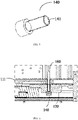
FIG. 1 shows a CT detection device according to an embodiment of the present disclosure; -
FIG. 2 shows a rotating frame according to an embodiment of the present disclosure; -
FIG. 3 shows a support stand according to an embodiment of the present disclosure; -
FIG. 4 shows a first sleeve according to an embodiment of the present disclosure; -
FIG. 5 shows a second sleeve according to an embodiment of the present disclosure; -
FIG. 6 shows a partial cross-sectional view of a CT detection device according to an embodiment of the present disclosure, wherein the CT detection device is in a maintenance state; and -
FIG. 7 shows a partial cross-sectional view of a CT detection device according to an embodiment of the present disclosure, wherein the CT detection device is in a state of replacing a slip ring bearing. - Technical solutions of the present disclosure will be further described in detail through the following embodiments in combination with the accompanying drawings. In the specification, the same or similar reference numerals indicate the same or similar components. The following descriptions of the embodiments of the present disclosure with reference to the accompanying drawings are intended to explain the general inventive concept of the present disclosure, and should not be construed as limiting the present disclosure.
- In addition, in the following detailed descriptions, for ease of explanation, various specific details are set forth in order to provide a comprehensive understanding of the embodiments of the present disclosure. However, it is obvious that one or more embodiments may be implemented without these specific details. In other instances, commonly known structures and devices are shown in diagram to simplify the drawings.
- In an embodiment of the present disclosure, during a maintenance of a CT detection device, two sides of a support stand are respectively provided with a cylindrical pin hole, and a circumference of a rotating frame are provided with several cylindrical pin holes. When the CT imaging system rotates to a suitable position, a cylindrical pin is used to pass through the cylindrical pin hole on the rotating frame and the cylindrical pin hole on the support stand at the same time, so that the rotating frame is fixed on a desired position by using the cylindrical pin. During a replacement of a slip ring bearing, two fixing blocks are mounted on the support stand, and other ends of the fixing blocks are fixed on the rotating frame.
- Although the locking mechanism in the above-mentioned embodiment may achieve a required locking during the maintenance of the CT detection device and the replacement of the slip ring bearing, disadvantages of the above-mentioned solution lie in that a processing workload of the parts is large, a space occupied is large, and a cost is high. As a random accessory, the fixing block is required to be stored for a long time due to few using time, and a space occupied is large during storage due to its large volume.
- Regarding at least one aspect of the above-mentioned defects, another embodiment of the present disclosure provides an improved solution. The present disclosure will be described in more detail below in combination with the accompanying drawings.
- As shown in
FIG. 1 to FIG. 4 , the embodiment of the present disclosure provides aCT detection device 100, including aCT imaging system 110, asupport stand 120 and afirst sleeve 130. TheCT imaging system 110 includes a radiation source, a detector and a rotatingframe 111, and the radiation source and the detector are mounted on the rotatingframe 111. A periphery of the rotatingframe 111 is provided with at least onefirst hole 112. The rotatingframe 111 is fixed on the support stand 120 through a slip ring bearing. A periphery of thesupport stand 120 is provided with at least onesecond hole 122 aligned with the at least onefirst hole 112. When the at least onefirst hole 112 is aligned with the at least onesecond hole 122, thefirst sleeve 130 is detachably engaged in the alignedfirst hole 112 andsecond hole 122. As shown inFIG. 4 andFIG. 7 , thefirst sleeve 130 includes a first cooperatingportion 133, and the first cooperatingportion 133 cooperates with afirst locking portion 150 to lock therotating frame 111 during a replacement of the slip ring bearing. In this way, in the embodiment, a locking of the rotating frame is achieved by using less parts and structures during the replacement of the slip ring bearing, thereby simplifying the maintenance work. - In the embodiment, the radiation source provides a ray of, for example, one or more of an X-ray, a gamma (γ) ray, and a neutron ray, for detecting an object. The radiation source may be, for example, an accelerator, an isotope source, an X-ray machine or the like. In the embodiment, the detector is configured to detect the ray emitted from the radiation source.
- As shown in
FIG. 2 , therotating frame 111 includes a plurality offirst holes 112, and the plurality offirst holes 112 are evenly distributed on the periphery of therotating frame 111. As shown inFIG. 3 , thesupport stand 120 includes anaccommodating cavity 121, and therotating frame 111 is mounted in theaccommodating cavity 121. Thesupport stand 120 includes a plurality ofsecond holes 122, and the plurality ofsecond holes 122 are evenly distributed on a periphery of theaccommodating cavity 121. The examples shown inFIG. 2 andFIG. 3 are only illustrative, and quantities and positions of the first holes and the second holes may be adjusted by those skilled in the art as required. - As shown in
FIG. 4 , thefirst sleeve 130 includes a firstcylindrical portion 131 and a secondcylindrical portion 132. The firstcylindrical portion 131 is engaged with thefirst hole 112, and the secondcylindrical portion 132 is engaged with thesecond hole 122. In the embodiment, an outer surface of the secondcylindrical portion 132 is provided with an external thread, and an inner surface of thesecond hole 122 is provided with an internal thread, so that the secondcylindrical portion 132 cooperates with thesecond hole 122 in a threaded manner. In the embodiment, an outer surface of the firstcylindrical portion 131 is provided with an external thread, and an inner surface of thefirst hole 112 is provided with an internal thread, so that the firstcylindrical portion 131 cooperates with thefirst hole 112 in a threaded manner. An external thread may be provided on one or both of the two cylindrical portions to cooperate with an internal thread in a corresponding hole by those skilled in the art as required. - As shown in
FIG. 4 , a diameter of the firstcylindrical portion 131 is smaller than a diameter of the secondcylindrical portion 132. In the embodiment, thefirst sleeve 130 further includes astep 134 connecting thefirst sleeve portion 131 with thesecond sleeve portion 132. - In the embodiment, an inner surface of the first
cylindrical portion 131 is provided with a thread to form a first cooperatingportion 133, and the first cooperatingportion 133 cooperates with a first locking portion 150 (such as a screw) to lock the rotating frame. In this way, a repositioning of the CT imaging system may be avoided after a new slip ring bearing is mounted, which facilitates subsequent operations. Moreover, in the solution of the present disclosure, the first locking portion having a simple structure and a small volume, such as a screw, is used, which reduces the workload of processing parts and a part space occupied by the locking assembly compared with a fixed block, thereby allowing a reduced dimension of the rotating frame. Those skilled in the art may understand that inner surfaces of both the firstcylindrical portion 131 and the secondcylindrical portion 132 may be provided with threads. Correspondingly, thefirst locking portion 150 cooperates with the threads on the inner surfaces of both the first cylindrical portion and the second cylindrical portion at the same time so as to achieve the locking. A specific providing manner may be selected by those skilled in the art as required. - In the embodiment, when the slip ring bearing is required to be replaced, the
first sleeve 130 is mounted in thefirst hole 112 and thesecond hole 122, then therotating frame 111 is rotated to a proper position. At this time, an end portion of thefirst sleeve 130 is attached to a surface of therotating frame 111 which is located at a normal operation position, and thefirst locking portion 150 cooperates with the first cooperatingportion 133 subsequently to achieve the locking. In this case, the end portion of the first sleeve is formed as a positioning surface to ensure that the position at which the rotating frame is located is the same as the position of its normal operation. - In the embodiment, when the CT detection device is required to be maintained, the first locking portion cooperates with the first cooperating portion, thereby fixing the rotating frame and allowing the rotating frame to be fixed at a position of arbitrary angle. In this way, two sets of locking assemblies used in two situations of replacing the slip ring bearing and maintaining the CT detection device are integrated into one set of locking assembly by the embodiment of the present disclosure, so as to achieve a locking requirement of the CT imaging system in different application scenarios with less parts and structures. Moreover, in the embodiments of the present disclosure, a locking function may be achieved conveniently and quickly, and the parts are small in volume and easy to be stored. Those skilled in the art may understand that another locking portion different from the first locking portion, such as a pin, may also be used when the CT detection device is required to be maintained.
- In the embodiment, the
CT detection device 100 further includes asecond sleeve 140 configured to cooperate with thesecond hole 122. In the embodiment, an outer surface of thesecond sleeve 140 is provided with an external thread, and the inner surface of thesecond hole 122 is provided with an internal thread, so that thesecond sleeve 140 is mounted in thesecond hole 122 in a threaded manner. - As shown in
FIG. 5 , thesecond sleeve 140 includes a second cooperatingportion 141, and the second cooperating portion cooperates with asecond locking portion 160 to lock therotating frame 111 during the maintenance of theCT detection device 100. In the embodiment, a pin hole is formed inside thesecond sleeve 140, and the pin hole forms the second cooperatingportion 141 to cooperate with the second locking portion 160 (such as a pin). As shown inFIG. 6 , the pin is inserted into thefirst hole 112 and the pin hole inside thesecond sleeve 140, so that therotating frame 111 is stopped at a desired position. In the embodiment, inner diameters of the pin hole andfirst hole 112 are substantially equal to an outer diameter of the pin. Those skilled in the art may understand that a threaded hole may be formed inside thesecond sleeve 140, and the threaded hole forms the second cooperating portion to cooperate with the second locking portion (such as a screw). - In the embodiment, the
second sleeve 140 may be located in thesecond hole 122 when theCT detection device 100 operates normally. When theCT detection device 100 is required to be maintained, the second locking portion is inserted into the second cooperating portion to fix therotating frame 111. As shown inFIG. 7 , when the slip ring bearing is required to be replaced, thesecond sleeve 140 is removed from thesecond hole 122, then thefirst sleeve 130 is mounted in thesecond hole 122 and thefirst hole 112, and the first locking portion is mounted subsequently to lock therotating frame 111. In this way, the locking requirement of the CT imaging system in different application scenarios is achieved by the embodiment of the present disclosure with less parts and structures, and the locking function may be achieved conveniently and quickly. - In the embodiments, both the first sleeve and the second sleeve may be formed by transforming screws, for example, by transforming finished hexagonal round heads, so that the cost is reduced and the workload of processing parts is reduced.
- Those skilled in the art may understand that the embodiments described above are exemplary, and those skilled in the art may make improvements on them. The structures described in the various embodiments may be freely combined without structural or principle conflict.
- Although the present disclosure has been described with reference to the accompanying drawings, the embodiments disclosed in the accompanying drawings are intended to illustrate preferred embodiments of the present disclosure, and should not be construed as limiting the present disclosure.
- Although some embodiments of the general inventive concept of the present disclosure have been shown and described, those of ordinary skill in the art will understand that modifications may be made to these embodiments without departing from the principle and spirit of the general inventive concept of the present disclosure, and the scope of the present disclosure is defined by the claims and their equivalents.
- It should be noted that the wording "include" does not exclude other elements or steps, and the wording "a" or "an" does not exclude a plurality. In addition, any reference numeral in the claims should not be construed as limiting the scope of the present disclosure.
Claims (20)
- A CT detection device, comprising:a CT imaging system, comprising a radiation source, a detector, and a rotating frame, wherein the radiation source and the detector are mounted on the rotating frame, and a periphery of the rotating frame is provided with at least one first hole;a support stand, wherein the rotating frame is fixed on the support stand through a slip ring bearing, and a periphery of the support stand is provided with at least one second hole aligned with the at least one first hole; anda first sleeve detachably engaged in the aligned first hole and second hole, wherein the first sleeve comprises a first cooperating portion, and the first cooperating portion cooperates with a first locking portion to lock the rotating frame during a replacement of the slip ring bearing.
- The CT detection device according to claim 1, wherein the first sleeve comprises a first cylindrical portion engaged with the first hole and a second cylindrical portion engaged with the second hole,wherein an outer surface of the first cylindrical portion and an inner surface of the first hole are provided with threads; and/oran outer surface of the second cylindrical portion and an inner surface of the second hole are provided with threads.
- The CT detection device according to claim 2, wherein a diameter of the first cylindrical portion is smaller than a diameter of the second cylindrical portion, and the first cylindrical portion is connected with the second cylindrical portion by a step; and
wherein a diameter of the first hole is smaller than a diameter of the second hole. - The CT detection apparatus according to claim 2, wherein the first cooperating portion is formed as a thread on an inner surface of the first cylindrical portion or as threads on inner surfaces of the first cylindrical portion and the second cylindrical portion, and the first locking portion is formed as a screw
- The CT detection device according to claim 1, wherein,the at least one first hole comprises a plurality of first holes evenly distributed on the periphery of the rotating frame; andthe at least one second hole comprises a plurality of second holes evenly distributed on a periphery of an accommodating cavity of the support stand, and the rotating frame is mounted in the accommodating cavity.
- The CT detection device according to claim 1, wherein an end surface of an end of the first sleeve is a positioning surface.
- The CT detection device according to any one of claims 1-6, further comprising a second sleeve configured to be detachably engaged in the second hole in a case that the first sleeve is removed from the first hole and the second hole, the second sleeve further comprising a second cooperating portion, wherein the second cooperating portion and the first hole cooperate with a second locking portion to lock the rotating frame during a maintenance of the CT detection device.
- The CT detection device according to claim 7, wherein an outer surface of the second sleeve and an inner surface of the second hole comprise threads.
- The CT detection device according to claim 8, wherein the second cooperating portion is formed as a pin hole inside the second sleeve, the second locking portion is formed as a pin, and the pin is inserted into the first hole and the pin hole inside the second sleeve.
- The CT detection device according to claim 9, wherein inner diameters of the pin hole and the first hole are substantially equal to an outer diameter of the pin.
- The CT detection device according to claim 2, wherein the first cooperating portion is formed as a thread on the inner surface of the first cylindrical portion or as threads on inner surfaces of the first cylindrical portion and the second cylindrical portion, the first locking portion is formed as a pin, and the pin is inserted into the first hole and the first cooperating portion to lock the rotating frame during a maintenance of the CT detection device.
- A locking assembly for a CT detection device, the CT detection device comprising a support stand and a rotating frame of a CT imaging system fixed together by a slip ring bearing, wherein the locking assembly comprises:at least one first hole provided on the rotating frame;at least one second hole provided on the support stand, wherein the at least one second hole is configured to be aligned with the at least one first hole;a first sleeve detachably engaged in the aligned first hole and second hole, wherein the first sleeve comprises a first cooperating portion; anda first locking portion cooperating with the first cooperating portion to lock the rotating frame during a replacement of the slip ring bearing.
- The locking assembly according to claim 12, wherein the first sleeve further comprises a first cylindrical portion engaged with the first hole and a second cylindrical portion engaged with the second hole,wherein an outer surface of the first cylindrical portion and an inner surface of the first hole are provided with threads; and/oran outer surface of the second cylindrical portion and an inner surface of the second hole are provided with threads.
- The locking assembly according to claim 13, wherein a diameter of the first cylindrical portion is smaller than a diameter of the second cylindrical portion, and the first cylindrical portion is connected with the second cylindrical portion by a step; and
wherein a diameter of the first hole is smaller than a diameter of the second hole. - The locking assembly according to claim 13, wherein the first cooperating portion is formed as a thread on an inner surface of the first cylindrical portion or as threads on inner surfaces of the first cylindrical portion and the second cylindrical portion, the first locking portion is formed as a screw, and an end surface of an end portion of the first sleeve is a positioning surface.
- The locking assembly according to claim 12, wherein,the at least one first hole comprises a plurality of first holes evenly distributed on a periphery of the rotating frame; andthe at least one second hole comprises a plurality of second holes evenly distributed on a periphery of an accommodating cavity of the support stand, and the rotating frame is mounted in the accommodating cavity.
- The locking assembly according to any one of claims 12-16, further comprising a second sleeve configured to be detachably engaged in the second hole in a case that the first sleeve is removed from the first hole and the second hole, the second sleeve comprises a second cooperating portion, wherein the second cooperating portion and the first hole cooperate with a second locking portion to lock the rotating frame during a maintenance of the CT detection device.
- The locking assembly according to claim 17, wherein an outer surface of the second sleeve and the inner surface of the second hole comprise threads.
- The locking assembly according to claim 17, wherein the second cooperating portion is formed as a pin hole inside the second sleeve, the second locking portion is formed as a pin, the pin is inserted into the first hole and the pin hole inside the second sleeve, and inner diameters of the pin hole and the first hole are substantially equal to an outer diameter of the pin.
- The locking assembly according to claim 13, wherein the first cooperating portion is formed as a thread on the inner surface of the first cylindrical portion or as threads on inner surfaces of the first cylindrical portion and the second cylindrical portion, the first locking portion is formed as a pin, and the pin is inserted into the first hole and the first cooperating portion to lock the rotating frame during a maintenance of the CT detection device.
Applications Claiming Priority (2)
| Application Number | Priority Date | Filing Date | Title |
|---|---|---|---|
| CN202010473343.5A CN113740363B (en) | 2020-05-29 | 2020-05-29 | Locking assembly for CT detection device and CT detection device |
| PCT/CN2021/094357 WO2021238720A1 (en) | 2020-05-29 | 2021-05-18 | Locking assembly for ct detection device, and ct detection device |
Publications (3)
| Publication Number | Publication Date |
|---|---|
| EP4159134A1 true EP4159134A1 (en) | 2023-04-05 |
| EP4159134A4 EP4159134A4 (en) | 2024-07-17 |
| EP4159134B1 EP4159134B1 (en) | 2025-07-02 |
Family
ID=78724499
Family Applications (1)
| Application Number | Title | Priority Date | Filing Date |
|---|---|---|---|
| EP21812364.4A Active EP4159134B1 (en) | 2020-05-29 | 2021-05-18 | Locking assembly for ct detection device, and ct detection device |
Country Status (4)
| Country | Link |
|---|---|
| EP (1) | EP4159134B1 (en) |
| JP (1) | JP7518211B2 (en) |
| CN (1) | CN113740363B (en) |
| WO (1) | WO2021238720A1 (en) |
Families Citing this family (3)
| Publication number | Priority date | Publication date | Assignee | Title |
|---|---|---|---|---|
| CN119949863A (en) * | 2025-04-11 | 2025-05-09 | 安络杰医疗器械(上海)有限公司 | CT scanning frame and CT scanning device |
| CN120167987B (en) * | 2025-04-17 | 2025-10-03 | 安络杰医疗器械(上海)有限公司 | A large-caliber CT scanning device |
| CN120742434B (en) * | 2025-08-21 | 2025-12-05 | 上海物影科技有限公司 | Stator system capable of realizing spiral CT scanning |
Family Cites Families (16)
| Publication number | Priority date | Publication date | Assignee | Title |
|---|---|---|---|---|
| JP4406101B2 (en) * | 1998-10-16 | 2010-01-27 | 株式会社東芝 | X-ray CT system |
| CN201785529U (en) * | 2010-07-12 | 2011-04-06 | 中国电子科技集团公司第二研究所 | Adjusting mechanism for material sheet baffles of feeding and unloading machine |
| JP2013167347A (en) * | 2012-02-17 | 2013-08-29 | Bastem:Kk | Fastening device using insert screw |
| CN103089788B (en) * | 2013-02-04 | 2015-09-30 | 慈溪市附海大奇电器厂 | A kind of outer drawing type self-locking screw |
| CN203576528U (en) * | 2013-09-29 | 2014-05-07 | 上海西门子医疗器械有限公司 | CT (computed tomography) gantry component and CT machine |
| US9492127B2 (en) * | 2014-01-27 | 2016-11-15 | Epica International, Inc. | Radiological imaging device with adjustable bed |
| US10039505B2 (en) * | 2014-07-22 | 2018-08-07 | Samsung Electronics Co., Ltd. | Anatomical imaging system having fixed gantry and rotating disc, with adjustable angle of tilt and increased structural integrity, and with improved power transmission and position sensing |
| JP6382673B2 (en) * | 2014-10-06 | 2018-08-29 | ナックス株式会社 | Fastener |
| WO2016199530A1 (en) * | 2015-06-09 | 2016-12-15 | 株式会社日立製作所 | X-ray ct device and bearing replacement method |
| DE102016204006B4 (en) * | 2016-03-11 | 2025-06-18 | Siemens Healthineers Ag | Arrangement with a stationary part and a first rotating part of a gantry of a computed tomography device and method for maintaining a component of a gantry of a computed tomography device |
| CN105626658A (en) * | 2016-03-26 | 2016-06-01 | 华为技术有限公司 | Self-locking anti-loosening fastening piece, fastening device and fastening structure |
| KR20180077989A (en) * | 2016-12-29 | 2018-07-09 | 삼성전자주식회사 | Medical device |
| EP3609407A1 (en) * | 2017-04-14 | 2020-02-19 | Analogic Corporation | Wheel and lift unit for radiation imaging modalities |
| CN107714064B (en) * | 2017-09-28 | 2021-12-31 | 北京东软医疗设备有限公司 | Imaging device and medical apparatus |
| CN208931962U (en) * | 2018-09-20 | 2019-06-04 | 明峰医疗系统股份有限公司 | A kind of CT locked rotor support construction |
| US10881362B2 (en) * | 2018-11-20 | 2021-01-05 | General Electric Company | Systems for laser alignment |
-
2020
- 2020-05-29 CN CN202010473343.5A patent/CN113740363B/en active Active
-
2021
- 2021-05-18 WO PCT/CN2021/094357 patent/WO2021238720A1/en not_active Ceased
- 2021-05-18 JP JP2022573617A patent/JP7518211B2/en active Active
- 2021-05-18 EP EP21812364.4A patent/EP4159134B1/en active Active
Also Published As
| Publication number | Publication date |
|---|---|
| CN113740363B (en) | 2022-08-26 |
| CN113740363A (en) | 2021-12-03 |
| EP4159134A4 (en) | 2024-07-17 |
| JP7518211B2 (en) | 2024-07-17 |
| EP4159134B1 (en) | 2025-07-02 |
| WO2021238720A1 (en) | 2021-12-02 |
| JP2023527241A (en) | 2023-06-27 |
Similar Documents
| Publication | Publication Date | Title |
|---|---|---|
| EP4159134B1 (en) | Locking assembly for ct detection device, and ct detection device | |
| US10722197B2 (en) | Arrangement with a stationary part and a first rotating part of a gantry of a computed tomography scanner and method for maintaining a component of a gantry of a computed tomography scanner | |
| US10219760B2 (en) | Rotary member with safety mechanism | |
| HK40087340A (en) | Locking assembly for ct detection device, and ct detection device | |
| HK40087340B (en) | Locking assembly for ct detection device, and ct detection device | |
| CN110017928B (en) | Automatic clamp for testing motor torque of stepping motor | |
| CN217056166U (en) | Gear center distance adjusting device | |
| US11279010B2 (en) | Hub holding apparatus | |
| CN111185876B (en) | A space station orbit maintenance tool | |
| US2876363A (en) | Radiation projector and charge handling means therefor | |
| US3574365A (en) | Lock for detachably mounting a tape reel hub to a drive shaft | |
| CN106333704A (en) | PET rack | |
| CN115815949B (en) | A fixing device for pipe parts and a method for fixing pipe parts | |
| JPH1071531A (en) | Remote lock tool for bolt | |
| CN116493989A (en) | Turning fixture for master cylinder hole of automobile hydraulic caliper disc brake caliper | |
| CN218922611U (en) | Turntable of medical imaging system, rack of CT machine, CT machine and medical imaging system | |
| CN212434821U (en) | Antenna rotation installation mechanism | |
| CN211920408U (en) | Portable grounding wire take-up device | |
| CN215364179U (en) | Fixing device of steel wire outlet spindle | |
| CN219549394U (en) | Bearing easy to fix | |
| CN207558047U (en) | A kind of angle adjustment mechanism and automobile data recorder | |
| CN216686962U (en) | Chip lead frame automated production curb plate subassembly for reel | |
| JP2020009635A (en) | Lug terminal connection mechanism | |
| CN117055276B (en) | Lens structure and camera | |
| US2469993A (en) | Locking device |
Legal Events
| Date | Code | Title | Description |
|---|---|---|---|
| STAA | Information on the status of an ep patent application or granted ep patent |
Free format text: STATUS: THE INTERNATIONAL PUBLICATION HAS BEEN MADE |
|
| PUAI | Public reference made under article 153(3) epc to a published international application that has entered the european phase |
Free format text: ORIGINAL CODE: 0009012 |
|
| STAA | Information on the status of an ep patent application or granted ep patent |
Free format text: STATUS: REQUEST FOR EXAMINATION WAS MADE |
|
| 17P | Request for examination filed |
Effective date: 20221219 |
|
| AK | Designated contracting states |
Kind code of ref document: A1 Designated state(s): AL AT BE BG CH CY CZ DE DK EE ES FI FR GB GR HR HU IE IS IT LI LT LU LV MC MK MT NL NO PL PT RO RS SE SI SK SM TR |
|
| DAV | Request for validation of the european patent (deleted) | ||
| DAX | Request for extension of the european patent (deleted) | ||
| REG | Reference to a national code |
Ref country code: HK Ref legal event code: DE Ref document number: 40087340 Country of ref document: HK |
|
| A4 | Supplementary search report drawn up and despatched |
Effective date: 20240613 |
|
| RIC1 | Information provided on ipc code assigned before grant |
Ipc: G01N 23/046 20180101ALI20240610BHEP Ipc: A61B 6/03 20060101AFI20240610BHEP |
|
| GRAP | Despatch of communication of intention to grant a patent |
Free format text: ORIGINAL CODE: EPIDOSNIGR1 |
|
| STAA | Information on the status of an ep patent application or granted ep patent |
Free format text: STATUS: GRANT OF PATENT IS INTENDED |
|
| RIC1 | Information provided on ipc code assigned before grant |
Ipc: G01N 23/046 20180101ALI20241219BHEP Ipc: A61B 6/03 20060101AFI20241219BHEP |
|
| INTG | Intention to grant announced |
Effective date: 20250122 |
|
| GRAS | Grant fee paid |
Free format text: ORIGINAL CODE: EPIDOSNIGR3 |
|
| GRAA | (expected) grant |
Free format text: ORIGINAL CODE: 0009210 |
|
| STAA | Information on the status of an ep patent application or granted ep patent |
Free format text: STATUS: THE PATENT HAS BEEN GRANTED |
|
| AK | Designated contracting states |
Kind code of ref document: B1 Designated state(s): AL AT BE BG CH CY CZ DE DK EE ES FI FR GB GR HR HU IE IS IT LI LT LU LV MC MK MT NL NO PL PT RO RS SE SI SK SM TR |
|
| REG | Reference to a national code |
Ref country code: GB Ref legal event code: FG4D |
|
| REG | Reference to a national code |
Ref country code: CH Ref legal event code: EP |
|
| REG | Reference to a national code |
Ref country code: DE Ref legal event code: R096 Ref document number: 602021033492 Country of ref document: DE |
|
| REG | Reference to a national code |
Ref country code: IE Ref legal event code: FG4D |
|
| REG | Reference to a national code |
Ref country code: NL Ref legal event code: MP Effective date: 20250702 |
|
| PG25 | Lapsed in a contracting state [announced via postgrant information from national office to epo] |
Ref country code: PT Free format text: LAPSE BECAUSE OF FAILURE TO SUBMIT A TRANSLATION OF THE DESCRIPTION OR TO PAY THE FEE WITHIN THE PRESCRIBED TIME-LIMIT Effective date: 20251103 |
|
| PG25 | Lapsed in a contracting state [announced via postgrant information from national office to epo] |
Ref country code: NL Free format text: LAPSE BECAUSE OF FAILURE TO SUBMIT A TRANSLATION OF THE DESCRIPTION OR TO PAY THE FEE WITHIN THE PRESCRIBED TIME-LIMIT Effective date: 20250702 |
|
| REG | Reference to a national code |
Ref country code: AT Ref legal event code: MK05 Ref document number: 1808318 Country of ref document: AT Kind code of ref document: T Effective date: 20250702 |
|
| PG25 | Lapsed in a contracting state [announced via postgrant information from national office to epo] |
Ref country code: IS Free format text: LAPSE BECAUSE OF FAILURE TO SUBMIT A TRANSLATION OF THE DESCRIPTION OR TO PAY THE FEE WITHIN THE PRESCRIBED TIME-LIMIT Effective date: 20251102 |
|
| PG25 | Lapsed in a contracting state [announced via postgrant information from national office to epo] |
Ref country code: NO Free format text: LAPSE BECAUSE OF FAILURE TO SUBMIT A TRANSLATION OF THE DESCRIPTION OR TO PAY THE FEE WITHIN THE PRESCRIBED TIME-LIMIT Effective date: 20251002 |
|
| REG | Reference to a national code |
Ref country code: LT Ref legal event code: MG9D |
|
| PG25 | Lapsed in a contracting state [announced via postgrant information from national office to epo] |
Ref country code: AT Free format text: LAPSE BECAUSE OF FAILURE TO SUBMIT A TRANSLATION OF THE DESCRIPTION OR TO PAY THE FEE WITHIN THE PRESCRIBED TIME-LIMIT Effective date: 20250702 |
|
| PG25 | Lapsed in a contracting state [announced via postgrant information from national office to epo] |
Ref country code: FI Free format text: LAPSE BECAUSE OF FAILURE TO SUBMIT A TRANSLATION OF THE DESCRIPTION OR TO PAY THE FEE WITHIN THE PRESCRIBED TIME-LIMIT Effective date: 20250702 |
|
| PG25 | Lapsed in a contracting state [announced via postgrant information from national office to epo] |
Ref country code: HR Free format text: LAPSE BECAUSE OF FAILURE TO SUBMIT A TRANSLATION OF THE DESCRIPTION OR TO PAY THE FEE WITHIN THE PRESCRIBED TIME-LIMIT Effective date: 20250702 |
|
| PG25 | Lapsed in a contracting state [announced via postgrant information from national office to epo] |
Ref country code: GR Free format text: LAPSE BECAUSE OF FAILURE TO SUBMIT A TRANSLATION OF THE DESCRIPTION OR TO PAY THE FEE WITHIN THE PRESCRIBED TIME-LIMIT Effective date: 20251003 |
|
| PG25 | Lapsed in a contracting state [announced via postgrant information from national office to epo] |
Ref country code: CZ Free format text: LAPSE BECAUSE OF FAILURE TO SUBMIT A TRANSLATION OF THE DESCRIPTION OR TO PAY THE FEE WITHIN THE PRESCRIBED TIME-LIMIT Effective date: 20250702 Ref country code: SE Free format text: LAPSE BECAUSE OF FAILURE TO SUBMIT A TRANSLATION OF THE DESCRIPTION OR TO PAY THE FEE WITHIN THE PRESCRIBED TIME-LIMIT Effective date: 20250702 |
|
| PG25 | Lapsed in a contracting state [announced via postgrant information from national office to epo] |
Ref country code: LV Free format text: LAPSE BECAUSE OF FAILURE TO SUBMIT A TRANSLATION OF THE DESCRIPTION OR TO PAY THE FEE WITHIN THE PRESCRIBED TIME-LIMIT Effective date: 20250702 |
|
| PG25 | Lapsed in a contracting state [announced via postgrant information from national office to epo] |
Ref country code: BG Free format text: LAPSE BECAUSE OF FAILURE TO SUBMIT A TRANSLATION OF THE DESCRIPTION OR TO PAY THE FEE WITHIN THE PRESCRIBED TIME-LIMIT Effective date: 20250702 Ref country code: PL Free format text: LAPSE BECAUSE OF FAILURE TO SUBMIT A TRANSLATION OF THE DESCRIPTION OR TO PAY THE FEE WITHIN THE PRESCRIBED TIME-LIMIT Effective date: 20250702 |
|
| PG25 | Lapsed in a contracting state [announced via postgrant information from national office to epo] |
Ref country code: RS Free format text: LAPSE BECAUSE OF FAILURE TO SUBMIT A TRANSLATION OF THE DESCRIPTION OR TO PAY THE FEE WITHIN THE PRESCRIBED TIME-LIMIT Effective date: 20251002 |
|
| PG25 | Lapsed in a contracting state [announced via postgrant information from national office to epo] |
Ref country code: ES Free format text: LAPSE BECAUSE OF FAILURE TO SUBMIT A TRANSLATION OF THE DESCRIPTION OR TO PAY THE FEE WITHIN THE PRESCRIBED TIME-LIMIT Effective date: 20250702 |
|
| PG25 | Lapsed in a contracting state [announced via postgrant information from national office to epo] |
Ref country code: SM Free format text: LAPSE BECAUSE OF FAILURE TO SUBMIT A TRANSLATION OF THE DESCRIPTION OR TO PAY THE FEE WITHIN THE PRESCRIBED TIME-LIMIT Effective date: 20250702 |
|
| PG25 | Lapsed in a contracting state [announced via postgrant information from national office to epo] |
Ref country code: DK Free format text: LAPSE BECAUSE OF FAILURE TO SUBMIT A TRANSLATION OF THE DESCRIPTION OR TO PAY THE FEE WITHIN THE PRESCRIBED TIME-LIMIT Effective date: 20250702 |
|
| PG25 | Lapsed in a contracting state [announced via postgrant information from national office to epo] |
Ref country code: IT Free format text: LAPSE BECAUSE OF FAILURE TO SUBMIT A TRANSLATION OF THE DESCRIPTION OR TO PAY THE FEE WITHIN THE PRESCRIBED TIME-LIMIT Effective date: 20250702 |
|
| PG25 | Lapsed in a contracting state [announced via postgrant information from national office to epo] |
Ref country code: EE Free format text: LAPSE BECAUSE OF FAILURE TO SUBMIT A TRANSLATION OF THE DESCRIPTION OR TO PAY THE FEE WITHIN THE PRESCRIBED TIME-LIMIT Effective date: 20250702 Ref country code: SK Free format text: LAPSE BECAUSE OF FAILURE TO SUBMIT A TRANSLATION OF THE DESCRIPTION OR TO PAY THE FEE WITHIN THE PRESCRIBED TIME-LIMIT Effective date: 20250702 |
|
| PLBE | No opposition filed within time limit |
Free format text: ORIGINAL CODE: 0009261 |
|
| STAA | Information on the status of an ep patent application or granted ep patent |
Free format text: STATUS: NO OPPOSITION FILED WITHIN TIME LIMIT |