EP4159072A1 - Mask - Google Patents
Mask Download PDFInfo
- Publication number
- EP4159072A1 EP4159072A1 EP21812960.9A EP21812960A EP4159072A1 EP 4159072 A1 EP4159072 A1 EP 4159072A1 EP 21812960 A EP21812960 A EP 21812960A EP 4159072 A1 EP4159072 A1 EP 4159072A1
- Authority
- EP
- European Patent Office
- Prior art keywords
- ear
- materials
- mask
- horizontal direction
- constituting
- Prior art date
- Legal status (The legal status is an assumption and is not a legal conclusion. Google has not performed a legal analysis and makes no representation as to the accuracy of the status listed.)
- Granted
Links
Images






Classifications
-
- A—HUMAN NECESSITIES
- A41—WEARING APPAREL
- A41D—OUTERWEAR; PROTECTIVE GARMENTS; ACCESSORIES
- A41D13/00—Professional, industrial or sporting protective garments, e.g. surgeons' gowns or garments protecting against blows or punches
- A41D13/05—Professional, industrial or sporting protective garments, e.g. surgeons' gowns or garments protecting against blows or punches protecting only a particular body part
- A41D13/11—Protective face masks, e.g. for surgical use, or for use in foul atmospheres
- A41D13/1161—Means for fastening to the user's head
Definitions
- the present invention relates to a mask.
- a known configuration of a mask to be worn on the face includes: a mask body that at least partially covers the face of a wearer; and ear materials (or ear hooks), constituting a pair, each being coupled to the mask body, i.e., a pair of members that can be hung on the ears of the wearer in order to hold the mask body at a predetermined position.
- PTL 1 discloses a mask that includes a mask body portion and ear hook portions connected to the mask body portion, wherein the ear hook portions are connected to respective end portion areas, and the ear hook portions connected to the respective end portion areas of the body are configured to be accommodated within the outer shape of the mask body in a plan view of the mask, and the mask includes a connection portion that connects the ear hook portions to each other within the outer shape of the mask body.
- connection portions between the ear hook portions and the mask body might be damaged when the ear hook portions are separated and opened. It is also possible to harden the connection portions in order to form strong bonding, but the flexibility of the mask may be lost, and discomfort may occur when the connection portions come into contact with the skin.
- a mask body ear materials, constituting a pair, coupled to the mask body; and auxiliary materials provided on an outer surface side of the mask body, wherein in a state before start of use, the ear materials, constituting the pair, are separably coupled with each other, and provided on the outer surface side of the mask body, outlines of the ear materials have a wavy shape, and the ear materials, constituting the pair, are coupled to an outer surface in side portions of the mask body via the auxiliary materials.
- a robust mask with good fit can be provided.
- a mask according to an embodiment of the present invention may be a mask capable of covering the face of a wearer, more specifically, covering at least the nose and the mouth of a wearer.
- the mask according to this embodiment can have a function of preventing foreign matter from reaching the face and preventing droplets generated by the wearer from being scattered, and is also referred to as a sanitary mask or surgical mask.
- the mask may be disposable or reusable by washing.
- FIG. 1 is a plan view of a mask 100 according to the present embodiment.
- FIG. 1 is a view of the mask 100 as seen from the outside, i.e., from the side exposed to the outside and facing away from the face when the mask 100 is worn.
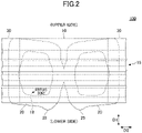
- FIG. 2 is a plan view of the mask as seen from the inside (face side).
- the mask 100 includes: a mask body (which may be simply referred to as a body) 10 which is disposed in front of the face of the wearer when the mask is worn and can mainly cover the nose and mouth of the wearer; and ear materials 20, 20, constituting the pair, coupled to the mask body 10.
- the mask body 10 has a vertical direction D1 corresponding to the height direction of the wearer's face when wearing the mask and a horizontal direction D2 orthogonal to the vertical direction D1.
- the mask body 10 has a rectangular shape in a plan view having long sides in the horizontal direction D2, but the shape of the mask body 10 in a plan view is not limited to the shape as illustrated in the drawings.
- the mask body 10 has a pleated structure 15 formed by multiple pleats arranged side by side in the vertical direction D1.
- the pleats of the pleated structure 15 are formed by folding a sheet constituting the body 10 at fold lines along the horizontal direction D2.
- the side portions (the ends in the horizontal direction D2) of the mask body 10 are joined and fixed. Therefore, when the mask 100 is used, the pleats of the pleated structure 15 are extended in the vertical direction D1, so that the center in the horizontal direction D2 is curved so as to protrude toward the outer surface side of the mask 100, and can be deformed into a shape adapted to the three-dimensional shape of the face.
- the specific configuration of the pleated structure 15 is not particularly limited and may be a conventional configuration formed in a mask body.
- each ear member 20 may be in an annular shape, or may have a shape that includes an annulus in a plan view.
- the ear materials 20 can be hung on the ears by allowing the ears of the wearer to enter the inside of the ring of each ear material 20, i.e., an opening 29 at the center of each ear material 20.
- the outline of the ring of the ear material 20 may have a wavy shape or an uneven shape.
- the wavy shape may be provided on at least one of the inner outline and the outer outline of the ring, but is preferably provided on at least the inner outline.
- the wavy shape does not have to be provided on the entire outline of the ring of the ear material 20, and it is preferable that, for example, the wavy shape is formed in a portion of the ear material that is in contact with the ear when the mask 100 is worn, i.e., a portion of the ear material 20 that is situated near the center of the mask 100 in the horizontal direction D2 before the start of use.
- the protruding portion included in the wavy shape is easily moved independently, so that the ear material 20 is easily fitted to the shape of the ear, and the ear material 20 can be stably disposed behind the ear when the mask is worn.
- the ear materials 20, 20, constituting the pair may be configured as a continuous sheet separably coupled to each other at the center in the horizontal direction D2.
- the type of coupling at a separable coupling portion 28 between the ear materials 20, 20 constituting the pair is not particularly limited, but is preferably separable by pulling with a usual force of the user. For example, it may be formed as perforations as illustrated in FIG. 1 .
- the coupling portion 28 may also be formed by reducing the thickness of the sheet or by other means to weaken the border between the ear materials 20, 20 constituting the pair or to increase stress.
- the ear materials 20, 20 constituting the pair may be formed independently of each other, slightly overlapping at the center in the horizontal direction D2, and separably coupled by an adhesive, heat sealing, or the like to form the coupling portion 28.
- the mask body 10 may have a multilayer structure formed by laminating multiple layers.
- the structure may include at least three layers sandwiched between an outer layer and an inner layer of an intermediate layer having an enhanced function of collecting foreign matter (dust, pollen, bacteria, viruses, and the like).
- Each layer constituting the body 10 may include a fiber-containing layer such as a nonwoven fabric, a woven fabric, a knitted fabric, and the like, and preferably includes a nonwoven fabric.
- the nonwoven fabric include a spunbond nonwoven fabric, a spunlace nonwoven fabric, a meltblown nonwoven fabric, an air through nonwoven fabric, a point bond nonwoven fabric, and the like.
- a meltblown nonwoven fabric which can contain fine fibers is preferably used for the intermediate layer.
- the fibers constituting the fiber-containing layer are preferably resin fibers, and the resin types of the resin fibers include polyethylene, polypropylene, polyethylene terephthalate, nylon, and the like.
- the basis weight of the outer and inner layers may be 10 to 50 g/m 2 , preferably 15 to 50 g/m 2 .
- the basis weight of the intermediate layer having a high foreign matter collecting property is preferably 10 to 100 g/m 2 and more preferably 15 to 50 g/m 2 .
- the ear materials 20 may be formed of a material having stretchability, preferably a material having higher stretchability than the body 10.
- the ear material 20 may have stretchability at least in the horizontal direction D2, and may have stretchability in both the vertical direction D1 and the horizontal direction D2.
- the stretchability in the vertical direction D1 and the stretchability in the horizontal direction D2 may be the same or different from each other.
- the stretchability in the vertical direction D1 is different from the stretchability in the horizontal direction D2
- it is preferable that the stretchability in the horizontal direction D2 is higher than the stretchability in the horizontal direction D2 of the body 10.
- the ear materials 20 When worn, the ear materials 20 are hung on the ears of the wearer, and are pulled mainly in the horizontal direction D2. Therefore, by having stretchability at least in the horizontal direction D2, the body 10 can be better positioned and fixed in the front of the face, and the load of the ear materials 20 applied to the ears can be reduced.
- the ear material 20 may include a stretchable fiber-containing sheet and/or may include a stretchable or elastic film.
- the fiber-containing sheet includes a nonwoven fabric, a woven fabric, a knitted fabric, and the like, and among these, a nonwoven fabric is preferably used because of its good touch and breathability.
- nonwoven fabric include an air-through nonwoven fabric, a spunbond nonwoven fabric, a spunlace nonwoven fabric, a needle punch nonwoven fabric, a chemical bond nonwoven fabric, and the like.
- the fibers contained in the nonwoven fabric are preferably resin fibers, and the resin types of the resin fibers include polyethylene, polypropylene, polyethylene terephthalate, nylon, and the like.
- the ear materials 20 may contain a single layer of the above stretchable fiber-containing sheet or stretchable film, or may be constituted by laminating multiple layers of the above stretchable fiber-containing sheets and/or stretchable films by laminating the fiber-containing sheets and the stretchable films.
- the stretchability may be exhibited by the stretchable fibers contained in the fiber-containing sheet, for example, by the material of the fibers having stretchability or the fibers being crimped fibers.
- the stretchability may be exhibited by a predetermined physical structure, for example, by having irregularities on the surface.
- the ear materials 20 may be formed by sandwiching a thread-like rubber with a fiber-containing sheet having stretchability or not having stretchability. When the stretchability of the fiber-containing sheet is low or is not provided, the fiber-containing sheets may be attached to both sides while the thread-like rubber is stretched.
- the ear materials 20 may be made of a single-layer nonwoven fabric such as a stretchable air-through nonwoven fabric, a stretchable spunbond nonwoven fabric, a stretchable spunlace nonwoven fabric, a stretchable needle punch nonwoven fabric, a stretchable chemical bond nonwoven fabric, or the like.
- a material including multiple layers of nonwoven fabric such as spunbond/melt blown/spunbond may be used.
- a laminated sheet such as a nonwoven fabric/stretchable film or a nonwoven fabric/stretchable film/nonwoven fabric (for example, spunbond/stretchable film/spunbond, air-through/stretchable film/air-through, and the like) can be used.
- the layers may be bonded to each other with a stretchable or non-stretchable hot-melt nonwoven fabric (a nonwoven fabric whose fibers are softened or melted by heating and can be bonded to other members).
- the basis weight of the ear materials 20 may be 20 to 150 g/m 2 .
- the ear materials 20 may have a thickness of 100 to 3,000 ⁇ m.
- the ear materials 20, 20, constituting the pair are coupled to respective side portions (end portions in the horizontal direction D2) of the outer surface of the body 10. Specifically, the ear materials 20, 20, constituting the pair, are coupled to both side portions of the body 10 via auxiliary materials 30, 30 (the auxiliary materials are explained later in detail). Specifically, the outer portions of the ear materials 20, 20, constituting the pair, in the horizontal direction D2 are coupled to the body 10, and the other portions are not coupled to the body 10.
- the separable coupling between the ear materials 20, 20 constituting the pair is released to separate the ear materials 20, 20 from each other (also referred to as separation operation), and the portions of the ear materials 20, 20 which are not coupled to the body 10 are opened sideways in the horizontal direction D2 (also referred to as an expansion operation).
- separation operation also referred to as separation operation
- expansion operation also referred to as an expansion operation
- FIG. 3 illustrates a state in which the mask 100 illustrated in FIG. 1 is about to be used.
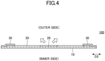
- FIG. 4 is a cross-sectional view taken along line I-I of FIG. 3 .
- the user can pull the ear materials 20, 20 constituting the pair in the opposite directions by pinching or holding them with their respective hands as illustrated in FIG. 3 .
- the separable coupling portion 28 can be first uncoupled. If the coupling portion 28 includes perforations formed along the border line between the ear materials 20, 20 constituting the pair, the perforations can be broken to separate the ear materials 20, 20 along the border line. Thereafter, the user can open the ear materials 20, 20 constituting the pair outward in the horizontal direction D2 toward the sides indicated by the arrows in FIGs. 3 and 4 while holding them.
- FIG. 5 illustrates a state in which the ear materials 20, 20 constituting the pair are opened outward in the horizontal direction D2 from the state illustrated in FIG. 3 .
- FIG. 6 is a cross-sectional view taken along line II-II of FIG. 5 .
- the ear materials 20, 20 constituting the pair are opened, the ear materials 20, 20 are turned over so that the surface facing the body 10 in the state before start of use is exposed.
- the ear materials 20, 20 are mainly disposed on the outer sides in the horizontal direction D2 of the body 10, and the entire outer surface of the body 10 is exposed.
- the mask 100 when the user opens, outward in the horizontal direction D2, the tab portions 25, 25 of the ear materials 20, 20, respectively, constituting the pair as described above by holding the tab portions 25, 25 and then lifting the mask 100, for example, the outer surface of the mask 100 faces the user opening the ear materials 20, 20, and the inner surface of the mask 100 (surface on face side) faces the side away from the user. Therefore, the mask 100 according to the present embodiment is suitable for being worn by another wearer. For example, while the mask 100 is placed with the outside of the mask 100 facing upward (with the outer surface of the body 10 facing upward), the user opens the ear materials 20, 20, constituting the pair, outwardly in the horizontal direction D2 by holding them with hands.
- the mask 100 is moved to the face of another wearer while the ear materials 20, 20 constituting the pair are held, and the mask body 10 is arranged at a desired position of the wearer's face, and at this occasion, the ear materials 20, 20 constituting the pair can be hung on the ears of the wearer while the way of holding the mask 100 is not changed. Therefore, the mask 100 according to the present embodiment can be suitably used when the mask is worn by a person who has difficulty wearing the mask by himself or herself, such as a child or a sick person.
- the ear materials 20, 20 constituting the pair are disposed on the outer surface of the body 10 as described above, the possibility of the user's hand touching the inside of the mask 100 can be reduced or eliminated when the ear materials 20, 20 constituting the pair are separated from each other and opened outward in the horizontal direction D2. Therefore, the expansion operation of the ear materials 20, 20 in the preparation stage before the mask 100 is worn can be performed hygienically.
- the ear materials 20, 20 constituting the pair may have tab portions 25, 25 which the user can pinch when the ear materials 20, 20 constituting the pair are separated from each other and opened outward in the horizontal direction D2.
- the tab portions 25, 25 preferably project from the edge of the body 10 in a plan view. Since the tab portions 25, 25 protrude from the edge of the body 10, the user can pinch the tab portions 25, 25 with both hands without touching the body 10 itself, i.e., without touching the outer surface or the inner surface of the body 10. The user can separate and expand the ear materials 20, 20 constituting the pair without touching the body 10 or without appreciably touching the body 10.
- the mask 100 in a good hygiene condition can be worn by the user or by another person. Furthermore, it is preferable that the tab portions 25, 25 protrude from the lower end (end portion on the lower side in FIG. 3 ) of the body 10 in a plan view, because the separation and expansion operation of the ear material can be performed naturally.
- the user can easily adjust the ear materials by holding the tab portions 25, 2 when or after the ear materials 20 are hung on the ears of the wearer.
- the positions of the ear materials 20 can be adjusted by shifting the ear materials in the circumferential direction of the ear materials 20 relative to the ears with the tab portions 25, 25, or the tension of the ear materials 20 can be adjusted by pulling the ear materials 20 toward the rear side and loosening them.
- the maximum length in the vertical direction D1 of the portion of the tab portion 25 protruding from the lower end of the body 10, i.e., the length in the vertical direction D1 from the lower end of the body to the vertex of the portion of the tab portion 25 protruding, may be 5 to 15 mm.
- the length in the horizontal direction D2 from the edge of the mask 100 or the body 10 in the horizontal direction D2 to the vertex of the protruding portion, of the tab portion 25 that is closer to the edge is preferably 45 to 90% with respect to 1/2 of the length in the horizontal direction D2 of the entirety of the mask 100 or the body 10.
- the ear materials 20, 20 are pulled toward the ears of the wearer, and accordingly, connection portions of the ear materials 20, 20 with the body 10 are pressed toward the face of the wearer.
- the ear materials 20, 20 constituting the pair are connected to both sides of the outer surface of the body 10 ( FIGs. 3 and 4 ). Therefore, while the mask 100 is worn, portions of the ear materials 20 are disposed on the outer sides of both sides of the body 10 ( FIGs.
- both sides of the body 10 are disposed between the ear materials 20 and the face of the wearer, so that both sides of the body 10 are pressed against the face by the ear materials 20.
- the gap between the body 10 and the face can be reduced at both sides of the mask body 10, and the function of the mask, for example, the function of blocking foreign matter, the function of preventing droplets generated by the wearer from being scattered, and the like, can be improved.
- the ear materials 20 are not arranged on the inner sides of both side portions (face side) of the body, and the ear materials 20 do not come into contact with the face of the wearer at both side portions of the body 10 while being worn, so that a better fit can be obtained.
- a mark 18 that allows the outer and inner surfaces of the body 10 to be distinguished from each other (distinguishing between front and back) may be formed on the outer surface and/or the inner surface of the body 10 by embossing, printing, sewing, or the like.
- the form of the mark 18 is not limited as long as it can be visually recognized by the user. As illustrated in FIG. 1 , the mark 18 may be letters, numbers, a symbol, a figure, a logo, or the like.
- the ear materials 20, 20 constituting the pair are coupled to both sides of the body 10 via the auxiliary materials 30, 30, respectively.
- the configuration and the function of the auxiliary materials 30, 30 are hereinafter explained in detail.
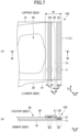
- FIG. 7 is an enlarged view of a portion of the mask 100 where the auxiliary material 30 is provided.
- FIG. 7 (a) is a partial plan view
- FIG. 7 (b) is a cross-sectional view taken along line III-III of FIG. 7 (a) .
- FIG. 8 illustrates a view after the ear material 20 is opened outward in the horizontal direction D2 from the state illustrated in FIG. 7 .
- FIG. 8 (a) is a partial plan view
- FIG. 8 (b) is a cross-sectional view taken along line IV-IV of FIG. 8 (a) .
- the body 10, the ear material 20, and the auxiliary material 30 are stacked in this order.
- the pleated structure 15 ( FIG. 1 and the like) of the mask body 10 is not illustrated.
- the auxiliary materials 30 are interposed between the body 10 and the ear materials 20 so that the body 10 and the ear materials 20 are directly coupled. Specifically, the body 10 and the auxiliary material 30 are coupled at a first coupling portion B1, and the ear material 20 and the auxiliary material 30 are coupled at a second coupling portion B2, so that the body 10 and the ear material 20 are not directly joined.
- the first coupling portion B1 and the second coupling portion B2 can be formed by means of coupling the opposing surfaces of the members by applying pressure and/or heat, such as heat sealing, ultrasonic sealing, non-heating embossing, and the like. Among them, it is preferable to use heat sealing because reliable bonding is possible.
- the body 10 has a function of blocking the entry of foreign matter and preventing droplets generated by the wearer from being scattered, while the ear materials 20 have a function of holding the body 10 by being hung on the ears of the wearer when the wearer wears the ear materials 20. Therefore, the body 10 and the ear materials 20 are usually made of different materials, and the ear materials 20 are preferably made of a material having relatively high stretchability. Therefore, in the conventional structure in which the body 10 and the ear materials 20 are directly coupled, when a force is applied to the mask 100 by pulling the ear materials 20 and the like, the body 10 cannot follow the stretch of the ear materials 20, and the coupling cannot be maintained, and there is a possibility that both are detached from each other.
- the first coupling portion B1 which is the coupling portion between the body 10 and the auxiliary material 30, and the second coupling portion B2, which is the coupling portion between the ear material 20 and the auxiliary material 30, can be formed separately.
- the coupling portion includes the first coupling portion B1 and the second coupling portion B2, and therefore, the force relating to the coupling portion is dispersed, and the ear materials 20 are not likely to be detached.
- the respective coupling portions can be formed in a form suitable for the characteristics of the two members to be directly coupled.
- a material capable of optimizing both of the coupling to the body 10 and the coupling to the ear material 20 can also be selected.
- the indirect coupling between the body 10 and the ear materials 20 is less likely to be broken, and as a result, the mask that is less likely to break even when a force is applied can be obtained.
- the ear materials 20, 20 are separated from each other and opened sideways by pinching and pulling the tab portions 25, 25 provided on the ear materials 20, 20, respectively, constituting the pair.
- the mask 100 might be damaged depending on the configuration of the coupling portion 28 of the ear materials 20, 20 constituting the pair, the way the user separates the ear materials 20, 20, and the like. For example, if it were difficult to start separating the ear materials 20, 20 at the coupling portion 28, the user might pull and open the ear materials 20, 20 by excessive force, and a large force would be applied to the connecting portions between the ear materials 20 and the body 10, which might cause the ear materials 20 to be detached.
- the ear materials 20, 20 are less likely to be detached from the body 10, and a process of putting on the mask 100 can be started in a good condition.
- the auxiliary materials 30 may be made of a non-stretchable material or a material with a low stretchability, and is preferably made of a material having certain stretchability.
- the auxiliary materials 30 may be made of a material of which the shape can be irreversibly changed when a force is applied.
- the auxiliary materials 30 may include a stretchable nonwoven fabric of the same type as the ear materials 20 explained above, but the stretchability of the auxiliary material 30 is preferably smaller than that of the ear material 20 at least in the horizontal direction D2.
- the stretchability of the auxiliary material 30 is preferably greater than that of the body 10 at least in the horizontal direction D2.
- the auxiliary materials 30 having stretchability When the auxiliary materials 30 having stretchability are provided, the difference between the stretch of the body 10 and the stretch of the auxiliary materials 30, and the difference between the stretch of the ear materials 20 and the stretch of the auxiliary materials 30 can be reduced even when the ear materials 20 are pulled.
- the auxiliary materials 30 can serve as a buffer between the body 10 and the ear materials 20. Therefore, the first coupling portion B1 between the body 10 and the auxiliary material 30 and the second coupling portion B2 between the ear material 20 and the auxiliary material 30 are less likely to break, and as a result, the indirect coupling between the body 10 and the ear materials 20 is less likely to break.
- the basis weight of the auxiliary material 30 may be 5 to 100 g/m 2 .
- the thickness of the auxiliary material 30 may be 100 to 1,000 ⁇ m.
- the auxiliary material 30 may be a sheet-shaped member extending along the vertical direction D1 of the mask 100.
- the length of the auxiliary material 30 in the vertical direction D1 is preferably the same as the length of the mask 100 in the vertical direction D1 (the length of the body 10 in the vertical direction D1), but may be shorter than the length of the mask 100 in the vertical direction D1.
- an outer end 31 of the auxiliary material 30 in the horizontal direction D2 may be, in the horizontal direction D2, inside or outside an outer end 11 of the body 10 in the horizontal direction D2, but is preferably aligned with the outer end 11 of the body 10 in the horizontal direction D2 as illustrated in FIG. 7 (a) .
- the length (width) W of the auxiliary material 30 in the horizontal direction D2 is preferably 15 to 35 mm, depending on the size and configuration of the entire mask 100 and the sizes, shapes, and materials of the body 10 and the ear materials 20.
- the length in the horizontal direction D2 is within the above range, the areas of the first coupling portion B1 and the second coupling portion B2 can be sufficiently secured, while the auxiliary materials 30 do not interfere with the separation/expansion operation and/or the process of putting on the mask 100 at the start of use, and do not interfere with the functions of the body 10 and the ear materials 20.
- the width W of the auxiliary material 30 may be such that the auxiliary material 30 overlaps the opening 29 of the ear material 20. However, the width W of the auxiliary material 30 may be set so that the auxiliary material 30 does not overlap the opening 29 of the ear material 20.
- the auxiliary materials 30 are disposed on the outer surface side of the body 10. Therefore, even when the mask 100 is worn, the auxiliary materials 30 are unlikely to come into contact with the face of the wearer, and a good fit achieved by the mask 100 according to the present embodiment is not hindered.
- the ear material 20 may function to press both sides of the body 10 toward the face of the wearer, while the auxiliary material 30 stacked on the outer surface side of the body 10 may also function to press, integrally with the ear material 20, the body 10 toward the face at least partially.
- the gap between the face and both sides of the body 10 can be further reduced, and the function of the mask 100 can be improved.
- the first coupling portion B1 which is the coupling portion between the body 10 and the auxiliary material 30, is situated outside the second coupling portion B2, which is the coupling portion between the ear material 20 and the auxiliary material 30, in the horizontal direction D2.
- auxiliary material 30 (outside in the horizontal direction D2) remains fixed to the body 10 due to the presence of the first coupling portion B1, but the inner side of the auxiliary material in the horizontal direction D2 is opened outward (sideways) in the horizontal direction D2 together with the ear material 20 by the second coupling portion B2 ( FIGs. 8 (a) and (b) ).
- the auxiliary material 30 is bent in the horizontal direction D2 by a line along the vertical direction D1.
- the bent auxiliary material 30 generates a restoring force (a force for returning from a folded state to a state before being folded) according to the characteristics of the material constituting the auxiliary material 30.
- a restoring force a force for returning from a folded state to a state before being folded
- the ear materials 20 and at least portions of the auxiliary materials 30 press both sides of the body 10 toward the face, but such pressing at both sides of the body 10 may be improved by bending the auxiliary materials 30. As illustrated in FIGs.
- the auxiliary material 30 is disposed on the outer surface side of the ear material 20 and on the outermost surface of the mask 100
- the auxiliary material 30 is disposed on the inner side of the ear material 20 (face side) when the ear material 20 is opened outwardly in the horizontal direction D2, so that the function of pressing both sides of the body 10 toward the face is further enhanced. Therefore, the effect of reducing the gap between the mask body and the face is further improved.
- the auxiliary materials 30 In a configuration in which the auxiliary materials 30 are bent when the ear materials 20 are expanded, the auxiliary materials 30 preferably have a relatively high bending springback (strength of springback force when bent), and for example, may have a bending springback larger than that of the ear materials 20. Thereby, the restoring force of the auxiliary materials 30 that are bent is enhanced, and the action of the auxiliary materials 30 for pushing the body 10 toward the inside (face side) can be further improved.
- a relatively high bending springback stress of springback force when bent
- an outer end 21 of the ear material 20 in the horizontal direction D2 is located on the inner side in the horizontal direction D2 with respect to an outer end 11 of the body 10 in the horizontal direction D2.
- the ear materials 20 are shifted toward the inner side in the horizontal direction D2 with respect to the body 10. Therefore, when the body 10, the ear material 20, and the auxiliary material 30 are laminated in order, a portion where the auxiliary material 30 can directly come into contact with the body 10 and a portion where the auxiliary material 30 can directly come into contact with the ear material 20 can be easily formed without performing a process such as folding back.
- the first coupling portion B1 between the body 10 and the auxiliary material 30, and the second coupling portion B2 between the ear material 20 and the auxiliary material 30 can be formed without complicated structure and process.
- the auxiliary material 30 is provided on the ear material 20 such that the outer end 21 of the ear material 20 in the horizontal direction D2 is situated on the inner side in the horizontal direction D2 with respect to the outer end 31 of the auxiliary material 30 in the horizontal direction D2, and a combined body obtained by coupling the ear material 20 and the auxiliary material 30 at the second coupling portion B2 is prepared.
- the combined body is provided on the body 10 in such a manner that the outer end 21 of the ear material 20 in the horizontal direction D2 is situated on the inner side in the horizontal direction D2 with respect to the outer end 11 of the body 10 in the horizontal direction D2.
- a portion where the outer end 11 of the body 10 in the horizontal direction D2 and the auxiliary material 30 are in direct contact with each other can be obtained, so that the first coupling portion B1 can be formed in a state where the combined body and the body 10 are superposed.
- the first coupling portion B1 is preferably formed over the vertical direction D1.
- a length (width) w 1 ( FIG. 7 (a) ) of the first coupling portion B1 in the horizontal direction D2 may be 3 to 10 mm.
- the width w 1 of the first coupling portion B1 is constant in the vertical direction D1, but the width w 1 does not necessarily have to be constant and may vary depending on the location.
- the width w 1 is within the above range, a reliable coupling can be formed between the body 10 and the auxiliary material 30, and the flexibility of the entirety of the mask 100 can be prevented from being damaged by the hardening of the first coupling portion B1. Furthermore, discomfort or the like which occurs when the first coupling portion B1 comes into contact with the face can be reduced.
- the second coupling portion B2 is also preferably formed over the vertical direction D1.
- a length (width) w 2 ( FIG. 7 (a) ) of the second coupling portion B2 in the horizontal direction D2 may be 3 to 10 mm.
- the width w 2 of the first coupling portion B1 is constant in the vertical direction D1, but the width w 2 does not necessarily have to be constant and may vary depending on the location.
- a reliable coupling can be formed between the ear material 20 and the auxiliary material 30, and the flexibility of the entirety of the mask 100 can be prevented from being damaged by the hardening of the second connection portion B2.
- the first coupling portion B1 and the second coupling portion B2 are preferably spaced apart from each other.
- a distance w 0 between the first coupling portion B1 and the second coupling portion B2 may be 3 to 13 mm.
- the distance w 0 is preferably larger than the width w 1 of the first coupling portion B1.
- the ear material 20 and the auxiliary material 30 are moved such that the ear material 20 is turned over and the auxiliary material 30 is bent about a position in proximity to the inner end of the first coupling portion B1 in the horizontal direction D2. Therefore, it is preferable that a distance s between the inner end of the first coupling portion B1 in the horizontal direction D2 and the outer end 21 of the ear material 20 in the horizontal direction D2 is secured to some extent. Furthermore, when the distance s is not excessively increased, the length of the ear material 20 in the horizontal direction D2 can be prevented from being shortened.
- the distance s may be 1 to 10 mm.
- the welded portion formed by the heat sealing may be continuous or discontinuous in the vertical direction D1 and/or the horizontal direction D2. In the case of being discontinuous, multiple welded portions may be provided over the entire coupling portion. When the welded portions are discontinuously provided, a reliable coupling can be formed while securing a certain degree of flexibility in the coupling portion.
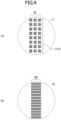
- FIG. 9 (a) and (b) illustrate enlarged views of portions V and VI, respectively, of FIG. 7 (a) .
- the first coupling portion B1 includes multiple welded portions discontinuous in both the vertical direction D1 and the horizontal direction D2. Specifically, the welded portions in square shapes are disposed vertically and horizontally with predetermined intervals from each other. When discontinuous welded portions are provided in the vertical direction D1 and the horizontal direction D2 of the coupling portion, the coupling portion having high flexibility is obtained over the entirety of the first coupling portion B1 while the reliable coupling is formed.
- the second coupling portion B2 includes multiple welded portions discontinuous in the vertical direction D1.
- the welded portion included in the second coupling B2 has a bar shape (or line shape) extending in the horizontal direction D2, more specifically, has a rectangular shape. Since the ear material 20 is pulled while being worn, the second coupling portion B2 (the ear material 20 and the auxiliary material 30 coupled by the second coupling portion B2) is particularly susceptible to the force in the horizontal direction D2. Therefore, the welded portion included in the second coupling portion B2 is formed in a bar shape continuous in the horizontal direction D2, so that when the ear material 20 is pulled in the horizontal direction D2, the ear material 20 can be suitably prevented from being detached.
- the shape of the welded portion of the coupling portion is not limited to that illustrated in the drawings, provided that the coupling portion capable of sufficiently maintaining strength can be formed.
- the welded portion may be formed in a shape having a width narrower than the length, i.e., in a linear shape (linear or curved shape), or in a dot shape (shape visible as a dot).
- the shape of each welded portion in a plan view may be any shape, such as: a quadrilateral such as a rectangle and a diamond; a polygon other than a quadrilateral; a circle; an ellipse; and the like.
- the auxiliary material 30 interposed for coupling of the body 10 and the ear material 20 is provided as a single layer on the outermost side of the mask 100, but the arrangement of the auxiliary material 30 is not limited to the example illustrated in the drawing. Furthermore, the auxiliary material 30 may be folded in a state prior to the start of use and composed of 2 layers.
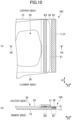
- FIG. 10 illustrates a modified embodiment of the mask 100 according to the present embodiment.
- FIG. 10 is a view corresponding to FIG. 7 , and illustrates an enlarged view of a portion of the mask 100 where the auxiliary material 30 is provided.
- FIG. 10 (a) is a partial plan view
- FIG. 10 (b) illustrates a cross-sectional view taken along line VII-VII of FIG. 10 (a) .
- FIG. 11 illustrates a view after the ear materials 20 are opened outward in the horizontal direction D2 from the state illustrated in FIG. 10 .
- FIG. 11 (a) is a partial plan view
- FIG. 11 (b) is a cross-sectional view taken along line VIII-VIII of FIG. 11 (a) .
- the auxiliary material 30 is disposed on the outside of the ear material 20.
- the basic configuration other than the above is the same as the basic configuration described with reference to FIGs. 7 and 8 , and substantially the same actions and effects can be obtained.
- a mask body ear materials, constituting a pair, coupled to the mask body; and auxiliary materials provided on an outer surface side of the mask body, wherein in a state before start of use, the ear materials, constituting the pair, are separably coupled with each other, and provided on the outer surface side of the mask body, outlines of the ear materials have a wavy shape, and the ear materials, constituting the pair, are coupled to an outer surface in side portions of the mask body via the auxiliary materials.
- the ear materials, constituting the pair are coupled to the mask body via the auxiliary materials, and therefore, the mask can be structured without directly coupling the ear materials and the mask body. Therefore, the coupling portion between the mask body and the auxiliary material and the coupling portion between the ear material and the auxiliary material can be formed separately. Specifically, the respective coupling portions can be formed separately in a form suitable for the materials of the two members to be directly coupled. Thus, even if the ear materials are pulled when the mask is put on, an indirect bonding that does not readily break can be formed between the ear materials and the mask body without damaging the function of the members and the fit, and the robust mask with good fit can be obtained.
- the ear materials, constituting the pair are separably connected to each other, and the ear materials, constituting the pair, can be separated from each other and opened sideways at the start of use.
- the ear materials may be pulled by an excessively large force and the mask might be damaged.
- the ear materials and the mask body are not directly coupled but are coupled via the auxiliary materials as described above, and therefore, the mask that is not easily broken even when separating the pair of ear materials at the start of use can be formed.
- the ear materials are pulled toward the ears of the wearer, and accordingly, a force is applied to the coupling portions of the ear materials with the mask body so that they are pressed against the face of the wearer.
- the ear materials, constituting the pair are coupled to the outer surface side of the mask body, both side portions of the mask body are disposed on the inner side of the ear materials (the face side of the wearer) while being worn. Therefore, both sides of the mask body are pressed against the face by the ear material.
- the gap between the mask body and the face can be reduced at both side portions of the mask body, and the function of the mask, for example, the function of blocking foreign matter, the function of preventing droplets generated by the wearer from being scattered, and the like, can be improved.
- the ear materials are not provided on the inner side of both side portions (face side) of the mask body, the ear materials do not come into contact with the face of the wearer at both side portions of the mask body when the mask is worn, so that a better fit can be obtained.
- the mask includes a vertical direction corresponding to a height direction of a face of a wearer and a horizontal direction orthogonal to the vertical direction, and a stretchability of the auxiliary materials at least in a horizontal direction is higher than a stretchability of the mask body in the horizontal direction, and is lower than a stretchability of the ear material in the horizontal direction.
- the ear materials are members to be hung on the ears of the wearer while being worn, and are often composed of a material having a higher stretchability than that of the mask body. Therefore, when the ear materials and the mask body are directly coupled, the mask body does not readily follow deformation of expansion and contraction of the ear materials, and the ear materials and the mask body may be separated depending on the difference between the expansion and contraction of the ear materials and the expansion and contraction of the mask body and/or the extent of the expansion and contraction of the ear materials during use.
- a material having a stretchability, at least in the horizontal direction, that is in between the stretchability of the mask body and the stretchability of the ear materials is used as the material of the auxiliary materials, and therefore, even when the stretchability of the ear materials and the stretchability of the body are greatly different, the auxiliary materials can buffer the difference in the stretchability and reduce the possibility of separating the ear materials and the body.
- the body and the auxiliary materials are coupled by first coupling portions
- the ear materials and the auxiliary materials are coupled by second coupling portions
- the second coupling portions are situated spaced apart from the first coupling portions such that the second coupling portions are on an inner side in a horizontal direction relative to the first coupling portions.
- the first coupling portion which is a coupling portion between the body and the auxiliary material
- the second coupling portion which is a coupling portion between the ear material and the auxiliary material
- the auxiliary materials are bent in the horizontal direction.
- the bent auxiliary materials have a restoring force (a force to return from the folded state to the state before being folded) corresponding to the characteristics of the material constituting the auxiliary materials. Therefore, when the mask is worn, the restoring force of the auxiliary materials is applied from the outer surface side of the mask to the inner surface side (face side), so that the action of reducing the gap between the both side portions of the mask body and the face can be enhanced.
- the auxiliary materials are provided on outer surface sides of the ear materials.
- the auxiliary materials are disposed on the outer surface sides of the ear materials, and therefore, when the ear materials, constituting the pair, are opened when the mask is worn, the ear materials are disposed on the outermost side and the auxiliary materials are disposed on the inner side relative to the ear materials. Therefore, when the ear materials are hung on the ears and pulled, the ear materials function to press the auxiliary materials and the mask body toward the face at the side portions of the mask. This further improves the action of reducing the gap between the mask body and the face at both side portions (in areas at the ends in the horizontal direction) of the mask body.
- an outer end of each of the ear materials in the horizontal direction is situated on an inner side relative to an outer end of the mask body in the horizontal direction.
- the positions of the outer ends of the ear materials in the horizontal direction and the positions of the outer ends of the mask body in the horizontal direction are shifted, and therefore, the mask body and the ear materials are sequentially laminated from the inner surface side of the mask to the outer surface side, and the auxiliary materials are laminated so as to cover both the mask body and the ear materials, so that the auxiliary materials can be brought into surface contact with both the mask body and the ear materials. Therefore, a coupling portion (first coupling portion) between the mask body and the auxiliary materials and a coupling portion (second coupling portion) between the ear materials and the auxiliary materials can be simply and easily formed without bending or folding the auxiliary materials and/or the ear materials.
- each of the ear materials, constituting the pair is provided with a tab portion protruding from an edge of the mask body in a plan view, and at the start of use, the ear materials, constituting the pair, are separated from each other by pinching and pulling the tab portion.
- the user holds and pulls the tab portions with both hands, separates the ear materials which are coupled to each other, and further opens the ear materials to both sides.
- the tab portions provided on the ear materials, constituting the pair are formed so as to protrude from the edge of the mask body, so that user's fingers are less likely to touch the mask body when the user holds the tab portions. Therefore, the user can separate and open sideways the ear materials, constituting the pair, while maintaining the hygienic condition of the mask.
Landscapes
- Health & Medical Sciences (AREA)
- General Health & Medical Sciences (AREA)
- Physical Education & Sports Medicine (AREA)
- Engineering & Computer Science (AREA)
- Textile Engineering (AREA)
- Respiratory Apparatuses And Protective Means (AREA)
Abstract
Description
- The present invention relates to a mask.
- A known configuration of a mask to be worn on the face includes: a mask body that at least partially covers the face of a wearer; and ear materials (or ear hooks), constituting a pair, each being coupled to the mask body, i.e., a pair of members that can be hung on the ears of the wearer in order to hold the mask body at a predetermined position.
- In recent years, the composition of the mask has been studied in various ways not only from the viewpoint of improving the function of the mask and improving the fit, but also from the viewpoint of ease of handling in manufacturing. For example,
PTL 1 discloses a mask that includes a mask body portion and ear hook portions connected to the mask body portion, wherein the ear hook portions are connected to respective end portion areas, and the ear hook portions connected to the respective end portion areas of the body are configured to be accommodated within the outer shape of the mask body in a plan view of the mask, and the mask includes a connection portion that connects the ear hook portions to each other within the outer shape of the mask body. - PTL 1:
Japanese Patent No. 5762803 - In order to use the mask disclosed in
PTL 1, it is necessary to first separate the coupled ear hook portions from each other and open them sideways. However, depending on the construction of coupling portions of the ear hook portions and the method of separation by the user, the connection portions between the ear hook portions and the mask body might be damaged when the ear hook portions are separated and opened. It is also possible to harden the connection portions in order to form strong bonding, but the flexibility of the mask may be lost, and discomfort may occur when the connection portions come into contact with the skin. - In view of the above, it is an object of one aspect of the present invention to provide a robust mask with good fit.
- According to one aspect of the present invention, included are a mask body; ear materials, constituting a pair, coupled to the mask body; and auxiliary materials provided on an outer surface side of the mask body, wherein in a state before start of use, the ear materials, constituting the pair, are separably coupled with each other, and provided on the outer surface side of the mask body, outlines of the ear materials have a wavy shape, and the ear materials, constituting the pair, are coupled to an outer surface in side portions of the mask body via the auxiliary materials.
- According to one aspect of the present invention, a robust mask with good fit can be provided.
-
-
FIG. 1 is a plan view of a mask according to an embodiment of the present invention as seen from the outside. -
FIG. 2 is a plan view of the mask illustrated inFIG. 1 as seen from the inside (face side). -
FIG. 3 is a view for explaining an example of use of the mask illustrated inFIG. 1 . -
FIG. 4 is a cross-sectional view taken along line I-I ofFIG. 3 . -
FIG. 5 is a plan view of the mask illustrated inFIG. 3 after the ear materials, constituting the pair, is opened sideways. -
FIG. 6 is a cross-sectional view taken along line II-II ofFIG. 5 . -
FIG. 7 is an enlarged plan view and cross-sectional view of a portion where an auxiliary material is provided, in a state before start of use of the mask. -
FIG. 8 is an enlarged plan view and cross-sectional view of a portion where an auxiliary material is provided, in a state after the ear materials are opened sideways. -
FIG. 9 is an enlarged view of a first coupling portion and a second coupling portion. -
FIG. 10 is an enlarged plan view and a cross-sectional view of a portion provided with an auxiliary material in a state before start of use of the mask according to a modified embodiment of the present embodiment. -
FIG. 11 is an enlarged plan view and a cross-sectional view of a portion provided with an auxiliary material after the ear materials of the mask according to the example ofFIG. 10 are opened sideways. - Hereinafter, embodiments of the present invention are described in detail with reference to the drawings. In each of the drawings, unless otherwise explained, the same or corresponding components may be denoted with the same reference numerals and the description thereof may be omitted. The drawings are schematic for helping understanding of the invention.
- A mask according to an embodiment of the present invention may be a mask capable of covering the face of a wearer, more specifically, covering at least the nose and the mouth of a wearer. The mask according to this embodiment can have a function of preventing foreign matter from reaching the face and preventing droplets generated by the wearer from being scattered, and is also referred to as a sanitary mask or surgical mask. The mask may be disposable or reusable by washing.
-
FIG. 1 is a plan view of amask 100 according to the present embodiment.FIG. 1 is a view of themask 100 as seen from the outside, i.e., from the side exposed to the outside and facing away from the face when themask 100 is worn.FIG. 2 is a plan view of the mask as seen from the inside (face side). - As illustrated in
FIG. 1 , themask 100 according to the present embodiment includes: a mask body (which may be simply referred to as a body) 10 which is disposed in front of the face of the wearer when the mask is worn and can mainly cover the nose and mouth of the wearer; andear materials mask body 10. Themask body 10 has a vertical direction D1 corresponding to the height direction of the wearer's face when wearing the mask and a horizontal direction D2 orthogonal to the vertical direction D1. In the form ofFIG. 1 , themask body 10 has a rectangular shape in a plan view having long sides in the horizontal direction D2, but the shape of themask body 10 in a plan view is not limited to the shape as illustrated in the drawings. - As illustrated in
FIGs. 1 and2 , themask body 10 has a pleatedstructure 15 formed by multiple pleats arranged side by side in the vertical direction D1. The pleats of thepleated structure 15 are formed by folding a sheet constituting thebody 10 at fold lines along the horizontal direction D2. In a state in which multiple pleats are formed, the side portions (the ends in the horizontal direction D2) of themask body 10 are joined and fixed. Therefore, when themask 100 is used, the pleats of thepleated structure 15 are extended in the vertical direction D1, so that the center in the horizontal direction D2 is curved so as to protrude toward the outer surface side of themask 100, and can be deformed into a shape adapted to the three-dimensional shape of the face. The specific configuration of thepleated structure 15 is not particularly limited and may be a conventional configuration formed in a mask body. - As illustrated in
FIGs. 1 and2 , theear materials body 10. As illustrated inFIG. 1 , eachear member 20 may be in an annular shape, or may have a shape that includes an annulus in a plan view. When being worn, theear materials 20 can be hung on the ears by allowing the ears of the wearer to enter the inside of the ring of eachear material 20, i.e., an opening 29 at the center of eachear material 20. - As illustrated in
FIG. 1 , the outline of the ring of theear material 20 may have a wavy shape or an uneven shape. The wavy shape may be provided on at least one of the inner outline and the outer outline of the ring, but is preferably provided on at least the inner outline. The wavy shape does not have to be provided on the entire outline of the ring of theear material 20, and it is preferable that, for example, the wavy shape is formed in a portion of the ear material that is in contact with the ear when themask 100 is worn, i.e., a portion of theear material 20 that is situated near the center of themask 100 in the horizontal direction D2 before the start of use. In particular, since the wavy shape is provided on the inner outline of the portion in contact with the ear when themask 100 is worn, the protruding portion included in the wavy shape is easily moved independently, so that theear material 20 is easily fitted to the shape of the ear, and theear material 20 can be stably disposed behind the ear when the mask is worn. - The
ear materials separable coupling portion 28 between theear materials FIG. 1 . Thecoupling portion 28 may also be formed by reducing the thickness of the sheet or by other means to weaken the border between theear materials ear materials coupling portion 28. - The
mask body 10 may have a multilayer structure formed by laminating multiple layers. For example, the structure may include at least three layers sandwiched between an outer layer and an inner layer of an intermediate layer having an enhanced function of collecting foreign matter (dust, pollen, bacteria, viruses, and the like). Each layer constituting thebody 10 may include a fiber-containing layer such as a nonwoven fabric, a woven fabric, a knitted fabric, and the like, and preferably includes a nonwoven fabric. Examples of the nonwoven fabric include a spunbond nonwoven fabric, a spunlace nonwoven fabric, a meltblown nonwoven fabric, an air through nonwoven fabric, a point bond nonwoven fabric, and the like. A meltblown nonwoven fabric which can contain fine fibers is preferably used for the intermediate layer. The fibers constituting the fiber-containing layer are preferably resin fibers, and the resin types of the resin fibers include polyethylene, polypropylene, polyethylene terephthalate, nylon, and the like. The basis weight of the outer and inner layers may be 10 to 50 g/m2, preferably 15 to 50 g/m2. The basis weight of the intermediate layer having a high foreign matter collecting property is preferably 10 to 100 g/m2 and more preferably 15 to 50 g/m2. - The
ear materials 20 may be formed of a material having stretchability, preferably a material having higher stretchability than thebody 10. Theear material 20 may have stretchability at least in the horizontal direction D2, and may have stretchability in both the vertical direction D1 and the horizontal direction D2. The stretchability in the vertical direction D1 and the stretchability in the horizontal direction D2 may be the same or different from each other. When the stretchability in the vertical direction D1 is different from the stretchability in the horizontal direction D2, it is preferable that the stretchability in the horizontal direction D2 is higher than the stretchability in the horizontal direction D2 of thebody 10. When worn, theear materials 20 are hung on the ears of the wearer, and are pulled mainly in the horizontal direction D2. Therefore, by having stretchability at least in the horizontal direction D2, thebody 10 can be better positioned and fixed in the front of the face, and the load of theear materials 20 applied to the ears can be reduced. - The
ear material 20 may include a stretchable fiber-containing sheet and/or may include a stretchable or elastic film. The fiber-containing sheet includes a nonwoven fabric, a woven fabric, a knitted fabric, and the like, and among these, a nonwoven fabric is preferably used because of its good touch and breathability. Examples of nonwoven fabric include an air-through nonwoven fabric, a spunbond nonwoven fabric, a spunlace nonwoven fabric, a needle punch nonwoven fabric, a chemical bond nonwoven fabric, and the like. The fibers contained in the nonwoven fabric are preferably resin fibers, and the resin types of the resin fibers include polyethylene, polypropylene, polyethylene terephthalate, nylon, and the like. - For example, the
ear materials 20 may contain a single layer of the above stretchable fiber-containing sheet or stretchable film, or may be constituted by laminating multiple layers of the above stretchable fiber-containing sheets and/or stretchable films by laminating the fiber-containing sheets and the stretchable films. When the fiber-containing sheet has stretchability, the stretchability may be exhibited by the stretchable fibers contained in the fiber-containing sheet, for example, by the material of the fibers having stretchability or the fibers being crimped fibers. Alternatively, the stretchability may be exhibited by a predetermined physical structure, for example, by having irregularities on the surface. Furthermore, theear materials 20 may be formed by sandwiching a thread-like rubber with a fiber-containing sheet having stretchability or not having stretchability. When the stretchability of the fiber-containing sheet is low or is not provided, the fiber-containing sheets may be attached to both sides while the thread-like rubber is stretched. - Specifically, the
ear materials 20 may be made of a single-layer nonwoven fabric such as a stretchable air-through nonwoven fabric, a stretchable spunbond nonwoven fabric, a stretchable spunlace nonwoven fabric, a stretchable needle punch nonwoven fabric, a stretchable chemical bond nonwoven fabric, or the like. In addition, a material including multiple layers of nonwoven fabric such as spunbond/melt blown/spunbond may be used. Furthermore, a laminated sheet such as a nonwoven fabric/stretchable film or a nonwoven fabric/stretchable film/nonwoven fabric (for example, spunbond/stretchable film/spunbond, air-through/stretchable film/air-through, and the like) can be used. When theear materials 20 are made of multiple layers, the layers may be bonded to each other with a stretchable or non-stretchable hot-melt nonwoven fabric (a nonwoven fabric whose fibers are softened or melted by heating and can be bonded to other members). The basis weight of theear materials 20 may be 20 to 150 g/m2. Theear materials 20 may have a thickness of 100 to 3,000 µm. - The
ear materials body 10. Specifically, theear materials body 10 viaauxiliary materials 30, 30 (the auxiliary materials are explained later in detail). Specifically, the outer portions of theear materials body 10, and the other portions are not coupled to thebody 10. When themask 100 according to the present embodiment starts to be used, before themask 100 is worn, the separable coupling between theear materials ear materials ear materials body 10 are opened sideways in the horizontal direction D2 (also referred to as an expansion operation). Such separation and expansion operations, and the configuration related to such operation are hereinafter explained in detail. -
FIG. 3 illustrates a state in which themask 100 illustrated inFIG. 1 is about to be used.FIG. 4 is a cross-sectional view taken along line I-I ofFIG. 3 . At the start of use, the user can pull theear materials FIG. 3 . As a result, theseparable coupling portion 28 can be first uncoupled. If thecoupling portion 28 includes perforations formed along the border line between theear materials ear materials ear materials FIGs. 3 and4 while holding them. -
FIG. 5 illustrates a state in which theear materials FIG. 3 .FIG. 6 is a cross-sectional view taken along line II-II ofFIG. 5 . As illustrated inFIGs. 5 and6 , when theear materials ear materials body 10 in the state before start of use is exposed. Theear materials body 10, and the entire outer surface of thebody 10 is exposed. - As illustrated in
FIG. 3 , when the user opens, outward in the horizontal direction D2, thetab portions ear materials tab portions mask 100, for example, the outer surface of themask 100 faces the user opening theear materials mask 100 according to the present embodiment is suitable for being worn by another wearer. For example, while themask 100 is placed with the outside of themask 100 facing upward (with the outer surface of thebody 10 facing upward), the user opens theear materials mask 100 is moved to the face of another wearer while theear materials mask body 10 is arranged at a desired position of the wearer's face, and at this occasion, theear materials mask 100 is not changed. Therefore, themask 100 according to the present embodiment can be suitably used when the mask is worn by a person who has difficulty wearing the mask by himself or herself, such as a child or a sick person. - Furthermore, since the
ear materials body 10 as described above, the possibility of the user's hand touching the inside of themask 100 can be reduced or eliminated when theear materials ear materials mask 100 is worn can be performed hygienically. - Furthermore, as illustrated in
FIG. 3 , theear materials tab portions ear materials tab portions body 10 in a plan view. Since thetab portions body 10, the user can pinch thetab portions body 10 itself, i.e., without touching the outer surface or the inner surface of thebody 10. The user can separate and expand theear materials body 10 or without appreciably touching thebody 10. Therefore, even in a situation where the user cannot give sufficient consideration to hand hygiene, themask 100 in a good hygiene condition can be worn by the user or by another person. Furthermore, it is preferable that thetab portions FIG. 3 ) of thebody 10 in a plan view, because the separation and expansion operation of the ear material can be performed naturally. - Since the
ear materials 20 have thetab portions tab portions 25, 2 when or after theear materials 20 are hung on the ears of the wearer. Specifically, the positions of theear materials 20 can be adjusted by shifting the ear materials in the circumferential direction of theear materials 20 relative to the ears with thetab portions ear materials 20 can be adjusted by pulling theear materials 20 toward the rear side and loosening them. - The maximum length in the vertical direction D1 of the portion of the
tab portion 25 protruding from the lower end of thebody 10, i.e., the length in the vertical direction D1 from the lower end of the body to the vertex of the portion of thetab portion 25 protruding, may be 5 to 15 mm. The length in the horizontal direction D2 from the edge of themask 100 or thebody 10 in the horizontal direction D2 to the vertex of the protruding portion, of thetab portion 25 that is closer to the edge, is preferably 45 to 90% with respect to 1/2 of the length in the horizontal direction D2 of the entirety of themask 100 or thebody 10. - While the
mask 100 is worn, i.e., while theear materials ear materials ear materials body 10 are pressed toward the face of the wearer. In the present embodiment, theear materials FIGs. 3 and4 ). Therefore, while themask 100 is worn, portions of theear materials 20 are disposed on the outer sides of both sides of the body 10 (FIGs. 5 and6 ), i.e., both sides of thebody 10 are disposed between theear materials 20 and the face of the wearer, so that both sides of thebody 10 are pressed against the face by theear materials 20. Thereby, the gap between thebody 10 and the face can be reduced at both sides of themask body 10, and the function of the mask, for example, the function of blocking foreign matter, the function of preventing droplets generated by the wearer from being scattered, and the like, can be improved. In addition, theear materials 20 are not arranged on the inner sides of both side portions (face side) of the body, and theear materials 20 do not come into contact with the face of the wearer at both side portions of thebody 10 while being worn, so that a better fit can be obtained. - A
mark 18 that allows the outer and inner surfaces of thebody 10 to be distinguished from each other (distinguishing between front and back) may be formed on the outer surface and/or the inner surface of thebody 10 by embossing, printing, sewing, or the like. The form of themark 18 is not limited as long as it can be visually recognized by the user. As illustrated inFIG. 1 , themark 18 may be letters, numbers, a symbol, a figure, a logo, or the like. - In the present embodiment, as described above, the
ear materials body 10 via theauxiliary materials auxiliary materials -
FIG. 7 is an enlarged view of a portion of themask 100 where theauxiliary material 30 is provided.FIG. 7 (a) is a partial plan view, andFIG. 7 (b) is a cross-sectional view taken along line III-III ofFIG. 7 (a) .FIG. 8 illustrates a view after theear material 20 is opened outward in the horizontal direction D2 from the state illustrated inFIG. 7 .FIG. 8 (a) is a partial plan view, andFIG. 8 (b) is a cross-sectional view taken along line IV-IV ofFIG. 8 (a) . In the examples ofFIGs. 7 and8 , thebody 10, theear material 20, and theauxiliary material 30 are stacked in this order. InFIGs. 7 and8 , the pleated structure 15 (FIG. 1 and the like) of themask body 10 is not illustrated. - The
auxiliary materials 30 are interposed between thebody 10 and theear materials 20 so that thebody 10 and theear materials 20 are directly coupled. Specifically, thebody 10 and theauxiliary material 30 are coupled at a first coupling portion B1, and theear material 20 and theauxiliary material 30 are coupled at a second coupling portion B2, so that thebody 10 and theear material 20 are not directly joined. For example, the first coupling portion B1 and the second coupling portion B2 can be formed by means of coupling the opposing surfaces of the members by applying pressure and/or heat, such as heat sealing, ultrasonic sealing, non-heating embossing, and the like. Among them, it is preferable to use heat sealing because reliable bonding is possible. - As described above, the
body 10 has a function of blocking the entry of foreign matter and preventing droplets generated by the wearer from being scattered, while theear materials 20 have a function of holding thebody 10 by being hung on the ears of the wearer when the wearer wears theear materials 20. Therefore, thebody 10 and theear materials 20 are usually made of different materials, and theear materials 20 are preferably made of a material having relatively high stretchability. Therefore, in the conventional structure in which thebody 10 and theear materials 20 are directly coupled, when a force is applied to themask 100 by pulling theear materials 20 and the like, thebody 10 cannot follow the stretch of theear materials 20, and the coupling cannot be maintained, and there is a possibility that both are detached from each other. - In contrast, according the present embodiment, the first coupling portion B1, which is the coupling portion between the
body 10 and theauxiliary material 30, and the second coupling portion B2, which is the coupling portion between theear material 20 and theauxiliary material 30, can be formed separately. Specifically, the coupling portion includes the first coupling portion B1 and the second coupling portion B2, and therefore, the force relating to the coupling portion is dispersed, and theear materials 20 are not likely to be detached. Furthermore, the respective coupling portions can be formed in a form suitable for the characteristics of the two members to be directly coupled. Furthermore, as the material of theauxiliary material 30, a material capable of optimizing both of the coupling to thebody 10 and the coupling to theear material 20 can also be selected. Thus, the indirect coupling between thebody 10 and theear materials 20 is less likely to be broken, and as a result, the mask that is less likely to break even when a force is applied can be obtained. - As described above, before the
mask 100 according to the present embodiment is worn, theear materials tab portions ear materials ear materials mask 100 might be damaged depending on the configuration of thecoupling portion 28 of theear materials ear materials ear materials coupling portion 28, the user might pull and open theear materials ear materials 20 and thebody 10, which might cause theear materials 20 to be detached. However, according to the present embodiment, even in the separation and expansion operation of theear materials ear materials body 10, and a process of putting on themask 100 can be started in a good condition. - Furthermore, according to the present embodiment, it is not necessary to use a large amount of adhesive agent for firmly bonding the
body 10 and theear materials 20 or to use an adhesive agent that becomes excessively hard after curing, and therefore, the function of each member is not hindered, the flexibility of the mask can be maintained, and the mask with good fit and usability can be obtained. - The
auxiliary materials 30 may be made of a non-stretchable material or a material with a low stretchability, and is preferably made of a material having certain stretchability. Theauxiliary materials 30 may be made of a material of which the shape can be irreversibly changed when a force is applied. Theauxiliary materials 30 may include a stretchable nonwoven fabric of the same type as theear materials 20 explained above, but the stretchability of theauxiliary material 30 is preferably smaller than that of theear material 20 at least in the horizontal direction D2. The stretchability of theauxiliary material 30 is preferably greater than that of thebody 10 at least in the horizontal direction D2. - When the
auxiliary materials 30 having stretchability are provided, the difference between the stretch of thebody 10 and the stretch of theauxiliary materials 30, and the difference between the stretch of theear materials 20 and the stretch of theauxiliary materials 30 can be reduced even when theear materials 20 are pulled. Theauxiliary materials 30 can serve as a buffer between thebody 10 and theear materials 20. Therefore, the first coupling portion B1 between thebody 10 and theauxiliary material 30 and the second coupling portion B2 between theear material 20 and theauxiliary material 30 are less likely to break, and as a result, the indirect coupling between thebody 10 and theear materials 20 is less likely to break. The basis weight of theauxiliary material 30 may be 5 to 100 g/m2. The thickness of theauxiliary material 30 may be 100 to 1,000 µm. - As illustrated in
FIG. 7 (a) , theauxiliary material 30 may be a sheet-shaped member extending along the vertical direction D1 of themask 100. The length of theauxiliary material 30 in the vertical direction D1 is preferably the same as the length of themask 100 in the vertical direction D1 (the length of thebody 10 in the vertical direction D1), but may be shorter than the length of themask 100 in the vertical direction D1. Furthermore, on one side (on either the right or left side) of themask 100 in the horizontal direction D2, anouter end 31 of theauxiliary material 30 in the horizontal direction D2 may be, in the horizontal direction D2, inside or outside anouter end 11 of thebody 10 in the horizontal direction D2, but is preferably aligned with theouter end 11 of thebody 10 in the horizontal direction D2 as illustrated inFIG. 7 (a) . - The length (width) W of the
auxiliary material 30 in the horizontal direction D2 is preferably 15 to 35 mm, depending on the size and configuration of theentire mask 100 and the sizes, shapes, and materials of thebody 10 and theear materials 20. When the length in the horizontal direction D2 is within the above range, the areas of the first coupling portion B1 and the second coupling portion B2 can be sufficiently secured, while theauxiliary materials 30 do not interfere with the separation/expansion operation and/or the process of putting on themask 100 at the start of use, and do not interfere with the functions of thebody 10 and theear materials 20. - As illustrated in
FIG. 7 , the width W of theauxiliary material 30 may be such that theauxiliary material 30 overlaps theopening 29 of theear material 20. However, the width W of theauxiliary material 30 may be set so that theauxiliary material 30 does not overlap theopening 29 of theear material 20. - As illustrated in
FIGs. 7 (a) and 7 (b) , theauxiliary materials 30 are disposed on the outer surface side of thebody 10. Therefore, even when themask 100 is worn, theauxiliary materials 30 are unlikely to come into contact with the face of the wearer, and a good fit achieved by themask 100 according to the present embodiment is not hindered. - Furthermore, as described above, the
ear material 20 according to the present embodiment may function to press both sides of thebody 10 toward the face of the wearer, while theauxiliary material 30 stacked on the outer surface side of thebody 10 may also function to press, integrally with theear material 20, thebody 10 toward the face at least partially. Thus, the gap between the face and both sides of thebody 10 can be further reduced, and the function of themask 100 can be improved. - As illustrated in
FIGs. 7 (a) and 7 (b) , in the state prior to the start of use of themask 100, the first coupling portion B1, which is the coupling portion between thebody 10 and theauxiliary material 30, is situated outside the second coupling portion B2, which is the coupling portion between theear material 20 and theauxiliary material 30, in the horizontal direction D2. Therefore, when theear materials 20 are opened outward in the horizontal direction D2 at the start of use, a portion of the auxiliary material 30 (outside in the horizontal direction D2) remains fixed to thebody 10 due to the presence of the first coupling portion B1, but the inner side of the auxiliary material in the horizontal direction D2 is opened outward (sideways) in the horizontal direction D2 together with theear material 20 by the second coupling portion B2 (FIGs. 8 (a) and (b) ). Specifically, theauxiliary material 30 is bent in the horizontal direction D2 by a line along the vertical direction D1. - The bent
auxiliary material 30 generates a restoring force (a force for returning from a folded state to a state before being folded) according to the characteristics of the material constituting theauxiliary material 30. As described above, while themask 100 is worn, theear materials 20 and at least portions of theauxiliary materials 30 press both sides of thebody 10 toward the face, but such pressing at both sides of thebody 10 may be improved by bending theauxiliary materials 30. As illustrated inFIGs. 7 and8 , in an example in which theauxiliary material 30 is disposed on the outer surface side of theear material 20 and on the outermost surface of themask 100, theauxiliary material 30 is disposed on the inner side of the ear material 20 (face side) when theear material 20 is opened outwardly in the horizontal direction D2, so that the function of pressing both sides of thebody 10 toward the face is further enhanced. Therefore, the effect of reducing the gap between the mask body and the face is further improved. - In a configuration in which the
auxiliary materials 30 are bent when theear materials 20 are expanded, theauxiliary materials 30 preferably have a relatively high bending springback (strength of springback force when bent), and for example, may have a bending springback larger than that of theear materials 20. Thereby, the restoring force of theauxiliary materials 30 that are bent is enhanced, and the action of theauxiliary materials 30 for pushing thebody 10 toward the inside (face side) can be further improved. - In the state before start of use (
FIGs. 7 (a) and 7 (b) ), on one side (left or right side) of themask 100 in the horizontal direction D2, anouter end 21 of theear material 20 in the horizontal direction D2 is located on the inner side in the horizontal direction D2 with respect to anouter end 11 of thebody 10 in the horizontal direction D2. Specifically, theear materials 20 are shifted toward the inner side in the horizontal direction D2 with respect to thebody 10. Therefore, when thebody 10, theear material 20, and theauxiliary material 30 are laminated in order, a portion where theauxiliary material 30 can directly come into contact with thebody 10 and a portion where theauxiliary material 30 can directly come into contact with theear material 20 can be easily formed without performing a process such as folding back. Therefore, the first coupling portion B1 between thebody 10 and theauxiliary material 30, and the second coupling portion B2 between theear material 20 and theauxiliary material 30 can be formed without complicated structure and process. For example, theauxiliary material 30 is provided on theear material 20 such that theouter end 21 of theear material 20 in the horizontal direction D2 is situated on the inner side in the horizontal direction D2 with respect to theouter end 31 of theauxiliary material 30 in the horizontal direction D2, and a combined body obtained by coupling theear material 20 and theauxiliary material 30 at the second coupling portion B2 is prepared. The combined body is provided on thebody 10 in such a manner that theouter end 21 of theear material 20 in the horizontal direction D2 is situated on the inner side in the horizontal direction D2 with respect to theouter end 11 of thebody 10 in the horizontal direction D2. As a result, a portion where theouter end 11 of thebody 10 in the horizontal direction D2 and theauxiliary material 30 are in direct contact with each other can be obtained, so that the first coupling portion B1 can be formed in a state where the combined body and thebody 10 are superposed. - The first coupling portion B1 is preferably formed over the vertical direction D1. A length (width) w1 (
FIG. 7 (a) ) of the first coupling portion B1 in the horizontal direction D2 may be 3 to 10 mm. In the example illustrated inFIG. 7 , the width w1 of the first coupling portion B1 is constant in the vertical direction D1, but the width w1 does not necessarily have to be constant and may vary depending on the location. When the width w1 is within the above range, a reliable coupling can be formed between thebody 10 and theauxiliary material 30, and the flexibility of the entirety of themask 100 can be prevented from being damaged by the hardening of the first coupling portion B1. Furthermore, discomfort or the like which occurs when the first coupling portion B1 comes into contact with the face can be reduced. - The second coupling portion B2 is also preferably formed over the vertical direction D1. A length (width) w2 (
FIG. 7 (a) ) of the second coupling portion B2 in the horizontal direction D2 may be 3 to 10 mm. In the example illustrated inFIG. 7 , the width w2 of the first coupling portion B1 is constant in the vertical direction D1, but the width w2 does not necessarily have to be constant and may vary depending on the location. When the width w2 is within the above range, a reliable coupling can be formed between theear material 20 and theauxiliary material 30, and the flexibility of the entirety of themask 100 can be prevented from being damaged by the hardening of the second connection portion B2. - The first coupling portion B1 and the second coupling portion B2 are preferably spaced apart from each other. A distance w0 between the first coupling portion B1 and the second coupling portion B2 (
FIG. 7 (a) ) may be 3 to 13 mm. The distance w0 is preferably larger than the width w1 of the first coupling portion B1. With the distance w0 being the above value, when theear material 20 is expanded, the turning over of theear material 20 and the bending of theauxiliary material 30 are facilitated, and the flexibility of both side portions of themask 100 can be prevented from being impaired. - When the
ear material 20 is expanded, theear material 20 and theauxiliary material 30 are moved such that theear material 20 is turned over and theauxiliary material 30 is bent about a position in proximity to the inner end of the first coupling portion B1 in the horizontal direction D2. Therefore, it is preferable that a distance s between the inner end of the first coupling portion B1 in the horizontal direction D2 and theouter end 21 of theear material 20 in the horizontal direction D2 is secured to some extent. Furthermore, when the distance s is not excessively increased, the length of theear material 20 in the horizontal direction D2 can be prevented from being shortened. The distance s may be 1 to 10 mm. - When the first coupling portion B1 and the second coupling portion B2 are formed by heat sealing, the welded portion formed by the heat sealing may be continuous or discontinuous in the vertical direction D1 and/or the horizontal direction D2. In the case of being discontinuous, multiple welded portions may be provided over the entire coupling portion. When the welded portions are discontinuously provided, a reliable coupling can be formed while securing a certain degree of flexibility in the coupling portion.
-
FIG. 9 (a) and (b) illustrate enlarged views of portions V and VI, respectively, ofFIG. 7 (a) . As illustrated inFIG. 9 (a) , the first coupling portion B1 includes multiple welded portions discontinuous in both the vertical direction D1 and the horizontal direction D2. Specifically, the welded portions in square shapes are disposed vertically and horizontally with predetermined intervals from each other. When discontinuous welded portions are provided in the vertical direction D1 and the horizontal direction D2 of the coupling portion, the coupling portion having high flexibility is obtained over the entirety of the first coupling portion B1 while the reliable coupling is formed. - Furthermore, as illustrated in
FIG. 9 (b) , the second coupling portion B2 includes multiple welded portions discontinuous in the vertical direction D1. In the illustrated example, the welded portion included in the second coupling B2 has a bar shape (or line shape) extending in the horizontal direction D2, more specifically, has a rectangular shape. Since theear material 20 is pulled while being worn, the second coupling portion B2 (theear material 20 and theauxiliary material 30 coupled by the second coupling portion B2) is particularly susceptible to the force in the horizontal direction D2. Therefore, the welded portion included in the second coupling portion B2 is formed in a bar shape continuous in the horizontal direction D2, so that when theear material 20 is pulled in the horizontal direction D2, theear material 20 can be suitably prevented from being detached. Note that the shape of the welded portion of the coupling portion is not limited to that illustrated in the drawings, provided that the coupling portion capable of sufficiently maintaining strength can be formed. The welded portion may be formed in a shape having a width narrower than the length, i.e., in a linear shape (linear or curved shape), or in a dot shape (shape visible as a dot). Specifically, the shape of each welded portion in a plan view may be any shape, such as: a quadrilateral such as a rectangle and a diamond; a polygon other than a quadrilateral; a circle; an ellipse; and the like. - In the example described above, the
auxiliary material 30 interposed for coupling of thebody 10 and theear material 20 is provided as a single layer on the outermost side of themask 100, but the arrangement of theauxiliary material 30 is not limited to the example illustrated in the drawing. Furthermore, theauxiliary material 30 may be folded in a state prior to the start of use and composed of 2 layers. -
FIG. 10 illustrates a modified embodiment of themask 100 according to the present embodiment.FIG. 10 is a view corresponding toFIG. 7 , and illustrates an enlarged view of a portion of themask 100 where theauxiliary material 30 is provided.FIG. 10 (a) is a partial plan view, andFIG. 10 (b) illustrates a cross-sectional view taken along line VII-VII ofFIG. 10 (a) .FIG. 11 illustrates a view after theear materials 20 are opened outward in the horizontal direction D2 from the state illustrated inFIG. 10 .FIG. 11 (a) is a partial plan view, andFIG. 11 (b) is a cross-sectional view taken along line VIII-VIII ofFIG. 11 (a) . In the modified embodiment illustrated inFIGs. 10 and11 , theauxiliary material 30 is disposed on the outside of theear material 20. The basic configuration other than the above is the same as the basic configuration described with reference toFIGs. 7 and8 , and substantially the same actions and effects can be obtained. - In the example illustrated in
FIGs. 10 (a) and (b) , when both side portions (both end portions in the horizontal direction D2) of themask 100 are viewed from the outside, theear material 20 is disposed on the outermost side, and theauxiliary material 30 is exposed to the outside from theouter end 21 of theear material 20 in the horizontal direction D2. Therefore, when theear material 20 is opened outward and expanded in the horizontal direction D2 at the start of use, the bentauxiliary material 30 is disposed on the outermost side on the side of thebody 10, and theouter end 21 of theear material 20 is covered with theauxiliary material 30. Therefore, theouter end 21 of theear material 20 is not exposed while being worn and can be protected. - Hereinafter, specific aspects of the present invention are supplementarily explained below.
- In an aspect according to
Supplementary Note 1, included are a mask body; ear materials, constituting a pair, coupled to the mask body; and auxiliary materials provided on an outer surface side of the mask body, wherein in a state before start of use, the ear materials, constituting the pair, are separably coupled with each other, and provided on the outer surface side of the mask body, outlines of the ear materials have a wavy shape, and the ear materials, constituting the pair, are coupled to an outer surface in side portions of the mask body via the auxiliary materials. - According to the above-described aspect according to the
Supplementary Note 1, the ear materials, constituting the pair, are coupled to the mask body via the auxiliary materials, and therefore, the mask can be structured without directly coupling the ear materials and the mask body. Therefore, the coupling portion between the mask body and the auxiliary material and the coupling portion between the ear material and the auxiliary material can be formed separately. Specifically, the respective coupling portions can be formed separately in a form suitable for the materials of the two members to be directly coupled. Thus, even if the ear materials are pulled when the mask is put on, an indirect bonding that does not readily break can be formed between the ear materials and the mask body without damaging the function of the members and the fit, and the robust mask with good fit can be obtained. - In this aspect, the ear materials, constituting the pair, are separably connected to each other, and the ear materials, constituting the pair, can be separated from each other and opened sideways at the start of use. During such a separation and expansion operation, depending on the type of coupling between the ear materials, constituting the pair, and/or the manner in which the user separates the ear materials, constituting the pair, from each other, the ear materials may be pulled by an excessively large force and the mask might be damaged. However, in the present embodiment, the ear materials and the mask body are not directly coupled but are coupled via the auxiliary materials as described above, and therefore, the mask that is not easily broken even when separating the pair of ear materials at the start of use can be formed.
- Furthermore, while the mask is worn, i.e., when the ear materials are hung on the ears with the ear materials opened sideways, the ear materials are pulled toward the ears of the wearer, and accordingly, a force is applied to the coupling portions of the ear materials with the mask body so that they are pressed against the face of the wearer. In the present embodiment, since the ear materials, constituting the pair, are coupled to the outer surface side of the mask body, both side portions of the mask body are disposed on the inner side of the ear materials (the face side of the wearer) while being worn. Therefore, both sides of the mask body are pressed against the face by the ear material. Thereby, the gap between the mask body and the face can be reduced at both side portions of the mask body, and the function of the mask, for example, the function of blocking foreign matter, the function of preventing droplets generated by the wearer from being scattered, and the like, can be improved. In addition, since the ear materials are not provided on the inner side of both side portions (face side) of the mask body, the ear materials do not come into contact with the face of the wearer at both side portions of the mask body when the mask is worn, so that a better fit can be obtained.
- In an aspect according to the Supplementary Note 2, the mask includes a vertical direction corresponding to a height direction of a face of a wearer and a horizontal direction orthogonal to the vertical direction, and a stretchability of the auxiliary materials at least in a horizontal direction is higher than a stretchability of the mask body in the horizontal direction, and is lower than a stretchability of the ear material in the horizontal direction.
- The ear materials are members to be hung on the ears of the wearer while being worn, and are often composed of a material having a higher stretchability than that of the mask body. Therefore, when the ear materials and the mask body are directly coupled, the mask body does not readily follow deformation of expansion and contraction of the ear materials, and the ear materials and the mask body may be separated depending on the difference between the expansion and contraction of the ear materials and the expansion and contraction of the mask body and/or the extent of the expansion and contraction of the ear materials during use. In contrast, according to the aspect of the above-described Supplementary Note 2, a material having a stretchability, at least in the horizontal direction, that is in between the stretchability of the mask body and the stretchability of the ear materials is used as the material of the auxiliary materials, and therefore, even when the stretchability of the ear materials and the stretchability of the body are greatly different, the auxiliary materials can buffer the difference in the stretchability and reduce the possibility of separating the ear materials and the body.
- In an aspect according to the Supplementary Note 3, the body and the auxiliary materials are coupled by first coupling portions, the ear materials and the auxiliary materials are coupled by second coupling portions, and in the state before start of use, the second coupling portions are situated spaced apart from the first coupling portions such that the second coupling portions are on an inner side in a horizontal direction relative to the first coupling portions.
- According to the above-described aspect according to the Supplementary Note 4, in the state before start of use, i.e., in a state in which the ear materials, constituting the pair, are not separated and opened, the first coupling portion, which is a coupling portion between the body and the auxiliary material, is formed on the outer side in the horizontal direction, and the second coupling portion, which is a coupling portion between the ear material and the auxiliary material, is formed on the inner side in the horizontal direction relative to the first coupling portion. Therefore, when the ear materials, constituting the pair, are opened sideways (outside in the horizontal direction) at the start of use, while outer portions of the auxiliary materials in the horizontal direction are fixed to the body by the first coupling portion, the inner portions of the auxiliary materials in the horizontal direction are opened together with the ear materials, and therefore, the auxiliary materials are bent in the horizontal direction. The bent auxiliary materials have a restoring force (a force to return from the folded state to the state before being folded) corresponding to the characteristics of the material constituting the auxiliary materials. Therefore, when the mask is worn, the restoring force of the auxiliary materials is applied from the outer surface side of the mask to the inner surface side (face side), so that the action of reducing the gap between the both side portions of the mask body and the face can be enhanced.
- In an aspect according to the Supplementary Note 3, the auxiliary materials are provided on outer surface sides of the ear materials.
- According to the above-described aspect according to the Supplementary Note 4, the auxiliary materials are disposed on the outer surface sides of the ear materials, and therefore, when the ear materials, constituting the pair, are opened when the mask is worn, the ear materials are disposed on the outermost side and the auxiliary materials are disposed on the inner side relative to the ear materials. Therefore, when the ear materials are hung on the ears and pulled, the ear materials function to press the auxiliary materials and the mask body toward the face at the side portions of the mask. This further improves the action of reducing the gap between the mask body and the face at both side portions (in areas at the ends in the horizontal direction) of the mask body.
- In an aspect according to the Supplementary Note 5, an outer end of each of the ear materials in the horizontal direction is situated on an inner side relative to an outer end of the mask body in the horizontal direction.
- According to the above-described aspect according to the Supplementary Note 5, the positions of the outer ends of the ear materials in the horizontal direction and the positions of the outer ends of the mask body in the horizontal direction are shifted, and therefore, the mask body and the ear materials are sequentially laminated from the inner surface side of the mask to the outer surface side, and the auxiliary materials are laminated so as to cover both the mask body and the ear materials, so that the auxiliary materials can be brought into surface contact with both the mask body and the ear materials. Therefore, a coupling portion (first coupling portion) between the mask body and the auxiliary materials and a coupling portion (second coupling portion) between the ear materials and the auxiliary materials can be simply and easily formed without bending or folding the auxiliary materials and/or the ear materials.
- In an aspect according to the Supplementary Note 6, each of the ear materials, constituting the pair, is provided with a tab portion protruding from an edge of the mask body in a plan view, and at the start of use, the ear materials, constituting the pair, are separated from each other by pinching and pulling the tab portion.
- At the time of start of use of the mask according to this aspect, the user holds and pulls the tab portions with both hands, separates the ear materials which are coupled to each other, and further opens the ear materials to both sides. According to the aspect of the above-described Supplementary Note 6, the tab portions provided on the ear materials, constituting the pair, are formed so as to protrude from the edge of the mask body, so that user's fingers are less likely to touch the mask body when the user holds the tab portions. Therefore, the user can separate and open sideways the ear materials, constituting the pair, while maintaining the hygienic condition of the mask.
- This application claims the priority to Basic Application No.
2020-094370 filed with the Japan Patent Office on May 29, 2020 -
- 10
- mask body
- 11
- outer end of mask body in horizontal direction
- 15
- pleated structure
- 20
- ear material
- 21
- outer end of ear material in horizontal direction
- 25
- tab portion
- 28
- separable coupling portion
- 29
- opening
- 30
- auxiliary material
- 31
- outer end of auxiliary material in horizontal direction
- 100
- mask
- B1
- first coupling portion
- B2
- second coupling portion
- w1
- width of first coupling portion
- w2
- width of second coupling portion
- w0
- distance between first coupling portion and second coupling portion
- W
- width of auxiliary material
- s
- distance of inner end in horizontal direction of first coupling portion and outer end in horizontal direction of ear material
Claims (6)
- A mask comprising:a mask body;ear materials, constituting a pair, coupled to the mask body; andauxiliary materials provided on an outer surface side of the mask body,wherein in a state before start of use, the ear materials, constituting the pair, are separably coupled with each other, and provided on the outer surface side of the mask body,outlines of the ear materials have a wavy shape, andthe ear materials, constituting the pair, are coupled to an outer surface in side portions of the mask body via the auxiliary materials.
- The mask according to claim 1, wherein the mask includes a vertical direction corresponding to a height direction of a face of a wearer and a horizontal direction orthogonal to the vertical direction, and
a stretchability of the auxiliary materials at least in a horizontal direction is higher than a stretchability of the mask body in the horizontal direction, and is lower than a stretchability of the ear materials in the horizontal direction. - The mask according to claim 1 or 2, wherein the mask body and the auxiliary materials are coupled by first coupling portions,the ear materials and the auxiliary materials are coupled by second coupling portions, andin the state before start of use, the second coupling portions are situated spaced apart from the first coupling portions such that the second coupling portions being on an inner side in a horizontal direction relative to the first coupling portions.
- The mask according to claim 3, wherein the auxiliary materials are provided on outer surface sides of the ear materials.
- The mask according to claim 4, wherein an outer end of each of the ear materials in the horizontal direction is situated on an inner side relative to an outer end of the mask body in the horizontal direction.
- The mask according to any one of claims 1 to 5, wherein each of the ear materials, constituting the pair, is provided with a tab portion protruding from an edge of the mask body in a plan view, and
at the start of use, the ear materials, constituting the pair, are separated from each other by pinching and pulling the tab portion.
Applications Claiming Priority (2)
| Application Number | Priority Date | Filing Date | Title |
|---|---|---|---|
| JP2020094370A JP7296918B2 (en) | 2020-05-29 | 2020-05-29 | mask |
| PCT/JP2021/020113 WO2021241664A1 (en) | 2020-05-29 | 2021-05-27 | Mask |
Publications (3)
| Publication Number | Publication Date |
|---|---|
| EP4159072A1 true EP4159072A1 (en) | 2023-04-05 |
| EP4159072A4 EP4159072A4 (en) | 2023-11-08 |
| EP4159072B1 EP4159072B1 (en) | 2024-11-20 |
Family
ID=78744580
Family Applications (1)
| Application Number | Title | Priority Date | Filing Date |
|---|---|---|---|
| EP21812960.9A Active EP4159072B1 (en) | 2020-05-29 | 2021-05-27 | Mask |
Country Status (5)
| Country | Link |
|---|---|
| EP (1) | EP4159072B1 (en) |
| JP (1) | JP7296918B2 (en) |
| CN (1) | CN115003185B (en) |
| BR (1) | BR112022023218A2 (en) |
| WO (1) | WO2021241664A1 (en) |
Families Citing this family (1)
| Publication number | Priority date | Publication date | Assignee | Title |
|---|---|---|---|---|
| JP2023128038A (en) * | 2022-03-02 | 2023-09-14 | 大王製紙株式会社 | mask |
Family Cites Families (16)
| Publication number | Priority date | Publication date | Assignee | Title |
|---|---|---|---|---|
| JP4471760B2 (en) * | 2004-07-23 | 2010-06-02 | 株式会社 ユニティー | mask |
| JP3126242U (en) * | 2006-08-07 | 2006-10-19 | 株式会社ワン・ライフ | mask |
| JP5068129B2 (en) * | 2007-09-28 | 2012-11-07 | ユニ・チャーム株式会社 | mask |
| CN101537237B (en) * | 2008-03-21 | 2011-12-28 | 康那香企业股份有限公司 | Method for manufacturing mask with elastic non-woven ear loops |
| JP2010194287A (en) * | 2009-02-26 | 2010-09-09 | Toru Fujisawa | Mask having wave form along circumference |
| JP5436262B2 (en) * | 2010-02-19 | 2014-03-05 | ユニ・チャーム株式会社 | mask |
| JP2011194067A (en) * | 2010-03-19 | 2011-10-06 | Three M Innovative Properties Co | Mask with leak preventing section |
| JP5762803B2 (en) * | 2011-04-08 | 2015-08-12 | ユニ・チャーム株式会社 | mask |
| JP5901900B2 (en) * | 2011-06-28 | 2016-04-13 | ユニ・チャーム株式会社 | mask |
| JP5972092B2 (en) * | 2012-08-06 | 2016-08-17 | サンエムパッケージ 株式会社 | mask |
| JP6700097B2 (en) * | 2016-04-28 | 2020-05-27 | ユニ・チャーム株式会社 | mask |
| TWI645883B (en) * | 2017-07-24 | 2019-01-01 | 台灣康匠製造股份有限公司 | Mask with spread wings and its manufacturing process |
| JP6473860B1 (en) * | 2018-07-06 | 2019-02-20 | 里咲 金本 | mask |
| JP6816075B2 (en) * | 2018-09-05 | 2021-01-20 | スズラン株式会社 | Masks and mask manufacturing methods |
| JP2020094370A (en) | 2018-12-12 | 2020-06-18 | 株式会社勝原製作所 | Functional gatepost |
| KR102069375B1 (en) * | 2019-06-20 | 2020-01-22 | (주)피앤티디 | Earring band length adjustable mask |
-
2020
- 2020-05-29 JP JP2020094370A patent/JP7296918B2/en active Active
-
2021
- 2021-05-27 WO PCT/JP2021/020113 patent/WO2021241664A1/en not_active Ceased
- 2021-05-27 CN CN202180010810.3A patent/CN115003185B/en active Active
- 2021-05-27 EP EP21812960.9A patent/EP4159072B1/en active Active
- 2021-05-27 BR BR112022023218A patent/BR112022023218A2/en unknown
Also Published As
| Publication number | Publication date |
|---|---|
| CN115003185B (en) | 2025-08-29 |
| JP2021188178A (en) | 2021-12-13 |
| JP7296918B2 (en) | 2023-06-23 |
| WO2021241664A1 (en) | 2021-12-02 |
| EP4159072A4 (en) | 2023-11-08 |
| CN115003185A (en) | 2022-09-02 |
| BR112022023218A2 (en) | 2022-12-20 |
| EP4159072B1 (en) | 2024-11-20 |
Similar Documents
| Publication | Publication Date | Title |
|---|---|---|
| TWI893279B (en) | Ear hanging member for mask, and mask | |
| EP4159072B1 (en) | Mask | |
| EP4190194A1 (en) | Mask | |
| EP4159286B1 (en) | Mask | |
| CN116583201B (en) | Face mask | |
| JP6968231B1 (en) | mask | |
| EP4316605B1 (en) | Mask and method for manufacturing mask | |
| JP7753604B2 (en) | mask | |
| JP7746662B2 (en) | Mask and mask manufacturing method | |
| JP2024176845A (en) | mask | |
| JP2024146148A (en) | mask | |
| WO2025204013A1 (en) | Mask | |
| JP2022150304A (en) | mask | |
| JP2023128038A (en) | mask |
Legal Events
| Date | Code | Title | Description |
|---|---|---|---|
| STAA | Information on the status of an ep patent application or granted ep patent |
Free format text: STATUS: THE INTERNATIONAL PUBLICATION HAS BEEN MADE |
|
| PUAI | Public reference made under article 153(3) epc to a published international application that has entered the european phase |
Free format text: ORIGINAL CODE: 0009012 |
|
| STAA | Information on the status of an ep patent application or granted ep patent |
Free format text: STATUS: REQUEST FOR EXAMINATION WAS MADE |
|
| 17P | Request for examination filed |
Effective date: 20220823 |
|
| AK | Designated contracting states |
Kind code of ref document: A1 Designated state(s): AL AT BE BG CH CY CZ DE DK EE ES FI FR GB GR HR HU IE IS IT LI LT LU LV MC MK MT NL NO PL PT RO RS SE SI SK SM TR |
|
| DAV | Request for validation of the european patent (deleted) | ||
| DAX | Request for extension of the european patent (deleted) | ||
| A4 | Supplementary search report drawn up and despatched |
Effective date: 20231006 |
|
| RIC1 | Information provided on ipc code assigned before grant |
Ipc: A41D 13/11 20060101AFI20230929BHEP |
|
| STAA | Information on the status of an ep patent application or granted ep patent |
Free format text: STATUS: EXAMINATION IS IN PROGRESS |
|
| 17Q | First examination report despatched |
Effective date: 20240304 |
|
| GRAP | Despatch of communication of intention to grant a patent |
Free format text: ORIGINAL CODE: EPIDOSNIGR1 |
|
| STAA | Information on the status of an ep patent application or granted ep patent |
Free format text: STATUS: GRANT OF PATENT IS INTENDED |
|
| INTG | Intention to grant announced |
Effective date: 20240816 |
|
| GRAS | Grant fee paid |
Free format text: ORIGINAL CODE: EPIDOSNIGR3 |
|
| GRAA | (expected) grant |
Free format text: ORIGINAL CODE: 0009210 |
|
| STAA | Information on the status of an ep patent application or granted ep patent |
Free format text: STATUS: THE PATENT HAS BEEN GRANTED |
|
| AK | Designated contracting states |
Kind code of ref document: B1 Designated state(s): AL AT BE BG CH CY CZ DE DK EE ES FI FR GB GR HR HU IE IS IT LI LT LU LV MC MK MT NL NO PL PT RO RS SE SI SK SM TR |
|
| REG | Reference to a national code |
Ref country code: GB Ref legal event code: FG4D |
|
| REG | Reference to a national code |
Ref country code: CH Ref legal event code: EP |
|
| REG | Reference to a national code |
Ref country code: DE Ref legal event code: R096 Ref document number: 602021022177 Country of ref document: DE |
|
| REG | Reference to a national code |
Ref country code: IE Ref legal event code: FG4D |
|
| REG | Reference to a national code |
Ref country code: LT Ref legal event code: MG9D |
|
| REG | Reference to a national code |
Ref country code: NL Ref legal event code: MP Effective date: 20241120 |
|
| PG25 | Lapsed in a contracting state [announced via postgrant information from national office to epo] |
Ref country code: IS Free format text: LAPSE BECAUSE OF FAILURE TO SUBMIT A TRANSLATION OF THE DESCRIPTION OR TO PAY THE FEE WITHIN THE PRESCRIBED TIME-LIMIT Effective date: 20250320 Ref country code: PT Free format text: LAPSE BECAUSE OF FAILURE TO SUBMIT A TRANSLATION OF THE DESCRIPTION OR TO PAY THE FEE WITHIN THE PRESCRIBED TIME-LIMIT Effective date: 20250320 Ref country code: HR Free format text: LAPSE BECAUSE OF FAILURE TO SUBMIT A TRANSLATION OF THE DESCRIPTION OR TO PAY THE FEE WITHIN THE PRESCRIBED TIME-LIMIT Effective date: 20241120 |
|
| PG25 | Lapsed in a contracting state [announced via postgrant information from national office to epo] |
Ref country code: FI Free format text: LAPSE BECAUSE OF FAILURE TO SUBMIT A TRANSLATION OF THE DESCRIPTION OR TO PAY THE FEE WITHIN THE PRESCRIBED TIME-LIMIT Effective date: 20241120 Ref country code: NL Free format text: LAPSE BECAUSE OF FAILURE TO SUBMIT A TRANSLATION OF THE DESCRIPTION OR TO PAY THE FEE WITHIN THE PRESCRIBED TIME-LIMIT Effective date: 20241120 |
|
| REG | Reference to a national code |
Ref country code: AT Ref legal event code: MK05 Ref document number: 1742722 Country of ref document: AT Kind code of ref document: T Effective date: 20241120 |
|
| PG25 | Lapsed in a contracting state [announced via postgrant information from national office to epo] |
Ref country code: BG Free format text: LAPSE BECAUSE OF FAILURE TO SUBMIT A TRANSLATION OF THE DESCRIPTION OR TO PAY THE FEE WITHIN THE PRESCRIBED TIME-LIMIT Effective date: 20241120 |
|
| PG25 | Lapsed in a contracting state [announced via postgrant information from national office to epo] |
Ref country code: ES Free format text: LAPSE BECAUSE OF FAILURE TO SUBMIT A TRANSLATION OF THE DESCRIPTION OR TO PAY THE FEE WITHIN THE PRESCRIBED TIME-LIMIT Effective date: 20241120 |
|
| PG25 | Lapsed in a contracting state [announced via postgrant information from national office to epo] |
Ref country code: NO Free format text: LAPSE BECAUSE OF FAILURE TO SUBMIT A TRANSLATION OF THE DESCRIPTION OR TO PAY THE FEE WITHIN THE PRESCRIBED TIME-LIMIT Effective date: 20250220 |
|
| PG25 | Lapsed in a contracting state [announced via postgrant information from national office to epo] |
Ref country code: AT Free format text: LAPSE BECAUSE OF FAILURE TO SUBMIT A TRANSLATION OF THE DESCRIPTION OR TO PAY THE FEE WITHIN THE PRESCRIBED TIME-LIMIT Effective date: 20241120 Ref country code: LV Free format text: LAPSE BECAUSE OF FAILURE TO SUBMIT A TRANSLATION OF THE DESCRIPTION OR TO PAY THE FEE WITHIN THE PRESCRIBED TIME-LIMIT Effective date: 20241120 Ref country code: GR Free format text: LAPSE BECAUSE OF FAILURE TO SUBMIT A TRANSLATION OF THE DESCRIPTION OR TO PAY THE FEE WITHIN THE PRESCRIBED TIME-LIMIT Effective date: 20250221 |
|
| PG25 | Lapsed in a contracting state [announced via postgrant information from national office to epo] |
Ref country code: PL Free format text: LAPSE BECAUSE OF FAILURE TO SUBMIT A TRANSLATION OF THE DESCRIPTION OR TO PAY THE FEE WITHIN THE PRESCRIBED TIME-LIMIT Effective date: 20241120 |
|
| PG25 | Lapsed in a contracting state [announced via postgrant information from national office to epo] |
Ref country code: RS Free format text: LAPSE BECAUSE OF FAILURE TO SUBMIT A TRANSLATION OF THE DESCRIPTION OR TO PAY THE FEE WITHIN THE PRESCRIBED TIME-LIMIT Effective date: 20250220 |
|
| PG25 | Lapsed in a contracting state [announced via postgrant information from national office to epo] |
Ref country code: SM Free format text: LAPSE BECAUSE OF FAILURE TO SUBMIT A TRANSLATION OF THE DESCRIPTION OR TO PAY THE FEE WITHIN THE PRESCRIBED TIME-LIMIT Effective date: 20241120 |
|
| PGFP | Annual fee paid to national office [announced via postgrant information from national office to epo] |
Ref country code: DE Payment date: 20250523 Year of fee payment: 5 |
|
| PG25 | Lapsed in a contracting state [announced via postgrant information from national office to epo] |
Ref country code: DK Free format text: LAPSE BECAUSE OF FAILURE TO SUBMIT A TRANSLATION OF THE DESCRIPTION OR TO PAY THE FEE WITHIN THE PRESCRIBED TIME-LIMIT Effective date: 20241120 |
|
| PG25 | Lapsed in a contracting state [announced via postgrant information from national office to epo] |
Ref country code: EE Free format text: LAPSE BECAUSE OF FAILURE TO SUBMIT A TRANSLATION OF THE DESCRIPTION OR TO PAY THE FEE WITHIN THE PRESCRIBED TIME-LIMIT Effective date: 20241120 |
|
| PGFP | Annual fee paid to national office [announced via postgrant information from national office to epo] |
Ref country code: FR Payment date: 20250403 Year of fee payment: 5 |
|
| PG25 | Lapsed in a contracting state [announced via postgrant information from national office to epo] |
Ref country code: RO Free format text: LAPSE BECAUSE OF FAILURE TO SUBMIT A TRANSLATION OF THE DESCRIPTION OR TO PAY THE FEE WITHIN THE PRESCRIBED TIME-LIMIT Effective date: 20241120 |
|
| PG25 | Lapsed in a contracting state [announced via postgrant information from national office to epo] |
Ref country code: SK Free format text: LAPSE BECAUSE OF FAILURE TO SUBMIT A TRANSLATION OF THE DESCRIPTION OR TO PAY THE FEE WITHIN THE PRESCRIBED TIME-LIMIT Effective date: 20241120 |
|
| PG25 | Lapsed in a contracting state [announced via postgrant information from national office to epo] |
Ref country code: CZ Free format text: LAPSE BECAUSE OF FAILURE TO SUBMIT A TRANSLATION OF THE DESCRIPTION OR TO PAY THE FEE WITHIN THE PRESCRIBED TIME-LIMIT Effective date: 20241120 |
|
| PG25 | Lapsed in a contracting state [announced via postgrant information from national office to epo] |
Ref country code: IT Free format text: LAPSE BECAUSE OF FAILURE TO SUBMIT A TRANSLATION OF THE DESCRIPTION OR TO PAY THE FEE WITHIN THE PRESCRIBED TIME-LIMIT Effective date: 20241120 |
|
| REG | Reference to a national code |
Ref country code: DE Ref legal event code: R097 Ref document number: 602021022177 Country of ref document: DE |
|
| PG25 | Lapsed in a contracting state [announced via postgrant information from national office to epo] |
Ref country code: SE Free format text: LAPSE BECAUSE OF FAILURE TO SUBMIT A TRANSLATION OF THE DESCRIPTION OR TO PAY THE FEE WITHIN THE PRESCRIBED TIME-LIMIT Effective date: 20241120 |
|
| PLBE | No opposition filed within time limit |
Free format text: ORIGINAL CODE: 0009261 |
|
| STAA | Information on the status of an ep patent application or granted ep patent |
Free format text: STATUS: NO OPPOSITION FILED WITHIN TIME LIMIT |
|
| 26N | No opposition filed |
Effective date: 20250821 |
|
| REG | Reference to a national code |
Ref country code: CH Ref legal event code: H13 Free format text: ST27 STATUS EVENT CODE: U-0-0-H10-H13 (AS PROVIDED BY THE NATIONAL OFFICE) Effective date: 20251223 |
|
| PG25 | Lapsed in a contracting state [announced via postgrant information from national office to epo] |
Ref country code: LU Free format text: LAPSE BECAUSE OF NON-PAYMENT OF DUE FEES Effective date: 20250527 |
|
| PG25 | Lapsed in a contracting state [announced via postgrant information from national office to epo] |
Ref country code: CH Free format text: LAPSE BECAUSE OF NON-PAYMENT OF DUE FEES Effective date: 20250531 |
|
| REG | Reference to a national code |
Ref country code: BE Ref legal event code: MM Effective date: 20250531 |
|
| PG25 | Lapsed in a contracting state [announced via postgrant information from national office to epo] |
Ref country code: MC Free format text: LAPSE BECAUSE OF FAILURE TO SUBMIT A TRANSLATION OF THE DESCRIPTION OR TO PAY THE FEE WITHIN THE PRESCRIBED TIME-LIMIT Effective date: 20241120 |
|
| PGFP | Annual fee paid to national office [announced via postgrant information from national office to epo] |
Ref country code: GB Payment date: 20260323 Year of fee payment: 6 |
|
| PG25 | Lapsed in a contracting state [announced via postgrant information from national office to epo] |
Ref country code: IE Free format text: LAPSE BECAUSE OF NON-PAYMENT OF DUE FEES Effective date: 20250527 |
|
| PG25 | Lapsed in a contracting state [announced via postgrant information from national office to epo] |
Ref country code: BE Free format text: LAPSE BECAUSE OF NON-PAYMENT OF DUE FEES Effective date: 20250531 |
|
| PG25 | Lapsed in a contracting state [announced via postgrant information from national office to epo] |
Ref country code: LT Free format text: LAPSE BECAUSE OF FAILURE TO SUBMIT A TRANSLATION OF THE DESCRIPTION OR TO PAY THE FEE WITHIN THE PRESCRIBED TIME-LIMIT Effective date: 20241120 |
|
| PG25 | Lapsed in a contracting state [announced via postgrant information from national office to epo] |
Ref country code: CY Free format text: LAPSE BECAUSE OF FAILURE TO SUBMIT A TRANSLATION OF THE DESCRIPTION OR TO PAY THE FEE WITHIN THE PRESCRIBED TIME-LIMIT Effective date: 20241120 |