EP4159036A1 - Cryogenic vial assemblies - Google Patents
Cryogenic vial assemblies Download PDFInfo
- Publication number
- EP4159036A1 EP4159036A1 EP22208527.6A EP22208527A EP4159036A1 EP 4159036 A1 EP4159036 A1 EP 4159036A1 EP 22208527 A EP22208527 A EP 22208527A EP 4159036 A1 EP4159036 A1 EP 4159036A1
- Authority
- EP
- European Patent Office
- Prior art keywords
- tubular body
- cap
- vial assembly
- open end
- vial
- Prior art date
- Legal status (The legal status is an assumption and is not a legal conclusion. Google has not performed a legal analysis and makes no representation as to the accuracy of the status listed.)
- Withdrawn
Links
- 230000000712 assembly Effects 0.000 title abstract description 12
- 238000000429 assembly Methods 0.000 title abstract description 12
- 238000007789 sealing Methods 0.000 claims description 6
- 239000012520 frozen sample Substances 0.000 abstract description 65
- 238000000034 method Methods 0.000 abstract description 42
- 239000000523 sample Substances 0.000 description 57
- 239000007788 liquid Substances 0.000 description 25
- 238000007710 freezing Methods 0.000 description 8
- 230000008014 freezing Effects 0.000 description 8
- 239000012472 biological sample Substances 0.000 description 7
- 239000000463 material Substances 0.000 description 6
- 239000008188 pellet Substances 0.000 description 6
- 238000011109 contamination Methods 0.000 description 5
- 238000003825 pressing Methods 0.000 description 5
- -1 polydimethylsiloxane Polymers 0.000 description 4
- 238000010257 thawing Methods 0.000 description 4
- 230000008901 benefit Effects 0.000 description 3
- 239000007787 solid Substances 0.000 description 3
- IJGRMHOSHXDMSA-UHFFFAOYSA-N Atomic nitrogen Chemical compound N#N IJGRMHOSHXDMSA-UHFFFAOYSA-N 0.000 description 2
- 230000000295 complement effect Effects 0.000 description 2
- 238000005138 cryopreservation Methods 0.000 description 2
- 230000000881 depressing effect Effects 0.000 description 2
- 229920001971 elastomer Polymers 0.000 description 2
- 239000000806 elastomer Substances 0.000 description 2
- 238000007654 immersion Methods 0.000 description 2
- 238000012986 modification Methods 0.000 description 2
- 230000004048 modification Effects 0.000 description 2
- 230000008569 process Effects 0.000 description 2
- 239000003566 sealing material Substances 0.000 description 2
- 229920001169 thermoplastic Polymers 0.000 description 2
- 230000035899 viability Effects 0.000 description 2
- 239000004698 Polyethylene Substances 0.000 description 1
- 239000004743 Polypropylene Substances 0.000 description 1
- 239000004793 Polystyrene Substances 0.000 description 1
- XUIMIQQOPSSXEZ-UHFFFAOYSA-N Silicon Chemical compound [Si] XUIMIQQOPSSXEZ-UHFFFAOYSA-N 0.000 description 1
- 230000009471 action Effects 0.000 description 1
- 229910045601 alloy Inorganic materials 0.000 description 1
- 239000000956 alloy Substances 0.000 description 1
- 239000007864 aqueous solution Substances 0.000 description 1
- 238000005452 bending Methods 0.000 description 1
- 230000008878 coupling Effects 0.000 description 1
- 238000010168 coupling process Methods 0.000 description 1
- 238000005859 coupling reaction Methods 0.000 description 1
- 239000002577 cryoprotective agent Substances 0.000 description 1
- 230000003247 decreasing effect Effects 0.000 description 1
- 239000004205 dimethyl polysiloxane Substances 0.000 description 1
- 239000003792 electrolyte Substances 0.000 description 1
- 238000010438 heat treatment Methods 0.000 description 1
- 238000003780 insertion Methods 0.000 description 1
- 230000037431 insertion Effects 0.000 description 1
- 230000013011 mating Effects 0.000 description 1
- 230000007246 mechanism Effects 0.000 description 1
- 229910052757 nitrogen Inorganic materials 0.000 description 1
- 239000004033 plastic Substances 0.000 description 1
- 229920003023 plastic Polymers 0.000 description 1
- 229920000435 poly(dimethylsiloxane) Polymers 0.000 description 1
- 239000004417 polycarbonate Substances 0.000 description 1
- 229920000515 polycarbonate Polymers 0.000 description 1
- 229920000728 polyester Polymers 0.000 description 1
- 229920000573 polyethylene Polymers 0.000 description 1
- 229920000642 polymer Polymers 0.000 description 1
- 229920000098 polyolefin Polymers 0.000 description 1
- 229920001155 polypropylene Polymers 0.000 description 1
- 229920002223 polystyrene Polymers 0.000 description 1
- 229920001343 polytetrafluoroethylene Polymers 0.000 description 1
- 239000004810 polytetrafluoroethylene Substances 0.000 description 1
- 230000001737 promoting effect Effects 0.000 description 1
- 238000011160 research Methods 0.000 description 1
- 229910052710 silicon Inorganic materials 0.000 description 1
- 239000010703 silicon Substances 0.000 description 1
- 239000000243 solution Substances 0.000 description 1
- 239000000126 substance Substances 0.000 description 1
- 229920001059 synthetic polymer Polymers 0.000 description 1
- 229920001187 thermosetting polymer Polymers 0.000 description 1
- 239000004416 thermosoftening plastic Substances 0.000 description 1
- 238000012546 transfer Methods 0.000 description 1
Images
Classifications
-
- A—HUMAN NECESSITIES
- A01—AGRICULTURE; FORESTRY; ANIMAL HUSBANDRY; HUNTING; TRAPPING; FISHING
- A01N—PRESERVATION OF BODIES OF HUMANS OR ANIMALS OR PLANTS OR PARTS THEREOF; BIOCIDES, e.g. AS DISINFECTANTS, AS PESTICIDES OR AS HERBICIDES; PEST REPELLANTS OR ATTRACTANTS; PLANT GROWTH REGULATORS
- A01N1/00—Preservation of bodies of humans or animals, or parts thereof
- A01N1/02—Preservation of living parts
- A01N1/0236—Mechanical aspects
- A01N1/0263—Non-refrigerated containers specially adapted for transporting or storing living parts whilst preserving, e.g. cool boxes, blood bags or "straws" for cryopreservation
- A01N1/0268—Carriers for immersion in cryogenic fluid, both for slow-freezing and vitrification, e.g. open or closed "straws" for embryos, oocytes or semen
-
- B—PERFORMING OPERATIONS; TRANSPORTING
- B01—PHYSICAL OR CHEMICAL PROCESSES OR APPARATUS IN GENERAL
- B01L—CHEMICAL OR PHYSICAL LABORATORY APPARATUS FOR GENERAL USE
- B01L3/00—Containers or dishes for laboratory use, e.g. laboratory glassware; Droppers
- B01L3/50—Containers for the purpose of retaining a material to be analysed, e.g. test tubes
- B01L3/508—Containers for the purpose of retaining a material to be analysed, e.g. test tubes rigid containers not provided for above
- B01L3/5082—Test tubes per se
- B01L3/50825—Closing or opening means, corks, bungs
-
- C—CHEMISTRY; METALLURGY
- C12—BIOCHEMISTRY; BEER; SPIRITS; WINE; VINEGAR; MICROBIOLOGY; ENZYMOLOGY; MUTATION OR GENETIC ENGINEERING
- C12M—APPARATUS FOR ENZYMOLOGY OR MICROBIOLOGY; APPARATUS FOR CULTURING MICROORGANISMS FOR PRODUCING BIOMASS, FOR GROWING CELLS OR FOR OBTAINING FERMENTATION OR METABOLIC PRODUCTS, i.e. BIOREACTORS OR FERMENTERS
- C12M45/00—Means for pre-treatment of biological substances
- C12M45/22—Means for packing or storing viable microorganisms
-
- B—PERFORMING OPERATIONS; TRANSPORTING
- B01—PHYSICAL OR CHEMICAL PROCESSES OR APPARATUS IN GENERAL
- B01L—CHEMICAL OR PHYSICAL LABORATORY APPARATUS FOR GENERAL USE
- B01L2200/00—Solutions for specific problems relating to chemical or physical laboratory apparatus
- B01L2200/14—Process control and prevention of errors
- B01L2200/141—Preventing contamination, tampering
-
- B—PERFORMING OPERATIONS; TRANSPORTING
- B01—PHYSICAL OR CHEMICAL PROCESSES OR APPARATUS IN GENERAL
- B01L—CHEMICAL OR PHYSICAL LABORATORY APPARATUS FOR GENERAL USE
- B01L2300/00—Additional constructional details
- B01L2300/04—Closures and closing means
- B01L2300/041—Connecting closures to device or container
- B01L2300/042—Caps; Plugs
-
- B—PERFORMING OPERATIONS; TRANSPORTING
- B01—PHYSICAL OR CHEMICAL PROCESSES OR APPARATUS IN GENERAL
- B01L—CHEMICAL OR PHYSICAL LABORATORY APPARATUS FOR GENERAL USE
- B01L2300/00—Additional constructional details
- B01L2300/04—Closures and closing means
- B01L2300/041—Connecting closures to device or container
- B01L2300/043—Hinged closures
-
- B—PERFORMING OPERATIONS; TRANSPORTING
- B01—PHYSICAL OR CHEMICAL PROCESSES OR APPARATUS IN GENERAL
- B01L—CHEMICAL OR PHYSICAL LABORATORY APPARATUS FOR GENERAL USE
- B01L2300/00—Additional constructional details
- B01L2300/04—Closures and closing means
- B01L2300/046—Function or devices integrated in the closure
-
- B—PERFORMING OPERATIONS; TRANSPORTING
- B01—PHYSICAL OR CHEMICAL PROCESSES OR APPARATUS IN GENERAL
- B01L—CHEMICAL OR PHYSICAL LABORATORY APPARATUS FOR GENERAL USE
- B01L2300/00—Additional constructional details
- B01L2300/06—Auxiliary integrated devices, integrated components
- B01L2300/0609—Holders integrated in container to position an object
-
- B—PERFORMING OPERATIONS; TRANSPORTING
- B01—PHYSICAL OR CHEMICAL PROCESSES OR APPARATUS IN GENERAL
- B01L—CHEMICAL OR PHYSICAL LABORATORY APPARATUS FOR GENERAL USE
- B01L2300/00—Additional constructional details
- B01L2300/08—Geometry, shape and general structure
- B01L2300/0832—Geometry, shape and general structure cylindrical, tube shaped
-
- B—PERFORMING OPERATIONS; TRANSPORTING
- B01—PHYSICAL OR CHEMICAL PROCESSES OR APPARATUS IN GENERAL
- B01L—CHEMICAL OR PHYSICAL LABORATORY APPARATUS FOR GENERAL USE
- B01L2300/00—Additional constructional details
- B01L2300/08—Geometry, shape and general structure
- B01L2300/0848—Specific forms of parts of containers
- B01L2300/0858—Side walls
-
- B—PERFORMING OPERATIONS; TRANSPORTING
- B01—PHYSICAL OR CHEMICAL PROCESSES OR APPARATUS IN GENERAL
- B01L—CHEMICAL OR PHYSICAL LABORATORY APPARATUS FOR GENERAL USE
- B01L2300/00—Additional constructional details
- B01L2300/12—Specific details about materials
- B01L2300/123—Flexible; Elastomeric
Definitions
- the present disclosure relates generally to cryopreseravation devices, and more specifically to cryogenic vial assemblies for preparing and storing frozen samples, and methods for removing frozen samples from such vial assemblies.
- Biological samples such as cells and tissues are often cryopreserved to extend their viability and usefulness for a variety of applications.
- the cryopreservation process can involve placing a biological sample into an aqueous solution containing electrolytes and/or cryoprotectants and lowering the temperature of the solution to below its freezing point.
- Biological samples are often stored in vials which can be sealed and frozen, e.g., by immersion in liquid nitrogen. It can be important to maintain the sample integrity during the filling, storage, and retrieval stages, as contamination can render a biological sample useless for scientific research or other applications.
- Vial leakage which can be caused by a failure of the seal between the vial and the cap, can be a contributing factor to sample contamination.
- Sample contamination can also occur during thawing of the sample prior to its removal from the vial.
- cryogenic vials are often placed in a warm bath or heated block to partially or completely defrost the sample for ease of removal.
- samples can become contaminated or lose part of their viability during this process due to liquid immersion and/or elevated temperatures.
- the sample may also become overstressed due to excessive heating at the vial wall surface which can further damage the sample.
- the disclosure relates, in various embodiments, to vial assemblies comprising a tubular body comprising a cavity, an open end comprising a lip, and a closed end, wherein an internal surface of the tubular body proximate the open end comprises threading; and a cap configured to couple to the open end of the tubular body, wherein the cap comprises (a) a first portion configured to abut the lip of the open end; (b) a threaded portion configured to couple to at least a portion of the threading on the internal surface of the tubular body; and (c) a second portion protruding from the threaded portion and extending into the cavity of the tubular body.
- Also disclosed herein are methods for preparing and storing frozen samples in a vial assembly comprising introducing a liquid sample into a cavity of a tubular body; engaging an open end of the tubular body with a cap to form a sealed vial assembly, wherein the cap comprises a first portion configured to abut a lip of the open end of the tubular body, a threaded portion configured to couple to at least a portion of threading on an internal surface of the tubular body, and a second portion protruding from the threaded portion and extending into the cavity of the tubular body, wherein when the cap is engaged with the open end of the tubular body the second potion of the cap is at least partially immersed in the liquid sample; and freezing the sealed vial assembly.
- removing frozen samples from a vial assembly comprising a tubular body and a cap
- the methods comprising rotating the cap of the vial assembly to disengage a threaded portion of the cap from threading on an internal surface of the tubular body, wherein rotating the cap causes a second portion of the cap in physical contact with the frozen sample to rotate the frozen sample and at least partially disengage the frozen sample from the internal surface of the tubular body; removing the cap; and removing the frozen sample from the vial assembly.
- Vial assemblies disclosed herein may provide a user with the ability to loosen and remove a frozen sample from a vial without thawing the sample beforehand.
- Methods for removing frozen samples from the vial assemblies disclosed herein may have improved consistency and/or repeatability, thereby saving the user time and/or decreasing variability from sample to sample due to varying sample removal conditions, e.g., differing time and/or temperature used to thaw a sample. It should be noted, however, that one or more of such benefits may not be present according to various embodiments of the disclosure, yet such embodiments are intended to fall within the scope of the disclosure.
- a vial assembly comprising: a tubular body comprising a cavity, an open end comprising a lip, and a closed end, wherein an internal surface of the tubular body proximate the open end comprises threading; and a cap configured to couple to the open end of the tubular body, wherein the cap comprises: a first portion configured to abut the lip of the open end; a threaded portion configured to couple to at least a portion of the threading on the internal surface of the tubular body; and a second portion protruding from the threaded portion and extending into the cavity of the tubular body.
- the disclosure provides the vial assembly of aspect 1, wherein the cap is configured to couple to the open end of the tubular body by rotation to engage the threaded portion of the cap to the threading on the internal surface of the tubular body.
- the disclosure provides the vial assembly of aspect 1 or 2, wherein the tubular body comprises a first portion having an internal surface comprising threading and a second portion having an internal surface not comprising threading.
- the disclosure provides the vial assembly of any one of aspects 1-3, wherein a diameter of the first portion of the tubular body is greater than a diameter of the second portion of the tubular body.
- the disclosure provides the vial assembly of any one of claims 1- 4, wherein the internal surface of the tubular body comprising threading extends from the open end to the closed end of the tubular body.
- the disclosure provides the vial assembly of any one of aspects 1- 5, wherein the first portion comprises an upper portion having a height extending above the lip of the open end, the upper portion comprising a textured surface.
- the disclosure provides the vial assembly of any one of aspects 1-6, wherein the first portion is configured to seal the open end of the tubular body.
- the disclosure provides he vial assembly of any one of aspects 1- 7, further comprising a sealing member between the first portion and the lip of the tubular body.
- the disclosure provides the vial assembly of of any one of aspects 1-8, wherein the threaded portion of the cap comprises a hollow cylinder having an external threaded surface.
- the disclosure provides the vial assembly of of any one of aspects 1-9, wherein the second portion comprises a substantially flat piece having at least one dimension chosen from length or width greater than a thickness of the substantially flat piece.
- the disclosure provides the vial assembly of aspect 10, wherein the second portion comprises at least one aperture extending across the thickness of the second portion.
- the disclosure provides the vial assembly of of any one of aspects 1-11, wherein the tubular body comprises a tube wall and wherein at least a first portion of the tube wall proximate the closed end has a thickness less than a thickness of a second portion of the tube wall proximate the open end.
- the disclosure provides the vial assembly of aspect 12, further comprising at least two flanges proximate the closed end of the tubular body, wherein the flanges are configured to hinge inwardly and apply force to the closed end of the tubular body.
- the disclosure provides the vial assembly of aspect 13, wherein the flanges further comprise at least one gusset configured to apply an upward force to the closed end of the tubular body.
- the disclosure provides a method for preparing a frozen sample, comprising: introducing a liquid sample into a cavity of a tubular body; engaging an open end of the tubular body with a cap to form a sealed vial assembly, wherein the cap comprises: a first portion configured to abut a lip of the open end of the tubular body; a threaded portion configured to couple to at least a portion of threading on an internal surface of the tubular body; and a second portion protruding from the threaded portion and extending into the cavity of the tubular body; wherein when the cap is engaged with the open end of the tubular body the second portion of the cap is at least partially immersed in the liquid sample; and freezing the sealed vial assembly.
- the disclosure provides the method of aspect 15, wherein engaging the open end of the tubular body with the cap comprises rotating the cap to engage the threaded portion of the cap to the threading on the internal surface of the tubular body.
- the disclosure provides the method of aspect 15, wherein the liquid sample comprises a biological sample.
- the disclosure provides a method for removing a frozen sample from a vial assembly comprising a tubular body and a cap, the method comprising: rotating the cap of the vial assembly to disengage a threaded portion of the cap from threading on an internal surface of the tubular body; wherein rotating the cap causes a second portion of the cap in physical contact with the frozen sample to rotate the frozen sample and at least partially disengage the frozen sample from the internal surface of the tubular body; removing the cap; and removing the frozen sample from the vial assembly.
- the disclosure provides the method of aspect 18, further comprising applying pressure to at least a portion of a closed end of the tubular body, wherein the closed end is configured to compress at least partially upon the application of pressure.
- the disclosure provides the method of aspect 19, wherein applying pressure to at least a portion of the closed end of the tubular body comprises depressing two or more flanges proximate the closed end.
- the disclosure provides the method of aspect 19, wherein the frozen sample is at least partially attached to the second portion of the cap and removing the frozen sample comprises pulling the cap from the tubular body for a distance sufficient to fully disengage the frozen sample from the tubular body.
- the disclosure provides the method of aspect 19, wherein the threading on the internal surface of the tubular body extends from the open end to the closed end of the tubular body and wherein removing the frozen sample comprises rotating the cap for a number of revolutions sufficient to disengage the frozen sample from the threading of the tubular body.
- vial assemblies comprising a tubular body comprising a cavity, an open end comprising a lip, and a closed end, wherein an internal surface of the tubular body proximate the open end comprises threading; and a cap configured to couple to the open end of the tubular body, wherein the cap comprises (a) a first portion configured to abut the lip of the open end; (b) a threaded portion configured to couple to at least a portion of the threading on the internal surface of the tubular body; and (c) a second portion protruding from the threaded portion and extending into the cavity of the tubular body.
- FIGS. 1- 4 illustrate various aspects of a vial assembly according to non-limiting embodiments of the disclosure.
- the following general description is intended to provide an overview of the claimed apparatus and various aspects will be more specifically discussed throughout the disclosure with reference to the non-limiting embodiments, these embodiments being interchangeable with one another within the context of the disclosure.
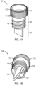
- a vial assembly can comprise a cap 100 including a first portion 110 , a threaded portion 120 , and a second portion 130 .
- the vial can, in non-limiting embodiments, comprise a tubular body having a cavity, an open end, and a closed end, which is discussed in more detail with reference to FIG. 2 .
- the first portion 110 can, in various embodiments, be configured to abut a lip defining an opening of the tube or vial to be sealed.
- the open end of the tubular body can comprise an aperture having, for example, a substantially circular shape.
- the diameter of the first cap portion 110 can, in some embodiments, be substantially equal to the diameter of the aperture defined lip. According to such an embodiment, the first portion 110 of the cap can rest atop the lip to seal the opening.
- the first portion 110 can have a diameter slightly larger than the diameter of the vial opening, such that the first portion surrounds the lip, e.g., fitting snugly around the vial lip to seal the opening.
- the first portion 110 can comprise a bottom surface 116 configured to contact the vial lip, and an upper portion 112 .
- the upper portion 112 can comprise an outer surface having one or more textural elements 114 .
- all or a portion of the outer surface may be textured to improve gripping ease when handling, closing, and/or opening the vial assembly.
- the outer surface of the upper portion 112 can be ribbed.
- portions of the outer surface of the upper portion 112 can be textured, e.g., one or more regions of textured surface, such as strips or grips for finger placement.
- the threaded portion 120 of the cap 100 can be contiguous with the first portion 110 and can comprise at least one threaded external surface 122 capable of mating or coupling with an internal surface of the tubular body.
- at least a portion of the internal surface of the tubular body can comprise threading, which can match the threading on an external surface of the threaded portion 120 of the cap 100 .
- threading and “threading” and variations thereof are intended to denote alternating raised and recessed sections generally defining an upward or downward spiral motion, e.g., such that the cap can be screwed or rotated on and off the tubular body.
- At least a portion of the threaded portion 120 of the cap 100 can engage at least a portion of threading located on an internal surface of the tubular body such that the cap can be rotated or screwed on and off and/or tightened or loosened by a rotating motion.
- the threaded portion 120 can comprise a hollow, substantially cylindrical shape having an opening 124 .
- Such an opening may provide for additional volume in the vial for sample storage, e.g., a liquid sample can fill all or a portion of the hollow internal volume of the threaded portion.
- the threaded portion 120 can be a solid cylindrical piece.
- the second portion 130 can be contiguous with the first and/or threaded portion of the cap and can protrude from the second portion at least partially into a cavity defined by the tubular body (in which the sample is placed).
- the second portion 130 can be attached to the bottom surface 116 of the first portion 110 , extending through the hollow threaded portion 120, and protruding from the threaded portion downward into the cavity of the vial.
- the second portion 130 can be attached to the threaded portion 120 and can protrude from the threaded portion into the cavity of the vial.
- the second portion can have any shape.
- the second portion can be flat or rounded, straight or curved, wavy, orthoganol or conical, just to name a few operative shapes.
- the second portion can have smooth or non-smooth surfaces.
- the bottom of the second portion can be flat or rounded.
- the second portion 130 can have a substantially flat shape, such as a square or rectangular shape, and may have a length and/or width larger than its thickness. Of course other shapes and configurations, such as rounded shapes or edges, are envisioned as falling within the scope of the disclosure.
- the second portion may be a solid piece and may not serve as a conduit into the cavity, such as a needle or other conduit for adding or removing samples from the cavity.
- the second portion 130 may be substantially flat or planar, e.g., not concave or convex.
- the second portion 130 can be envisioned as a "key" that can engage a frozen sample in a manner similar to a flat screwdriver engaging a slot in the top of a screw.
- the second portion can have any three dimensional shape, such as an "X" shape, like a Philips-head screwdriver, or a star shape.
- the second portion 130 can be at least partially immersed or submerged in the liquid within the cavity.
- the sample Upon freezing, the sample will form a complementary shape surrounding the second portion, such as a male/female pairing, e.g., a mated protrusion and a recess.
- a male/female pairing e.g., a mated protrusion and a recess.
- the second portion 130 can extend into the cavity to a distance equal to at least about 10% of the length of the cavity, such as at least about 20%, at least about 30%, at least about 40%, or at least about 50% of the cavity length, including all ranges and subranges therebetween.
- the second portion 130 protrudes or extends further into the cavity, engagement between the second portion 130 and the frozen sample can be enhanced; however, the increased length can also result in less volume available for sample filling in the cavity.
- a thicker piece can provide additional structural rigidity but likewise takes up additional space within the cavity. It is within the ability of one skilled in the art to weight these considerations when selecting a length, width, and/or thickness for the second portion 130 .
- Non-limiting exemplary dimensions for the second portion may include, for example, a length and/or width ranging from about 0.25 cm to about 3 cm, such as from about 0.5 cm to about 2.5 cm, from about 0.75 cm to about 2 cm, or from about 1 cm to about 1.5 cm, including all ranges and subranges therebetween.
- Suitable thicknesses include, for instance, from about 0.05 cm to about 0.3 cm, such as from about 0.1 cm to about 0.25 cm, from about 0.125 cm to about 0.2 cm, or from about 0.1 cm to about 0.15 cm, including all ranges and subranges therebetween.
- these dimensions can vary as desired or as appropriate depending e.g., on the size of the cryotube employed.
- the second portion 130 or "key” can include one or more apertures or openings (not illustrated), such as a hole spanning its thickness.
- an aperture can further engage the frozen pellet, e.g., a liquid sample can fill the aperture and solidify upon freezing to occupy the aperture and positively engage the second portion 130 . Additional engagement between the frozen sample and the aperture can further provide a way to pull the sample from the vial or transport the sample after removal, as the pellet can remain engaged to the cap.
- Such an embodiment can reduce the risk of dropping the frozen sample during and/or after removal from the tube.
- the aperture disclosed herein does not affect the seal of the vial assembly, e.g., it is not an aperture or opening providing access into the cavity when the assembly is in a closed position.
- the aperture is also distinguishable from an aperture spanning the length of the second portion, such as a conduit in a needle or other similar aperture.
- the apparatuses disclosed herein can comprise a tubular body or vial 200 comprising an open end 210 , a closed end 220 , and a cavity 230.
- the open end 210 can comprise a lip 212 defining the opening to be sealed by the cap 100 .
- the lip 212 can engage, in some embodiments, the bottom surface 116 of the first portion 110 of the cap, such that in the closed position the bottom surface 116 abuts the lip 212 .
- a seal or sealing material 240 can be provided between the lip 212 and the bottom surface 116 to enhance the integrity of the seal.
- Suitable sealing materials can include, for example, thermoplastic and thermoset elastomers, such as silicon-based polymers (e.g., polydimethylsiloxane) or multi-block elastomer alloys (e.g., Versaflex TM products from PolyOne, such as CL2250 or HC MT222), to name a few.
- a sealing ring can be placed around the lip 212 .
- the cavity 230 can comprise an internal surface 232 .
- the internal surface 232 can comprise at least one threaded portion 234 proximate the open end 210 of the tubular body 200 .
- the remainder of the internal surface extending down to the closed end 220 can comprise an unthreaded portion 236 according to certain non-limiting embodiments (as illustrated in FIG. 2 ).
- the threaded portion 234 can have a longer length or the entire internal surface 232 of the cavity 230 can be threaded.
- the diameter of the threaded portion 234 can be greater than the diameter of the unthreaded portion 236 .
- the diameter of the threaded portion can be at least about 5% greater than the diameter of the unthreaded portion, such as at least about 10%, 15%, 20%, or 25% greater, including all ranges and subranges therebetween.
- Such embodiments may promote the ease of removal of the frozen sample from the vial.
- the sample can be frozen into the grooves of the threading, thereby creating a complimentary threading on the surface of the frozen pellet, which can create a mechanism by which the frozen sample can be rotated out of the vial.
- potential issues associated with "undercutting" or obstruction of the sample upon removal may be avoided, as the sample having a diameter equal to that of the unthreaded portion need not pass through a slightly narrower threaded portion to exit the vial.
- undercutting can be reduced or avoided by configuring the cavity to have an unthreaded portion and a threaded portion, wherein the unthreaded portion has a smaller diameter than the threaded portion.
- the diameter of the unthreaded portion can be less than or equal to the inside diameter of the threaded portion at its narrowest point, e.g., the distance between two raised thread surfaces, as opposed to greater than or equal to the outside diameter of the threaded portion at its widest point, e.g., the distance between two recessed thread surfaces.
- the closed end 220 of the tubular body 200 is illustrated in FIG. 3 and will be discussed in more detail with reference to this cross-sectional image.
- the closed end 220 can have a substantially rounded bottom 224 , although other shapes are possible and envisioned as falling within the scope of the disclosure.
- the closed end can have substantially similar properties to the remainder of the tubular body, e.g., wall thickness, rigidity, etc.
- the closed end 220 can be equipped with one or more features for promoting disengagement of the frozen sample from the vial. For instance, various portions of the closed end 220 can have a reduced wall thickness to enhance malleability of the tube in those locations.
- the bottom region 224 of the closed end may have a reduced wall thickness, which may facilitate bending, flexing, and/or pinching of the tube in this location to encourage dislodgment of the frozen sample from the tube.
- the closed end may be as described in co-pending and co-owned US patent application no. 62255627 .
- the vial assembly can be provided with additional side walls or flanges 250 attached to the tubular body 200 proximate the closed end 220 .
- the flanges 250 can serve multiple functions, e.g., providing a stand for the vial and/or a means for storing the vial within a rack or stand.
- the flanges 250 can be configured to bend inwardly upon application of force to apply pressure to the bottom 224 of the closed end 220 .
- the flanges 250 may be used as a hinge to pinch or otherwise impinge on the bottom 224 of the closed end 220 .
- the wall of the vial can be thinned in a second location 226 proximate the attachment point of the flange 250 to the tubular body 200 . Thinning of the tube wall in this location may enhance the ability of the flanges 250 to hinge inwardly.
- the flanges 250 can be equipped with gussets or inward protrusions 252 that can increase the force applied to the bottom 224 of the closed end 220 . Force applied to the flanges 250 can be redirected by the gussets 252 to the bottom of the vial, e.g., providing an upward force pushing into the bottom of the vial to dislodge the pellet.
- FIG. 4 illustrates a perspective view of the exterior of a vial assembly according to various aspects of the disclosure.
- the first portion 110 of the cap 100 is visible, which is engaged with the open end of the tubular body 200 via seal 240 .
- the threaded portion and second portion of the cap 100 are located inside the cavity of the tubular body 200 and therefore not visible in the closed position.
- the closed end 220 of the tubular body 220 is optionally equipped with flanges 250 for standing the vial upright and/or for disengaging the frozen sample from the vial.
- the flanges 250 can, in some embodiments, include a textured region 254 , which can be raised for enhanced gripping by a user during use (e.g., finger grips) and/or for insertion into a storage rack or block, or recessed for fitting into standard tube racks.
- a textured region 254 can be raised for enhanced gripping by a user during use (e.g., finger grips) and/or for insertion into a storage rack or block, or recessed for fitting into standard tube racks.
- the vial assemblies can be manufactured from any materials suitable for cryopreservation applications.
- Non-limiting exemplary materials can include, for example, plastics such as polyolefins synthetic and thermoplastic polymers, such as polypropylene, polyethylene, polystyrene, polyester, polycarbonate, and polytetrafluoroethylene, to name a few.
- the tubular body and cap of the vial assembly can comprise the same or different materials.
- the cap may comprise a substantially rigid material, whereas the tube can comprise a rigid or flexible material.
- the tubular body can comprise a material which, at a sufficiently high thickness can provide rigidity at the open end, but at a sufficiently low thickness can provide flexibility at the closed end of the tube.
- the thickness of the wall of the tubular body proximate the open end can range from about 0.05 cm to about 0.2 cm, such as from about 0.06 cm to about 0.15 cm, or from about 0.075 cm to about 0.125 cm, including all ranges and subranges therebetween, whereas the thickness of the wall of the tubular body proximate the closed end can range from about 0.025 cm to about 0.1 cm, such as from about 0.03 cm to about 0.075 cm, from about 0.04 cm to about 0.07 cm, or from about 0.05 cm to about 0.06 cm, including all ranges and subranges therebetween.
- Additional optional features can be included in the vial assembly disclosed herein, e.g. for improved ease of handling, heat transfer, and/or sealing of the vial.
- Methods disclosed herein can include methods for preparing a frozen sample in a vial assembly and methods for removing a frozen sample from a vial assembly.
- Methods for preparing and/or storing frozen samples can include introducing a liquid sample into a cavity of a tubular body; engaging an open end of the tubular body with a cap to form a sealed vial assembly, wherein the cap comprises a first portion configured to abut a lip of the open end of the tubular body, a threaded portion configured to couple to at least a portion of threading on an internal surface of the tubular body, and a second portion protruding from the threaded portion and extending into the cavity of the tubular body, wherein when the cap is engaged with the open end of the tubular body the second potion of the cap is at least partially immersed in the liquid sample; and freezing the sealed vial assembly.
- Methods for removing frozen samples from a vial assembly can include rotating the cap of the vial assembly to disengage a threaded portion of the cap from threading on an internal surface of the tubular body, wherein rotating the cap causes a second portion of the cap in physical contact with the frozen sample to rotate the frozen sample and at least partially disengage the frozen sample from the internal surface of the tubular body; removing the cap; and removing the frozen sample from the vial assembly.
- rotating the cap of the vial assembly can include rotating the cap of the vial assembly to disengage a threaded portion of the cap from threading on an internal surface of the tubular body, wherein rotating the cap causes a second portion of the cap in physical contact with the frozen sample to rotate the frozen sample and at least partially disengage the frozen sample from the internal surface of the tubular body; removing the cap; and removing the frozen sample from the vial assembly.
- a frozen sample e.g. comprising a biological sample such as cells or tissues
- a vial assembly disclosed herein.
- a predetermined amount of a liquid sample can be poured into the open end of the tubular body.
- the cap can then be coupled to the open end of the tubular body by rotating the cap such that the threading on the second portion engages at least a portion of the threading on the internal surface of the tubular body. Rotation can be carried out until the cap is snugly fit to the tubular body, for instance, until a bottom surface of the top portion of the cap abuts the lip of the tubular body or abuts a seal disposed between the lip and the top portion of the cap. In this "closed" position, the second portion of the cap can extend into the tubular body cavity containing the liquid sample.
- the liquid sample can be added, in various embodiments, in an amount sufficient to at least partially contact the second portion of the cap in the closed position.
- the second portion can be at least partially immersed in the liquid sample, e.g., at least about 5% of the second portion can be immersed, such as at least about 10%, 20%, 30%, 40%, 50%, 60%, 70%, 80%, 90%, or even 100% of the second portion is immersed in the liquid sample.
- the threaded portion of the cap may be a hollow cylindrical shape and the liquid sample may at least partially occupy the internal volume of the threaded portion.
- the vial assembly and sample contained therein can be frozen, e.g., at a temperature below the freezing point of the sample.
- the vial assembly can, for instance, be frozen in an upright position such that the liquid is in contact with a bottom internal surface of the cavity.
- the vial assembly can also be frozen in an inverted position, such that the liquid is in contact with a top internal surface of the cavity and/or the bottom surface of the top portion of the cap.
- the sample can be frozen such that the second portion of the cap is at least partially immersed in the liquid sample.
- the sample thus frozen can take on a complementary shape relative to the second portion of the cap.
- Removal of the frozen sample from the vial assembly can be achieved by disengaging the cap from the tubular body. Twisting or rotating of the cap can cause the second portion of the cap in contact with the frozen sample to engage and rotate the frozen sample within the tubular body. The rotating action can serve to loosen the frozen sample from the internal surfaces of the tubular body such that the sample can be more easily ejected from the vial assembly.
- the internal surface of the tubular body may comprise threading extending from the open end to the closed end and the cap may be rotated repeatedly to "unscrew" the sample from the vial, e.g., disengage the sample from the threading in the tubular body.
- the second portion of the cap can act in a fashion similar to a screwdriver engaging a top slot of a screw.
- the frozen sample can be further dislodged by applying pressure to the closed end of the tubular body, which may be configured, in some embodiments, to compress at least partially upon the application of force.
- the closed end of the tubular body can be compressed by squeezing two or more flanges proximate the closed end. The flanges can apply inward and/or upward force to the bottom of the tubular body to push the frozen sample out of the vial.
- the frozen sample can be pulled from the vial using the cap.
- the second portion of the cap may be equipped with one or more apertures into which the sample has frozen to further engage the second portion with the sample. The attachment between the cap and the frozen sample may allow the user to pull the sample from the vial by displacing the cap from the tubular body for a distance sufficient to fully dislodge the sample.
- Ranges can be expressed herein as from “about” one particular value, and/or to “about” another particular value. When such a range is expressed, examples include from the one particular value and/or to the other particular value. Similarly, when values are expressed as approximations, by use of the antecedent "about,” it will be understood that the particular value forms another aspect. It will be further understood that the endpoints of each of the ranges are significant both in relation to the other endpoint, and independently of the other endpoint.
Abstract
Description
- This application claims the benefit of priority under 35 U.S.C. § 119 of
U.S. Provisional Application Serial No. 62/255,633 filed on November 16, 2015 - The present disclosure relates generally to cryopreseravation devices, and more specifically to cryogenic vial assemblies for preparing and storing frozen samples, and methods for removing frozen samples from such vial assemblies.
- Biological samples such as cells and tissues are often cryopreserved to extend their viability and usefulness for a variety of applications. For example, the cryopreservation process can involve placing a biological sample into an aqueous solution containing electrolytes and/or cryoprotectants and lowering the temperature of the solution to below its freezing point. Biological samples are often stored in vials which can be sealed and frozen, e.g., by immersion in liquid nitrogen. It can be important to maintain the sample integrity during the filling, storage, and retrieval stages, as contamination can render a biological sample useless for scientific research or other applications.
- Vial leakage, which can be caused by a failure of the seal between the vial and the cap, can be a contributing factor to sample contamination. Sample contamination can also occur during thawing of the sample prior to its removal from the vial. For instance, cryogenic vials are often placed in a warm bath or heated block to partially or completely defrost the sample for ease of removal. However, samples can become contaminated or lose part of their viability during this process due to liquid immersion and/or elevated temperatures. The sample may also become overstressed due to excessive heating at the vial wall surface which can further damage the sample.
- Removal of samples in the frozen state without thawing may reduce the risk of sample contamination and/or damage. However, it can be difficult to remove the frozen pellet from the vial due to adhesion of the sample to the vial walls and/or inability to grip and/or exert a force on the sample. Accordingly, it would be advantageous to provide vial assemblies from which frozen samples can be more easily discharged while also maintaining an acceptable seal integrity for preventing sample contamination. It would also be advantageous to provide methods for preparing frozen samples which can be more easily discharged from a vial and methods for removing frozen samples from vials without the need for thawing prior to removal.
- The disclosure relates, in various embodiments, to vial assemblies comprising a tubular body comprising a cavity, an open end comprising a lip, and a closed end, wherein an internal surface of the tubular body proximate the open end comprises threading; and a cap configured to couple to the open end of the tubular body, wherein the cap comprises (a) a first portion configured to abut the lip of the open end; (b) a threaded portion configured to couple to at least a portion of the threading on the internal surface of the tubular body; and (c) a second portion protruding from the threaded portion and extending into the cavity of the tubular body.
- Also disclosed herein are methods for preparing and storing frozen samples in a vial assembly, the methods comprising introducing a liquid sample into a cavity of a tubular body; engaging an open end of the tubular body with a cap to form a sealed vial assembly, wherein the cap comprises a first portion configured to abut a lip of the open end of the tubular body, a threaded portion configured to couple to at least a portion of threading on an internal surface of the tubular body, and a second portion protruding from the threaded portion and extending into the cavity of the tubular body, wherein when the cap is engaged with the open end of the tubular body the second potion of the cap is at least partially immersed in the liquid sample; and freezing the sealed vial assembly.
- Further disclosed herein are methods for removing frozen samples from a vial assembly comprising a tubular body and a cap, the methods comprising rotating the cap of the vial assembly to disengage a threaded portion of the cap from threading on an internal surface of the tubular body, wherein rotating the cap causes a second portion of the cap in physical contact with the frozen sample to rotate the frozen sample and at least partially disengage the frozen sample from the internal surface of the tubular body; removing the cap; and removing the frozen sample from the vial assembly.
- Vial assemblies disclosed herein may provide a user with the ability to loosen and remove a frozen sample from a vial without thawing the sample beforehand. Methods for removing frozen samples from the vial assemblies disclosed herein may have improved consistency and/or repeatability, thereby saving the user time and/or decreasing variability from sample to sample due to varying sample removal conditions, e.g., differing time and/or temperature used to thaw a sample. It should be noted, however, that one or more of such benefits may not be present according to various embodiments of the disclosure, yet such embodiments are intended to fall within the scope of the disclosure.
- The disclosure provides, in an aspect (1), a vial assembly comprising: a tubular body comprising a cavity, an open end comprising a lip, and a closed end, wherein an internal surface of the tubular body proximate the open end comprises threading; and a cap configured to couple to the open end of the tubular body, wherein the cap comprises: a first portion configured to abut the lip of the open end; a threaded portion configured to couple to at least a portion of the threading on the internal surface of the tubular body; and a second portion protruding from the threaded portion and extending into the cavity of the tubular body. In an aspect (2), the disclosure provides the vial assembly of aspect 1, wherein the cap is configured to couple to the open end of the tubular body by rotation to engage the threaded portion of the cap to the threading on the internal surface of the tubular body. In an aspect (3), the disclosure provides the vial assembly of aspect 1 or 2, wherein the tubular body comprises a first portion having an internal surface comprising threading and a second portion having an internal surface not comprising threading. In an aspect (4), the disclosure provides the vial assembly of any one of aspects 1-3, wherein a diameter of the first portion of the tubular body is greater than a diameter of the second portion of the tubular body. In an aspect (5), the disclosure provides the vial assembly of any one of claims 1- 4, wherein the internal surface of the tubular body comprising threading extends from the open end to the closed end of the tubular body. In an aspect (6), the disclosure provides the vial assembly of any one of aspects 1- 5, wherein the first portion comprises an upper portion having a height extending above the lip of the open end, the upper portion comprising a textured surface. In an aspect (7), the disclosure provides the vial assembly of any one of aspects 1-6, wherein the first portion is configured to seal the open end of the tubular body. In an aspect (8), the disclosure provides he vial assembly of any one of aspects 1- 7, further comprising a sealing member between the first portion and the lip of the tubular body. In an aspect (9), the disclosure provides the vial assembly of of any one of aspects 1-8, wherein the threaded portion of the cap comprises a hollow cylinder having an external threaded surface. In an aspect (10), the disclosure provides the vial assembly of of any one of aspects 1-9, wherein the second portion comprises a substantially flat piece having at least one dimension chosen from length or width greater than a thickness of the substantially flat piece. In an aspect (11), the disclosure provides the vial assembly of aspect 10, wherein the second portion comprises at least one aperture extending across the thickness of the second portion. In an aspect (12), the disclosure provides the vial assembly of of any one of aspects 1-11, wherein the tubular body comprises a tube wall and wherein at least a first portion of the tube wall proximate the closed end has a thickness less than a thickness of a second portion of the tube wall proximate the open end. In an aspect (13) the disclosure provides the vial assembly of aspect 12, further comprising at least two flanges proximate the closed end of the tubular body, wherein the flanges are configured to hinge inwardly and apply force to the closed end of the tubular body. In an aspect (14), the disclosure provides the vial assembly of aspect 13, wherein the flanges further comprise at least one gusset configured to apply an upward force to the closed end of the tubular body.
- In a further aspect (15), the disclosure provides a method for preparing a frozen sample, comprising: introducing a liquid sample into a cavity of a tubular body; engaging an open end of the tubular body with a cap to form a sealed vial assembly, wherein the cap comprises: a first portion configured to abut a lip of the open end of the tubular body; a threaded portion configured to couple to at least a portion of threading on an internal surface of the tubular body; and a second portion protruding from the threaded portion and extending into the cavity of the tubular body; wherein when the cap is engaged with the open end of the tubular body the second portion of the cap is at least partially immersed in the liquid sample; and freezing the sealed vial assembly. In an aspect (16), the disclosure provides the method of aspect 15, wherein engaging the open end of the tubular body with the cap comprises rotating the cap to engage the threaded portion of the cap to the threading on the internal surface of the tubular body. In an aspect (17), the disclosure provides the method of aspect 15, wherein the liquid sample comprises a biological sample. In an aspect (18), the disclosure provides a method for removing a frozen sample from a vial assembly comprising a tubular body and a cap, the method comprising: rotating the cap of the vial assembly to disengage a threaded portion of the cap from threading on an internal surface of the tubular body; wherein rotating the cap causes a second portion of the cap in physical contact with the frozen sample to rotate the frozen sample and at least partially disengage the frozen sample from the internal surface of the tubular body; removing the cap; and removing the frozen sample from the vial assembly. In an aspect (19) the disclosure provides the method of aspect 18, further comprising applying pressure to at least a portion of a closed end of the tubular body, wherein the closed end is configured to compress at least partially upon the application of pressure. In an aspect (20), the disclosure provides the method of aspect 19, wherein applying pressure to at least a portion of the closed end of the tubular body comprises depressing two or more flanges proximate the closed end. In an aspect (21), the disclosure provides the method of aspect 19, wherein the frozen sample is at least partially attached to the second portion of the cap and removing the frozen sample comprises pulling the cap from the tubular body for a distance sufficient to fully disengage the frozen sample from the tubular body. In an aspect (22), t the disclosure provides the method of aspect 19, wherein the threading on the internal surface of the tubular body extends from the open end to the closed end of the tubular body and wherein removing the frozen sample comprises rotating the cap for a number of revolutions sufficient to disengage the frozen sample from the threading of the tubular body.
- Additional features and advantages of the invention will be set forth in the detailed description which follows, and in part will be readily apparent to those skilled in the art from that description or recognized by practicing the invention as described herein, including the detailed description which follows, the claims, and the appended drawings.
- It is to be understood that both the foregoing general description and the following detailed description present various embodiments of the disclosure, and are intended to provide an overview or framework for understanding the nature and character of the claims. The accompanying drawings are included to provide a further understanding of the disclosure, and are incorporated into and constitute a part of this specification. The drawings illustrate various embodiments of the disclosure and together with the description serve to explain the principles and operations of the invention.
- The following detailed description can be best understood when read in conjunction with the following drawings, in which:
-
FIGS. 1A-B are perspective views of a vial cap according to embodiments disclosed herein; -
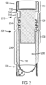
FIG. 2 is a cross-sectional view of a vial assembly according to various disclosed embodiments; -
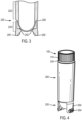
FIG. 3 is a cross-sectional view of the bottom of a vial assembly according to certain embodiments disclosed herein; and -
FIG. 4 is a perspective view of a vial assembly according to embodiments disclosed herein. - Disclosed herein are vial assemblies comprising a tubular body comprising a cavity, an open end comprising a lip, and a closed end, wherein an internal surface of the tubular body proximate the open end comprises threading; and a cap configured to couple to the open end of the tubular body, wherein the cap comprises (a) a first portion configured to abut the lip of the open end; (b) a threaded portion configured to couple to at least a portion of the threading on the internal surface of the tubular body; and (c) a second portion protruding from the threaded portion and extending into the cavity of the tubular body.
- Embodiments of the disclosure will be discussed with reference to
FIGS. 1- 4, which illustrate various aspects of a vial assembly according to non-limiting embodiments of the disclosure. The following general description is intended to provide an overview of the claimed apparatus and various aspects will be more specifically discussed throughout the disclosure with reference to the non-limiting embodiments, these embodiments being interchangeable with one another within the context of the disclosure. - As demonstrated in
FIGS. 1A-B, which are perspective views of the side and bottom of a vial cap according to various embodiments of the disclosure, respectively, a vial assembly can comprise acap 100 including afirst portion 110, a threadedportion 120, and asecond portion 130. Various aspects of the cap will be discussed with reference to the vial to which the cap is configured to mate or couple. The vial can, in non-limiting embodiments, comprise a tubular body having a cavity, an open end, and a closed end, which is discussed in more detail with reference toFIG. 2 . - The
first portion 110 can, in various embodiments, be configured to abut a lip defining an opening of the tube or vial to be sealed. The open end of the tubular body can comprise an aperture having, for example, a substantially circular shape. The diameter of thefirst cap portion 110 can, in some embodiments, be substantially equal to the diameter of the aperture defined lip. According to such an embodiment, thefirst portion 110 of the cap can rest atop the lip to seal the opening. In other embodiments, thefirst portion 110 can have a diameter slightly larger than the diameter of the vial opening, such that the first portion surrounds the lip, e.g., fitting snugly around the vial lip to seal the opening. - In certain embodiments, the
first portion 110 can comprise abottom surface 116 configured to contact the vial lip, and anupper portion 112. Theupper portion 112 can comprise an outer surface having one or moretextural elements 114. For example, all or a portion of the outer surface may be textured to improve gripping ease when handling, closing, and/or opening the vial assembly. In certain embodiments, the outer surface of theupper portion 112 can be ribbed. According to additional embodiments, portions of the outer surface of theupper portion 112 can be textured, e.g., one or more regions of textured surface, such as strips or grips for finger placement. - The threaded
portion 120 of thecap 100 can be contiguous with thefirst portion 110 and can comprise at least one threadedexternal surface 122 capable of mating or coupling with an internal surface of the tubular body. For example, at least a portion of the internal surface of the tubular body can comprise threading, which can match the threading on an external surface of the threadedportion 120 of thecap 100. As used herein, the terms "threaded" and "threading" and variations thereof are intended to denote alternating raised and recessed sections generally defining an upward or downward spiral motion, e.g., such that the cap can be screwed or rotated on and off the tubular body. Thus, at least a portion of the threadedportion 120 of thecap 100 can engage at least a portion of threading located on an internal surface of the tubular body such that the cap can be rotated or screwed on and off and/or tightened or loosened by a rotating motion. - According to various embodiments, the threaded
portion 120 can comprise a hollow, substantially cylindrical shape having anopening 124. Such an opening may provide for additional volume in the vial for sample storage, e.g., a liquid sample can fill all or a portion of the hollow internal volume of the threaded portion. In other embodiments (not illustrated), the threadedportion 120 can be a solid cylindrical piece. - The
second portion 130 can be contiguous with the first and/or threaded portion of the cap and can protrude from the second portion at least partially into a cavity defined by the tubular body (in which the sample is placed). In the case of a hollow threadedportion 120, as depicted inFIGS. 1A-B, thesecond portion 130 can be attached to thebottom surface 116 of thefirst portion 110, extending through the hollow threadedportion 120, and protruding from the threaded portion downward into the cavity of the vial. In other embodiments, such as in the case of a solid threadedportion 120, thesecond portion 130 can be attached to the threadedportion 120 and can protrude from the threaded portion into the cavity of the vial. - According to non-limiting embodiments, the second portion can have any shape. For example, the second portion can be flat or rounded, straight or curved, wavy, orthoganol or conical, just to name a few operative shapes. The second portion can have smooth or non-smooth surfaces. The bottom of the second portion can be flat or rounded. As shown in
FIGS. 1A-B , thesecond portion 130 can have a substantially flat shape, such as a square or rectangular shape, and may have a length and/or width larger than its thickness. Of course other shapes and configurations, such as rounded shapes or edges, are envisioned as falling within the scope of the disclosure. According to various aspects, the second portion may be a solid piece and may not serve as a conduit into the cavity, such as a needle or other conduit for adding or removing samples from the cavity. In additional aspects, thesecond portion 130 may be substantially flat or planar, e.g., not concave or convex. In certain embodiments, thesecond portion 130 can be envisioned as a "key" that can engage a frozen sample in a manner similar to a flat screwdriver engaging a slot in the top of a screw. Or, for example, the second portion can have any three dimensional shape, such as an "X" shape, like a Philips-head screwdriver, or a star shape. - For instance, when liquid is added to the vial and the
cap 100 is screwed on to seal the vial, thesecond portion 130 can be at least partially immersed or submerged in the liquid within the cavity. Upon freezing, the sample will form a complementary shape surrounding the second portion, such as a male/female pairing, e.g., a mated protrusion and a recess. Thus, when the frozen sample is to be removed, the rotating motion of thecap 100 can cause thesecond portion 130 to engage with the frozen sample and rotate the sample pellet within the vial. - By way of a non-limiting example, the
second portion 130 can extend into the cavity to a distance equal to at least about 10% of the length of the cavity, such as at least about 20%, at least about 30%, at least about 40%, or at least about 50% of the cavity length, including all ranges and subranges therebetween. When thesecond portion 130 protrudes or extends further into the cavity, engagement between thesecond portion 130 and the frozen sample can be enhanced; however, the increased length can also result in less volume available for sample filling in the cavity. Similarly, a thicker piece can provide additional structural rigidity but likewise takes up additional space within the cavity. It is within the ability of one skilled in the art to weight these considerations when selecting a length, width, and/or thickness for thesecond portion 130. Non-limiting exemplary dimensions for the second portion may include, for example, a length and/or width ranging from about 0.25 cm to about 3 cm, such as from about 0.5 cm to about 2.5 cm, from about 0.75 cm to about 2 cm, or from about 1 cm to about 1.5 cm, including all ranges and subranges therebetween. Suitable thicknesses include, for instance, from about 0.05 cm to about 0.3 cm, such as from about 0.1 cm to about 0.25 cm, from about 0.125 cm to about 0.2 cm, or from about 0.1 cm to about 0.15 cm, including all ranges and subranges therebetween. Of course these dimensions can vary as desired or as appropriate depending e.g., on the size of the cryotube employed. - In additional embodiments, the
second portion 130 or "key" can include one or more apertures or openings (not illustrated), such as a hole spanning its thickness. In these aspects, such an aperture can further engage the frozen pellet, e.g., a liquid sample can fill the aperture and solidify upon freezing to occupy the aperture and positively engage thesecond portion 130. Additional engagement between the frozen sample and the aperture can further provide a way to pull the sample from the vial or transport the sample after removal, as the pellet can remain engaged to the cap. Such an embodiment can reduce the risk of dropping the frozen sample during and/or after removal from the tube. It is to be understood that the aperture disclosed herein does not affect the seal of the vial assembly, e.g., it is not an aperture or opening providing access into the cavity when the assembly is in a closed position. The aperture is also distinguishable from an aperture spanning the length of the second portion, such as a conduit in a needle or other similar aperture. - As depicted in
FIG. 2 , which is a cross-sectional view of an exemplary vial assembly, the apparatuses disclosed herein can comprise a tubular body orvial 200 comprising anopen end 210, aclosed end 220, and acavity 230. Theopen end 210 can comprise a lip 212 defining the opening to be sealed by thecap 100. The lip 212 can engage, in some embodiments, thebottom surface 116 of thefirst portion 110 of the cap, such that in the closed position thebottom surface 116 abuts the lip 212. Optionally, a seal or sealingmaterial 240 can be provided between the lip 212 and thebottom surface 116 to enhance the integrity of the seal. Suitable sealing materials can include, for example, thermoplastic and thermoset elastomers, such as silicon-based polymers (e.g., polydimethylsiloxane) or multi-block elastomer alloys (e.g., Versaflex™ products from PolyOne, such as CL2250 or HC MT222), to name a few. In some embodiments, a sealing ring can be placed around the lip 212. - According to various aspects, the
cavity 230 can comprise aninternal surface 232. Theinternal surface 232 can comprise at least one threadedportion 234 proximate theopen end 210 of thetubular body 200. The remainder of the internal surface extending down to theclosed end 220 can comprise an unthreadedportion 236 according to certain non-limiting embodiments (as illustrated inFIG. 2 ). In other embodiments, although not illustrated, the threadedportion 234 can have a longer length or the entireinternal surface 232 of thecavity 230 can be threaded. In still further aspects, when thecavity 230 comprises threaded and unthreaded portions, the diameter of the threadedportion 234 can be greater than the diameter of the unthreadedportion 236. For instance, the diameter of the threaded portion can be at least about 5% greater than the diameter of the unthreaded portion, such as at least about 10%, 15%, 20%, or 25% greater, including all ranges and subranges therebetween. - Such embodiments may promote the ease of removal of the frozen sample from the vial. In the case of a continuously threaded internal surface, the sample can be frozen into the grooves of the threading, thereby creating a complimentary threading on the surface of the frozen pellet, which can create a mechanism by which the frozen sample can be rotated out of the vial. Additionally, by threading the entire inner surface, potential issues associated with "undercutting" or obstruction of the sample upon removal may be avoided, as the sample having a diameter equal to that of the unthreaded portion need not pass through a slightly narrower threaded portion to exit the vial. In other embodiments, undercutting can be reduced or avoided by configuring the cavity to have an unthreaded portion and a threaded portion, wherein the unthreaded portion has a smaller diameter than the threaded portion. For example, the diameter of the unthreaded portion can be less than or equal to the inside diameter of the threaded portion at its narrowest point, e.g., the distance between two raised thread surfaces, as opposed to greater than or equal to the outside diameter of the threaded portion at its widest point, e.g., the distance between two recessed thread surfaces.
- The
closed end 220 of thetubular body 200 is illustrated inFIG. 3 and will be discussed in more detail with reference to this cross-sectional image. As depicted inFIG. 3 , theclosed end 220 can have a substantially roundedbottom 224, although other shapes are possible and envisioned as falling within the scope of the disclosure. The closed end can have substantially similar properties to the remainder of the tubular body, e.g., wall thickness, rigidity, etc. In other embodiments, and as illustrated inFIG. 3 , theclosed end 220 can be equipped with one or more features for promoting disengagement of the frozen sample from the vial. For instance, various portions of theclosed end 220 can have a reduced wall thickness to enhance malleability of the tube in those locations. Whereas anupper portion 222 of theclosed end 220 can have a thicker sidewall substantially matching the rest of the vial, thebottom region 224 of the closed end may have a reduced wall thickness, which may facilitate bending, flexing, and/or pinching of the tube in this location to encourage dislodgment of the frozen sample from the tube. For example, the closed end may be as described in co-pending and co-ownedUS patent application no. 62255627 - In some embodiments, the vial assembly can be provided with additional side walls or
flanges 250 attached to thetubular body 200 proximate theclosed end 220. Theflanges 250 can serve multiple functions, e.g., providing a stand for the vial and/or a means for storing the vial within a rack or stand. Additionally, theflanges 250 can be configured to bend inwardly upon application of force to apply pressure to thebottom 224 of theclosed end 220. For instance, theflanges 250 may be used as a hinge to pinch or otherwise impinge on thebottom 224 of theclosed end 220. - Further features may be added to the
tubular body 200 and/or theflanges 250 to enhance the ability to dislodge the frozen sample from the vial. In some embodiments, the wall of the vial can be thinned in asecond location 226 proximate the attachment point of theflange 250 to thetubular body 200. Thinning of the tube wall in this location may enhance the ability of theflanges 250 to hinge inwardly. Additionally, theflanges 250 can be equipped with gussets or inward protrusions 252 that can increase the force applied to thebottom 224 of theclosed end 220. Force applied to theflanges 250 can be redirected by the gussets 252 to the bottom of the vial, e.g., providing an upward force pushing into the bottom of the vial to dislodge the pellet. -
FIG. 4 illustrates a perspective view of the exterior of a vial assembly according to various aspects of the disclosure. In the closed position, thefirst portion 110 of thecap 100 is visible, which is engaged with the open end of thetubular body 200 viaseal 240. The threaded portion and second portion of thecap 100 are located inside the cavity of thetubular body 200 and therefore not visible in the closed position. Theclosed end 220 of thetubular body 220 is optionally equipped withflanges 250 for standing the vial upright and/or for disengaging the frozen sample from the vial. Theflanges 250 can, in some embodiments, include atextured region 254, which can be raised for enhanced gripping by a user during use (e.g., finger grips) and/or for insertion into a storage rack or block, or recessed for fitting into standard tube racks. - The vial assemblies, including the tubular bodies and caps thereof, can be manufactured from any materials suitable for cryopreservation applications. Non-limiting exemplary materials can include, for example, plastics such as polyolefins synthetic and thermoplastic polymers, such as polypropylene, polyethylene, polystyrene, polyester, polycarbonate, and polytetrafluoroethylene, to name a few. According to various embodiments, the tubular body and cap of the vial assembly can comprise the same or different materials. Additionally, the cap may comprise a substantially rigid material, whereas the tube can comprise a rigid or flexible material. In certain embodiments, the tubular body can comprise a material which, at a sufficiently high thickness can provide rigidity at the open end, but at a sufficiently low thickness can provide flexibility at the closed end of the tube. For example, according to various embodiments, the thickness of the wall of the tubular body proximate the open end can range from about 0.05 cm to about 0.2 cm, such as from about 0.06 cm to about 0.15 cm, or from about 0.075 cm to about 0.125 cm, including all ranges and subranges therebetween, whereas the thickness of the wall of the tubular body proximate the closed end can range from about 0.025 cm to about 0.1 cm, such as from about 0.03 cm to about 0.075 cm, from about 0.04 cm to about 0.07 cm, or from about 0.05 cm to about 0.06 cm, including all ranges and subranges therebetween.
- Additional optional features can be included in the vial assembly disclosed herein, e.g. for improved ease of handling, heat transfer, and/or sealing of the vial.
- Methods disclosed herein can include methods for preparing a frozen sample in a vial assembly and methods for removing a frozen sample from a vial assembly. Methods for preparing and/or storing frozen samples can include introducing a liquid sample into a cavity of a tubular body; engaging an open end of the tubular body with a cap to form a sealed vial assembly, wherein the cap comprises a first portion configured to abut a lip of the open end of the tubular body, a threaded portion configured to couple to at least a portion of threading on an internal surface of the tubular body, and a second portion protruding from the threaded portion and extending into the cavity of the tubular body, wherein when the cap is engaged with the open end of the tubular body the second potion of the cap is at least partially immersed in the liquid sample; and freezing the sealed vial assembly. Methods for removing frozen samples from a vial assembly can include rotating the cap of the vial assembly to disengage a threaded portion of the cap from threading on an internal surface of the tubular body, wherein rotating the cap causes a second portion of the cap in physical contact with the frozen sample to rotate the frozen sample and at least partially disengage the frozen sample from the internal surface of the tubular body; removing the cap; and removing the frozen sample from the vial assembly. Of course, it is to be understood that the features disclosed herein with respect to the vial assembly are intended to similarly apply to the methods disclosed herein, such that a method for preparing or removing the sample can employ or utilize one or more features described with respect to the vial assembly.
- According to various embodiments, a frozen sample, e.g. comprising a biological sample such as cells or tissues, can be introduced into a vial assembly disclosed herein. For instance, a predetermined amount of a liquid sample can be poured into the open end of the tubular body. The cap can then be coupled to the open end of the tubular body by rotating the cap such that the threading on the second portion engages at least a portion of the threading on the internal surface of the tubular body. Rotation can be carried out until the cap is snugly fit to the tubular body, for instance, until a bottom surface of the top portion of the cap abuts the lip of the tubular body or abuts a seal disposed between the lip and the top portion of the cap. In this "closed" position, the second portion of the cap can extend into the tubular body cavity containing the liquid sample.
- The liquid sample can be added, in various embodiments, in an amount sufficient to at least partially contact the second portion of the cap in the closed position. For instance, the second portion can be at least partially immersed in the liquid sample, e.g., at least about 5% of the second portion can be immersed, such as at least about 10%, 20%, 30%, 40%, 50%, 60%, 70%, 80%, 90%, or even 100% of the second portion is immersed in the liquid sample. According to certain embodiments, the threaded portion of the cap may be a hollow cylindrical shape and the liquid sample may at least partially occupy the internal volume of the threaded portion.
- Upon sealing the vial assembly in the closed position, the vial assembly and sample contained therein can be frozen, e.g., at a temperature below the freezing point of the sample. The vial assembly can, for instance, be frozen in an upright position such that the liquid is in contact with a bottom internal surface of the cavity. The vial assembly can also be frozen in an inverted position, such that the liquid is in contact with a top internal surface of the cavity and/or the bottom surface of the top portion of the cap. Regardless of orientation, the sample can be frozen such that the second portion of the cap is at least partially immersed in the liquid sample. The sample thus frozen can take on a complementary shape relative to the second portion of the cap.
- Removal of the frozen sample from the vial assembly can be achieved by disengaging the cap from the tubular body. Twisting or rotating of the cap can cause the second portion of the cap in contact with the frozen sample to engage and rotate the frozen sample within the tubular body. The rotating action can serve to loosen the frozen sample from the internal surfaces of the tubular body such that the sample can be more easily ejected from the vial assembly. In additional embodiments, the internal surface of the tubular body may comprise threading extending from the open end to the closed end and the cap may be rotated repeatedly to "unscrew" the sample from the vial, e.g., disengage the sample from the threading in the tubular body. In this embodiment, the second portion of the cap can act in a fashion similar to a screwdriver engaging a top slot of a screw.
- According to certain embodiments, the frozen sample can be further dislodged by applying pressure to the closed end of the tubular body, which may be configured, in some embodiments, to compress at least partially upon the application of force. According to various embodiments, the closed end of the tubular body can be compressed by squeezing two or more flanges proximate the closed end. The flanges can apply inward and/or upward force to the bottom of the tubular body to push the frozen sample out of the vial. Alternatively or additionally, the frozen sample can be pulled from the vial using the cap. For example, the second portion of the cap may be equipped with one or more apertures into which the sample has frozen to further engage the second portion with the sample. The attachment between the cap and the frozen sample may allow the user to pull the sample from the vial by displacing the cap from the tubular body for a distance sufficient to fully dislodge the sample.
- It will be appreciated that the various disclosed embodiments may involve particular features, elements or steps that are described in connection with that particular embodiment. It will also be appreciated that a particular feature, element or step, although described in relation to one particular embodiment, may be interchanged or combined with alternate embodiments in various non-illustrated combinations or permutations.
- It is also to be understood that, as used herein the terms "the," "a," or "an," mean "at least one," and should not be limited to "only one" unless explicitly indicated to the contrary. Thus, for example, reference to "an opening" includes examples having two or more such "openings" unless the context clearly indicates otherwise.
- Ranges can be expressed herein as from "about" one particular value, and/or to "about" another particular value. When such a range is expressed, examples include from the one particular value and/or to the other particular value. Similarly, when values are expressed as approximations, by use of the antecedent "about," it will be understood that the particular value forms another aspect. It will be further understood that the endpoints of each of the ranges are significant both in relation to the other endpoint, and independently of the other endpoint.
- All numerical values expressed herein are to be interpreted as including "about," whether or not so stated, unless expressly indicated otherwise. It is further understood, however, that each numerical value recited is precisely contemplated as well, regardless of whether it is expressed as "about" that value. Thus, "a dimension less than 10 mm" and "a dimension less than about 10 mm" both include embodiments of "a dimension less than about 10 mm" as well as "a dimension less than 10 mm."
- Unless otherwise expressly stated, it is in no way intended that any method set forth herein be construed as requiring that its steps be performed in a specific order. Accordingly, where a method claim does not actually recite an order to be followed by its steps or it is not otherwise specifically stated in the claims or descriptions that the steps are to be limited to a specific order, it is no way intended that any particular order be inferred.
- While various features, elements or steps of particular embodiments may be disclosed using the transitional phrase "comprising," it is to be understood that alternative embodiments, including those that may be described using the transitional phrases "consisting" or "consisting essentially of," are implied. Thus, for example, implied alternative embodiments to a method comprising A+B+C include embodiments where a method consists of A+B+C, and embodiments where a method consists essentially of A+B+C.
- It will be apparent to those skilled in the art that various modifications and variations can be made to the present disclosure without departing from the spirit and scope of the disclosure. Since modifications combinations, sub-combinations and variations of the disclosed embodiments incorporating the spirit and substance of the disclosure may occur to persons skilled in the art, the disclosure should be construed to include everything within the scope of the appended claims and their equivalents.
- Embodiments of the invention include the following:
- [1] A vial assembly comprising:
- a tubular body comprising a cavity, an open end comprising a lip, and a closed end, wherein an internal surface of the tubular body proximate the open end comprises threading; and
- a cap configured to couple to the open end of the tubular body, wherein the cap comprises:
- a first portion configured to abut the lip of the open end;
- a threaded portion configured to couple to at least a portion of the threading on the internal surface of the tubular body; and
- a second portion protruding from the threaded portion and extending into the cavity of the tubular body.
- [2] The vial assembly of [1], wherein the cap is configured to couple to the open end of the tubular body by rotation to engage the threaded portion of the cap to the threading on the internal surface of the tubular body.
- [3] The vial assembly of [1], wherein the tubular body comprises a first portion having an internal surface comprising threading and a second portion having an internal surface not comprising threading.
- [4] The vial assembly of [3], wherein a diameter of the first portion of the tubular body is greater than a diameter of the second portion of the tubular body.
- [5] The vial assembly of [1], wherein the internal surface of the tubular body comprising threading extends from the open end to the closed end of the tubular body.
- [6] The vial assembly of [1], wherein the first portion comprises an upper portion having a height extending above the lip of the open end, the upper portion comprising a textured surface.
- [7] The vial assembly of [1], wherein the first portion is configured to seal the open end of the tubular body.
- [8] The vial assembly of [1], further comprising a sealing member between the first portion and the lip of the tubular body.
- [9] The vial assembly of [1], wherein the threaded portion of the cap comprises a hollow cylinder having an external threaded surface.
- [10] The vial assembly of [1], wherein the second portion comprises a substantially flat piece having at least one dimension chosen from length or width greater than a thickness of the substantially flat piece.
- [11] The vial assembly of [9], wherein the second portion comprises at least one aperture extending across the thickness of the second portion.
- [12] The vial assembly of [1], wherein the tubular body comprises a tube wall and wherein at least a first portion of the tube wall proximate the closed end has a thickness less than a thickness of a second portion of the tube wall proximate the open end.
- [13] The vial assembly of [12], further comprising at least two flanges proximate the closed end of the tubular body, wherein the flanges are configured to hinge inwardly and apply force to the closed end of the tubular body.
- [14] The vial assembly of [13], wherein the flanges further comprise at least one gusset configured to apply an upward force to the closed end of the tubular body.
- [15] A method for preparing a frozen sample, comprising:
- introducing a liquid sample into a cavity of a tubular body;
- engaging an open end of the tubular body with a cap to form a sealed vial assembly, wherein the cap comprises:
- a first portion configured to abut a lip of the open end of the tubular body;
- a threaded portion configured to couple to at least a portion of threading on an internal surface of the tubular body; and
- a second portion protruding from the threaded portion and extending into the cavity of the tubular body;
- wherein when the cap is engaged with the open end of the tubular body the second portion of the cap is at least partially immersed in the liquid sample; and
- freezing the sealed vial assembly.
- [16] The method of [15], wherein engaging the open end of the tubular body with the cap comprises rotating the cap to engage the threaded portion of the cap to the threading on the internal surface of the tubular body.
- [17] The method of [15], wherein the liquid sample comprises a biological sample.
- [18] A method for removing a frozen sample from a vial assembly comprising a tubular body and a cap, the method comprising:
- rotating the cap of the vial assembly to disengage a threaded portion of the cap from threading on an internal surface of the tubular body;
- wherein rotating the cap causes a second portion of the cap in physical contact with the frozen sample to rotate the frozen sample and at least partially disengage the frozen sample from the internal surface of the tubular body;
- removing the cap; and
- removing the frozen sample from the vial assembly.
- [19] The method of [18], further comprising applying pressure to at least a portion of a closed end of the tubular body, wherein the closed end is configured to compress at least partially upon the application of pressure.
- [20] The method of [19], wherein applying pressure to at least a portion of the closed end of the tubular body comprises depressing two or more flanges proximate the closed end.
- [21] The method of [19], wherein the frozen sample is at least partially attached to the second portion of the cap and removing the frozen sample comprises pulling the cap from the tubular body for a distance sufficient to fully disengage the frozen sample from the tubular body.
- [22] The method of [19], wherein the threading on the internal surface of the tubular body extends from the open end to the closed end of the tubular body and wherein removing the frozen sample comprises rotating the cap for a number of revolutions sufficient to disengage the frozen sample from the threading of the tubular body.
Claims (13)
- A vial assembly comprising:a tubular body comprising a tube wall, a cavity, an open end comprising a lip, and a closed end, wherein an internal surface of the tubular body proximate the open end comprises threading; anda cap configured to couple to the open end of the tubular body, wherein the cap comprises:a first portion configured to abut the lip of the open end;a threaded portion configured to couple to at least a portion of the threading on the internal surface of the tubular body; anda second portion protruding from the threaded portion and extending into the cavity of the tubular body;wherein at least a first portion of the tube wall proximate the closed end has a thickness less than a thickness of a second portion of the tube wall proximate the open end.
- The vial assembly of claim 1, further comprising at least two flanges proximate the closed end of the tubular body, wherein the flanges are configured to hinge inwardly and apply force to the closed end of the tubular body.
- The vial assembly of claim 2, wherein the flanges further comprise at least one gusset configured to apply an upward force to the closed end of the tubular body.
- The vial assembly of any on of claim 1-3, wherein the cap is configured to couple to the open end of the tubular body by rotation to engage the threaded portion of the cap to the threading on the internal surface of the tubular body.
- The vial assembly of any one of claims 1 to 4, wherein the tubular body comprises a first portion having an internal surface comprising threading and a second portion having an internal surface not comprising threading.
- The vial assembly of claim 5, wherein a diameter of the first portion of the tubular body is greater than a diameter of the second portion of the tubular body.
- The vial assembly of any one of claims 1-6, wherein the internal surface of the tubular body comprising threading extends from the open end to the closed end of the tubular body.
- The vial assembly of any one of claims 1-7, wherein the first portion of the cap comprises an upper portion having a height extending above the lip of the open end, the upper portion comprising a textured surface.
- The vial assembly of any one of claims 1-8, wherein the first portion of the cap is configured to seal the open end of the tubular body.
- The vial assembly of any one of claims 1-9, further comprising a sealing member between the first portion of the cap and the lip of the tubular body.
- The vial assembly of any one of claims 1-10, wherein the threaded portion of the cap comprises a hollow cylinder having an external threaded surface.
- The vial assembly of any one of claims 1-11, wherein the second portion of the cap comprises a substantially flat piece having at least one dimension chosen from length or width greater than a thickness of the substantially flat piece.
- The vial assembly of claim 12, wherein the second portion of the cap comprises at least one aperture extending across the thickness of the second portion of the cap.
Applications Claiming Priority (3)
| Application Number | Priority Date | Filing Date | Title |
|---|---|---|---|
| US201562255633P | 2015-11-16 | 2015-11-16 | |
| PCT/US2016/060310 WO2017087178A1 (en) | 2015-11-16 | 2016-11-03 | Cryogenic vial assemblies |
| EP16808833.4A EP3376861A1 (en) | 2015-11-16 | 2016-11-03 | Cryogenic vial assemblies |
Related Parent Applications (1)
| Application Number | Title | Priority Date | Filing Date |
|---|---|---|---|
| EP16808833.4A Division EP3376861A1 (en) | 2015-11-16 | 2016-11-03 | Cryogenic vial assemblies |
Publications (1)
| Publication Number | Publication Date |
|---|---|
| EP4159036A1 true EP4159036A1 (en) | 2023-04-05 |
Family
ID=57517963
Family Applications (2)
| Application Number | Title | Priority Date | Filing Date |
|---|---|---|---|
| EP22208527.6A Withdrawn EP4159036A1 (en) | 2015-11-16 | 2016-11-03 | Cryogenic vial assemblies |
| EP16808833.4A Pending EP3376861A1 (en) | 2015-11-16 | 2016-11-03 | Cryogenic vial assemblies |
Family Applications After (1)
| Application Number | Title | Priority Date | Filing Date |
|---|---|---|---|
| EP16808833.4A Pending EP3376861A1 (en) | 2015-11-16 | 2016-11-03 | Cryogenic vial assemblies |
Country Status (5)
| Country | Link |
|---|---|
| US (2) | US11684064B2 (en) |
| EP (2) | EP4159036A1 (en) |
| JP (1) | JP6905522B2 (en) |
| CN (1) | CN108430217B (en) |
| WO (1) | WO2017087178A1 (en) |
Families Citing this family (5)
| Publication number | Priority date | Publication date | Assignee | Title |
|---|---|---|---|---|
| US20150048085A1 (en) | 2013-08-16 | 2015-02-19 | Corning Incorporated | Vessels and methods for cryopreservation |
| US11684064B2 (en) | 2015-11-16 | 2023-06-27 | Corning Incorporated | Cryogenic vial assemblies |
| US10638748B2 (en) | 2015-12-22 | 2020-05-05 | Corning Incorporated | Break away/tear away cryopreservation vial and methods for manufacturing and using same |
| JP7275691B2 (en) * | 2019-03-18 | 2023-05-18 | 住友ベークライト株式会社 | Biological specimen cryopreservation tubes |
| CN110841732A (en) * | 2019-11-23 | 2020-02-28 | 江苏徐海环境监测有限公司 | Environmental monitoring sample storage tube |
Citations (4)
| Publication number | Priority date | Publication date | Assignee | Title |
|---|---|---|---|---|
| CA2314658A1 (en) * | 2000-07-26 | 2002-01-26 | Andre Lafond | Cryogenic tube and cap assembly |
| EP1346773A2 (en) * | 2002-03-18 | 2003-09-24 | Leisure, Inc. | Apparatus and method for separating a biological sample |
| US20050155440A1 (en) * | 2004-01-16 | 2005-07-21 | Andx, Inc. | Sample collection device and method |
| DE102012025254A1 (en) * | 2012-12-21 | 2014-06-26 | Helmholtz Zentrum München Deutsches Forschungszentrum Für Gesundheit Und Umwelt (Gmbh) | Screw tubes and screw caps for biomaterial |
Family Cites Families (96)
| Publication number | Priority date | Publication date | Assignee | Title |
|---|---|---|---|---|
| US2157476A (en) | 1937-06-02 | 1939-05-09 | Roman A Brodesser | Dispensing container |
| US2434505A (en) | 1945-05-29 | 1948-01-13 | Herbert L Miller | Nonmetallic paste or similar tube |
| CH240683A (en) | 1945-07-02 | 1946-01-15 | Bouvier Robert | Dropper with reservoir. |
| US2992501A (en) | 1959-04-22 | 1961-07-18 | Douglas David | Combination palette and paint holder |
| US3139208A (en) | 1959-07-06 | 1964-06-30 | Marine Nat Exchange Bank | Compartmented container |
| DK93503C (en) | 1961-04-27 | 1962-05-21 | Leo Pharm Prod Ltd | Double tube consisting of a tube body and a tube sleeve fitting around the tube body. |
| FR1411842A (en) | 1964-08-04 | 1965-09-24 | Improvements to medical syringes and the like | |
| US3419179A (en) | 1967-06-07 | 1968-12-31 | Brunswick Corp | Captive cap specimen vial |
| US3483908A (en) | 1968-01-08 | 1969-12-16 | Monsanto Co | Container having discharging means |
| US3491907A (en) | 1968-08-12 | 1970-01-27 | Herman H Eelkema | Break-away container |
| US3727802A (en) | 1970-07-20 | 1973-04-17 | G Schnurmacher | Hand held food holder and dispenser |
| US3827602A (en) | 1970-10-26 | 1974-08-06 | A Nicholls | Dual tubular dispensing device |
| US3810503A (en) | 1972-08-22 | 1974-05-14 | Cutter Lab | Variable volume container for fluids |
| US4018222A (en) | 1975-02-10 | 1977-04-19 | Merck & Co., Inc. | Syringe containing frozen vaccine |
| US4251995A (en) | 1979-04-25 | 1981-02-24 | Hedbergska Stiftelsen | Method of freezing human blood platelets in glycerol-glucose using a statically controlled cooling rate device |
| EP0114056B1 (en) | 1983-01-15 | 1987-11-19 | Hoechst Aktiengesellschaft | Sample stand |
| US4639250A (en) | 1986-02-20 | 1987-01-27 | Becton, Dickinson And Company | Syringe barrel and hypodermic needle assembly |
| US4880125A (en) | 1988-04-21 | 1989-11-14 | Lebeau Phil E | Anti-burp nursing bottle combination |
| US4972969A (en) | 1988-09-19 | 1990-11-27 | Minnesota Mining And Manufacturing Company | Assembly for storing mixing and dispensing preparations such as dental materials |
| US5033631A (en) | 1990-02-08 | 1991-07-23 | Harold Nightingale | Method and apparatus for expelling air from a flexible liner baby nursing bottle |
| US6092695A (en) | 1992-05-11 | 2000-07-25 | Cytologix Corporation | Interchangeable liquid dispensing cartridge pump |
| JP3383416B2 (en) | 1994-06-09 | 2003-03-04 | バイエル株式会社 | Small animal feces collection test kit |
| US5711446A (en) * | 1996-01-16 | 1998-01-27 | Sorenson Bioscience, Inc. | Cryogenic freezing vial |
| US5699935A (en) | 1996-01-18 | 1997-12-23 | The Procter & Gamble Company | Inverting bag co-dispenser |
| US5842604A (en) | 1996-05-01 | 1998-12-01 | The Procter & Gamble Company | High viscosity fluid dispenser with replaceable fluid-containing bag and nozzle |
| EP0915743B1 (en) | 1996-08-12 | 2001-05-23 | Mühlbauer, Wolfgang Carl Friedrich, Dr. | Device for squeezing flowable material out of a tubular bag |
| US5873490A (en) | 1996-12-09 | 1999-02-23 | Walpole; Geary A. | Flowable substance dispenser |
| BR9808463A (en) | 1997-04-04 | 2000-08-29 | Sig Combibloc Inc | Packaging and processes for making a package having a tear opening and for opening a package |
| JPH10309185A (en) | 1997-05-12 | 1998-11-24 | Mitsubishi Heavy Ind Ltd | Container for dividedly collecting and culturing biological sample |
| US6337205B1 (en) | 1998-01-06 | 2002-01-08 | Integrated Biosystems, Inc | Cryopreservation vial apparatus and methods |
| US6620134B1 (en) | 1998-11-23 | 2003-09-16 | Medrad, Inc. | Syringes and injector systems with collapsible cartridges |
| US6379342B1 (en) | 1999-04-02 | 2002-04-30 | Scion International, Inc. | Ampoule for dispensing medication and method of use |
| JP2001106262A (en) | 1999-10-05 | 2001-04-17 | Kyoraku Co Ltd | Extruding container |
| US6406840B1 (en) | 1999-12-17 | 2002-06-18 | Biomosaic Systems, Inc. | Cell arrays and the uses thereof |
| US20020197656A1 (en) | 1999-12-17 | 2002-12-26 | Ronghao Li | Cell arrays and the uses thereof |
| US6315171B1 (en) | 2000-09-29 | 2001-11-13 | The Plastek Group | Telescoping ram dispenser |
| WO2002028733A1 (en) | 2000-10-02 | 2002-04-11 | Cryo-Cell International, Inc. | Segmented vial assembly and related storage and retrieval method |
| EP1341406A1 (en) | 2000-11-14 | 2003-09-10 | Michael Banhagel | Removable plant container and method of use |
| DE10151343A1 (en) | 2001-10-22 | 2003-05-08 | Vita 34 Ag | Bag system for the cryopreservation of body fluids |
| JP2003267463A (en) | 2002-03-13 | 2003-09-25 | Q P Corp | Gun-type dispenser |
| JP4511777B2 (en) | 2002-06-20 | 2010-07-28 | 株式会社ジェイ・エム・エス | Cell storage container |
| FR2846128B1 (en) | 2002-10-16 | 2004-12-24 | Eurl Cryo Vet | GLITTER PROVIDED WITH AN OUTER PROTECTION AND IDENTIFICATION TUBE |
| NZ541459A (en) | 2003-01-31 | 2007-09-28 | Nestec Sa | Viscous food and beverage dispensing system |
| US6910595B2 (en) | 2003-04-30 | 2005-06-28 | Playtex Products Inc. | Holder assembly |
| DK1667517T3 (en) | 2003-09-09 | 2010-07-19 | Cryo Innovation Kft | Improvement of survival after thawing cryopreserved biological material by hydrostatic pressure provocation |
| US20050124965A1 (en) | 2003-12-08 | 2005-06-09 | Becton, Dickinson And Company | Phosphatase inhibitor sample collection system |
| US20060019233A1 (en) | 2004-07-23 | 2006-01-26 | Samih Yaghmour | Delivery of high cell mass in a syringe and related methods of cryopreserving cells |
| WO2006059626A1 (en) | 2004-12-03 | 2006-06-08 | Nipro Corporation | Device for biosample storage |
| US9163208B2 (en) | 2005-01-04 | 2015-10-20 | Larry Runyon | Method and system for bioreaction |
| US20120029471A1 (en) | 2010-07-30 | 2012-02-02 | Lee Martin N | Two chamber syringe with locking mechanism |
| JP4848755B2 (en) | 2005-12-14 | 2011-12-28 | ニプロ株式会社 | Cryopreservation container, its production method and biological sample cryopreservation method |
| CN2892068Y (en) | 2006-02-20 | 2007-04-25 | 孟繁青 | Medical easy opening bottle cap |
| US8028532B2 (en) | 2006-03-06 | 2011-10-04 | Sartorius Stedim North America Inc. | Systems and methods for freezing, storing and thawing biopharmaceutical materials |
| WO2007120829A2 (en) | 2006-04-14 | 2007-10-25 | The General Hospital Corporation | Methods for the cryopreservation of mammalian cells |
| US8092878B2 (en) | 2006-04-17 | 2012-01-10 | West Pharmaceutical Services, Inc. | Cryogenic, elastomeric closure for cryogen containers |
| US8709797B2 (en) | 2006-06-20 | 2014-04-29 | Cook General Biotechnology Llc | Systems and methods for cryopreservation of cells |
| US8222027B2 (en) | 2006-06-20 | 2012-07-17 | Cook General Biotechnolgy, LLC | Systems and methods for cryopreservation of cells |
| US20080118686A1 (en) | 2006-11-20 | 2008-05-22 | Katherine Glasgow | Injection blow molding process and article |
| NL1033365C2 (en) | 2007-02-09 | 2008-08-12 | Medavinci Dev B V | Device and method for separating and analyzing blood. |
| US8114052B2 (en) | 2007-10-31 | 2012-02-14 | Bivin Donald B | Fluid delivery device with variable force spring |
| US8006368B2 (en) | 2008-02-01 | 2011-08-30 | Airsec | Process and apparatus for making an injection molded vial |
| US20090236258A1 (en) | 2008-02-25 | 2009-09-24 | Timothy John Connell | Pharmaceutical capsule container vial with window |
| US8834014B2 (en) | 2008-03-24 | 2014-09-16 | Sashco, Inc. | System for providing custom colored sealing compound |
| US20090255938A1 (en) | 2008-04-15 | 2009-10-15 | Fuja Tannin J | Cryogenic storage container |
| CN201284338Y (en) | 2008-10-27 | 2009-08-05 | 李博 | Cell cryopreservation tube with centrifuge tube function |
| GB0823056D0 (en) | 2008-12-18 | 2009-01-28 | Ge Healthcare Ltd | Methods for conducting cellular assays |
| CN201322489Y (en) | 2008-12-26 | 2009-10-07 | 浙江省计划生育科学技术研究所 | Double-seal sperm cryopreservation tube |
| US8147934B2 (en) | 2009-01-20 | 2012-04-03 | Curwood, Inc. | Easy-open packages formed from peelable thermoplastic laminates |
| US9045259B2 (en) | 2009-02-13 | 2015-06-02 | Medmix Systems Ag | Discharge device with tube |
| WO2010145786A1 (en) | 2009-06-15 | 2010-12-23 | Creganna Solutions | Stem cell delivery device for orthobiologics applications |
| US8529974B2 (en) | 2010-01-19 | 2013-09-10 | Pepsico., Inc. | Collapsible container |
| FR2957335B1 (en) | 2010-03-11 | 2012-09-14 | Cadorit Ag | CONTAINER |
| WO2011146998A1 (en) | 2010-05-28 | 2011-12-01 | Sydney Ivf Limited | Improved micromanipulation and storage apparatus and methods |
| JP2012020763A (en) | 2010-07-14 | 2012-02-02 | Sumitomo Bakelite Co Ltd | Container for liquid composition |
| US20120027895A1 (en) | 2010-07-28 | 2012-02-02 | Bach Larry A | Dessert and method of making same |
| US8550273B2 (en) | 2010-08-31 | 2013-10-08 | Wheaton Industries, Inc. | Cryogenic vials |
| US8168138B2 (en) * | 2010-12-22 | 2012-05-01 | Li Che | Cryogenic vial |
| JP5825571B2 (en) | 2011-04-04 | 2015-12-02 | 学校法人 聖マリアンナ医科大学 | Cryopreservation tool for cryopreserving biological samples |
| US9238538B2 (en) | 2011-04-11 | 2016-01-19 | Frito-Lay North America, Inc. | Easy open package for snack bars |
| CN202522460U (en) | 2012-04-24 | 2012-11-07 | 浙江省台州医院 | Tissue sample cryopreservation tube |
| WO2013171483A1 (en) | 2012-05-18 | 2013-11-21 | Fluorogenics Ltd | Vessel of thermally conductive plastic for freeze - drying |
| US20140079898A1 (en) | 2012-09-18 | 2014-03-20 | Ticona Llc | Polymer Articles Made From a Blend of a Copolyester Elastomer and an Alpha-Olefin Vinyl Acetate Copolymer |
| US20140138406A1 (en) | 2012-10-02 | 2014-05-22 | John E. Sanfilippo | Film for flexible bags |
| US9297499B2 (en) | 2012-12-06 | 2016-03-29 | Cook Medical Technologies Llc | Cryogenic storage container, storage device, and methods of using the same |
| US9518898B2 (en) | 2012-12-06 | 2016-12-13 | Cook Medical Technologies Llc | Cryogenic storage container with sealing closure and methods of using the same |
| US20140224808A1 (en) | 2013-02-08 | 2014-08-14 | Jean Ronald Brisard | Apparatus for retarding oxidation of leftover paint in a storage container |
| JP5889822B2 (en) | 2013-03-28 | 2016-03-22 | Dicプラスチック株式会社 | Specimen extraction kit and specimen extraction method |
| CN203290150U (en) | 2013-06-18 | 2013-11-20 | 深圳华大基因研究院 | Biological sample cryopreservation tube |
| US20150048085A1 (en) | 2013-08-16 | 2015-02-19 | Corning Incorporated | Vessels and methods for cryopreservation |
| CN203519403U (en) | 2013-08-27 | 2014-04-02 | 浙江大学医学院附属第一医院 | Biological sample refrigerating and storing pipe |
| US10834919B2 (en) | 2014-09-08 | 2020-11-17 | Research Institute At Nationwide Children's Hospital | Cryopreservation instrument and method of using same |
| CN204599132U (en) | 2015-04-27 | 2015-09-02 | 河南中科干细胞基因工程有限公司 | Stem cell cryopreserving protection of pipe cover |
| CN104986426B (en) | 2015-06-10 | 2017-07-07 | 陈子江 | A kind of sample stored frozen pipe and stored frozen device |
| WO2017087176A1 (en) | 2015-11-16 | 2017-05-26 | Corning Incorporated | Cryopreservation devices |
| US11684064B2 (en) | 2015-11-16 | 2023-06-27 | Corning Incorporated | Cryogenic vial assemblies |
| US10638748B2 (en) | 2015-12-22 | 2020-05-05 | Corning Incorporated | Break away/tear away cryopreservation vial and methods for manufacturing and using same |
-
2016
- 2016-11-03 US US15/774,883 patent/US11684064B2/en active Active
- 2016-11-03 CN CN201680066888.6A patent/CN108430217B/en active Active
- 2016-11-03 EP EP22208527.6A patent/EP4159036A1/en not_active Withdrawn
- 2016-11-03 WO PCT/US2016/060310 patent/WO2017087178A1/en active Application Filing
- 2016-11-03 JP JP2018525340A patent/JP6905522B2/en active Active
- 2016-11-03 EP EP16808833.4A patent/EP3376861A1/en active Pending
-
2023
- 2023-05-12 US US18/196,720 patent/US20230276791A1/en active Pending
Patent Citations (4)
| Publication number | Priority date | Publication date | Assignee | Title |
|---|---|---|---|---|
| CA2314658A1 (en) * | 2000-07-26 | 2002-01-26 | Andre Lafond | Cryogenic tube and cap assembly |
| EP1346773A2 (en) * | 2002-03-18 | 2003-09-24 | Leisure, Inc. | Apparatus and method for separating a biological sample |
| US20050155440A1 (en) * | 2004-01-16 | 2005-07-21 | Andx, Inc. | Sample collection device and method |
| DE102012025254A1 (en) * | 2012-12-21 | 2014-06-26 | Helmholtz Zentrum München Deutsches Forschungszentrum Für Gesundheit Und Umwelt (Gmbh) | Screw tubes and screw caps for biomaterial |
Also Published As
| Publication number | Publication date |
|---|---|
| WO2017087178A1 (en) | 2017-05-26 |
| US20180242573A1 (en) | 2018-08-30 |
| JP2019500592A (en) | 2019-01-10 |
| CN108430217B (en) | 2021-10-22 |
| US20230276791A1 (en) | 2023-09-07 |
| US11684064B2 (en) | 2023-06-27 |
| EP3376861A1 (en) | 2018-09-26 |
| CN108430217A (en) | 2018-08-21 |
| JP6905522B2 (en) | 2021-07-21 |
Similar Documents
| Publication | Publication Date | Title |
|---|---|---|
| US20230276791A1 (en) | Cryogenic vial assemblies | |
| US20220400667A1 (en) | Cryopreservation devices | |
| US4390111A (en) | Sealable vial | |
| US20200221691A1 (en) | Break away/tear away cryopreservation vial and methods for manufacturing and using same | |
| US5711446A (en) | Cryogenic freezing vial | |
| JP6463360B2 (en) | Cryopreservation container and method | |
| JP2004314052A (en) | Adapter | |
| US20090255938A1 (en) | Cryogenic storage container | |
| US20140300121A1 (en) | Device for gripping cryogenic vials | |
| WO2016178635A1 (en) | Vials for storage of biological samples | |
| US20050082286A1 (en) | Flexible container with integrated support structure | |
| US9446882B2 (en) | Dual chamber container structure | |
| CN206847168U (en) | One kind packing stored frozen device | |
| CN212780851U (en) | Sampling tube with sampling and sample adding functions | |
| US20150141233A1 (en) | Adapter For A Centrifuge Vessel | |
| JP7411645B2 (en) | freeze drying container | |
| US10988304B1 (en) | Device for flexible ring, transporting, and insulating single beverage containers | |
| JP7386374B2 (en) | Canister cap for cryopreservation applications | |
| WO2010055939A1 (en) | Well plate with caps | |
| CN216612205U (en) | Box is placed to sample cell | |
| US20160332798A1 (en) | Container Assembly | |
| WO2013036809A2 (en) | Case for storing vials | |
| KR101465439B1 (en) | Storage Container For Solid State Sample | |
| CN116829866A (en) | tapered vapor plug | |
| US20160331636A1 (en) | A Container for Blood Component Cooling and Freezing |
Legal Events
| Date | Code | Title | Description |
|---|---|---|---|
| PUAI | Public reference made under article 153(3) epc to a published international application that has entered the european phase |
Free format text: ORIGINAL CODE: 0009012 |
|
| STAA | Information on the status of an ep patent application or granted ep patent |
Free format text: STATUS: THE APPLICATION HAS BEEN PUBLISHED |
|
| AC | Divisional application: reference to earlier application |
Ref document number: 3376861 Country of ref document: EP Kind code of ref document: P |
|
| AK | Designated contracting states |
Kind code of ref document: A1 Designated state(s): AL AT BE BG CH CY CZ DE DK EE ES FI FR GB GR HR HU IE IS IT LI LT LU LV MC MK MT NL NO PL PT RO RS SE SI SK SM TR |
|
| STAA | Information on the status of an ep patent application or granted ep patent |
Free format text: STATUS: THE APPLICATION IS DEEMED TO BE WITHDRAWN |
|
| 18D | Application deemed to be withdrawn |
Effective date: 20231006 |