EP4158879B1 - Zuverlässige und sicherheitsbewusste kommunikation in einem hybriden drahtlosen netzwerk - Google Patents
Zuverlässige und sicherheitsbewusste kommunikation in einem hybriden drahtlosen netzwerk Download PDFInfo
- Publication number
- EP4158879B1 EP4158879B1 EP21728086.6A EP21728086A EP4158879B1 EP 4158879 B1 EP4158879 B1 EP 4158879B1 EP 21728086 A EP21728086 A EP 21728086A EP 4158879 B1 EP4158879 B1 EP 4158879B1
- Authority
- EP
- European Patent Office
- Prior art keywords
- node
- communication mode
- communication
- nodes
- zigbee
- Prior art date
- Legal status (The legal status is an assumption and is not a legal conclusion. Google has not performed a legal analysis and makes no representation as to the accuracy of the status listed.)
- Active
Links
Images


Classifications
-
- H—ELECTRICITY
- H04—ELECTRIC COMMUNICATION TECHNIQUE
- H04W—WIRELESS COMMUNICATION NETWORKS
- H04W40/00—Communication routing or communication path finding
- H04W40/02—Communication route or path selection, e.g. power-based or shortest path routing
- H04W40/22—Communication route or path selection, e.g. power-based or shortest path routing using selective relaying for reaching a BTS [Base Transceiver Station] or an access point
-
- H—ELECTRICITY
- H04—ELECTRIC COMMUNICATION TECHNIQUE
- H04W—WIRELESS COMMUNICATION NETWORKS
- H04W40/00—Communication routing or communication path finding
- H04W40/02—Communication route or path selection, e.g. power-based or shortest path routing
- H04W40/04—Communication route or path selection, e.g. power-based or shortest path routing based on wireless node resources
-
- H—ELECTRICITY
- H04—ELECTRIC COMMUNICATION TECHNIQUE
- H04W—WIRELESS COMMUNICATION NETWORKS
- H04W4/00—Services specially adapted for wireless communication networks; Facilities therefor
- H04W4/80—Services using short range communication, e.g. near-field communication [NFC], radio-frequency identification [RFID] or low energy communication
-
- H—ELECTRICITY
- H04—ELECTRIC COMMUNICATION TECHNIQUE
- H04W—WIRELESS COMMUNICATION NETWORKS
- H04W84/00—Network topologies
- H04W84/18—Self-organising networks, e.g. ad-hoc networks or sensor networks
-
- H—ELECTRICITY
- H04—ELECTRIC COMMUNICATION TECHNIQUE
- H04W—WIRELESS COMMUNICATION NETWORKS
- H04W12/00—Security arrangements; Authentication; Protecting privacy or anonymity
-
- H—ELECTRICITY
- H04—ELECTRIC COMMUNICATION TECHNIQUE
- H04W—WIRELESS COMMUNICATION NETWORKS
- H04W4/00—Services specially adapted for wireless communication networks; Facilities therefor
- H04W4/02—Services making use of location information
-
- H—ELECTRICITY
- H04—ELECTRIC COMMUNICATION TECHNIQUE
- H04W—WIRELESS COMMUNICATION NETWORKS
- H04W4/00—Services specially adapted for wireless communication networks; Facilities therefor
- H04W4/02—Services making use of location information
- H04W4/029—Location-based management or tracking services
-
- H—ELECTRICITY
- H04—ELECTRIC COMMUNICATION TECHNIQUE
- H04W—WIRELESS COMMUNICATION NETWORKS
- H04W4/00—Services specially adapted for wireless communication networks; Facilities therefor
- H04W4/30—Services specially adapted for particular environments, situations or purposes
- H04W4/33—Services specially adapted for particular environments, situations or purposes for indoor environments, e.g. buildings
-
- H—ELECTRICITY
- H04—ELECTRIC COMMUNICATION TECHNIQUE
- H04W—WIRELESS COMMUNICATION NETWORKS
- H04W88/00—Devices specially adapted for wireless communication networks, e.g. terminals, base stations or access point devices
- H04W88/02—Terminal devices
- H04W88/06—Terminal devices adapted for operation in multiple networks or having at least two operational modes, e.g. multi-mode terminals
Definitions
- the invention relates to the field of wireless communication systems. More particularly, various methods, apparatus, systems and computer-readable media are disclosed herein related to a communication method of a node in a wireless system comprising a plurality of nodes.
- Zigbee networks allow multi-hop communication among devices in a mesh topology.
- Zigbee devices also offer reduced power consumption and cost, which make them attractive for use in large-scale deployments of wireless control systems, such as for wireless lighting systems.
- location-based systems such as a Real-Time Location System (RTLS)
- RTLS Real-Time Location System
- an asset tag attached to an asset e.g., a laptop
- sensors located at fixed locations may receive the beacon signal.
- the beacon signals may be sent via a BLE radio, for the ease of link configuration.
- WO2018228883A1 is related to a system and method to extend the coverage of a wireless single-hop network (e.g. BLE network) by relaying messages of the wireless single-hop network on a wireless multi-hop network (e.g. ZigBee mesh network), benefitting from a combined single-hop/multi-hop (e.g. BLE/ZigBee) capability of wireless combo devices which can seamlessly bridge between the two wireless networks.
- a wireless single-hop network e.g. BLE network
- a wireless multi-hop network e.g. ZigBee mesh network
- a combined single-hop/multi-hop e.g. BLE/ZigBee
- EP3255949A1 is related to a method for communicating between a combo-endpoint device, wireless router and a wireless communication device, which includes monitoring communication patterns of wireless data communications between a wireless router and radio-communication circuitry of a combo-endpoint device, and storing data indicative of communication times of the wireless router based on the monitored communication patterns.
- a node may be configured to operate in one communication mode mainly for the lighting control, or in another communication mode mainly for asset tracking.
- a lighting system provides unique advantages for implementing asset tracking, or RTLS, because the density of the electrical devices (light fixtures) supports a dense network of sensors for locating and tracking objects.
- the preferred communication mode for lighting control is different from the preferred communication mode for asset tracking, it is possible to deploy a node capable to support multiple communication modes to fulfil the requirements from different applications.
- the present disclosure is directed to methods, apparatus, systems, computer program and computer-readable media for providing a mechanism related to controlling the communication method of a node to facilitate hybrid applications of the system in an efficient manner. More particularly, the goal of this invention is achieved by a node as claimed in claim 1, by a wireless control system as claimed in claim 7, by a communication method as claimed in claim 9, and by a computer program of a node as claimed in claim 10.
- a node for communication in a wireless system comprising a controller configured to determine a default communication mode out of multiple communication modes according to a role assigned to the node, wherein the role is related to an activity to be carried out by the node, and the multiple communication modes comprise a first communication mode capable to support a mesh or tree topology with multi-hop routing, according to a first communication technology, and a second communication mode capable to support a star topology with a point-to-point connection, according to a second communication technology; a radio unit configured to operate in the first communication mode as the default communication mode, and upon an instruction from the controller, switch to the second communication mode and send a notification message in the second communication mode, and then switch back to the first communication mode; wherein the controller is further configured to generate the instruction to switch from the first communication mode to the second communication mode according to a security level of a data or control packet received by the radio unit in the first communication mode or recently generated by the node itself.
- the node is capable to support multiple, two or more, communication modes comprising the first communication mode and the second communication mode.
- the main communication mode will be the default operation mode of the node.
- the first communication mode is according to a Zigbee standard, which is widely adopted in home automation and lighting control applications.
- the Zigbee network layer natively supports both star and tree networks, and generic mesh networking.
- the powerful topology control provides it great flexibility in a control system, especially for reaching destination nodes that are far away from a source node with a direct link, or a one-hop link.
- the second wireless communication technology is in accordance with a BLE standard.
- the point-to-point connection according to the second communication technology may also be a point-to-multipoint connection.
- the easy setup of point-to-point or point-to-multipoint connections is very beneficial to the link establishment between a tag device and a sensor node in an asset tracking system.
- the node may also support a further communication mode for another use of the node, or another application to be supported by the system.
- the radio unit may comprise one or more transceivers to enable the multiple communication modes, such that one transceiver may support only one individual communication mode, or one transceiver may support more than one communication modes.
- the radio unit is a combo transceiver supporting both the first communication mode and the second communication mode.
- the radio unit may be a Zigbee and BLE combo device. And hence, the node having such a combo transceiver may switch between the first and the second communication modes on a time-sharing basis, which may be a very cost-efficient manner to enable different applications in the same wireless system. Since the main communication mode is the default operation mode of the node, the radio unit will stay in the main communication mode most of its time, or for a majority of its duty cycle.
- the switching from the main communication mode to the other communication mode is not following a fixed time schedule but is based on a trigger event, which improves the reliability and flexibility of the system.
- the trigger event is an instruction generated by the controller based on a property of a packet that is either recently received by the radio unit in the main communication mode or recently generated by the node itself.
- the radio unit switches temporarily to the other communication mode out of the multiple communication modes for sending or receiving using the other communication mode, and then switch back to the main communication mode. Therefore, the node operates in the main communication mode by default to serve a main application, and then may temporarily switch to the other communication mode to support another application enabled in the system.
- the packet may be a packet recently received in the main communication mode from another node in the wireless system, or from another device in the surroundings. It may also be a packet recently generated by the node itself.
- the node may be a source of an application packet, and it generates a new packet to be distributed through the network or to a certain destination node instead of receiving from another node.
- the other device in the surroundings may be a new tag or sensor device placed in the surroundings.
- the property of the packet is a security level of the packet, and in non-claimed embodiments the property of the packet may be at least one of a type of the packet and information contained in the packet.
- the instruction is generated by the controller according to a property of the recently received or generated packet.
- a property of the recently received or generated packet Depending on the role assigned or the main communication mode, different aspects may be considered regarding the recently received or generated packet. In some scenarios, those aspects may also be considered in a joint manner, such that one or more aspects are considered in combination.
- the type of the packet may be a data packet, a control packet, a beacon, or a notification message.
- Some packets may be circulated among the nodes serving a same type of application, while some other packets may be delivered to the other nodes mainly serving another type of application.
- lighting control information may be assembled in a control packet distributed to most of the nodes in the lighting control system, including some nodes that serve asset tracking application in a default mode.
- beacons from a tag device may be interesting only to the nodes mainly assigned to the asset tracking application, while less relevant to the other nodes mainly assigned to lighting control.
- the security level of the control packet may be considered.
- the point-to-point connection according to the second communication technology may be considered less secure as compared to the first communication technology. It may happen that a control packet with a relaxed security requirement may be sent directly via the second communication mode, while the control packet with a strict security requirement can only be circulated via the first communication mode. Then, in order to allow some nodes mainly operating in the second communication mode to receive such a control packet, a notification message may be sent first via the second communication mode to those nodes to trigger them to switch to the first communication mode for receiving the actual control packet.
- a notification message may further comprise address information for the other communication mode, which can be a unicast address, or a multicast address, or a combination of both.
- address information for the other communication mode can be a unicast address, or a multicast address, or a combination of both.
- the notification message indicates scheduling information related to switching to the first communication mode, which can be at least one of:
- the recently received or generated packet also indicates more precisely when the node needs to switch to the other communication mode. It may be quite efficient to make such a schedule or planning for the node, such that it can get aligned beforehand with another intended receiver or transmitter for the transmitting or receiving activity in the other communication mode.
- the recently received or generated packet specifies a time duration, or dwelling time, for the node with regard to the temporarily switching to the other communication mode. For example, by specifying a certain time duration may help the node to avoid unnecessarily long waiting time in the other communication mode, considering potential packet loss due to bad channel condition in the other communication mode.
- the notification message comprises a unicast or multicast address information for the communication in the second communication mode.
- a message to be sent can be addressed to a single destination as a unicast message, or to a group of specified destinations as a multicast message. And then, as compared to a broadcast message, it is more efficient in the sense that only the addressed nodes will take further actions.
- the information contained in the packet specifies an assignment to be carried out by the node when it temporarily switches to the other communication mode.
- the assignment may be related to the reception of a broadcasting message with a dedicated sequence number or a packet identifier. In another example, the assignment may be related to a successful delivery of a packet to an intended destination node, such that the assignment is assumed to be accomplished only after receiving an acknowledge (ACK) message from the intended destination node.
- ACK acknowledge
- the role may be assigned to the node according to at least one of: a location of the node, a predetermined system configuration, a context dependent run-time node configuration, an application deployment scheme of the wireless system.
- the main communication mode is determined according to the role assigned to the node, or the main activity that the node is going to carry out.
- the assignment of the role may be related to a predefined system or node configuration, a system-level or network-level application deployment scheme, a physical location of the node, or a context dependent run-time configuration. For example, when there are multiple nodes deployed in a close neighborhood, it may be efficient to designate a first node mainly for lighting control, and the neighboring nodes of the first node mainly for asset tracking.
- the first node may mainly operate in the Zigbee mode for detection of the lighting control related packets, and then when necessary switch to the BLE mode to forward some of the lighting control information to the neighboring nodes, or to forward a trigger to a neighboring node such that it may need to collect a temporarily stored message at the first node.
- the role assigned to the node is a router node for facilitating communication among nodes in the wireless system.
- wireless communication may be used for distributing remote control commands, for remote configuration, or for collecting sensing data from remote between a central controller and the nodes.
- the wireless communication may also be among the nodes in the system, such as for distributed control.
- the controller is further configured to determine the first communication mode to be the main communication mode, and the radio unit is further configured to operate mainly in the first communication mode to support communication among nodes in the wireless system with multi-hop routing.
- a node designated mainly for remote control is operating as a router node according to the first communication technology. And then the wireless system is split into a core mesh network comprising all the nodes assigned as router nodes, and many small star networks around each router node. The close neighbors of a router node may be designated to other applications, and then relying on the router node to send or receive information from remote.
- the role assigned to the node is an asset tracking sensor.
- the node may also act as another type of sensor, which is mainly operating in one communication mode, or the main communication mode. And occasionally, the sensor node needs to switch to another communication mode for sending the collected sensing data or for receiving some information from another network.
- the controller is further configured to determine the second communication mode to be the main communication mode, and the radio unit is further configured to operate mainly in the second communication mode for receiving a beacon signal from a tag device of an asset tracking system.
- an asset tracking sensor is operating in the second communication mode with point-to-point connection or point-to-multipoint connection. And hence, as an asset tracking sensor the node is configured to receive beacon signals from one or more tag devices in the direct communication range.
- a wireless system comprising a plurality of nodes according to the present invention.
- the wireless system may be used for different applications. In one example, it is used for building automation in offices or home, or for industrial control in a factory. In another example, the control system may be used as a surveillance system for security monitoring. Or as addressed above, the wireless system may also be used for asset tracking and lighting control. It is also beneficial to use the same wireless control system to support one or more applications to improve the efficiency, considering the fact that the capacity of the network may be much higher than the actual throughput requirement of a single application.
- the wireless system is a wireless lighting control system.
- the wireless system is used for lighting control, such that for the control of switches, sensors, and lamps.
- the wireless system may also be used to gather status information and sensing data from actuators and sensors collocated with the lights or located close to the lights.
- a communication method is provided.
- the communication method of a node in a wireless system the method comprises the node
- the first communication mode is determined to be the default communication mode, and the method further comprises the node: operating mainly in the first communication mode to support remote control or communication among nodes in the wireless system with multi-hop routing; generating an instruction according to a property of a packet that is either recently received in the first communication mode or recently generated by the node itself; and upon the instruction generated, switching temporarily to the second communication mode to send a notification message, and then switching back to the first communication mode.
- the second communication mode is determined to be the default communication mode
- the method further comprises the node operating mainly in the second communication mode for receiving a beacon signal from a tag device of an asset tracking system; generating an instruction according to a notification message recently received or generated in the second communication mode; and upon the instruction generated, switching temporarily to the first communication mode for a certain duration or to carry out an assignment, and then switching back to the second communication mode.
- the invention may further be embodied in a computer program comprising code means which, when the program is executed by a node comprising processing means, cause the processing means to perform the method according to the present invention.
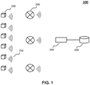
- the wireless system 100 can be a local network under the control of a local coordinator 400 to serve a certain control purpose or for data collection, and then the local coordinator may be further connected to a local application server 500.
- the system may be connected to the cloud, a backbone network, or a remote server 500 via a local coordinator, a gateway, a bridge, or a router device 400.
- a node 200 may be comprised in a lighting device, a luminaire, a sensor, or a switch to serve for the communication function of the lighting device, the luminaire, the sensor, or the switch.
- a node 200 may also be comprised in a HVAC system, a smart refrigerator, a smart oven, other smart white goods, or another sensor or actuator, or a remote controller in a broader building/home automation context.
- An asset may be a person or an object, such as a computer, a medical device, a package, etc.
- An asset may have or comprise a tag device 300.
- a tag device 300 may each be attached to a respective one of the assets.
- Each tag device 300 may include a transmitter to transmit wireless signals 350 such as beacon signals that include identification (ID) information of the asset and/or of the tag device.
- the tag devices 300 may transmit beacon signals, which may be compliant to a wireless standard, such as a BLE standard. Accordingly, some of the nodes 200 in the wireless system may be configured to operate also as asset sensor nodes for receiving such beacons from the tag devices 300.
- FIG. 2 schematically depicts basic components of a node 200 for communication in a wireless system 100.
- the node 200 comprises a radio unit 210, which is capable to operate multiple communication modes comprising at least a first communication mode capable to support a mesh or tree network with multi-hop routing, and a second communication mode capable to support a point-to-point connection.
- the radio unit 210 may comprise a single transceiver, which is a combo device to support at least both the first and the second communication modes and operate on a time-sharing basis according to one of the multiple communication modes each time.
- the radio unit 210 may comprise at least two separate transceivers 220, 230.
- the at least two separate transceivers 220, 230 may be single mode transceivers, and each supports one communication protocol. It is also possible that out of the at least two separate transceivers 220, 230 one is a combo device and the other is a single mode device.
- the node 200 further comprises a controller 240, which is configured to determine a main communication mode out of multiple communication modes according to a role assigned to the node.
- the node 200 may further comprise an application controller and/or an actuator, as indicated by 250 in FIG. 2 .
- the application controller or the actuator may be related to the control functionality of the node in a lighting context, a broader building automation context, an asset tracking context, or another application.
- the application controller and/or an actuator may execute the control commands received by the node. And the status information is provided by the application controller and/or the actuator as a feedback to the control system.
- the node 200 may further comprise a sensor, as indicated by 260 in FIG. 2 .
- the sensor 260 may be configured to detect presence and/or environmental information, such as temperature, humidity, etc.
- the sensing data may be collected in addition to or independent from the status information of the node, or the application controller and/or the actuator.
- the disclosed invention may be implemented in several different scenarios, depending on the applications to be enabled by the wireless system 100, the communication interface of the node 200, such as which are the multiple communication modes supported by the node.
- the different scenarios are explained by taking Zigbee as one example for the first communication protocol and BLE as one example for the second communication protocol.
- FIG. 3 demonstrates an exemplary network architecture with combo nodes according to various embodiments.
- the bright nodes are configured to be router nodes operating mainly in the first communication mode with the routing capability enabled.
- the dark nodes are configured to be asset tracking sensor nodes operating mainly in the second communication mode for receiving sensing data or for a point-to-point connection.
- a router node 200 is operable to distribute a control command to the plurality of nodes 200 and to forward status information from the plurality of nodes 200, via multi-hop routing.
- router nodes build up a sparse multi-hop network according to the first communication technology, which act as a kind of core network of the wireless system 100.
- Around each router node 200 with one-hop direct link there may be quite a few non-router nodes located.
- the non-router node can receive it directly from at least one router node in the vicinity.
- the non-router node may also be configured to operate mainly according to the second communication protocol, such as to support a second application in addition to the main application carried out by the wireless network.
- the router node in order to deliver a message to such a non-router node, it may happen that the router node will take extra effort to switch to an operation according to the second communication protocol in an on-demand manner, or the non-router node needs to rotate between the two operation modes regularly to be able to obtain messages from the wireless network.
- the first wireless communication protocol is mainly to implement large scale information distribution and collection in a wireless control system with a plurality of nodes, whereas the control system can be used for lighting control and/or building automation. It is important that the first wireless communication protocol supports multi-hop routing, which can be Zigbee, Thread, Bluetooth Mesh, Wi-Fi mesh, WirelessHART, SmartRF, CityTouch, IP500, Z-wave, or any other mesh or tree-based technology.
- the second communication protocol is in accordance with a Bluetooth low energy, BLE, standard. It can also be Wi-Fi direct, Zigbee Inter-PAN, Zigbee Touchlink, or another wireless communication standard that favours an easy setup for point-to-point connection.
- BLE Bluetooth low energy
- the two communication systems according to the first and the second communication protocols may use different modulation schemes, different frequency plans and time scheduling, one potential benefit that the local star network around each router node operating according to the second communication protocol is that mutual interference may be reduced significantly as compared to a homogeneous network.
- combo radio chips such as Zigbee/BLE and BLE/Wi-Fi chips, where there are two wireless protocol stacks sharing one radio front-end in the time domain.
- the new features include direct control of wireless lighting via BLE connections from a mobile, positioning of mobile phones via BLE signals sent from wireless lighting systems, and asset tracking via mobile BLE tags.
- combo radio chips While there are clear benefits of combo radio chips in lighting systems, there is also one common constraint that system designs must deal with: it is necessary to properly balance between the performance of classic lighting control and the performance of added new features.
- the common constraint stems from the fact that, while there are two radio protocol stacks, there is only one radio front-end that must be shared between the two radio protocol stacks - e.g. a Zigbee/BLE combo will be "blind” on BLE while active (transmitting, receiving or idle listening) on Zigbee, and vice versa. This would lead to significant performance degradation for at least one radio protocol if not managed well.
- This invention proposes an operation method in lighting IoT or other wireless networks that use combo radio chips to achieve reliably more than one function.
- An example is a lighting IoT network where every node has one combo radio chip that needs to perform both classic lighting control or data collection function (via Zigbee or Wi-Fi) and asset tracking function (using BLE).
- the system may also be constructed by nodes each comprising multiple single radio chips. And then it is not critical to schedule the multiple communication modes on a time-sharing basis. However, considering the same frequency bands are shared by the different short-range wireless communication technologies and energy efficiency, it may still be quite beneficial to avoid the scenario that more than one communication mode is enabled at the same time by the node.
- tag devices 300 send BLE beacons periodically which are being received by the nodes 200 using their combo radio chips in a lighting network 100. Measurement data of the BLE beacons are gathered and results are being sent through the lighting network 100 using the Zigbee protocol.
- the non-router nodes will be configured mainly in the BLE mode but will be in the Zigbee mode when it has something to send or to receive in Zigbee mode, e.g. to/from/via the router nodes.
- the reason why non-router nodes operate mainly in the BLE mode is to facilitate the reception of BLE beacon signals from tag devices.
- FIG. 3 An illustration of such a network configuration is shown in FIG. 3 , where the bright nodes are router nodes for lighting control application, and the dark nodes are non-router nodes and mainly used for asset tracking. If there are enough Zigbee router nodes nearby non-router nodes have no problem to send information via the lighting control network. However, non-router nodes may have problems to receive Zigbee messages if they operate mainly in the BLE mode and therefore it is likely to miss the majority of Zigbee packets.
- One option is to use the "end-device" role in Zigbee where bright nodes are the parents of end devices or the dark nodes.
- a parent will store messages for a child node, and the child node needs to poll periodically whether the parent has any message for it.
- the polling has a disadvantage that messages sent to the non-router node arrive with a latency.
- the latency is on average about half the polling period, with a maximum of one polling period.
- To reduce the latency by implementing a (more) frequent polling by the end device is not desirable, because that will compromise asset tracking performance consequently. Therefore, the inventors recognize it is advantageous to reduce the latency by sending a notification from the parent to the end-device that there is something for them to pick up via the other communication mode, which is the Zigbee mode in this example.
- the "end-device" mechanism according to the Zigbee standard is not used, a router node that needs to send a message to a non-router node would first switch to BLE and send a notification message to the non-router node.
- the notification message may be a short message that contains no or only partial application content.
- the router node then switches back to the Zigbee mode and only then (i.e. after the time that takes the non-router to also switch to Zigbee) sends the message over Zigbee to the non-router node.
- the non-router upon the reception of the notification message in the BLE mode, switches to Zigbee mode to receive the actual application message and then goes directly back to the BLE mode, such that the main assignment on asset tracking is not affected too much for the non-router node.
- the actual application message is typically longer and contains full application content in the case that the notification message contains no application content; or it contains partial application content that together with the partial application content conveyed in the notification message represents the full application content.
- the Zigbee communications may be completely secured since every node is part of the same Zigbee network after they join the network and the standard Zigbee security will be applied, or even additional application-level security.
- the advertisements are not typically secured by the BLE standard specifications.
- Some of the application data from the Zigbee network with more strict security requirements may not be suitable to send directly via BLE advertisement messages.
- the transmission of notifications instead of the actual application data there is much less security concern for protection of the notifications, or it is much more straightforward or simpler to implement proper security mechanisms.
- an application layer security mechanism may be applied to BLE advertisement data payload if security is needed. And distribution of security keys for BLE advertisements can be done via the (already secured) Zigbee networks.
- Zigbee router nodes that operate only or mostly in the Zigbee mode while dark nodes are Zigbee non-router nodes that operate mainly in the BLE mode for asset tracking.
- Zigbee router nodes need to be in the Zigbee mode most of the time for constantly listening on Zigbee networks to maintain proper operations.
- non-router nodes need to stay mostly in the BLE mode to listen to BLE signals from tag devices. Therefore, the best way to send any packets from the control network, or the Zigbee network, to the non-router nodes is in the mode in which they operate the most, the BLE mode.
- a bright node needs to send a broadcast message to all the nodes or many of the nodes in the network.
- This is typically a lighting control message triggered by a sensor or a switch that is co-located with the bright node but can also come from other sources such as a scheduler, a central controller, or another controller in the network.
- All the intended nodes in the network need to receive it within a short time so that all the intended lights behave in a synchronized manner in front of the user.
- the broadcast message is sent first in the Zigbee mode such that all bright nodes will be able to receive according to the Zigbee broadcast protocol.
- the bright nodes will also send notifications in the form of short BLE beacons or advertisements to reach dark nodes (non-router nodes) reliably since dark nodes are in the BLE mode most of the time.
- the notifications are simply to inform the intended dark nodes in the surrounding to switch to and listen on the Zigbee mode.
- the Zigbee broadcasting may be repeated several times, such as 3 - 4 times, by the bright Zigbee router nodes with a certain interval, such as 0.5 second. Each time the re-broadcasting by the neighbouring router nodes lasts about 100 ms.
- the benefits of the disclosed method includes reduced latency (much less than polling cycle and almost synchronous with the reception by the router nodes) and reduced workload (no fixed polling cycle scheduled).
- the dark nodes may also switch back and forth quickly between BLE mode and Zigbee mode in the aforementioned duration, such that the dark nodes may also spend some time in BLE mode without impairing the chance it receives Zigbee broadcasts.
- the notifications uniquely identifies the Zigbee broadcast message, so that a dark node can switch back to BLE once it has successfully received one instance of the Zigbee broadcast message and does not have to wait for repeats of the same message. This greatly improves the listening time on BLE. Otherwise the whole asset tracking network might be "deaf" or "blind” during the Zigbee broadcast cycle for around 1-1.5 second.
- a combination of a source address and a sequence number could be used.
- a combination of a source address, a destination address, and a sequence number could also be used.
- the system may be further improved by aligning the sending of notifications and Zigbee (re-)broadcasting in a bright node.
- notifications to the dark nodes are sent just before Zigbee (re-)broadcasting so that nearby dark nodes would have already been informed and have prepared in advance by switching to the Zigbee mode for receiving the incoming Zigbee (re-)broadcasts. This would require a timely coordination of the two modes with a node.
- a further refinement is that an expected time latency for starting Zigbee (re- )broadcasts after sending a notification message is also included in the notification such that a dark node can prepare better its schedule to receive Zigbee broadcasts according to the estimated latency.
- the dark node can use the time characteristics of Zigbee broadcasts.
- Zigbee rebroadcasts last about 100 ms and are spaced by 0.5 second
- a dark node may choose to only listen to Zigbee after the expected latency for 100 ms and switch back to its main communication mode (BLE) until 0.5 second later to switch to Zigbee again for 100 ms.
- BLE main communication mode
- dark nodes may spend very limited time on Zigbee without missing Zigbee broadcasts. Since such timing-related parameters may depend on the node firmware and/or size of the network, a node might be configured (by commissioner, central controller and/or router node) to use certain timing values, or to learn optimal values by observing the pattern.
- This scheme can be used in combination with other embodiments/examples, such as the combination with the scheme of stop listening on Zigbee once the dark node has received an intended Zigbee broadcast message successfully.
- non-routing dark nodes are Zigbee end devices, which are listening on the BLE channel as a default mode.
- the notification messages are sent by the router nodes as BLE advertisements to the non-routing dark nodes.
- the non-routing dark nodes Upon reception, the non-routing dark nodes will switch to the Zigbee mode, and check (as end-device) with their parent nodes according to the Zigbee protocol for receiving Zigbee (broadcast) data that is buffered by their parents. In this way, the initiative is completely on the dark nodes to receive some data.
- the switching to Zigbee can be optimized by supplying the Zigbee address of the intended receiver in the BLE notification message.
- the intended receiver switches to Zigbee whereas the others can stay on BLE to listen for beacon signals from tag devices.
- FIG. 4 shows a flow diagram of a communication method 600 of a node 200 in a wireless system.
- a main communication mode is determined out of multiple communication modes according to a role assigned to the node, and the multiple communication modes comprise a first communication mode capable to support a mesh or tree topology with multi-hop routing, according to a first communication technology, and a second communication mode capable to support a star topology with a point-to-point connection, according to a second communication technology.
- the method further comprises step S602 that the node operates mainly in the main communication mode; and in step S603, an instruction is generated according to a property of a packet that is either recently received in the main communication mode or recently generated by the node itself; and upon the instruction generated, the node switches, in step S604, temporarily to the other communication mode out of the multiple communication modes for sending or receiving using the other communication mode. And then in step S605, the node switches back to the main communication mode.
- Executable code for a method according to the invention may be stored on computer/machine readable storage means.
- Examples of computer/machine readable storage means include non-volatile memory devices, optical storage medium/devices, solid-state media, integrated circuits, servers, etc.
- the computer program product comprises non-transitory program code means stored on a computer readable medium for performing a method according to the invention when said program product is executed on a computer or a processing means comprised in a node or a network or a commissioning device as disclosed in the above-described embodiments.
- controller is used herein generally to describe various apparatus relating to, among other functions, the operation of one or more network devices or coordinators.
- a controller can be implemented in numerous ways (e.g., such as with dedicated hardware) to perform various functions discussed herein.
- a "processor” is one example of a controller which employs one or more microprocessors that may be programmed using software (e.g., microcode) to perform various functions discussed herein.
- a controller may be implemented with or without employing a processor and may also be implemented as a combination of dedicated hardware to perform some functions and a processor (e.g., one or more programmed microprocessors and associated circuitry) to perform other functions. Examples of controller components that may be employed in various embodiments of the present disclosure include, but are not limited to, conventional microprocessors, application specific integrated circuits (ASICs), and field-programmable gate arrays (FPGAs).
- ASICs application specific integrated circuits
- FPGAs field-programmable gate arrays
- a processor or controller may be associated with one or more storage media (generically referred to herein as "memory,” e.g., volatile and non-volatile computer memory such as RAM, PROM, EPROM, and EEPROM, compact disks, optical disks, etc.).
- the storage media may be encoded with one or more programs that, when executed on one or more processors and/or controllers, perform at least some of the functions discussed herein.
- Various storage media may be fixed within a processor or controller or may be transportable, such that the one or more programs stored thereon can be loaded into a processor or controller so as to implement various aspects of the present invention discussed herein.
- program or “computer program” are used herein in a generic sense to refer to any type of computer code (e.g., software or microcode) that can be employed to program one or more processors or controllers.
- network refers to any interconnection of two or more devices (including controllers or processors) that facilitates the transport of information (e.g. for device control, data storage, data exchange, etc.) between any two or more devices and/or among multiple devices coupled to the network.
- devices including controllers or processors
- information e.g. for device control, data storage, data exchange, etc.
- the phrase "at least one,” in reference to a list of one or more elements, should be understood to mean at least one element selected from any one or more of the elements in the list of elements, but not necessarily including at least one of each and every element specifically listed within the list of elements and not excluding any combinations of elements in the list of elements.
- This definition also allows that elements may optionally be present other than the elements specifically identified within the list of elements to which the phrase "at least one" refers, whether related or unrelated to those elements specifically identified
Landscapes
- Engineering & Computer Science (AREA)
- Computer Networks & Wireless Communication (AREA)
- Signal Processing (AREA)
- Mobile Radio Communication Systems (AREA)
Claims (10)
- Knoten (200) für eine Kommunikation für ein drahtloses System (100), der Knoten (200) umfassend:- eine Steuerung (240), die konfiguriert ist, um einen Standardkommunikationsmodus aus mehreren Kommunikationsmodi gemäß einer dem Knoten zugewiesenen Rolle zu bestimmen, wobei sich die Rolle auf eine durch den Knoten durchzuführende Aktivität bezieht und die mehreren Kommunikationsmodi umfassen• einen ersten Kommunikationsmodus, der in der Lage ist, eine Maschen- oder Baumtopologie mit Multi-Hop-Routing, gemäß einer ersten Kommunikationstechnologie, zu unterstützen, und• einen zweiten Kommunikationsmodus, der in der Lage ist, eine Sterntopologie mit einer Punkt-zu-Punkt-Verbindung, gemäß einer zweiten Kommunikationstechnologie, zu unterstützen;- eine Funkeinheit (210), die konfiguriert ist, um in dem ersten Kommunikationsmodus als der Standardkommunikationsmodus in Betrieb zu sein und, auf eine Anweisung von der Steuerung, in den zweiten Kommunikationsmodus zu wechseln und in dem zweiten Kommunikationsmodus eine Benachrichtigungsnachricht zu senden und dann in den ersten Kommunikationsmodus zurückzuwechseln;wobei die Steuerung (240) ferner konfiguriert ist, um die Anweisung, von dem ersten Kommunikationsmodus in den zweiten Kommunikationsmodus zu wechseln, gemäß einer Sicherheitsstufe eines durch die Funkeinheit in dem ersten Kommunikationsmodus empfangenen oder durch den Knoten selbst generierten Daten- oder Steuerpakets zu generieren.
- Knoten (200) nach Anspruch 1, wobei die Benachrichtigungsnachricht Planungsinformationen bezüglich eines Wechselns in den ersten Kommunikationsmodus für einen anderen Knoten angibt, der gegenwärtig in dem zweiten Kommunikationsmodus in Betrieb ist, bei denen es sich mindestens um eines handeln kann von:- einer Verzögerung, nach der, anschließend an den Empfang der Benachrichtigungsnachricht, eine Funkeinheit (210) des anderen Knotens in den ersten Kommunikationsmodus wechseln soll, und- eine Zeitdauer, die der andere Knoten (200) in dem ersten Kommunikationsmodus bleiben soll.
- Knoten (200) nach Anspruch 1 oder 2, wobei die Benachrichtigungsnachricht Unicast- oder Multicast-Adressinformationen hinsichtlich eines oder mehrerer beabsichtigter Zielknoten der Benachrichtigungsnachricht umfasst.
- Knoten (200) nach einem der vorstehenden Ansprüche, wobei die Rolle dem Knoten (200) gemäß mindestens einem zugewiesen werden kann: einer Position des Knotens, einer zuvor bestimmten Systemkonfiguration, einer kontextabhängigen Laufzeitknotenkonfiguration, einem Anwendungsbereitstellungsschema des drahtlosen Systems.
- Knoten (200) nach einem der vorstehenden Ansprüche 1 bis 4, wobei die dem Knoten (200) zugewiesene Rolle die eines Routerknotens zum Ermöglichen der Kommunikation zwischen Knoten in dem drahtlosen System ist.
- Knoten (200) nach Anspruch 5, wobei die Steuerung (240) ferner konfiguriert ist, um den ersten Kommunikationsmodus dazu zu bestimmen, der Standardkommunikationsmodus zu sein, und die Funkeinheit (210) ferner konfiguriert ist, um für einen Großteil ihres Arbeitszyklus in dem ersten Kommunikationsmodus in Betrieb zu sein, um die Kommunikation zwischen Knoten in dem drahtlosen System (100) mit Multi-Hop-Routing zu unterstützen.
- Drahtloses System (100) umfassend eine Vielzahl von Knoten (200) wie in Anspruch 1 beansprucht.
- Drahtloses System (100) nach Anspruch 7, wobei das drahtlose System (100) ein drahtloses Lichtsteuersystem ist.
- Kommunikationsverfahren (600) eines Knotens (200) in einem drahtlosen System (100), wobei das Verfahren (600) umfasst, dass der Knoten (200):- einen Standardkommunikationsmodus aus mehreren Kommunikationsmodi gemäß einer dem Knoten (200) zugewiesenen Rolle bestimmt (S601), wobei sich die Rolle auf eine durch den Knoten durchzuführende Aktivität bezieht und die mehreren Kommunikationsmodi umfassen• einen ersten Kommunikationsmodus, der in der Lage ist, eine Maschen- oder Baumtopologie mit Multi-Hop-Routing, gemäß einer ersten Kommunikationstechnologie, zu unterstützen, und• einen zweiten Kommunikationsmodus, der in der Lage ist, eine Sterntopologie mit einer Punkt-zu-Punkt-Verbindung, gemäß einer zweiten Kommunikationstechnologie, zu unterstützen;- in dem ersten Kommunikationsmodus als der Standardkommunikationsmodus in Betrieb ist (S602) und, auf eine Anweisung, in den zweiten Kommunikationsmodus wechselt und eine Benachrichtigungsnachricht in dem zweiten Kommunikationsmodus sendet und dann in den ersten Kommunikationsmodus zurückwechselt;- die Anweisung, von dem ersten Kommunikationsmodus in den zweiten Kommunikationsmodus zu wechseln, gemäß einer Sicherheitsstufe eines in dem ersten Kommunikationsmodus empfangenen Daten- oder Steuerpakets generiert (S603).
- Rechenprogramm, umfassend Codemittel, die, wenn das Programm durch einen Knoten (200), umfassend Verarbeitungsmittel, ausgeführt wird, veranlassen, dass die Verarbeitungsmittel das Verfahren nach Anspruch 9 vornehmen.
Applications Claiming Priority (2)
| Application Number | Priority Date | Filing Date | Title |
|---|---|---|---|
| EP20177738 | 2020-06-02 | ||
| PCT/EP2021/064534 WO2021245019A1 (en) | 2020-06-02 | 2021-05-31 | Reliable and security-aware communication in a hybrid wireless network |
Publications (2)
| Publication Number | Publication Date |
|---|---|
| EP4158879A1 EP4158879A1 (de) | 2023-04-05 |
| EP4158879B1 true EP4158879B1 (de) | 2025-03-05 |
Family
ID=70975742
Family Applications (1)
| Application Number | Title | Priority Date | Filing Date |
|---|---|---|---|
| EP21728086.6A Active EP4158879B1 (de) | 2020-06-02 | 2021-05-31 | Zuverlässige und sicherheitsbewusste kommunikation in einem hybriden drahtlosen netzwerk |
Country Status (5)
| Country | Link |
|---|---|
| US (1) | US12414027B2 (de) |
| EP (1) | EP4158879B1 (de) |
| JP (1) | JP7671787B2 (de) |
| CN (1) | CN115669012A (de) |
| WO (1) | WO2021245019A1 (de) |
Family Cites Families (20)
| Publication number | Priority date | Publication date | Assignee | Title |
|---|---|---|---|---|
| US6901241B2 (en) * | 1998-02-11 | 2005-05-31 | Telefonaktiebolaget L M Ericsson (Publ) | System, method and apparatus for secure transmission of confidential information |
| US7821449B2 (en) * | 2005-01-12 | 2010-10-26 | Qualcomm Incorporated | Base station almanac assisted positioning |
| CN101471704B (zh) | 2007-12-26 | 2013-03-20 | 陈澎 | 一种双模设备及网络管理方法 |
| WO2013030779A1 (en) * | 2011-09-02 | 2013-03-07 | Koninklijke Philips Electronics N.V. | Device and method for controlling a node of a wireless network |
| CN107079029B (zh) * | 2014-11-07 | 2020-12-11 | 飞利浦灯具控股公司 | 网络系统及其相应的方法和计算机可读存储介质 |
| CN105657639B (zh) | 2015-12-25 | 2019-06-28 | 泰凌微电子(上海)有限公司 | 双模设备及其实现同时通信的方法 |
| US9894512B2 (en) | 2016-04-27 | 2018-02-13 | Texas Instruments Incorporated | Mode-speed switching for exploiting high-speed in BLE-Mesh systems |
| EP3255931B1 (de) | 2016-06-07 | 2019-08-07 | Nxp B.V. | Konfiguration von drahtloser kommunikation und werbeereignis gemäss mehreren kommunikationsprotokollen |
| EP3255949A1 (de) | 2016-06-07 | 2017-12-13 | Nxp B.V. | Konfiguration von drahtlosen kommunikation nach mehreren kommunikationsprotokollen |
| US10129853B2 (en) | 2016-06-08 | 2018-11-13 | Cognitive Systems Corp. | Operating a motion detection channel in a wireless communication network |
| US10210356B2 (en) * | 2016-07-21 | 2019-02-19 | Nippon Sysits Co. Ltd. | Multi signal diffusion integrated system and method |
| CN106549966B (zh) * | 2016-10-31 | 2020-09-04 | 美的智慧家居科技有限公司 | 通信安全等级切换的方法、系统、家电设备和移动终端 |
| WO2018228883A1 (en) | 2017-06-12 | 2018-12-20 | Philips Lighting Holding B.V. | System and method for relaying single-hop traffic over wireless multi-hop networks |
| CN107249173B (zh) * | 2017-06-21 | 2019-09-17 | 深圳市盛路物联通讯技术有限公司 | 一种物联网通信模式的切换控制方法及系统 |
| CN111052687B (zh) | 2017-09-06 | 2022-07-12 | 昕诺飞控股有限公司 | 用于控制向多跳网络添加网络节点的装置和方法 |
| EP3763165A1 (de) * | 2018-03-05 | 2021-01-13 | Signify Holding B.V. | Bakenbasierte übergabeoption zur inbetriebnahme und steuerung von drahtlosnetzwerkvorrichtungen |
| EP3844909B1 (de) * | 2018-08-27 | 2025-04-02 | Signify Holding B.V. | Bestimmung der eignung von netzwerkknoten für die hf-basierte präsenz- und/oder ortserkennung |
| CN113396558B (zh) | 2019-02-15 | 2024-07-09 | 昕诺飞控股有限公司 | 对基于rf的存在检测和/或定位以及消息接收的时变分配 |
| EP3939370B1 (de) | 2019-03-14 | 2023-11-15 | Signify Holding B.V. | Empfänger-zentrierte kommunikation durch kombinierte netzwerktechnologien zur erhöhung der zuverlässigkeit |
| US11324075B2 (en) * | 2019-12-19 | 2022-05-03 | Itron, Inc. | Techniques for multi-data rate communications |
-
2021
- 2021-05-31 US US17/926,288 patent/US12414027B2/en active Active
- 2021-05-31 WO PCT/EP2021/064534 patent/WO2021245019A1/en not_active Ceased
- 2021-05-31 CN CN202180039929.3A patent/CN115669012A/zh active Pending
- 2021-05-31 EP EP21728086.6A patent/EP4158879B1/de active Active
- 2021-05-31 JP JP2022574276A patent/JP7671787B2/ja active Active
Also Published As
| Publication number | Publication date |
|---|---|
| US12414027B2 (en) | 2025-09-09 |
| CN115669012A (zh) | 2023-01-31 |
| JP2023528426A (ja) | 2023-07-04 |
| EP4158879A1 (de) | 2023-04-05 |
| WO2021245019A1 (en) | 2021-12-09 |
| US20230217344A1 (en) | 2023-07-06 |
| JP7671787B2 (ja) | 2025-05-02 |
Similar Documents
| Publication | Publication Date | Title |
|---|---|---|
| US10785672B2 (en) | Dynamic wireless network topology for reduced spectrum flooding | |
| CA3024227C (en) | Heuristic optimization of performance of a radio frequency nodal network | |
| US20180212826A1 (en) | Centralized controlling system controlling interactions and cooperation between radio-operated devices operating in a mesh network supporting multiple radio communication protocols | |
| EP2396952B1 (de) | Verfahren zur kommunikation in einem netzwerk mit batterielosem zigbee-gerät, netzwerk und vorrichtung dafür | |
| JP5770199B2 (ja) | バッテリレスジグビー装置を有するネットワークにおいて通信する方法、それに対するネットワーク及び装置 | |
| US10637684B2 (en) | Mesh network connectivity | |
| TWI499327B (zh) | 於包含無電池群蜂裝置之網路中通信的方法及其網路與裝置 | |
| EP4147490B1 (de) | Effiziente inbetriebnahme eines drahtlosen steuerungssystems | |
| US10736177B2 (en) | Dynamic wireless network topology for reduced spectrum flooding | |
| US12317393B2 (en) | Proximity-based commissioning system | |
| US11751030B2 (en) | Trigger-based commissioning system | |
| EP4158879B1 (de) | Zuverlässige und sicherheitsbewusste kommunikation in einem hybriden drahtlosen netzwerk | |
| EP4091365B1 (de) | Drahtloses steuersystem auf der basis eines hybridnetzwerks | |
| US20210243079A1 (en) | Bi-directional commissioning for low-power wireless network devices |
Legal Events
| Date | Code | Title | Description |
|---|---|---|---|
| STAA | Information on the status of an ep patent application or granted ep patent |
Free format text: STATUS: UNKNOWN |
|
| STAA | Information on the status of an ep patent application or granted ep patent |
Free format text: STATUS: THE INTERNATIONAL PUBLICATION HAS BEEN MADE |
|
| PUAI | Public reference made under article 153(3) epc to a published international application that has entered the european phase |
Free format text: ORIGINAL CODE: 0009012 |
|
| STAA | Information on the status of an ep patent application or granted ep patent |
Free format text: STATUS: REQUEST FOR EXAMINATION WAS MADE |
|
| 17P | Request for examination filed |
Effective date: 20230102 |
|
| AK | Designated contracting states |
Kind code of ref document: A1 Designated state(s): AL AT BE BG CH CY CZ DE DK EE ES FI FR GB GR HR HU IE IS IT LI LT LU LV MC MK MT NL NO PL PT RO RS SE SI SK SM TR |
|
| DAV | Request for validation of the european patent (deleted) | ||
| DAX | Request for extension of the european patent (deleted) | ||
| REG | Reference to a national code |
Ref country code: DE Ref legal event code: R079 Free format text: PREVIOUS MAIN CLASS: H04L0029080000 Ipc: H04W0012000000 Ref country code: DE Ref legal event code: R079 Ref document number: 602021027153 Country of ref document: DE Free format text: PREVIOUS MAIN CLASS: H04L0029080000 Ipc: H04W0012000000 |
|
| GRAP | Despatch of communication of intention to grant a patent |
Free format text: ORIGINAL CODE: EPIDOSNIGR1 |
|
| STAA | Information on the status of an ep patent application or granted ep patent |
Free format text: STATUS: GRANT OF PATENT IS INTENDED |
|
| RIC1 | Information provided on ipc code assigned before grant |
Ipc: H04W 88/06 20090101ALI20240829BHEP Ipc: H04W 84/18 20090101ALI20240829BHEP Ipc: H04W 40/22 20090101ALI20240829BHEP Ipc: H04W 4/02 20180101ALI20240829BHEP Ipc: H04W 4/80 20180101ALI20240829BHEP Ipc: H04W 12/00 20210101AFI20240829BHEP |
|
| INTG | Intention to grant announced |
Effective date: 20240925 |
|
| P01 | Opt-out of the competence of the unified patent court (upc) registered |
Free format text: CASE NUMBER: APP_61233/2024 Effective date: 20241114 |
|
| GRAS | Grant fee paid |
Free format text: ORIGINAL CODE: EPIDOSNIGR3 |
|
| GRAA | (expected) grant |
Free format text: ORIGINAL CODE: 0009210 |
|
| STAA | Information on the status of an ep patent application or granted ep patent |
Free format text: STATUS: THE PATENT HAS BEEN GRANTED |
|
| AK | Designated contracting states |
Kind code of ref document: B1 Designated state(s): AL AT BE BG CH CY CZ DE DK EE ES FI FR GB GR HR HU IE IS IT LI LT LU LV MC MK MT NL NO PL PT RO RS SE SI SK SM TR |
|
| REG | Reference to a national code |
Ref country code: GB Ref legal event code: FG4D |
|
| REG | Reference to a national code |
Ref country code: CH Ref legal event code: EP |
|
| REG | Reference to a national code |
Ref country code: IE Ref legal event code: FG4D |
|
| REG | Reference to a national code |
Ref country code: DE Ref legal event code: R096 Ref document number: 602021027153 Country of ref document: DE |
|
| PG25 | Lapsed in a contracting state [announced via postgrant information from national office to epo] |
Ref country code: RS Free format text: LAPSE BECAUSE OF FAILURE TO SUBMIT A TRANSLATION OF THE DESCRIPTION OR TO PAY THE FEE WITHIN THE PRESCRIBED TIME-LIMIT Effective date: 20250605 |
|
| PG25 | Lapsed in a contracting state [announced via postgrant information from national office to epo] |
Ref country code: FI Free format text: LAPSE BECAUSE OF FAILURE TO SUBMIT A TRANSLATION OF THE DESCRIPTION OR TO PAY THE FEE WITHIN THE PRESCRIBED TIME-LIMIT Effective date: 20250305 |
|
| REG | Reference to a national code |
Ref country code: NL Ref legal event code: MP Effective date: 20250305 |
|
| PG25 | Lapsed in a contracting state [announced via postgrant information from national office to epo] |
Ref country code: ES Free format text: LAPSE BECAUSE OF FAILURE TO SUBMIT A TRANSLATION OF THE DESCRIPTION OR TO PAY THE FEE WITHIN THE PRESCRIBED TIME-LIMIT Effective date: 20250305 |
|
| PGFP | Annual fee paid to national office [announced via postgrant information from national office to epo] |
Ref country code: GB Payment date: 20250520 Year of fee payment: 5 |
|
| REG | Reference to a national code |
Ref country code: LT Ref legal event code: MG9D |
|
| PG25 | Lapsed in a contracting state [announced via postgrant information from national office to epo] |
Ref country code: NO Free format text: LAPSE BECAUSE OF FAILURE TO SUBMIT A TRANSLATION OF THE DESCRIPTION OR TO PAY THE FEE WITHIN THE PRESCRIBED TIME-LIMIT Effective date: 20250605 |
|
| PG25 | Lapsed in a contracting state [announced via postgrant information from national office to epo] |
Ref country code: HR Free format text: LAPSE BECAUSE OF FAILURE TO SUBMIT A TRANSLATION OF THE DESCRIPTION OR TO PAY THE FEE WITHIN THE PRESCRIBED TIME-LIMIT Effective date: 20250305 |
|
| PG25 | Lapsed in a contracting state [announced via postgrant information from national office to epo] |
Ref country code: LV Free format text: LAPSE BECAUSE OF FAILURE TO SUBMIT A TRANSLATION OF THE DESCRIPTION OR TO PAY THE FEE WITHIN THE PRESCRIBED TIME-LIMIT Effective date: 20250305 |
|
| PGFP | Annual fee paid to national office [announced via postgrant information from national office to epo] |
Ref country code: FR Payment date: 20250526 Year of fee payment: 5 |
|
| PG25 | Lapsed in a contracting state [announced via postgrant information from national office to epo] |
Ref country code: BG Free format text: LAPSE BECAUSE OF FAILURE TO SUBMIT A TRANSLATION OF THE DESCRIPTION OR TO PAY THE FEE WITHIN THE PRESCRIBED TIME-LIMIT Effective date: 20250305 Ref country code: GR Free format text: LAPSE BECAUSE OF FAILURE TO SUBMIT A TRANSLATION OF THE DESCRIPTION OR TO PAY THE FEE WITHIN THE PRESCRIBED TIME-LIMIT Effective date: 20250606 |
|
| REG | Reference to a national code |
Ref country code: AT Ref legal event code: MK05 Ref document number: 1774081 Country of ref document: AT Kind code of ref document: T Effective date: 20250305 |
|
| PG25 | Lapsed in a contracting state [announced via postgrant information from national office to epo] |
Ref country code: NL Free format text: LAPSE BECAUSE OF FAILURE TO SUBMIT A TRANSLATION OF THE DESCRIPTION OR TO PAY THE FEE WITHIN THE PRESCRIBED TIME-LIMIT Effective date: 20250305 |
|
| PG25 | Lapsed in a contracting state [announced via postgrant information from national office to epo] |
Ref country code: SE Free format text: LAPSE BECAUSE OF FAILURE TO SUBMIT A TRANSLATION OF THE DESCRIPTION OR TO PAY THE FEE WITHIN THE PRESCRIBED TIME-LIMIT Effective date: 20250305 |
|
| PG25 | Lapsed in a contracting state [announced via postgrant information from national office to epo] |
Ref country code: SM Free format text: LAPSE BECAUSE OF FAILURE TO SUBMIT A TRANSLATION OF THE DESCRIPTION OR TO PAY THE FEE WITHIN THE PRESCRIBED TIME-LIMIT Effective date: 20250305 |
|
| PG25 | Lapsed in a contracting state [announced via postgrant information from national office to epo] |
Ref country code: PT Free format text: LAPSE BECAUSE OF FAILURE TO SUBMIT A TRANSLATION OF THE DESCRIPTION OR TO PAY THE FEE WITHIN THE PRESCRIBED TIME-LIMIT Effective date: 20250707 |
|
| PGFP | Annual fee paid to national office [announced via postgrant information from national office to epo] |
Ref country code: DE Payment date: 20250728 Year of fee payment: 5 |
|
| PG25 | Lapsed in a contracting state [announced via postgrant information from national office to epo] |
Ref country code: IT Free format text: LAPSE BECAUSE OF FAILURE TO SUBMIT A TRANSLATION OF THE DESCRIPTION OR TO PAY THE FEE WITHIN THE PRESCRIBED TIME-LIMIT Effective date: 20250305 Ref country code: PL Free format text: LAPSE BECAUSE OF FAILURE TO SUBMIT A TRANSLATION OF THE DESCRIPTION OR TO PAY THE FEE WITHIN THE PRESCRIBED TIME-LIMIT Effective date: 20250305 |
|
| PG25 | Lapsed in a contracting state [announced via postgrant information from national office to epo] |
Ref country code: AT Free format text: LAPSE BECAUSE OF FAILURE TO SUBMIT A TRANSLATION OF THE DESCRIPTION OR TO PAY THE FEE WITHIN THE PRESCRIBED TIME-LIMIT Effective date: 20250305 |
|
| PG25 | Lapsed in a contracting state [announced via postgrant information from national office to epo] |
Ref country code: CZ Free format text: LAPSE BECAUSE OF FAILURE TO SUBMIT A TRANSLATION OF THE DESCRIPTION OR TO PAY THE FEE WITHIN THE PRESCRIBED TIME-LIMIT Effective date: 20250305 Ref country code: EE Free format text: LAPSE BECAUSE OF FAILURE TO SUBMIT A TRANSLATION OF THE DESCRIPTION OR TO PAY THE FEE WITHIN THE PRESCRIBED TIME-LIMIT Effective date: 20250305 |
|
| PG25 | Lapsed in a contracting state [announced via postgrant information from national office to epo] |
Ref country code: RO Free format text: LAPSE BECAUSE OF FAILURE TO SUBMIT A TRANSLATION OF THE DESCRIPTION OR TO PAY THE FEE WITHIN THE PRESCRIBED TIME-LIMIT Effective date: 20250305 |
|
| PG25 | Lapsed in a contracting state [announced via postgrant information from national office to epo] |
Ref country code: SK Free format text: LAPSE BECAUSE OF FAILURE TO SUBMIT A TRANSLATION OF THE DESCRIPTION OR TO PAY THE FEE WITHIN THE PRESCRIBED TIME-LIMIT Effective date: 20250305 |
|
| PG25 | Lapsed in a contracting state [announced via postgrant information from national office to epo] |
Ref country code: IS Free format text: LAPSE BECAUSE OF FAILURE TO SUBMIT A TRANSLATION OF THE DESCRIPTION OR TO PAY THE FEE WITHIN THE PRESCRIBED TIME-LIMIT Effective date: 20250705 |
|
| REG | Reference to a national code |
Ref country code: DE Ref legal event code: R097 Ref document number: 602021027153 Country of ref document: DE |
|
| REG | Reference to a national code |
Ref country code: CH Ref legal event code: H13 Free format text: ST27 STATUS EVENT CODE: U-0-0-H10-H13 (AS PROVIDED BY THE NATIONAL OFFICE) Effective date: 20251223 |
|
| PLBE | No opposition filed within time limit |
Free format text: ORIGINAL CODE: 0009261 |
|
| STAA | Information on the status of an ep patent application or granted ep patent |
Free format text: STATUS: NO OPPOSITION FILED WITHIN TIME LIMIT |
|
| PG25 | Lapsed in a contracting state [announced via postgrant information from national office to epo] |
Ref country code: DK Free format text: LAPSE BECAUSE OF FAILURE TO SUBMIT A TRANSLATION OF THE DESCRIPTION OR TO PAY THE FEE WITHIN THE PRESCRIBED TIME-LIMIT Effective date: 20250305 |
|
| REG | Reference to a national code |
Ref country code: CH Ref legal event code: L10 Free format text: ST27 STATUS EVENT CODE: U-0-0-L10-L00 (AS PROVIDED BY THE NATIONAL OFFICE) Effective date: 20260114 |
|
| PG25 | Lapsed in a contracting state [announced via postgrant information from national office to epo] |
Ref country code: LU Free format text: LAPSE BECAUSE OF NON-PAYMENT OF DUE FEES Effective date: 20250531 |
|
| PG25 | Lapsed in a contracting state [announced via postgrant information from national office to epo] |
Ref country code: CH Free format text: LAPSE BECAUSE OF NON-PAYMENT OF DUE FEES Effective date: 20250531 |
|
| PG25 | Lapsed in a contracting state [announced via postgrant information from national office to epo] |
Ref country code: MC Free format text: LAPSE BECAUSE OF FAILURE TO SUBMIT A TRANSLATION OF THE DESCRIPTION OR TO PAY THE FEE WITHIN THE PRESCRIBED TIME-LIMIT Effective date: 20250305 |
|
| 26N | No opposition filed |
Effective date: 20251208 |