EP4157716B1 - Schub- und steuersystem für flugzeuge - Google Patents
Schub- und steuersystem für flugzeuge Download PDFInfo
- Publication number
- EP4157716B1 EP4157716B1 EP20754353.9A EP20754353A EP4157716B1 EP 4157716 B1 EP4157716 B1 EP 4157716B1 EP 20754353 A EP20754353 A EP 20754353A EP 4157716 B1 EP4157716 B1 EP 4157716B1
- Authority
- EP
- European Patent Office
- Prior art keywords
- propellers
- power unit
- propeller
- aircraft
- power units
- Prior art date
- Legal status (The legal status is an assumption and is not a legal conclusion. Google has not performed a legal analysis and makes no representation as to the accuracy of the status listed.)
- Active
Links
Images

Classifications
-
- B—PERFORMING OPERATIONS; TRANSPORTING
- B64—AIRCRAFT; AVIATION; COSMONAUTICS
- B64C—AEROPLANES; HELICOPTERS
- B64C29/00—Aircraft capable of landing or taking-off vertically, e.g. vertical take-off and landing [VTOL] aircraft
- B64C29/0008—Aircraft capable of landing or taking-off vertically, e.g. vertical take-off and landing [VTOL] aircraft having its flight directional axis horizontal when grounded
- B64C29/0016—Aircraft capable of landing or taking-off vertically, e.g. vertical take-off and landing [VTOL] aircraft having its flight directional axis horizontal when grounded the lift during taking-off being created by free or ducted propellers or by blowers
- B64C29/0025—Aircraft capable of landing or taking-off vertically, e.g. vertical take-off and landing [VTOL] aircraft having its flight directional axis horizontal when grounded the lift during taking-off being created by free or ducted propellers or by blowers the propellers being fixed relative to the fuselage
-
- B—PERFORMING OPERATIONS; TRANSPORTING
- B64—AIRCRAFT; AVIATION; COSMONAUTICS
- B64C—AEROPLANES; HELICOPTERS
- B64C11/00—Propellers, e.g. of ducted type; Features common to propellers and rotors for rotorcraft
- B64C11/46—Arrangements of, or constructional features peculiar to, multiple propellers
- B64C11/48—Units of two or more coaxial propellers
-
- B—PERFORMING OPERATIONS; TRANSPORTING
- B64—AIRCRAFT; AVIATION; COSMONAUTICS
- B64U—UNMANNED AERIAL VEHICLES [UAV]; EQUIPMENT THEREFOR
- B64U30/00—Means for producing lift; Empennages; Arrangements thereof
- B64U30/20—Rotors; Rotor supports
-
- B—PERFORMING OPERATIONS; TRANSPORTING
- B64—AIRCRAFT; AVIATION; COSMONAUTICS
- B64U—UNMANNED AERIAL VEHICLES [UAV]; EQUIPMENT THEREFOR
- B64U50/00—Propulsion; Power supply
- B64U50/10—Propulsion
- B64U50/13—Propulsion using external fans or propellers
-
- B—PERFORMING OPERATIONS; TRANSPORTING
- B64—AIRCRAFT; AVIATION; COSMONAUTICS
- B64U—UNMANNED AERIAL VEHICLES [UAV]; EQUIPMENT THEREFOR
- B64U50/00—Propulsion; Power supply
- B64U50/10—Propulsion
- B64U50/13—Propulsion using external fans or propellers
- B64U50/14—Propulsion using external fans or propellers ducted or shrouded
-
- B—PERFORMING OPERATIONS; TRANSPORTING
- B64—AIRCRAFT; AVIATION; COSMONAUTICS
- B64U—UNMANNED AERIAL VEHICLES [UAV]; EQUIPMENT THEREFOR
- B64U50/00—Propulsion; Power supply
- B64U50/10—Propulsion
- B64U50/18—Thrust vectoring
-
- B—PERFORMING OPERATIONS; TRANSPORTING
- B64—AIRCRAFT; AVIATION; COSMONAUTICS
- B64U—UNMANNED AERIAL VEHICLES [UAV]; EQUIPMENT THEREFOR
- B64U50/00—Propulsion; Power supply
- B64U50/10—Propulsion
- B64U50/19—Propulsion using electrically powered motors
-
- B—PERFORMING OPERATIONS; TRANSPORTING
- B64—AIRCRAFT; AVIATION; COSMONAUTICS
- B64C—AEROPLANES; HELICOPTERS
- B64C27/00—Rotorcraft; Rotors peculiar thereto
- B64C27/20—Rotorcraft characterised by having shrouded rotors, e.g. flying platforms
-
- B—PERFORMING OPERATIONS; TRANSPORTING
- B64—AIRCRAFT; AVIATION; COSMONAUTICS
- B64U—UNMANNED AERIAL VEHICLES [UAV]; EQUIPMENT THEREFOR
- B64U10/00—Type of UAV
- B64U10/10—Rotorcrafts
- B64U10/13—Flying platforms
-
- B—PERFORMING OPERATIONS; TRANSPORTING
- B64—AIRCRAFT; AVIATION; COSMONAUTICS
- B64U—UNMANNED AERIAL VEHICLES [UAV]; EQUIPMENT THEREFOR
- B64U10/00—Type of UAV
- B64U10/10—Rotorcrafts
- B64U10/13—Flying platforms
- B64U10/14—Flying platforms with four distinct rotor axes, e.g. quadcopters
-
- B—PERFORMING OPERATIONS; TRANSPORTING
- B64—AIRCRAFT; AVIATION; COSMONAUTICS
- B64U—UNMANNED AERIAL VEHICLES [UAV]; EQUIPMENT THEREFOR
- B64U30/00—Means for producing lift; Empennages; Arrangements thereof
- B64U30/20—Rotors; Rotor supports
- B64U30/26—Ducted or shrouded rotors
-
- B—PERFORMING OPERATIONS; TRANSPORTING
- B64—AIRCRAFT; AVIATION; COSMONAUTICS
- B64U—UNMANNED AERIAL VEHICLES [UAV]; EQUIPMENT THEREFOR
- B64U50/00—Propulsion; Power supply
- B64U50/10—Propulsion
- B64U50/11—Propulsion using internal combustion piston engines
Definitions
- the invention relates to electrically powered upward thrust aircraft, more particularly to unmanned aircrafts with main upward thrust propeller mechanism and additional directional control propeller mechanisms.
- Unmanned or manned aircrafts are rapidly gaining popularity not only in research or military fields but also in civilian applications.
- One of such aircrafts for transport of passengers or other cargo is a hybrid of a helicopter and a conventional flying drone with a central upward lifting thrust mechanism and auxiliary directional control propeller mechanisms.
- Such a system combines positive aerodynamic-energy characteristics of the helicopter's upward thrust and positive multi-propeller drone control principle when the control is performed by electrically differentiating (changing thrust) with the help of additional control thrust centers.
- Korean patent application Nr. KR20170018671A discloses a hybrid drone system comprising a drone fuselage having a duct structure; a rotor arranged in a central portion of the drone fuselage to generate lift and thrust; a turbo shaft engine generating rotation power to transmit the rotation power to the rotor; a generator generating electric energy by using the rotation power with the turbo shaft engine; and a plurality of propellers arranged in a duct structure formed by being spaced from an outer circumference of the drone fuselage, and rotated by being interconnected to an electric motor operated by the electric energy which is generated by the generator.
- Chinese patent application Nr. CN109941429A discloses an unmanned aerial vehicle comprising a cover shell, a thrust duct is arranged in the center of the cover shell, and steering ducts are circumferentially distributed on the front, back, left and right sides of the cover shell around the center of the cover shell, and the thrust duct is internally provided with a thrust rotor wing device and a thrust air guide assembly; the steering ducts are internally provided with horizontal rotor wing devices, and steering air guide assemblies are arranged in the steering ducts located on the front and back sides.
- DE102005046155A1 discloses a helicopter (1) having at least two main rotors (2,3) mounted coaxially with respect to each other on a main rotor axle and at least one drive device (4,5) that drives the main rotors to rotate in contrarotation. It also has at least three control drives (7,10,11) that are provided at a distance from the main rotor axle (15). Each control drive has a rotor and a drive device.
- WO2016/081041 A1 discloses a propulsion system for a ducted fan vertical takeoff and landing aircraft (VTOL) powered by multiple electric motors with two, counter rotating electric motors comprising the primary thrust generation within a ducted fan component and 3 or more external electric motors providing lift, stability and directional control of the aircraft.
- VTOL ducted fan vertical takeoff and landing aircraft
- US patent application Nr. US2018/029703A1 discloses an aerodyne including a supporting structure, to which are connected: at least one supporting axial blower, attached to the supporting structure; at least one main engine driving the supporting blower; at least three attitude blowers controlling roll and pitch, each attitude blower having an electrical motor and being attached, respectively, to one of the elongate arms that are distributed in a laterally, outwardly projecting manner around the supporting structure, to which each arm is connected by an inner end portion, the axis of rotation of each attitude blower being attached relative to the supporting structure, and all the attitude blowers being located outside the space centrally occupied by the supporting blower; at least one battery for supplying power to the electrical motors of the attitude blowers; a landing gear attached under the supporting structure; and a nacelle for holding the battery and a payload.
- US patent application Nr. US2016/304193A1 discloses a flying vehicle with a fuselage having a longitudinal axis, a cockpit extending substantially from the center of the fuselage, a left front wing extending from the fuselage, a right front wing extending from the fuselage, a left rear wing extending from the fuselage, a right rear wing extending from the fuselage.
- Each wing contains a rotor rotatably mounted and a direct drive brushless motor providing directional control of the vehicle.
- a centrally located ducted fan encompasses the cockpit and provides VTOL capabilities. The central location of the cockpit and central ducted fan aid in balance and stability.
- U.S. Patent Application No. US14/987,198 discloses a multi-rotor flying vehicle having a longitudinal fuselage, a passenger compartment, front wings and rear wings. Each wing has a propeller mounted on a brushless electric motor for control of direction of movement of the aircraft.
- the central power unit for generating main upward thrust force comprises an aerodynamic tubular body, a brushless electric motor and a propeller.
- the central power unit for lifting or lowering the aircraft may comprise one propeller or two propellers rotating in opposite directions.
- the power units in the wings have tilting ability to control the direction of movement of the aircraft.
- Main disadvantage of this system is the gyroscopic and stabilizing effects created in both central and peripheral power units, making aircraft's control and movement difficult in the horizontal direction.
- US 2017/274984 A1 describes aerial vehicles and systems for altering the noise generated by the rotation of a propeller during flight of the aerial vehicle.
- propellers of the aerial vehicle are paired in a coaxially aligned configuration in which the pair of propellers both rotate in the same direction, are rotationally phase aligned, and separated a defined distance so that the noise from high pressure pulse of the induced flow from the lower propeller is at least partially canceled out by the noise of the high pressure pulse of the induced flow from the upper propeller.
- the present invention solves the drawbacks known in the art and provides additional advantages: it improves energy parameters of unmanned and manned aircrafts such as ratio of aerodynamic thrust and energy consumption of propellers, i.e. higher lifting power is generated with less energy consumption.
- the presently claimed invention discloses an aircraft thrust and control system according to appended claim 1.
- the presently claimed invention discloses also an aircraft comprising the inventive aircraft thrust and control system, according to appended claim 7.
- “Aerodynamic operating zone” areas at the top, bottom and sides of a propeller where the rotation of the propeller results in a gradient of the velocity of the airflow between the generated airflow and the ambient air mass.
- “Integral” means produced by casting, printing or other similar means to obtain an integral body to which additional elements are mounted. It can also be assembled from individual components that are rigidly connected to each other.
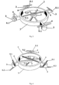
- An aircraft thrust and control system comprises an integral body (1), a central power unit (2) mounted in a central part of the integral body (1), and peripheral power units (3) mounted on branches (4) of the integral body (1).
- the system also comprises other necessary electronic and mechanical components that are well known in the art and are designed to operate, control, and connect the system to the aircraft.
- the central power unit (2) is a relatively high power engine comprising one or more brushless or other types of motors and propellers (5.1, 5.2).
- One or more motors of the central power unit (2) are arranged on one axis, for example one above the other, and the propellers (5.1, 5.2) rotate in opposite directions.
- the propellers (5.1, 5.2) are arranged so that one propeller (5.1), which is the upper one, rotates in a plane different from the plane of rotation of the second propeller (5.2), which is lower one, and parallel to it, and the motor or motors of the two propellers (5.1, 5.2) are located between these planes.
- the two propellers (5.1, 5.2) of the central power units allows allow full compensation of torsional reaction of the two propellers, i.e. no additional aerodynamic compensation measures are required. It also compensates (eliminates) gyroscopic moment, which is undesirable in view of the overall control of the aircraft.
- Peripheral power units (3) are relatively low power units compared to the central power unit (2). Peripheral power units (3) are mainly designed to control the aircraft thrust and control system with respect to horizontal axes of motion X and Z. Each peripheral power unit (3) comprises at least one electric motor, such as a brushless electric motor, and at least one propeller (6.1, 6.2). The peripheral power units (3) are arranged on the branches (4) of the integral body (1), for example at their distal ends, with respect to the central part. Said branches (4) extend radially from the central axis of rotation of the propellers (5.1, 5.2) of the central power unit (2) so that the peripheral power units (3) are located outside of the aerodynamic operating zone of the propellers (5.1, 5.2). All peripheral power units (3) are open-type with propellers (6.1, 6.2) having no side covers, such as an aerodynamic ducts.
- the aircraft thrust and control system comprises an open central power unit (2) with at least one motor and two propellers (5.1, 5.2) arranged as described above and four open peripheral power units (3).
- Peripheral power units (3) have relatively low power compared to the central power unit (2).
- Peripheral power units (3) are mainly designed to control the aircraft thrust and control system with respect to the horizontal axes of motion X and Z.
- Each peripheral power unit (3) comprises one electric motor, such as a brushless electric motor, and one propeller (6.1).
- the peripheral power units (3) are arranged on the branches (4) of the integral body (1), for example at their distal ends with respect to the central part.
- Said branches (4) extend radially from the central axis of rotation of the propellers (5.1, 5.2) of the central power unit (2) so that the peripheral power units (3) are located outside of the aerodynamic operating zone of the propellers (5.1, 5.2).
- All peripheral power units (3) are open-type with propellers (6.1) having no side covers, such as aerodynamic ducts.
- the propellers (6.1) of the peripheral power units (3) operate in essentially the same plane as the upper propeller (5.1) of the central power unit (2). These power units are arranged radially, at 90-degree angular intervals.
- the aircraft thrust and control system comprises the open central power unit (2) with at least one motor and two propellers (5.1, 5.2) arranged as described above, and three peripheral power units (3).
- the peripheral power units (3) are arranged on the branches (4) of the integral body (1), for example at their distal ends, with respect to the central part. Said branches (4) extend radially from the central axis of rotation of the propellers (5.1, 5.2) of the central power unit (2) so that the peripheral power units (3) are located outside of the aerodynamic operating zone of the propellers (5.1, 5.2).
- All peripheral power units (3) are open-type with propellers (6.1, 6.2) having no side covers, such as aerodynamic ducts.
- each of the three peripheral power units (3) is equipped with two electric motors of relatively very low power, one above the other, and propellers (6.1, 6.2) rotating in opposite directions.
- the propellers are arranged so that one propeller (6.1) rotates in one plane that is different from the plane of rotation of the second propeller (6.2).
- the motors of the propellers (6.1, 6.2) are arranged, for example, between such planes.
- the upper propellers (6.1) of the peripheral power units (3) operate in essentially the same plane as the upper propeller (5.1) of the central power unit (2).
- the lower propellers (6.2) of the peripheral power units (3) operate in essentially the same plane as the propeller (5.2) of the central power unit (2).
- the aircraft thrust and control system comprises the central power unit (2) housed in an aerodynamic duct (7) with at least one motor and two propellers (5.1, 5.2) arranged as described above and four open peripheral power units (3).
- Peripheral power units (3) have relatively low power compared to the central power unit (2).
- Peripheral power units (3) are mainly designed to control the aircraft thrust and control system with respect to the horizontal axes of motion X and Z.
- Each peripheral power unit (3) comprises one electric motor, such as a brushless electric motor, and one propeller (6.1).
- the peripheral power units (3) are arranged on the branches (4) of the integral body (1), for example at their distal ends, with respect to the central part.
- Said branches (4) extend radially from the central axis of rotation of the propellers (5.1, 5.2) of the central power unit (2) so that the peripheral power units (3) are located outside of the aerodynamic operating zone of the propellers (5.1, 5.2).
- All peripheral power units (3) are open-type with propellers (6.1) having no side covers, such as aerodynamic ducts.
- the propellers (6.1) of the peripheral power units (3) operate in essentially the same plane as the upper propeller (5.1) of the central power unit (2). These power units are arranged radially, at 90-degree angular intervals.
- the aircraft thrust and control system comprises the central power unit (2) housed in an aerodynamic duct (7) with at least one motor and two propellers (5.1, 5.2) arranged as described above, and three peripheral power units (3).
- the peripheral power units (3) are arranged on the branches (4) of the integral body (1), for example at their distal ends with respect to the central part.
- Said branches (4) extend radially from the central axis of rotation of the propellers (5.1, 5.2) of the central power unit (2) so that the peripheral power units (3) are located outside of the aerodynamic operating zone of the propellers (5.1, 5.2).
- All peripheral power units (3) are open-type with propellers (6.1, 6.2) having no side covers, such as aerodynamic ducts. These power units are arranged radially, at angular intervals of 120 degrees.
- each of the three peripheral power units (3) is equipped with two electric motors of relatively very low power, one above the other, and propellers (6.1, 6.2) rotating in opposite directions.
- the propellers are arranged so that one propeller (6.1) rotates in one plane that is different from the plane of rotation of the other propeller (6.2).
- the motors of the propellers (6.1, 6.2) are arranged, for example, between such planes.
- the upper propellers (6.1) of the peripheral power units (3) operate in essentially the same plane as the upper propeller (5.1) of the central power unit (3).
- the lower propellers (6.2) of the peripheral power units (3) operate in essentially the same plane as the propeller (5.2) of the central power unit (2).
- the central thrust power unit (2) is separated from the peripheral power units (3) so that: the central thrust power unit (2) is not involved at all in controlling the direction of movement of the aircraft thrust and control system in the air.
- the purpose of the central power unit (2) is to create a higher or lower lifting force, thus obtaining better energy parameters of the main thrust. This effect is essentially achieved by using two propellers (5.1, 5.2) of the central power unit (2) rotating in different directions.
- the upper propeller (5.1) of the central power unit (2) and the upper propeller (6.1) of the peripheral power units (3) can be mounted at substantially the same level, approximately at a distance equal to the diameter of the upper propeller (5.1) of the central power unit from the end of the propeller (5.1).
- the lower propeller (5.2) of the central power unit (2) and the lower propellers (6.2) of the peripheral power units (3) can be mounted at substantially the same level, approximately at a distance equal to the diameter of the lower propeller (5.2) of the central power unit from the end of the propeller (5.2).
- the dimensions of the propellers (5.1, 5.2) of the central power unit (2) may be, for example:
- the power units (2, 3) are electrically powered BLDC electric motors and electronically controlled, they are powered by batteries of appropriate capacity.
- the batteries of the peripheral power units (3) are recharged throughout the flight using the energy of the central power unit (2) motor (e.g. internal combustion engine) by rotating the generator (alternator) of the corresponding power.
- the main criterion is generation of the required mechanical torque M to tilt the aircraft with respect to the X and Z axes.
- the aircraft body, or cargo when the aircraft thrust and control system is installed in the aircraft structure, the aircraft body, or cargo, must be located below the control system. This arrangement creates a situation where the center of gravity of the thrust is above the center of gravity of the aircraft, which makes the whole system self-stable with respect to the center of gravity during flight.
- the direction of movement of the aircraft thrust and control system in the air is controlled by varying the rotational speeds of the propellers (6.1, 6.2) of the peripheral power units (3.1, 3.2).
- the central power units (2.1, 2.2) arranged in this way generate about 90% of the upright thrust of the thrust and control system.
- Peripheral power units (6.1, 6.2) arranged in this way generate about 10% of the upright lift of the thrust and control system.
- Thrust distribution percentages are calculated from the total thrust, or the total lifting mass of the aircraft.
Landscapes
- Engineering & Computer Science (AREA)
- Chemical & Material Sciences (AREA)
- Combustion & Propulsion (AREA)
- Aviation & Aerospace Engineering (AREA)
- Mechanical Engineering (AREA)
- Control Of Multiple Motors (AREA)
- Other Liquid Machine Or Engine Such As Wave Power Use (AREA)
Claims (7)
- Schub- und-Steuersystem für Luftfahrzeuge für ein Luftfahrzeug, umfassend eine Rollachse (x), eine Gierachse (y) und eine Neigungsachse (z), wobei das Schub- und-Steuersystem für Luftfahrzeuge eine zentrale Leistungseinheit (2) umfasst, die vom offenen Typ ist oder in einem aerodynamischen Kanal (7) untergebracht ist, wobei die zentrale Leistungseinheit (2) einen oberen Propeller (5.1) und einen unteren Propeller (5.2) umfasst, die übereinander angeordnet sind und dazu ausgelegt sind, sich in entgegengesetzte Richtungen zu drehen, und periphere Leistungseinheiten (3) vom offenen Typ, die jeweils einen oberen Propeller (6.1) oder einen oberen Propeller (6.1) und einen unteren Propeller (6.2) umfassen, wobei sich die peripheren Leistungseinheiten (3) außerhalb des aerodynamischen Betriebsbereiches des oberen und des unteren Propellers (5.1, 5.2) der zentralen Leistungseinheit (2) befinden,wobei die zentrale Leistungseinheit (2) lediglich zum Generieren einer Hubkraft des Luftfahrzeugs in Bezug auf die Gierachse (y) ausgelegt ist,wobei die peripheren Leistungseinheiten (3) zur Steuerung einer Bewegungsrichtung des Luftfahrzeugs in Bezug auf die Roll- (x), die Gier- (y) und die Neigungsachse (z) durch Variieren der Drehzahlen des oberen und des unteren Propellers (6.1, 6.2) ausgelegt sind,wobei die zentrale Leistungseinheit (2) überhaupt nicht am Steuern der Bewegungsrichtung des Luftfahrzeugs beteiligt ist,wobei der obere Propeller (5.1) der zentralen Leistungseinheit (2) in der gleichen Ebene wie jeder obere Propeller (6.1) der peripheren Leistungseinheiten (3) betrieben wird, wenn die peripheren Leistungseinheiten nur mit den oberen Propellern (6.1) ausgestattet sind, undwobei die oberen Propeller (5.1) der zentralen Leistungseinheit (2) in der gleichen Ebene wie jeder obere Propeller (6.1) der peripheren Leistungseinheiten (3) betrieben wird und der untere Propeller (5.2) der Leistungseinheiten (2) in der gleichen Ebene wie jeder untere Propeller (6.2) der peripheren Leistungseinheiten (3) betrieben wird, wenn die peripheren Leistungseinheiten mit oberen Propellern (6.1) und unteren Propellern (6.2) ausgestattet sind.
- Schub- und Steuersystem für Luftfahrzeuge nach Anspruch 1, wobei das System vier periphere Leistungseinheiten (3) umfasst, deren obere Propeller (6.1) dazu ausgelegt sind, in im Wesentlichen der gleichen Ebene wie der obere Propeller (5.1) der zentralen Leistungseinheit (2) betrieben zu werden.
- Schub- und-Steuersystem für Luftfahrzeuge nach Anspruch 1, wobei das System drei periphere Leistungseinheiten (3) umfasst, die jeweils zwei Propeller (6.1, 6.2) umfassen, wobei der obere Propeller (6.1) jeder peripheren Leistungseinheit (3) dazu ausgelegt ist, sich in eine entgegengesetzte Richtung zu drehen als der untere Propeller (6.2) der peripheren Leistungseinheit (3), und wobei der obere Propeller (6.1) jeder peripheren Leistungseinheit (3) dazu ausgelegt ist, sich in einer Ebene zu drehen, die sich von der Drehebene des unteren Propellers (6.2) unterscheidet, und wobei die oberen Propeller (6.1) der peripheren Leistungseinheiten (3) in im Wesentlichen der gleichen Ebene wie der obere Propeller (5.1) der zentralen Leistungseinheit (2) betrieben werden und die unteren Propeller (6.2) der peripheren Leistungseinheiten (3) in im Wesentlichen der gleichen Ebene wie der untere Propeller (5.2) der zentralen Leistungseinheit (2) betrieben werden.
- Schub- und Steuersystem für Luftfahrzeuge nach einem der Ansprüche 1 bis 3, wobei eine Länge der Propeller (5.1, 5.2) der zentralen Leistungseinheit (2) von 0,4 bis 1,5 m beträgt.
- Schub- und Steuersystem für Luftfahrzeuge nach einem der Ansprüche 1 bis 3, wobei eine Länge der Propeller (5.1, 5.2) der zentralen Leistungseinheit (2) von 1,5 bis 4 m beträgt.
- Schub- und Steuersystem für Luftfahrzeuge nach einem der Ansprüche 1 bis 3, wobei eine Länge der Propeller (5.1, 5.2) der zentralen Leistungseinheit (2) mehr als 4 m beträgt.
- Luftfahrzeug, umfassend das Schub- und Steuersystem für Luftfahrzeuge nach einem der vorhergehenden Ansprüche.
Applications Claiming Priority (1)
| Application Number | Priority Date | Filing Date | Title |
|---|---|---|---|
| PCT/IB2020/054978 WO2021240211A1 (en) | 2020-05-26 | 2020-05-26 | Aircraft thrust control system |
Publications (3)
| Publication Number | Publication Date |
|---|---|
| EP4157716A1 EP4157716A1 (de) | 2023-04-05 |
| EP4157716B1 true EP4157716B1 (de) | 2025-02-26 |
| EP4157716C0 EP4157716C0 (de) | 2025-02-26 |
Family
ID=72046942
Family Applications (1)
| Application Number | Title | Priority Date | Filing Date |
|---|---|---|---|
| EP20754353.9A Active EP4157716B1 (de) | 2020-05-26 | 2020-05-26 | Schub- und steuersystem für flugzeuge |
Country Status (4)
| Country | Link |
|---|---|
| US (1) | US12304616B2 (de) |
| EP (1) | EP4157716B1 (de) |
| CN (1) | CN115667071B (de) |
| WO (1) | WO2021240211A1 (de) |
Families Citing this family (1)
| Publication number | Priority date | Publication date | Assignee | Title |
|---|---|---|---|---|
| US20190270516A1 (en) * | 2018-03-01 | 2019-09-05 | Bell Helicopter Textron Inc. | Propulsion Systems for Rotorcraft |
Citations (1)
| Publication number | Priority date | Publication date | Assignee | Title |
|---|---|---|---|---|
| US20170274984A1 (en) * | 2016-03-23 | 2017-09-28 | Amazon Technologies, Inc. | Coaxially aligned propellers of an aerial vehicle |
Family Cites Families (18)
| Publication number | Priority date | Publication date | Assignee | Title |
|---|---|---|---|---|
| DE102005046155B4 (de) * | 2005-09-27 | 2014-02-13 | Emt Ingenieurgesellschaft Dipl.-Ing. Hartmut Euer Mbh | Hubschrauber mit koaxialen Hauptrotoren |
| US20170015417A1 (en) * | 2014-08-29 | 2017-01-19 | Reference Technologies Inc | Multi-Propulsion Design for Unmanned Aerial Systems |
| US10040544B2 (en) * | 2015-01-02 | 2018-08-07 | Jesse Antoine Marcel | Multi-rotor personal air vehicle with a central lifting fan |
| FR3032687B1 (fr) * | 2015-02-16 | 2018-10-12 | Hutchinson | Aerodyne vtol a soufflante(s) axiale(s) porteuse(s) |
| KR101820420B1 (ko) * | 2015-08-10 | 2018-01-22 | 주식회사 성진에어로 | 하이브리드 드론 시스템 |
| US10377483B2 (en) * | 2016-03-01 | 2019-08-13 | Amazon Technologies, Inc. | Six degree of freedom aerial vehicle with offset propulsion mechanisms |
| FR3048956B1 (fr) * | 2016-03-18 | 2019-07-12 | Centre National D'etudes Spatiales C N E S | Aeronef a voilure tournante |
| CN108609165A (zh) * | 2016-12-09 | 2018-10-02 | 北京京东尚科信息技术有限公司 | 无人机 |
| US11608187B2 (en) * | 2017-08-04 | 2023-03-21 | ideaForge Technology Pvt. Ltd | Single arm failure redundancy in a multi-rotor aerial vehicle with least rotors/propellers |
| CA3096122A1 (en) * | 2018-04-09 | 2019-10-17 | PreNav, Inc. | Unmanned aerial vehicles with stereoscopic imaging, and associated systems and methods |
| DE102018210740A1 (de) * | 2018-06-29 | 2020-01-02 | Robert Bosch Gmbh | Flugvorrichtung |
| US20200010193A1 (en) * | 2018-07-04 | 2020-01-09 | Dwight Darwin Alexander | Method and Apparatus for Unmanned Aerial Maritime Float Vehicle That Sense and Report Relevant Data from Physical and Operational Environment |
| US11027836B2 (en) * | 2018-07-13 | 2021-06-08 | The Boeing Company | Rotorcraft with canted coaxial rotors |
| CN109941429A (zh) | 2019-02-19 | 2019-06-28 | 陈健平 | 无人机 |
| FR3103463B1 (fr) * | 2019-11-21 | 2022-06-24 | Safran | Procédé de gestion d’atterrissage d’urgence dans un aéronef VTOL à quatre rotors opposés deux à deux et aéronef VTOL associé |
| CN112441226B (zh) * | 2020-12-10 | 2022-07-08 | 山东交通学院 | 一种用于对船舶进行巡检的复合无人机 |
| KR102308242B1 (ko) * | 2021-05-20 | 2021-10-05 | 주식회사 보라스카이 | 화물수송 드론용 윈치 시스템 및 이의 운용방법 |
| CN116654312A (zh) * | 2023-05-24 | 2023-08-29 | 南京林业大学 | 一种基于无人机的农作物喷药装置 |
-
2020
- 2020-05-26 EP EP20754353.9A patent/EP4157716B1/de active Active
- 2020-05-26 US US17/927,368 patent/US12304616B2/en active Active
- 2020-05-26 CN CN202080101395.8A patent/CN115667071B/zh active Active
- 2020-05-26 WO PCT/IB2020/054978 patent/WO2021240211A1/en not_active Ceased
Patent Citations (1)
| Publication number | Priority date | Publication date | Assignee | Title |
|---|---|---|---|---|
| US20170274984A1 (en) * | 2016-03-23 | 2017-09-28 | Amazon Technologies, Inc. | Coaxially aligned propellers of an aerial vehicle |
Also Published As
| Publication number | Publication date |
|---|---|
| CN115667071A (zh) | 2023-01-31 |
| US12304616B2 (en) | 2025-05-20 |
| WO2021240211A1 (en) | 2021-12-02 |
| US20230202643A1 (en) | 2023-06-29 |
| CN115667071B (zh) | 2025-08-05 |
| EP4157716A1 (de) | 2023-04-05 |
| EP4157716C0 (de) | 2025-02-26 |
Similar Documents
| Publication | Publication Date | Title |
|---|---|---|
| JP7466963B2 (ja) | 大型の可変速ティルトロータを用いたeVTOL航空機 | |
| US12565341B2 (en) | Manned and unmanned aircraft | |
| US11724801B2 (en) | VTOL aircraft having fixed-wing and rotorcraft configurations | |
| US7249732B2 (en) | Aerodynamically stable, VTOL aircraft | |
| US11673676B2 (en) | Hybrid VTOL aerial vehicle | |
| US8128033B2 (en) | System and process of vector propulsion with independent control of three translation and three rotation axis | |
| EP3290334B1 (de) | Flugzeug für vertikales starten und landen | |
| JP5421503B2 (ja) | 自家用航空機 | |
| EP1851109B1 (de) | Schwebe-luftfahrzeug mit doppeltriebwerk | |
| EP2928772B1 (de) | Vertikal startendes und landendes flugzeug | |
| US6575401B1 (en) | Vertical-lift and horizontal flight aircraft | |
| US20170015417A1 (en) | Multi-Propulsion Design for Unmanned Aerial Systems | |
| US20040094662A1 (en) | Vertical tale-off landing hovercraft | |
| WO2004065208A2 (en) | Quiet vertical takeoff and landing aircraft using ducted, magnetic induction air-impeller rotors | |
| WO2021010915A1 (en) | A multi-function unmanned aerial vehicle with tilting co-axial, counter-rotating, folding propeller system | |
| WO2024035711A1 (en) | Aircraft with hybrid parallel and series propulsion system | |
| EP4157716B1 (de) | Schub- und steuersystem für flugzeuge | |
| WO2024209496A1 (en) | Electric coaxial rotor aircraft | |
| RU2845290C1 (ru) | Беспилотный летательный аппарат вертикального взлета и посадки с управляемым вектором тяги | |
| RU2803214C1 (ru) | Мультикоптер с воздушными винтами комбинированного назначения и гибридной двигательной установкой винтомоторных групп | |
| KR20250153849A (ko) | 수직 이착륙 항공기 및 추진 조립체 | |
| WO2020047045A1 (en) | Manned and unmanned aircraft |
Legal Events
| Date | Code | Title | Description |
|---|---|---|---|
| STAA | Information on the status of an ep patent application or granted ep patent |
Free format text: STATUS: UNKNOWN |
|
| STAA | Information on the status of an ep patent application or granted ep patent |
Free format text: STATUS: THE INTERNATIONAL PUBLICATION HAS BEEN MADE |
|
| PUAI | Public reference made under article 153(3) epc to a published international application that has entered the european phase |
Free format text: ORIGINAL CODE: 0009012 |
|
| STAA | Information on the status of an ep patent application or granted ep patent |
Free format text: STATUS: REQUEST FOR EXAMINATION WAS MADE |
|
| 17P | Request for examination filed |
Effective date: 20221122 |
|
| AK | Designated contracting states |
Kind code of ref document: A1 Designated state(s): AL AT BE BG CH CY CZ DE DK EE ES FI FR GB GR HR HU IE IS IT LI LT LU LV MC MK MT NL NO PL PT RO RS SE SI SK SM TR |
|
| DAV | Request for validation of the european patent (deleted) | ||
| DAX | Request for extension of the european patent (deleted) | ||
| REG | Reference to a national code |
Ref country code: DE Ref legal event code: R079 Free format text: PREVIOUS MAIN CLASS: B64C0027080000 Ipc: B64U0030260000 Ref country code: DE Ref legal event code: R079 Ref document number: 602020046780 Country of ref document: DE Free format text: PREVIOUS MAIN CLASS: B64C0027080000 Ipc: B64U0030260000 |
|
| GRAP | Despatch of communication of intention to grant a patent |
Free format text: ORIGINAL CODE: EPIDOSNIGR1 |
|
| STAA | Information on the status of an ep patent application or granted ep patent |
Free format text: STATUS: GRANT OF PATENT IS INTENDED |
|
| RIC1 | Information provided on ipc code assigned before grant |
Ipc: B64C 27/20 20230101ALN20241011BHEP Ipc: B64C 29/00 20060101ALI20241011BHEP Ipc: B64U 30/20 20230101ALI20241011BHEP Ipc: B64U 50/19 20230101ALI20241011BHEP Ipc: B64U 50/14 20230101ALI20241011BHEP Ipc: B64U 50/13 20230101ALI20241011BHEP Ipc: B64U 30/26 20230101AFI20241011BHEP |
|
| RIC1 | Information provided on ipc code assigned before grant |
Ipc: B64C 27/20 20230101ALN20241105BHEP Ipc: B64C 29/00 20060101ALI20241105BHEP Ipc: B64U 30/20 20230101ALI20241105BHEP Ipc: B64U 50/19 20230101ALI20241105BHEP Ipc: B64U 50/14 20230101ALI20241105BHEP Ipc: B64U 50/13 20230101ALI20241105BHEP Ipc: B64U 30/26 20230101AFI20241105BHEP |
|
| INTG | Intention to grant announced |
Effective date: 20241113 |
|
| GRAS | Grant fee paid |
Free format text: ORIGINAL CODE: EPIDOSNIGR3 |
|
| GRAA | (expected) grant |
Free format text: ORIGINAL CODE: 0009210 |
|
| STAA | Information on the status of an ep patent application or granted ep patent |
Free format text: STATUS: THE PATENT HAS BEEN GRANTED |
|
| AK | Designated contracting states |
Kind code of ref document: B1 Designated state(s): AL AT BE BG CH CY CZ DE DK EE ES FI FR GB GR HR HU IE IS IT LI LT LU LV MC MK MT NL NO PL PT RO RS SE SI SK SM TR |
|
| REG | Reference to a national code |
Ref country code: GB Ref legal event code: FG4D |
|
| REG | Reference to a national code |
Ref country code: CH Ref legal event code: EP |
|
| REG | Reference to a national code |
Ref country code: DE Ref legal event code: R096 Ref document number: 602020046780 Country of ref document: DE |
|
| REG | Reference to a national code |
Ref country code: IE Ref legal event code: FG4D |
|
| U01 | Request for unitary effect filed |
Effective date: 20250307 |
|
| U07 | Unitary effect registered |
Designated state(s): AT BE BG DE DK EE FI FR IT LT LU LV MT NL PT RO SE SI Effective date: 20250314 |
|
| U20 | Renewal fee for the european patent with unitary effect paid |
Year of fee payment: 6 Effective date: 20250520 |
|
| PG25 | Lapsed in a contracting state [announced via postgrant information from national office to epo] |
Ref country code: RS Free format text: LAPSE BECAUSE OF FAILURE TO SUBMIT A TRANSLATION OF THE DESCRIPTION OR TO PAY THE FEE WITHIN THE PRESCRIBED TIME-LIMIT Effective date: 20250526 |
|
| PG25 | Lapsed in a contracting state [announced via postgrant information from national office to epo] |
Ref country code: PL Free format text: LAPSE BECAUSE OF FAILURE TO SUBMIT A TRANSLATION OF THE DESCRIPTION OR TO PAY THE FEE WITHIN THE PRESCRIBED TIME-LIMIT Effective date: 20250226 |
|
| PG25 | Lapsed in a contracting state [announced via postgrant information from national office to epo] |
Ref country code: ES Free format text: LAPSE BECAUSE OF FAILURE TO SUBMIT A TRANSLATION OF THE DESCRIPTION OR TO PAY THE FEE WITHIN THE PRESCRIBED TIME-LIMIT Effective date: 20250226 |
|
| PG25 | Lapsed in a contracting state [announced via postgrant information from national office to epo] |
Ref country code: NO Free format text: LAPSE BECAUSE OF FAILURE TO SUBMIT A TRANSLATION OF THE DESCRIPTION OR TO PAY THE FEE WITHIN THE PRESCRIBED TIME-LIMIT Effective date: 20250526 Ref country code: IS Free format text: LAPSE BECAUSE OF FAILURE TO SUBMIT A TRANSLATION OF THE DESCRIPTION OR TO PAY THE FEE WITHIN THE PRESCRIBED TIME-LIMIT Effective date: 20250626 |
|
| PG25 | Lapsed in a contracting state [announced via postgrant information from national office to epo] |
Ref country code: HR Free format text: LAPSE BECAUSE OF FAILURE TO SUBMIT A TRANSLATION OF THE DESCRIPTION OR TO PAY THE FEE WITHIN THE PRESCRIBED TIME-LIMIT Effective date: 20250226 |
|
| PG25 | Lapsed in a contracting state [announced via postgrant information from national office to epo] |
Ref country code: GR Free format text: LAPSE BECAUSE OF FAILURE TO SUBMIT A TRANSLATION OF THE DESCRIPTION OR TO PAY THE FEE WITHIN THE PRESCRIBED TIME-LIMIT Effective date: 20250527 |
|
| PG25 | Lapsed in a contracting state [announced via postgrant information from national office to epo] |
Ref country code: SM Free format text: LAPSE BECAUSE OF FAILURE TO SUBMIT A TRANSLATION OF THE DESCRIPTION OR TO PAY THE FEE WITHIN THE PRESCRIBED TIME-LIMIT Effective date: 20250226 |
|
| PG25 | Lapsed in a contracting state [announced via postgrant information from national office to epo] |
Ref country code: CZ Free format text: LAPSE BECAUSE OF FAILURE TO SUBMIT A TRANSLATION OF THE DESCRIPTION OR TO PAY THE FEE WITHIN THE PRESCRIBED TIME-LIMIT Effective date: 20250226 |
|
| PG25 | Lapsed in a contracting state [announced via postgrant information from national office to epo] |
Ref country code: SK Free format text: LAPSE BECAUSE OF FAILURE TO SUBMIT A TRANSLATION OF THE DESCRIPTION OR TO PAY THE FEE WITHIN THE PRESCRIBED TIME-LIMIT Effective date: 20250226 |
|
| REG | Reference to a national code |
Ref country code: CH Ref legal event code: H13 Free format text: ST27 STATUS EVENT CODE: U-0-0-H10-H13 (AS PROVIDED BY THE NATIONAL OFFICE) Effective date: 20251223 |
|
| PLBE | No opposition filed within time limit |
Free format text: ORIGINAL CODE: 0009261 |
|
| STAA | Information on the status of an ep patent application or granted ep patent |
Free format text: STATUS: NO OPPOSITION FILED WITHIN TIME LIMIT |
|
| PG25 | Lapsed in a contracting state [announced via postgrant information from national office to epo] |
Ref country code: CH Free format text: LAPSE BECAUSE OF NON-PAYMENT OF DUE FEES Effective date: 20250531 |
|
| GBPC | Gb: european patent ceased through non-payment of renewal fee |
Effective date: 20250526 |
|
| PG25 | Lapsed in a contracting state [announced via postgrant information from national office to epo] |
Ref country code: MC Free format text: LAPSE BECAUSE OF FAILURE TO SUBMIT A TRANSLATION OF THE DESCRIPTION OR TO PAY THE FEE WITHIN THE PRESCRIBED TIME-LIMIT Effective date: 20250226 |
|
| 26N | No opposition filed |
Effective date: 20251127 |