EP4157685B1 - Improved boosted brake control hydraulic arrangement for work vehicles - Google Patents
Improved boosted brake control hydraulic arrangement for work vehicles Download PDFInfo
- Publication number
- EP4157685B1 EP4157685B1 EP21726688.1A EP21726688A EP4157685B1 EP 4157685 B1 EP4157685 B1 EP 4157685B1 EP 21726688 A EP21726688 A EP 21726688A EP 4157685 B1 EP4157685 B1 EP 4157685B1
- Authority
- EP
- European Patent Office
- Prior art keywords
- port
- valve
- brakes
- hydraulic arrangement
- fluid
- Prior art date
- Legal status (The legal status is an assumption and is not a legal conclusion. Google has not performed a legal analysis and makes no representation as to the accuracy of the status listed.)
- Active
Links
Images

Classifications
-
- B—PERFORMING OPERATIONS; TRANSPORTING
- B60—VEHICLES IN GENERAL
- B60T—VEHICLE BRAKE CONTROL SYSTEMS OR PARTS THEREOF; BRAKE CONTROL SYSTEMS OR PARTS THEREOF, IN GENERAL; ARRANGEMENT OF BRAKING ELEMENTS ON VEHICLES IN GENERAL; PORTABLE DEVICES FOR PREVENTING UNWANTED MOVEMENT OF VEHICLES; VEHICLE MODIFICATIONS TO FACILITATE COOLING OF BRAKES
- B60T13/00—Transmitting braking action from initiating means to ultimate brake actuator with power assistance or drive; Brake systems incorporating such transmitting means, e.g. air-pressure brake systems
- B60T13/10—Transmitting braking action from initiating means to ultimate brake actuator with power assistance or drive; Brake systems incorporating such transmitting means, e.g. air-pressure brake systems with fluid assistance, drive, or release
- B60T13/12—Transmitting braking action from initiating means to ultimate brake actuator with power assistance or drive; Brake systems incorporating such transmitting means, e.g. air-pressure brake systems with fluid assistance, drive, or release the fluid being liquid
- B60T13/14—Transmitting braking action from initiating means to ultimate brake actuator with power assistance or drive; Brake systems incorporating such transmitting means, e.g. air-pressure brake systems with fluid assistance, drive, or release the fluid being liquid using accumulators or reservoirs fed by pumps
- B60T13/142—Systems with master cylinder
-
- B—PERFORMING OPERATIONS; TRANSPORTING
- B60—VEHICLES IN GENERAL
- B60T—VEHICLE BRAKE CONTROL SYSTEMS OR PARTS THEREOF; BRAKE CONTROL SYSTEMS OR PARTS THEREOF, IN GENERAL; ARRANGEMENT OF BRAKING ELEMENTS ON VEHICLES IN GENERAL; PORTABLE DEVICES FOR PREVENTING UNWANTED MOVEMENT OF VEHICLES; VEHICLE MODIFICATIONS TO FACILITATE COOLING OF BRAKES
- B60T11/00—Transmitting braking action from initiating means to ultimate brake actuator without power assistance or drive or where such assistance or drive is irrelevant
- B60T11/10—Transmitting braking action from initiating means to ultimate brake actuator without power assistance or drive or where such assistance or drive is irrelevant transmitting by fluid means, e.g. hydraulic
- B60T11/16—Master control, e.g. master cylinders
- B60T11/20—Tandem, side-by-side, or other multiple master cylinder units
- B60T11/21—Tandem, side-by-side, or other multiple master cylinder units with two pedals operating on respective circuits, pressures therein being equalised when both pedals are operated together, e.g. for steering
-
- B—PERFORMING OPERATIONS; TRANSPORTING
- B60—VEHICLES IN GENERAL
- B60T—VEHICLE BRAKE CONTROL SYSTEMS OR PARTS THEREOF; BRAKE CONTROL SYSTEMS OR PARTS THEREOF, IN GENERAL; ARRANGEMENT OF BRAKING ELEMENTS ON VEHICLES IN GENERAL; PORTABLE DEVICES FOR PREVENTING UNWANTED MOVEMENT OF VEHICLES; VEHICLE MODIFICATIONS TO FACILITATE COOLING OF BRAKES
- B60T13/00—Transmitting braking action from initiating means to ultimate brake actuator with power assistance or drive; Brake systems incorporating such transmitting means, e.g. air-pressure brake systems
- B60T13/10—Transmitting braking action from initiating means to ultimate brake actuator with power assistance or drive; Brake systems incorporating such transmitting means, e.g. air-pressure brake systems with fluid assistance, drive, or release
- B60T13/12—Transmitting braking action from initiating means to ultimate brake actuator with power assistance or drive; Brake systems incorporating such transmitting means, e.g. air-pressure brake systems with fluid assistance, drive, or release the fluid being liquid
- B60T13/16—Transmitting braking action from initiating means to ultimate brake actuator with power assistance or drive; Brake systems incorporating such transmitting means, e.g. air-pressure brake systems with fluid assistance, drive, or release the fluid being liquid using pumps directly, i.e. without interposition of accumulators or reservoirs
- B60T13/161—Systems with master cylinder
- B60T13/162—Master cylinder mechanically coupled with booster
Definitions
- the present invention concerns a brake control hydraulic arrangement, in particular a boosted brake control hydraulic arrangement for master brake cylinders of work vehicles, such as agricultural vehicles.
- WO2016/139182A1 dicloses an example of such hydraulic arrangement.
- the fluid coming from master brake cylinder 5' is also used for controlling front brakes 8' of the work vehicle thanks to an "AND" valve 9' fluidly interposed in parallel between the lines coming from master brake cylinder 5' and directed to rear brakes 6'.
- the above synthetically defined arrangement is known as boosted master brake cylinder configuration and it is widely used in work vehicles to assist the operator when braking the vehicle.
- master braked cylinders of a hydraulic arrangement as the one disclosed in figure 1 needs to be over dimensioned and may lead to problems when the same master braked cylinders of a hydraulic arrangement is used in vehicles with or without front brakes, that is not present in all vehicles.
- An aim of the present invention is to satisfy the above mentioned needs in an economic and optimized way.
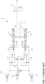
- FIG. 1 generically discloses a hydraulic arrangement according to the present invention and configured to control the actuation of rear brakes 2a, 2b of a work vehicle, not shown.
- the hydraulic arrangement 1 is configured to control a rear left brake 2a and a rear right brake 2b of the work vehicle.
- Hydraulic arrangement 1 comprises a master brake cylinder module 3 comprising a master brake cylinder 4a, 4b for each of the rear brake 2a, 2b and a respective actuation valve 5a, 5b for each of such master brake cylinders 4a, 4b.
- the disclosed exemplarily master brake cylinder module 3 comprises the same elements for left rear brake 2a and right rear brake 2b, only the elements for operating the left rear brake 2a will be described, assuming the index "a" together the reference number. The same elements with index "b" are present for operating the right rear brake 2b.
- the master brake cylinder 4a comprises a housing 6a and a piston 7a configured to slide inside the housing 6a that is further configured to house fluid in pressure.
- the housing 6a is fluidly connected via a conduit 8a to the left rear brake 2a. Indeed a motion of the piston 7a inside the housing 6a tends to push away through conduit 8a the fluid in pressure thereby activating the left rear brake 2a.
- hydraulic arrangement 1 further comprises a source 10 of fluid in pressure fluidly connected to valve 5a.
- the source 10 comprises a single accumulator 11 but it's clear that the source may be separated for each left and right rear brake 2a, 2b or may be provided with a different and more complex hydraulic arrangement.
- the source 10 is fluidly connected to a first port 5a' of actuation valve 5a via a conduit 15; indeed it's separated then into two branches 15a, 15b to be connected to each actuation valve 5a, 5b.
- a second port 5a " actuation valve 5a is fluidly connected via a conduit 16a to allow a hydraulic signal to exert a hydraulic pressure, in parallel to mechanical pedal 9a.
- Such hydraulic signal is selectively connected by connecting the second port 5a " to the first port 5a' of actuation valve 5a, as described below.
- the hydraulic signal can vary from zero in a first position of the actuation valve 5a to a maximum value in a further position of the actuation valve 5a proportionally at the pedal load applied.
- second port 5a'' i.e. conduit 16a
- conduit 16a may further be fluidly connected to output conduit 8a of housing 6a of master bake cylinder 4a via a related conduit 17a.
- the hydraulic arrangement 1 comprises an intermediate valve 18a rigidly carried by actuation valve 5a configured to allow the passage of fluid between the actuation valve 5a and the housing 16a in both directions or to allow the passage of such fluid in only one direction, e.g. from actuation valve 5a to housing 16.
- the conduit 17a comprises a central portion into which is divided into two branches and the intermediate valve 18a is fluidly interposed between such branches. Accordingly, such intermediate valve 18a is a two-position four ways valve.
- actuation valve 5a further defines a third port 5a′′′ fluidly connected to discharge 19.
- actuation valve 5a is a three ways proportional valve.
- actuation valve 5a can assume at least a first position into which the second port 5a " is connected to its third port 5a′′′ and a second position into which the second port 5a " is fluidly connected to the first port 5a'.
- hydraulic arrangement 1 further comprises pressure balancing means 20 fluidly interposed between the housings 6a of the master cylinders 4a, 4b and here not described in detail for sake of brevity.
- conduits 17a, 17b are isolated and second port 5a " , 5b " is sent to shuttle valve 21.
- both hydraulic signals come from the left or right sides of the master cylinder module 3, then a common hydraulic signal is sent to the front brakes 22, thereby activating these latter. Such activation may be more or less delayed in function of the brake design.
- the proposed hydraulic arrangement 1 can be used for different typologies of vehicle already comprising booster master brake cylinder modules for controlling rear brakes with minimal modifications.
- front brakes 22 to rear brakes 2a, 2b does not modify the pedal stroke needed to activate rear brakes 2a, 2b.
Landscapes
- Engineering & Computer Science (AREA)
- Transportation (AREA)
- Mechanical Engineering (AREA)
- Braking Systems And Boosters (AREA)
- Transmission Of Braking Force In Braking Systems (AREA)
Description
- The present invention concerns a brake control hydraulic arrangement, in particular a boosted brake control hydraulic arrangement for master brake cylinders of work vehicles, such as agricultural vehicles.
- All vehicles are provided with brakes and, as known, work vehicles such as agricultural vehicles are provided with main brakes on rear wheels of the vehicle that can be actuated hydraulically e.g. thanks to dedicated master brake cylinders and further, optional, brakes on front wheels of the vehicles that can be actuated hydraulically thanks to the same master brake cylinders.
-
WO2016/139182A1 dicloses an example of such hydraulic arrangement. -
Figure 1 discloses an exemplarily embodiment of rear brakes control hydraulic arrangement 1' as known in the art. Briefly, such arrangement 1' comprises a brake actuation valve 2' configured to be actuated by a respective pedal 3' by the user of the work vehicle. Such brake actuation valve 2' is configured to move a piston 4' making part of a master brake cylinder 5' which consequently push a high pressure fluid into a respective brake 6'. - In order to facilitate the pushing operation of the pedal 3' by the user of the work vehicle, it is known to hydraulically connect a source of fluid in pressure 7' to the servo-brake actuation valve 2' so that the greater is the pushing on the pedal 3', the greater fluid in pressure helps the movement of the brake actuation valve 2' to actuate the master brake cylinder 5'.
- It is noted that the fluid coming from master brake cylinder 5' is also used for controlling front brakes 8' of the work vehicle thanks to an "AND" valve 9' fluidly interposed in parallel between the lines coming from master brake cylinder 5' and directed to rear brakes 6'.
- The above synthetically defined arrangement is known as boosted master brake cylinder configuration and it is widely used in work vehicles to assist the operator when braking the vehicle.
- However, it is clear that the above configuration needs to have master brake cylinders normally dimensioned to have enough fluid volume to actuate rear brakes but also front brakes when they are provided. This result in criticality manage the different configuration with same master cylinder volume.
- Accordingly, master braked cylinders of a hydraulic arrangement as the one disclosed in
figure 1 needs to be over dimensioned and may lead to problems when the same master braked cylinders of a hydraulic arrangement is used in vehicles with or without front brakes, that is not present in all vehicles. - Therefore, the need is felt to provide a hydraulic arrangement configured to allow the activation of rear and front brakes of a work vehicle in a cost effective, compact and lighter way, with the opportunity to have in the same time a potential second line of braking (secondary brake)
- An aim of the present invention is to satisfy the above mentioned needs in an economic and optimized way.
- The aforementioned aim is reached by a hydraulic arrangement and a work vehicle as claimed in the appended set of claims.
- For a better understanding of the present invention, a preferred embodiment is described in the following, by way of a non-limiting example, with reference to the attached drawings wherein:
-
Figure 1 is a schematic representation of a hydraulic arrangement as known in the prior art; -
Figure 2 is a schematic representation of an embodiment of a hydraulic arrangement according to the present invention. - In
figure 2 reference number, 1 generically discloses a hydraulic arrangement according to the present invention and configured to control the actuation ofrear brakes hydraulic arrangement 1 is configured to control a rearleft brake 2a and a rearright brake 2b of the work vehicle. -
Hydraulic arrangement 1 comprises a masterbrake cylinder module 3 comprising amaster brake cylinder 4a, 4b for each of therear brake respective actuation valve master brake cylinders 4a, 4b. - In the following, since the disclosed exemplarily master
brake cylinder module 3 comprises the same elements for leftrear brake 2a and rightrear brake 2b, only the elements for operating the leftrear brake 2a will be described, assuming the index "a" together the reference number. The same elements with index "b" are present for operating the rightrear brake 2b. - The
master brake cylinder 4a comprises ahousing 6a and apiston 7a configured to slide inside thehousing 6a that is further configured to house fluid in pressure. Thehousing 6a is fluidly connected via aconduit 8a to the leftrear brake 2a. Indeed a motion of thepiston 7a inside thehousing 6a tends to push away throughconduit 8a the fluid in pressure thereby activating the leftrear brake 2a. - The
piston 7a is mechanically connected toactuation valve 5a so that its motion corresponds to a motion ofactuation valve 5a. This latter is actuated by apedal 9a so that the user, by pushing thepedal 9a, can move theactuation valve 5a thereby inserting thepiston 7a into thehousing 6a. - In order to provide the aforementioned boost function to
actuation valve 5a,hydraulic arrangement 1 further comprises asource 10 of fluid in pressure fluidly connected tovalve 5a. It should be noted that in the disclosed embodiment thesource 10 comprises asingle accumulator 11 but it's clear that the source may be separated for each left and rightrear brake - The
accumulator 11 is fluidly connected to a source of fluid inpressure 12 of the work vehicle, e.g. a pump, via aconduit 13 into which it is interposed acheck valve 14 to avoid contrary passage of fluid fromcircuit 1 to thesource 12. - As said, the
source 10 is fluidly connected to afirst port 5a' ofactuation valve 5a via aconduit 15; indeed it's separated then into twobranches actuation valve - Moreover, a
second port 5a" actuation valve 5a is fluidly connected via aconduit 16a to allow a hydraulic signal to exert a hydraulic pressure, in parallel tomechanical pedal 9a. Such hydraulic signal is selectively connected by connecting thesecond port 5a" to thefirst port 5a' ofactuation valve 5a, as described below. In particular. As clearly shown, the hydraulic signal can vary from zero in a first position of theactuation valve 5a to a maximum value in a further position of theactuation valve 5a proportionally at the pedal load applied. - Furthermore,
second port 5a'', i.e.conduit 16a, may further be fluidly connected tooutput conduit 8a ofhousing 6a ofmaster bake cylinder 4a via arelated conduit 17a. In particular and preferably, thehydraulic arrangement 1 comprises anintermediate valve 18a rigidly carried byactuation valve 5a configured to allow the passage of fluid between theactuation valve 5a and thehousing 16a in both directions or to allow the passage of such fluid in only one direction, e.g. fromactuation valve 5a to housing 16. - More preferably, the
conduit 17a comprises a central portion into which is divided into two branches and theintermediate valve 18a is fluidly interposed between such branches. Accordingly, suchintermediate valve 18a is a two-position four ways valve. - Furthermore,
actuation valve 5a further defines athird port 5a‴ fluidly connected todischarge 19. According to the above-defined structure,actuation valve 5a is a three ways proportional valve. Inparticular actuation valve 5a can assume at least a first position into which thesecond port 5a" is connected to itsthird port 5a‴ and a second position into which thesecond port 5a" is fluidly connected to thefirst port 5a'. - As per se known,
hydraulic arrangement 1 further comprises pressure balancing means 20 fluidly interposed between thehousings 6a of themaster cylinders 4a, 4b and here not described in detail for sake of brevity. - According to the invention, the
hydraulic arrangement 1 comprises an "AND"valve 21, e.g. a shuttle valve, fluidly interposed in parallel between thethird ports 5a‴, 5b‴ of eachactuation valve 5. -
Such shuttle valve 21 is configured to allow the passage of the hydraulic flow towardsfront brakes 22 only if both the ones coming fromports 5a‴, 5b‴ are coming toshuttle valve 21. Therefore,shuttle valve 21 acts as an "AND" logic valve in order to actuate thefront brakes 22. - The operation of the above-described embodiment according to the invention is the following.
- When the user of the work vehicle presses the
related pedal piston housing brakes conduit pedal first port 5a‴, 5b‴′ to discharge 19 and viaconduits source 10 viaconduit conduit 15 strength the hydraulic signal acting in parallel topedal pedal conduit 16a helps the user while pressingpedal - Accordingly,
conduits second port 5a", 5b" is sent toshuttle valve 21. Here, if both hydraulic signals come from the left or right sides of themaster cylinder module 3, then a common hydraulic signal is sent to thefront brakes 22, thereby activating these latter. Such activation may be more or less delayed in function of the brake design. - When the user stops to push on the
pedal housing piston first port 5a', 5b' andthird port 5a‴, 5b‴. In particular,pedals - In such way, since
third port 5a‴ is connected to discharge it is closed the passage with the source offluid 10, any possible residual fluid present intoconduit shuttle valve 21 are discharged to discharge 19 so that all front and relatedrear brakes - In view of the foregoing, the advantages of a
hydraulic arrangement 1 according to the invention are apparent. - In particular the proposed
hydraulic arrangement 1 can be used for different typologies of vehicle already comprising booster master brake cylinder modules for controlling rear brakes with minimal modifications. - Indeed, the addition of
front brakes 22 torear brakes rear brakes - Accordingly, all work vehicles can be equipped with smaller
master brake cylinders 4a, 4b irrespectively from the fact they comprise, or not, front brakes, thereby reducing the cost for manufacturing such work vehicles. Indeed, the fluid used for actuating the front brakes comes from the source of fluid in pressure and not from master cylinders whose fluid is only used for rear brakes. - It is clear that modifications can be made to the described
hydraulic arrangement 1 which do not extend beyond the scope of protection defined by the claims. - For example, as said in the description, the master
bake cylinder module 3, theactuation valve 5, the source of fluid inpressure 10, the intermediate valve 18 or theshuttle valve 21 can be of any typology suitable to accomplish their operation as claimed.
Claims (5)
- Hydraulic arrangement (1) for controlling front and rear brakes (22; 2a, 2b) of a work vehicle comprising a master brake cylinder module (3) and a source (10; 12) of fluid in pressure, said master brake cylinder module (3) comprising: a right and a left master cylinders (4a,4b),- at least a master cylinder (4a, 4b) is fluidly connected to rear brakes (2a, 2b);- an actuation valve (5a, 5b) for each of said right and left master cylinders (4a, 4b), said actuation valve (5a, 5b) controlling the fluid flow sent from said right and left master cylinders (4a, 4b) to said brakes (2a, 2b) in function of a force exerted on a pedal (9a, 9b);each actuation valve (5a, 5b) comprises a first port (5a', 5b'), a second port (5a", 5b") and a third port (5a‴, 5b‴), the first port being fluidly connected to said source (10; 12), the second port (5a", 5b") being fluidly connected to said actuation valve (5a, 5b) to exert a pressure on said actuation valve (5a, 5b) in addition to the force exerted on said pedal (9a, 9b), the third port (5a‴, 5b‴) being fluidly connected to a discharge (19),each actuation valve (5a, 5b) being configured to pass between a first position into which said first port (5a', 5b') is fluidly connected to said third port (5a‴, 5b‴) and said second port (5a", 5b") is closed and a second position into which said first port (5a', 5b') is fluidly connected to said second port (5a", 5b") and said third port (5a‴, 5b‴) is closed, said hydraulic arrangement (1) further comprising an "AND" valve (21) fluidly interposed between said second ports (5a", 5b") of said actuation valves (5a, 5b) and said front brakes (22).
- Hydraulic arrangement according to claim 1, wherein said "AND" valve (21) is a shuttle valve.
- Hydraulic arrangement according to claim 1 or 2, further comprising an intermediate valve (18a, 18b) for each of said actuation valve (5a, 5b) and fluidly interposed between conduits (16a, 16b) fluidly connecting said second port (5a",5b") to said actuation valve (5a, 5b) and conduits (8a, 8b) each one fluidly connecting one of the master cylinders (4a, 4b) to said brakes (2a, 2b), said intermediate valve (18a, 18b) being configured to allow the passage of fluid in both direction between said conduits (8a, 8b; 16a, 16b) or to allow the passage of fluid only from said actuation valve (5a, 5b) towards the rear brakes (2a, 2b).
- Hydraulic arrangement according to claim 1 or 2, wherein the right master cylinder (4a) and left master cylinder (4b) are fluidly connected by a respective conduit (8a, 8b) to a respective rear brake (2a, 2b).
- Work vehicle comprising rear brakes (2a, 2b) and front brakes (22) for braking said work vehicle, a source (12) of fluid in pressure and a hydraulic arrangement (1) according to any of the preceding claims for controlling said front and rear brakes (22; 2a, 2b) .
Applications Claiming Priority (2)
| Application Number | Priority Date | Filing Date | Title |
|---|---|---|---|
| IT102020000012430A IT202000012430A1 (en) | 2020-05-26 | 2020-05-26 | IMPROVED HYDRAULIC ARRANGEMENT FOR CONTROLLING A WORK VEHICLE BRAKE BOOSTER |
| PCT/EP2021/063981 WO2021239779A1 (en) | 2020-05-26 | 2021-05-26 | Improved boosted brake control hydraulic arrangement for work vehicles |
Publications (2)
| Publication Number | Publication Date |
|---|---|
| EP4157685A1 EP4157685A1 (en) | 2023-04-05 |
| EP4157685B1 true EP4157685B1 (en) | 2024-07-10 |
Family
ID=71994991
Family Applications (1)
| Application Number | Title | Priority Date | Filing Date |
|---|---|---|---|
| EP21726688.1A Active EP4157685B1 (en) | 2020-05-26 | 2021-05-26 | Improved boosted brake control hydraulic arrangement for work vehicles |
Country Status (3)
| Country | Link |
|---|---|
| EP (1) | EP4157685B1 (en) |
| IT (1) | IT202000012430A1 (en) |
| WO (1) | WO2021239779A1 (en) |
Families Citing this family (2)
| Publication number | Priority date | Publication date | Assignee | Title |
|---|---|---|---|---|
| EP4448354A1 (en) * | 2021-12-17 | 2024-10-23 | ZF Off-Highway Solutions Minnesota Inc. | Full power brake valve with offset in brake pressure |
| US20260116360A1 (en) | 2024-10-25 | 2026-04-30 | Zf Off-Highway Solutions Minnesota Inc. | Dual brake valve |
Family Cites Families (5)
| Publication number | Priority date | Publication date | Assignee | Title |
|---|---|---|---|---|
| WO2008001208A2 (en) * | 2006-06-28 | 2008-01-03 | Studio Tecnico 6M S.R.L. | Pedal steering operating apparatus |
| WO2016139182A1 (en) * | 2015-03-04 | 2016-09-09 | Agco International Gmbh | A braking system |
| IT201800006929A1 (en) * | 2018-07-04 | 2020-01-04 | HYDRAULIC BRAKING ARRANGEMENT FOR OFF-ROAD VEHICLES | |
| IT201800007831A1 (en) * | 2018-08-03 | 2020-02-03 | Cnh Ind Italia Spa | POWER VALVE FOR BRAKES |
| US20200047738A1 (en) * | 2018-08-13 | 2020-02-13 | Cnh Industrial America Llc | System and method for providing brake-assisted steering to a work vehicle based on work vehicle wheel speeds |
-
2020
- 2020-05-26 IT IT102020000012430A patent/IT202000012430A1/en unknown
-
2021
- 2021-05-26 WO PCT/EP2021/063981 patent/WO2021239779A1/en not_active Ceased
- 2021-05-26 EP EP21726688.1A patent/EP4157685B1/en active Active
Also Published As
| Publication number | Publication date |
|---|---|
| EP4157685A1 (en) | 2023-04-05 |
| WO2021239779A1 (en) | 2021-12-02 |
| IT202000012430A1 (en) | 2021-11-26 |
Similar Documents
| Publication | Publication Date | Title |
|---|---|---|
| CN102971192B (en) | Hydraulic assembly for a vehicle brake system | |
| US4449369A (en) | Power assisted hydraulic control system | |
| US11945419B2 (en) | Brake system and motor vehicle | |
| KR101540135B1 (en) | Brake system for motor vehicles | |
| US11964644B2 (en) | Method for operating a brake system, and brake system | |
| US20250042380A1 (en) | Electrohydraulic brake control device for a motor vehicle, and brake system | |
| EP4157685B1 (en) | Improved boosted brake control hydraulic arrangement for work vehicles | |
| GB2170286A (en) | Brake system with slip control | |
| KR20160088382A (en) | Brake system for motor vehicles | |
| US20120326492A1 (en) | Brake system having a pressure modulation cylinder | |
| JPH02258458A (en) | Brake | |
| GB1183825A (en) | Improvements in or relating to Hydraulic Systems. | |
| CN116080611A (en) | Brake system for a vehicle | |
| JPS6366702B2 (en) | ||
| US10132057B2 (en) | Traveling working machine | |
| EP4172010B1 (en) | Improved boosted brake control hydraulic arrangement for work vehicles | |
| JPH0637162B2 (en) | Vehicle braking force control device | |
| GB2128279A (en) | Hydraulic brake master cylinder and booster arrangement | |
| CN108016420A (en) | Master cylinder structure of electronic wire control brake system | |
| GB2160607A (en) | A vehicular hydraulic brake system | |
| GB2084676A (en) | Failsafe operation of hydraulic brake pressure booster | |
| US5005918A (en) | Automotive vehicle brake system | |
| JPH031183B2 (en) | ||
| US4076323A (en) | Fluid brake system for a vehicle | |
| GB2084276A (en) | Brake force booster |
Legal Events
| Date | Code | Title | Description |
|---|---|---|---|
| STAA | Information on the status of an ep patent application or granted ep patent |
Free format text: STATUS: UNKNOWN |
|
| STAA | Information on the status of an ep patent application or granted ep patent |
Free format text: STATUS: THE INTERNATIONAL PUBLICATION HAS BEEN MADE |
|
| PUAI | Public reference made under article 153(3) epc to a published international application that has entered the european phase |
Free format text: ORIGINAL CODE: 0009012 |
|
| STAA | Information on the status of an ep patent application or granted ep patent |
Free format text: STATUS: REQUEST FOR EXAMINATION WAS MADE |
|
| 17P | Request for examination filed |
Effective date: 20230102 |
|
| AK | Designated contracting states |
Kind code of ref document: A1 Designated state(s): AL AT BE BG CH CY CZ DE DK EE ES FI FR GB GR HR HU IE IS IT LI LT LU LV MC MK MT NL NO PL PT RO RS SE SI SK SM TR |
|
| DAV | Request for validation of the european patent (deleted) | ||
| DAX | Request for extension of the european patent (deleted) | ||
| GRAP | Despatch of communication of intention to grant a patent |
Free format text: ORIGINAL CODE: EPIDOSNIGR1 |
|
| STAA | Information on the status of an ep patent application or granted ep patent |
Free format text: STATUS: GRANT OF PATENT IS INTENDED |
|
| INTG | Intention to grant announced |
Effective date: 20231221 |
|
| GRAS | Grant fee paid |
Free format text: ORIGINAL CODE: EPIDOSNIGR3 |
|
| GRAA | (expected) grant |
Free format text: ORIGINAL CODE: 0009210 |
|
| STAA | Information on the status of an ep patent application or granted ep patent |
Free format text: STATUS: THE PATENT HAS BEEN GRANTED |
|
| AK | Designated contracting states |
Kind code of ref document: B1 Designated state(s): AL AT BE BG CH CY CZ DE DK EE ES FI FR GB GR HR HU IE IS IT LI LT LU LV MC MK MT NL NO PL PT RO RS SE SI SK SM TR |
|
| REG | Reference to a national code |
Ref country code: CH Ref legal event code: EP |
|
| REG | Reference to a national code |
Ref country code: DE Ref legal event code: R096 Ref document number: 602021015508 Country of ref document: DE |
|
| REG | Reference to a national code |
Ref country code: LT Ref legal event code: MG9D |
|
| REG | Reference to a national code |
Ref country code: NL Ref legal event code: MP Effective date: 20240710 |
|
| PG25 | Lapsed in a contracting state [announced via postgrant information from national office to epo] |
Ref country code: PT Free format text: LAPSE BECAUSE OF FAILURE TO SUBMIT A TRANSLATION OF THE DESCRIPTION OR TO PAY THE FEE WITHIN THE PRESCRIBED TIME-LIMIT Effective date: 20241111 |
|
| REG | Reference to a national code |
Ref country code: AT Ref legal event code: MK05 Ref document number: 1701803 Country of ref document: AT Kind code of ref document: T Effective date: 20240710 |
|
| PG25 | Lapsed in a contracting state [announced via postgrant information from national office to epo] |
Ref country code: NL Free format text: LAPSE BECAUSE OF FAILURE TO SUBMIT A TRANSLATION OF THE DESCRIPTION OR TO PAY THE FEE WITHIN THE PRESCRIBED TIME-LIMIT Effective date: 20240710 |
|
| PG25 | Lapsed in a contracting state [announced via postgrant information from national office to epo] |
Ref country code: PT Free format text: LAPSE BECAUSE OF FAILURE TO SUBMIT A TRANSLATION OF THE DESCRIPTION OR TO PAY THE FEE WITHIN THE PRESCRIBED TIME-LIMIT Effective date: 20241111 Ref country code: NL Free format text: LAPSE BECAUSE OF FAILURE TO SUBMIT A TRANSLATION OF THE DESCRIPTION OR TO PAY THE FEE WITHIN THE PRESCRIBED TIME-LIMIT Effective date: 20240710 |
|
| PG25 | Lapsed in a contracting state [announced via postgrant information from national office to epo] |
Ref country code: NO Free format text: LAPSE BECAUSE OF FAILURE TO SUBMIT A TRANSLATION OF THE DESCRIPTION OR TO PAY THE FEE WITHIN THE PRESCRIBED TIME-LIMIT Effective date: 20241010 |
|
| PG25 | Lapsed in a contracting state [announced via postgrant information from national office to epo] |
Ref country code: FI Free format text: LAPSE BECAUSE OF FAILURE TO SUBMIT A TRANSLATION OF THE DESCRIPTION OR TO PAY THE FEE WITHIN THE PRESCRIBED TIME-LIMIT Effective date: 20240710 Ref country code: GR Free format text: LAPSE BECAUSE OF FAILURE TO SUBMIT A TRANSLATION OF THE DESCRIPTION OR TO PAY THE FEE WITHIN THE PRESCRIBED TIME-LIMIT Effective date: 20241011 Ref country code: PL Free format text: LAPSE BECAUSE OF FAILURE TO SUBMIT A TRANSLATION OF THE DESCRIPTION OR TO PAY THE FEE WITHIN THE PRESCRIBED TIME-LIMIT Effective date: 20240710 |
|
| PG25 | Lapsed in a contracting state [announced via postgrant information from national office to epo] |
Ref country code: BG Free format text: LAPSE BECAUSE OF FAILURE TO SUBMIT A TRANSLATION OF THE DESCRIPTION OR TO PAY THE FEE WITHIN THE PRESCRIBED TIME-LIMIT Effective date: 20240710 |
|
| PG25 | Lapsed in a contracting state [announced via postgrant information from national office to epo] |
Ref country code: LV Free format text: LAPSE BECAUSE OF FAILURE TO SUBMIT A TRANSLATION OF THE DESCRIPTION OR TO PAY THE FEE WITHIN THE PRESCRIBED TIME-LIMIT Effective date: 20240710 |
|
| PG25 | Lapsed in a contracting state [announced via postgrant information from national office to epo] |
Ref country code: AT Free format text: LAPSE BECAUSE OF FAILURE TO SUBMIT A TRANSLATION OF THE DESCRIPTION OR TO PAY THE FEE WITHIN THE PRESCRIBED TIME-LIMIT Effective date: 20240710 Ref country code: IS Free format text: LAPSE BECAUSE OF FAILURE TO SUBMIT A TRANSLATION OF THE DESCRIPTION OR TO PAY THE FEE WITHIN THE PRESCRIBED TIME-LIMIT Effective date: 20241110 |
|
| PG25 | Lapsed in a contracting state [announced via postgrant information from national office to epo] |
Ref country code: HR Free format text: LAPSE BECAUSE OF FAILURE TO SUBMIT A TRANSLATION OF THE DESCRIPTION OR TO PAY THE FEE WITHIN THE PRESCRIBED TIME-LIMIT Effective date: 20240710 |
|
| PG25 | Lapsed in a contracting state [announced via postgrant information from national office to epo] |
Ref country code: RS Free format text: LAPSE BECAUSE OF FAILURE TO SUBMIT A TRANSLATION OF THE DESCRIPTION OR TO PAY THE FEE WITHIN THE PRESCRIBED TIME-LIMIT Effective date: 20241010 Ref country code: ES Free format text: LAPSE BECAUSE OF FAILURE TO SUBMIT A TRANSLATION OF THE DESCRIPTION OR TO PAY THE FEE WITHIN THE PRESCRIBED TIME-LIMIT Effective date: 20240710 |
|
| PG25 | Lapsed in a contracting state [announced via postgrant information from national office to epo] |
Ref country code: RS Free format text: LAPSE BECAUSE OF FAILURE TO SUBMIT A TRANSLATION OF THE DESCRIPTION OR TO PAY THE FEE WITHIN THE PRESCRIBED TIME-LIMIT Effective date: 20241010 Ref country code: PL Free format text: LAPSE BECAUSE OF FAILURE TO SUBMIT A TRANSLATION OF THE DESCRIPTION OR TO PAY THE FEE WITHIN THE PRESCRIBED TIME-LIMIT Effective date: 20240710 Ref country code: NO Free format text: LAPSE BECAUSE OF FAILURE TO SUBMIT A TRANSLATION OF THE DESCRIPTION OR TO PAY THE FEE WITHIN THE PRESCRIBED TIME-LIMIT Effective date: 20241010 Ref country code: LV Free format text: LAPSE BECAUSE OF FAILURE TO SUBMIT A TRANSLATION OF THE DESCRIPTION OR TO PAY THE FEE WITHIN THE PRESCRIBED TIME-LIMIT Effective date: 20240710 Ref country code: IS Free format text: LAPSE BECAUSE OF FAILURE TO SUBMIT A TRANSLATION OF THE DESCRIPTION OR TO PAY THE FEE WITHIN THE PRESCRIBED TIME-LIMIT Effective date: 20241110 Ref country code: HR Free format text: LAPSE BECAUSE OF FAILURE TO SUBMIT A TRANSLATION OF THE DESCRIPTION OR TO PAY THE FEE WITHIN THE PRESCRIBED TIME-LIMIT Effective date: 20240710 Ref country code: GR Free format text: LAPSE BECAUSE OF FAILURE TO SUBMIT A TRANSLATION OF THE DESCRIPTION OR TO PAY THE FEE WITHIN THE PRESCRIBED TIME-LIMIT Effective date: 20241011 Ref country code: FI Free format text: LAPSE BECAUSE OF FAILURE TO SUBMIT A TRANSLATION OF THE DESCRIPTION OR TO PAY THE FEE WITHIN THE PRESCRIBED TIME-LIMIT Effective date: 20240710 Ref country code: ES Free format text: LAPSE BECAUSE OF FAILURE TO SUBMIT A TRANSLATION OF THE DESCRIPTION OR TO PAY THE FEE WITHIN THE PRESCRIBED TIME-LIMIT Effective date: 20240710 Ref country code: BG Free format text: LAPSE BECAUSE OF FAILURE TO SUBMIT A TRANSLATION OF THE DESCRIPTION OR TO PAY THE FEE WITHIN THE PRESCRIBED TIME-LIMIT Effective date: 20240710 Ref country code: AT Free format text: LAPSE BECAUSE OF FAILURE TO SUBMIT A TRANSLATION OF THE DESCRIPTION OR TO PAY THE FEE WITHIN THE PRESCRIBED TIME-LIMIT Effective date: 20240710 |
|
| REG | Reference to a national code |
Ref country code: DE Ref legal event code: R097 Ref document number: 602021015508 Country of ref document: DE |
|
| PG25 | Lapsed in a contracting state [announced via postgrant information from national office to epo] |
Ref country code: DK Free format text: LAPSE BECAUSE OF FAILURE TO SUBMIT A TRANSLATION OF THE DESCRIPTION OR TO PAY THE FEE WITHIN THE PRESCRIBED TIME-LIMIT Effective date: 20240710 Ref country code: SM Free format text: LAPSE BECAUSE OF FAILURE TO SUBMIT A TRANSLATION OF THE DESCRIPTION OR TO PAY THE FEE WITHIN THE PRESCRIBED TIME-LIMIT Effective date: 20240710 Ref country code: RO Free format text: LAPSE BECAUSE OF FAILURE TO SUBMIT A TRANSLATION OF THE DESCRIPTION OR TO PAY THE FEE WITHIN THE PRESCRIBED TIME-LIMIT Effective date: 20240710 |
|
| PG25 | Lapsed in a contracting state [announced via postgrant information from national office to epo] |
Ref country code: EE Free format text: LAPSE BECAUSE OF FAILURE TO SUBMIT A TRANSLATION OF THE DESCRIPTION OR TO PAY THE FEE WITHIN THE PRESCRIBED TIME-LIMIT Effective date: 20240710 |
|
| PG25 | Lapsed in a contracting state [announced via postgrant information from national office to epo] |
Ref country code: CZ Free format text: LAPSE BECAUSE OF FAILURE TO SUBMIT A TRANSLATION OF THE DESCRIPTION OR TO PAY THE FEE WITHIN THE PRESCRIBED TIME-LIMIT Effective date: 20240710 |
|
| PG25 | Lapsed in a contracting state [announced via postgrant information from national office to epo] |
Ref country code: SK Free format text: LAPSE BECAUSE OF FAILURE TO SUBMIT A TRANSLATION OF THE DESCRIPTION OR TO PAY THE FEE WITHIN THE PRESCRIBED TIME-LIMIT Effective date: 20240710 |
|
| PLBE | No opposition filed within time limit |
Free format text: ORIGINAL CODE: 0009261 |
|
| STAA | Information on the status of an ep patent application or granted ep patent |
Free format text: STATUS: NO OPPOSITION FILED WITHIN TIME LIMIT |
|
| 26N | No opposition filed |
Effective date: 20250411 |
|
| PGFP | Annual fee paid to national office [announced via postgrant information from national office to epo] |
Ref country code: DE Payment date: 20250528 Year of fee payment: 5 |
|
| PGFP | Annual fee paid to national office [announced via postgrant information from national office to epo] |
Ref country code: GB Payment date: 20250520 Year of fee payment: 5 |
|
| PGFP | Annual fee paid to national office [announced via postgrant information from national office to epo] |
Ref country code: IT Payment date: 20250522 Year of fee payment: 5 |
|
| PGFP | Annual fee paid to national office [announced via postgrant information from national office to epo] |
Ref country code: FR Payment date: 20250526 Year of fee payment: 5 |
|
| PG25 | Lapsed in a contracting state [announced via postgrant information from national office to epo] |
Ref country code: SE Free format text: LAPSE BECAUSE OF FAILURE TO SUBMIT A TRANSLATION OF THE DESCRIPTION OR TO PAY THE FEE WITHIN THE PRESCRIBED TIME-LIMIT Effective date: 20240710 |
|
| REG | Reference to a national code |
Ref country code: CH Ref legal event code: H13 Free format text: ST27 STATUS EVENT CODE: U-0-0-H10-H13 (AS PROVIDED BY THE NATIONAL OFFICE) Effective date: 20251223 |
|
| PG25 | Lapsed in a contracting state [announced via postgrant information from national office to epo] |
Ref country code: LU Free format text: LAPSE BECAUSE OF NON-PAYMENT OF DUE FEES Effective date: 20250526 |
|
| PG25 | Lapsed in a contracting state [announced via postgrant information from national office to epo] |
Ref country code: CH Free format text: LAPSE BECAUSE OF NON-PAYMENT OF DUE FEES Effective date: 20250531 |
|
| REG | Reference to a national code |
Ref country code: BE Ref legal event code: MM Effective date: 20250531 |
|
| PG25 | Lapsed in a contracting state [announced via postgrant information from national office to epo] |
Ref country code: MC Free format text: LAPSE BECAUSE OF FAILURE TO SUBMIT A TRANSLATION OF THE DESCRIPTION OR TO PAY THE FEE WITHIN THE PRESCRIBED TIME-LIMIT Effective date: 20240710 |
|
| PG25 | Lapsed in a contracting state [announced via postgrant information from national office to epo] |
Ref country code: IE Free format text: LAPSE BECAUSE OF NON-PAYMENT OF DUE FEES Effective date: 20250526 |
|
| PG25 | Lapsed in a contracting state [announced via postgrant information from national office to epo] |
Ref country code: BE Free format text: LAPSE BECAUSE OF NON-PAYMENT OF DUE FEES Effective date: 20250531 |