EP4157588B1 - Werkzeughalter - Google Patents
Werkzeughalter Download PDFInfo
- Publication number
- EP4157588B1 EP4157588B1 EP22762100.0A EP22762100A EP4157588B1 EP 4157588 B1 EP4157588 B1 EP 4157588B1 EP 22762100 A EP22762100 A EP 22762100A EP 4157588 B1 EP4157588 B1 EP 4157588B1
- Authority
- EP
- European Patent Office
- Prior art keywords
- tool holder
- cavity
- tool
- tools
- extension
- Prior art date
- Legal status (The legal status is an assumption and is not a legal conclusion. Google has not performed a legal analysis and makes no representation as to the accuracy of the status listed.)
- Active
Links
Images


Classifications
-
- B—PERFORMING OPERATIONS; TRANSPORTING
- B25—HAND TOOLS; PORTABLE POWER-DRIVEN TOOLS; MANIPULATORS
- B25H—WORKSHOP EQUIPMENT, e.g. FOR MARKING-OUT WORK; STORAGE MEANS FOR WORKSHOPS
- B25H3/00—Storage means or arrangements for workshops facilitating access to, or handling of, work tools or instruments
- B25H3/04—Racks
Definitions
- the present disclosure relates to a tool holder. More particularly, the present disclosure pertains to a tool holder for holding one or more tools.
- a tool holder is used to support and store tools when they are not in use. Many different types of tool holders for supporting and storing tools are known.
- a tool holder includes a metal bracket suspended from a holder body, which is generally mounted to a vertical wall surface.
- the metal bracket in one example, may include a pair of laterally spaced apart and forward extending support arms. The tool handle is inserted between the support arms and the handle extensions rest loosely on the support arms to store the tool.
- DE 20 2017 106619 U discloses a tool holder according to the preamble of claim 1.
- the objective is at least partially achieved by a tool holder for holding one or more tools.
- the tool holder includes a body.
- the body includes at least one cavity to hold the one or more tools.
- Each of the at least one cavity defines a central axis, and the tool holder defines a longitudinal axis.
- the tool holder is characterized in that the central axis is substantially perpendicular to the longitudinal axis.
- the at least one cavity allows to removably receive an extension of a handle of the one or more tools. At least a part of the tool extends along the longitudinal axis below the at least one cavity.
- the at least one cavity is configured to removably receive an extension of a handle of the one or more tools such that when the extension is removably received in the cavity at least a part of the tool is extending along the longitudinal axis below the at least one cavity.
- the cavity is defined as a through opening, and wherein the cavity is configured to receive at the same time two tools on two opposing sides of the cavity seen along the central axis. Configuring the through opening in this way may allow to securely hold at the same time two tools by introducing the two tools on two opposite sides of the though opening. The two opposing sides are seen along the central axis defined by each of the cavities.
- the present disclosure provides a safe and efficient tool holder for holding the one or more tools.
- the vertical extent of the tool holder along the longitudinal axis and below the at least one cavity serves as a counter against the gravity that forces the tools hanged into the tool holder against the body of the tool holder.
- the vertical extent of the tool holder may thus prevent the inadvertent or unintentional dislodging of the tool from the tool holder.
- the at least one cavity allows to removably receive an extension of a handle of the one or more tools and thereby obviates the need for separate metal bracket as used in conventional tool holders.
- the tool holder is manufactured in one-piece thereby saving the manufacturing cost of the tool holder.
- the at least a part of tool below the at least one cavity is about 2 cm.
- the part of the tool which extends along the longitudinal axis below the at least one cavity ensures that the tool gets support from the body of the tool holder. This eliminates the general tendency of the tool to hang obliquely and thus allows support and proper hanging of the tool substantially vertically on the tool holder.
- the surface of the at least one cavity is formed as to cooperate with the extension of the handle.
- the at least one cavity allows for secure locking of the tool in the tool holder to prevent inadvertent or unintentional dislodging of the tool from the tool holder.
- the at least one cavity is formed around a top part of the tool holder.
- the at least one cavity at the top of the tool holder ensures that there is sufficient vertical extent of the tool holder along the longitudinal axis below the at least one cavity. This may serve as a counter against the gravity acting on the tools which are now hanged into the tool holder against the body of the tool holder.
- the at least one cavity is defined as a through opening in the tool holder.
- the through opening allows to properly receive an extension of any length, for different types, sizes, dimensions of the extension of the tool.
- the through opening according to this invention may denote a through-hole.
- the through opening extends through the material of the tool holder.
- the through opening comprises surrounding material around its entire circumferential boundary.
- the through opening at least along a section of an axial length of the through opening, wherein the axial length is seen along the central axis of the cavity.
- the through opening may comprise a circumferential wall configured to contact an entire circumference of the extension of the handle when the extension is removably received in the cavity.
- this may denote that an outer surface of the extension is in contact with an inner surface of the cavity at least at two different circular positions.
- two opposing circular position being distance from each other by substantially 180°.
- the two opposing circular positions are the one at a top portion of the tool holder and the other is on the lowest point of the through opening when the tool holder is mounted to a wall.
- the at least one cavity is substantially U-shaped.
- the cavity may be of any shape, size, type depending upon the application.
- the U-shape of the cavity may be preferable to receive the extension with different (say circular) cross-section to properly align with U-shape of the cavity.
- the one or more cavities includes circular openings.
- the circular opening of the cavity is most suited to receive the extension with circular cross-section as the extension with circular cross-section properly aligns with the circular opening of the cavity.
- the circular opening is particularly useful if the extension of circular cross-section is required to be screwed into the cavity.
- the at least one cavity is used to receive the extension which is a clamping nut of a tool.
- the extension of the handle of the tool may be the clamping nut which finds applications with various gardening tools, among others.
- the tool holder further defines one or more recesses to receive one or more tool attachments.
- the one or more recesses increases the utility of the tool holder by giving provision to store more than one tool attachments, with an option to hang different tools by their handles.
- the tool holder includes side portions such as to support any of the one or more tools with the tool holder. This allows vertical or sideways support of the tool(s) with the side portions of the tool holder. Further, presence of the side portions also avoids any oblique or undesired angular orientation of the tool(s) with respect to the tool holder.
- the tool holder has integrated wall-mounting option including one or more of a screw, nuts, and rivets.
- integrated wall mounting option allows to easily mount the tool holder on different installations such as a wall, a column, a post, and the like.
- the tool holder is used to mount one or more gardening tools.
- the tool holder helps in properly organizing and storing various gardening tools when not in use.
- the gardener thus finds it easy to locate the gardening tool as and when required.
- FIG. 1 illustrates a tool holder 100.
- the tool holder 100 of the present disclosure is used to mount (or store) one or more gardening tools which may be any tool say gardening tools and the like, without limiting the scope of the present disclosure.
- the tool holder 100 helps in properly organizing and storing various gardening tools 110, 110' (hereinafter generally referred to as tools 110 ) when not in use.
- the tool holder 100 may be manufactured using one or more of thermoplastic material, wood, or metal. However, the tool holder 100 may be manufactured using any other material as used or known in the art, without limiting the scope of the present disclosure.
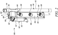
- one (first) tool 110 is securely received in the cavity 130. Additionally, another (second) tool 110' is inserted into the cavity on an opposing side of the cavity 130 seen along the central axis Y-Y'.
- the cavity 130 is configured for removably receiving two tools 110, 110' on two opposing sides of the cavity 130 seen along the central axis Y-Y'.
- the present disclosure illustrates storing of different tools 110, 110' with the tool holder 100 as illustrated in FIGS. 1-4 and a tool holder 100' as illustrated in FIG. 5 .
- the tools 110, 110' having similar parts such as handles 112, 112', grips 114, 114', extensions 116, 166' which have been simple referred to as tool(s) 110, handles 112, grips 114, and the extension 116 for ease of understanding and clarity considerations.
- the tool holders 100, 100' provide different cavities 130, 130' which have alternatively and interchangeably referred to as cavity 130 for similar clarity purposes.
- the tool holder 100 has integrated wall-mounting 140 option including one or more of a screw, nuts, and rivets.
- integrated wall mounting 140 option allows to easily mount the tool holder 100 on different installations such as a wall, a column, a post, and the like.
- the back portion 104 (indicated in FIG. 4 ) of the body 101 faces the installations when the tool holder 100 is mounted.
- the tool holder 100 includes a body 101, as illustrated in FIGS. 1 and 2 .
- the body 101 includes a front portion 102, a back portion 104 (shown in FIG. 4 ), a top portion 108, a bottom portion 109, and side portions 106.
- the front portion 102 of the body 101 includes one or more recesses 120 to receive one or more tool attachments 150 (shown in FIG.5 ).
- the one or more recesses 120 allow to store or house multiple tool attachments 150.
- the one or more tool attachments 150 may be one or more of a shovel, a rake, a plough, a hoe, a weed puller, a broom, a brush, ice scraper, a trowel, or the like.
- the tool holder 100 also allows storing of handles 112 of the tools 110 as illustrated in FIGS. 1 , 2 and 3 .
- the handles 112 may be manufactured from wood, aluminum, or other material without limiting the scope of the disclosure.
- the handles 112 may be the regular handles or the telescopic handles. Further, the handles 112 may include grips 114 for properly holding the handles 112 of the tools 110.
- the body 101 of the tool holder 100 includes at least one cavity 130 to hold the one or more tools 110.
- the tool holder 100 as illustrated in FIGS. 1-4 exhibits a pair of cavities 130 and the tool holder 100' as illustrated in FIG. 5 exhibits the single through 130'.
- actual implementation of the present disclosure may have any number, type, size, position of the cavities 130, 130' with the tool holder 100, without restricting the scope of the present disclosure.
- Each of the at least one cavity 130 defines a central axis Y-Y', and the tool holder 100 defines a longitudinal axis X-X'.
- the central axis Y-Y' is substantially perpendicular to the longitudinal axis X-X', however some embodiments may have any other angular orientation between the central axis Y-Y' and the longitudinal axis X-X' as per the application.
- the at least one cavity 130 allows to removably receive the extension 116 of the handle 112 of the one or more tools 110.
- the at least one cavity 130 receives extension 116 which is a clamping nut of the tool 110.
- the surface of the at least one cavity 130 is formed as to cooperate with the extension 116 of the handle 112.
- the at least one cavity 130 has an edge 134 allows for secure locking of the tool 110 in the tool holder 100 to prevent inadvertent or unintentional dislodging of the tool 110 from the tool holder 100.
- the tool 110' having the extension 116' may be readily made to hold with the cavity 130 of the tool holder 100, as illustrated with reference to FIGS. 1 , 2 .
- a user may simply hold or engage the tool 110' with or around the handle 112' to move or align the extension 116', as illustrated in FIG. 1 , to move the extension 116' substantially within the edge 134 of the cavity 130 as illustrated in FIG. 2 .
- at least some part of the handle 112' remains below the cavity 130' and the extension 116' at least partially engages with the edge 134 of the cavity 130, while handle 112' is being supported by one of the side portions 106 of the tool holder 100.
- the at least one cavity 130 is formed at or around the top portion 108 of the tool holder 100.
- the at least one cavity 130 at the top portion 108 of the tool holder 100 ensures that there is sufficient vertical extent of the tool holder 100 along the longitudinal axis X-X' below the at least one cavity 130. This may serve as a counter against the gravity acting on the tools 110 which hang into the tool holder 100 against the body 101 of the tool holder 100.
- the at least one cavity 130 may be formed at any length along the longitudinal axis X-X' of the tool holder 100 such that a part of the tool 110 extends along the longitudinal axis X-X' below the at least one cavity 130 and receives support from the side portion of the body 101 of the tool holder 100.
- the at least a part of the tool 110 below the at least one cavity 130 is about 2 cm, or any other suitable value depending upon factors such as size, weight, profile, type of the tool 110 or the tool holder 100.
- the part of the tool 110 which extends along the longitudinal axis X-X' below the at least one cavity 130 ensures that the tool 110 gets support from the body 101, particularly the side portions 106 of the tool holder 100. This eliminates the general tendency of the tool 110 to hang obliquely and thus allows support and proper hanging of the tool 110 substantially vertically on the tool holder 100.
- FIG. 3 illustrates the tool holder 100 having one or more recesses 120 provided at the front portion 102 of the body 101.
- the one or more recesses 120 include a plurality of equally spaced protruding surfaces 122.
- the protruding surfaces 122 may be designed to securely engage with the adapter 152 of the tool attachment 150.
- the tool holder 100 may be used to hold the one or more tools 110 by holding the extensions 116 of the handles 112 with or inside the one or more cavities 130. Further, the tool holder 100 may hold the one or more tool attachments 150 of the tools 110 with the one or more recesses 120. This provides a compact arrangement of the tool holder 100 of the present disclosure to safely, securely store the extensions 116 of the handles 112 as well as the tool attachments 150 of the tools 110.
- FIG. 4 illustrates the tool holder 100 without any of the tools 110, to highlight and appreciate the role of the cavities 130.
- the at least one cavity 130 is substantially U-shaped.
- the cavity 130 in general may be of any shape, size, type depending upon the application.
- the U-shape of the cavity 130 may be preferable to receive the extension 116 of the tools 110 with different (say circular) cross-section to properly align with U-shape of the cavity 130 of the tool holder 100.
- the at least one cavity 130 is two cavities 130 separated by a partition wall 132 as illustrated in FIGS. 1-4 .
- the partition wall 132 may be fixed (or in some cases removably coupled) along the length of the cavity 130 such as to form two cavities 130 with generally equal areas around the top portion 108 of the tool holder 100.
- the partition wall 132 may be removably received along the length of the cavity 130 by any suitable means such as glue, screws, rivets, and the like, as used or known in the art.
- the partition wall 132 may be friction fitted at any length along the cavity 130 such as to form two cavities 130 with unequal areas. This is to cater to the holding of the extensions 116 of different lengths of different tools 110.
- FIG. 5 illustrates the tool holder 100' without any of the tools 110, to highlight and appreciate the role of the cavity 130'.
- the at least one cavity 130' is circular-shaped through cavity provided around the top portion 108 of the tool holder 100'.
- the at least one cavity 130' may be one or more cavities with different sizes, types, dimensions and positions on the body 101 of the tool holder 100'.
- the through opening of the cavity 130' illustrated in present figure may allow to properly receive the extensions 116, 116' of any length, types, sizes, dimensions of the of the tools 100, 100' which are illustrated in FIGS. 1-3 . As may be seen in Fig.
- the cavity 130' is defined as a through opening, in particular a through-hole, wherein the cavity 130' is configured to removably receive two tools 110, 110' on two opposing sides of the cavity 130' seen along the central axis Y-Y' (for example shown in Fig. 2 ).
- the tool holder 100, 100' includes the side portions 106 such as to support any of the one or more tools 110, 110' with the tool holder 100, 100'. This allows vertical or sideways support of the tool(s) 110, 110' with the side portions 106 of the tool holder 100, 100', when the tool(s) 110, 110' are being supported or housed within the cavity 130, 130', respectively. Further, presence of the side portions 106 also avoids any oblique or undesired angular orientation of the tool(s) 110, 110' with respect to the tool holder 100, 100'.
- the one or more cavities 130, 130' includes circular openings.
- the circular opening of the cavity 130, 130' may be suitable to receive the extension 116, 166' with circular cross-section to allow proper alignment with the circular opening of the cavity 130, 130'.
- the cavities 130, 130' of the present disclosure may be provided with fixing means to properly secure the extensions 116, 116' of the tools 110, 110'.
- the fixing means may be a screw, button, flap, clip, and the like to allow users to secure the extensions 116, 116' of the tools 110, 110' such that to allow desired holding of the handles 112, 112' of the tools 100, 100' with the tool holders 100, 100'.
- the present disclosure provides safe, user-friendly, and efficient tool holder(s) 100, 100' for holding the one or more tool(s) 110, 110'.
- the vertical extent of the tool holders 100, 100'along the longitudinal axis X-X' and below the at least once cavities 130, 130' serves as a counter against the gravity that forces the tool(s) 110,110' hanged into the tool holder(s) 100,100' against the body 101 thereof.
- the vertical extent of the tool holder 100 may thus prevent any inadvertent or unintentional dislodging of the tool(s) 110, 110' from the tool holder(s) 100, 100'.
- the cavities 130, 130' may allow to removably receive the extension(s) 116, 116' of the handle(s) 112, 112' of the tool(s) 110, 110' and thereby obviates the need for separate, auxiliary handing accessories (say metal brackets) as used in conventional tool holders.
- the tool holder 100 may be manufactured in one-piece thereby saving the manufacturing cost and other overheads.
Landscapes
- Engineering & Computer Science (AREA)
- Mechanical Engineering (AREA)
- Workshop Equipment, Work Benches, Supports, Or Storage Means (AREA)
- Cutting Tools, Boring Holders, And Turrets (AREA)
- Gripping On Spindles (AREA)
Claims (10)
- Werkzeughalter (100, 100') zum Halten eines oder mehrerer Werkzeuge (110, 110'), umfassend:einen Körper (101), wobei der Körper (101) mindestens einen Hohlraum (130, 130') einschließt, um das eine oder die mehreren Werkzeuge (110, 110') zu halten,wobei jeder des mindestens einen Hohlraums (130, 130') eine Mittelachse (Y-Y') definiert, und der Werkzeughalter (100, 100') eine Längsachse (X-X') definiert;wobei die Mittelachse (Y-Y') im Wesentlichen senkrecht zu der Längsachse (X-X') ist, undwobei der mindestens eine Hohlraum (130, 130') konfiguriert ist, um eine Verlängerung (116, 116') eines Griffs (112, 112') des einen oder der mehreren Werkzeuge (110, 110') derart herausnehmbar aufzunehmen, dass, wenn die Verlängerung (116, 116') in dem Hohlraum (130, 130') herausnehmbar aufgenommen ist, mindestens ein Teil des Werkzeugs (110, 110') sich entlang der Längsachse (X-X') unterhalb des mindestens einen Hohlraums (130, 130') verlängert;dadurch gekennzeichnet, dass:
der Hohlraum (130, 130') als eine Durchgangsöffnung definiert ist, und wobei der Hohlraum (130, 130') konfiguriert ist, um gleichzeitig zwei Werkzeuge (110, 110') auf zwei gegenüberliegenden Seiten des Hohlraums (130, 130'), entlang der Mittelachse (Y-Y') betrachtet, aufzunehmen. - Werkzeughalter (100, 100') nach Anspruch1, wobei der mindestens eine Teil des Werkzeugs (110, 110') unterhalb des mindestens einen Hohlraums (130, 130') etwa 2 cm beträgt.
- Werkzeughalter (100, 100') nach einem der vorstehenden Ansprüche, wobei die Oberfläche des mindestens einen Hohlraums (130, 130') ausgebildet ist, um mit der Verlängerung (116, 116') des Griffs (112, 112') zusammenzuwirken.
- Werkzeughalter (100, 100') nach einem der vorstehenden Ansprüche, wobei der mindestens eine Hohlraum (130, 130') um einen oberen Teil des Werkzeughalters (100, 100') herum ausgebildet ist.
- Werkzeughalter (100') nach einem der Ansprüche 1 bis 4, wobei der eine oder die mehreren Hohlräume (130') kreisförmige Öffnungen einschließen.
- Werkzeughalter (100, 100') nach einem der vorstehenden Ansprüche, wobei der Werkzeughalter (100) ferner eine oder mehrere Aussparungen (120) definiert, um einen oder mehrere Werkzeugaufsätze (150) aufzunehmen.
- Werkzeughalter (100, 100') nach einem der vorstehenden Ansprüche, wobei der Werkzeughalter (100, 100') Seitenabschnitte (106) einschließt, wie um ein beliebiges des einen oder der mehreren Werkzeuge (110,110') mit dem Werkzeughalter (100) zu stützen.
- Werkzeughalter (100, 100') nach einem der vorstehenden Ansprüche, wobei der Werkzeughalter (100, 100') eine integrierte Wandbefestigungs(140)-Option aufweist, einschließlich eines oder mehreren von einer Schraube, Muttern und Nieten.
- Verwendung des Werkzeughalters (100, 100') nach einem der vorstehenden Ansprüche, wobei der mindestens eine Hohlraum (130) verwendet wird, um die Verlängerung (116, 116') aufzunehmen, die eine Klemmmutter des Werkzeugs (110, 110') ist.
- Verwendung des Werkzeughalters (100, 100') nach einem der Ansprüche 1 bis 8, um das eine oder die mehreren Werkzeuge (110, 110') zu befestigen.
Applications Claiming Priority (2)
| Application Number | Priority Date | Filing Date | Title |
|---|---|---|---|
| EP21192072 | 2021-08-19 | ||
| PCT/EP2022/072647 WO2023020956A1 (en) | 2021-08-19 | 2022-08-12 | Tool holder |
Publications (2)
| Publication Number | Publication Date |
|---|---|
| EP4157588A1 EP4157588A1 (de) | 2023-04-05 |
| EP4157588B1 true EP4157588B1 (de) | 2024-05-01 |
Family
ID=77518929
Family Applications (2)
| Application Number | Title | Priority Date | Filing Date |
|---|---|---|---|
| EP22710091.4A Active EP4157587B1 (de) | 2021-08-19 | 2022-03-03 | Werkzeughalter |
| EP22762100.0A Active EP4157588B1 (de) | 2021-08-19 | 2022-08-12 | Werkzeughalter |
Family Applications Before (1)
| Application Number | Title | Priority Date | Filing Date |
|---|---|---|---|
| EP22710091.4A Active EP4157587B1 (de) | 2021-08-19 | 2022-03-03 | Werkzeughalter |
Country Status (5)
| Country | Link |
|---|---|
| EP (2) | EP4157587B1 (de) |
| CN (2) | CN115996819B (de) |
| FI (1) | FI4157588T3 (de) |
| PL (1) | PL4157588T3 (de) |
| WO (2) | WO2023020718A1 (de) |
Family Cites Families (14)
| Publication number | Priority date | Publication date | Assignee | Title |
|---|---|---|---|---|
| US6719153B2 (en) * | 1998-04-27 | 2004-04-13 | William R. Heneveld | Storage rack for elongated items |
| CA2280458C (en) * | 1998-08-14 | 2006-07-25 | Maxtech Manufacturing Inc. | Holder with shaft security mechanism for screwdrivers or the like |
| GB2387529A (en) * | 2002-04-17 | 2003-10-22 | Sen-Chou Chen | Seat for receiving wood working tools |
| AU2003101042B4 (en) * | 2003-12-23 | 2004-06-10 | Global Industries Holdings Limited | Garden tool rack |
| TWM251447U (en) * | 2004-02-19 | 2004-12-01 | Global Ind Holdings Ltd | Gardening tools base with stationary barrier |
| TWI263571B (en) * | 2004-10-26 | 2006-10-11 | Global Ind Holdings Ltd | Hand tool storage stand |
| CN2745709Y (zh) * | 2004-11-01 | 2005-12-14 | 巴哈马全球工业控股公司 | 手工具置纳座 |
| EP2186489B1 (de) * | 2008-11-12 | 2013-03-13 | Elekta AB (publ) | Einzelschrauben-Doppelachsensperrmechanismus |
| CN201950659U (zh) * | 2010-12-23 | 2011-08-31 | 上海齐迈五金有限公司 | 一种多功能架子盒 |
| CN203919010U (zh) * | 2014-05-06 | 2014-11-05 | 宁波市鄞州永佳电机工具有限公司 | 一种便携螺丝刀工具盒 |
| TWI617238B (zh) * | 2015-03-06 | 2018-03-11 | 園藝工具快拆裝置 | |
| CN206690061U (zh) * | 2017-05-22 | 2017-12-01 | 厦门德力实自动化设备有限公司 | 一种气轴挂架 |
| US10357106B1 (en) * | 2017-10-26 | 2019-07-23 | Lawrence Lee | Rack for various items |
| DE202017106619U1 (de) * | 2017-11-01 | 2018-01-08 | Maik Haase | Ablagevorrichtung für ein Arbeitsgerüst |
-
2022
- 2022-03-03 EP EP22710091.4A patent/EP4157587B1/de active Active
- 2022-03-03 WO PCT/EP2022/055481 patent/WO2023020718A1/en not_active Ceased
- 2022-03-03 CN CN202280005217.4A patent/CN115996819B/zh active Active
- 2022-08-12 FI FIEP22762100.0T patent/FI4157588T3/fi active
- 2022-08-12 EP EP22762100.0A patent/EP4157588B1/de active Active
- 2022-08-12 CN CN202280005410.8A patent/CN115996820B/zh active Active
- 2022-08-12 PL PL22762100.0T patent/PL4157588T3/pl unknown
- 2022-08-12 WO PCT/EP2022/072647 patent/WO2023020956A1/en not_active Ceased
Also Published As
| Publication number | Publication date |
|---|---|
| EP4157587A1 (de) | 2023-04-05 |
| WO2023020718A1 (en) | 2023-02-23 |
| WO2023020956A1 (en) | 2023-02-23 |
| CN115996820B (zh) | 2023-08-15 |
| FI4157588T3 (fi) | 2024-05-29 |
| EP4157587B1 (de) | 2024-04-10 |
| PL4157588T3 (pl) | 2024-07-01 |
| CN115996820A (zh) | 2023-04-21 |
| CN115996819A (zh) | 2023-04-21 |
| CN115996819B (zh) | 2023-09-26 |
| EP4157588A1 (de) | 2023-04-05 |
Similar Documents
| Publication | Publication Date | Title |
|---|---|---|
| US7967264B1 (en) | Ladder attached support bracket and paint can and roller pan holders for use therewith | |
| US4467925A (en) | Wheelbarrow and garden tool storage rack | |
| US6041947A (en) | Storage rack for elongated items | |
| US6626402B1 (en) | Cleaning tool holder | |
| US7546990B1 (en) | Tool hanger system kit | |
| US6260865B1 (en) | Tool holder | |
| US5957238A (en) | Tool tray for ladders | |
| US6412601B1 (en) | Ladder pan | |
| US6719153B2 (en) | Storage rack for elongated items | |
| CA2367632C (en) | Funnel system for holding implements | |
| FR2955276A1 (fr) | Assemblage de porte-outil | |
| US4765584A (en) | Tool holder for water pipe | |
| EP4157588B1 (de) | Werkzeughalter | |
| US5868374A (en) | Push broom stand | |
| US20080029981A1 (en) | Janitorial cleaning cart | |
| US20170188735A1 (en) | Articulating Stand for Brooms and Similarly Handled Implements | |
| EP4238457B1 (de) | Werkzeughalter | |
| EP4238705A1 (de) | Werkzeughalter | |
| US7040493B2 (en) | Garden tool rack | |
| JPH08140871A (ja) | 流し台用網籠 | |
| CA2278954A1 (en) | Handle assembly for manual tool | |
| EP4203662B1 (de) | Werkzeugaufbewahrungsmittel | |
| EP4119479A1 (de) | Mobile schlauchrollenanordnung | |
| WO2005095065A1 (en) | Rack for holding tools and other implements | |
| AU2003101042A4 (en) | Garden tool rack |
Legal Events
| Date | Code | Title | Description |
|---|---|---|---|
| STAA | Information on the status of an ep patent application or granted ep patent |
Free format text: STATUS: UNKNOWN |
|
| STAA | Information on the status of an ep patent application or granted ep patent |
Free format text: STATUS: THE INTERNATIONAL PUBLICATION HAS BEEN MADE |
|
| PUAI | Public reference made under article 153(3) epc to a published international application that has entered the european phase |
Free format text: ORIGINAL CODE: 0009012 |
|
| STAA | Information on the status of an ep patent application or granted ep patent |
Free format text: STATUS: REQUEST FOR EXAMINATION WAS MADE |
|
| 17P | Request for examination filed |
Effective date: 20221201 |
|
| AK | Designated contracting states |
Kind code of ref document: A1 Designated state(s): AL AT BE BG CH CY CZ DE DK EE ES FI FR GB GR HR HU IE IS IT LI LT LU LV MC MK MT NL NO PL PT RO RS SE SI SK SM TR |
|
| GRAP | Despatch of communication of intention to grant a patent |
Free format text: ORIGINAL CODE: EPIDOSNIGR1 |
|
| STAA | Information on the status of an ep patent application or granted ep patent |
Free format text: STATUS: GRANT OF PATENT IS INTENDED |
|
| INTG | Intention to grant announced |
Effective date: 20240116 |
|
| GRAS | Grant fee paid |
Free format text: ORIGINAL CODE: EPIDOSNIGR3 |
|
| P01 | Opt-out of the competence of the unified patent court (upc) registered |
Effective date: 20240206 |
|
| GRAA | (expected) grant |
Free format text: ORIGINAL CODE: 0009210 |
|
| STAA | Information on the status of an ep patent application or granted ep patent |
Free format text: STATUS: THE PATENT HAS BEEN GRANTED |
|
| AK | Designated contracting states |
Kind code of ref document: B1 Designated state(s): AL AT BE BG CH CY CZ DE DK EE ES FI FR GB GR HR HU IE IS IT LI LT LU LV MC MK MT NL NO PL PT RO RS SE SI SK SM TR |
|
| DAV | Request for validation of the european patent (deleted) | ||
| DAX | Request for extension of the european patent (deleted) | ||
| REG | Reference to a national code |
Ref country code: GB Ref legal event code: FG4D |
|
| REG | Reference to a national code |
Ref country code: CH Ref legal event code: EP |
|
| REG | Reference to a national code |
Ref country code: DE Ref legal event code: R096 Ref document number: 602022003250 Country of ref document: DE |
|
| REG | Reference to a national code |
Ref country code: IE Ref legal event code: FG4D |
|
| REG | Reference to a national code |
Ref country code: FI Ref legal event code: FGE |
|
| REG | Reference to a national code |
Ref country code: LT Ref legal event code: MG9D |
|
| REG | Reference to a national code |
Ref country code: NL Ref legal event code: MP Effective date: 20240501 |
|
| PG25 | Lapsed in a contracting state [announced via postgrant information from national office to epo] |
Ref country code: IS Free format text: LAPSE BECAUSE OF FAILURE TO SUBMIT A TRANSLATION OF THE DESCRIPTION OR TO PAY THE FEE WITHIN THE PRESCRIBED TIME-LIMIT Effective date: 20240901 |
|
| PG25 | Lapsed in a contracting state [announced via postgrant information from national office to epo] |
Ref country code: BG Free format text: LAPSE BECAUSE OF FAILURE TO SUBMIT A TRANSLATION OF THE DESCRIPTION OR TO PAY THE FEE WITHIN THE PRESCRIBED TIME-LIMIT Effective date: 20240501 |
|
| PG25 | Lapsed in a contracting state [announced via postgrant information from national office to epo] |
Ref country code: HR Free format text: LAPSE BECAUSE OF FAILURE TO SUBMIT A TRANSLATION OF THE DESCRIPTION OR TO PAY THE FEE WITHIN THE PRESCRIBED TIME-LIMIT Effective date: 20240501 |
|
| PG25 | Lapsed in a contracting state [announced via postgrant information from national office to epo] |
Ref country code: GR Free format text: LAPSE BECAUSE OF FAILURE TO SUBMIT A TRANSLATION OF THE DESCRIPTION OR TO PAY THE FEE WITHIN THE PRESCRIBED TIME-LIMIT Effective date: 20240802 |
|
| PG25 | Lapsed in a contracting state [announced via postgrant information from national office to epo] |
Ref country code: PT Free format text: LAPSE BECAUSE OF FAILURE TO SUBMIT A TRANSLATION OF THE DESCRIPTION OR TO PAY THE FEE WITHIN THE PRESCRIBED TIME-LIMIT Effective date: 20240902 |
|
| REG | Reference to a national code |
Ref country code: AT Ref legal event code: MK05 Ref document number: 1681719 Country of ref document: AT Kind code of ref document: T Effective date: 20240501 |
|
| PG25 | Lapsed in a contracting state [announced via postgrant information from national office to epo] |
Ref country code: NL Free format text: LAPSE BECAUSE OF FAILURE TO SUBMIT A TRANSLATION OF THE DESCRIPTION OR TO PAY THE FEE WITHIN THE PRESCRIBED TIME-LIMIT Effective date: 20240501 |
|
| PG25 | Lapsed in a contracting state [announced via postgrant information from national office to epo] |
Ref country code: ES Free format text: LAPSE BECAUSE OF FAILURE TO SUBMIT A TRANSLATION OF THE DESCRIPTION OR TO PAY THE FEE WITHIN THE PRESCRIBED TIME-LIMIT Effective date: 20240501 |
|
| PG25 | Lapsed in a contracting state [announced via postgrant information from national office to epo] |
Ref country code: AT Free format text: LAPSE BECAUSE OF FAILURE TO SUBMIT A TRANSLATION OF THE DESCRIPTION OR TO PAY THE FEE WITHIN THE PRESCRIBED TIME-LIMIT Effective date: 20240501 |
|
| PG25 | Lapsed in a contracting state [announced via postgrant information from national office to epo] |
Ref country code: LV Free format text: LAPSE BECAUSE OF FAILURE TO SUBMIT A TRANSLATION OF THE DESCRIPTION OR TO PAY THE FEE WITHIN THE PRESCRIBED TIME-LIMIT Effective date: 20240501 |
|
| PG25 | Lapsed in a contracting state [announced via postgrant information from national office to epo] |
Ref country code: PT Free format text: LAPSE BECAUSE OF FAILURE TO SUBMIT A TRANSLATION OF THE DESCRIPTION OR TO PAY THE FEE WITHIN THE PRESCRIBED TIME-LIMIT Effective date: 20240902 Ref country code: NO Free format text: LAPSE BECAUSE OF FAILURE TO SUBMIT A TRANSLATION OF THE DESCRIPTION OR TO PAY THE FEE WITHIN THE PRESCRIBED TIME-LIMIT Effective date: 20240801 Ref country code: NL Free format text: LAPSE BECAUSE OF FAILURE TO SUBMIT A TRANSLATION OF THE DESCRIPTION OR TO PAY THE FEE WITHIN THE PRESCRIBED TIME-LIMIT Effective date: 20240501 Ref country code: LV Free format text: LAPSE BECAUSE OF FAILURE TO SUBMIT A TRANSLATION OF THE DESCRIPTION OR TO PAY THE FEE WITHIN THE PRESCRIBED TIME-LIMIT Effective date: 20240501 Ref country code: IS Free format text: LAPSE BECAUSE OF FAILURE TO SUBMIT A TRANSLATION OF THE DESCRIPTION OR TO PAY THE FEE WITHIN THE PRESCRIBED TIME-LIMIT Effective date: 20240901 Ref country code: HR Free format text: LAPSE BECAUSE OF FAILURE TO SUBMIT A TRANSLATION OF THE DESCRIPTION OR TO PAY THE FEE WITHIN THE PRESCRIBED TIME-LIMIT Effective date: 20240501 Ref country code: GR Free format text: LAPSE BECAUSE OF FAILURE TO SUBMIT A TRANSLATION OF THE DESCRIPTION OR TO PAY THE FEE WITHIN THE PRESCRIBED TIME-LIMIT Effective date: 20240802 Ref country code: ES Free format text: LAPSE BECAUSE OF FAILURE TO SUBMIT A TRANSLATION OF THE DESCRIPTION OR TO PAY THE FEE WITHIN THE PRESCRIBED TIME-LIMIT Effective date: 20240501 Ref country code: BG Free format text: LAPSE BECAUSE OF FAILURE TO SUBMIT A TRANSLATION OF THE DESCRIPTION OR TO PAY THE FEE WITHIN THE PRESCRIBED TIME-LIMIT Effective date: 20240501 Ref country code: AT Free format text: LAPSE BECAUSE OF FAILURE TO SUBMIT A TRANSLATION OF THE DESCRIPTION OR TO PAY THE FEE WITHIN THE PRESCRIBED TIME-LIMIT Effective date: 20240501 Ref country code: RS Free format text: LAPSE BECAUSE OF FAILURE TO SUBMIT A TRANSLATION OF THE DESCRIPTION OR TO PAY THE FEE WITHIN THE PRESCRIBED TIME-LIMIT Effective date: 20240801 |
|
| PG25 | Lapsed in a contracting state [announced via postgrant information from national office to epo] |
Ref country code: DK Free format text: LAPSE BECAUSE OF FAILURE TO SUBMIT A TRANSLATION OF THE DESCRIPTION OR TO PAY THE FEE WITHIN THE PRESCRIBED TIME-LIMIT Effective date: 20240501 |
|
| PG25 | Lapsed in a contracting state [announced via postgrant information from national office to epo] |
Ref country code: EE Free format text: LAPSE BECAUSE OF FAILURE TO SUBMIT A TRANSLATION OF THE DESCRIPTION OR TO PAY THE FEE WITHIN THE PRESCRIBED TIME-LIMIT Effective date: 20240501 |
|
| PG25 | Lapsed in a contracting state [announced via postgrant information from national office to epo] |
Ref country code: CZ Free format text: LAPSE BECAUSE OF FAILURE TO SUBMIT A TRANSLATION OF THE DESCRIPTION OR TO PAY THE FEE WITHIN THE PRESCRIBED TIME-LIMIT Effective date: 20240501 |
|
| PG25 | Lapsed in a contracting state [announced via postgrant information from national office to epo] |
Ref country code: SK Free format text: LAPSE BECAUSE OF FAILURE TO SUBMIT A TRANSLATION OF THE DESCRIPTION OR TO PAY THE FEE WITHIN THE PRESCRIBED TIME-LIMIT Effective date: 20240501 Ref country code: RO Free format text: LAPSE BECAUSE OF FAILURE TO SUBMIT A TRANSLATION OF THE DESCRIPTION OR TO PAY THE FEE WITHIN THE PRESCRIBED TIME-LIMIT Effective date: 20240501 |
|
| PG25 | Lapsed in a contracting state [announced via postgrant information from national office to epo] |
Ref country code: SM Free format text: LAPSE BECAUSE OF FAILURE TO SUBMIT A TRANSLATION OF THE DESCRIPTION OR TO PAY THE FEE WITHIN THE PRESCRIBED TIME-LIMIT Effective date: 20240501 |
|
| PG25 | Lapsed in a contracting state [announced via postgrant information from national office to epo] |
Ref country code: SM Free format text: LAPSE BECAUSE OF FAILURE TO SUBMIT A TRANSLATION OF THE DESCRIPTION OR TO PAY THE FEE WITHIN THE PRESCRIBED TIME-LIMIT Effective date: 20240501 Ref country code: SK Free format text: LAPSE BECAUSE OF FAILURE TO SUBMIT A TRANSLATION OF THE DESCRIPTION OR TO PAY THE FEE WITHIN THE PRESCRIBED TIME-LIMIT Effective date: 20240501 Ref country code: RO Free format text: LAPSE BECAUSE OF FAILURE TO SUBMIT A TRANSLATION OF THE DESCRIPTION OR TO PAY THE FEE WITHIN THE PRESCRIBED TIME-LIMIT Effective date: 20240501 Ref country code: EE Free format text: LAPSE BECAUSE OF FAILURE TO SUBMIT A TRANSLATION OF THE DESCRIPTION OR TO PAY THE FEE WITHIN THE PRESCRIBED TIME-LIMIT Effective date: 20240501 Ref country code: DK Free format text: LAPSE BECAUSE OF FAILURE TO SUBMIT A TRANSLATION OF THE DESCRIPTION OR TO PAY THE FEE WITHIN THE PRESCRIBED TIME-LIMIT Effective date: 20240501 Ref country code: CZ Free format text: LAPSE BECAUSE OF FAILURE TO SUBMIT A TRANSLATION OF THE DESCRIPTION OR TO PAY THE FEE WITHIN THE PRESCRIBED TIME-LIMIT Effective date: 20240501 |
|
| REG | Reference to a national code |
Ref country code: DE Ref legal event code: R097 Ref document number: 602022003250 Country of ref document: DE |
|
| PG25 | Lapsed in a contracting state [announced via postgrant information from national office to epo] |
Ref country code: IT Free format text: LAPSE BECAUSE OF FAILURE TO SUBMIT A TRANSLATION OF THE DESCRIPTION OR TO PAY THE FEE WITHIN THE PRESCRIBED TIME-LIMIT Effective date: 20240501 |
|
| PLBE | No opposition filed within time limit |
Free format text: ORIGINAL CODE: 0009261 |
|
| STAA | Information on the status of an ep patent application or granted ep patent |
Free format text: STATUS: NO OPPOSITION FILED WITHIN TIME LIMIT |
|
| 26N | No opposition filed |
Effective date: 20250204 |
|
| PG25 | Lapsed in a contracting state [announced via postgrant information from national office to epo] |
Ref country code: LU Free format text: LAPSE BECAUSE OF NON-PAYMENT OF DUE FEES Effective date: 20240812 |
|
| PG25 | Lapsed in a contracting state [announced via postgrant information from national office to epo] |
Ref country code: SI Free format text: LAPSE BECAUSE OF FAILURE TO SUBMIT A TRANSLATION OF THE DESCRIPTION OR TO PAY THE FEE WITHIN THE PRESCRIBED TIME-LIMIT Effective date: 20240501 Ref country code: MC Free format text: LAPSE BECAUSE OF FAILURE TO SUBMIT A TRANSLATION OF THE DESCRIPTION OR TO PAY THE FEE WITHIN THE PRESCRIBED TIME-LIMIT Effective date: 20240501 |
|
| REG | Reference to a national code |
Ref country code: BE Ref legal event code: MM Effective date: 20240831 |
|
| PGFP | Annual fee paid to national office [announced via postgrant information from national office to epo] |
Ref country code: PL Payment date: 20250620 Year of fee payment: 4 |
|
| PG25 | Lapsed in a contracting state [announced via postgrant information from national office to epo] |
Ref country code: BE Free format text: LAPSE BECAUSE OF NON-PAYMENT OF DUE FEES Effective date: 20240831 |
|
| PG25 | Lapsed in a contracting state [announced via postgrant information from national office to epo] |
Ref country code: IE Free format text: LAPSE BECAUSE OF NON-PAYMENT OF DUE FEES Effective date: 20240812 |
|
| PG25 | Lapsed in a contracting state [announced via postgrant information from national office to epo] |
Ref country code: SE Free format text: LAPSE BECAUSE OF FAILURE TO SUBMIT A TRANSLATION OF THE DESCRIPTION OR TO PAY THE FEE WITHIN THE PRESCRIBED TIME-LIMIT Effective date: 20240501 |
|
| PGFP | Annual fee paid to national office [announced via postgrant information from national office to epo] |
Ref country code: FI Payment date: 20250709 Year of fee payment: 4 |
|
| PGFP | Annual fee paid to national office [announced via postgrant information from national office to epo] |
Ref country code: DE Payment date: 20250708 Year of fee payment: 4 |
|
| PGFP | Annual fee paid to national office [announced via postgrant information from national office to epo] |
Ref country code: FR Payment date: 20250707 Year of fee payment: 4 |
|
| PG25 | Lapsed in a contracting state [announced via postgrant information from national office to epo] |
Ref country code: CY Free format text: LAPSE BECAUSE OF FAILURE TO SUBMIT A TRANSLATION OF THE DESCRIPTION OR TO PAY THE FEE WITHIN THE PRESCRIBED TIME-LIMIT; INVALID AB INITIO Effective date: 20220812 |