EP4156895B1 - Steuerung der höhe eines mähdrescherschneidwerks - Google Patents
Steuerung der höhe eines mähdrescherschneidwerks Download PDFInfo
- Publication number
- EP4156895B1 EP4156895B1 EP21737234.1A EP21737234A EP4156895B1 EP 4156895 B1 EP4156895 B1 EP 4156895B1 EP 21737234 A EP21737234 A EP 21737234A EP 4156895 B1 EP4156895 B1 EP 4156895B1
- Authority
- EP
- European Patent Office
- Prior art keywords
- sensor
- ground
- header
- output
- combine
- Prior art date
- Legal status (The legal status is an assumption and is not a legal conclusion. Google has not performed a legal analysis and makes no representation as to the accuracy of the status listed.)
- Active
Links
Images


Classifications
-
- A—HUMAN NECESSITIES
- A01—AGRICULTURE; FORESTRY; ANIMAL HUSBANDRY; HUNTING; TRAPPING; FISHING
- A01D—HARVESTING; MOWING
- A01D41/00—Combines, i.e. harvesters or mowers combined with threshing devices
- A01D41/12—Details of combines
- A01D41/14—Mowing tables
- A01D41/141—Automatic header control
-
- A—HUMAN NECESSITIES
- A01—AGRICULTURE; FORESTRY; ANIMAL HUSBANDRY; HUNTING; TRAPPING; FISHING
- A01D—HARVESTING; MOWING
- A01D41/00—Combines, i.e. harvesters or mowers combined with threshing devices
- A01D41/12—Details of combines
- A01D41/14—Mowing tables
- A01D41/145—Header lifting devices
-
- A—HUMAN NECESSITIES
- A01—AGRICULTURE; FORESTRY; ANIMAL HUSBANDRY; HUNTING; TRAPPING; FISHING
- A01D—HARVESTING; MOWING
- A01D34/00—Mowers; Mowing apparatus of harvesters
- A01D34/006—Control or measuring arrangements
- A01D34/008—Control or measuring arrangements for automated or remotely controlled operation
-
- A—HUMAN NECESSITIES
- A01—AGRICULTURE; FORESTRY; ANIMAL HUSBANDRY; HUNTING; TRAPPING; FISHING
- A01D—HARVESTING; MOWING
- A01D34/00—Mowers; Mowing apparatus of harvesters
- A01D34/01—Mowers; Mowing apparatus of harvesters characterised by features relating to the type of cutting apparatus
- A01D34/02—Mowers; Mowing apparatus of harvesters characterised by features relating to the type of cutting apparatus having reciprocating cutters
- A01D34/28—Adjusting devices for the cutter-bar
- A01D34/283—Adjustment of the cutter bar in a vertical plane, i.e. to adjust the angle between the cutter bar and the soil
Definitions
- the forward-looking sensors may detect contour changes too far in advance and cause the header to move upward (or downward) prematurely, thereby resulting in sub-optimal harvesting.
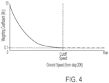
- the cutoff speed is identified on the graph in FIG. 4 .
- the cutoff speed is the speed of the combine at which the function plotted on the graph transitions from a decaying value to a substantially constant value.
- the cutoff speed may be 5 miles per hour, for example.
- the weighting coefficient W1 is 0.1. The purpose of the weighting coefficient W1 will be described in greater detail with reference to step 214.
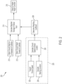
- the Output will vary depending upon the signals transmitted by the sensors 26 and 30, the detected ground speed of the combine 10 transmitted by sensor 17, as well as the detected steering curvature and the lateral location of the sensor pair 26/30 on the header 12 (as will be described with reference to FIG. 3 ).
- controller 50 will receive an Output at step 216 for every sensor pair 26/30, which may include, for example, four different sensor pairs A-D, as shown in FIG. 5A .
- the controller 50 will then control the motor 29 and actuator 31 to raise, lower, and/or tilt the header 12 depending upon the output calculated at step 216 for every sensor pair 26/30 of the header 12.
- step 206 the controller 50 calculates the local ground speed for the sensor pair 26/30.
- the local ground speed for the sensor pair 26/30 which compensates for the turning radius of the combine 10, equals the product of the Gain that is calculated at step 312 and the machine ground speed that is calculated at step 202.
- the process 205 is then complete for that sensor pair 26/30, and the method moves along to step 208, as was described with reference to FIG. 2 .
- process 205 along with the other steps of method 200, are performed for each sensor pair 26/30.
- software code or “code” used herein refers to any instructions or set of instructions that influence the operation of a computer or controller. They may exist in a computer-executable form, such as machine code, which is the set of instructions and data directly executed by a computer's central processing unit or by a controller, a human-understandable form, such as source code, which may be compiled in order to be executed by a computer's central processing unit or by a controller, or an intermediate form, such as object code, which is produced by a compiler.
- the term "software code” or “code” also includes any human-understandable computer instructions or set of instructions, e.g., a script, that may be executed on the fly with the aid of an interpreter executed by a computer's central processing unit or by a controller.
Landscapes
- Life Sciences & Earth Sciences (AREA)
- Environmental Sciences (AREA)
- Harvester Elements (AREA)
- Guiding Agricultural Machines (AREA)
- Combines (AREA)
Claims (20)
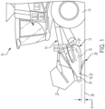
- Mähdrescher (10) mit:einem Erntevorsatz (12) zum Ernten von Erntegut von dem Boden;einem Bodengeschwindigkeitssensor (17), der dazu eingerichtet ist, eine Bodengeschwindigkeit des Mähdreschers zu erfassen;einem Bodenhöhensensor (26), der dazu eingerichtet ist, eine Kontur des Bodens zu erfassen, die sich direkt unter dem Erntevorsatz (12) befindet;einem nach vorne blickenden Sensor (FLS) (30), der dazu eingerichtet ist, eine Kontur des Bodens zu erfassen, die sich vor dem Erntevorsatz (12) befindet; undwobei der Mähdrescher des Weiteren eine Steuereinheit (50) aufweist, die dazu eingerichtet ist, Signale von dem Bodengeschwindigkeitssensor (17), dem Bodenhöhensensor (26) und dem nach vorne blickenden Sensor (30) zu empfangen,dadurch gekennzeichnet, dass die Steuereinheit des Weiteren dazu eingerichtet ist, eine Erntevorsatzhöhenausgabe in Abhängigkeit von (i) einer Ausgabe des Bodengeschwindigkeitssensors (17), die eine Bodengeschwindigkeit des Mähdreschers darstellt, (ii) einer Ausgabe des Bodenhöhensensors (26), die die Kontur des Bodens darstellt, die sich direkt unter dem Erntevorsatz (12) befindet, und (iii) einer Ausgabe des nach vorne blickenden Sensors (30), die die Kontur des Bodens darstellt, die sich vor dem Erntevorsatz (12) befindet, zu berechnen,wobei die Steuereinheit (50) des Weiteren dazu eingerichtet ist, die Ausgaben des Bodengeschwindigkeitssensors (17) und des nach vorne blickenden Sensors (30) in Abhängigkeit von der Geschwindigkeit des Mähdreschers beim Berechnen der Erntevorsatzhöhenausgabe zu gewichten.
- Mähdrescher nach Anspruch 1, wobei der Mähdrescher des Weiteren einen Motor (29) oder eine Betätigungseinrichtung zum wahlweisen Anheben oder Absenken des Erntevorsatzes (12) aufweist, wobei die Steuereinheit (50) dazu eingerichtet ist, den Motor (29) zum wahlweisen Anheben oder Absenken des Erntevorsatzes (12) basierend auf der Erntevorsatzhöhenausgabe zu betätigen.
- Mähdrescher nach einem der vorhergehenden Ansprüche, wobei der Erntevorsatz (12) einen Messerbalken (18) umfasst, wobei der Bodenhöhensensor (26) dazu eingerichtet ist, die Kontur des Bodens zu erfassen, die sich direkt unter dem Messerbalken (18) befindet, und wobei der nach vorne blickende Sensor (30) dazu eingerichtet ist, die Kontur des Bodens zu erfassen, die sich vor dem Erntevorsatz (12) befindet.
- Mähdrescher nach einem der vorhergehenden Ansprüche, wobei bei einer ersten Bodengeschwindigkeit des Mähdreschers die Steuereinheit (50) dazu eingerichtet ist, die Ausgabe des nach vorne blickenden Sensors (30) höher als die Ausgabe des Bodenhöhensensors (26) beim Berechnen der Erntevorsatzhöhenausgabe zu gewichten, und bei einer zweiten Bodengeschwindigkeit des Mähdreschers, die niedriger als die erste Bodengeschwindigkeit ist, die Steuereinheit (50) dazu eingerichtet ist, die Ausgabe des Bodengeschwindigkeitssensors (26) höher als die Ausgabe des nach vorne blickenden Sensors (30) beim Berechnen der Erntevorsatzhöhenausgabe zu gewichten.
- Mähdrescher nach einem der vorhergehenden Ansprüche, wobei der nach vorne blickende Sensor (30) und der Bodenhöhensensor (26) ein Sensorpaar (26/30) ausbilden, und wobei das Sensorpaar (26/30) an derselben lateralen Stelle an dem Erntevorsatz (12) angeordnet ist.
- Mähdrescher nach Anspruch 5, wobei der Mähdrescher des Weiteren eine Mehrzahl an Sensorpaaren (26/30) aufweist, wobei die Sensorpaare (26/30) entlang einer lateralen Länge des Erntevorsatzes (12) voneinander beabstandet sind.
- Mähdrescher nach Anspruch 6, wobei die Steuereinheit (50) des Weiteren dazu eingerichtet ist, eine Erntevorsatzhöhenausgabe für jedes Sensorpaar (26/30) zu berechnen.
- Mähdrescher nach Anspruch 7, wobei der Mähdrescher des Weiteren eine Betätigungseinrichtung (31) zum Neigen des Erntevorsatzes (12) aufweist, und wobei die Steuereinheit (50) des Weiteren dazu eingerichtet ist, die Betätigungseinrichtung basierend auf der Erntevorsatzhöhenausgabe für jedes Sensorpaar (26/30) zu steuern.
- Mähdrescher nach Anspruch 7, dadurch gekennzeichnet, dass für jedes Sensorpaar (26/30) die Steuereinheit (50) dazu eingerichtet ist, die Ausgabe des Bodengeschwindigkeitssensors (17) in Abhängigkeit von (i) einem Wenderadius des Mähdreschers (10), und (ii) einer lateralen Position des Sensorpaars (26/30) entlang einer Länge des Erntevorsatzes (12) zu modifizieren.
- Mähdrescher nach einem der vorhergehenden Ansprüche, dadurch gekennzeichnet, dass beim Gewichten der Ausgaben des Bodenhöhensensors (26) und des nach vorne blickenden Sensors (30) die Steuereinheit (50) dazu eingerichtet ist, entweder eine Funktion oder eine Umsetzungstabelle zu verwenden, die unterschiedliche Gewichtungskoeffizienten für unterschiedliche Bodengeschwindigkeiten des Mähdreschers bereitstellt.
- Mähdrescher nach einem der vorhergehenden Ansprüche, wobei die Steuereinheit (50) dazu eingerichtet ist, die Erntevorsatzhöhenausgabe basierend auf der folgenden Formel zu berechnen:
 die Eingabe, die Ausgabe des Bodenhöhensensors (26) ist;die Eingabe2 die Ausgabe des nach vorne blickenden Sensors (30) ist;W1 ein Gewichtungskoeffizient ist, der in Abhängigkeit von der Bodengeschwindigkeit ist; unddie Ausgabe die Erntevorsatzhöhenausgabe ist.
 - Mähdrescher nach einem der vorhergehenden Ansprüche, wobei der Bodenhöhensensor (26) dazu eingerichtet ist, den Boden direkt zu kontaktieren und der nach vorne blickende Sensor (30) nicht dazu eingerichtet ist, den Boden zu kontaktieren.
- Verfahren zum Steuern einer Höhe eines Erntevorsatzes (12) eines Mähdreschers, wobei der Mähdrescher einen Bodengeschwindigkeitssensor (17), der dazu eingerichtet ist, eine Bodengeschwindigkeit des Mähdreschers zu erfassen, einen Bodenhöhensensor (26), der dazu eingerichtet ist, eine Kontur des Bodens zu erfassen, die sich direkt unter dem Erntevorsatz (12) befindet, und einen nach vorne blickenden Sensor (FLS) (30) aufweist, der dazu eingerichtet ist, eine Kontur des Bodens zu erfassen, die sich vor dem Erntevorsatz (12) befindet, wobei das Verfahren die Schritte aufweist:
Empfangen von Signalen in einer Steuereinheit (50) des Erntevorsatzes (12) oder des Mähdreschers von dem Bodengeschwindigkeitssensor (17), dem Bodenhöhensensor (26) und dem nach vorne blickenden Sensor (30), dadurch gekennzeichnet, dass das Verfahren des Weiten folgende Schritte aufweist:Berechnen einer Erntevorsatzhöhenausgabe unter Verwendung der Steuereinheit (50) in Abhängigkeit von (i) einer Ausgabe des Bodengeschwindigkeitssensors (17), die eine Bodengeschwindigkeit des Mähdreschers darstellt, (ii) einer Ausgabe des Bodenhöhensensors (26), die die Kontur des Bodens darstellt, die sich direkt unter dem Erntevorsatz (12) befindet, und (iii) einer Ausgabe des nach vorne blickenden Sensors (30), die die Kontur des Bodens darstellt, die sich vor dem Erntevorsatz (12) befindet, undGewichten der Ausgaben des Bodengeschwindigkeitssensors (26) und des nach vorne blickenden Sensors (30) mittels der Steuereinheit (50) in Abhängigkeit von der Geschwindigkeit des Mähdreschers beim Berechnen der Erntevorsatzhöhenausgabe. - Verfahren nach Anspruch 13, wobei das Verfahren ein Berechnen der Erntevorsatzhöhenausgabe basierend auf der folgenden Formel aufweist:
 die Eingabe, die Ausgabe des Bodenhöhensensors (26) ist;die Eingabe2 die Ausgabe des nach vorne blickenden Sensors (30) ist;W1 ein Gewichtungskoeffizient ist, der in Abhängigkeit von der Bodengeschwindigkeit ist; unddie Ausgabe die Erntevorsatzhöhenausgabe ist.
 - Verfahren nach Anspruch 13 oder Anspruch 14, wobei der Mähdrescher des Weiteren einen Motor (29) oder eine Betätigungseinrichtung zum wahlweisen Anheben oder Absenken des Erntevorsatzes (12) aufweist, und wobei das Verfahren des Weiteren ein Betreiben des Motors (29) zum wahlweisen Anheben oder Absenken des Erntevorsatzes (12) basierend auf der Erntevorsatzhöhenausgabe aufweist.
- Verfahren nach einem der Ansprüche 13 bis 15, wobei bei einer ersten Bodengeschwindigkeit des Mähdreschers das Verfahren ein Gewichten der Ausgabe des nach vorne blickenden Sensors (30) in höherem Umfang als die Ausgabe des Bodengeschwindigkeitssensors (26) beim Berechnen der Erntevorsatzhöhenausgabe umfasst, und bei einer zweiten Bodengeschwindigkeit des Mähdreschers, die niedriger als die erste Bodengeschwindigkeit ist, das Verfahren ein Gewichten der Ausgabe des Bodenhöhensensors (26) in höherem Umfang als die Ausgabe des nach vorne blickenden Sensors (30) beim Berechnen der Erntevorsatzhöhenausgabe umfasst.
- Verfahren nach einem der Ansprüche 13 bis 16, wobei der nach vorne blickende Sensor (30) und der Bodenhöhensensor (26) ein Sensorpaar (26/30) ausbilden, und wobei das Sensorpaar (26/30) an derselben lateralen Stelle entlang einer Länge des Erntevorsatzes (12) angeordnet ist.
- Verfahren nach Anspruch 17, wobei der Mähdrescher des Weiteren eine Mehrzahl an Sensorpaaren (26/30) aufweist, wobei die Sensorpaare (26/30) entlang einer lateralen Länge des Erntevorsatzes (12) voneinander beabstandet sind.
- Verfahren nach Anspruch 18, wobei das Verfahren ein Berechnen einer Erntevorsatzhöhenausgabe für jedes Sensorpaar (26/30) aufweist.
- Verfahren nach Anspruch 18, wobei für jedes Sensorpaar (26/30) das Verfahren des Weiteren ein Modifizieren der Ausgabe des Bodengeschwindigkeitssensors (17) in Abhängigkeit von (i) einem Wenderadius des Mähdreschers, und (ii) einer lateralen Position des Sensorpaars (26/30) entlang einer Länge des Erntevorsatzes (12) aufweist.
Applications Claiming Priority (2)
| Application Number | Priority Date | Filing Date | Title |
|---|---|---|---|
| US202063031934P | 2020-05-29 | 2020-05-29 | |
| PCT/US2021/034268 WO2021242867A1 (en) | 2020-05-29 | 2021-05-26 | Header height control for combine harvester |
Publications (2)
| Publication Number | Publication Date |
|---|---|
| EP4156895A1 EP4156895A1 (de) | 2023-04-05 |
| EP4156895B1 true EP4156895B1 (de) | 2024-07-10 |
Family
ID=76744917
Family Applications (1)
| Application Number | Title | Priority Date | Filing Date |
|---|---|---|---|
| EP21737234.1A Active EP4156895B1 (de) | 2020-05-29 | 2021-05-26 | Steuerung der höhe eines mähdrescherschneidwerks |
Country Status (5)
| Country | Link |
|---|---|
| US (1) | US11812695B2 (de) |
| EP (1) | EP4156895B1 (de) |
| AU (1) | AU2021281222A1 (de) |
| BR (1) | BR112022023976A2 (de) |
| WO (1) | WO2021242867A1 (de) |
Families Citing this family (6)
| Publication number | Priority date | Publication date | Assignee | Title |
|---|---|---|---|---|
| WO2022090851A1 (en) * | 2020-10-26 | 2022-05-05 | Precision Planting Llc | Vision system |
| US12364181B2 (en) | 2020-11-02 | 2025-07-22 | Deere & Company | Agricultural characteristic confidence and control |
| US12022772B2 (en) | 2021-01-22 | 2024-07-02 | Deere & Company | Agricultural header control |
| US12302788B2 (en) | 2022-04-08 | 2025-05-20 | Deere &Company | Residue characteristic confidence and control |
| AU2023307061A1 (en) * | 2022-07-14 | 2025-02-06 | Cnh Industrial America Llc | Systems and methods for header height control |
| US12507628B2 (en) | 2022-10-13 | 2025-12-30 | Deere & Company | Agricultural system with deck plate positioning control |
Citations (3)
| Publication number | Priority date | Publication date | Assignee | Title |
|---|---|---|---|---|
| US20020069628A1 (en) * | 2000-12-06 | 2002-06-13 | Metzger Leo A. | Sensor arm for combine header |
| EP1269823A1 (de) * | 2001-06-28 | 2003-01-02 | Deere & Company | System zur Verstellung eines Erntevorsatzes einer Erntemaschine |
| EP1716738A1 (de) * | 2005-04-29 | 2006-11-02 | CNH Belgium N.V. | Bodensensierungsvorrichtung für das Schneidwerk einer landwirtschaftlichen Erntemaschine |
Family Cites Families (22)
| Publication number | Priority date | Publication date | Assignee | Title |
|---|---|---|---|---|
| US5359836A (en) * | 1993-02-01 | 1994-11-01 | Control Concepts, Inc. | Agricultural harvester with closed loop header control |
| DE4406892A1 (de) * | 1994-03-03 | 1995-09-07 | Bosch Gmbh Robert | Vorrichtung zur Regelung des Bodenabstandes einer Bearbeitungseinheit einer landwirtschaftlichen Maschine |
| US5577373A (en) * | 1994-06-24 | 1996-11-26 | Case Corporation | Agricultural vehicle including a system for automatically moving an implement and improved ground height sensing to a predetermined operating position |
| DE10011499A1 (de) * | 2000-03-09 | 2001-09-20 | Case Harvesting Sys Gmbh | Vorrichtung zur Bodenkopierung für Vorsatzgeräte an Erntemaschinen |
| US6591591B2 (en) * | 2001-07-30 | 2003-07-15 | Deere & Company | Harvester speed control with header position input |
| DE10227484A1 (de) * | 2002-06-19 | 2004-02-26 | Claas Selbstfahrende Erntemaschinen Gmbh | Vorrichtung und Verfahren zur Lagesteuerung eines Erntegutaufnahmegerätes landwirtschaftlicher Erntemaschinen |
| US8333057B2 (en) * | 2011-01-06 | 2012-12-18 | Cnh America Llc | Automatic header lateral tilt to ground speed response |
| DE102012012907A1 (de) * | 2012-06-28 | 2014-04-17 | Claas Selbstfahrende Erntemaschinen Gmbh | Selbstfahrende Erntemaschine mithöhengeregeltem Schneidwerk |
| CA2900987C (en) * | 2013-02-12 | 2021-01-19 | Headsight, Inc. | Automatic calibration system for header height controller with operator feedback |
| US9668412B2 (en) * | 2015-05-01 | 2017-06-06 | Deere & Company | Harvesting head height control circuit |
| US9769982B2 (en) * | 2015-09-09 | 2017-09-26 | Cnh Industrial America Llc | Method and apparatus for automatically controlling a cut height of an agricultural harvester |
| US9980431B2 (en) * | 2016-09-12 | 2018-05-29 | Cnh Industrial America Llc | Header height control system with multiple height sensors |
| US10182525B2 (en) * | 2017-05-17 | 2019-01-22 | Cnh Industrial America Llc | Feeder and header positioning method |
| US10455765B2 (en) * | 2017-08-31 | 2019-10-29 | Cnh Industrial America Llc | Method and system for controlling the height of agricultural implement relative to the ground |
| WO2019111069A1 (en) * | 2017-12-08 | 2019-06-13 | Agco Corporation | Flexible header with sectional height adjustment |
| US10687466B2 (en) * | 2018-01-29 | 2020-06-23 | Cnh Industrial America Llc | Predictive header height control system |
| DE102018107804A1 (de) * | 2018-04-03 | 2019-10-10 | Claas Selbstfahrende Erntemaschinen Gmbh | Höhensteuerungssystem für ein Erntevorsatzgerät |
| DE102018206507A1 (de) * | 2018-04-26 | 2019-10-31 | Deere & Company | Schneidwerk mit selbsttätiger Einstellung der Haspelzinkenorientierung |
| US20190335661A1 (en) | 2018-05-07 | 2019-11-07 | CNH Industrial America, LLC | Method and system for controlling the height of an agricultural implement relative to the ground |
| CN109548472A (zh) | 2019-01-07 | 2019-04-02 | 中国农业大学 | 基于can总线的玉米收获摘穗损失控制系统及控制方法 |
| US11382267B2 (en) * | 2020-01-15 | 2022-07-12 | Cnh Industrial America Llc | Harvesting header height control |
| US11737390B2 (en) * | 2021-02-23 | 2023-08-29 | Cnh Industrial America Llc | Harvesting header multi-sensor height control |
-
2021
- 2021-05-26 EP EP21737234.1A patent/EP4156895B1/de active Active
- 2021-05-26 AU AU2021281222A patent/AU2021281222A1/en active Pending
- 2021-05-26 US US17/926,509 patent/US11812695B2/en active Active
- 2021-05-26 WO PCT/US2021/034268 patent/WO2021242867A1/en not_active Ceased
- 2021-05-26 BR BR112022023976A patent/BR112022023976A2/pt unknown
Patent Citations (3)
| Publication number | Priority date | Publication date | Assignee | Title |
|---|---|---|---|---|
| US20020069628A1 (en) * | 2000-12-06 | 2002-06-13 | Metzger Leo A. | Sensor arm for combine header |
| EP1269823A1 (de) * | 2001-06-28 | 2003-01-02 | Deere & Company | System zur Verstellung eines Erntevorsatzes einer Erntemaschine |
| EP1716738A1 (de) * | 2005-04-29 | 2006-11-02 | CNH Belgium N.V. | Bodensensierungsvorrichtung für das Schneidwerk einer landwirtschaftlichen Erntemaschine |
Also Published As
| Publication number | Publication date |
|---|---|
| WO2021242867A1 (en) | 2021-12-02 |
| BR112022023976A2 (pt) | 2022-12-20 |
| US11812695B2 (en) | 2023-11-14 |
| US20230134768A1 (en) | 2023-05-04 |
| AU2021281222A1 (en) | 2022-12-15 |
| EP4156895A1 (de) | 2023-04-05 |
Similar Documents
| Publication | Publication Date | Title |
|---|---|---|
| EP4156895B1 (de) | Steuerung der höhe eines mähdrescherschneidwerks | |
| EP4039078B1 (de) | Erntevorsatzvorwärts-/-rückwärtsneigungssteuerung für mähdrescher | |
| EP3516942B1 (de) | System zur prädiktiven erntevorsatzhöhensteuerung | |
| US10806078B2 (en) | Control system for adjusting conditioning rollers of work vehicle | |
| US10813287B2 (en) | Control system for adjusting swath flap of windrowing work vehicle | |
| EP3400780B1 (de) | System zur automatischen steuerung von konditionierungs- und schwadanordnungen eines arbeitsfahrzeugs | |
| US10912255B2 (en) | Control system for adjusting forming shield of windrowing work vehicle | |
| EP3509412B1 (de) | Vorsatzhöhensteuerungssytem mit mehreren höhensensoren | |
| US11737390B2 (en) | Harvesting header multi-sensor height control | |
| US12245550B2 (en) | Calibration system for an agricultural header | |
| EP3011824A1 (de) | Sensorausgestattete erntemaschine | |
| US20220338416A1 (en) | Harvesting headers having leading sensors, agricultural machines carrying such headers, and related methods | |
| US11793111B2 (en) | Harvesting head reel-mounted laser measurement | |
| JP2023144102A (ja) | 作業車両 | |
| US20250176464A1 (en) | Proactive variable control of harvester header positioning |
Legal Events
| Date | Code | Title | Description |
|---|---|---|---|
| STAA | Information on the status of an ep patent application or granted ep patent |
Free format text: STATUS: UNKNOWN |
|
| STAA | Information on the status of an ep patent application or granted ep patent |
Free format text: STATUS: THE INTERNATIONAL PUBLICATION HAS BEEN MADE |
|
| PUAI | Public reference made under article 153(3) epc to a published international application that has entered the european phase |
Free format text: ORIGINAL CODE: 0009012 |
|
| STAA | Information on the status of an ep patent application or granted ep patent |
Free format text: STATUS: REQUEST FOR EXAMINATION WAS MADE |
|
| 17P | Request for examination filed |
Effective date: 20230102 |
|
| AK | Designated contracting states |
Kind code of ref document: A1 Designated state(s): AL AT BE BG CH CY CZ DE DK EE ES FI FR GB GR HR HU IE IS IT LI LT LU LV MC MK MT NL NO PL PT RO RS SE SI SK SM TR |
|
| DAV | Request for validation of the european patent (deleted) | ||
| DAX | Request for extension of the european patent (deleted) | ||
| GRAP | Despatch of communication of intention to grant a patent |
Free format text: ORIGINAL CODE: EPIDOSNIGR1 |
|
| STAA | Information on the status of an ep patent application or granted ep patent |
Free format text: STATUS: GRANT OF PATENT IS INTENDED |
|
| INTG | Intention to grant announced |
Effective date: 20231222 |
|
| GRAS | Grant fee paid |
Free format text: ORIGINAL CODE: EPIDOSNIGR3 |
|
| GRAA | (expected) grant |
Free format text: ORIGINAL CODE: 0009210 |
|
| STAA | Information on the status of an ep patent application or granted ep patent |
Free format text: STATUS: THE PATENT HAS BEEN GRANTED |
|
| AK | Designated contracting states |
Kind code of ref document: B1 Designated state(s): AL AT BE BG CH CY CZ DE DK EE ES FI FR GB GR HR HU IE IS IT LI LT LU LV MC MK MT NL NO PL PT RO RS SE SI SK SM TR |
|
| REG | Reference to a national code |
Ref country code: CH Ref legal event code: EP |
|
| REG | Reference to a national code |
Ref country code: DE Ref legal event code: R096 Ref document number: 602021015534 Country of ref document: DE |
|
| REG | Reference to a national code |
Ref country code: LT Ref legal event code: MG9D |
|
| REG | Reference to a national code |
Ref country code: NL Ref legal event code: MP Effective date: 20240710 |
|
| PG25 | Lapsed in a contracting state [announced via postgrant information from national office to epo] |
Ref country code: PT Free format text: LAPSE BECAUSE OF FAILURE TO SUBMIT A TRANSLATION OF THE DESCRIPTION OR TO PAY THE FEE WITHIN THE PRESCRIBED TIME-LIMIT Effective date: 20241111 |
|
| REG | Reference to a national code |
Ref country code: AT Ref legal event code: MK05 Ref document number: 1701159 Country of ref document: AT Kind code of ref document: T Effective date: 20240710 |
|
| PG25 | Lapsed in a contracting state [announced via postgrant information from national office to epo] |
Ref country code: NL Free format text: LAPSE BECAUSE OF FAILURE TO SUBMIT A TRANSLATION OF THE DESCRIPTION OR TO PAY THE FEE WITHIN THE PRESCRIBED TIME-LIMIT Effective date: 20240710 |
|
| PG25 | Lapsed in a contracting state [announced via postgrant information from national office to epo] |
Ref country code: PT Free format text: LAPSE BECAUSE OF FAILURE TO SUBMIT A TRANSLATION OF THE DESCRIPTION OR TO PAY THE FEE WITHIN THE PRESCRIBED TIME-LIMIT Effective date: 20241111 Ref country code: NL Free format text: LAPSE BECAUSE OF FAILURE TO SUBMIT A TRANSLATION OF THE DESCRIPTION OR TO PAY THE FEE WITHIN THE PRESCRIBED TIME-LIMIT Effective date: 20240710 |
|
| PG25 | Lapsed in a contracting state [announced via postgrant information from national office to epo] |
Ref country code: NO Free format text: LAPSE BECAUSE OF FAILURE TO SUBMIT A TRANSLATION OF THE DESCRIPTION OR TO PAY THE FEE WITHIN THE PRESCRIBED TIME-LIMIT Effective date: 20241010 |
|
| PG25 | Lapsed in a contracting state [announced via postgrant information from national office to epo] |
Ref country code: FI Free format text: LAPSE BECAUSE OF FAILURE TO SUBMIT A TRANSLATION OF THE DESCRIPTION OR TO PAY THE FEE WITHIN THE PRESCRIBED TIME-LIMIT Effective date: 20240710 Ref country code: GR Free format text: LAPSE BECAUSE OF FAILURE TO SUBMIT A TRANSLATION OF THE DESCRIPTION OR TO PAY THE FEE WITHIN THE PRESCRIBED TIME-LIMIT Effective date: 20241011 Ref country code: PL Free format text: LAPSE BECAUSE OF FAILURE TO SUBMIT A TRANSLATION OF THE DESCRIPTION OR TO PAY THE FEE WITHIN THE PRESCRIBED TIME-LIMIT Effective date: 20240710 |
|
| PG25 | Lapsed in a contracting state [announced via postgrant information from national office to epo] |
Ref country code: BG Free format text: LAPSE BECAUSE OF FAILURE TO SUBMIT A TRANSLATION OF THE DESCRIPTION OR TO PAY THE FEE WITHIN THE PRESCRIBED TIME-LIMIT Effective date: 20240710 |
|
| PG25 | Lapsed in a contracting state [announced via postgrant information from national office to epo] |
Ref country code: LV Free format text: LAPSE BECAUSE OF FAILURE TO SUBMIT A TRANSLATION OF THE DESCRIPTION OR TO PAY THE FEE WITHIN THE PRESCRIBED TIME-LIMIT Effective date: 20240710 |
|
| PG25 | Lapsed in a contracting state [announced via postgrant information from national office to epo] |
Ref country code: AT Free format text: LAPSE BECAUSE OF FAILURE TO SUBMIT A TRANSLATION OF THE DESCRIPTION OR TO PAY THE FEE WITHIN THE PRESCRIBED TIME-LIMIT Effective date: 20240710 Ref country code: IS Free format text: LAPSE BECAUSE OF FAILURE TO SUBMIT A TRANSLATION OF THE DESCRIPTION OR TO PAY THE FEE WITHIN THE PRESCRIBED TIME-LIMIT Effective date: 20241110 |
|
| PG25 | Lapsed in a contracting state [announced via postgrant information from national office to epo] |
Ref country code: HR Free format text: LAPSE BECAUSE OF FAILURE TO SUBMIT A TRANSLATION OF THE DESCRIPTION OR TO PAY THE FEE WITHIN THE PRESCRIBED TIME-LIMIT Effective date: 20240710 |
|
| PG25 | Lapsed in a contracting state [announced via postgrant information from national office to epo] |
Ref country code: RS Free format text: LAPSE BECAUSE OF FAILURE TO SUBMIT A TRANSLATION OF THE DESCRIPTION OR TO PAY THE FEE WITHIN THE PRESCRIBED TIME-LIMIT Effective date: 20241010 Ref country code: ES Free format text: LAPSE BECAUSE OF FAILURE TO SUBMIT A TRANSLATION OF THE DESCRIPTION OR TO PAY THE FEE WITHIN THE PRESCRIBED TIME-LIMIT Effective date: 20240710 |
|
| PG25 | Lapsed in a contracting state [announced via postgrant information from national office to epo] |
Ref country code: RS Free format text: LAPSE BECAUSE OF FAILURE TO SUBMIT A TRANSLATION OF THE DESCRIPTION OR TO PAY THE FEE WITHIN THE PRESCRIBED TIME-LIMIT Effective date: 20241010 Ref country code: PL Free format text: LAPSE BECAUSE OF FAILURE TO SUBMIT A TRANSLATION OF THE DESCRIPTION OR TO PAY THE FEE WITHIN THE PRESCRIBED TIME-LIMIT Effective date: 20240710 Ref country code: NO Free format text: LAPSE BECAUSE OF FAILURE TO SUBMIT A TRANSLATION OF THE DESCRIPTION OR TO PAY THE FEE WITHIN THE PRESCRIBED TIME-LIMIT Effective date: 20241010 Ref country code: LV Free format text: LAPSE BECAUSE OF FAILURE TO SUBMIT A TRANSLATION OF THE DESCRIPTION OR TO PAY THE FEE WITHIN THE PRESCRIBED TIME-LIMIT Effective date: 20240710 Ref country code: IS Free format text: LAPSE BECAUSE OF FAILURE TO SUBMIT A TRANSLATION OF THE DESCRIPTION OR TO PAY THE FEE WITHIN THE PRESCRIBED TIME-LIMIT Effective date: 20241110 Ref country code: HR Free format text: LAPSE BECAUSE OF FAILURE TO SUBMIT A TRANSLATION OF THE DESCRIPTION OR TO PAY THE FEE WITHIN THE PRESCRIBED TIME-LIMIT Effective date: 20240710 Ref country code: GR Free format text: LAPSE BECAUSE OF FAILURE TO SUBMIT A TRANSLATION OF THE DESCRIPTION OR TO PAY THE FEE WITHIN THE PRESCRIBED TIME-LIMIT Effective date: 20241011 Ref country code: FI Free format text: LAPSE BECAUSE OF FAILURE TO SUBMIT A TRANSLATION OF THE DESCRIPTION OR TO PAY THE FEE WITHIN THE PRESCRIBED TIME-LIMIT Effective date: 20240710 Ref country code: ES Free format text: LAPSE BECAUSE OF FAILURE TO SUBMIT A TRANSLATION OF THE DESCRIPTION OR TO PAY THE FEE WITHIN THE PRESCRIBED TIME-LIMIT Effective date: 20240710 Ref country code: BG Free format text: LAPSE BECAUSE OF FAILURE TO SUBMIT A TRANSLATION OF THE DESCRIPTION OR TO PAY THE FEE WITHIN THE PRESCRIBED TIME-LIMIT Effective date: 20240710 Ref country code: AT Free format text: LAPSE BECAUSE OF FAILURE TO SUBMIT A TRANSLATION OF THE DESCRIPTION OR TO PAY THE FEE WITHIN THE PRESCRIBED TIME-LIMIT Effective date: 20240710 |
|
| REG | Reference to a national code |
Ref country code: DE Ref legal event code: R097 Ref document number: 602021015534 Country of ref document: DE |
|
| PG25 | Lapsed in a contracting state [announced via postgrant information from national office to epo] |
Ref country code: DK Free format text: LAPSE BECAUSE OF FAILURE TO SUBMIT A TRANSLATION OF THE DESCRIPTION OR TO PAY THE FEE WITHIN THE PRESCRIBED TIME-LIMIT Effective date: 20240710 Ref country code: SM Free format text: LAPSE BECAUSE OF FAILURE TO SUBMIT A TRANSLATION OF THE DESCRIPTION OR TO PAY THE FEE WITHIN THE PRESCRIBED TIME-LIMIT Effective date: 20240710 Ref country code: RO Free format text: LAPSE BECAUSE OF FAILURE TO SUBMIT A TRANSLATION OF THE DESCRIPTION OR TO PAY THE FEE WITHIN THE PRESCRIBED TIME-LIMIT Effective date: 20240710 |
|
| PG25 | Lapsed in a contracting state [announced via postgrant information from national office to epo] |
Ref country code: EE Free format text: LAPSE BECAUSE OF FAILURE TO SUBMIT A TRANSLATION OF THE DESCRIPTION OR TO PAY THE FEE WITHIN THE PRESCRIBED TIME-LIMIT Effective date: 20240710 |
|
| PG25 | Lapsed in a contracting state [announced via postgrant information from national office to epo] |
Ref country code: CZ Free format text: LAPSE BECAUSE OF FAILURE TO SUBMIT A TRANSLATION OF THE DESCRIPTION OR TO PAY THE FEE WITHIN THE PRESCRIBED TIME-LIMIT Effective date: 20240710 |
|
| PG25 | Lapsed in a contracting state [announced via postgrant information from national office to epo] |
Ref country code: SK Free format text: LAPSE BECAUSE OF FAILURE TO SUBMIT A TRANSLATION OF THE DESCRIPTION OR TO PAY THE FEE WITHIN THE PRESCRIBED TIME-LIMIT Effective date: 20240710 |
|
| PLBE | No opposition filed within time limit |
Free format text: ORIGINAL CODE: 0009261 |
|
| STAA | Information on the status of an ep patent application or granted ep patent |
Free format text: STATUS: NO OPPOSITION FILED WITHIN TIME LIMIT |
|
| 26N | No opposition filed |
Effective date: 20250411 |
|
| PGFP | Annual fee paid to national office [announced via postgrant information from national office to epo] |
Ref country code: DE Payment date: 20250528 Year of fee payment: 5 |
|
| PGFP | Annual fee paid to national office [announced via postgrant information from national office to epo] |
Ref country code: GB Payment date: 20250520 Year of fee payment: 5 |
|
| PGFP | Annual fee paid to national office [announced via postgrant information from national office to epo] |
Ref country code: IT Payment date: 20250522 Year of fee payment: 5 |
|
| PGFP | Annual fee paid to national office [announced via postgrant information from national office to epo] |
Ref country code: FR Payment date: 20250526 Year of fee payment: 5 |
|
| PG25 | Lapsed in a contracting state [announced via postgrant information from national office to epo] |
Ref country code: SE Free format text: LAPSE BECAUSE OF FAILURE TO SUBMIT A TRANSLATION OF THE DESCRIPTION OR TO PAY THE FEE WITHIN THE PRESCRIBED TIME-LIMIT Effective date: 20240710 |
|
| REG | Reference to a national code |
Ref country code: CH Ref legal event code: H13 Free format text: ST27 STATUS EVENT CODE: U-0-0-H10-H13 (AS PROVIDED BY THE NATIONAL OFFICE) Effective date: 20251223 |
|
| PG25 | Lapsed in a contracting state [announced via postgrant information from national office to epo] |
Ref country code: LU Free format text: LAPSE BECAUSE OF NON-PAYMENT OF DUE FEES Effective date: 20250526 |
|
| PG25 | Lapsed in a contracting state [announced via postgrant information from national office to epo] |
Ref country code: CH Free format text: LAPSE BECAUSE OF NON-PAYMENT OF DUE FEES Effective date: 20250531 |
|
| PG25 | Lapsed in a contracting state [announced via postgrant information from national office to epo] |
Ref country code: MC Free format text: LAPSE BECAUSE OF FAILURE TO SUBMIT A TRANSLATION OF THE DESCRIPTION OR TO PAY THE FEE WITHIN THE PRESCRIBED TIME-LIMIT Effective date: 20240710 |