EP4156895B1 - Header height control for combine harvester - Google Patents
Header height control for combine harvester Download PDFInfo
- Publication number
- EP4156895B1 EP4156895B1 EP21737234.1A EP21737234A EP4156895B1 EP 4156895 B1 EP4156895 B1 EP 4156895B1 EP 21737234 A EP21737234 A EP 21737234A EP 4156895 B1 EP4156895 B1 EP 4156895B1
- Authority
- EP
- European Patent Office
- Prior art keywords
- sensor
- ground
- header
- output
- combine
- Prior art date
- Legal status (The legal status is an assumption and is not a legal conclusion. Google has not performed a legal analysis and makes no representation as to the accuracy of the status listed.)
- Active
Links
Images


Classifications
-
- A—HUMAN NECESSITIES
- A01—AGRICULTURE; FORESTRY; ANIMAL HUSBANDRY; HUNTING; TRAPPING; FISHING
- A01D—HARVESTING; MOWING
- A01D41/00—Combines, i.e. harvesters or mowers combined with threshing devices
- A01D41/12—Details of combines
- A01D41/14—Mowing tables
- A01D41/141—Automatic header control
-
- A—HUMAN NECESSITIES
- A01—AGRICULTURE; FORESTRY; ANIMAL HUSBANDRY; HUNTING; TRAPPING; FISHING
- A01D—HARVESTING; MOWING
- A01D41/00—Combines, i.e. harvesters or mowers combined with threshing devices
- A01D41/12—Details of combines
- A01D41/14—Mowing tables
- A01D41/145—Header lifting devices
-
- A—HUMAN NECESSITIES
- A01—AGRICULTURE; FORESTRY; ANIMAL HUSBANDRY; HUNTING; TRAPPING; FISHING
- A01D—HARVESTING; MOWING
- A01D34/00—Mowers; Mowing apparatus of harvesters
- A01D34/006—Control or measuring arrangements
- A01D34/008—Control or measuring arrangements for automated or remotely controlled operation
-
- A—HUMAN NECESSITIES
- A01—AGRICULTURE; FORESTRY; ANIMAL HUSBANDRY; HUNTING; TRAPPING; FISHING
- A01D—HARVESTING; MOWING
- A01D34/00—Mowers; Mowing apparatus of harvesters
- A01D34/01—Mowers; Mowing apparatus of harvesters characterised by features relating to the type of cutting apparatus
- A01D34/02—Mowers; Mowing apparatus of harvesters characterised by features relating to the type of cutting apparatus having reciprocating cutters
- A01D34/28—Adjusting devices for the cutter-bar
- A01D34/283—Adjustment of the cutter bar in a vertical plane, i.e. to adjust the angle between the cutter bar and the soil
Definitions
- the forward-looking sensors may detect contour changes too far in advance and cause the header to move upward (or downward) prematurely, thereby resulting in sub-optimal harvesting.
- the cutoff speed is identified on the graph in FIG. 4 .
- the cutoff speed is the speed of the combine at which the function plotted on the graph transitions from a decaying value to a substantially constant value.
- the cutoff speed may be 5 miles per hour, for example.
- the weighting coefficient W1 is 0.1. The purpose of the weighting coefficient W1 will be described in greater detail with reference to step 214.
- the Output will vary depending upon the signals transmitted by the sensors 26 and 30, the detected ground speed of the combine 10 transmitted by sensor 17, as well as the detected steering curvature and the lateral location of the sensor pair 26/30 on the header 12 (as will be described with reference to FIG. 3 ).
- controller 50 will receive an Output at step 216 for every sensor pair 26/30, which may include, for example, four different sensor pairs A-D, as shown in FIG. 5A .
- the controller 50 will then control the motor 29 and actuator 31 to raise, lower, and/or tilt the header 12 depending upon the output calculated at step 216 for every sensor pair 26/30 of the header 12.
- step 206 the controller 50 calculates the local ground speed for the sensor pair 26/30.
- the local ground speed for the sensor pair 26/30 which compensates for the turning radius of the combine 10, equals the product of the Gain that is calculated at step 312 and the machine ground speed that is calculated at step 202.
- the process 205 is then complete for that sensor pair 26/30, and the method moves along to step 208, as was described with reference to FIG. 2 .
- process 205 along with the other steps of method 200, are performed for each sensor pair 26/30.
- software code or “code” used herein refers to any instructions or set of instructions that influence the operation of a computer or controller. They may exist in a computer-executable form, such as machine code, which is the set of instructions and data directly executed by a computer's central processing unit or by a controller, a human-understandable form, such as source code, which may be compiled in order to be executed by a computer's central processing unit or by a controller, or an intermediate form, such as object code, which is produced by a compiler.
- the term "software code” or “code” also includes any human-understandable computer instructions or set of instructions, e.g., a script, that may be executed on the fly with the aid of an interpreter executed by a computer's central processing unit or by a controller.
Landscapes
- Life Sciences & Earth Sciences (AREA)
- Environmental Sciences (AREA)
- Harvester Elements (AREA)
- Guiding Agricultural Machines (AREA)
- Combines (AREA)
Description
- The present invention relates to a system for adjusting a height of a header of a combine harvester based upon various factors.
- As is described in
U.S. Patent No. 7,222,474 to CNH America LLC (the `474 Patent), the height of a header of a combine harvester is capable of being adjusted. Header height is typically adjusted depending upon the type of crop being harvested by the combine. The header height is also adjusted to conform to the changing contours of the ground. More particularly, combines typically include ground contact sensors to detect the distance between the header or cutter bar and the ground. The height of the header is adjusted based upon the input of the ground contact sensors. It is envisioned that a combine harvester could also use forward-looking sensors to determine the contours of the ground lying ahead of the combine. - When the combine is travelling at high ground speeds it would be advantageous to use sensing inputs from the forward-looking sensors to provide advanced detection of ground contours. However, when the combine is travelling at slow speeds (e.g., 5 mph or less) while traversing aggressive ground contours, the forward-looking sensors may detect contour changes too far in advance and cause the header to move upward (or downward) prematurely, thereby resulting in sub-optimal harvesting.
- For combines having forward-looking sensors and ground contact sensors, it would be desirable to weight the inputs of the forward-looking and ground contact sensors as a function of the speed of the combine.
- United States Patent
US 6615570 B2 discloses a system for harvester header height and tilt control that includes a sensor, such as a crop edge detector, mounted on the harvester for predicting ground contour of an area a substantial distance in front of the header for generally the entire width of the header. An on-board processor calculates the desired header height and tilt for that area in advance of the harvester reaching the area. - It is noted that although various features (e.g., forward looking sensors of a combine) are described in the Background section, the inclusion of such features in the Background section is not an admission that such features represent prior art.
- According to one aspect of the invention, a combine harvester includes a header for harvesting crop material on the ground, a ground speed sensor configured to detect a ground speed of the combine, a ground height sensor configured to detect a contour of the ground located directly beneath the header, a forward looking sensor (FLS) configured to detect a contour of the ground forward of the header, and a controller. The controller is configured to receive signals from the ground speed sensor, the ground height sensor and the FLS, and calculate a header height output as a function of (i) an output of the ground speed sensor, which represents a ground speed of the combine, (ii) an output of the ground height sensor, which represents the contour of the ground located directly beneath the header, and (iii) an output of the FLS, which represents the contour of the ground that is forward of the header. The controller is further configured to weight the outputs of the ground height sensor and the FLS as a function of the speed of the combine harvester in calculating the header height output.
- According to another aspect of the invention, a method for controlling a height of the header above the ground comprises:
- receiving signals at a controller of the combine from the ground speed sensor, the ground height sensor and the FLS,
- calculating a header height output, using the controller, as a function of (i) an output of the ground speed sensor, which represents a ground speed of the combine, (ii) an output of the ground height sensor, which represents the contour of the ground located directly beneath the header, and (iii) an output of the FLS, which represents the contour of the ground that is forward of the header, and
- weighting, by the controller, of the outputs of the ground height sensor and the FLS as a function of the speed of the combine harvester in calculating the header height output.
- The above-mentioned and other features and advantages of this invention, and the manner of attaining them, will become more apparent and the invention will be better understood by reference to the following description of an embodiment of the invention taken in conjunction with the accompanying drawings, wherein:
-
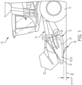
FIG. 1 is a side view of a front end of an agricultural combine harvester having a header (with a cutter bar) in a raised position above the ground, the header including a ground sensing apparatus and a forward-looking sensor. -
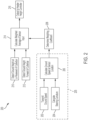
FIG. 2 is a simplified flow chart for header height control. -
FIG. 3 is a detailed view of the steps for calculating ground speed shown in the flow chart ofFIG. 2 . -
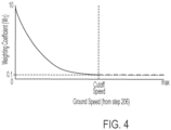
FIG. 4 is a graph showing the relationship between a weighting coefficient and ground speed. -
FIG. 5A is a simplified plan view of a combine and the location of forward looking sensors on the combine. -
FIG. 5B is another simplified plan view of the combine ofFIG. 5A shown in the course of moving or turning through a curve. - Corresponding reference characters indicate corresponding parts throughout the several views. The exemplification set out herein illustrates an embodiment of the invention, in one form, and such exemplification is not to be construed as limiting the scope of the invention in any manner.
- For convenience of reference and understanding in the following discussions, and with respect to the various drawings and their descriptions, the point of reference for the use of various terms that are hereafter employed, including "left", "right", "forward", "rearward", "front", "back", "top", and "bottom", should generally be considered to be taken from a point at the rear of the combine harvester machine facing in its normal direction of travel, unless it is clear from the discussion and context that a different point of reference is appropriate. Any use of such terms should therefore be considered exemplary and should not be construed as limiting or introducing limitations.
- Moreover, inasmuch as various components and features of harvesters and fan assemblies are of well-known design, construction, and operation to those skilled in the art, the details of such components and their operations will not generally be discussed in significant detail unless considered of pertinence to the present invention or desirable for purposes of better understanding.
- In the drawings, like numerals refer to like items, certain elements and features may be labeled or marked on a representative basis without each like element or feature necessarily being individually shown, labeled, or marked, and certain elements are labeled and marked in only some, but not all, of the drawing figures.
- Turning now to the drawings wherein a preferred embodiment of the invention is shown, in
FIG. 1 , a front end of anagricultural combine 10 is shown including aconventional header 12 supported on a feeder 14, for cutting or severing crops such as, but not limited to, legumes such as soybeans and small grains such as wheat, and inducting the severed crops into feeder 14 for conveyance into combine 10 for threshing and cleaning as thecombine 10 moves forwardly over a field.Header 12 includes a bottom orpan 16 which is supported in desired proximity to the ground surface of the field during the harvesting operation. An elongate, sidewardly extending cutter bar 18 supporting elongate, reciprocally movable sickle knives 20 (for example) is disposed along a forward edge ofpan 16. The cutter bar 18 severs the crop for induction into theheader 12. An elongate, sidewardly extendingreel 22 is disposed abovepan 16 and is rotatable in a direction for facilitating induction of the severed crops intoheader 12. An elongate,rotatable auger 24 extends in close proximity to a top surface ofpan 16 and has spiral flights therearound (not shown) which convey the severed crops to feeder 14 for induction intocombine 10. The front wheels 13 (or tracks) of thecombine 10 are shown inFIG. 1 . - Combine 10 includes a
ground speed sensor 17 for sensing the ground speed of thecombine 10 during operation. Theground speed sensor 17 may be a speedometer, GPS, or other speed sensing device of thecombine 10, as is known in the art. Theground speed sensor 17 may mounted or effectively mounted at the center axis G (FIG. 5A ) of thecombine 10 to determine the ground speed at the center axis G. -
Header 12 is shown including aground height sensor 26 constructed and operable according to teachings of the present invention, for sensing or contacting theground surface 28 of a field residing directly beneath theheader 12. Theground height sensor 26 is positioned either at or behind cutter bar 18. Theground height sensor 26 is configured to provide information relating to (i) the contour of theground 28 directly beneath the header, (ii) contact with the ground, and/or (iii) the height 'H' of the cutter bar 18 (or another point on the header 12) with respect to theground 28 at the current position ofheader 12, for example, to one or more controls ofcombine 10, such as an automatic header height control (not shown), a feeder height and/or angle control (also not shown), and/or a header tilt control (also not shown). The aforementioned controls may be managed by one or more controllers, such as thecontroller 50 that is described herein. Theground height sensor 26 does not necessarily have to contact the ground, and, may be a non-contact sensor that may utilize LIDAR, RADAR, or SONAR, and/orground sensor 26 may be ultrasonic sensor or camera. Further details of theground sensor 26 are provided in the `474 Patent. - A forwarding-looking sensor (FLS) 30 is mounted to
header 12 for sensing the contours (e.g., height) of theground 28 at a location forward ofheader 12. FLS 30 may utilize LIDAR, RADAR, or SONAR, and/or FLS 30 may be ultrasonic sensors or cameras. While FLS 30 may sense the elevation of ground contours that are forward ofheader 12, depending upon the type of FLS 30, FLS 30 does not necessarily detect the longitudinal distance to those contours. As noted above, when the combine is travelling at high ground speeds it would be advantageous to use sensing input from FLS 30 to provide advanced detection of ground contours. However, when the combine is travelling at low speed (e.g., 5 mph or less) while traversing aggressive ground contours, FLS 30 may detect contour changes too far in advance and causeheader 12 to prematurely move upward (or downward) or tilt about a center axis G of the combine 10 (FIG. 5A ), thereby resulting in sub-optimal harvesting. - FLS 30 and
ground sensor 26 represent a "sensor pair," and are positioned at the same lateral position along the length "L" (FIG. 5A ) of theheader 10. Theheader 12 includes at least onesensor pair 26/30. The example shown inFIG. 5A , for example, includes four sensor pairs A, B, C and D positioned along the length L of theheader 12. Each sensor pair A-D includes one FLS 30 and oneground sensor 26, for example. Theheader 12 may include any number of sensor pairs. - A
motor 29 raises and lowers the feeder 14 as well as theheader 12 that is connected thereto in a vertical direction, as is known in the art. Alternatively,motor 29 could raise or lower theheader 12 independently of the feeder 14. - Another motor or actuator 31 rotates (i.e., tilts) the
header 12 about the center axis G (FIG. 5A ), as is known in the art, to compensate for uneven ground conditions. Specifically, a series of actuators 31 may be spaced apart along the length L of theheader 12 for tilting theheader 12. - The
combine 10 further includes acontroller 50 that is configured to receive signals from thesensors 26 and 30, and actuate themotor 29 and actuators 31 to raise, lower and/or tilt theheader 12 based upon the signals from thesensors 26 and 30, as will be described in greater detail with reference toFIG. 2 . Thecontroller 50 incorporates automatic header height control, a feeder height and/or angle control, and/or a header tilt control. -
FIG. 2 is a simplified flow chart for header height control. The flowchart provides amethod 200 for controlling the height of theheader 12 relative to theground 28. It should be understood that themethod 200 described hereinafter is performed for asingle sensor pair 26/30 (i.e.,sensors 26 and 30 ofFIG. 1 ), and themethod 200 is repeated for everysensor pair 26/30 of thecombine 10. As noted above, the sensors of asensor pair 26/30 are positioned at the same lateral position along the length "L" (FIG. 5A ) of theheader 10. Also, it should be understood that the output of themethod 200 may also be used to control tilt of theheader 12. - According to the
method 200, atstep 202, theground speed sensor 17 transmits the ground speed of the machine (i.e., combine 10) or data corresponding thereto to thecontroller 50. Atstep 204, thecontroller 50 calculates the steering curvature of thecombine 10. Atstep 206, thecontroller 50 calculates the local ground speed at the location of thesensor pair 26/30 based upon the machine ground speed transmitted atstep 202 and the steering curvature transmitted atstep 204.Steps process 205 for calculating the local ground speed at the location of thesensor pair 26/30. Theprocess 205 is shown in simplified form inFIG. 2 , and in detailed form inFIG. 3 . Theprocess 205 will be described in greater detail with respect toFIG. 3 . - At
step 208, thecontroller 50 determines a weighting coefficient W1 based upon the local ground speed at thesensor pair 26/30 calculated atstep 206. The weighting coefficient W1 is determined using an equation or look-up table, for example. An exemplary graph of such an equation is shown inFIG. 4 . InFIG. 4 , the equation is a nonlinear, piecewise quadratic function, however, the equation could be linear (e.g., Y=X) without departing from the scope of the invention. Using any local ground speed (as determined at step 206), it is possible to calculate or identify a weighting coefficient W1 using the equation or look-up table. According to this example, the weighting coefficient W1 varies between 0.1 and 10, depending upon the local ground speed at thesensor pair 26/30, however, these values could vary. - The cutoff speed is identified on the graph in
FIG. 4 . The cutoff speed is the speed of the combine at which the function plotted on the graph transitions from a decaying value to a substantially constant value. The cutoff speed may be 5 miles per hour, for example. At the cutoff speed, the weighting coefficient W1 is 0.1. The purpose of the weighting coefficient W1 will be described in greater detail with reference to step 214. - At
step 210, the output of theground sensor 26 of thesensor pair 26/30 is transmitted to thecontroller 50. The output signal of theground sensor 26 corresponds to the detected vertical distance (i.e., height) from the ground to the cutter bar 18 (for example). As noted above,ground sensor 26 is positioned either at or rearward of the cutter bar 18 of thecombine 10. - At
step 212, the output of the FLS 30 of thesame sensor pair 26/30 is transmitted to thecontroller 50. As noted above, FLS 30 is positioned forward of the cutter bar 18 of thecombine 10. The output signal of the FLS 30 corresponds to the ground height at some location forward of the sensor 30 (e.g., depending upon the type, configuration and resolution of the FLS 30). The output signal of the FLS 30 may be output, for example, as (i) a vertical distance between the current ground position and the ground that is forward of the sensor 30, or (ii) a vertical distance between the cutter bar 18 and the location on the ground that is forward of the sensor 30. Thecontroller 50 is configured to manipulate the output signal, as required. - At
step 214, thecontroller 50 calculates the weighted header height output at the lateral location of onesensor pair 26/30 along the length L of theheader 12 using the function ofFIG. 4 in combination with the output data of the sensors of thatsensor pair 26/30. Specifically, thecontroller 50 calculates a weighted header height output for eachsensor pair 26/30 based upon the following formula:

- Input1 = header height value detected by
ground sensor 26 ofsensor pair 26/30 atstep 210; - Input2 = ground height value detected by FLS 30 of
sensor pair 26/30 atstep 212; - W1 = weighting coefficient calculated at
step 208; and - Output = weighted header height output at lateral location of
sensor pair 26/30. - The Output will vary depending upon the signals transmitted by the
sensors 26 and 30, the detected ground speed of thecombine 10 transmitted bysensor 17, as well as the detected steering curvature and the lateral location of thesensor pair 26/30 on the header 12 (as will be described with reference toFIG. 3 ). - In calculating the Output, for speeds above the cutoff speed shown in
FIG. 4 , no weight (or very little weight) is given to the output of theground sensor 26 of thesensor pair 26/30 whereas the output of the FLS 30 of thesame sensor pair 26/30 is heavily weighted. Conversely, for speeds below the cutoff speed, in calculating the Output, no weight (or very little weight) is given to the output of the FLS 30 of thesame sensor pair 26/30 whereas the output of theground sensor 26 of thesensor pair 26/30 is heavily weighted. Accordingly, when the combine is travelling at slow speeds (e.g., 5 mph or less) while traversing aggressive ground contours, contours detected by FLS 30 of thesensor pair 26/30 do not causeheader 12 to prematurely move upward (or downward) or tilt about axis G (FIG. 5A ), which would result in sub-optimal harvesting, because the output of FLS 30 is not weighted as heavily as the output of theground sensor 26 of thatsensor pair 26/30. The different weightings are made possible due to the weighting coefficient W1, which changes the Output depending upon the speed of thecombine 10. - At
step 216, the Output, i.e., the weighted header height at the lateral location ofsensor pair 26/30 is transmitted tocontroller 50. - As noted above,
method 200 is repeated for everysensor pair 26/30. Thus,controller 50 will receive an Output atstep 216 for everysensor pair 26/30, which may include, for example, four different sensor pairs A-D, as shown inFIG. 5A . Thecontroller 50 will then control themotor 29 and actuator 31 to raise, lower, and/or tilt theheader 12 depending upon the output calculated atstep 216 for everysensor pair 26/30 of theheader 12. -
FIG. 3 is a detailed view of the steps ofprocess 205 for calculating local ground speed at thesensor pair 26/30 while taking into consideration turning of thecombine 10. A turning operation executed by thecombine 10 is shown inFIG. 5B . As background, when the combine is driving in a straight line, all of the sensors of the sensor pairs 26/30 output the same ground speed, however, when thecombine 10 turns left or right, the sensor pairs 26/30 will output a different localized ground speed. As best shown inFIG. 5B , during operation, the sensor pair D will experience a lower local ground speed than the sensor pair A given their respective locations from the center of the turning radius. As will be described hereinafter, thecontroller 50 will take into account those different ground speeds upon calculating ground speed. It is noted that eachsensor 26 and 30 of aparticular sensor pair 26/30 will experience substantially the same ground speed during the turning operation of thecombine 10, however, the different sensor pairs 26/30 will experience different ground speeds during the turning operation, as detailed above. - At
step 302, thecontroller 50 detects the steering curvature of thecombine 10. The steering curvature of thecombine 10 may be detected using a steering sensor or a GPS of thecombine 10, or other means known to those skilled in the art for detecting turning of thecombine 10. - At
decision block 304, thecontroller 50 determines if the curvature of the combine is zero (0), and if the answer to that question is `YES', then the method proceeds to step 306. Atstep 306, thecontroller 50 sets the Gain to a numerical value of 1. The Gain is representative of the steering curvature, thus step 306 is representative ofstep 204 ofFIG. 2 . The method then proceeds to step 206, at which point thecontroller 50 calculates the ground speed for thesensor pair 26/30. The ground speed for thesensor pair 26/30, which compensates for the turning radius of thecombine 10, equals the product of the Gain and the machine ground speed that is calculated atstep 202. For acombine 10 having a steering curvature of zero, the Gain is set to one (as noted above), thus, the ground speed for thesensor pair 26/30 is equal to the machine ground speed that is calculated atstep 202. In other words, for acombine 10 having a steering curvature of zero, the ground speed for thesensor pair 26/30, which compensates for a non-existent turning radius, is simply equal to the machine ground speed that is calculated atstep 202. Theprocess 205 is then complete for thatsensor pair 26/30, and themethod 200 moves along to step 208 for thatsensor pair 26/30, as was described with reference toFIG. 2 . - Referring back to decision block 304, if the answer to the question at the
decision block 304 is 'NO,' indicating that thecombine 10 is executing a turning operation, then the method proceeds to step 308. Atstep 308, thecontroller 50 calculates the turning radius of thecombine 10. The value of the turning radius is 1/curvature. In differential geometry, the radius of curvature, R, (turning radius) is the reciprocal of the curvature. For a curve, the radius of curvature equals the radius of the circular arc which best approximates the curve at that point. Other ways of calculating the turning radius are known to those skilled in the art and may be used in performing themethod 200. Atstep 310, thecontroller 50 calculates the radiussensor , which is the turning radius of the combine at the lateral location of theparticular sensor pair 26/30. To calculate the radiussensor, thecontroller 50 subtracts (i) the distance of thesensor pair 26/30 from the center 'G' of the combine (as shown inFIG. 5A ), which may be either a positive or negative value, from (ii) the turning radius calculated atstep 308. Atstep 312, thecontroller 50 calculates a speed multiplier, which is the Gain, and which is equal to radiussensor divided by the turning radius calculated atstep 308. The Gain has a numerical value that is not equal to 1 (because thecombine 10 is executing a turn). The Gain is representative of the steering curvature, thus step 312 is representative ofstep 204 ofFIG. 2 . - The method then proceeds to step 206, at which point the
controller 50 calculates the local ground speed for thesensor pair 26/30. The local ground speed for thesensor pair 26/30, which compensates for the turning radius of thecombine 10, equals the product of the Gain that is calculated atstep 312 and the machine ground speed that is calculated atstep 202. Theprocess 205 is then complete for thatsensor pair 26/30, and the method moves along to step 208, as was described with reference toFIG. 2 . - As noted above,
process 205, along with the other steps ofmethod 200, are performed for eachsensor pair 26/30. - It is to be understood that the above-described operating steps are performed by the
controller 50 upon loading and executing software code or instructions which are tangibly stored on a tangible computer readable medium, such as on a magnetic medium, e.g., a computer hard drive, an optical medium, e.g., an optical disc, solid-state memory, e.g., flash memory, or other storage media known in the art. Thus, any of the functionality performed by thecontroller 50 described herein, such as the aforementioned method of operation, is implemented in software code or instructions which are tangibly stored on the tangible computer readable medium. Upon loading and executing such software code or instructions by the controller, the controller may perform any of the functionality of the controller described herein, including any steps of the aforementioned method described herein. - The term "software code" or "code" used herein refers to any instructions or set of instructions that influence the operation of a computer or controller. They may exist in a computer-executable form, such as machine code, which is the set of instructions and data directly executed by a computer's central processing unit or by a controller, a human-understandable form, such as source code, which may be compiled in order to be executed by a computer's central processing unit or by a controller, or an intermediate form, such as object code, which is produced by a compiler. As used herein, the term "software code" or "code" also includes any human-understandable computer instructions or set of instructions, e.g., a script, that may be executed on the fly with the aid of an interpreter executed by a computer's central processing unit or by a controller.
Claims (20)
- A combine harvester (10) comprising:a header (12) for harvesting crop material on the ground;a ground speed sensor (17) configured to detect a ground speed of the combine;a ground height sensor (26) configured to detect a contour of the ground located directly beneath the header (12);a forward looking sensor (FLS) (30) configured to detect a contour of the ground forward of the header (12); andwherein the combine harvester further comprises a controller (50) configured to receive signals from the ground speed sensor (17), the ground height sensor (26) and the forward looking sensor (30),characterized in that the controller is further configured to calculate a header height output as a function of (i) an output of the ground speed sensor (17), which represents a ground speed of the combine, (ii) an output of the ground height sensor (26), which represents the contour of the ground located directly beneath the header (12), and (iii) an output of the forward looking sensor (30), which represents the contour of the ground that is forward of the header (12),said controller (50) being further configured to weight the outputs of the ground speed sensor (17) and the forward looking sensor (30) as a function of the speed of the combine harvester in calculating the header height output.
- The combine harvester of claim 1, wherein the combine harvester further comprises a motor (29) or actuator for either raising or lowering the header (12), wherein said controller (50) is configured to operate the motor (29) to either raise or lower the header (12) based upon the header height output.
- The combine harvester of any one of the foregoing claims, wherein said header (12) including a cutter bar (18), the ground height sensor (26) being configured to detect the contour of the ground located directly beneath the cutter bar (18), and the forward looking sensor (30) being configured to detect the contour of the ground that is forward of the header (12).
- The combine harvester of any one of the foregoing claims, wherein at a first ground speed of the combine, the controller (50) is configured to weight the output of the forward looking sensor (30) higher than the output of the ground height sensor (26) in calculating the header height output, and at a second ground speed of the combine that is lower than the first ground speed, the controller (50) is configured to weight the output of the ground height sensor (26) higher than the output of the forward looking sensor (30) in calculating the header height output.
- The combine harvester of any one of the foregoing claims, wherein the FLS (30) and the ground height sensor (26) form a sensor pair (26/30), and the sensor pair (26/30) is positioned at a same lateral location on the header (12).
- The combine harvester of claim 5, wherein the combine harvester further comprises a plurality of sensor pairs (26/30), wherein the sensor pairs (26/30) are spaced apart along a lateral length of the header (12).
- The combine harvester of claim 6, wherein the controller (50) is further configured to calculate a header height output for each sensor pair (26/30).
- The combine harvester of claim 7, wherein the combine harvester further comprises an actuator (31) for tilting the header (12), and wherein the controller (50) is further to control the actuator based upon the header height output for each sensor pair (26/30).
- The combine harvester of claim 7, characterized in that , for each sensor pair (26/30), the controller (50) is configured to modify the output of the ground speed sensor (17) as a function of (i) a turning radius of the combine (10), and (ii) a lateral location of the sensor pair (26/30) along a length of the header (12).
- The combine harvester of any one of the foregoing claims, characterized in that , in weighting of the outputs of the ground height sensor (26) and the forward looking sensor (30), the controller (50) is configured to utilize either a function or a look-up table that provides different weighting coefficients for various ground speeds of the combine.
- The combine harvester of any one of the foregoing claims, wherein the controller (50) is configured to calculate the header height output based upon the formula:
 Input1 is the output of the ground height sensor (26);Input2 is the output of the forward looking sensor (30);W1 is a weighting coefficient that is a function of the ground speed; andOutput is the header height output.
 - The combine harvester of any one of the foregoing claims, wherein the ground height sensor (26) is configured to directly contact the ground and the forward looking sensor (30) is not configured to contact the ground.
- A method for controlling a height of a header (12) of a combine, the combine comprising a ground speed sensor (17) configured to detect a ground speed of the combine, a ground height sensor (26) configured to detect a contour of the ground located directly beneath the header (12), and a forward looking sensor (FLS) (30) configured to detect a contour of the ground forward of the header (12), wherein the method comprises:
receiving signals at a controller (50) of the header (12) or the combine from the ground speed sensor (17), the ground height sensor (26) and the forward looking sensor (30), characterized in that the method further comprises:calculating a header height output, using the controller (50), as a function of (i) an output of the ground speed sensor (17), which represents a ground speed of the combine, (ii) an output of the ground height sensor (26), which represents the contour of the ground located directly beneath the header (12), and (iii) an output of the forward looking sensor (30), which represents the contour of the ground that is forward of the header (12), andweighting, by the controller (50), of the outputs of the ground height sensor (26) and the forward looking sensor (30) as a function of the speed of the combine harvester in calculating the header height output. - The method of claim 13, wherein the method comprises calculating the header height output based upon the formula:
 Input1 is the output of the ground height sensor (26);Input2 is the output of the forward looking sensor (30);W1 is a weighting coefficient that is a function of the ground speed; andOutput is the header height output.
 - The method of either claim 13 or 14, wherein the combine further includes a motor (29) or actuator for either raising or lowering the header (12), and the method further comprises operating the motor (29) to either raise of lower the header (12) based upon the header height output.
- The method of any one of claims 13-15, wherein at a first ground speed of the combine, the method comprises weighting the output of the forward looking sensor (30) higher than the output of the ground height sensor (26) in calculating the header height output, and at a second ground speed of the combine that is lower than the first ground speed, the method comprises weighting the output of the ground height sensor (26) higher than the output of the forward looking sensor (30) in calculating the header height output.
- The method of any one of claims 13-16, wherein the forward looking sensor (30) and the ground height sensor (26) form a sensor pair (26/30), and the sensor pair (26/30) is positioned at a same lateral location along a length of the header (12).
- The method of claim 17, wherein the combine harvester further comprises a plurality of sensor pairs (26/30), wherein the sensor pairs (26/30) are spaced apart along a lateral length of the header (12).
- The method of claim 18, wherein the method comprises calculating a header height output for each sensor pair (26/30).
- The method of claim 18, wherein for each sensor pair (26/30), the method further comprises modifying the output of the ground speed sensor (17) as a function of (i) a turning radius of the combine, and (ii) a lateral location of the sensor pair (26/30) along a length of the header (12).
Applications Claiming Priority (2)
| Application Number | Priority Date | Filing Date | Title |
|---|---|---|---|
| US202063031934P | 2020-05-29 | 2020-05-29 | |
| PCT/US2021/034268 WO2021242867A1 (en) | 2020-05-29 | 2021-05-26 | Header height control for combine harvester |
Publications (2)
| Publication Number | Publication Date |
|---|---|
| EP4156895A1 EP4156895A1 (en) | 2023-04-05 |
| EP4156895B1 true EP4156895B1 (en) | 2024-07-10 |
Family
ID=76744917
Family Applications (1)
| Application Number | Title | Priority Date | Filing Date |
|---|---|---|---|
| EP21737234.1A Active EP4156895B1 (en) | 2020-05-29 | 2021-05-26 | Header height control for combine harvester |
Country Status (5)
| Country | Link |
|---|---|
| US (1) | US11812695B2 (en) |
| EP (1) | EP4156895B1 (en) |
| AU (1) | AU2021281222A1 (en) |
| BR (1) | BR112022023976A2 (en) |
| WO (1) | WO2021242867A1 (en) |
Families Citing this family (8)
| Publication number | Priority date | Publication date | Assignee | Title |
|---|---|---|---|---|
| EP4231821B1 (en) * | 2020-10-26 | 2026-04-08 | Precision Planting LLC | Vision system |
| US12364181B2 (en) | 2020-11-02 | 2025-07-22 | Deere & Company | Agricultural characteristic confidence and control |
| US12022772B2 (en) | 2021-01-22 | 2024-07-02 | Deere & Company | Agricultural header control |
| US12550821B2 (en) | 2022-03-15 | 2026-02-17 | Deere & Company | Systems and methods for predictive reel control |
| US12302788B2 (en) | 2022-04-08 | 2025-05-20 | Deere &Company | Residue characteristic confidence and control |
| AU2023307061A1 (en) * | 2022-07-14 | 2025-02-06 | Cnh Industrial America Llc | Systems and methods for header height control |
| US12593741B2 (en) | 2022-09-21 | 2026-04-07 | Cnh Industrial America Llc | Agricultural system and method for monitoring field characteristics of a field |
| US12507628B2 (en) | 2022-10-13 | 2025-12-30 | Deere & Company | Agricultural system with deck plate positioning control |
Citations (3)
| Publication number | Priority date | Publication date | Assignee | Title |
|---|---|---|---|---|
| US20020069628A1 (en) * | 2000-12-06 | 2002-06-13 | Metzger Leo A. | Sensor arm for combine header |
| EP1269823A1 (en) * | 2001-06-28 | 2003-01-02 | Deere & Company | System for adjusting the header of a harvesting machine |
| EP1716738A1 (en) * | 2005-04-29 | 2006-11-02 | CNH Belgium N.V. | Ground sensing apparatus for a header of an agricultural harvesting machine |
Family Cites Families (22)
| Publication number | Priority date | Publication date | Assignee | Title |
|---|---|---|---|---|
| US5359836A (en) * | 1993-02-01 | 1994-11-01 | Control Concepts, Inc. | Agricultural harvester with closed loop header control |
| DE4406892A1 (en) * | 1994-03-03 | 1995-09-07 | Bosch Gmbh Robert | Device for controlling the ground clearance of a processing unit of an agricultural machine |
| US5577373A (en) * | 1994-06-24 | 1996-11-26 | Case Corporation | Agricultural vehicle including a system for automatically moving an implement and improved ground height sensing to a predetermined operating position |
| DE10011499A1 (en) * | 2000-03-09 | 2001-09-20 | Case Harvesting Sys Gmbh | Device for following contour of soil with cutter mounted on crop feeder of harvesting machine comprises divider carrying ground sensor which controls hydraulic cylinder for raising and lowering crop feeder |
| US6591591B2 (en) * | 2001-07-30 | 2003-07-15 | Deere & Company | Harvester speed control with header position input |
| DE10227484A1 (en) * | 2002-06-19 | 2004-02-26 | Claas Selbstfahrende Erntemaschinen Gmbh | Device and method for controlling the position of a harvesting device of agricultural harvesting machines |
| US8333057B2 (en) * | 2011-01-06 | 2012-12-18 | Cnh America Llc | Automatic header lateral tilt to ground speed response |
| DE102012012907A1 (en) * | 2012-06-28 | 2014-04-17 | Claas Selbstfahrende Erntemaschinen Gmbh | Self-propelled harvester with height-controlled cutting unit |
| WO2014127043A1 (en) * | 2013-02-12 | 2014-08-21 | Headsight, Inc. | Automatic calibration system for header height controller with operator feedback |
| US9668412B2 (en) * | 2015-05-01 | 2017-06-06 | Deere & Company | Harvesting head height control circuit |
| US9769982B2 (en) * | 2015-09-09 | 2017-09-26 | Cnh Industrial America Llc | Method and apparatus for automatically controlling a cut height of an agricultural harvester |
| US9980431B2 (en) * | 2016-09-12 | 2018-05-29 | Cnh Industrial America Llc | Header height control system with multiple height sensors |
| US10182525B2 (en) * | 2017-05-17 | 2019-01-22 | Cnh Industrial America Llc | Feeder and header positioning method |
| US10455765B2 (en) * | 2017-08-31 | 2019-10-29 | Cnh Industrial America Llc | Method and system for controlling the height of agricultural implement relative to the ground |
| EP3720265B1 (en) * | 2017-12-08 | 2021-12-15 | AGCO Corporation | Flexible header with sectional height adjustment |
| US10687466B2 (en) * | 2018-01-29 | 2020-06-23 | Cnh Industrial America Llc | Predictive header height control system |
| DE102018107804A1 (en) * | 2018-04-03 | 2019-10-10 | Claas Selbstfahrende Erntemaschinen Gmbh | Height control system for a header |
| DE102018206507A1 (en) * | 2018-04-26 | 2019-10-31 | Deere & Company | Cutting unit with automatic adjustment of the hook tine orientation |
| US20190335661A1 (en) | 2018-05-07 | 2019-11-07 | CNH Industrial America, LLC | Method and system for controlling the height of an agricultural implement relative to the ground |
| CN109548472A (en) | 2019-01-07 | 2019-04-02 | 中国农业大学 | CAN bus based harvest corn harvesting damage control system and control method |
| US11382267B2 (en) * | 2020-01-15 | 2022-07-12 | Cnh Industrial America Llc | Harvesting header height control |
| US11737390B2 (en) * | 2021-02-23 | 2023-08-29 | Cnh Industrial America Llc | Harvesting header multi-sensor height control |
-
2021
- 2021-05-26 US US17/926,509 patent/US11812695B2/en active Active
- 2021-05-26 AU AU2021281222A patent/AU2021281222A1/en active Pending
- 2021-05-26 EP EP21737234.1A patent/EP4156895B1/en active Active
- 2021-05-26 WO PCT/US2021/034268 patent/WO2021242867A1/en not_active Ceased
- 2021-05-26 BR BR112022023976A patent/BR112022023976A2/en unknown
Patent Citations (3)
| Publication number | Priority date | Publication date | Assignee | Title |
|---|---|---|---|---|
| US20020069628A1 (en) * | 2000-12-06 | 2002-06-13 | Metzger Leo A. | Sensor arm for combine header |
| EP1269823A1 (en) * | 2001-06-28 | 2003-01-02 | Deere & Company | System for adjusting the header of a harvesting machine |
| EP1716738A1 (en) * | 2005-04-29 | 2006-11-02 | CNH Belgium N.V. | Ground sensing apparatus for a header of an agricultural harvesting machine |
Also Published As
| Publication number | Publication date |
|---|---|
| WO2021242867A1 (en) | 2021-12-02 |
| US11812695B2 (en) | 2023-11-14 |
| US20230134768A1 (en) | 2023-05-04 |
| EP4156895A1 (en) | 2023-04-05 |
| AU2021281222A1 (en) | 2022-12-15 |
| BR112022023976A2 (en) | 2022-12-20 |
Similar Documents
| Publication | Publication Date | Title |
|---|---|---|
| US11812695B2 (en) | Header height control for combine harvester | |
| EP4039078B1 (en) | Header fore/aft tilt control for combine harvester | |
| EP3516942B1 (en) | Predictive header height control system | |
| US10806078B2 (en) | Control system for adjusting conditioning rollers of work vehicle | |
| US10813287B2 (en) | Control system for adjusting swath flap of windrowing work vehicle | |
| US10912255B2 (en) | Control system for adjusting forming shield of windrowing work vehicle | |
| EP3400780B1 (en) | System for automatically controlling conditioning and windrowing arrangements of a work vehicle | |
| EP3509412B1 (en) | Header height control system with multiple height sensors | |
| US11737390B2 (en) | Harvesting header multi-sensor height control | |
| US12245550B2 (en) | Calibration system for an agricultural header | |
| EP3011824A1 (en) | Sensor equipped agricultural harvester | |
| EP1269823B1 (en) | System for adjusting the header of a harvesting machine | |
| US20220338416A1 (en) | Harvesting headers having leading sensors, agricultural machines carrying such headers, and related methods | |
| US11793111B2 (en) | Harvesting head reel-mounted laser measurement | |
| JP2020135793A (en) | Automatic travel system | |
| JP2023144102A (en) | work vehicle | |
| US20260107879A1 (en) | Radar support structure for sugarcane harvester | |
| US20250176464A1 (en) | Proactive variable control of harvester header positioning |
Legal Events
| Date | Code | Title | Description |
|---|---|---|---|
| STAA | Information on the status of an ep patent application or granted ep patent |
Free format text: STATUS: UNKNOWN |
|
| STAA | Information on the status of an ep patent application or granted ep patent |
Free format text: STATUS: THE INTERNATIONAL PUBLICATION HAS BEEN MADE |
|
| PUAI | Public reference made under article 153(3) epc to a published international application that has entered the european phase |
Free format text: ORIGINAL CODE: 0009012 |
|
| STAA | Information on the status of an ep patent application or granted ep patent |
Free format text: STATUS: REQUEST FOR EXAMINATION WAS MADE |
|
| 17P | Request for examination filed |
Effective date: 20230102 |
|
| AK | Designated contracting states |
Kind code of ref document: A1 Designated state(s): AL AT BE BG CH CY CZ DE DK EE ES FI FR GB GR HR HU IE IS IT LI LT LU LV MC MK MT NL NO PL PT RO RS SE SI SK SM TR |
|
| DAV | Request for validation of the european patent (deleted) | ||
| DAX | Request for extension of the european patent (deleted) | ||
| GRAP | Despatch of communication of intention to grant a patent |
Free format text: ORIGINAL CODE: EPIDOSNIGR1 |
|
| STAA | Information on the status of an ep patent application or granted ep patent |
Free format text: STATUS: GRANT OF PATENT IS INTENDED |
|
| INTG | Intention to grant announced |
Effective date: 20231222 |
|
| GRAS | Grant fee paid |
Free format text: ORIGINAL CODE: EPIDOSNIGR3 |
|
| GRAA | (expected) grant |
Free format text: ORIGINAL CODE: 0009210 |
|
| STAA | Information on the status of an ep patent application or granted ep patent |
Free format text: STATUS: THE PATENT HAS BEEN GRANTED |
|
| AK | Designated contracting states |
Kind code of ref document: B1 Designated state(s): AL AT BE BG CH CY CZ DE DK EE ES FI FR GB GR HR HU IE IS IT LI LT LU LV MC MK MT NL NO PL PT RO RS SE SI SK SM TR |
|
| REG | Reference to a national code |
Ref country code: CH Ref legal event code: EP |
|
| REG | Reference to a national code |
Ref country code: DE Ref legal event code: R096 Ref document number: 602021015534 Country of ref document: DE |
|
| REG | Reference to a national code |
Ref country code: LT Ref legal event code: MG9D |
|
| REG | Reference to a national code |
Ref country code: NL Ref legal event code: MP Effective date: 20240710 |
|
| PG25 | Lapsed in a contracting state [announced via postgrant information from national office to epo] |
Ref country code: PT Free format text: LAPSE BECAUSE OF FAILURE TO SUBMIT A TRANSLATION OF THE DESCRIPTION OR TO PAY THE FEE WITHIN THE PRESCRIBED TIME-LIMIT Effective date: 20241111 |
|
| REG | Reference to a national code |
Ref country code: AT Ref legal event code: MK05 Ref document number: 1701159 Country of ref document: AT Kind code of ref document: T Effective date: 20240710 |
|
| PG25 | Lapsed in a contracting state [announced via postgrant information from national office to epo] |
Ref country code: NL Free format text: LAPSE BECAUSE OF FAILURE TO SUBMIT A TRANSLATION OF THE DESCRIPTION OR TO PAY THE FEE WITHIN THE PRESCRIBED TIME-LIMIT Effective date: 20240710 |
|
| PG25 | Lapsed in a contracting state [announced via postgrant information from national office to epo] |
Ref country code: PT Free format text: LAPSE BECAUSE OF FAILURE TO SUBMIT A TRANSLATION OF THE DESCRIPTION OR TO PAY THE FEE WITHIN THE PRESCRIBED TIME-LIMIT Effective date: 20241111 Ref country code: NL Free format text: LAPSE BECAUSE OF FAILURE TO SUBMIT A TRANSLATION OF THE DESCRIPTION OR TO PAY THE FEE WITHIN THE PRESCRIBED TIME-LIMIT Effective date: 20240710 |
|
| PG25 | Lapsed in a contracting state [announced via postgrant information from national office to epo] |
Ref country code: NO Free format text: LAPSE BECAUSE OF FAILURE TO SUBMIT A TRANSLATION OF THE DESCRIPTION OR TO PAY THE FEE WITHIN THE PRESCRIBED TIME-LIMIT Effective date: 20241010 |
|
| PG25 | Lapsed in a contracting state [announced via postgrant information from national office to epo] |
Ref country code: FI Free format text: LAPSE BECAUSE OF FAILURE TO SUBMIT A TRANSLATION OF THE DESCRIPTION OR TO PAY THE FEE WITHIN THE PRESCRIBED TIME-LIMIT Effective date: 20240710 Ref country code: GR Free format text: LAPSE BECAUSE OF FAILURE TO SUBMIT A TRANSLATION OF THE DESCRIPTION OR TO PAY THE FEE WITHIN THE PRESCRIBED TIME-LIMIT Effective date: 20241011 Ref country code: PL Free format text: LAPSE BECAUSE OF FAILURE TO SUBMIT A TRANSLATION OF THE DESCRIPTION OR TO PAY THE FEE WITHIN THE PRESCRIBED TIME-LIMIT Effective date: 20240710 |
|
| PG25 | Lapsed in a contracting state [announced via postgrant information from national office to epo] |
Ref country code: BG Free format text: LAPSE BECAUSE OF FAILURE TO SUBMIT A TRANSLATION OF THE DESCRIPTION OR TO PAY THE FEE WITHIN THE PRESCRIBED TIME-LIMIT Effective date: 20240710 |
|
| PG25 | Lapsed in a contracting state [announced via postgrant information from national office to epo] |
Ref country code: LV Free format text: LAPSE BECAUSE OF FAILURE TO SUBMIT A TRANSLATION OF THE DESCRIPTION OR TO PAY THE FEE WITHIN THE PRESCRIBED TIME-LIMIT Effective date: 20240710 |
|
| PG25 | Lapsed in a contracting state [announced via postgrant information from national office to epo] |
Ref country code: AT Free format text: LAPSE BECAUSE OF FAILURE TO SUBMIT A TRANSLATION OF THE DESCRIPTION OR TO PAY THE FEE WITHIN THE PRESCRIBED TIME-LIMIT Effective date: 20240710 Ref country code: IS Free format text: LAPSE BECAUSE OF FAILURE TO SUBMIT A TRANSLATION OF THE DESCRIPTION OR TO PAY THE FEE WITHIN THE PRESCRIBED TIME-LIMIT Effective date: 20241110 |
|
| PG25 | Lapsed in a contracting state [announced via postgrant information from national office to epo] |
Ref country code: HR Free format text: LAPSE BECAUSE OF FAILURE TO SUBMIT A TRANSLATION OF THE DESCRIPTION OR TO PAY THE FEE WITHIN THE PRESCRIBED TIME-LIMIT Effective date: 20240710 |
|
| PG25 | Lapsed in a contracting state [announced via postgrant information from national office to epo] |
Ref country code: RS Free format text: LAPSE BECAUSE OF FAILURE TO SUBMIT A TRANSLATION OF THE DESCRIPTION OR TO PAY THE FEE WITHIN THE PRESCRIBED TIME-LIMIT Effective date: 20241010 Ref country code: ES Free format text: LAPSE BECAUSE OF FAILURE TO SUBMIT A TRANSLATION OF THE DESCRIPTION OR TO PAY THE FEE WITHIN THE PRESCRIBED TIME-LIMIT Effective date: 20240710 |
|
| PG25 | Lapsed in a contracting state [announced via postgrant information from national office to epo] |
Ref country code: RS Free format text: LAPSE BECAUSE OF FAILURE TO SUBMIT A TRANSLATION OF THE DESCRIPTION OR TO PAY THE FEE WITHIN THE PRESCRIBED TIME-LIMIT Effective date: 20241010 Ref country code: PL Free format text: LAPSE BECAUSE OF FAILURE TO SUBMIT A TRANSLATION OF THE DESCRIPTION OR TO PAY THE FEE WITHIN THE PRESCRIBED TIME-LIMIT Effective date: 20240710 Ref country code: NO Free format text: LAPSE BECAUSE OF FAILURE TO SUBMIT A TRANSLATION OF THE DESCRIPTION OR TO PAY THE FEE WITHIN THE PRESCRIBED TIME-LIMIT Effective date: 20241010 Ref country code: LV Free format text: LAPSE BECAUSE OF FAILURE TO SUBMIT A TRANSLATION OF THE DESCRIPTION OR TO PAY THE FEE WITHIN THE PRESCRIBED TIME-LIMIT Effective date: 20240710 Ref country code: IS Free format text: LAPSE BECAUSE OF FAILURE TO SUBMIT A TRANSLATION OF THE DESCRIPTION OR TO PAY THE FEE WITHIN THE PRESCRIBED TIME-LIMIT Effective date: 20241110 Ref country code: HR Free format text: LAPSE BECAUSE OF FAILURE TO SUBMIT A TRANSLATION OF THE DESCRIPTION OR TO PAY THE FEE WITHIN THE PRESCRIBED TIME-LIMIT Effective date: 20240710 Ref country code: GR Free format text: LAPSE BECAUSE OF FAILURE TO SUBMIT A TRANSLATION OF THE DESCRIPTION OR TO PAY THE FEE WITHIN THE PRESCRIBED TIME-LIMIT Effective date: 20241011 Ref country code: FI Free format text: LAPSE BECAUSE OF FAILURE TO SUBMIT A TRANSLATION OF THE DESCRIPTION OR TO PAY THE FEE WITHIN THE PRESCRIBED TIME-LIMIT Effective date: 20240710 Ref country code: ES Free format text: LAPSE BECAUSE OF FAILURE TO SUBMIT A TRANSLATION OF THE DESCRIPTION OR TO PAY THE FEE WITHIN THE PRESCRIBED TIME-LIMIT Effective date: 20240710 Ref country code: BG Free format text: LAPSE BECAUSE OF FAILURE TO SUBMIT A TRANSLATION OF THE DESCRIPTION OR TO PAY THE FEE WITHIN THE PRESCRIBED TIME-LIMIT Effective date: 20240710 Ref country code: AT Free format text: LAPSE BECAUSE OF FAILURE TO SUBMIT A TRANSLATION OF THE DESCRIPTION OR TO PAY THE FEE WITHIN THE PRESCRIBED TIME-LIMIT Effective date: 20240710 |
|
| REG | Reference to a national code |
Ref country code: DE Ref legal event code: R097 Ref document number: 602021015534 Country of ref document: DE |
|
| PG25 | Lapsed in a contracting state [announced via postgrant information from national office to epo] |
Ref country code: DK Free format text: LAPSE BECAUSE OF FAILURE TO SUBMIT A TRANSLATION OF THE DESCRIPTION OR TO PAY THE FEE WITHIN THE PRESCRIBED TIME-LIMIT Effective date: 20240710 Ref country code: SM Free format text: LAPSE BECAUSE OF FAILURE TO SUBMIT A TRANSLATION OF THE DESCRIPTION OR TO PAY THE FEE WITHIN THE PRESCRIBED TIME-LIMIT Effective date: 20240710 Ref country code: RO Free format text: LAPSE BECAUSE OF FAILURE TO SUBMIT A TRANSLATION OF THE DESCRIPTION OR TO PAY THE FEE WITHIN THE PRESCRIBED TIME-LIMIT Effective date: 20240710 |
|
| PG25 | Lapsed in a contracting state [announced via postgrant information from national office to epo] |
Ref country code: EE Free format text: LAPSE BECAUSE OF FAILURE TO SUBMIT A TRANSLATION OF THE DESCRIPTION OR TO PAY THE FEE WITHIN THE PRESCRIBED TIME-LIMIT Effective date: 20240710 |
|
| PG25 | Lapsed in a contracting state [announced via postgrant information from national office to epo] |
Ref country code: CZ Free format text: LAPSE BECAUSE OF FAILURE TO SUBMIT A TRANSLATION OF THE DESCRIPTION OR TO PAY THE FEE WITHIN THE PRESCRIBED TIME-LIMIT Effective date: 20240710 |
|
| PG25 | Lapsed in a contracting state [announced via postgrant information from national office to epo] |
Ref country code: SK Free format text: LAPSE BECAUSE OF FAILURE TO SUBMIT A TRANSLATION OF THE DESCRIPTION OR TO PAY THE FEE WITHIN THE PRESCRIBED TIME-LIMIT Effective date: 20240710 |
|
| PLBE | No opposition filed within time limit |
Free format text: ORIGINAL CODE: 0009261 |
|
| STAA | Information on the status of an ep patent application or granted ep patent |
Free format text: STATUS: NO OPPOSITION FILED WITHIN TIME LIMIT |
|
| 26N | No opposition filed |
Effective date: 20250411 |
|
| PGFP | Annual fee paid to national office [announced via postgrant information from national office to epo] |
Ref country code: DE Payment date: 20250528 Year of fee payment: 5 |
|
| PGFP | Annual fee paid to national office [announced via postgrant information from national office to epo] |
Ref country code: GB Payment date: 20250520 Year of fee payment: 5 |
|
| PGFP | Annual fee paid to national office [announced via postgrant information from national office to epo] |
Ref country code: IT Payment date: 20250522 Year of fee payment: 5 |
|
| PGFP | Annual fee paid to national office [announced via postgrant information from national office to epo] |
Ref country code: FR Payment date: 20250526 Year of fee payment: 5 |
|
| PG25 | Lapsed in a contracting state [announced via postgrant information from national office to epo] |
Ref country code: SE Free format text: LAPSE BECAUSE OF FAILURE TO SUBMIT A TRANSLATION OF THE DESCRIPTION OR TO PAY THE FEE WITHIN THE PRESCRIBED TIME-LIMIT Effective date: 20240710 |
|
| REG | Reference to a national code |
Ref country code: CH Ref legal event code: H13 Free format text: ST27 STATUS EVENT CODE: U-0-0-H10-H13 (AS PROVIDED BY THE NATIONAL OFFICE) Effective date: 20251223 |
|
| PG25 | Lapsed in a contracting state [announced via postgrant information from national office to epo] |
Ref country code: LU Free format text: LAPSE BECAUSE OF NON-PAYMENT OF DUE FEES Effective date: 20250526 |
|
| PG25 | Lapsed in a contracting state [announced via postgrant information from national office to epo] |
Ref country code: CH Free format text: LAPSE BECAUSE OF NON-PAYMENT OF DUE FEES Effective date: 20250531 |
|
| REG | Reference to a national code |
Ref country code: BE Ref legal event code: MM Effective date: 20250531 |
|
| PG25 | Lapsed in a contracting state [announced via postgrant information from national office to epo] |
Ref country code: MC Free format text: LAPSE BECAUSE OF FAILURE TO SUBMIT A TRANSLATION OF THE DESCRIPTION OR TO PAY THE FEE WITHIN THE PRESCRIBED TIME-LIMIT Effective date: 20240710 |
|
| PG25 | Lapsed in a contracting state [announced via postgrant information from national office to epo] |
Ref country code: IE Free format text: LAPSE BECAUSE OF NON-PAYMENT OF DUE FEES Effective date: 20250526 |
|
| PG25 | Lapsed in a contracting state [announced via postgrant information from national office to epo] |
Ref country code: BE Free format text: LAPSE BECAUSE OF NON-PAYMENT OF DUE FEES Effective date: 20250531 |