EP4156590B1 - Gemeinsame bandbreitenteilumschaltung für eine gruppe von benutzergeräten - Google Patents
Gemeinsame bandbreitenteilumschaltung für eine gruppe von benutzergeräten Download PDFInfo
- Publication number
- EP4156590B1 EP4156590B1 EP22197245.8A EP22197245A EP4156590B1 EP 4156590 B1 EP4156590 B1 EP 4156590B1 EP 22197245 A EP22197245 A EP 22197245A EP 4156590 B1 EP4156590 B1 EP 4156590B1
- Authority
- EP
- European Patent Office
- Prior art keywords
- base station
- downlink
- bwp
- communications
- guard band
- Prior art date
- Legal status (The legal status is an assumption and is not a legal conclusion. Google has not performed a legal analysis and makes no representation as to the accuracy of the status listed.)
- Active
Links
Images



Classifications
-
- H—ELECTRICITY
- H04—ELECTRIC COMMUNICATION TECHNIQUE
- H04W—WIRELESS COMMUNICATION NETWORKS
- H04W72/00—Local resource management
- H04W72/04—Wireless resource allocation
- H04W72/044—Wireless resource allocation based on the type of the allocated resource
- H04W72/0453—Resources in frequency domain, e.g. a carrier in FDMA
-
- H—ELECTRICITY
- H04—ELECTRIC COMMUNICATION TECHNIQUE
- H04J—MULTIPLEX COMMUNICATION
- H04J11/00—Orthogonal multiplex systems, e.g. using WALSH codes
- H04J11/0023—Interference mitigation or co-ordination
- H04J11/0026—Interference mitigation or co-ordination of multi-user interference
-
- H—ELECTRICITY
- H04—ELECTRIC COMMUNICATION TECHNIQUE
- H04L—TRANSMISSION OF DIGITAL INFORMATION, e.g. TELEGRAPHIC COMMUNICATION
- H04L27/00—Modulated-carrier systems
- H04L27/26—Systems using multi-frequency codes
- H04L27/2601—Multicarrier modulation systems
- H04L27/2602—Signal structure
-
- H—ELECTRICITY
- H04—ELECTRIC COMMUNICATION TECHNIQUE
- H04L—TRANSMISSION OF DIGITAL INFORMATION, e.g. TELEGRAPHIC COMMUNICATION
- H04L27/00—Modulated-carrier systems
- H04L27/26—Systems using multi-frequency codes
- H04L27/2601—Multicarrier modulation systems
- H04L27/2602—Signal structure
- H04L27/26025—Numerology, i.e. varying one or more of symbol duration, subcarrier spacing, Fourier transform size, sampling rate or down-clocking
-
- H—ELECTRICITY
- H04—ELECTRIC COMMUNICATION TECHNIQUE
- H04L—TRANSMISSION OF DIGITAL INFORMATION, e.g. TELEGRAPHIC COMMUNICATION
- H04L27/00—Modulated-carrier systems
- H04L27/26—Systems using multi-frequency codes
- H04L27/2601—Multicarrier modulation systems
- H04L27/2602—Signal structure
- H04L27/2605—Symbol extensions, e.g. Zero Tail, Unique Word [UW]
- H04L27/2607—Cyclic extensions
-
- H—ELECTRICITY
- H04—ELECTRIC COMMUNICATION TECHNIQUE
- H04L—TRANSMISSION OF DIGITAL INFORMATION, e.g. TELEGRAPHIC COMMUNICATION
- H04L5/00—Arrangements affording multiple use of the transmission path
- H04L5/003—Arrangements for allocating sub-channels of the transmission path
- H04L5/0037—Inter-user or inter-terminal allocation
- H04L5/0041—Frequency-non-contiguous
-
- H—ELECTRICITY
- H04—ELECTRIC COMMUNICATION TECHNIQUE
- H04L—TRANSMISSION OF DIGITAL INFORMATION, e.g. TELEGRAPHIC COMMUNICATION
- H04L5/00—Arrangements affording multiple use of the transmission path
- H04L5/003—Arrangements for allocating sub-channels of the transmission path
- H04L5/0058—Allocation criteria
- H04L5/0073—Allocation arrangements that take into account other cell interferences
-
- H—ELECTRICITY
- H04—ELECTRIC COMMUNICATION TECHNIQUE
- H04L—TRANSMISSION OF DIGITAL INFORMATION, e.g. TELEGRAPHIC COMMUNICATION
- H04L5/00—Arrangements affording multiple use of the transmission path
- H04L5/0091—Signalling for the administration of the divided path, e.g. signalling of configuration information
- H04L5/0092—Indication of how the channel is divided
-
- H—ELECTRICITY
- H04—ELECTRIC COMMUNICATION TECHNIQUE
- H04L—TRANSMISSION OF DIGITAL INFORMATION, e.g. TELEGRAPHIC COMMUNICATION
- H04L5/00—Arrangements affording multiple use of the transmission path
- H04L5/0091—Signalling for the administration of the divided path, e.g. signalling of configuration information
- H04L5/0096—Indication of changes in allocation
-
- H—ELECTRICITY
- H04—ELECTRIC COMMUNICATION TECHNIQUE
- H04L—TRANSMISSION OF DIGITAL INFORMATION, e.g. TELEGRAPHIC COMMUNICATION
- H04L5/00—Arrangements affording multiple use of the transmission path
- H04L5/14—Two-way operation using the same type of signal, i.e. duplex
-
- H—ELECTRICITY
- H04—ELECTRIC COMMUNICATION TECHNIQUE
- H04L—TRANSMISSION OF DIGITAL INFORMATION, e.g. TELEGRAPHIC COMMUNICATION
- H04L5/00—Arrangements affording multiple use of the transmission path
- H04L5/14—Two-way operation using the same type of signal, i.e. duplex
- H04L5/1469—Two-way operation using the same type of signal, i.e. duplex using time-sharing
-
- H—ELECTRICITY
- H04—ELECTRIC COMMUNICATION TECHNIQUE
- H04W—WIRELESS COMMUNICATION NETWORKS
- H04W72/00—Local resource management
- H04W72/04—Wireless resource allocation
- H04W72/044—Wireless resource allocation based on the type of the allocated resource
- H04W72/0457—Variable allocation of band or rate
-
- H—ELECTRICITY
- H04—ELECTRIC COMMUNICATION TECHNIQUE
- H04W—WIRELESS COMMUNICATION NETWORKS
- H04W72/00—Local resource management
- H04W72/20—Control channels or signalling for resource management
- H04W72/23—Control channels or signalling for resource management in the downlink direction of a wireless link, i.e. towards a terminal
-
- H—ELECTRICITY
- H04—ELECTRIC COMMUNICATION TECHNIQUE
- H04W—WIRELESS COMMUNICATION NETWORKS
- H04W72/00—Local resource management
- H04W72/20—Control channels or signalling for resource management
- H04W72/23—Control channels or signalling for resource management in the downlink direction of a wireless link, i.e. towards a terminal
- H04W72/232—Control channels or signalling for resource management in the downlink direction of a wireless link, i.e. towards a terminal the control data signalling from the physical layer, e.g. DCI signalling
-
- H—ELECTRICITY
- H04—ELECTRIC COMMUNICATION TECHNIQUE
- H04W—WIRELESS COMMUNICATION NETWORKS
- H04W72/00—Local resource management
- H04W72/50—Allocation or scheduling criteria for wireless resources
- H04W72/56—Allocation or scheduling criteria for wireless resources based on priority criteria
-
- H—ELECTRICITY
- H04—ELECTRIC COMMUNICATION TECHNIQUE
- H04L—TRANSMISSION OF DIGITAL INFORMATION, e.g. TELEGRAPHIC COMMUNICATION
- H04L5/00—Arrangements affording multiple use of the transmission path
- H04L5/003—Arrangements for allocating sub-channels of the transmission path
- H04L5/0058—Allocation criteria
- H04L5/0064—Rate requirement of the data, e.g. scalable bandwidth, data priority
Definitions
- the present disclosure relates to the field of wireless communication, and more particularly, to mechanisms for managing cross-link interference (CLI) by causing a group of user equipments (UEs) to switch their respective bandwidth parts.
- CLI cross-link interference
- Cross-link interference may occur when a first UE (referred to as an aggressor UE) transmits to a base station while a second UE (referred to as a victim UE) is receiving from the base station, especially if the transmit frequency of the first UE is too close to the reception frequency of the second UE.
- a first UE referred to as an aggressor UE
- a second UE referred to as a victim UE
- US2021/0194663 discloses systems for interference measurement and reporting for UEs, which measurements may be used to determine guard bands between UL and DL signals.
- US2021/0152418 discloses a system in which UEs can identify frequency bands for full-duplex communications and can signal their capability to support such communication to a base station.
- WO2021/158480 discloses a system in which UEs receive configurations for full-duplex communications from a base station.
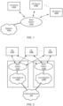
- Figures 1 and 2 illustrate exemplary (and simplified) wireless communication systems. It is noted that the systems of Figures 1 and 2 are merely examples of certain possible systems, and various embodiments may be implemented in any of various ways, as desired.
- the wireless communication system of Figure 1 includes a base station 102A which communicates over a transmission medium with one or more user equipment (UE) devices 106A, 106B, etc., through 106N.
- UE user equipment
- Each of the user equipment devices may be referred to herein as "user equipment” (UE).
- base station 102B in addition to the base station 102A, base station 102B also communicates (e.g., simultaneously or concurrently) over a transmission medium with the UE devices 106A, 106B, etc., through 106N.
- the base stations 102A and 102B may be base transceiver stations (BTSs) or cell sites, and may include hardware that enables wireless communication with the user devices 106A through 106N.
- Each base station 102 may also be equipped to communicate with a core network 100 (e.g., base station 102A may be coupled to core network 100A, while base station 102B may be coupled to core network 100B), which may be a core network of a cellular service provider.
- Each core network 100 may be coupled to one or more external networks (such as external network 108), which may include the Internet, a Public Switched Telephone Network (PSTN), or any other network.
- PSTN Public Switched Telephone Network
- the base station 102A may facilitate communication between the user devices and/or between the user devices and the network 100A; in the system of Figure 2 , the base station 102B may facilitate communication between the user devices and/or between the user devices and the network 100B.
- the base stations 102A and 102B and the user devices may be configured to communicate over the transmission medium using any of various radio access technologies (RATs), also referred to as wireless communication technologies, or telecommunication standards, such as GSM, UMTS (WCDMA), LTE, LTE-Advanced (LTE-A), 5G New Radio (NR), 3GPP2 CDMA2000 (e.g., 1xRTT, 1xEV-DO, HRPD, eHRPD), Wi-Fi, WiMAX etc.
- RATs radio access technologies
- WCDMA UMTS
- LTE Long Term Evolution
- LTE-A LTE-Advanced
- NR 5G New Radio
- 3GPP2 CDMA2000 e.g., 1xRTT, 1xEV-DO, HRPD, eHRPD
- Wi-Fi WiMAX etc.
- base station 102A and core network 100A may operate according to a first cellular communication standard (e.g., 5G NR) while base station 102B and core network 100B operate according to a second cellular communication standard.
- the second cellular communication standard e.g., LTE, GSM, UMTS, and/or one or more CDMA2000 cellular communication standards
- the two networks may be controlled by the same network operator (e.g., cellular service provider or "carrier"), or by different network operators.
- the two networks may be operated independently of one another (e.g., if they operate according to different cellular communication standards), or may be operated in a somewhat coupled or tightly coupled manner.
- base stations 102A and 102B might operate according to different cellular communication standards but couple to the same core network.
- multi-mode base stations capable of simultaneously supporting different cellular communication technologies (e.g., 5G NR and LTE, LTE and CDMA 1xRTT, GSM and UMTS, or any other combination of cellular communication technologies) might be coupled to a core network that also supports the different cellular communication technologies. Any of various other network deployment scenarios are also possible.
- base station 102A and base station 102B may operate according to the same wireless communication technology (or an overlapping set of wireless communication technologies).
- base station 102A and core network 100A may be operated by one cellular service provider independently of base station 102B and core network 100B, which may be operated by a different (e.g., competing) cellular service provider.
- the UE devices 106A-106N might communicate with the base stations 102A-102B independently, possibly by utilizing separate subscriber identities to communicate with different carriers' networks.
- a UE 106 may be capable of communicating using multiple wireless communication standards.
- a UE 106 might be configured to communicate using either or both of a 3GPP cellular communication standard (such as LTE) or a 3GPP2 cellular communication standard (such as a cellular communication standard in the CDMA2000 family of cellular communication standards).
- a UE 106 might be configured to communicate using different 3GPP cellular communication standards (such as two or more of GSM, UMTS, LTE, LTE-A, or 5G NR).
- a UE 106 might be configured to communicate with base station 102A (and/or other base stations) according to a first cellular communication standard (e.g., 5G NR) and might also be configured to communicate with base station 102B (and/or other base stations) according to a second cellular communication standard (e.g., LTE).
- a first cellular communication standard e.g., 5G NR
- a second cellular communication standard e.g., LTE
- Base stations 102A and 102B and other base stations operating according to the same or different cellular communication standards may support one or more networks of cells, which may provide continuous or nearly continuous overlapping service to UEs 106A-106N and similar devices over a wide geographic area via one or more cellular communication standards.
- a UE 106 might also or alternatively be configured to communicate using WLAN, Bluetooth, one or more global navigational satellite systems (GNSS, e.g., GPS or GLONASS), one and/or more mobile television broadcasting standards (e.g., ATSC-M/H or DVB-H), etc.
- GNSS global navigational satellite systems
- GLONASS global navigational satellite systems
- ATSC-M/H ATSC-M/H or DVB-H
- Other combinations of wireless communication standards are also possible.
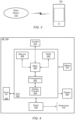
- Figure 3 illustrates user equipment 106 (e.g., one of the devices 106A through 106N) in communication with a base station 102 (e.g., one of the base stations 102A or 102B).
- the UE 106 may be a device with wireless network connectivity such as a mobile phone, a hand-held device, a satellite phone, a computer or a tablet, a wearable device or virtually any type of wireless device.
- the UE may include a processor that is configured to execute program instructions stored in memory.
- the UE may perform any of the method embodiments described herein by executing such stored instructions.
- the UE may include a programmable hardware element such as an FPGA (field-programmable gate array) that is configured to perform any of the method embodiments described herein, or any portion of any of the method embodiments described herein.
- FPGA field-programmable gate array
- the UE 106 may be configured to communicate using any of multiple wireless communication protocols.
- the UE 106 may be configured to communicate using two or more of GSM, UMTS (W-CDMA, TD-SCDMA, etc.), CDMA2000 (1xRTT, 1xEV-DO, HRPD, eHRPD, etc.), LTE, LTE-A, 5G New Radio (NR), WLAN, or GNSS.
- GSM Global System for Mobile communications
- the UE 106 may include one or more antennas (or, one or more antenna arrays) for communicating using one or more wireless communication protocols.
- one or more parts of a receive and/or transmit chain may be shared between multiple wireless communication standards; for example, the UE 106 might be configured to communicate using either (or both) of LTE or 5G NR using a single shared radio.
- the shared radio may include a single antenna, or may include a plurality of antennas (e.g., for MIMO and/or beamforming) for performing wireless communications. (MIMO is an acronym for Multi-Input Multiple-Output.)
- the antennas may be organized in one or more arrays.
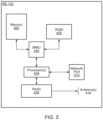
- FIG. 4 illustrates an example of a block diagram of a UE 106.
- the UE 106 may include a system on chip (SOC) 300, which may include portions for various purposes.
- the SOC 300 may include processor(s) 302 which may execute program instructions for the UE 106 and display circuitry 304 which may perform graphics processing and provide display signals to the display 345.
- the processor(s) 302 may also be coupled to memory management unit (MMU) 340, which may be configured to receive addresses from the processor(s) 302 and translate those addresses to locations in memory (e.g., memory 306, read only memory (ROM) 350, NAND flash memory 310) and/or to other circuits or devices, such as the display circuitry 304, radio 330, connector I/F 320, and/or display 345.
- MMU memory management unit
- the MMU 340 may be configured to perform memory protection and page table translation or set up. In some embodiments, the MMU 340 may be included as a portion of the processor(s) 302.
- the SOC 300 may be coupled to various other circuits of the UE 106.
- the UE 106 may include various types of memory (e.g., including Flash memory 310), a connector interface 320 (e.g., for coupling to a computer system, dock, charging station, etc.), the display 345, and radio 330.
- the radio 330 may include one or more RF chains. Each RF chain may include a transmit chain, a receive chain, or both. For example, radio 330 may include two RF chains to support dual connectivity with two base stations (or two cells).
- the radio may be configured to support wireless communication according to one or more wireless communication standards, e.g., one or more of GSM, UMTS, LTE, LTE-A, 5G NR, WCDMA, CDMA2000, Bluetooth, Wi-Fi, GPS, etc.
- the radio 330 couples to antenna subsystem 335, which includes one or more antennas.
- the antenna subsystem 335 may include a plurality of antennas (e.g., organized in one or more arrays) to support applications such as dual connectivity or MIMO and/or beamforming.
- the antenna subsystem 335 transmits and receives radio signals to/from one or more base stations or devices through the radio propagation medium.
- the processor(s) 302 may include a baseband processor to generate uplink baseband signals and/or to process downlink baseband signals.
- the processor(s) 302 may be configured to perform data processing according to one or more wireless telecommunication standards, e.g., one or more of GSM, UMTS, LTE, LTE-A, 5G NR, WCDMA, CDMA2000, Bluetooth, Wi-Fi, GPS, etc.
- the UE 106 may also include one or more user interface elements.
- the user interface elements may include any of various elements, such as display 345 (which may be a touchscreen display), a keyboard (which may be a discrete keyboard or may be implemented as part of a touchscreen display), a mouse, a microphone and/or speakers, one or more cameras, one or more sensors, one or more buttons, sliders, and/or dials, and/or any of various other elements capable of providing information to a user and/or receiving /interpreting user input.
- the UE 106 may also include one or more subscriber identity modules (SIMs) 360.
- SIMs subscriber identity modules
- Each of the one or more SIMs may be implemented as an embedded SIM (eSIM), in which case the SIM may be implemented in device hardware and/or software.
- the UE 106 may include an embedded UICC (eUICC), e.g., a device which is built into the UE 106 and is not removable.
- eUICC embedded UICC
- the eUICC may be programmable, such that one or more eSIMs may be implemented on the eUICC.
- the eSIM may be installed in UE 106 software, e.g., as program instructions stored on a memory medium (such as memory 306 or Flash 310) executing on a processor (such as processor 302) in the UE 106.
- a SIM 360 may be an application which executes on a Universal Integrated Circuit Card (UICC).
- UICC Universal Integrated Circuit Card
- one or more of the SIMs 360 may be implemented as removable SIM cards.
- the processor 302 of the UE device 106 may be configured to implement part or all of the methods described herein, e.g., by executing program instructions stored on a memory medium (e.g., a non-transitory computer-readable memory medium).
- processor 302 may be configured as or include: a programmable hardware element, such as an FPGA (Field Programmable Gate Array); or an ASIC (Application Specific Integrated Circuit); or a combination thereof.
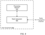
- FIG. 5 illustrates a block diagram of a base station 102. It is noted that the base station of Figure 5 is merely one example of a possible base station. As shown, the base station 102 may include processor(s) 404 which may execute program instructions for the base station 102. The processor(s) 404 may also be coupled to memory management unit (MMU) 440, which may be configured to receive addresses from the processor(s) 404 and translate those addresses to locations in memory (e.g., memory 460 and read only memory ROM 450) or to other circuits or devices.
- MMU memory management unit
- the base station 102 may include at least one network port 470.
- the network port 470 may be configured to couple to a telephone network and provide access (for a plurality of devices, such as UE devices 106) to the telephone network, as described above in Figures 1 and 2 .
- the network port 470 may also or alternatively be configured to couple to a cellular network, e.g., a core network of a cellular service provider.
- the core network may provide mobility related services and/or other services to a plurality of devices, such as UE devices 106.
- the network port 470 may couple to a telephone network via the core network, and/or the core network may provide the telephone services (e.g., among UE devices served by the network provider).
- the base station 102 may include a radio 430 having one or more RF chains. Each RF chain may include a transmit chain, a receive chain, or both. (For example, the base station 102 may include at least one RF chain per sector or cell.)
- the radio 430 couples to antenna subsystem 434, which includes one or more antennas, or one or more arrays of antennas. A plurality of antennas would be needed, e.g., to support applications such as MIMO and/or beamforming.
- the antenna subsystem 434 transmits and receives radio signals to/from UEs through the radio propagation medium.
- the processor(s) 404 may include a baseband processor to generate downlink baseband signals and/or to process uplink baseband signals.
- the baseband processor may be configured to operate according to one or more wireless telecommunication standards, including, but not limited to, GSM, LTE, 5G New Radio, WCDMA, CDMA2000, etc.
- the processor(s) 404 of the base station 102 may be configured to implement any of the methods described herein, e.g., by executing program instructions stored on a memory medium (e.g., a non-transitory computer-readable memory medium).
- the processor(s) 404 may include: a programmable hardware element, such as an FPGA (Field Programmable Gate Array); or an ASIC (Application Specific Integrated Circuit); or a combination thereof.
- a wireless user equipment (UE) device 600 may be configured as shown in Figure 6 .
- UE device 600 may include: a radio subsystem 605 for performing wireless communication; and a processing element 610 operatively coupled to the radio subsystem.
- UE device 600 may also include any subset of the UE features described above, e.g., in connection with Figures 1-4 .
- the radio subsystem 605 may include one or more RF chains, e.g., as variously described above. Each RF chain may be configured to receive signals from the radio propagation channel and/or transmit signals onto the radio propagation channel. Thus, each RF chain may include a transmit chain and/or a receive chain.
- the radio subsystem 605 may be coupled to one or more antennas (or one or more arrays of antennas) to facilitate signal transmission and reception. Each transmit chain (or some of the transmit chains) may be tunable to a desired frequency, thus allowing the transmit chain to transmit at different frequencies at different times. Similarly, each receive chain (or some of the receive chains) may be tunable to a desired frequency, thus allowing the receive chain to receive at different frequencies at different times.
- the processing element 610 may be coupled to the radio subsystem, and may be configured as variously described above. (For example, processing element may be realized by processor(s) 302.) The processing element may be configured to control the state of each RF chain in the radio subsystem. The processing element may be configured to perform any of the UE-based method embodiments described herein.
- the processing element may include one or more baseband processors to (a) generate baseband signals to be transmitted by the radio subsystem and/or (b) process baseband signals provided by the radio subsystem.
- the processing element may direct a first RF chain to communicate with a first base station using a first radio access technology and direct a second RF chain to communicate with a second base station using a second radio access technology.
- the first RF chain may communicate with an LTE eNB
- the second RF chain may communicate with a gNB of 5G New Radio (NR).
- the link with the LTE eNB may be referred to as the LTE branch.
- the link with the gNB may be referred to as the NR branch.
- the processing element may include a first subcircuit for baseband processing with respect to the LTE branch and a second subcircuit for baseband processing with respect to the NR branch.
- the processing element 610 may be further configured as variously described in the sections below.
- the UE device 600 may include memory (e.g., any of the memories described above in connection with user equipment 106 of Figure 6 , or any combination of those memories) that stores program instructions to implement any of the UE method embodiments described herein, e.g., program instructions to be executed by the processing element 610.
- memory e.g., any of the memories described above in connection with user equipment 106 of Figure 6 , or any combination of those memories
- a wireless base station 700 of a wireless network may be configured as shown in Figure 7 .
- the wireless base station may include: a radio subsystem 705 for performing wireless communication over a radio propagation channel; and a processing element 710 operatively coupled to the radio subsystem.
- the wireless base station may also include any subset of the base station features described above, e.g., the features described above in connection with Figure 5 .
- the wireless base station may host one or more cells.
- the radio subsystem 705 may include one or more RF chains. Each transmit/receive chain may be tunable to a desired frequency, thus allowing the transmit/receive chain to transmit/receive at different frequencies at different times.
- the radio subsystem 705 may be coupled to an antenna subsystem, including one or more antennas, e.g., an array of antennas, or a plurality of antenna arrays.
- the radio subsystem may employ the antenna subsystem to transmit and receive radio signals to/from the radio wave propagation medium.
- processing element 710 may be realized as variously described above.
- processing element 710 may be realized by processor(s) 404.
- the processing element may include one or more baseband processors to: (a) generate baseband signals to be transmitted by the radio subsystem, and/or, (b) process baseband signals provided by the radio subsystem.
- the processing element 710 may be configured to perform any of the base station method embodiments described herein.
- the base station 700 may include memory (e.g., memory 460 of base station 102 of Figure 5 , or some other memory) that stores program instructions to implement any of the base station method embodiments described herein, e.g., program instructions to be executed by the processing element 710.
- memory e.g., memory 460 of base station 102 of Figure 5 , or some other memory
- program instructions to implement any of the base station method embodiments described herein, e.g., program instructions to be executed by the processing element 710.
- SB-FD Sub-band Full Duplex
- FD Full-duplex
- Figure 8 illustrates an example of the contrast between a Frequency Domain Duplex (FDD) slot and a Time Domain Duplex (TDD) slot, according to traditional distinctions.
- Sub-band full-duplex (SB-FD) within a TDD band may aim to mimic FDD for which uplink (UL) latency is reduced, by allowing a first UE to transmit to the base station within a first frequency sub-band and a second UE to receive from the base station within a second frequency sub-band.
- UL uplink
- Both the first and second frequency sub-bands may be within a frequency band reserved (e.g., allocated, defined by applicable standards, etc.) for TDD communications, such as FR2, as defined by 3GPP.
- FD we may refer to the case where (at least) the base station (e.g., gNB) is operating in full-duplex, i.e., simultaneously transmitting and receiving.
- each UE may continue to implement TDD communications within one or more sub-bands of the TDD frequency band.
- uplink (UL) transmissions from a first UE may overlap in time with downlink (DL) reception by a second UE.
- FIG. 9 illustrates an example of UE-to-UE CLI, where an aggressor UE (UE A ) is transmitting to the base station, while a victim UE (UE V ) is receiving from the base station, according to some embodiments.
- CLI may include out-of-band noise, harmonics, or any other energy transmitted by UE A at frequencies within the frequency range at which the UE V is receiving.
- a full-duplex base station (e.g., gNB) should be able to manage this CLI, at least for intra-cell UE-to-UE interference.
- UE-to-UE CLI may be managed using scheduler-based techniques.
- Scheduler-based techniques for CLI management may include techniques based on spatial separation and/or techniques based on separation in frequency.
- the aggressor UE and victim UEs are spatially separated.
- the scheduler may require a pair of UEs that offer the potential of CLI to be sufficiently separated in distance.
- a guard band may be placed between the transmission allocation for aggressor UE and the reception allocation for the victim UE, e.g., as illustrated in Figure 10 .
- Some signaling between UEs and/or between the UE(s) and the serving base station may be utilized to better achieve this purpose.
- At least one of the victim UE or the aggressor UE may determine a minimum required (or requested) guard band between the DL resources of the victim UE and the UL resources associated with an aggressor UE, e.g., as shown in Figure 10 .
- a guard band can be in units of frequency, number of physical resource blocks (PRBs) for each tone spacing, etc.
- PRBs physical resource blocks
- such a GB can be defined between an edge tone of the aggressor UE's UL bandwidth part (BWP) and an edge tone of the victim UE's DL BWP.
- such a GB can instead be defined between an edge tone of the resource allocation for UE A and an edge tone of the resource allocation for UE V .
- a determined GB that is defined between an edge tone of the resource allocation for UE A and an edge tone of the resource allocation for UE V may be greater than the frequency range between the edge tone of the aggressor UL BWP and the edge tone of the victim DL BWP, e.g., if the resource allocation for one or both of the UEs avoids resources near the edge of the respective BWP.
- a combination of the two approaches may be used.
- a UE may determine multiple minimum GB values, e.g., depending on various criteria. For example, the UE may determine multiple minimum GB values based on possible priority values of the downlink channel. E.g., the UE may determine a first minimum GB value for ultra-reliable low latency communications (URLLC) communications and a second (e.g., smaller) minimum GB value for enhanced mobile broadband (eMBB) communications, because URLLC communications may be more susceptible to disruption by CLI. As another example, the UE may determine multiple minimum GB values based on types of downlink signal/channel that is being (or may be) received.
- URLLC ultra-reliable low latency communications
- eMBB enhanced mobile broadband
- the UE may determine a first minimum GB value for use when receiving dynamic physical downlink shared channel (PDSCH) communications and a second GB value for use when receiving semi-persistent scheduling (SPS) communications. Or the UE may determine a first GB value for use when receiving data and a second GB value for use when receiving channel state information reference signal (CSI-RS) communications.
- PDSCH dynamic physical downlink shared channel
- SPS semi-persistent scheduling
- CSI-RS channel state information reference signal
- the one or more minimum GB values may therefore be determined based on any of a number of factors relevant to managing CLI.
- a GB value may be determined based at least in part on expected levels of out-of-band noise, expected harmonic values, susceptibility of expected DL signals to CLI, priority levels of expected DL signals, signal type and/or channel of expected DL signals, etc.
- a UE may estimate a minimum GB value that will prevent out-of-band noise within the DL BWP beyond some threshold level.
- the threshold level may be adjusted based on priority levels of expected DL signals, signal type and/or channel of expected DL signals, etc.
- At least one of the victim UE or the aggressor UE may indicate the determined minimum required GB(s) to the base station.
- the UE may indicate the minimum required guard band(s) as part of the UE capability signaling.
- at least one of the UEs may indicate the determined minimum required GB(s) at other times, e.g., dynamically, based on which of multiple determined minimum GBs is currently applicable.
- the base station may receive the indication of the determined guard band and may ensure the guard band requirement is satisfied, to prevent interference leakage from UE A to UE V .
- the base station may ensure that the BWPs and/or the allocated resources are separated by at least the indicated minimum guard band.
- a BWP assigned to a UE may be changed, e.g., in response to changing resource needs or requests of the UE.
- the base station may indicate a new BWP assignment to a UE.
- UEs may be individually indicated to switch BWP. For example, in paired spectrum, an active UL BWP of a UE and an active DL BWP of the UE can switch independently, per UE. In unpaired spectrum, the active UL BWP of the UE and the active DL BWP of the UE may switch together, per UE.
- a single message such as a group common downlink control information (GC-DCI) message may be defined (or used) to indicate UEs that may switch active BWPs together (i.e., jointly). This indication may enable better management of UE-to-UE CLI.
- GC-DCI group common downlink control information
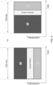
- the base station may allocate to an aggressor UE (UE A ) a first UL BWP 1102 in time for UE A to transmit within the first UL BWP 1102 at a first time (T 0 ).
- the base station may allocate to a victim UE (UE V ) a first DL BWP 1106 in time for UE V to receive within the first DL BWP 1106 at T 0 .
- the base station may allocate a first guard band 1104 between the first UL BWP 1102 and the first DL BWP 1106, to prevent (or reduce) CLI between the two UEs.
- the first guard band 1104 may be allocated with a frequency width of at least a minimum guard band previously indicated by one or more of the UEs, e.g., as outlined above.
- the base station may subsequently allocate to UE A a larger, second UL BWP 1112 to UE A .
- the base station may allocate a second guard band 1114 with a frequency width of at least the minimum guard band previously indicated by one or more of the UEs, e.g., as outlined above. To maintain this minimum guard band, the base station may allocate a correspondingly smaller second DL BWP 1116 to UE V .
- the total frequency band used by the second UL BWP 1112, the second guard band 1114, and the second DL BWP 1116 may be the same (or substantially the same) as the total frequency band used by the first UL BWP 1102, the first guard band 1104, and the first DL BWP 1106.
- the DL BWP may be decreased by approximately the same amount by which the UL BWP was increased.
- the base station may signal the change in UL BWP allocated to UE A and the change in DL BWP allocated to UE V within a single message, such as a single GC-DCI, transmitted to both UE A and UE V .
- a single message such as a single GC-DCI
- each of UE A and UE V may utilize the respective newly allocated BWP to transmit or receive at a second time (T 1 ).
- the first DL BWP 1106 and the second DL BWP 1116 may be usable by a plurality of victim UEs.
- the base station may signal the change in UL BWP and the change in DL BWP within a single message transmitted to both UE A and each UE of the plurality of victim UEs.
- the base station may transmit a single message, such as a GC-DCI, to UE A and UE V (and to other victim UEs, as appliable), similarly indicating an increase in a DL BWP and a corresponding decrease in an UL BWP, while maintaining a previously indicated minimum guard band between them.
- a single message such as a GC-DCI
- the base station may transmit a single message to at least UE A and UE V , indicating a change in allocation of at least one of the DL BWP and/or the UL BWP, wherein the change in allocation reflects a change in the size of the guard band.
- the base station may determine that a different minimum guard band is appropriate, e.g., based on a plurality of minimum guard bands previously provided by a UE, as discussed above. The base station may therefore change the allocation of at least one of the DL BWP and/or the UL BWP to accommodate the change in size of the guard band.
- a single reference may be employed for all UEs affected by the single BWP switching message (UEs for which a new BWP is allocated), such that all the affected UEs will know how to follow the timeline.
- a reference SCS is supported. The minimum switching delay may be defined based on the reference SCS for all affected UEs. Because the affected UEs may not all have the same SCS, the reference SCS may be different from the SCS of one or more of the affected UEs.
- the reference SCS may be transmitted to the UEs by higher layer signaling. Alternatively, the reference SCS can be indicated as part of group common downlink control information (GC-DCI), e.g., the GC-DCI used to communicate the changes in BWPs, or another GC-DCI.
- GC-DCI group common downlink control information
- a BWP switch delay is defined from the beginning of DL slot in which the affected UEs are expected to receive GC-DCI indicating joint BWP switch.
- one or more of the affected UEs may acknowledge the joint BWP switch indication.
- both the victim and the aggressor UEs may acknowledge the joint BWP switch indication, e.g., by transmitting to the base station a message including an acknowledgment.
- the aggressor UE may be required to acknowledge the joint BWP switch indication.
- victim UEs may forgo providing any acknowledgement to the base station.
- the base station may be able to operate without such an explicit acknowledgement, at least in some scenarios. For example, if the joint BWP switch message indicates that the DL BWP has been reduced, then the base station may avoid scheduling any DL resources within the region that is no longer included in the updated DL BWP.
- a UE having a BWP that was reduced in size by the joint BWP switch indication may continue to operate effectively (if less efficiently), even if the joint BWP switch indication is not received thereby, because the base station will not schedule transmission or reception for that UE within the region removed from the BWP applicable to that UE.
- the acknowledgement may be sent on a medium access control (MAC) control element (MAC-CE), e.g., on the new BWP or current BWP, or it can be sent on a physical uplink control channel (PUCCH).
- MAC-CE medium access control control element
- PUCCH physical uplink control channel
- the resource for the PUCCH transmission can be indicated to the UE as part of GC-DCI, e.g., the GC-DCI used to communicate the changes in BWPs, or another GC-DCI.
- an acknowledge message may be sent by a UE to the base station in response to completion of the switch to the new bandwidth part.
- transmission or reception of one of the UEs may lie within the BWP switch delay.
- one or more repetition occasions may fall within the BWP switch delay.
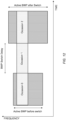
- Figure 12 illustrates an example of such a situation, in which a first repetition occasion (Occasion 0) occurs prior to BWP switching, a second repetition occasion (Occasion 1) occurs within the BWP switch delay period, and a third repetition occasion (Occasion 2) occurs after BWP switching.
- any repetition occasion scheduled to occur within the BWP switch delay may be dropped (e.g., the UE may forgo transmitting or receiving the repetition). If any repetition occasions are scheduled to occur after the BWP switch delay, such occasions may be used within the new active BWP. For example, within the context illustrated in Figure 12 , a first repetition may be transmitted within Occasion 0, according to the original BWP allocation, but Occasion 1 may be dropped. At Occasion 2, another repetition may be transmitted, according to the new BWP allocation.
- behavior may be the same as in the first embodiment, except that the number of repetitions may be extended in the new active BWP, e.g., to compensate for the dropped repetitions during the BWP switch delay.
- the total number of available repetitions may be the same as (or similar to) the number of repetitions that would have occurred if there was no switch.
- the total number of available repetitions may be the same as (or similar to) the number of repetitions configured by a network or specified by a wireless communication standard.
- a first repetition may be transmitted within Occasion 0, according to the original BWP allocation, but no transmission may occur within the BWP switch delay period in which Occasion 1 was originally scheduled.
- Occasion 1 and Occasion 2 may both occur following the BWP switch delay, according to the new BWP allocation.
- the rest of the occasions are used if the Frequency Domain Resource Allocation (FDRA) matches in the new active BWP.
- FDRA Frequency Domain Resource Allocation
- a first repetition may be transmitted within Occasion 0, according to the original BWP allocation, but all subsequent occasions may be dropped.
- the UE does not expect such a BWP switch indication.
- the base station may be constrained to delay any BWP switch (or any joint BWP switch) until all scheduled repetition occasions have occurred.
- any BWP switch or any joint BWP switch
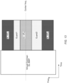
- a virtual common DL BWP may be defined which overlaps with the actual DL BWPs and UL BWPs of victim UEs and aggressor UEs, respectively.
- This large virtual DL-BWP may have the same center frequency as the UL BWP.
- the UL BWP(s) of one or more aggressor UEs may be grouped in around the center of the virtual common DL BWP, and the DL BWPs of the victim UEs may be placed at the ends of the virtual common DL-BWP, e.g., as shown in Figure 13 , according to some embodiments.
- a first guard band may be placed between the UL BWP(s) and the DL BWP(s) at the upper end, and a second guard band may be placed between the UL BWP(s) and the DL BWP(s) at the lower end.
- the guard bands may be of sufficient size to allow an increase in size of the UL BWP(s) without necessitating a decrease in the size of the DL BWPs.
- the UE(s) in DL do not necessarily need to switch to smaller actual DL BWP(s), e.g., even when the UL BWP of an aggressor UE is increased to a larger size. It is sufficient for a UE to know what is the actual DL-BWP (or actual DL-BWP size) for the UE, and how Frequency-Domain Resource Allocation (FDRA) for the UE is derived.
- the smaller size of the actual DL-BWPs can save DCI bit size for FDRA indication in DL grants.
- a virtual common DL BWP may be defined which overlaps with the actual DL BWPs of victim UE(s) and the UL BWPs of aggressor UE(s).
- a non-transitory memory medium may store program instructions.
- the program instructions when executed by processing circuitry, may cause the processing circuitry to perform any of the method embodiments described above, and any combination of those embodiments.
- the memory medium may be incorporated as part of a base station.
- Embodiments of the present disclosure may be realized in any of various forms. For example, some embodiments may be realized as a computer-implemented method, a computer-readable memory medium, or a computer system. Other embodiments may be realized using one or more custom-designed hardware devices such as ASICs. Still other embodiments may be realized using one or more programmable hardware elements such as FPGAs.
- a non-transitory computer-readable memory medium may be configured so that it stores program instructions and/or data, where the program instructions, if executed by a computer system, cause the computer system to perform a method, e.g., any of the method embodiments described herein, or, any combination of the method embodiments described herein, or, any subset of any of the method embodiments described herein, or, any combination of such subsets.
- a computer system may be configured to include a processor (or a set of processors) and a memory medium, where the memory medium stores program instructions, where the processor is configured to read and execute the program instructions from the memory medium, where the program instructions are executable to implement any of the various method embodiments described herein (or, any combination of the method embodiments described herein, or, any subset of any of the method embodiments described herein, or, any combination of such subsets).
- the computer system may be realized in any of various forms.
- the computer system may be a personal computer (in any of its various realizations), a workstation, a computer on a card, an application-specific computer in a box, a server computer, a client computer, a hand-held device, a user equipment (UE) device, a tablet computer, a wearable computer, etc.
- a personal computer in any of its various realizations
- a workstation in any of its various realizations
- a computer on a card an application-specific computer in a box
- a server computer a client computer
- a hand-held device a user equipment (UE) device
- UE user equipment
- Any of the methods described herein for operating a user equipment (UE) in communication with a base station (or transmission-reception point) may be the basis of a corresponding method for operating a base station (or transmission-reception point), by interpreting each message/signal X received by the UE in the downlink as a message/signal X transmitted by the base station (or transmission-reception point), and each message/signal Y transmitted in the uplink by the UE as a message/signal Y received by the base station (or transmission-reception point).
- personally identifiable information should follow privacy policies and practices that are generally recognized as meeting or exceeding industry or governmental requirements for maintaining the privacy of users.
- personally identifiable information data should be managed and handled so as to minimize risks of unintentional or unauthorized access or use, and the nature of authorized use should be clearly indicated to users.
Landscapes
- Engineering & Computer Science (AREA)
- Signal Processing (AREA)
- Computer Networks & Wireless Communication (AREA)
- Physics & Mathematics (AREA)
- Mathematical Physics (AREA)
- Mobile Radio Communication Systems (AREA)
Claims (14)
- Verfahren, das durch eine erste Benutzereinrichtung, UE, durchgeführt wird, das Verfahren umfassend:Bestimmen eines ersten Mindestfrequenzschutzbandwerts zur Verwendung zwischen Frequenzressourcen, die mit Downlink-Kommunikationen zwischen der ersten UE und einer Basisstation verknüpft sind, und Frequenzressourcen, die mit Uplink-Kommunikationen zwischen einer zweiten UE und der Basisstation verknüpft sind;Bestimmen eines zweiten Mindestfrequenzschutzbandwerts zur Verwendung zwischen Frequenzressourcen, die mit Downlink-Kommunikationen zwischen der ersten UE und einer Basisstation verknüpft sind, und Frequenzressourcen, die mit Uplink-Kommunikationen zwischen einer zweiten UE und der Basisstation verknüpft sind, wobei der erste Mindestfrequenzschutzbandwert zur Verwendung dient, wenn Downlink-Kommunikationen für die erste UE einen ersten Satz von Merkmalen aufweisen, und wobei der zweite Mindestfrequenzschutzbandwert zur Verwendung dient, wenn Downlink-Kommunikationen für die erste UE einen zweiten Satz von Merkmalen aufweisen;Übertragen an die Basisstation einer Angabe des ersten Mindestfrequenzschutzbandwerts; undEmpfangen von der Basisstation einer Zuweisung eines Downlink-Bandbreitenteils, BWP, für die erste UE, wobei der erste Mindestfrequenzschutzbandwert berücksichtigt wird;wobei der erste Satz von Merkmalen und der zweite Satz von Merkmalen als mindestens eines definiert sind von:der erste Satz von Merkmalen definiert ultrazuverlässige Kommunikation mit niedriger Latenz, URLLC, und der zweite Satz von Merkmalen definiert Kommunikation mit verbessertem mobilen Breitband, eMBB;der erste Satz von Merkmalen definiert dynamische Kommunikation mit gemeinsam genutztem physischem Downlink-Kanal, PDSCH, und der zweite Satz von Merkmalen definiert Kommunikation mit semi-persistentem Planen, SPS; oderder erste Satz von Merkmalen definiert Datenkommunikation und der zweite Satz von Merkmalen definiert Kommunikation mit Kanalzustandsinformationsreferenzsignal, CSI-RS.
- Verfahren nach Anspruch 1, wobei sich die für die Uplink-Kommunikation zugewiesenen Frequenzressourcen und die für die Downlink-Kommunikation zugewiesenen Frequenzressourcen innerhalb eines Frequenzbands, das für Zeitduplex-Kommunikation reserviert ist, befinden.
- Verfahren nach Anspruch 1 oder 2, wobei der erste Mindestfrequenzschutzbandwert als ein Mindestfrequenzschutzbandwert bestimmt wird, der zwischen einem Randton eines Downlink-BWPs, der der ersten UE zugewiesen ist, und einem Randton eines Uplink-BWPs, der der zweiten UE zugewiesen ist, zugewiesen werden soll.
- Verfahren nach 1, wobei der erste Mindestfrequenzschutzbandwert als ein Mindestfrequenzschutzbandwert bestimmt wird, der zwischen einem Randton von Downlink-Ressourcen, die der ersten UE zugewiesen sind, und einem Randton von Uplink-Ressourcen, die der zweiten UE zugewiesen sind, zugewiesen werden soll.
- Verfahren nach Anspruch 1, wobei das erste Mindestfrequenzschutzband bestimmt wird basierend auf mindestens einer von:einer Priorität eines Downlink-Kanals, der durch die erste UE empfangen werden soll;einer Art von Downlink-Signal, das durch die erste UE empfangen werden soll;oder einer Art von Downlink-Kanal, der durch die erste UE empfangen werden soll.
- Verfahren nach einem vorstehenden Anspruch, ferner umfassend:
Empfangen von der Basisstation einer Nachricht mit Group Common Downlink Control Information, GC-DCI, die eine Änderung der Downlink-BWP-Zuweisung für die erste UE und eine Änderung der Uplink-BWP-Zuweisung für die zweite UE angibt, wobei die geänderten Zuweisungen den ersten Mindestfrequenzschutzbandwert berücksichtigen. - Verfahren nach Anspruch 6, ferner umfassend:
als Reaktion auf das Bestimmen, dass die Änderung der Downlink-BWP-Zuweisung für die erste UE die Downlink-BWP-Zuweisung für die erste UE erhöht, Bereitstellen an die Basisstation einer Bestätigung, dass die erste UE die GC-DCI-Nachricht empfangen hat. - Verfahren nach Anspruch 6, ferner umfassend:
Empfangen von der Basisstation einer Angabe eines Referenzwerts für Teilträgerabstand, SCS, zur Verwendung bei dem Bestimmen einer Mindestumschaltverzögerung, die mit der Änderung der Downlink-BWP-Zuweisung verknüpft ist, wobei sich der Referenz-SCS von einem SCS der ersten UE unterscheidet. - Verfahren nach Anspruch 8, wobei die Angabe des Referenz-SCS in der GC-DCI-Nachricht empfangen wird.
- Verfahren nach einem der Ansprüche 6 bis 9, wobei die GC-DCI eine Angabe einer PUCCH-Ressource zur Verwendung bei dem Angaben einer Bestätigung, dass die GC-DCI empfangen wurde, einschließt.
- Verfahren nach einem der Ansprüche 6 bis 10, ferner umfassend:
als Reaktion auf das Bestimmen, dass ein Wiederholungsanlass einer Downlink-Übertragung von der Basisstation innerhalb einer Mindestumschaltverzögerung, die mit der Änderung der Downlink-BWP-Zuweisung verknüpft ist, liegt, Weglassen aller nachfolgenden Wiederholungen der Downlink-Übertragung. - Verfahren nach Anspruch 6, ferner umfassend:
als Reaktion auf das Bestimmen, dass ein erster Wiederholungsanlass einer Downlink-Übertragung von der Basisstation innerhalb einer Mindestumschaltverzögerung, die mit der Änderung der Downlink-BWP-Zuweisung verknüpft ist, liegt:Weglassen der ersten Wiederholung der Downlink-Übertragung während der Mindestumschaltverzögerung; undEmpfangen einer zweiten Wiederholung der Downlink-Übertragung nach der Mindestumschaltverzögerung. - Verfahren nach Anspruch 6, ferner umfassend:
als Reaktion auf das Bestimmen, dass ein Wiederholungsanlass einer Downlink-Übertragung von der Basisstation innerhalb einer Mindestumschaltverzögerung, die mit der Änderung der Downlink-BWP-Zuweisung verknüpft ist, liegt, Verzögern eines Empfangs der Wiederholung bis nach der Mindestumschaltverzögerung. - Benutzereinrichtungsvorrichtung, UE-Vorrichtung, umfassend:Speicher (306, 350) zum Speichern von Softwareanweisungen; undVerarbeitungsschaltlogik (302), die konfiguriert ist, um die Softwareanweisungen auszuführen, um das Verfahren nach einem der Ansprüche 1 bis 13 durchzuführen.
Applications Claiming Priority (2)
| Application Number | Priority Date | Filing Date | Title |
|---|---|---|---|
| US202163248260P | 2021-09-24 | 2021-09-24 | |
| US17/949,028 US12446016B2 (en) | 2021-09-24 | 2022-09-20 | Joint bandwidth part switching for a group of UEs |
Publications (2)
| Publication Number | Publication Date |
|---|---|
| EP4156590A1 EP4156590A1 (de) | 2023-03-29 |
| EP4156590B1 true EP4156590B1 (de) | 2025-03-26 |
Family
ID=83438322
Family Applications (1)
| Application Number | Title | Priority Date | Filing Date |
|---|---|---|---|
| EP22197245.8A Active EP4156590B1 (de) | 2021-09-24 | 2022-09-22 | Gemeinsame bandbreitenteilumschaltung für eine gruppe von benutzergeräten |
Country Status (4)
| Country | Link |
|---|---|
| US (1) | US12446016B2 (de) |
| EP (1) | EP4156590B1 (de) |
| KR (1) | KR102921344B1 (de) |
| CN (1) | CN115866767B (de) |
Families Citing this family (4)
| Publication number | Priority date | Publication date | Assignee | Title |
|---|---|---|---|---|
| US12335850B2 (en) * | 2021-11-22 | 2025-06-17 | Qualcomm Incorporated | Full-duplex capability indication for cell selection |
| US12375965B2 (en) * | 2022-08-15 | 2025-07-29 | Qualcomm Incorporated | Cross-link interference (CLI) detection and mitigation |
| US12355561B2 (en) * | 2022-10-28 | 2025-07-08 | Qualcomm Incorporated | User equipment (UE)-to-UE cross link interference reporting |
| CN117598003A (zh) * | 2023-10-09 | 2024-02-23 | 北京小米移动软件有限公司 | 确定方法及装置、通信设备、通信系统、存储介质 |
Family Cites Families (11)
| Publication number | Priority date | Publication date | Assignee | Title |
|---|---|---|---|---|
| KR102068217B1 (ko) * | 2017-07-28 | 2020-01-20 | 엘지전자 주식회사 | 무선 통신 시스템에서 bwp 동작을 수행하는 방법 및 이를 위한 장치 |
| US10959105B2 (en) | 2017-09-29 | 2021-03-23 | Qualcomm Incorporated | Methods, apparatuses and systems for configuring bandwidth parts in shared spectrum |
| CA3022244C (en) * | 2017-10-27 | 2025-10-14 | Ofinno, Llc | COMMON GROUP DOWNLINK ORDER INFORMATION FOR WIRELESS RESOURCES |
| US11770851B2 (en) | 2018-06-06 | 2023-09-26 | Qualcomm Incorporated | Synchronized spectrum sharing across multiple adjacent carriers |
| US11166184B2 (en) | 2018-06-29 | 2021-11-02 | Qualcomm Incorporated | Techniques to reduce base station to base station interference in semi-synchronous time division duplex operations |
| KR102578749B1 (ko) | 2019-03-07 | 2023-09-13 | 애플 인크. | 혼합된 뉴머롤로지들을 갖는 주파수 도메인 다중화된(fdmed) dl 채널들로 인한 인터-캐리어 간섭(ici)의 완화 |
| US11540310B2 (en) * | 2019-08-12 | 2022-12-27 | Qualcomm Incorporated | Group scheduling applications |
| EP3800822B1 (de) | 2019-10-02 | 2024-11-20 | ASUSTek Computer Inc. | Verfahren und vorrichtung für grosse ausbreitungsverzögerung in einem drahtloskommunikationssystem |
| US11729050B2 (en) * | 2019-11-14 | 2023-08-15 | Qualcomm Incorporated | Configurations for full-duplex communication systems |
| US11405172B2 (en) * | 2019-12-20 | 2022-08-02 | Qualcomm Incorporated | Full duplex interference measurement and reporting |
| WO2021158480A1 (en) | 2020-02-04 | 2021-08-12 | Qualcomm Incorporated | Pre-emption indication for full duplex communications |
-
2022
- 2022-09-20 US US17/949,028 patent/US12446016B2/en active Active
- 2022-09-22 EP EP22197245.8A patent/EP4156590B1/de active Active
- 2022-09-23 CN CN202211168288.4A patent/CN115866767B/zh active Active
- 2022-09-23 KR KR1020220120756A patent/KR102921344B1/ko active Active
Also Published As
| Publication number | Publication date |
|---|---|
| CN115866767A (zh) | 2023-03-28 |
| US20230101464A1 (en) | 2023-03-30 |
| KR20230043763A (ko) | 2023-03-31 |
| KR102921344B1 (ko) | 2026-02-02 |
| EP4156590A1 (de) | 2023-03-29 |
| US12446016B2 (en) | 2025-10-14 |
| CN115866767B (zh) | 2026-03-17 |
Similar Documents
| Publication | Publication Date | Title |
|---|---|---|
| KR102304027B1 (ko) | 5g/lte 이중 접속 | |
| KR102600542B1 (ko) | 무선 통신 시스템에서의 다수의 tti pusch 송신들 | |
| EP4156590A1 (de) | Gemeinsame bandbreitenteilumschaltung für eine gruppe von benutzergeräten | |
| EP3826196A2 (de) | 5g-nr-fr2-strahlverwaltungsverbesserungen | |
| WO2021087845A1 (en) | Default PUCCH and SRS Beam Determination | |
| US12402148B2 (en) | Feedback for multi-carrier sidelink communication | |
| US20220271815A1 (en) | Reduction of Overhead Associated with Configuration of Transmission Functions Relating to Sounding Reference Signals | |
| US12426052B2 (en) | PUCCH repetition to increase the reliability of PUCCH transmission | |
| US12245083B2 (en) | Device category in 3GPP communications | |
| US12113727B2 (en) | Multiplexing of uplink control information for operation with multiple transmission-reception points | |
| WO2021226994A1 (en) | Control signaling for physical control channel reliability enhancement | |
| US12262349B2 (en) | Mechanisms for indicating beam directions | |
| WO2022077209A1 (en) | Scheduling restriction enhancements for lte and 5g nr dynamic spectrum sharing | |
| WO2024031343A1 (en) | Enhanced in-device coexistence reporting in wireless communication systems | |
| EP4018746B1 (de) | Funkverbindungsüberwachung für multi-dci-basierte übertragungen | |
| WO2022067844A1 (en) | Accumulation of pucch repetitions to increase the reliability of pucch reception | |
| WO2017132974A1 (en) | Concurrent connectivity techniques |
Legal Events
| Date | Code | Title | Description |
|---|---|---|---|
| PUAI | Public reference made under article 153(3) epc to a published international application that has entered the european phase |
Free format text: ORIGINAL CODE: 0009012 |
|
| STAA | Information on the status of an ep patent application or granted ep patent |
Free format text: STATUS: REQUEST FOR EXAMINATION WAS MADE |
|
| 17P | Request for examination filed |
Effective date: 20220922 |
|
| AK | Designated contracting states |
Kind code of ref document: A1 Designated state(s): AL AT BE BG CH CY CZ DE DK EE ES FI FR GB GR HR HU IE IS IT LI LT LU LV MC MK MT NL NO PL PT RO RS SE SI SK SM TR |
|
| STAA | Information on the status of an ep patent application or granted ep patent |
Free format text: STATUS: EXAMINATION IS IN PROGRESS |
|
| 17Q | First examination report despatched |
Effective date: 20240213 |
|
| GRAP | Despatch of communication of intention to grant a patent |
Free format text: ORIGINAL CODE: EPIDOSNIGR1 |
|
| STAA | Information on the status of an ep patent application or granted ep patent |
Free format text: STATUS: GRANT OF PATENT IS INTENDED |
|
| RIC1 | Information provided on ipc code assigned before grant |
Ipc: H04L 27/26 20060101ALI20241010BHEP Ipc: H04L 5/14 20060101ALI20241010BHEP Ipc: H04L 5/00 20060101AFI20241010BHEP |
|
| INTG | Intention to grant announced |
Effective date: 20241031 |
|
| GRAS | Grant fee paid |
Free format text: ORIGINAL CODE: EPIDOSNIGR3 |
|
| GRAA | (expected) grant |
Free format text: ORIGINAL CODE: 0009210 |
|
| STAA | Information on the status of an ep patent application or granted ep patent |
Free format text: STATUS: THE PATENT HAS BEEN GRANTED |
|
| AK | Designated contracting states |
Kind code of ref document: B1 Designated state(s): AL AT BE BG CH CY CZ DE DK EE ES FI FR GB GR HR HU IE IS IT LI LT LU LV MC MK MT NL NO PL PT RO RS SE SI SK SM TR |
|
| REG | Reference to a national code |
Ref country code: GB Ref legal event code: FG4D |
|
| REG | Reference to a national code |
Ref country code: CH Ref legal event code: EP |
|
| REG | Reference to a national code |
Ref country code: DE Ref legal event code: R096 Ref document number: 602022012200 Country of ref document: DE |
|
| P01 | Opt-out of the competence of the unified patent court (upc) registered |
Free format text: CASE NUMBER: APP_11571/2025 Effective date: 20250310 |
|
| REG | Reference to a national code |
Ref country code: IE Ref legal event code: FG4D |
|
| PG25 | Lapsed in a contracting state [announced via postgrant information from national office to epo] |
Ref country code: RS Free format text: LAPSE BECAUSE OF FAILURE TO SUBMIT A TRANSLATION OF THE DESCRIPTION OR TO PAY THE FEE WITHIN THE PRESCRIBED TIME-LIMIT Effective date: 20250626 |
|
| PG25 | Lapsed in a contracting state [announced via postgrant information from national office to epo] |
Ref country code: FI Free format text: LAPSE BECAUSE OF FAILURE TO SUBMIT A TRANSLATION OF THE DESCRIPTION OR TO PAY THE FEE WITHIN THE PRESCRIBED TIME-LIMIT Effective date: 20250326 |
|
| REG | Reference to a national code |
Ref country code: LT Ref legal event code: MG9D |
|
| PG25 | Lapsed in a contracting state [announced via postgrant information from national office to epo] |
Ref country code: NO Free format text: LAPSE BECAUSE OF FAILURE TO SUBMIT A TRANSLATION OF THE DESCRIPTION OR TO PAY THE FEE WITHIN THE PRESCRIBED TIME-LIMIT Effective date: 20250626 |
|
| PG25 | Lapsed in a contracting state [announced via postgrant information from national office to epo] |
Ref country code: HR Free format text: LAPSE BECAUSE OF FAILURE TO SUBMIT A TRANSLATION OF THE DESCRIPTION OR TO PAY THE FEE WITHIN THE PRESCRIBED TIME-LIMIT Effective date: 20250326 |
|
| PG25 | Lapsed in a contracting state [announced via postgrant information from national office to epo] |
Ref country code: LV Free format text: LAPSE BECAUSE OF FAILURE TO SUBMIT A TRANSLATION OF THE DESCRIPTION OR TO PAY THE FEE WITHIN THE PRESCRIBED TIME-LIMIT Effective date: 20250326 |
|
| PG25 | Lapsed in a contracting state [announced via postgrant information from national office to epo] |
Ref country code: GR Free format text: LAPSE BECAUSE OF FAILURE TO SUBMIT A TRANSLATION OF THE DESCRIPTION OR TO PAY THE FEE WITHIN THE PRESCRIBED TIME-LIMIT Effective date: 20250627 Ref country code: BG Free format text: LAPSE BECAUSE OF FAILURE TO SUBMIT A TRANSLATION OF THE DESCRIPTION OR TO PAY THE FEE WITHIN THE PRESCRIBED TIME-LIMIT Effective date: 20250326 |
|
| REG | Reference to a national code |
Ref country code: NL Ref legal event code: MP Effective date: 20250326 |
|
| PG25 | Lapsed in a contracting state [announced via postgrant information from national office to epo] |
Ref country code: NL Free format text: LAPSE BECAUSE OF FAILURE TO SUBMIT A TRANSLATION OF THE DESCRIPTION OR TO PAY THE FEE WITHIN THE PRESCRIBED TIME-LIMIT Effective date: 20250326 |
|
| PG25 | Lapsed in a contracting state [announced via postgrant information from national office to epo] |
Ref country code: SE Free format text: LAPSE BECAUSE OF FAILURE TO SUBMIT A TRANSLATION OF THE DESCRIPTION OR TO PAY THE FEE WITHIN THE PRESCRIBED TIME-LIMIT Effective date: 20250326 |
|
| REG | Reference to a national code |
Ref country code: AT Ref legal event code: MK05 Ref document number: 1780044 Country of ref document: AT Kind code of ref document: T Effective date: 20250326 |
|
| PG25 | Lapsed in a contracting state [announced via postgrant information from national office to epo] |
Ref country code: SM Free format text: LAPSE BECAUSE OF FAILURE TO SUBMIT A TRANSLATION OF THE DESCRIPTION OR TO PAY THE FEE WITHIN THE PRESCRIBED TIME-LIMIT Effective date: 20250326 |
|
| PG25 | Lapsed in a contracting state [announced via postgrant information from national office to epo] |
Ref country code: ES Free format text: LAPSE BECAUSE OF FAILURE TO SUBMIT A TRANSLATION OF THE DESCRIPTION OR TO PAY THE FEE WITHIN THE PRESCRIBED TIME-LIMIT Effective date: 20250326 Ref country code: PT Free format text: LAPSE BECAUSE OF FAILURE TO SUBMIT A TRANSLATION OF THE DESCRIPTION OR TO PAY THE FEE WITHIN THE PRESCRIBED TIME-LIMIT Effective date: 20250728 |
|
| PGFP | Annual fee paid to national office [announced via postgrant information from national office to epo] |
Ref country code: DE Payment date: 20250923 Year of fee payment: 4 |
|
| PG25 | Lapsed in a contracting state [announced via postgrant information from national office to epo] |
Ref country code: IT Free format text: LAPSE BECAUSE OF FAILURE TO SUBMIT A TRANSLATION OF THE DESCRIPTION OR TO PAY THE FEE WITHIN THE PRESCRIBED TIME-LIMIT Effective date: 20250326 Ref country code: PL Free format text: LAPSE BECAUSE OF FAILURE TO SUBMIT A TRANSLATION OF THE DESCRIPTION OR TO PAY THE FEE WITHIN THE PRESCRIBED TIME-LIMIT Effective date: 20250326 |
|
| PG25 | Lapsed in a contracting state [announced via postgrant information from national office to epo] |
Ref country code: AT Free format text: LAPSE BECAUSE OF FAILURE TO SUBMIT A TRANSLATION OF THE DESCRIPTION OR TO PAY THE FEE WITHIN THE PRESCRIBED TIME-LIMIT Effective date: 20250326 |
|
| PG25 | Lapsed in a contracting state [announced via postgrant information from national office to epo] |
Ref country code: EE Free format text: LAPSE BECAUSE OF FAILURE TO SUBMIT A TRANSLATION OF THE DESCRIPTION OR TO PAY THE FEE WITHIN THE PRESCRIBED TIME-LIMIT Effective date: 20250326 |
|
| PG25 | Lapsed in a contracting state [announced via postgrant information from national office to epo] |
Ref country code: RO Free format text: LAPSE BECAUSE OF FAILURE TO SUBMIT A TRANSLATION OF THE DESCRIPTION OR TO PAY THE FEE WITHIN THE PRESCRIBED TIME-LIMIT Effective date: 20250326 |
|
| PG25 | Lapsed in a contracting state [announced via postgrant information from national office to epo] |
Ref country code: SK Free format text: LAPSE BECAUSE OF FAILURE TO SUBMIT A TRANSLATION OF THE DESCRIPTION OR TO PAY THE FEE WITHIN THE PRESCRIBED TIME-LIMIT Effective date: 20250326 |
|
| PG25 | Lapsed in a contracting state [announced via postgrant information from national office to epo] |
Ref country code: IS Free format text: LAPSE BECAUSE OF FAILURE TO SUBMIT A TRANSLATION OF THE DESCRIPTION OR TO PAY THE FEE WITHIN THE PRESCRIBED TIME-LIMIT Effective date: 20250726 |
|
| REG | Reference to a national code |
Ref country code: DE Ref legal event code: R097 Ref document number: 602022012200 Country of ref document: DE |
|
| PG25 | Lapsed in a contracting state [announced via postgrant information from national office to epo] |
Ref country code: DK Free format text: LAPSE BECAUSE OF FAILURE TO SUBMIT A TRANSLATION OF THE DESCRIPTION OR TO PAY THE FEE WITHIN THE PRESCRIBED TIME-LIMIT Effective date: 20250326 |
|
| PG25 | Lapsed in a contracting state [announced via postgrant information from national office to epo] |
Ref country code: CZ Free format text: LAPSE BECAUSE OF FAILURE TO SUBMIT A TRANSLATION OF THE DESCRIPTION OR TO PAY THE FEE WITHIN THE PRESCRIBED TIME-LIMIT Effective date: 20250326 |
|
| PLBE | No opposition filed within time limit |
Free format text: ORIGINAL CODE: 0009261 |
|
| STAA | Information on the status of an ep patent application or granted ep patent |
Free format text: STATUS: NO OPPOSITION FILED WITHIN TIME LIMIT |
|
| REG | Reference to a national code |
Ref country code: CH Ref legal event code: L10 Free format text: ST27 STATUS EVENT CODE: U-0-0-L10-L00 (AS PROVIDED BY THE NATIONAL OFFICE) Effective date: 20260211 |
|
| 26N | No opposition filed |
Effective date: 20260105 |
|
| REG | Reference to a national code |
Ref country code: CH Ref legal event code: H13 Free format text: ST27 STATUS EVENT CODE: U-0-0-H10-H13 (AS PROVIDED BY THE NATIONAL OFFICE) Effective date: 20260425 |
|
| PG25 | Lapsed in a contracting state [announced via postgrant information from national office to epo] |
Ref country code: LU Free format text: LAPSE BECAUSE OF NON-PAYMENT OF DUE FEES Effective date: 20250922 |
|
| REG | Reference to a national code |
Ref country code: BE Ref legal event code: MM Effective date: 20250930 |
|
| PG25 | Lapsed in a contracting state [announced via postgrant information from national office to epo] |
Ref country code: LT Free format text: LAPSE BECAUSE OF FAILURE TO SUBMIT A TRANSLATION OF THE DESCRIPTION OR TO PAY THE FEE WITHIN THE PRESCRIBED TIME-LIMIT Effective date: 20250326 |
|
| PG25 | Lapsed in a contracting state [announced via postgrant information from national office to epo] |
Ref country code: MC Free format text: LAPSE BECAUSE OF FAILURE TO SUBMIT A TRANSLATION OF THE DESCRIPTION OR TO PAY THE FEE WITHIN THE PRESCRIBED TIME-LIMIT Effective date: 20250326 |
|
| PG25 | Lapsed in a contracting state [announced via postgrant information from national office to epo] |
Ref country code: IE Free format text: LAPSE BECAUSE OF NON-PAYMENT OF DUE FEES Effective date: 20250922 Ref country code: BE Free format text: LAPSE BECAUSE OF NON-PAYMENT OF DUE FEES Effective date: 20250930 Ref country code: CH Free format text: LAPSE BECAUSE OF NON-PAYMENT OF DUE FEES Effective date: 20250930 |
|
| PG25 | Lapsed in a contracting state [announced via postgrant information from national office to epo] |
Ref country code: FR Free format text: LAPSE BECAUSE OF NON-PAYMENT OF DUE FEES Effective date: 20250930 |