EP4156501A1 - Electric drive system, power assembly and electric vehicle - Google Patents
Electric drive system, power assembly and electric vehicle Download PDFInfo
- Publication number
- EP4156501A1 EP4156501A1 EP21881639.5A EP21881639A EP4156501A1 EP 4156501 A1 EP4156501 A1 EP 4156501A1 EP 21881639 A EP21881639 A EP 21881639A EP 4156501 A1 EP4156501 A1 EP 4156501A1
- Authority
- EP
- European Patent Office
- Prior art keywords
- circuit
- electric
- excitation
- excitation circuit
- bus
- Prior art date
- Legal status (The legal status is an assumption and is not a legal conclusion. Google has not performed a legal analysis and makes no representation as to the accuracy of the status listed.)
- Pending
Links
- 230000005284 excitation Effects 0.000 claims abstract description 366
- 239000003990 capacitor Substances 0.000 claims abstract description 66
- 238000004804 winding Methods 0.000 claims abstract description 58
- 238000006243 chemical reaction Methods 0.000 claims description 184
- 238000005070 sampling Methods 0.000 claims description 54
- 230000002596 correlated effect Effects 0.000 claims description 10
- 238000005516 engineering process Methods 0.000 abstract description 17
- 238000010586 diagram Methods 0.000 description 27
- 238000000034 method Methods 0.000 description 12
- 230000033228 biological regulation Effects 0.000 description 10
- 238000013461 design Methods 0.000 description 10
- 230000007423 decrease Effects 0.000 description 8
- 230000003247 decreasing effect Effects 0.000 description 8
- 230000007935 neutral effect Effects 0.000 description 8
- 230000005611 electricity Effects 0.000 description 6
- 230000005669 field effect Effects 0.000 description 4
- 239000004065 semiconductor Substances 0.000 description 4
- 230000008901 benefit Effects 0.000 description 3
- 230000000875 corresponding effect Effects 0.000 description 3
- HBMJWWWQQXIZIP-UHFFFAOYSA-N silicon carbide Chemical compound [Si+]#[C-] HBMJWWWQQXIZIP-UHFFFAOYSA-N 0.000 description 3
- 229910010271 silicon carbide Inorganic materials 0.000 description 3
- 230000004907 flux Effects 0.000 description 2
- 238000005259 measurement Methods 0.000 description 2
- 238000012986 modification Methods 0.000 description 2
- 230000004048 modification Effects 0.000 description 2
- 238000011160 research Methods 0.000 description 2
- 230000001276 controlling effect Effects 0.000 description 1
- 238000003912 environmental pollution Methods 0.000 description 1
- 230000003993 interaction Effects 0.000 description 1
- 230000000750 progressive effect Effects 0.000 description 1
Images


Classifications
-
- H—ELECTRICITY
- H02—GENERATION; CONVERSION OR DISTRIBUTION OF ELECTRIC POWER
- H02M—APPARATUS FOR CONVERSION BETWEEN AC AND AC, BETWEEN AC AND DC, OR BETWEEN DC AND DC, AND FOR USE WITH MAINS OR SIMILAR POWER SUPPLY SYSTEMS; CONVERSION OF DC OR AC INPUT POWER INTO SURGE OUTPUT POWER; CONTROL OR REGULATION THEREOF
- H02M7/00—Conversion of ac power input into dc power output; Conversion of dc power input into ac power output
- H02M7/42—Conversion of dc power input into ac power output without possibility of reversal
- H02M7/44—Conversion of dc power input into ac power output without possibility of reversal by static converters
- H02M7/48—Conversion of dc power input into ac power output without possibility of reversal by static converters using discharge tubes with control electrode or semiconductor devices with control electrode
- H02M7/483—Converters with outputs that each can have more than two voltages levels
- H02M7/487—Neutral point clamped inverters
-
- H—ELECTRICITY
- H02—GENERATION; CONVERSION OR DISTRIBUTION OF ELECTRIC POWER
- H02P—CONTROL OR REGULATION OF ELECTRIC MOTORS, ELECTRIC GENERATORS OR DYNAMO-ELECTRIC CONVERTERS; CONTROLLING TRANSFORMERS, REACTORS OR CHOKE COILS
- H02P27/00—Arrangements or methods for the control of AC motors characterised by the kind of supply voltage
- H02P27/04—Arrangements or methods for the control of AC motors characterised by the kind of supply voltage using variable-frequency supply voltage, e.g. inverter or converter supply voltage
- H02P27/06—Arrangements or methods for the control of AC motors characterised by the kind of supply voltage using variable-frequency supply voltage, e.g. inverter or converter supply voltage using dc to ac converters or inverters
- H02P27/08—Arrangements or methods for the control of AC motors characterised by the kind of supply voltage using variable-frequency supply voltage, e.g. inverter or converter supply voltage using dc to ac converters or inverters with pulse width modulation
-
- B—PERFORMING OPERATIONS; TRANSPORTING
- B60—VEHICLES IN GENERAL
- B60L—PROPULSION OF ELECTRICALLY-PROPELLED VEHICLES; SUPPLYING ELECTRIC POWER FOR AUXILIARY EQUIPMENT OF ELECTRICALLY-PROPELLED VEHICLES; ELECTRODYNAMIC BRAKE SYSTEMS FOR VEHICLES IN GENERAL; MAGNETIC SUSPENSION OR LEVITATION FOR VEHICLES; MONITORING OPERATING VARIABLES OF ELECTRICALLY-PROPELLED VEHICLES; ELECTRIC SAFETY DEVICES FOR ELECTRICALLY-PROPELLED VEHICLES
- B60L15/00—Methods, circuits, or devices for controlling the traction-motor speed of electrically-propelled vehicles
- B60L15/007—Physical arrangements or structures of drive train converters specially adapted for the propulsion motors of electric vehicles
-
- B—PERFORMING OPERATIONS; TRANSPORTING
- B60—VEHICLES IN GENERAL
- B60L—PROPULSION OF ELECTRICALLY-PROPELLED VEHICLES; SUPPLYING ELECTRIC POWER FOR AUXILIARY EQUIPMENT OF ELECTRICALLY-PROPELLED VEHICLES; ELECTRODYNAMIC BRAKE SYSTEMS FOR VEHICLES IN GENERAL; MAGNETIC SUSPENSION OR LEVITATION FOR VEHICLES; MONITORING OPERATING VARIABLES OF ELECTRICALLY-PROPELLED VEHICLES; ELECTRIC SAFETY DEVICES FOR ELECTRICALLY-PROPELLED VEHICLES
- B60L15/00—Methods, circuits, or devices for controlling the traction-motor speed of electrically-propelled vehicles
- B60L15/32—Control or regulation of multiple-unit electrically-propelled vehicles
-
- H—ELECTRICITY
- H02—GENERATION; CONVERSION OR DISTRIBUTION OF ELECTRIC POWER
- H02M—APPARATUS FOR CONVERSION BETWEEN AC AND AC, BETWEEN AC AND DC, OR BETWEEN DC AND DC, AND FOR USE WITH MAINS OR SIMILAR POWER SUPPLY SYSTEMS; CONVERSION OF DC OR AC INPUT POWER INTO SURGE OUTPUT POWER; CONTROL OR REGULATION THEREOF
- H02M1/00—Details of apparatus for conversion
- H02M1/0067—Converter structures employing plural converter units, other than for parallel operation of the units on a single load
- H02M1/0074—Plural converter units whose inputs are connected in series
-
- H—ELECTRICITY
- H02—GENERATION; CONVERSION OR DISTRIBUTION OF ELECTRIC POWER
- H02M—APPARATUS FOR CONVERSION BETWEEN AC AND AC, BETWEEN AC AND DC, OR BETWEEN DC AND DC, AND FOR USE WITH MAINS OR SIMILAR POWER SUPPLY SYSTEMS; CONVERSION OF DC OR AC INPUT POWER INTO SURGE OUTPUT POWER; CONTROL OR REGULATION THEREOF
- H02M3/00—Conversion of dc power input into dc power output
- H02M3/01—Resonant DC/DC converters
-
- H—ELECTRICITY
- H02—GENERATION; CONVERSION OR DISTRIBUTION OF ELECTRIC POWER
- H02M—APPARATUS FOR CONVERSION BETWEEN AC AND AC, BETWEEN AC AND DC, OR BETWEEN DC AND DC, AND FOR USE WITH MAINS OR SIMILAR POWER SUPPLY SYSTEMS; CONVERSION OF DC OR AC INPUT POWER INTO SURGE OUTPUT POWER; CONTROL OR REGULATION THEREOF
- H02M3/00—Conversion of dc power input into dc power output
- H02M3/22—Conversion of dc power input into dc power output with intermediate conversion into ac
- H02M3/24—Conversion of dc power input into dc power output with intermediate conversion into ac by static converters
- H02M3/28—Conversion of dc power input into dc power output with intermediate conversion into ac by static converters using discharge tubes with control electrode or semiconductor devices with control electrode to produce the intermediate ac
- H02M3/325—Conversion of dc power input into dc power output with intermediate conversion into ac by static converters using discharge tubes with control electrode or semiconductor devices with control electrode to produce the intermediate ac using devices of a triode or a transistor type requiring continuous application of a control signal
- H02M3/335—Conversion of dc power input into dc power output with intermediate conversion into ac by static converters using discharge tubes with control electrode or semiconductor devices with control electrode to produce the intermediate ac using devices of a triode or a transistor type requiring continuous application of a control signal using semiconductor devices only
- H02M3/33569—Conversion of dc power input into dc power output with intermediate conversion into ac by static converters using discharge tubes with control electrode or semiconductor devices with control electrode to produce the intermediate ac using devices of a triode or a transistor type requiring continuous application of a control signal using semiconductor devices only having several active switching elements
- H02M3/33576—Conversion of dc power input into dc power output with intermediate conversion into ac by static converters using discharge tubes with control electrode or semiconductor devices with control electrode to produce the intermediate ac using devices of a triode or a transistor type requiring continuous application of a control signal using semiconductor devices only having several active switching elements having at least one active switching element at the secondary side of an isolation transformer
-
- H—ELECTRICITY
- H02—GENERATION; CONVERSION OR DISTRIBUTION OF ELECTRIC POWER
- H02P—CONTROL OR REGULATION OF ELECTRIC MOTORS, ELECTRIC GENERATORS OR DYNAMO-ELECTRIC CONVERTERS; CONTROLLING TRANSFORMERS, REACTORS OR CHOKE COILS
- H02P27/00—Arrangements or methods for the control of AC motors characterised by the kind of supply voltage
- H02P27/04—Arrangements or methods for the control of AC motors characterised by the kind of supply voltage using variable-frequency supply voltage, e.g. inverter or converter supply voltage
- H02P27/06—Arrangements or methods for the control of AC motors characterised by the kind of supply voltage using variable-frequency supply voltage, e.g. inverter or converter supply voltage using dc to ac converters or inverters
- H02P27/08—Arrangements or methods for the control of AC motors characterised by the kind of supply voltage using variable-frequency supply voltage, e.g. inverter or converter supply voltage using dc to ac converters or inverters with pulse width modulation
- H02P27/14—Arrangements or methods for the control of AC motors characterised by the kind of supply voltage using variable-frequency supply voltage, e.g. inverter or converter supply voltage using dc to ac converters or inverters with pulse width modulation with three or more levels of voltage
-
- H—ELECTRICITY
- H02—GENERATION; CONVERSION OR DISTRIBUTION OF ELECTRIC POWER
- H02P—CONTROL OR REGULATION OF ELECTRIC MOTORS, ELECTRIC GENERATORS OR DYNAMO-ELECTRIC CONVERTERS; CONTROLLING TRANSFORMERS, REACTORS OR CHOKE COILS
- H02P6/00—Arrangements for controlling synchronous motors or other dynamo-electric motors using electronic commutation dependent on the rotor position; Electronic commutators therefor
- H02P6/32—Arrangements for controlling wound field motors, e.g. motors with exciter coils
-
- B—PERFORMING OPERATIONS; TRANSPORTING
- B60—VEHICLES IN GENERAL
- B60L—PROPULSION OF ELECTRICALLY-PROPELLED VEHICLES; SUPPLYING ELECTRIC POWER FOR AUXILIARY EQUIPMENT OF ELECTRICALLY-PROPELLED VEHICLES; ELECTRODYNAMIC BRAKE SYSTEMS FOR VEHICLES IN GENERAL; MAGNETIC SUSPENSION OR LEVITATION FOR VEHICLES; MONITORING OPERATING VARIABLES OF ELECTRICALLY-PROPELLED VEHICLES; ELECTRIC SAFETY DEVICES FOR ELECTRICALLY-PROPELLED VEHICLES
- B60L2220/00—Electrical machine types; Structures or applications thereof
- B60L2220/50—Structural details of electrical machines
-
- B—PERFORMING OPERATIONS; TRANSPORTING
- B60—VEHICLES IN GENERAL
- B60L—PROPULSION OF ELECTRICALLY-PROPELLED VEHICLES; SUPPLYING ELECTRIC POWER FOR AUXILIARY EQUIPMENT OF ELECTRICALLY-PROPELLED VEHICLES; ELECTRODYNAMIC BRAKE SYSTEMS FOR VEHICLES IN GENERAL; MAGNETIC SUSPENSION OR LEVITATION FOR VEHICLES; MONITORING OPERATING VARIABLES OF ELECTRICALLY-PROPELLED VEHICLES; ELECTRIC SAFETY DEVICES FOR ELECTRICALLY-PROPELLED VEHICLES
- B60L2240/00—Control parameters of input or output; Target parameters
- B60L2240/40—Drive Train control parameters
- B60L2240/42—Drive Train control parameters related to electric machines
- B60L2240/429—Current
-
- Y—GENERAL TAGGING OF NEW TECHNOLOGICAL DEVELOPMENTS; GENERAL TAGGING OF CROSS-SECTIONAL TECHNOLOGIES SPANNING OVER SEVERAL SECTIONS OF THE IPC; TECHNICAL SUBJECTS COVERED BY FORMER USPC CROSS-REFERENCE ART COLLECTIONS [XRACs] AND DIGESTS
- Y02—TECHNOLOGIES OR APPLICATIONS FOR MITIGATION OR ADAPTATION AGAINST CLIMATE CHANGE
- Y02T—CLIMATE CHANGE MITIGATION TECHNOLOGIES RELATED TO TRANSPORTATION
- Y02T10/00—Road transport of goods or passengers
- Y02T10/60—Other road transportation technologies with climate change mitigation effect
- Y02T10/64—Electric machine technologies in electromobility
-
- Y—GENERAL TAGGING OF NEW TECHNOLOGICAL DEVELOPMENTS; GENERAL TAGGING OF CROSS-SECTIONAL TECHNOLOGIES SPANNING OVER SEVERAL SECTIONS OF THE IPC; TECHNICAL SUBJECTS COVERED BY FORMER USPC CROSS-REFERENCE ART COLLECTIONS [XRACs] AND DIGESTS
- Y02—TECHNOLOGIES OR APPLICATIONS FOR MITIGATION OR ADAPTATION AGAINST CLIMATE CHANGE
- Y02T—CLIMATE CHANGE MITIGATION TECHNOLOGIES RELATED TO TRANSPORTATION
- Y02T10/00—Road transport of goods or passengers
- Y02T10/60—Other road transportation technologies with climate change mitigation effect
- Y02T10/70—Energy storage systems for electromobility, e.g. batteries
-
- Y—GENERAL TAGGING OF NEW TECHNOLOGICAL DEVELOPMENTS; GENERAL TAGGING OF CROSS-SECTIONAL TECHNOLOGIES SPANNING OVER SEVERAL SECTIONS OF THE IPC; TECHNICAL SUBJECTS COVERED BY FORMER USPC CROSS-REFERENCE ART COLLECTIONS [XRACs] AND DIGESTS
- Y02—TECHNOLOGIES OR APPLICATIONS FOR MITIGATION OR ADAPTATION AGAINST CLIMATE CHANGE
- Y02T—CLIMATE CHANGE MITIGATION TECHNOLOGIES RELATED TO TRANSPORTATION
- Y02T10/00—Road transport of goods or passengers
- Y02T10/60—Other road transportation technologies with climate change mitigation effect
- Y02T10/72—Electric energy management in electromobility
Definitions
- This application relates to the field of power electronics technologies, and in particular, to an electric drive system, a control method, an electric excitation circuit, a powertrain, and an electric vehicle.
- a three-level electric drive system can effectively improve New European Driving Cycle (NEDC) efficiency of the electric drive system, reduce output voltage harmonic waves, and optimize electromagnetic interference performance. Therefore, the three-level electric drive system has gradually become a research object.
- NEDC New European Driving Cycle
- FIG. 1 is a schematic diagram of an existing three-level inverter circuit.
- the three-level inverter circuit 10 is configured to convert a direct current supplied by a power battery pack into an alternating current and then supply the alternating current to a motor 20.
- a balance degree of an electric potential of a bus midpoint (a point O in the figure) of the three-level inverter circuit 10 directly affects performance of a three-level electric drive system. Therefore, it is crucial to balancing the electric potential of the bus midpoint.
- the electric potential of the bus midpoint of the three-level inverter circuit 10 can be adjusted in a software control mode that is based on SVPWM (Space Vector Pulse-Width Modulation), but an adjustment capability of this mode is limited.
- SVPWM Space Vector Pulse-Width Modulation
- This application provides an electric drive system, a control method, an electric excitation circuit, a powertrain, and an electric vehicle, to improve a capability of adjusting an electric potential of a bus midpoint.
- this application provides an electric drive system.
- An input terminal of the electric drive system is connected to a power battery pack of an electric vehicle to drive a motor.
- the motor is an electric excitation motor or a hybrid excitation motor, and the motor includes an exciting winding.
- the electric drive system includes a bus, a three-level inverter circuit, an electric excitation circuit, and a controller.
- the bus includes a positive bus and a negative bus.
- the three-level inverter circuit includes a first bus capacitor and a second bus capacitor. The first bus capacitor is connected between the positive bus and a bus midpoint, and the second bus capacitor is connected between the negative bus and the bus midpoint.
- a first input terminal of the electric excitation circuit is connected in parallel to the first bus capacitor, a second input terminal of the electric excitation circuit is connected in parallel to the second bus capacitor, and an output terminal of the electric excitation circuit is connected to the exciting winding.
- the controller is configured to control a working state of the electric excitation circuit, to balance an electric potential of the bus midpoint.
- the input terminals of the electric excitation circuit in the electric drive system respectively obtain power from the two bus capacitors.
- the controller controls the working state of the electric excitation circuit to excite the exciting winding of the motor, and controls power consumption to be different when the electric excitation circuit obtains power from the two bus capacitors, to balance the electric potential of the bus midpoint.
- the electric potential of the bus midpoint can be balanced even if an offset of the electric potential of the bus midpoint is large.
- a high-voltage power battery pack is usually selected for power supply.
- the electric drive system provided in this application is also more convenient to implement a power supply solution by using the high-voltage power battery pack.
- the electric excitation circuit includes a first excitation circuit and a second excitation circuit.
- An input terminal of the first excitation circuit is the first input terminal of the electric excitation circuit
- an input terminal of the second excitation circuit is the second input terminal of the electric excitation circuit.
- the two excitation circuits respectively obtain power from the two bus capacitors.
- an output terminal of the first excitation circuit is connected in parallel to an output terminal of the second excitation circuit, and then the two output terminals are connected to the output terminal of the electric excitation circuit, to output an excitation current to the exciting winding.
- the controller controls working states of the first excitation circuit and the second excitation circuit based on an excitation current needed by the exciting winding and at least one of voltage sampling values of the buses and an output current sampling value of the three-level inverter circuit.
- the voltage sampling values of the buses directly represent current voltages of the positive bus and the negative bus.
- an absolute value of a voltage sampling value of the positive bus is different from that of a voltage sampling value of the negative bus, it indicates that the electric potential of the bus midpoint is imbalanced in this case.
- the output current sampling value of the three-level inverter circuit can represent current voltage statuses of the positive bus and the negative bus.
- a direct current component of the output current is zero when the electric potential of the bus midpoint is balanced.
- a direct current component of the output current is greater than zero when the voltage of the positive bus is higher than that of the negative bus.
- a direct current component of the output current is less than zero when the voltage of the positive bus is lower than that of the negative bus.
- the controller adjusts switching frequencies of control signals of the first excitation circuit and the second excitation circuit to adjust output currents of the first excitation circuit and the second excitation circuit.
- a value of the output current of the first excitation circuit is positively correlated with the positive bus and an offset amplitude of the electric potential of the bus midpoint
- a value of the output current of the second excitation circuit is positively correlated with the negative bus and the offset amplitude of the electric potential of the bus midpoint.
- the excitation current needed by the exciting winding is positively correlated with an output torque of the motor, and an offset amplitude of the electric potential of the bus midpoint of the three-level inverter circuit is also positively correlated with the output torque of the motor. Therefore, on a premise of ensuring that a value of the excitation current of the exciting winding satisfies a current requirement, a higher offset amplitude of an electric potential of an input terminal of an excitation circuit indicates a larger output current of the excitation circuit, to consume more quantity of electricity, thereby balancing the electric potential of the bus midpoint.
- the first excitation circuit includes a first LLC resonant conversion circuit and a first rectifier circuit
- the second excitation circuit includes a second LLC resonant conversion circuit and a second rectifier circuit.
- An input terminal of the first LLC resonant conversion circuit is the input terminal of the first excitation circuit
- an output terminal of the first LLC resonant conversion circuit is connected to an input terminal of the first rectifier circuit
- an output terminal of the first rectifier circuit is the output terminal of the first excitation circuit.
- An input terminal of the second LLC resonant conversion circuit is the input terminal of the second excitation circuit
- an output terminal of the second LLC resonant conversion circuit is connected to an input terminal of the second rectifier circuit
- an output terminal of the second rectifier circuit is the output terminal of the second excitation circuit.
- the controller controls working states of the first LLC resonant conversion circuit and the second LLC resonant conversion circuit.
- the first rectifier circuit and the second rectifier circuit include controllable switching transistors, and the controller controls working states of the controllable switching transistors to adjust output currents of the first rectifier circuit and the second rectifier circuit.
- the electric excitation circuit further includes a third rectifier circuit
- the first excitation circuit includes a first LLC resonant conversion circuit
- the second excitation circuit includes a second LLC resonant conversion circuit.
- Primary-side windings of the first LLC resonant conversion circuit and the second LLC resonant conversion circuit have a same dotted terminal and a same quantity of coil turns and share a magnetic core of one transformer, and a secondary-side winding of the transformer is connected to the third rectifier circuit. Resonance frequencies of the first LLC resonant conversion circuit and the second LLC resonant conversion circuit are equal.
- An output terminal of the third rectifier circuit is the output terminal of the electric excitation circuit.
- the controller controls working states of the first LLC resonant conversion circuit and the second LLC resonant conversion circuit based on a same control signal.
- the two primary-side windings of the transformer have the same dotted terminal and share the magnetic core, that is, the windings are in a forward transformer relationship. Therefore, there is an energy exchange between the two LLC resonant conversion circuits. Energy is transferred from an LLC resonant conversion circuit with a higher input voltage to an LLC resonant conversion circuit with a lower input voltage, thereby balancing the electric potential of the bus midpoint.
- the controller adjusts a switching frequency of the control signal based on an excitation current needed by the exciting winding.
- the third rectifier circuit includes controllable switching transistors, and the controller controls working states of the controllable switching transistors to adjust an output current of the third rectifier circuit.
- the controller is further configured to control a working state of the three-level inverter circuit, that is, the controller and a controller of the three-level inverter circuit may be integrated with each other.
- this application further provides a control method for an electric drive system.
- the method includes: determining voltage statuses of buses based on at least one of voltage sampling values of the buses and an output current sampling value of a three-level inverter circuit; and controlling a working state of an electric excitation circuit, to balance an electric potential of a bus midpoint.
- this application further provides an electric excitation circuit.
- the electric excitation circuit includes a first input terminal, a second input terminal, a third input terminal, an output terminal, and a control terminal.
- the first input terminal is connected to a positive bus of an electric drive system
- the second input terminal is connected to a bus midpoint
- the third input terminal is connected to a negative bus of the electric drive system.
- the output terminal is connected to an exciting winding of a motor, and is configured to output an excitation current to the exciting winding.
- the control terminal is configured to receive a control signal.
- the electric excitation circuit is configured to balance an electric potential of the bus midpoint under the control of the control signal.
- the electric excitation circuit includes a first excitation circuit and a second excitation circuit.
- a first port of an input terminal of the first excitation circuit is the first input terminal, and a second port of the input terminal of the first excitation circuit is the second input terminal.
- a first port of an input terminal of the second excitation circuit is the third input terminal, and the second port of the input terminal of the first excitation circuit is the second input terminal.
- an output terminal of the first excitation circuit is connected in parallel to an output terminal of the second excitation circuit, and then the two output terminals are connected to the output terminal of the electric excitation circuit.
- the first excitation circuit includes a first LLC resonant conversion circuit and a first rectifier circuit
- the second excitation circuit includes a second LLC resonant conversion circuit and a second rectifier circuit.
- An input terminal of the first LLC resonant conversion circuit is the input terminal of the first excitation circuit
- an output terminal of the first LLC resonant conversion circuit is connected to an input terminal of the first rectifier circuit
- an output terminal of the first rectifier circuit is the output terminal of the first excitation circuit.
- An input terminal of the second LLC resonant conversion circuit is the input terminal of the second excitation circuit
- an output terminal of the second LLC resonant conversion circuit is connected to an input terminal of the second rectifier circuit
- an output terminal of the second rectifier circuit is the output terminal of the second excitation circuit.
- the electric excitation circuit further includes a third rectifier circuit
- the first excitation circuit includes a first LLC resonant conversion circuit
- the second excitation circuit includes a second LLC resonant conversion circuit.
- Primary-side windings of the first LLC resonant conversion circuit and the second LLC resonant conversion circuit have a same dotted terminal and a same quantity of coil turns and share a magnetic core of one transformer, and a secondary-side winding of the transformer is connected to the third rectifier circuit. Resonance frequencies of the first LLC resonant conversion circuit and the second LLC resonant conversion circuit are equal.
- An output terminal of the third rectifier circuit is the output terminal of the electric excitation circuit.
- this application further provides a powertrain.
- the powertrain includes the electric drive system provided above and further includes a motor.
- the motor is an electric excitation motor or a hybrid excitation motor.
- the motor is connected to an output terminal of a three-level inverter circuit.
- the motor is configured to convert electrical energy into mechanical energy to drive an electric vehicle.
- this application further provides an electric vehicle.
- the electric vehicle includes the powertrain and the power battery pack that are provided above.
- the power battery pack is configured to provide a needed direct current power supply for the powertrain.
- FIG. 2 is a schematic diagram of a three-level electric drive system corresponding to FIG. 1 .
- the three-level electric drive system uses a three-level conversion converter 10 to convert a direct current supplied by a power battery pack into an alternating current and then supply the alternating current to a motor 20.
- the motor 20 is a hybrid excitation motor or an electric excitation motor, and the motor 20 includes an exciting winding 2031.
- an electric excitation circuit 30 outputs an excitation current to the exciting winding 2031.
- the motor 20 is a hybrid excitation motor.
- the hybrid excitation motor suitably incorporates two excitation modes, namely, permanent magnet excitation and electric excitation, properly changes a topology structure of the motor, maximizes advantages of the two excitation modes and overcomes their respective disadvantages. This maintains high efficiency and power density of the electric drive system, and enables the electric drive system to have adjustable excitation, a wide speed regulation range, and other characteristics.
- the hybrid excitation motors may usually be classified into three types: a series magnetic circuit type, a parallel magnetic circuit type, and a series-parallel hybrid magnetic circuit type.
- a series magnetic circuit type the magnetic potential of the permanent magnet is connected in series to the magnetic potential generated by the electric excitation, to form an air gap magnetic field together.
- the parallel magnetic circuit type there is usually a radial magnetic circuit and an axial magnetic circuit, and a magnetic circuit of a permanent magnet and a magnetic circuit of electric excitation are independent of each other but interact with each other in an air gap to form a main magnetic field of the motor together.
- a magnetic circuit of a permanent magnet and a magnetic circuit of electric excitation have both a series part and a parallel part, and form a main magnetic field of the motor together.
- the following uses a hybrid excitation motor of the parallel magnetic circuit type as an example for description.
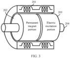
- FIG. 3 is a schematic diagram of an existing hybrid excitation motor.
- a permanent magnet portion 202 and an electric excitation portion 203 in the hybrid excitation motor of the parallel magnetic circuit type are located on a rotating shaft 204 and share an armature winding 201.
- the permanent magnet portion 202 and the electric excitation portion 203 form a main magnetic field of the motor together, to implement regulation and control of an air gap magnetic field of the motor, and improve a speed regulation, drive performance, or voltage regulation protection characteristic of the motor.
- an excitation source is mainly provided by the permanent magnet portion 202, and the electric excitation portion 203 includes an exciting winding 2031.
- An electric excitation circuit 30 obtains a direct current from a power battery pack of an electric vehicle and outputs an excitation current to the exciting winding 2031.
- a value of the excitation current output to the exciting winding 2031 By changing a value of the excitation current output to the exciting winding 2031, a magnetic flux of a main magnetic circuit is enhanced or weakened, thereby implementing a regulation function.
- a balance degree of an electric potential of a bus midpoint of a three-level inverter circuit 10 directly affects many indicators such as withstand voltages and harmonic waves of output currents that are of power devices in the three-level inverter circuit 10.
- the electric potential of the bus midpoint of the three-level inverter circuit 10 can be adjusted in a software control mode that is based on SVPWM, but an adjustment capability of this mode is limited.
- modulation of the three-level inverter circuit 10 is high, and a power factor is low.
- voltage fluctuation of dozens of volts may occur in the electric potential of the bus midpoint. This exceeds an adjustment range of the software control mode, and consequently the electric potential of the bus midpoint cannot be balanced.
- this application provides an electric drive system, an electric excitation circuit, a control method, a powertrain, and an electric vehicle.
- a first input terminal of the electric excitation circuit is connected in parallel to a first bus capacitor, and a second input terminal of the electric excitation circuit is connected in parallel to a second bus capacitor, that is, the electric excitation circuit separately obtains power from the two bus capacitors.
- a controller is configured to: control a working state of the electric excitation circuit to excite an exciting winding of the motor, and control power consumption to be different when the electric excitation circuit obtains power from the two bus capacitors, to balance an electric potential of a bus midpoint.
- connection should be understood in a broad sense.
- a “connection” may be a fixed connection, a detachable connection, or an integrated structure, may be a direct connection, or may be an indirect connection through an intermediary.
- An embodiment of this application provides an electric drive system for a motor, configured to drive a motor having an exciting winding and an electric excitation circuit, such as an electric excitation motor or a hybrid excitation motor.
- FIG. 4 is a schematic diagram of an electric drive system according to an embodiment of this application.
- the electric drive system includes a bus, a three-level inverter circuit 10, an electric excitation circuit 30, and a controller 40.
- the bus includes a positive bus P and a negative bus N.
- An input terminal of the three-level inverter circuit 10 is connected to a power battery pack 60, and an output terminal of the three-level inverter circuit 10 is connected to a motor 20.
- the three-level inverter circuit 10 is configured to convert a direct current supplied by the power battery pack 60 into an alternating current and then supply the alternating current to the motor 20.
- the three-level inverter circuit 10 includes a first bus capacitor C1, a second bus capacitor C2, and a power conversion circuit 101.
- the first bus capacitor C1 is connected between the positive bus P and a bus midpoint O
- the second bus capacitor C2 is connected between the negative bus N and the bus midpoint O.
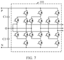
- the three-level inverter circuit 10 is a neutral point clamped (Neutral Point Clamped, NPC) three-level inverter circuit.
- FIG. 5 and FIG. 6 are schematic diagrams of neutral point clamped three-level inverter circuits.
- FIG. 5 is a schematic diagram of the power conversion circuit 101 using a T-shaped connection.
- FIG. 6 is a schematic diagram of a power conversion circuit 101 using an I-shaped connection.
- the three-level inverter circuit 10 may alternatively be an active neutral point clamped (Active Neutral Point Clamped, ANPC) three-level inverter circuit.
- ANPC Active Neutral Point Clamped
- the electric excitation circuit 30 is configured to output an excitation current to an exciting winding 2031.
- a frequency and a value of the excitation current output to the exciting winding 2031 By changing a frequency and a value of the excitation current output to the exciting winding 2031, a magnetic flux of a main magnetic circuit is enhanced or weakened, thereby improving a speed regulation, drive performance, or voltage regulation protection characteristic of the motor.
- a first input terminal of the electric excitation circuit 30 is connected in parallel to the first bus capacitor C1, and a second input terminal of the electric excitation circuit 30 is connected in parallel to the second bus capacitor C2, that is, the electric excitation circuit separately obtains power from the two bus capacitors.
- the excitation current of the exciting winding 2031 is positively correlated with an output torque of the motor, and an offset amplitude of the electric potential of the bus midpoint of the three-level inverter circuit 10 is also positively correlated with the output torque of the motor. Therefore, on a premise of ensuring that the value of the excitation current of the exciting winding 2031 satisfies a current requirement, the controller 40 controls a working state of the electric excitation circuit 30 to make the electric excitation circuit 301 obtain different quantities of electricity from the first bus capacitor C1 and the second bus capacitor C2, thereby balancing the electric potential of the bus midpoint.
- the controller 40 in this embodiment may be an application-specific integrated circuit (Application-Specific Integrated Circuit, ASIC), a programmable logic device (Programmable Logic Device, PLD), a digital signal processor (Digital Signal Processor, DSP), or a combination thereof.
- the PLD may be a complex programmable logic device (Complex Programmable Logic Device, CPLD), a field-programmable gate array (Field-programmable Gate Array, FPGA), a generic array logic (Generic Array Logic, GAL), or any combination thereof. This is not specifically limited in this embodiment of this application.
- the electric excitation circuit 301 includes controllable switching transistors.
- a type of the controllable switching transistor is not specifically limited in this embodiment of this application.
- the controllable switching transistor may be an insulated gate bipolar transistor (Insulated Gate Bipolar Transistor, IGBT), a metal-oxide-semiconductor field-effect transistor (Metal-Oxide-Semiconductor Field-Effect Transistor, MOSFET, which is referred to as a MOS transistor below), or a SiC MOSFET (silicon carbide metal-oxide-semiconductor field-effect transistor, silicon carbide metal-oxide-semiconductor field-effect transistor).
- IGBT Insulated Gate Bipolar Transistor
- MOSFET Metal-Oxide-Semiconductor Field-Effect Transistor
- SiC MOSFET silicon carbide metal-oxide-semiconductor field-effect transistor, silicon carbide metal-oxide-semiconductor field
- the controller 40 may send a control signal to the controllable switching transistors to control working states of the controllable switching transistors.
- the input terminals of the electric excitation circuit in the electric drive system obtain power not from the power battery pack but respectively from the two bus capacitors; and the controller controls the working state of the electric excitation circuit, and makes power consumption different when the electric excitation circuit obtains power from the two bus capacitors, thereby balancing the electric potential of the bus midpoint.
- the controller controls the working state of the electric excitation circuit, and makes power consumption different when the electric excitation circuit obtains power from the two bus capacitors, thereby balancing the electric potential of the bus midpoint.
- no additional equalization circuit needs to be added in this solution.
- the electric potential of the bus midpoint can be balanced even if an offset of the electric potential of the bus midpoint is large.
- a high-voltage power battery pack is usually selected for power supply.
- a power battery pack with an output voltage of 550 V to 850 V is used for power supply.
- input terminals of an electric excitation circuit are directly connected in parallel to a power battery pack, a requirement on withstand voltages of power devices in the electric excitation circuit is high, and power devices that have resistance to a high voltage (a specification of 900 V) and a large current need to be selected during model selection. This leads to difficulties in model selection and design of the power devices and high costs.
- withstand voltages of power devices in each conversion circuit should be approximately half of those in the solution of the conventional technology, so that the switching loss of the power devices is reduced.
- the electric excitation circuit in this application may select power devices with lower withstand voltages (for example, a specification of 650 V), to facilitate a model selection design.
- the electric drive system provided in this application is also convenient to implement a power supply solution by using the high-voltage power battery pack.
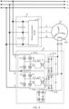
- FIG. 8 is a schematic diagram of another electric drive system according to an embodiment of this application.
- An electric excitation circuit 30 in the electric drive system includes a first excitation circuit and a second excitation circuit.
- An input terminal of the first excitation circuit is a first input terminal of the electric excitation circuit 30.
- the first excitation circuit includes a first LLC resonant conversion circuit 301a and a first rectifier circuit 301b
- the second excitation circuit includes a second LLC resonant conversion circuit 302a and a second rectifier circuit 302b.
- An input terminal of the first LLC resonant conversion circuit 301a is the input terminal of the first excitation circuit, and an output terminal of the first LLC resonant conversion circuit 301a is connected to an input terminal of the first rectifier circuit 301b.
- the illustrated first LLC resonant conversion circuit 301a includes a full-bridge inverter circuit formed by switching transistors S1-S4, a capacitor Cr1, an inductor Lr1, and a first transformer T1.
- An output terminal of the first rectifier circuit 301b is an output terminal of the first excitation circuit.
- An input terminal of the second excitation circuit is a second input terminal of the electric excitation circuit 30.
- An input terminal of the second LLC resonant conversion circuit 302a is the input terminal of the second excitation circuit, and an output terminal of the second LLC resonant conversion circuit 302a is connected to an input terminal of the second rectifier circuit.
- the illustrated second LLC resonant conversion circuit 302a includes a full-bridge inverter circuit formed by switching transistors S5-S8, a capacitor Cr2, an inductor Lr2, and a second transformer T2.
- An output terminal of the second rectifier circuit 302b is an output terminal of the second excitation circuit.
- the output terminal of the first excitation circuit is connected in parallel to the output terminal of the second excitation circuit, and then the two output terminals are connected to an output terminal of the electric excitation circuit 30.
- a controller is configured to control working states of the first LLC resonant conversion circuit 301a and the second LLC resonant conversion circuit 302a. The following provides a detailed description.
- the controller controls working states of the first excitation circuit and the second excitation circuit based on an excitation current needed by an exciting winding and at least one of voltage sampling values of buses and an output current sampling value of a three-level inverter circuit.
- the following first describes a principle of balancing an electric potential of a bus midpoint by using the voltage sampling values of the buses.
- the voltage sampling values of the buses directly represent current voltages of a positive bus and a negative bus.
- a voltage sampling value of the positive bus is different from an absolute value of a voltage sampling value of the negative bus, it indicates that the electric potential of the bus midpoint is imbalanced in this case.
- the controller controls the first LLC resonant conversion circuit and the second LLC resonant conversion circuit to output currents with a same value, and a sum of the two currents is a currently needed excitation current.
- the controller obtains a currently needed excitation current and controls a sum of output currents of the first LLC resonant conversion circuit and the second LLC resonant conversion circuit to be the currently needed excitation current, and an output current of the first LLC resonant conversion circuit is greater than an output current of the second LLC resonant conversion circuit.
- the first LLC resonant conversion circuit obtains more quantity of electricity from a first bus capacitor C1, and then the voltage of the positive bus is made decreased.
- the controller controls the first LLC resonant conversion circuit and the second LLC resonant conversion circuit to output currents with a same value, to balance the electric potential of the bus midpoint.
- the controller obtains a currently needed excitation current and controls a sum of output currents of the first LLC resonant conversion circuit and the second LLC resonant conversion circuit to be the currently needed excitation current, and an output current of the first LLC resonant conversion circuit is less than an output current of the second LLC resonant conversion circuit.
- the second LLC resonant conversion circuit obtains more quantity of electricity from a second bus capacitor C2, and then the absolute value of the voltage of the negative bus is made decreased.
- the controller controls the first LLC resonant conversion circuit and the second LLC resonant conversion circuit to output currents with a same value, to balance the electric potential of the bus midpoint.
- an output voltage of a power battery pack is 750 V
- the voltage sampling values corresponding to the positive bus and the negative bus are equal in this case, and the electric potential of the direct-current bus midpoint is balanced.
- the voltage sampling value of the positive bus is greater than the absolute value of the voltage sampling value of the negative bus, indicating that the voltage of the positive bus is relatively high in this case.
- the controller controls the output current of the first LLC resonant conversion circuit to be greater than the output current of the second LLC resonant conversion circuit, to reduce the voltage of the positive bus.
- the controller controls the output current of the first LLC resonant conversion circuit to be less than the output current of the second LLC resonant conversion circuit, to reduce the voltage of the negative bus (that is, reduce the absolute value of the voltage of the negative bus).
- a deviation threshold may be preset in this embodiment of this application.
- a difference between the voltage sampling value of the positive bus and the absolute value of the voltage sampling value of the negative bus is less than the deviation threshold, it is determined that the electric potential of the direct-current bus midpoint is balanced.
- the difference is greater than or equal to the deviation threshold, it is determined that the electric potential of the bus midpoint is imbalanced.
- the deviation threshold is a small value, and may be determined based on an actual situation. This is not specifically limited in this embodiment of this application. For example, when the deviation threshold indicates that a difference between the voltage of the positive bus and the absolute value of the voltage of the negative bus is less than 3 V, it is determined that the electric potential of the direct-current bus midpoint is balanced.
- the following describes a principle of balancing the electric potential of the bus midpoint by using the output current sampling value of the three-level inverter circuit.
- the output current sampling value of the three-level inverter circuit can represent current voltage statuses of the positive bus and the negative bus. Specifically, a direct current component of the output current is zero when the electric potential of the bus midpoint is balanced. A direct current component of the output current is greater than zero when the voltage of the positive bus is higher than that of the negative bus. A direct current component of the output current is less than zero when the voltage of the positive bus is lower than that of the negative bus.
- the controller may control the working states of the first LLC resonant conversion circuit and the second LLC resonant conversion circuit based on a direct current component of the output current sampling value of the three-level inverter circuit.
- the controller controls the first LLC resonant conversion circuit and the second LLC resonant conversion circuit to output a same current. A sum of the two currents is a currently needed excitation current.
- the controller obtains a currently needed excitation current and controls a sum of output currents of the first LLC resonant conversion circuit and the second LLC resonant conversion circuit to be the currently needed excitation current, and an output current of the first LLC resonant conversion circuit is greater than an output current of the second LLC resonant conversion circuit. Then, the voltage of the positive bus is made decreased. When the voltage of the positive bus decreases to the absolute value of the voltage of the negative bus, the controller controls the first LLC resonant conversion circuit and the second LLC resonant conversion circuit to output currents with a same value.
- the controller obtains a currently needed excitation current and controls a sum of output currents of the first LLC resonant conversion circuit and the second LLC resonant conversion circuit to be the currently needed excitation current, and an output current of the first LLC resonant conversion circuit is less than an output current of the second LLC resonant conversion circuit. Then, the absolute value of the voltage of the negative bus is made decreased. When the absolute value of the voltage of the negative bus decreases to the voltage of the positive bus, the controller controls the first LLC resonant conversion circuit and the second LLC resonant conversion circuit to output currents with a same value.
- a deviation range may be preset in this embodiment of this application.
- the direct current component of the output current sampling value falls within the deviation range, it is determined that the electric potential of the direct-current bus midpoint is balanced.
- the direct current component of the output current sampling value exceeds the deviation range, it is determined that the electric potential of the bus midpoint is imbalanced.
- the deviation range is a small range, and may be determined based on an actual situation. This is not specifically limited in this embodiment of this application.
- the controller may use either of the foregoing two manners as a criterion, or may also use both the foregoing two manners as a criterion.
- the controller starts to adjust output power of the two conversion circuits.
- the controller starts to adjust output power of the two conversion circuits.
- the controller adjusts switching frequencies of control signals of the first excitation circuit and the second excitation circuit to adjust output currents of the first excitation circuit and the second excitation circuit.
- a value of the output current of the first excitation circuit is positively correlated with the positive bus and an offset amplitude of the electric potential of the bus midpoint
- a value of the output current of the second excitation circuit is positively correlated with the negative bus and the offset amplitude of the electric potential of the bus midpoint. This can balance the electric potential of the bus midpoint quickly when an offset exists in the electric potential of the bus midpoint.
- the first rectifier circuit 301b and the second rectifier circuit 302b are full-bridge rectifier circuits.
- power devices included in the first rectifier circuit 301b and the second rectifier circuit 302b are diodes.
- power devices included in the first rectifier circuit 301b and the second rectifier circuit 302b are controllable switching transistors.
- the controller controls working states of the controllable switching transistors to adjust output currents of the first rectifier circuit 301b and the second rectifier circuit 302b.
- the controller may further control a working state of the three-level inverter circuit 10, that is, the controller and a controller of the three-level inverter circuit 10 may be integrated with each other.
- the first excitation circuit and the second excitation circuit of the electric excitation circuit respectively obtain power from the two bus capacitors; and the controller controls the working states of the first excitation circuit and the second excitation circuit, and makes power consumption different when the electric excitation circuit obtains power from the two bus capacitors, thereby balancing the electric potential of the bus midpoint.
- the electric potential of the bus midpoint can be balanced even if an offset of the electric potential of the bus midpoint is large.
- withstand voltages of power devices the controllable switching transistors S1-S8 in the first excitation circuit and the second excitation circuit should be approximately half of those in the solution of the conventional technology, so that a switching loss of the power devices is reduced.
- the electric excitation circuit in this application may choose to use power devices with lower withstand voltages, to facilitate a model selection design.
- a high-voltage power battery pack is usually selected for power supply.
- the electric drive system provided in this application is also more convenient to implement a power supply solution by using the high-voltage power battery pack.
- FIG. 9 is a schematic diagram of still another electric drive system according to an embodiment of this application.
- the electric excitation circuit includes a first excitation circuit, a second excitation circuit, and a third rectifier circuit 303.
- An input terminal of the first excitation circuit is a first input terminal of the electric excitation circuit 30.
- the first excitation circuit includes a first LLC resonant conversion circuit 301a, and specifically includes a full-bridge inverter circuit formed by switching transistors S1-S4, a capacitor Cr1, an inductor Lr1, and one primary-side winding of a third transformer T3.
- An input terminal of the second excitation circuit is a second input terminal of the electric excitation circuit 30.
- the second excitation circuit includes a second LLC resonant conversion circuit 302a, and specifically includes a full-bridge inverter circuit formed by switching transistors S5-S8, a capacitor Cr2, an inductor Lr2, and the other primary-side winding of the third transformer T3.
- Primary-side windings of the first LLC resonant conversion circuit 301a and the second LLC resonant conversion circuit 302a have a same dotted terminal and a same quantity of coil turns and share a magnetic core of the third transformer T3, and a secondary-side winding of the third transformer T3 is connected to the third rectifier circuit 303.
- Resonance frequencies of the first LLC resonant conversion circuit 301a and the second LLC resonant conversion circuit 302a are equal.
- An output terminal of the third rectifier circuit 303 is an output terminal of the electric excitation circuit.
- the following describes a control principle of a controller.
- the controller controls working states of the first LLC resonant conversion circuit 301a and the second LLC resonant conversion circuit 302a based on a same control signal.
- the electric excitation circuit 30 can implement independent voltage balancing.
- the two primary-side windings of the third transformer T3 have the same dotted terminal and share the magnetic core, that is, the windings are in a forward transformer relationship. Therefore, there is an energy exchange between the two LLC resonant conversion circuits. Energy is transferred from an LLC resonant conversion circuit with a higher input voltage to an LLC resonant conversion circuit with a lower input voltage.
- the controller adjusts a switching frequency of the control signal based on an excitation current needed by an exciting winding.
- the third rectifier circuit 303 is a full-bridge rectifier circuit.
- power devices included in the third rectifier circuit 303 are diodes.
- power devices included in the third rectifier circuit 303 are controllable switching transistors.
- the controller controls working states of the controllable switching transistors to adjust an output current of the third rectifier circuit 303.
- the controller may further control a working state of a three-level inverter circuit 10, that is, the controller and a controller of the three-level inverter circuit 10 may be integrated with each other.
- the first excitation circuit and the second excitation circuit of the electric excitation circuit respectively obtain power from two bus capacitors; and the controller controls the first excitation circuit and the second excitation circuit based on the same control signal, so that there is an energy exchange between the two LLC resonant conversion circuits, thereby implementing independent voltage balancing regulation.
- the electric excitation circuit By multiplexing the electric excitation circuit, no additional equalization circuit needs to be added in this solution.
- the electric potential of the bus midpoint can be balanced even if an offset of the electric potential of the bus midpoint is large.
- withstand voltages of power devices the controllable switching transistors S1-S8 in the first excitation circuit and the second excitation circuit should be approximately half of those in the solution of the conventional technology, so that a switching loss of the power devices is reduced.
- the electric excitation circuit in this application may choose to use power devices with lower withstand voltages, to facilitate a model selection design.
- a high-voltage power battery pack is usually selected for power supply.
- the electric drive system provided in this application is also more convenient to implement a power supply solution by using the high-voltage power battery pack.
- an embodiment of this application further provides a control method applied to the electric drive system.
- a control method applied to the electric drive system For a specific implementation and a working principle of the electric drive system, reference may be made to descriptions in the foregoing embodiments. Details are not described in this embodiment of this application again.
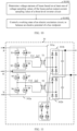
- FIG. 10 is a flowchart of a control method for an electric drive system according to an embodiment of this application.
- the illustrated method includes the following steps:
- S1001 Determine voltage statuses of buses based on at least one of voltage sampling values of the buses and an output current sampling value of a three-level inverter circuit.
- the voltage sampling values of the buses directly represent current voltages of a positive bus and a negative bus.
- a voltage sampling value of the positive bus is different from an absolute value of a voltage sampling value of the negative bus, it indicates that an electric potential of a bus midpoint is imbalanced in this case.
- the output current sampling value of the three-level inverter circuit can represent current voltage statuses of the positive bus and the negative bus. Specifically, a direct current component of the output current is zero when the electric potential of the bus midpoint is balanced. A direct current component of the output current is greater than zero when the voltage of the positive bus is higher than that of the negative bus. A direct current component of the output current is less than zero when the voltage of the positive bus is lower than that of the negative bus.
- the electric excitation circuit includes a first excitation circuit and a second excitation circuit.
- the first excitation circuit obtains power from a first bus capacitor
- the second excitation circuit obtains power from a second bus capacitor.
- the first excitation circuit includes a first LLC resonant conversion circuit
- the second excitation circuit includes a second LLC resonant conversion circuit.
- output terminals of the first excitation circuit and the second excitation circuit are connected in parallel.
- the following describes a method for balancing the electric potential of the bus midpoint by using the voltage sampling values of the buses.
- the first LLC resonant conversion circuit and the second LLC resonant conversion circuit are controlled to output currents with a same value, and a sum of the two currents is a currently needed excitation current.
- the voltage sampling value of the positive bus is greater than the absolute value of the voltage sampling value of the negative bus, it indicates that the voltage of the positive bus is greater than an absolute value of the voltage of the negative bus in this case.
- a currently needed excitation current is obtained and a sum of output currents of the first LLC resonant conversion circuit and the second LLC resonant conversion circuit is controlled to be the currently needed excitation current, and an output current of the first LLC resonant conversion circuit is greater than an output current of the second LLC resonant conversion circuit.
- the first LLC resonant conversion circuit obtains more quantity of electricity from the first bus capacitor C1, and then the voltage of the positive bus is made decreased.
- the first LLC resonant conversion circuit and the second LLC resonant conversion circuit are controlled to output currents with a same value.
- the voltage sampling value of the positive bus is less than the absolute value of the voltage sampling value of the negative bus, it indicates that the voltage of the positive bus is less than an absolute value of the voltage of the negative bus in this case.
- a currently needed excitation current is obtained and a sum of output currents of the first LLC resonant conversion circuit and the second LLC resonant conversion circuit is controlled to be the currently needed excitation current, and an output current of the first LLC resonant conversion circuit is less than an output current of the second LLC resonant conversion circuit.
- the second LLC resonant conversion circuit obtains more quantity of electricity from the second bus capacitor C2, and then the absolute value of the voltage of the negative bus is made decreased.
- the absolute value of the voltage of the negative bus decreases to the voltage of the positive bus, the first LLC resonant conversion circuit and the second LLC resonant conversion circuit are controlled to output currents with a same value.
- the following describes a method for balancing the electric potential of the bus midpoint by using the output current sampling value of the three-level inverter circuit.
- the first LLC resonant conversion circuit and the second LLC resonant conversion circuit are controlled to output a same current.
- a sum of the two currents is a currently needed excitation current.
- the electric excitation circuit uses the implementation shown in FIG. 9 .
- Working states of the first LLC resonant conversion circuit and the second LLC resonant conversion circuit are controlled based on a same control signal.
- the electric excitation circuit can implement independent voltage balancing.
- the two primary-side windings of the third transformer T3 have the same dotted terminal and share the magnetic core, that is, the windings are in a forward transformer relationship. Therefore, there is an energy exchange between the two LLC resonant conversion circuits. Energy is transferred from an LLC resonant conversion circuit with a higher input voltage to an LLC resonant conversion circuit with a lower input voltage.
- the electric potential of the bus midpoint is balanced by using the control method provided in this embodiment of this application.
- withstand voltages of power devices in each conversion circuit should be approximately half of those in the solution of the conventional technology, so that a switching loss of the power devices is reduced.
- the electric excitation circuit in this application may select power devices with lower withstand voltages, to facilitate a model selection design.
- An embodiment of this application further provides an electric excitation circuit applied to the electric drive system in the foregoing embodiments.
- the electric excitation circuit is configured to output an excitation current to an exciting winding.
- the electric excitation circuit includes a first input terminal, a second input terminal, a third input terminal, an output terminal, and a control terminal.
- the first input terminal is connected to a positive bus of the electric drive system
- the second input terminal is connected to a bus midpoint
- the third input terminal is connected to a negative bus of the electric drive system.
- the output terminal is connected to the exciting winding of a motor, and is configured to output the excitation current to the exciting winding.
- the control terminal is configured to receive a control signal.
- the electric excitation circuit is configured to balance an electric potential of the bus midpoint under the control of the control signal.
- FIG. 11 is a schematic diagram of an electric excitation circuit according to an embodiment of this application.
- the illustrated electric excitation circuit 30 includes a first excitation circuit and a second excitation circuit.
- a first port P of an input terminal of the first excitation circuit is the first input terminal, and a second port O of the input terminal of the first excitation circuit is the second input terminal.
- a first port N of an input terminal of the second excitation circuit is the third input terminal, and the second port O of the input terminal of the first excitation circuit is the second input terminal.
- An output terminal of the first excitation circuit is connected in parallel to an output terminal of the second excitation circuit, and then the two output terminals are connected to the output terminal of the electric excitation circuit.
- An input terminal of a first LLC resonant conversion circuit 301a is the input terminal of the first excitation circuit, and an output terminal of the first LLC resonant conversion circuit 301a is connected to an input terminal of a first rectifier circuit 301b.
- the illustrated first LLC resonant conversion circuit 301a includes a full-bridge inverter circuit formed by switching transistors S1-S4, a capacitor Cr1, an inductor Lr1, and a first transformer T1.
- An output terminal of the first rectifier circuit 301b is the output terminal of the first excitation circuit.
- An input terminal of a second LLC resonant conversion circuit 302a is the input terminal of the second excitation circuit, and an output terminal of the second LLC resonant conversion circuit 302a is connected to an input terminal of a second rectifier circuit 302b.
- the illustrated second LLC resonant conversion circuit 302a includes a full-bridge inverter circuit formed by switching transistors S5-S8, a capacitor Cr2, an inductor Lr2, and a second transformer T2.
- An output terminal of the second rectifier circuit 302b is the output terminal of the second excitation circuit.
- FIG. 12 is a schematic diagram of another electric excitation circuit according to an embodiment of this application.
- the electric excitation circuit includes a first excitation circuit, a second excitation circuit, and a third rectifier circuit 303.
- a first port P of an input terminal of the first excitation circuit is the first input terminal, and a second port O of the input terminal of the first excitation circuit is the second input terminal.
- the first excitation circuit includes a first LLC resonant conversion circuit 301a, and specifically includes a full-bridge inverter circuit formed by switching transistors S1-S4, a capacitor Cr1, an inductor Lr1, and one primary-side winding of a third transformer T3.
- a first port N of an input terminal of the second excitation circuit is the third input terminal, and the second port O of the input terminal of the first excitation circuit is the second input terminal.
- the second excitation circuit includes a second LLC resonant conversion circuit 302a, and specifically includes a full-bridge inverter circuit formed by switching transistors S5-S8, a capacitor Cr2, an inductor Lr2, and the other primary-side winding of the third transformer T3.
- Primary-side windings of the first LLC resonant conversion circuit 301a and the second LLC resonant conversion circuit 302a have a same dotted terminal and a same quantity of coil turns and share a magnetic core of the third transformer T3, and a secondary-side winding of the third transformer T3 is connected to the third rectifier circuit 303.
- Resonance frequencies of the first LLC resonant conversion circuit 301a and the second LLC resonant conversion circuit 302a are equal.
- An output terminal of the third rectifier circuit 303 is an output terminal of the electric excitation circuit 30.
- the input terminals of the electric excitation circuit obtain power not from a power battery pack but respectively from two bus capacitors.
- a working state of the electric excitation circuit is controlled, and power consumption may be made different when the electric excitation circuit obtains power from the two bus capacitors, thereby balancing the electric potential of the bus midpoint.
- the electric potential of the bus midpoint can be balanced even if an offset of the electric potential of the bus midpoint is large.
- withstand voltages of power devices in the electric excitation circuit should be approximately half of those in the solution of the conventional technology, so that a switching loss of the power devices is reduced.
- the electric excitation circuit may choose to use power devices with lower withstand voltages, to facilitate a model selection design.
- an embodiment of this application further provides a powertrain of an electric vehicle.
- the following provides a description with reference to the accompanying drawings.
- FIG. 13 is a schematic diagram of a powertrain of an electric vehicle according to an embodiment of this application.
- the powertrain 1300 includes an electric drive system 1301 and a motor 20.
- the electric drive system 1301 includes a bus, a three-level inverter circuit, an electric excitation circuit, and a controller.
- the motor 20 may be an electric excitation motor or a hybrid excitation motor, and the motor 20 includes an exciting winding.
- the motor 20 is connected to an output terminal of the three-level inverter circuit, and is configured to convert electrical energy into mechanical energy to drive the electric vehicle.
- the powertrain provided in this embodiment of this application includes the electric drive system, input terminals of the electric excitation circuit in the electric drive system respectively obtain power from two bus capacitors; and the controller controls a working state of the electric excitation circuit, and makes power consumption different when the electric excitation circuit obtains power from the two bus capacitors, thereby balancing an electric potential of a bus midpoint.
- the electric potential of the bus midpoint can be balanced even if an offset of the electric potential of the bus midpoint is large. Therefore, the powertrain can take full advantage of the three-level electric drive system, effectively improve efficiency of the electric drive system, reduce output voltage harmonic waves, and optimize electromagnetic interference performance.
- a high-voltage power battery pack is usually selected for power supply.
- the powertrain provided in this application is also convenient to implement a power supply solution by using the high-voltage power battery pack.
- an embodiment of this application further provides an electric vehicle.
- the following provides a detailed description with reference to the accompanying drawings.
- FIG. 14 is a schematic diagram of an electric vehicle according to an embodiment of this application.
- the electric vehicle 1400 includes a power battery pack 1401 and a powertrain 1300.
- the power battery pack 1401 is configured to provide a needed direct current power supply for the powertrain 1300.
- the powertrain 1300 includes an electric drive system and a hybrid excitation motor.
- the electric drive system includes a bus, a three-level inverter circuit, an electric excitation circuit, and a controller.
- the electric vehicle includes the electric drive system provided in the foregoing embodiments, input terminals of the electric excitation circuit in the electric drive system respectively obtain power from two bus capacitors; and the controller controls a working state of the electric excitation circuit, and makes power consumption different when the electric excitation circuit obtains power from the two bus capacitors, thereby balancing an electric potential of a bus midpoint.
- the electric potential of the bus midpoint can be balanced even if an offset of the electric potential of the bus midpoint is large.
- a high-voltage power battery pack is usually selected for power supply.
- the powertrain provided in this application is also convenient to implement a power supply solution by using the high-voltage power battery pack.
- At least one (item) means one or more, and "a plurality of” means two or more.
- a term “and/or” is used to describe an association relationship between associated objects, and represents that three relationships may exist.
- a and/or B may represent the following three cases: Only A exists, only B exists, and both A and B exist, where A and B may be singular or plural.
- a character “/” usually represents an "or” relationship between associated objects.
- At least one of the following items (pieces) or a similar expression thereof indicates any combination of these items, including a single item (piece) or any combination of a plurality of items (pieces).
- At least one item (piece) of a, b, or c may represent a, b, c, "a and b", “a and c", “b and c", or "a, b, and c", where a, b, and c each may be in a singular or plural form.
Landscapes
- Engineering & Computer Science (AREA)
- Power Engineering (AREA)
- Transportation (AREA)
- Mechanical Engineering (AREA)
- Electric Propulsion And Braking For Vehicles (AREA)
- Inverter Devices (AREA)
Abstract
Description
- This application claims the priority to
China Patent Application No. 202011133767.3, filed with the China National Intellectual Property Administration on October 21, 2020 - This application relates to the field of power electronics technologies, and in particular, to an electric drive system, a control method, an electric excitation circuit, a powertrain, and an electric vehicle.
- With aggravation of an energy shortage and environmental pollution in the modern society, as new energy vehicles, electric vehicles have attracted extensive attention from all walks of life. Because an electric drive system of an electric vehicle directly affects safety and efficiency of the electric vehicle, the electric drive system keeps being a hot research topic.
- Compared with a conventional two-level electric drive system, a three-level electric drive system can effectively improve New European Driving Cycle (NEDC) efficiency of the electric drive system, reduce output voltage harmonic waves, and optimize electromagnetic interference performance. Therefore, the three-level electric drive system has gradually become a research object.
-
FIG. 1 is a schematic diagram of an existing three-level inverter circuit. - The three-
level inverter circuit 10 is configured to convert a direct current supplied by a power battery pack into an alternating current and then supply the alternating current to amotor 20. A balance degree of an electric potential of a bus midpoint (a point O in the figure) of the three-level inverter circuit 10 directly affects performance of a three-level electric drive system. Therefore, it is crucial to balancing the electric potential of the bus midpoint. - In the conventional technology, the electric potential of the bus midpoint of the three-
level inverter circuit 10 can be adjusted in a software control mode that is based on SVPWM (Space Vector Pulse-Width Modulation), but an adjustment capability of this mode is limited. When an offset of the electric potential of the bus midpoint is large, it is difficult to balance the electric potential of the bus midpoint. - This application provides an electric drive system, a control method, an electric excitation circuit, a powertrain, and an electric vehicle, to improve a capability of adjusting an electric potential of a bus midpoint.
- According to a first aspect, this application provides an electric drive system. An input terminal of the electric drive system is connected to a power battery pack of an electric vehicle to drive a motor. The motor is an electric excitation motor or a hybrid excitation motor, and the motor includes an exciting winding. The electric drive system includes a bus, a three-level inverter circuit, an electric excitation circuit, and a controller. The bus includes a positive bus and a negative bus. The three-level inverter circuit includes a first bus capacitor and a second bus capacitor. The first bus capacitor is connected between the positive bus and a bus midpoint, and the second bus capacitor is connected between the negative bus and the bus midpoint. A first input terminal of the electric excitation circuit is connected in parallel to the first bus capacitor, a second input terminal of the electric excitation circuit is connected in parallel to the second bus capacitor, and an output terminal of the electric excitation circuit is connected to the exciting winding. The controller is configured to control a working state of the electric excitation circuit, to balance an electric potential of the bus midpoint.
- The input terminals of the electric excitation circuit in the electric drive system respectively obtain power from the two bus capacitors. The controller controls the working state of the electric excitation circuit to excite the exciting winding of the motor, and controls power consumption to be different when the electric excitation circuit obtains power from the two bus capacitors, to balance the electric potential of the bus midpoint. By multiplexing the electric excitation circuit, no additional equalization circuit needs to be added in this solution. In addition, the electric potential of the bus midpoint can be balanced even if an offset of the electric potential of the bus midpoint is large.
- Moreover, when an existing electric excitation circuit directly obtains power from the power battery pack, a requirement on withstand voltages of power devices in the electric excitation circuit is high, which leads to a difficulty in model selection and high costs. In contrast, in this solution of this application, power is separately obtained from the two bus capacitors, and it is required that withstand voltages of power devices in the electric excitation circuit should be approximately half of those in the solution of the conventional technology, so that a switching loss of the power devices is reduced. At same output power, the electric excitation circuit in this application may choose to use power devices with lower withstand voltages, to facilitate a model selection design. Furthermore, when a volume of the power battery pack remains unchanged, currently, to increase a distance per charge of the electric vehicle to the utmost, a high-voltage power battery pack is usually selected for power supply. The electric drive system provided in this application is also more convenient to implement a power supply solution by using the high-voltage power battery pack.
- With reference to the first aspect, in a first possible implementation, the electric excitation circuit includes a first excitation circuit and a second excitation circuit. An input terminal of the first excitation circuit is the first input terminal of the electric excitation circuit, and an input terminal of the second excitation circuit is the second input terminal of the electric excitation circuit. The two excitation circuits respectively obtain power from the two bus capacitors.
- With reference to the first aspect, in a second possible implementation, an output terminal of the first excitation circuit is connected in parallel to an output terminal of the second excitation circuit, and then the two output terminals are connected to the output terminal of the electric excitation circuit, to output an excitation current to the exciting winding. The controller controls working states of the first excitation circuit and the second excitation circuit based on an excitation current needed by the exciting winding and at least one of voltage sampling values of the buses and an output current sampling value of the three-level inverter circuit.
- The voltage sampling values of the buses directly represent current voltages of the positive bus and the negative bus. When an absolute value of a voltage sampling value of the positive bus is different from that of a voltage sampling value of the negative bus, it indicates that the electric potential of the bus midpoint is imbalanced in this case.
- The output current sampling value of the three-level inverter circuit can represent current voltage statuses of the positive bus and the negative bus. A direct current component of the output current is zero when the electric potential of the bus midpoint is balanced. A direct current component of the output current is greater than zero when the voltage of the positive bus is higher than that of the negative bus. A direct current component of the output current is less than zero when the voltage of the positive bus is lower than that of the negative bus.
- With reference to the first aspect, in a third possible implementation, the controller adjusts switching frequencies of control signals of the first excitation circuit and the second excitation circuit to adjust output currents of the first excitation circuit and the second excitation circuit. A value of the output current of the first excitation circuit is positively correlated with the positive bus and an offset amplitude of the electric potential of the bus midpoint, and a value of the output current of the second excitation circuit is positively correlated with the negative bus and the offset amplitude of the electric potential of the bus midpoint.
- For the hybrid excitation motor, the excitation current needed by the exciting winding is positively correlated with an output torque of the motor, and an offset amplitude of the electric potential of the bus midpoint of the three-level inverter circuit is also positively correlated with the output torque of the motor. Therefore, on a premise of ensuring that a value of the excitation current of the exciting winding satisfies a current requirement, a higher offset amplitude of an electric potential of an input terminal of an excitation circuit indicates a larger output current of the excitation circuit, to consume more quantity of electricity, thereby balancing the electric potential of the bus midpoint.
- With reference to the first aspect, in a fourth possible implementation, the first excitation circuit includes a first LLC resonant conversion circuit and a first rectifier circuit, and the second excitation circuit includes a second LLC resonant conversion circuit and a second rectifier circuit. An input terminal of the first LLC resonant conversion circuit is the input terminal of the first excitation circuit, an output terminal of the first LLC resonant conversion circuit is connected to an input terminal of the first rectifier circuit, and an output terminal of the first rectifier circuit is the output terminal of the first excitation circuit. An input terminal of the second LLC resonant conversion circuit is the input terminal of the second excitation circuit, an output terminal of the second LLC resonant conversion circuit is connected to an input terminal of the second rectifier circuit, and an output terminal of the second rectifier circuit is the output terminal of the second excitation circuit. The controller controls working states of the first LLC resonant conversion circuit and the second LLC resonant conversion circuit.
- With reference to the first aspect, in a fifth possible implementation, the first rectifier circuit and the second rectifier circuit include controllable switching transistors, and the controller controls working states of the controllable switching transistors to adjust output currents of the first rectifier circuit and the second rectifier circuit.
- With reference to the first aspect, in a sixth possible implementation, the electric excitation circuit further includes a third rectifier circuit, the first excitation circuit includes a first LLC resonant conversion circuit, and the second excitation circuit includes a second LLC resonant conversion circuit. Primary-side windings of the first LLC resonant conversion circuit and the second LLC resonant conversion circuit have a same dotted terminal and a same quantity of coil turns and share a magnetic core of one transformer, and a secondary-side winding of the transformer is connected to the third rectifier circuit. Resonance frequencies of the first LLC resonant conversion circuit and the second LLC resonant conversion circuit are equal. An output terminal of the third rectifier circuit is the output terminal of the electric excitation circuit.
- With reference to the first aspect, in a seventh possible implementation, the controller controls working states of the first LLC resonant conversion circuit and the second LLC resonant conversion circuit based on a same control signal. In this case, the two primary-side windings of the transformer have the same dotted terminal and share the magnetic core, that is, the windings are in a forward transformer relationship. Therefore, there is an energy exchange between the two LLC resonant conversion circuits. Energy is transferred from an LLC resonant conversion circuit with a higher input voltage to an LLC resonant conversion circuit with a lower input voltage, thereby balancing the electric potential of the bus midpoint.
- With reference to the first aspect, in an eighth possible implementation, the controller adjusts a switching frequency of the control signal based on an excitation current needed by the exciting winding.
- With reference to the first aspect, in a ninth possible implementation, the third rectifier circuit includes controllable switching transistors, and the controller controls working states of the controllable switching transistors to adjust an output current of the third rectifier circuit.
- With reference to the first aspect, in a tenth possible implementation, the controller is further configured to control a working state of the three-level inverter circuit, that is, the controller and a controller of the three-level inverter circuit may be integrated with each other.
- According to a second aspect, this application further provides a control method for an electric drive system. The method includes: determining voltage statuses of buses based on at least one of voltage sampling values of the buses and an output current sampling value of a three-level inverter circuit; and controlling a working state of an electric excitation circuit, to balance an electric potential of a bus midpoint.
- According to a third aspect, this application further provides an electric excitation circuit. The electric excitation circuit includes a first input terminal, a second input terminal, a third input terminal, an output terminal, and a control terminal. The first input terminal is connected to a positive bus of an electric drive system, the second input terminal is connected to a bus midpoint, and the third input terminal is connected to a negative bus of the electric drive system. The output terminal is connected to an exciting winding of a motor, and is configured to output an excitation current to the exciting winding. The control terminal is configured to receive a control signal. The electric excitation circuit is configured to balance an electric potential of the bus midpoint under the control of the control signal.
- With reference to the third aspect, in a first possible implementation, the electric excitation circuit includes a first excitation circuit and a second excitation circuit. A first port of an input terminal of the first excitation circuit is the first input terminal, and a second port of the input terminal of the first excitation circuit is the second input terminal. A first port of an input terminal of the second excitation circuit is the third input terminal, and the second port of the input terminal of the first excitation circuit is the second input terminal.
- With reference to the third aspect, in a second possible implementation, an output terminal of the first excitation circuit is connected in parallel to an output terminal of the second excitation circuit, and then the two output terminals are connected to the output terminal of the electric excitation circuit.
- With reference to the third aspect, in a third possible implementation, the first excitation circuit includes a first LLC resonant conversion circuit and a first rectifier circuit, and the second excitation circuit includes a second LLC resonant conversion circuit and a second rectifier circuit. An input terminal of the first LLC resonant conversion circuit is the input terminal of the first excitation circuit, an output terminal of the first LLC resonant conversion circuit is connected to an input terminal of the first rectifier circuit, and an output terminal of the first rectifier circuit is the output terminal of the first excitation circuit. An input terminal of the second LLC resonant conversion circuit is the input terminal of the second excitation circuit, an output terminal of the second LLC resonant conversion circuit is connected to an input terminal of the second rectifier circuit, and an output terminal of the second rectifier circuit is the output terminal of the second excitation circuit.
- With reference to the third aspect, in a fourth possible implementation, the electric excitation circuit further includes a third rectifier circuit, the first excitation circuit includes a first LLC resonant conversion circuit, and the second excitation circuit includes a second LLC resonant conversion circuit. Primary-side windings of the first LLC resonant conversion circuit and the second LLC resonant conversion circuit have a same dotted terminal and a same quantity of coil turns and share a magnetic core of one transformer, and a secondary-side winding of the transformer is connected to the third rectifier circuit. Resonance frequencies of the first LLC resonant conversion circuit and the second LLC resonant conversion circuit are equal. An output terminal of the third rectifier circuit is the output terminal of the electric excitation circuit.
- According to a fourth aspect, this application further provides a powertrain. The powertrain includes the electric drive system provided above and further includes a motor. The motor is an electric excitation motor or a hybrid excitation motor. The motor is connected to an output terminal of a three-level inverter circuit. The motor is configured to convert electrical energy into mechanical energy to drive an electric vehicle.
- According to a fifth aspect, this application further provides an electric vehicle. The electric vehicle includes the powertrain and the power battery pack that are provided above. The power battery pack is configured to provide a needed direct current power supply for the powertrain.
-
-
FIG. 1 is a schematic diagram of an existing three-level inverter circuit; -
FIG. 2 is a schematic diagram of a three-level electric drive system corresponding toFIG. 1 ; -
FIG. 3 is a schematic diagram of an existing hybrid excitation motor; -
FIG. 4 is a schematic diagram of an electric drive system according to an embodiment of this application; -
FIG. 5 is a schematic diagram of a neutral point clamped three-level inverter circuit; -
FIG. 6 is a schematic diagram of another neutral point clamped three-level inverter circuit; -
FIG. 7 is a schematic diagram of an active neutral point clamped three-level inverter circuit; -
FIG. 8 is a schematic diagram of another electric drive system according to an embodiment of this application; -
FIG. 9 is a schematic diagram of still another electric drive system according to an embodiment of this application; -
FIG. 10 is a flowchart of a control method for an electric drive system according to an embodiment of this application; -
FIG. 11 is a schematic diagram of an electric excitation circuit according to an embodiment of this application; -
FIG. 12 is a schematic diagram of another electric excitation circuit according to an embodiment of this application; -
FIG. 13 is a schematic diagram of a powertrain of an electric vehicle according to an embodiment of this application; and -
FIG. 14 is a schematic diagram of an electric vehicle according to an embodiment of this application. - To make a person skilled in the art better understand technical solutions provided in embodiments of this application, the following first describes an application scenario of an electric drive system provided in this application.
-
FIG. 2 is a schematic diagram of a three-level electric drive system corresponding toFIG. 1 . - The three-level electric drive system uses a three-
level conversion converter 10 to convert a direct current supplied by a power battery pack into an alternating current and then supply the alternating current to amotor 20. - The
motor 20 is a hybrid excitation motor or an electric excitation motor, and themotor 20 includes an exciting winding 2031. When themotor 20 works, anelectric excitation circuit 30 outputs an excitation current to the exciting winding 2031. - The following uses an example for detailed description in which the
motor 20 is a hybrid excitation motor. - The hybrid excitation motor suitably incorporates two excitation modes, namely, permanent magnet excitation and electric excitation, properly changes a topology structure of the motor, maximizes advantages of the two excitation modes and overcomes their respective disadvantages. This maintains high efficiency and power density of the electric drive system, and enables the electric drive system to have adjustable excitation, a wide speed regulation range, and other characteristics.
- Based on interaction relationships between magnetic potentials of permanent magnets and magnetic potentials of electric excitation in hybrid excitation motors, the hybrid excitation motors may usually be classified into three types: a series magnetic circuit type, a parallel magnetic circuit type, and a series-parallel hybrid magnetic circuit type. For the series magnetic circuit type, the magnetic potential of the permanent magnet is connected in series to the magnetic potential generated by the electric excitation, to form an air gap magnetic field together. For the parallel magnetic circuit type, there is usually a radial magnetic circuit and an axial magnetic circuit, and a magnetic circuit of a permanent magnet and a magnetic circuit of electric excitation are independent of each other but interact with each other in an air gap to form a main magnetic field of the motor together. For the series-parallel hybrid magnetic circuit type, a magnetic circuit of a permanent magnet and a magnetic circuit of electric excitation have both a series part and a parallel part, and form a main magnetic field of the motor together.
- The following uses a hybrid excitation motor of the parallel magnetic circuit type as an example for description.
-
FIG. 3 is a schematic diagram of an existing hybrid excitation motor. - A
permanent magnet portion 202 and anelectric excitation portion 203 in the hybrid excitation motor of the parallel magnetic circuit type are located on arotating shaft 204 and share an armature winding 201. - In the hybrid excitation motor of the parallel structure, the
permanent magnet portion 202 and theelectric excitation portion 203 form a main magnetic field of the motor together, to implement regulation and control of an air gap magnetic field of the motor, and improve a speed regulation, drive performance, or voltage regulation protection characteristic of the motor. To inherit an advantage of high efficiency of a permanent magnet motor to the utmost, an excitation source is mainly provided by thepermanent magnet portion 202, and theelectric excitation portion 203 includes an exciting winding 2031. - An
electric excitation circuit 30 obtains a direct current from a power battery pack of an electric vehicle and outputs an excitation current to the exciting winding 2031. By changing a value of the excitation current output to the exciting winding 2031, a magnetic flux of a main magnetic circuit is enhanced or weakened, thereby implementing a regulation function. - A balance degree of an electric potential of a bus midpoint of a three-
level inverter circuit 10 directly affects many indicators such as withstand voltages and harmonic waves of output currents that are of power devices in the three-level inverter circuit 10. In the conventional technology, the electric potential of the bus midpoint of the three-level inverter circuit 10 can be adjusted in a software control mode that is based on SVPWM, but an adjustment capability of this mode is limited. - For example, in some scenarios, modulation of the three-
level inverter circuit 10 is high, and a power factor is low. In this case, voltage fluctuation of dozens of volts may occur in the electric potential of the bus midpoint. This exceeds an adjustment range of the software control mode, and consequently the electric potential of the bus midpoint cannot be balanced. - When the motor driven by the electric drive system is an electric excitation motor, the foregoing problem also exists. Details are not described in this embodiment of this application again.
- To resolve the foregoing problem in the conventional technology, this application provides an electric drive system, an electric excitation circuit, a control method, a powertrain, and an electric vehicle. A first input terminal of the electric excitation circuit is connected in parallel to a first bus capacitor, and a second input terminal of the electric excitation circuit is connected in parallel to a second bus capacitor, that is, the electric excitation circuit separately obtains power from the two bus capacitors. A controller is configured to: control a working state of the electric excitation circuit to excite an exciting winding of the motor, and control power consumption to be different when the electric excitation circuit obtains power from the two bus capacitors, to balance an electric potential of a bus midpoint. By multiplexing the electric excitation circuit, no additional equalization circuit needs to be added in this solution. In addition, the electric potential of the bus midpoint can be balanced even if an offset of the electric potential of the bus midpoint is large.
- Terms such as "first" and "second" in descriptions of this application are merely intended for a purpose of description, and shall not be understood as an indication or implication of relative importance or implicit indication of a quantity of indicated technical features.
- In this application, unless otherwise clearly specified and limited, a term "connection" should be understood in a broad sense. For example, a "connection" may be a fixed connection, a detachable connection, or an integrated structure, may be a direct connection, or may be an indirect connection through an intermediary.
- An embodiment of this application provides an electric drive system for a motor, configured to drive a motor having an exciting winding and an electric excitation circuit, such as an electric excitation motor or a hybrid excitation motor. The following provides a detailed description with reference to the accompanying drawings.
-
FIG. 4 is a schematic diagram of an electric drive system according to an embodiment of this application. - The electric drive system includes a bus, a three-
level inverter circuit 10, anelectric excitation circuit 30, and acontroller 40. - The bus includes a positive bus P and a negative bus N.
- An input terminal of the three-
level inverter circuit 10 is connected to a power battery pack 60, and an output terminal of the three-level inverter circuit 10 is connected to amotor 20. The three-level inverter circuit 10 is configured to convert a direct current supplied by the power battery pack 60 into an alternating current and then supply the alternating current to themotor 20. - The three-
level inverter circuit 10 includes a first bus capacitor C1, a second bus capacitor C2, and apower conversion circuit 101. - The first bus capacitor C1 is connected between the positive bus P and a bus midpoint O, and the second bus capacitor C2 is connected between the negative bus N and the bus midpoint O.
- In some embodiments, the three-
level inverter circuit 10 is a neutral point clamped (Neutral Point Clamped, NPC) three-level inverter circuit.FIG. 5 and FIG. 6 are schematic diagrams of neutral point clamped three-level inverter circuits.FIG. 5 is a schematic diagram of thepower conversion circuit 101 using a T-shaped connection.FIG. 6 is a schematic diagram of apower conversion circuit 101 using an I-shaped connection. - In some other embodiments, the three-
level inverter circuit 10 may alternatively be an active neutral point clamped (Active Neutral Point Clamped, ANPC) three-level inverter circuit. For a schematic diagram of the circuit, reference may be made toFIG. 7 . - A specific implementation and a working principle of the three-
level inverter circuit 10 are relatively mature technologies. Details are not described in this embodiment of this application. - The
electric excitation circuit 30 is configured to output an excitation current to an exciting winding 2031. By changing a frequency and a value of the excitation current output to the exciting winding 2031, a magnetic flux of a main magnetic circuit is enhanced or weakened, thereby improving a speed regulation, drive performance, or voltage regulation protection characteristic of the motor. - A first input terminal of the
electric excitation circuit 30 is connected in parallel to the first bus capacitor C1, and a second input terminal of theelectric excitation circuit 30 is connected in parallel to the second bus capacitor C2, that is, the electric excitation circuit separately obtains power from the two bus capacitors. - The excitation current of the exciting winding 2031 is positively correlated with an output torque of the motor, and an offset amplitude of the electric potential of the bus midpoint of the three-
level inverter circuit 10 is also positively correlated with the output torque of the motor. Therefore, on a premise of ensuring that the value of the excitation current of the exciting winding 2031 satisfies a current requirement, thecontroller 40 controls a working state of theelectric excitation circuit 30 to make the electric excitation circuit 301 obtain different quantities of electricity from the first bus capacitor C1 and the second bus capacitor C2, thereby balancing the electric potential of the bus midpoint. - The
controller 40 in this embodiment may be an application-specific integrated circuit (Application-Specific Integrated Circuit, ASIC), a programmable logic device (Programmable Logic Device, PLD), a digital signal processor (Digital Signal Processor, DSP), or a combination thereof. The PLD may be a complex programmable logic device (Complex Programmable Logic Device, CPLD), a field-programmable gate array (Field-programmable Gate Array, FPGA), a generic array logic (Generic Array Logic, GAL), or any combination thereof. This is not specifically limited in this embodiment of this application. - The electric excitation circuit 301 includes controllable switching transistors. A type of the controllable switching transistor is not specifically limited in this embodiment of this application. For example, the controllable switching transistor may be an insulated gate bipolar transistor (Insulated Gate Bipolar Transistor, IGBT), a metal-oxide-semiconductor field-effect transistor (Metal-Oxide-Semiconductor Field-Effect Transistor, MOSFET, which is referred to as a MOS transistor below), or a SiC MOSFET (silicon carbide metal-oxide-semiconductor field-effect transistor, silicon carbide metal-oxide-semiconductor field-effect transistor).
- The
controller 40 may send a control signal to the controllable switching transistors to control working states of the controllable switching transistors. - Compared with the conventional technology, the input terminals of the electric excitation circuit in the electric drive system obtain power not from the power battery pack but respectively from the two bus capacitors; and the controller controls the working state of the electric excitation circuit, and makes power consumption different when the electric excitation circuit obtains power from the two bus capacitors, thereby balancing the electric potential of the bus midpoint. By multiplexing the electric excitation circuit, no additional equalization circuit needs to be added in this solution. In addition, the electric potential of the bus midpoint can be balanced even if an offset of the electric potential of the bus midpoint is large.
- Moreover, when an existing electric excitation circuit directly obtains power from the power battery pack, a requirement on withstand voltages of power devices in the electric excitation circuit is high, which leads to a difficulty in model selection and high costs. In contrast, in this solution of this application, power is separately obtained from the two bus capacitors, and it is required that withstand voltages of power devices in the electric excitation circuit should be approximately half of those in the solution of the conventional technology, so that a switching loss of the power devices is reduced. At same output power, the electric excitation circuit in this application may choose to use power devices with lower withstand voltages, to facilitate a model selection design.
- Furthermore, when a volume of the power battery pack remains unchanged, currently, to increase a distance per charge of an electric vehicle to the utmost, a high-voltage power battery pack is usually selected for power supply. For example, a power battery pack with an output voltage of 550 V to 850 V is used for power supply. In contrast, in the conventional technology, input terminals of an electric excitation circuit are directly connected in parallel to a power battery pack, a requirement on withstand voltages of power devices in the electric excitation circuit is high, and power devices that have resistance to a high voltage (a specification of 900 V) and a large current need to be selected during model selection. This leads to difficulties in model selection and design of the power devices and high costs. In contrast, in this application, it is required that withstand voltages of power devices in each conversion circuit should be approximately half of those in the solution of the conventional technology, so that the switching loss of the power devices is reduced. At same output power, the electric excitation circuit in this application may select power devices with lower withstand voltages (for example, a specification of 650 V), to facilitate a model selection design. The electric drive system provided in this application is also convenient to implement a power supply solution by using the high-voltage power battery pack.
- The following provides a description with reference to a specific implementation of the electric excitation circuit.
-
FIG. 8 is a schematic diagram of another electric drive system according to an embodiment of this application. - An
electric excitation circuit 30 in the electric drive system includes a first excitation circuit and a second excitation circuit. - An input terminal of the first excitation circuit is a first input terminal of the
electric excitation circuit 30. - The first excitation circuit includes a first LLC
resonant conversion circuit 301a and afirst rectifier circuit 301b, and the second excitation circuit includes a second LLCresonant conversion circuit 302a and asecond rectifier circuit 302b. - An input terminal of the first LLC
resonant conversion circuit 301a is the input terminal of the first excitation circuit, and an output terminal of the first LLCresonant conversion circuit 301a is connected to an input terminal of thefirst rectifier circuit 301b. - The illustrated first LLC
resonant conversion circuit 301a includes a full-bridge inverter circuit formed by switching transistors S1-S4, a capacitor Cr1, an inductor Lr1, and a first transformer T1. - An output terminal of the
first rectifier circuit 301b is an output terminal of the first excitation circuit. - An input terminal of the second excitation circuit is a second input terminal of the
electric excitation circuit 30. - An input terminal of the second LLC
resonant conversion circuit 302a is the input terminal of the second excitation circuit, and an output terminal of the second LLCresonant conversion circuit 302a is connected to an input terminal of the second rectifier circuit. - The illustrated second LLC
resonant conversion circuit 302a includes a full-bridge inverter circuit formed by switching transistors S5-S8, a capacitor Cr2, an inductor Lr2, and a second transformer T2. - An output terminal of the
second rectifier circuit 302b is an output terminal of the second excitation circuit. - The output terminal of the first excitation circuit is connected in parallel to the output terminal of the second excitation circuit, and then the two output terminals are connected to an output terminal of the
electric excitation circuit 30. - A controller is configured to control working states of the first LLC
resonant conversion circuit 301a and the second LLCresonant conversion circuit 302a. The following provides a detailed description. - The controller controls working states of the first excitation circuit and the second excitation circuit based on an excitation current needed by an exciting winding and at least one of voltage sampling values of buses and an output current sampling value of a three-level inverter circuit.
- The following first describes a principle of balancing an electric potential of a bus midpoint by using the voltage sampling values of the buses.
- The voltage sampling values of the buses directly represent current voltages of a positive bus and a negative bus. When a voltage sampling value of the positive bus is different from an absolute value of a voltage sampling value of the negative bus, it indicates that the electric potential of the bus midpoint is imbalanced in this case.
- When the voltage sampling value of the positive bus is equal to the absolute value of the voltage sampling value of the negative bus, it indicates that the voltage of the positive bus is equal to an absolute value of the voltage of the negative bus, and that the electric potential of the bus midpoint is balanced in this case. In this case, the controller controls the first LLC resonant conversion circuit and the second LLC resonant conversion circuit to output currents with a same value, and a sum of the two currents is a currently needed excitation current.
- When the voltage sampling value of the positive bus is greater than the absolute value of the voltage sampling value of the negative bus, it indicates that the voltage of the positive bus is greater than an absolute value of the voltage of the negative bus in this case. The controller obtains a currently needed excitation current and controls a sum of output currents of the first LLC resonant conversion circuit and the second LLC resonant conversion circuit to be the currently needed excitation current, and an output current of the first LLC resonant conversion circuit is greater than an output current of the second LLC resonant conversion circuit. In this case, the first LLC resonant conversion circuit obtains more quantity of electricity from a first bus capacitor C1, and then the voltage of the positive bus is made decreased. When the voltage of the positive bus decreases to the absolute value of the voltage of the negative bus, the controller controls the first LLC resonant conversion circuit and the second LLC resonant conversion circuit to output currents with a same value, to balance the electric potential of the bus midpoint.
- When the voltage sampling value of the positive bus is less than the absolute value of the voltage sampling value of the negative bus, it indicates that the voltage of the positive bus is less than an absolute value of the voltage of the negative bus in this case. The controller obtains a currently needed excitation current and controls a sum of output currents of the first LLC resonant conversion circuit and the second LLC resonant conversion circuit to be the currently needed excitation current, and an output current of the first LLC resonant conversion circuit is less than an output current of the second LLC resonant conversion circuit. In this case, the second LLC resonant conversion circuit obtains more quantity of electricity from a second bus capacitor C2, and then the absolute value of the voltage of the negative bus is made decreased. When the absolute value of the voltage of the negative bus decreases to the voltage of the positive bus, the controller controls the first LLC resonant conversion circuit and the second LLC resonant conversion circuit to output currents with a same value, to balance the electric potential of the bus midpoint.
- For ease of understanding, the following uses an example in which an output voltage of a power battery pack is 750 V When the voltage of the positive bus is +375 V and the voltage of the negative bus is -375 V, the voltage sampling values corresponding to the positive bus and the negative bus are equal in this case, and the electric potential of the direct-current bus midpoint is balanced. When the voltage of the positive bus is +380 V and the voltage of the negative bus is -370 V, the voltage sampling value of the positive bus is greater than the absolute value of the voltage sampling value of the negative bus, indicating that the voltage of the positive bus is relatively high in this case. The controller controls the output current of the first LLC resonant conversion circuit to be greater than the output current of the second LLC resonant conversion circuit, to reduce the voltage of the positive bus. When the voltage of the positive bus is +370 V and the voltage of the negative bus is -380 V, the voltage sampling value of the positive bus is less than the absolute value of the voltage sampling value of the negative bus, indicating that the voltage of the negative bus is relatively high in this case (the absolute value of the voltage of the negative bus is large). The controller controls the output current of the first LLC resonant conversion circuit to be less than the output current of the second LLC resonant conversion circuit, to reduce the voltage of the negative bus (that is, reduce the absolute value of the voltage of the negative bus).
- In actual application, considering impact of a measurement error, a deviation threshold may be preset in this embodiment of this application. When a difference between the voltage sampling value of the positive bus and the absolute value of the voltage sampling value of the negative bus is less than the deviation threshold, it is determined that the electric potential of the direct-current bus midpoint is balanced. When the difference is greater than or equal to the deviation threshold, it is determined that the electric potential of the bus midpoint is imbalanced.
- The deviation threshold is a small value, and may be determined based on an actual situation. This is not specifically limited in this embodiment of this application. For example, when the deviation threshold indicates that a difference between the voltage of the positive bus and the absolute value of the voltage of the negative bus is less than 3 V, it is determined that the electric potential of the direct-current bus midpoint is balanced.
- The following describes a principle of balancing the electric potential of the bus midpoint by using the output current sampling value of the three-level inverter circuit.
- The output current sampling value of the three-level inverter circuit can represent current voltage statuses of the positive bus and the negative bus. Specifically, a direct current component of the output current is zero when the electric potential of the bus midpoint is balanced. A direct current component of the output current is greater than zero when the voltage of the positive bus is higher than that of the negative bus. A direct current component of the output current is less than zero when the voltage of the positive bus is lower than that of the negative bus.
- Therefore, the controller may control the working states of the first LLC resonant conversion circuit and the second LLC resonant conversion circuit based on a direct current component of the output current sampling value of the three-level inverter circuit.
- Specifically, when the direct current component of the output current sampling value is zero, the electric potential of the bus midpoint is balanced in this case. The controller controls the first LLC resonant conversion circuit and the second LLC resonant conversion circuit to output a same current. A sum of the two currents is a currently needed excitation current.
- When the direct current component of the output current sampling value is greater than zero, the controller obtains a currently needed excitation current and controls a sum of output currents of the first LLC resonant conversion circuit and the second LLC resonant conversion circuit to be the currently needed excitation current, and an output current of the first LLC resonant conversion circuit is greater than an output current of the second LLC resonant conversion circuit. Then, the voltage of the positive bus is made decreased. When the voltage of the positive bus decreases to the absolute value of the voltage of the negative bus, the controller controls the first LLC resonant conversion circuit and the second LLC resonant conversion circuit to output currents with a same value.
- When the direct current component of the output current sampling value is less than zero, the controller obtains a currently needed excitation current and controls a sum of output currents of the first LLC resonant conversion circuit and the second LLC resonant conversion circuit to be the currently needed excitation current, and an output current of the first LLC resonant conversion circuit is less than an output current of the second LLC resonant conversion circuit. Then, the absolute value of the voltage of the negative bus is made decreased. When the absolute value of the voltage of the negative bus decreases to the voltage of the positive bus, the controller controls the first LLC resonant conversion circuit and the second LLC resonant conversion circuit to output currents with a same value.
- In actual application, considering impact of a measurement error, a deviation range may be preset in this embodiment of this application. When the direct current component of the output current sampling value falls within the deviation range, it is determined that the electric potential of the direct-current bus midpoint is balanced. When the direct current component of the output current sampling value exceeds the deviation range, it is determined that the electric potential of the bus midpoint is imbalanced.
- The deviation range is a small range, and may be determined based on an actual situation. This is not specifically limited in this embodiment of this application.
- The controller may use either of the foregoing two manners as a criterion, or may also use both the foregoing two manners as a criterion. When it is determined, based on one of the two results, that the electric potential of the bus midpoint is imbalanced, the controller starts to adjust output power of the two conversion circuits. Alternatively, when it is determined, based on the two results, that the electric potential of the bus midpoint is imbalanced, the controller starts to adjust output power of the two conversion circuits.
- In the foregoing two manners, the controller adjusts switching frequencies of control signals of the first excitation circuit and the second excitation circuit to adjust output currents of the first excitation circuit and the second excitation circuit. Specifically, a value of the output current of the first excitation circuit is positively correlated with the positive bus and an offset amplitude of the electric potential of the bus midpoint, and a value of the output current of the second excitation circuit is positively correlated with the negative bus and the offset amplitude of the electric potential of the bus midpoint. This can balance the electric potential of the bus midpoint quickly when an offset exists in the electric potential of the bus midpoint.
- The
first rectifier circuit 301b and thesecond rectifier circuit 302b are full-bridge rectifier circuits. In some embodiments, power devices included in thefirst rectifier circuit 301b and thesecond rectifier circuit 302b are diodes. - In some other embodiments, power devices included in the
first rectifier circuit 301b and thesecond rectifier circuit 302b are controllable switching transistors. The controller controls working states of the controllable switching transistors to adjust output currents of thefirst rectifier circuit 301b and thesecond rectifier circuit 302b. - The controller may further control a working state of the three-
level inverter circuit 10, that is, the controller and a controller of the three-level inverter circuit 10 may be integrated with each other. - In summary, the first excitation circuit and the second excitation circuit of the electric excitation circuit respectively obtain power from the two bus capacitors; and the controller controls the working states of the first excitation circuit and the second excitation circuit, and makes power consumption different when the electric excitation circuit obtains power from the two bus capacitors, thereby balancing the electric potential of the bus midpoint. By multiplexing the electric excitation circuit, no additional equalization circuit needs to be added in this solution. In addition, the electric potential of the bus midpoint can be balanced even if an offset of the electric potential of the bus midpoint is large.
- In addition, in this solution of this application, power is separately obtained from the two bus capacitors, and it is required that withstand voltages of power devices (the controllable switching transistors S1-S8) in the first excitation circuit and the second excitation circuit should be approximately half of those in the solution of the conventional technology, so that a switching loss of the power devices is reduced. At same output power, the electric excitation circuit in this application may choose to use power devices with lower withstand voltages, to facilitate a model selection design. Furthermore, when a volume of the power battery pack remains unchanged, currently, to increase a distance per charge of an electric vehicle to the utmost, a high-voltage power battery pack is usually selected for power supply. The electric drive system provided in this application is also more convenient to implement a power supply solution by using the high-voltage power battery pack.
- The following describes another implementation of the electric excitation circuit.
-
FIG. 9 is a schematic diagram of still another electric drive system according to an embodiment of this application. - The electric excitation circuit includes a first excitation circuit, a second excitation circuit, and a
third rectifier circuit 303. - An input terminal of the first excitation circuit is a first input terminal of the
electric excitation circuit 30. - The first excitation circuit includes a first LLC
resonant conversion circuit 301a, and specifically includes a full-bridge inverter circuit formed by switching transistors S1-S4, a capacitor Cr1, an inductor Lr1, and one primary-side winding of a third transformer T3. - An input terminal of the second excitation circuit is a second input terminal of the
electric excitation circuit 30. - The second excitation circuit includes a second LLC
resonant conversion circuit 302a, and specifically includes a full-bridge inverter circuit formed by switching transistors S5-S8, a capacitor Cr2, an inductor Lr2, and the other primary-side winding of the third transformer T3. - Primary-side windings of the first LLC
resonant conversion circuit 301a and the second LLCresonant conversion circuit 302a have a same dotted terminal and a same quantity of coil turns and share a magnetic core of the third transformer T3, and a secondary-side winding of the third transformer T3 is connected to thethird rectifier circuit 303. - Resonance frequencies of the first LLC
resonant conversion circuit 301a and the second LLCresonant conversion circuit 302a are equal. - An output terminal of the
third rectifier circuit 303 is an output terminal of the electric excitation circuit. - The following describes a control principle of a controller.
- The controller controls working states of the first LLC
resonant conversion circuit 301a and the second LLCresonant conversion circuit 302a based on a same control signal. In this case, theelectric excitation circuit 30 can implement independent voltage balancing. - When an electric potential of a bus midpoint is balanced, the working states of the two LLC resonant conversion circuits are consistent, and there is no energy exchange.
- When voltages of a positive bus and a negative bus are different, the two primary-side windings of the third transformer T3 have the same dotted terminal and share the magnetic core, that is, the windings are in a forward transformer relationship. Therefore, there is an energy exchange between the two LLC resonant conversion circuits. Energy is transferred from an LLC resonant conversion circuit with a higher input voltage to an LLC resonant conversion circuit with a lower input voltage.
- To be specific, when the voltage of the positive bus is higher than an absolute value of the voltage of the negative bus, energy is transferred from the first LLC resonant conversion circuit to the second LLC resonant conversion circuit. When an absolute value of the voltage of the negative bus is higher than the voltage of the positive bus, energy is transferred from the second LLC resonant conversion circuit to the first LLC resonant conversion circuit. This implements independent voltage balancing regulation.
- The controller adjusts a switching frequency of the control signal based on an excitation current needed by an exciting winding.
- The
third rectifier circuit 303 is a full-bridge rectifier circuit. In some embodiments, power devices included in thethird rectifier circuit 303 are diodes. - In some other embodiments, power devices included in the
third rectifier circuit 303 are controllable switching transistors. The controller controls working states of the controllable switching transistors to adjust an output current of thethird rectifier circuit 303. - The controller may further control a working state of a three-
level inverter circuit 10, that is, the controller and a controller of the three-level inverter circuit 10 may be integrated with each other. - In summary, the first excitation circuit and the second excitation circuit of the electric excitation circuit respectively obtain power from two bus capacitors; and the controller controls the first excitation circuit and the second excitation circuit based on the same control signal, so that there is an energy exchange between the two LLC resonant conversion circuits, thereby implementing independent voltage balancing regulation. By multiplexing the electric excitation circuit, no additional equalization circuit needs to be added in this solution. In addition, the electric potential of the bus midpoint can be balanced even if an offset of the electric potential of the bus midpoint is large.
- In addition, in this solution of this application, power is separately obtained from the two bus capacitors, and it is required that withstand voltages of power devices (the controllable switching transistors S1-S8) in the first excitation circuit and the second excitation circuit should be approximately half of those in the solution of the conventional technology, so that a switching loss of the power devices is reduced. At same output power, the electric excitation circuit in this application may choose to use power devices with lower withstand voltages, to facilitate a model selection design. Furthermore, when a volume of a power battery pack remains unchanged, currently, to increase a distance per charge of an electric vehicle to the utmost, a high-voltage power battery pack is usually selected for power supply. The electric drive system provided in this application is also more convenient to implement a power supply solution by using the high-voltage power battery pack.
- Based on the electric drive system provided in the foregoing embodiments, an embodiment of this application further provides a control method applied to the electric drive system. For a specific implementation and a working principle of the electric drive system, reference may be made to descriptions in the foregoing embodiments. Details are not described in this embodiment of this application again.
-
FIG. 10 is a flowchart of a control method for an electric drive system according to an embodiment of this application. - The illustrated method includes the following steps:
- S1001. Determine voltage statuses of buses based on at least one of voltage sampling values of the buses and an output current sampling value of a three-level inverter circuit.
- The voltage sampling values of the buses directly represent current voltages of a positive bus and a negative bus. When a voltage sampling value of the positive bus is different from an absolute value of a voltage sampling value of the negative bus, it indicates that an electric potential of a bus midpoint is imbalanced in this case.
- The output current sampling value of the three-level inverter circuit can represent current voltage statuses of the positive bus and the negative bus. Specifically, a direct current component of the output current is zero when the electric potential of the bus midpoint is balanced. A direct current component of the output current is greater than zero when the voltage of the positive bus is higher than that of the negative bus. A direct current component of the output current is less than zero when the voltage of the positive bus is lower than that of the negative bus.
- S1002. Control a working state of an electric excitation circuit, to balance the electric potential of the bus midpoint.
- The electric excitation circuit includes a first excitation circuit and a second excitation circuit. The first excitation circuit obtains power from a first bus capacitor, and the second excitation circuit obtains power from a second bus capacitor. The first excitation circuit includes a first LLC resonant conversion circuit, and the second excitation circuit includes a second LLC resonant conversion circuit.
- In a possible implementation, output terminals of the first excitation circuit and the second excitation circuit are connected in parallel.
- The following describes a method for balancing the electric potential of the bus midpoint by using the voltage sampling values of the buses.
- When the voltage sampling value of the positive bus is equal to the absolute value of the voltage sampling value of the negative bus, it indicates that the electric potential of the bus midpoint is balanced. In this case, the first LLC resonant conversion circuit and the second LLC resonant conversion circuit are controlled to output currents with a same value, and a sum of the two currents is a currently needed excitation current.
- When the voltage sampling value of the positive bus is greater than the absolute value of the voltage sampling value of the negative bus, it indicates that the voltage of the positive bus is greater than an absolute value of the voltage of the negative bus in this case. A currently needed excitation current is obtained and a sum of output currents of the first LLC resonant conversion circuit and the second LLC resonant conversion circuit is controlled to be the currently needed excitation current, and an output current of the first LLC resonant conversion circuit is greater than an output current of the second LLC resonant conversion circuit. In this case, the first LLC resonant conversion circuit obtains more quantity of electricity from the first bus capacitor C1, and then the voltage of the positive bus is made decreased. When the voltage of the positive bus decreases to the absolute value of the voltage of the negative bus, the first LLC resonant conversion circuit and the second LLC resonant conversion circuit are controlled to output currents with a same value.
- When the voltage sampling value of the positive bus is less than the absolute value of the voltage sampling value of the negative bus, it indicates that the voltage of the positive bus is less than an absolute value of the voltage of the negative bus in this case. A currently needed excitation current is obtained and a sum of output currents of the first LLC resonant conversion circuit and the second LLC resonant conversion circuit is controlled to be the currently needed excitation current, and an output current of the first LLC resonant conversion circuit is less than an output current of the second LLC resonant conversion circuit. In this case, the second LLC resonant conversion circuit obtains more quantity of electricity from the second bus capacitor C2, and then the absolute value of the voltage of the negative bus is made decreased. When the absolute value of the voltage of the negative bus decreases to the voltage of the positive bus, the first LLC resonant conversion circuit and the second LLC resonant conversion circuit are controlled to output currents with a same value.
- The following describes a method for balancing the electric potential of the bus midpoint by using the output current sampling value of the three-level inverter circuit.
- When a direct current component of the output current sampling value is zero, the first LLC resonant conversion circuit and the second LLC resonant conversion circuit are controlled to output a same current. A sum of the two currents is a currently needed excitation current.
- When a direct current component of the output current sampling value is greater than zero, a currently needed excitation current is obtained and a sum of output currents of the first LLC resonant conversion circuit and the second LLC resonant conversion circuit is controlled to be the currently needed excitation current, and an output current of the first LLC resonant conversion circuit is greater than an output current of the second LLC resonant conversion circuit. Then, the voltage of the positive bus is made decreased. When the voltage of the positive bus decreases to the absolute value of the voltage of the negative bus, the first LLC resonant conversion circuit and the second LLC resonant conversion circuit are controlled to output currents with a same value.
- When a direct current component of the output current sampling value is less than zero, a currently needed excitation current is obtained and a sum of output currents of the first LLC resonant conversion circuit and the second LLC resonant conversion circuit is controlled to be the currently needed excitation current, and an output current of the first LLC resonant conversion circuit is less than an output current of the second LLC resonant conversion circuit. Then, the absolute value of the voltage of the negative bus is made decreased. When the absolute value of the voltage of the negative bus decreases to the voltage of the positive bus, the first LLC resonant conversion circuit and the second LLC resonant conversion circuit are controlled to output currents with a same value.
- In another possible implementation, the electric excitation circuit uses the implementation shown in
FIG. 9 . - Working states of the first LLC resonant conversion circuit and the second LLC resonant conversion circuit are controlled based on a same control signal. In this case, the electric excitation circuit can implement independent voltage balancing.
- When the electric potential of the bus midpoint is balanced, the working states of the two LLC resonant conversion circuits are consistent, and there is no energy exchange.
- When the voltages of the positive bus and the negative bus are different, the two primary-side windings of the third transformer T3 have the same dotted terminal and share the magnetic core, that is, the windings are in a forward transformer relationship. Therefore, there is an energy exchange between the two LLC resonant conversion circuits. Energy is transferred from an LLC resonant conversion circuit with a higher input voltage to an LLC resonant conversion circuit with a lower input voltage.
- To be specific, when the voltage of the positive bus is higher than the absolute value of the voltage of the negative bus, energy is transferred from the first LLC resonant conversion circuit to the second LLC resonant conversion circuit. When the absolute value of the voltage of the negative bus is higher than the voltage of the positive bus, energy is transferred from the second LLC resonant conversion circuit to the first LLC resonant conversion circuit. This implements independent voltage balancing regulation.
- In summary, the electric potential of the bus midpoint is balanced by using the control method provided in this embodiment of this application. In addition, it is required that withstand voltages of power devices in each conversion circuit should be approximately half of those in the solution of the conventional technology, so that a switching loss of the power devices is reduced. At same output power, the electric excitation circuit in this application may select power devices with lower withstand voltages, to facilitate a model selection design.
- An embodiment of this application further provides an electric excitation circuit applied to the electric drive system in the foregoing embodiments. The electric excitation circuit is configured to output an excitation current to an exciting winding.
- The electric excitation circuit includes a first input terminal, a second input terminal, a third input terminal, an output terminal, and a control terminal. The first input terminal is connected to a positive bus of the electric drive system, the second input terminal is connected to a bus midpoint, and the third input terminal is connected to a negative bus of the electric drive system. The output terminal is connected to the exciting winding of a motor, and is configured to output the excitation current to the exciting winding. The control terminal is configured to receive a control signal. The electric excitation circuit is configured to balance an electric potential of the bus midpoint under the control of the control signal.
- The following provides a description with reference to specific implementations.
-
FIG. 11 is a schematic diagram of an electric excitation circuit according to an embodiment of this application. - The illustrated
electric excitation circuit 30 includes a first excitation circuit and a second excitation circuit. - A first port P of an input terminal of the first excitation circuit is the first input terminal, and a second port O of the input terminal of the first excitation circuit is the second input terminal.
- A first port N of an input terminal of the second excitation circuit is the third input terminal, and the second port O of the input terminal of the first excitation circuit is the second input terminal.
- An output terminal of the first excitation circuit is connected in parallel to an output terminal of the second excitation circuit, and then the two output terminals are connected to the output terminal of the electric excitation circuit.
- An input terminal of a first LLC
resonant conversion circuit 301a is the input terminal of the first excitation circuit, and an output terminal of the first LLCresonant conversion circuit 301a is connected to an input terminal of afirst rectifier circuit 301b. - The illustrated first LLC
resonant conversion circuit 301a includes a full-bridge inverter circuit formed by switching transistors S1-S4, a capacitor Cr1, an inductor Lr1, and a first transformer T1. - An output terminal of the
first rectifier circuit 301b is the output terminal of the first excitation circuit. - An input terminal of a second LLC
resonant conversion circuit 302a is the input terminal of the second excitation circuit, and an output terminal of the second LLCresonant conversion circuit 302a is connected to an input terminal of asecond rectifier circuit 302b. - The illustrated second LLC
resonant conversion circuit 302a includes a full-bridge inverter circuit formed by switching transistors S5-S8, a capacitor Cr2, an inductor Lr2, and a second transformer T2. - An output terminal of the
second rectifier circuit 302b is the output terminal of the second excitation circuit. -
FIG. 12 is a schematic diagram of another electric excitation circuit according to an embodiment of this application. - The electric excitation circuit includes a first excitation circuit, a second excitation circuit, and a
third rectifier circuit 303. - A first port P of an input terminal of the first excitation circuit is the first input terminal, and a second port O of the input terminal of the first excitation circuit is the second input terminal. The first excitation circuit includes a first LLC
resonant conversion circuit 301a, and specifically includes a full-bridge inverter circuit formed by switching transistors S1-S4, a capacitor Cr1, an inductor Lr1, and one primary-side winding of a third transformer T3. - A first port N of an input terminal of the second excitation circuit is the third input terminal, and the second port O of the input terminal of the first excitation circuit is the second input terminal. The second excitation circuit includes a second LLC
resonant conversion circuit 302a, and specifically includes a full-bridge inverter circuit formed by switching transistors S5-S8, a capacitor Cr2, an inductor Lr2, and the other primary-side winding of the third transformer T3. - Primary-side windings of the first LLC
resonant conversion circuit 301a and the second LLCresonant conversion circuit 302a have a same dotted terminal and a same quantity of coil turns and share a magnetic core of the third transformer T3, and a secondary-side winding of the third transformer T3 is connected to thethird rectifier circuit 303. - Resonance frequencies of the first LLC
resonant conversion circuit 301a and the second LLCresonant conversion circuit 302a are equal. - An output terminal of the
third rectifier circuit 303 is an output terminal of theelectric excitation circuit 30. - In summary, the input terminals of the electric excitation circuit obtain power not from a power battery pack but respectively from two bus capacitors. A working state of the electric excitation circuit is controlled, and power consumption may be made different when the electric excitation circuit obtains power from the two bus capacitors, thereby balancing the electric potential of the bus midpoint. By using the electric excitation circuit, the electric potential of the bus midpoint can be balanced even if an offset of the electric potential of the bus midpoint is large.
- In this solution of this application, power is separately obtained from the two bus capacitors, and it is required that withstand voltages of power devices in the electric excitation circuit should be approximately half of those in the solution of the conventional technology, so that a switching loss of the power devices is reduced. At same output power, the electric excitation circuit may choose to use power devices with lower withstand voltages, to facilitate a model selection design. In addition, it is also more convenient to implement a power supply solution by using a high-voltage power battery pack.
- Based on the electric drive system provided in the foregoing embodiments, an embodiment of this application further provides a powertrain of an electric vehicle. The following provides a description with reference to the accompanying drawings.
-
FIG. 13 is a schematic diagram of a powertrain of an electric vehicle according to an embodiment of this application. - The
powertrain 1300 includes anelectric drive system 1301 and amotor 20. - The
electric drive system 1301 includes a bus, a three-level inverter circuit, an electric excitation circuit, and a controller. - For a specific implementation and a working principle of the
electric drive system 1301, reference may be made to descriptions in the foregoing embodiments. Details are not described in this embodiment of this application again. - The
motor 20 may be an electric excitation motor or a hybrid excitation motor, and themotor 20 includes an exciting winding. - The
motor 20 is connected to an output terminal of the three-level inverter circuit, and is configured to convert electrical energy into mechanical energy to drive the electric vehicle. - In summary, the powertrain provided in this embodiment of this application includes the electric drive system, input terminals of the electric excitation circuit in the electric drive system respectively obtain power from two bus capacitors; and the controller controls a working state of the electric excitation circuit, and makes power consumption different when the electric excitation circuit obtains power from the two bus capacitors, thereby balancing an electric potential of a bus midpoint. By multiplexing the electric excitation circuit, no additional equalization circuit needs to be added in this solution. In addition, the electric potential of the bus midpoint can be balanced even if an offset of the electric potential of the bus midpoint is large. Therefore, the powertrain can take full advantage of the three-level electric drive system, effectively improve efficiency of the electric drive system, reduce output voltage harmonic waves, and optimize electromagnetic interference performance.
- Moreover, when an existing electric excitation circuit directly obtains power from a power battery pack, a requirement on withstand voltages of power devices in the electric excitation circuit is high, which leads to a difficulty in model selection and high costs. In contrast, in this solution of this application, power is separately obtained from the two bus capacitors, and it is required that withstand voltages of power devices in the electric excitation circuit should be approximately half of those in the solution of the conventional technology, so that a switching loss of the power devices is reduced. At same output power, the electric excitation circuit in this application may choose to use power devices with lower withstand voltages, to facilitate a model selection design. Furthermore, when a volume of the power battery pack remains unchanged, currently, to increase a distance per charge of the electric vehicle to the utmost, a high-voltage power battery pack is usually selected for power supply. The powertrain provided in this application is also convenient to implement a power supply solution by using the high-voltage power battery pack.
- Based on the powertrain of the electric vehicle provided in the foregoing embodiment, an embodiment of this application further provides an electric vehicle. The following provides a detailed description with reference to the accompanying drawings.
-
FIG. 14 is a schematic diagram of an electric vehicle according to an embodiment of this application. - The
electric vehicle 1400 includes apower battery pack 1401 and apowertrain 1300. - The
power battery pack 1401 is configured to provide a needed direct current power supply for thepowertrain 1300. - The
powertrain 1300 includes an electric drive system and a hybrid excitation motor. - The electric drive system includes a bus, a three-level inverter circuit, an electric excitation circuit, and a controller.
- For a specific implementation and a working principle of the electric drive system, reference may be made to descriptions in the foregoing embodiments. Details are not described in this embodiment of this application again.
- In summary, the electric vehicle includes the electric drive system provided in the foregoing embodiments, input terminals of the electric excitation circuit in the electric drive system respectively obtain power from two bus capacitors; and the controller controls a working state of the electric excitation circuit, and makes power consumption different when the electric excitation circuit obtains power from the two bus capacitors, thereby balancing an electric potential of a bus midpoint. By multiplexing the electric excitation circuit, no additional equalization circuit needs to be added in this solution. In addition, the electric potential of the bus midpoint can be balanced even if an offset of the electric potential of the bus midpoint is large.
- Moreover, when an existing electric excitation circuit directly obtains power from the power battery pack, a requirement on withstand voltages of power devices in the electric excitation circuit is high, which leads to a difficulty in model selection and high costs. In contrast, in this solution of this application, power is separately obtained from the two bus capacitors, and it is required that withstand voltages of power devices in the electric excitation circuit should be approximately half of those in the solution of the conventional technology, so that a switching loss of the power devices is reduced. At same output power, the electric excitation circuit in this application may choose to use power devices with lower withstand voltages, to facilitate a model selection design. Furthermore, when a volume of the power battery pack remains unchanged, currently, to increase a distance per charge of the electric vehicle to the utmost, a high-voltage power battery pack is usually selected for power supply. The powertrain provided in this application is also convenient to implement a power supply solution by using the high-voltage power battery pack.
- It should be understood that, in this application, "at least one (item)" means one or more, and "a plurality of" means two or more. A term "and/or" is used to describe an association relationship between associated objects, and represents that three relationships may exist. For example, "A and/or B" may represent the following three cases: Only A exists, only B exists, and both A and B exist, where A and B may be singular or plural. A character "/" usually represents an "or" relationship between associated objects. "At least one of the following items (pieces)" or a similar expression thereof indicates any combination of these items, including a single item (piece) or any combination of a plurality of items (pieces). For example, at least one item (piece) of a, b, or c may represent a, b, c, "a and b", "a and c", "b and c", or "a, b, and c", where a, b, and c each may be in a singular or plural form.
- The embodiments in this specification are all described in a progressive manner, for same or similar parts in the embodiments, reference may be made to these embodiments, and each embodiment focuses on a difference from other embodiments. In addition, some or all of the units and modules may be selected depending on actual requirements, to achieve objectives of the solutions of the embodiments. A person of ordinary skill in the art can understand and implement the solutions of the embodiments without creative efforts.
- The foregoing descriptions are merely specific implementations of this application. It should be noted that a person of ordinary skill in the art can further make several improvements and modifications without departing from the principles of this application, and these improvements and modifications shall also be considered as the protection scope of this application.
Claims (18)
- An electric drive system, configured to connect to a power battery pack to drive a motor, wherein the motor comprises an exciting winding, and the electric drive system comprises a bus, a three-level inverter circuit, an electric excitation circuit, and a controller;the bus comprises a positive bus and a negative bus;the three-level inverter circuit comprises a first bus capacitor and a second bus capacitor;the first bus capacitor is connected between the positive bus and a bus midpoint, and the second bus capacitor is connected between the negative bus and the bus midpoint;a first input terminal of the electric excitation circuit is connected in parallel to the first bus capacitor, a second input terminal of the electric excitation circuit is connected in parallel to the second bus capacitor, and an output terminal of the electric excitation circuit is connected to the exciting winding; andthe controller is configured to control a working state of the electric excitation circuit, to balance an electric potential of the bus midpoint.
- The electric drive system according to claim 1, wherein the electric excitation circuit comprises a first excitation circuit and a second excitation circuit;an input terminal of the first excitation circuit is the first input terminal of the electric excitation circuit; andan input terminal of the second excitation circuit is the second input terminal of the electric excitation circuit.
- The electric drive system according to claim 2, wherein an output terminal of the first excitation circuit is connected in parallel to an output terminal of the second excitation circuit, and then the two output terminals are connected to the output terminal of the electric excitation circuit; and
the controller controls working states of the first excitation circuit and the second excitation circuit based on an excitation current needed by the exciting winding and at least one of voltage sampling values of the buses and an output current sampling value of the three-level inverter circuit. - The electric drive system according to claim 3, wherein the controller adjusts switching frequencies of control signals of the first excitation circuit and the second excitation circuit to adjust output currents of the first excitation circuit and the second excitation circuit; a value of the output current of the first excitation circuit is positively correlated with the positive bus and an offset amplitude of the electric potential of the bus midpoint; and a value of the output current of the second excitation circuit is positively correlated with the negative bus and the offset amplitude of the electric potential of the bus midpoint.
- The electric drive system according to claim 3 or 4, wherein the first excitation circuit comprises a first LLC resonant conversion circuit and a first rectifier circuit, and the second excitation circuit comprises a second LLC resonant conversion circuit and a second rectifier circuit;an input terminal of the first LLC resonant conversion circuit is the input terminal of the first excitation circuit, an output terminal of the first LLC resonant conversion circuit is connected to an input terminal of the first rectifier circuit, and an output terminal of the first rectifier circuit is the output terminal of the first excitation circuit;an input terminal of the second LLC resonant conversion circuit is the input terminal of the second excitation circuit, an output terminal of the second LLC resonant conversion circuit is connected to an input terminal of the second rectifier circuit, and an output terminal of the second rectifier circuit is the output terminal of the second excitation circuit; andthe controller is configured to control working states of the first LLC resonant conversion circuit and the second LLC resonant conversion circuit.
- The electric drive system according to claim 5, wherein the first rectifier circuit and the second rectifier circuit comprise controllable switching transistors, and the controller controls working states of the controllable switching transistors to adjust output currents of the first rectifier circuit and the second rectifier circuit.
- The electric drive system according to claim 2, wherein the electric excitation circuit further comprises a third rectifier circuit, the first excitation circuit comprises a first LLC resonant conversion circuit, and the second excitation circuit comprises a second LLC resonant conversion circuit;primary-side windings of the first LLC resonant conversion circuit and the second LLC resonant conversion circuit have a same dotted terminal and a same quantity of coil turns and share a magnetic core of one transformer, and a secondary-side winding of the transformer is connected to the third rectifier circuit;resonance frequencies of the first LLC resonant conversion circuit and the second LLC resonant conversion circuit are equal; andan output terminal of the third rectifier circuit is the output terminal of the electric excitation circuit.
- The electric drive system according to claim 7, wherein the controller controls working states of the first LLC resonant conversion circuit and the second LLC resonant conversion circuit based on a same control signal.
- The electric drive system according to claim 8, wherein the controller adjusts a switching frequency of the control signal based on an excitation current needed by the exciting winding.
- The electric drive system according to any one of claims 7 to 9, wherein the third rectifier circuit comprises controllable switching transistors, and the controller controls working states of the controllable switching transistors to adjust an output current of the third rectifier circuit.
- The electric drive system according to claim 1, wherein the controller is further configured to control a working state of the three-level inverter circuit.
- An electric excitation circuit, wherein the electric excitation circuit comprises a first input terminal, a second input terminal, a third input terminal, an output terminal, and a control terminal;the first input terminal is connected to a positive bus of an electric drive system, the second input terminal is connected to a bus midpoint, and the third input terminal is connected to a negative bus of the electric drive system;the output terminal is configured to connect to an exciting winding of a motor, and is configured to output an excitation current to the exciting winding;the control terminal is configured to receive a control signal; andthe electric excitation circuit is configured to balance an electric potential of the bus midpoint under the control of the control signal.
- The electric excitation circuit according to claim 12, wherein the electric excitation circuit comprises a first excitation circuit and a second excitation circuit;a first port of an input terminal of the first excitation circuit is the first input terminal, and a second port of the input terminal of the first excitation circuit is the second input terminal; anda first port of an input terminal of the second excitation circuit is the third input terminal, and the second port of the input terminal of the first excitation circuit is the second input terminal.
- The electric excitation circuit according to claim 13, wherein an output terminal of the first excitation circuit is connected in parallel to an output terminal of the second excitation circuit, and then the two output terminals are connected to the output terminal of the electric excitation circuit.
- The electric excitation circuit according to claim 14, wherein the first excitation circuit comprises a first LLC resonant conversion circuit and a first rectifier circuit, and the second excitation circuit comprises a second LLC resonant conversion circuit and a second rectifier circuit;an input terminal of the first LLC resonant conversion circuit is the input terminal of the first excitation circuit, an output terminal of the first LLC resonant conversion circuit is connected to an input terminal of the first rectifier circuit, and an output terminal of the first rectifier circuit is the output terminal of the first excitation circuit; andan input terminal of the second LLC resonant conversion circuit is the input terminal of the second excitation circuit, an output terminal of the second LLC resonant conversion circuit is connected to an input terminal of the second rectifier circuit, and an output terminal of the second rectifier circuit is the output terminal of the second excitation circuit.
- The electric excitation circuit according to claim 13, wherein the electric excitation circuit further comprises a third rectifier circuit, the first excitation circuit comprises a first LLC resonant conversion circuit, and the second excitation circuit comprises a second LLC resonant conversion circuit;primary-side windings of the first LLC resonant conversion circuit and the second LLC resonant conversion circuit have a same dotted terminal and a same quantity of coil turns and share a magnetic core of one transformer, and a secondary-side winding of the transformer is connected to the third rectifier circuit;resonance frequencies of the first LLC resonant conversion circuit and the second LLC resonant conversion circuit are equal; andan output terminal of the third rectifier circuit is the output terminal of the electric excitation circuit.
- A powertrain, wherein the powertrain comprises the electric drive system according to any one of claims 1 to 11 and further comprises a motor;the motor is a hybrid excitation motor or an electric excitation motor;the motor is connected to an output terminal of a three-level inverter circuit; andthe motor is configured to convert electrical energy into mechanical energy to drive an electric vehicle.
- An electric vehicle, comprising the powertrain according to claim 17 and further comprising a power battery pack, wherein
the power battery pack is configured to provide a direct current power supply for the powertrain.
Applications Claiming Priority (2)
| Application Number | Priority Date | Filing Date | Title |
|---|---|---|---|
| CN202011133767.3A CN112436780B (en) | 2020-10-21 | 2020-10-21 | Electric drive system, power assembly and electric automobile |
| PCT/CN2021/110022 WO2022083220A1 (en) | 2020-10-21 | 2021-08-02 | Electric drive system, power assembly and electric vehicle |
Publications (2)
| Publication Number | Publication Date |
|---|---|
| EP4156501A1 true EP4156501A1 (en) | 2023-03-29 |
| EP4156501A4 EP4156501A4 (en) | 2024-01-03 |
Family
ID=74695832
Family Applications (1)
| Application Number | Title | Priority Date | Filing Date |
|---|---|---|---|
| EP21881639.5A Pending EP4156501A4 (en) | 2020-10-21 | 2021-08-02 | Electric drive system, power assembly and electric vehicle |
Country Status (4)
| Country | Link |
|---|---|
| US (1) | US20230147551A1 (en) |
| EP (1) | EP4156501A4 (en) |
| CN (1) | CN112436780B (en) |
| WO (1) | WO2022083220A1 (en) |
Families Citing this family (2)
| Publication number | Priority date | Publication date | Assignee | Title |
|---|---|---|---|---|
| CN112436780B (en) * | 2020-10-21 | 2024-03-15 | 华为数字能源技术有限公司 | Electric drive system, power assembly and electric automobile |
| CN116418232A (en) * | 2021-12-29 | 2023-07-11 | 宁德时代新能源科技股份有限公司 | Voltage conversion circuit, charging device and electric equipment |
Family Cites Families (10)
| Publication number | Priority date | Publication date | Assignee | Title |
|---|---|---|---|---|
| JP2888104B2 (en) * | 1993-09-01 | 1999-05-10 | 株式会社日立製作所 | Power converter |
| JP2009268189A (en) * | 2008-04-23 | 2009-11-12 | Panasonic Corp | Controller of air conditioner |
| CN101588126B (en) * | 2009-06-24 | 2011-05-11 | 哈尔滨工业大学 | Wide load characteristic ZVZCS three-level DC-DC converter |
| CN102255548B (en) * | 2011-07-29 | 2015-01-28 | 深圳麦格米特电气股份有限公司 | Three-level half-bridge soft switching DC (direct current) converting circuit and method for suppressing midpoint drifting |
| CN102412734A (en) * | 2011-11-30 | 2012-04-11 | 徐州中矿大传动与自动化有限公司 | Full-power wind power converter used for electrically excited synchronous generator |
| CN202405797U (en) * | 2011-11-30 | 2012-08-29 | 徐州中矿大传动与自动化有限公司 | Full-power wind power converter for electrically excited synchronous generator |
| CN104167971B (en) * | 2014-08-22 | 2017-03-01 | 徐州中矿大传动与自动化有限公司 | A kind of electric excitation synchronous motor initial position of rotor detection means and detection method |
| CN106451544B (en) * | 2016-10-25 | 2019-05-24 | 中国科学院广州能源研究所 | A kind of united three level grid-connected system control method of light storage |
| CN110611448B (en) * | 2019-10-25 | 2021-06-01 | 西安班特利奥能源科技有限公司 | Direct-current side voltage balance control method of three-level converter |
| CN112436780B (en) * | 2020-10-21 | 2024-03-15 | 华为数字能源技术有限公司 | Electric drive system, power assembly and electric automobile |
-
2020
- 2020-10-21 CN CN202011133767.3A patent/CN112436780B/en active Active
-
2021
- 2021-08-02 EP EP21881639.5A patent/EP4156501A4/en active Pending
- 2021-08-02 WO PCT/CN2021/110022 patent/WO2022083220A1/en unknown
-
2023
- 2023-01-03 US US18/149,261 patent/US20230147551A1/en active Pending
Also Published As
| Publication number | Publication date |
|---|---|
| WO2022083220A1 (en) | 2022-04-28 |
| CN112436780A (en) | 2021-03-02 |
| US20230147551A1 (en) | 2023-05-11 |
| CN112436780B (en) | 2024-03-15 |
| EP4156501A4 (en) | 2024-01-03 |
Similar Documents
| Publication | Publication Date | Title |
|---|---|---|
| Hu et al. | Split converter-fed SRM drive for flexible charging in EV/HEV applications | |
| US20230147551A1 (en) | Electric drive system, powertrain, and electric vehicle | |
| US11817769B2 (en) | Multibridge power converter with multiple outputs | |
| US11518246B2 (en) | Electric drive system, powertrain, and electric vehicle | |
| US20230097060A1 (en) | Energy conversion device and vehicle | |
| EP4032745A1 (en) | Motor control unit, electric drive system, powertrain, and electric vehicle | |
| EP2731253A2 (en) | System for driving electromagnetic appliance and motor driven vehicle | |
| CN113412566A (en) | Integrated charging and motor control system including a transformer and a multilevel power converter | |
| WO2022204944A1 (en) | Electric drive system, drivetrain, heating method, and electric vehicle | |
| CN110601525B (en) | Integrated vehicle-mounted charging conversion system of new energy automobile | |
| Cheng et al. | Integrated drive converter of SDS-SRM with isolation and nonisolation charging capabilities for electric vehicle | |
| US11634039B2 (en) | System and method for integrated battery charging and propulsion in plug-in electric vehicles | |
| WO2020037840A1 (en) | Hybrid vehicle transmission system | |
| CN102223085A (en) | Power system special for aircraft engine formed by combining hybrid excitation generator and direct-current (DC) converter | |
| Li | A review of electric motor drives for applications in electric and hybrid vehicles | |
| CN202602592U (en) | Hybrid excitation starting/generating integrated motor power converter for vehicle | |
| Gao et al. | Review of Torque Cancellation Methods for Integrated Motor Drive and Charger System | |
| CN112436747A (en) | Electric drive system, power assembly and electric automobile | |
| CN114301296A (en) | DC/DC converter and ripple voltage compensation method | |
| KR20150062141A (en) | Power conversion circuit | |
| Xia et al. | An integrated modular converter for switched reluctance motor drives in range-extended electric vehicles | |
| Wang et al. | Control of a hybrid excitation machine with open-winding structure for hybrid electric vehicles | |
| US20220212548A1 (en) | Electrically excited motor drive system integrated with obc, and electric vehicle | |
| Liu et al. | The control strategy for integrated motor-drive and battery-charging system based on the split-field-winding doubly salient electromagnetic machine in charging mode | |
| Cittanti et al. | Analysis and Conceptualization of a Single-Phase Buck-Boost Integrated EV On-Board Charger Based on a Double Bridge Inverter Drive System |
Legal Events
| Date | Code | Title | Description |
|---|---|---|---|
| STAA | Information on the status of an ep patent application or granted ep patent |
Free format text: STATUS: THE INTERNATIONAL PUBLICATION HAS BEEN MADE |
|
| PUAI | Public reference made under article 153(3) epc to a published international application that has entered the european phase |
Free format text: ORIGINAL CODE: 0009012 |
|
| STAA | Information on the status of an ep patent application or granted ep patent |
Free format text: STATUS: REQUEST FOR EXAMINATION WAS MADE |
|
| 17P | Request for examination filed |
Effective date: 20221222 |
|
| AK | Designated contracting states |
Kind code of ref document: A1 Designated state(s): AL AT BE BG CH CY CZ DE DK EE ES FI FR GB GR HR HU IE IS IT LI LT LU LV MC MK MT NL NO PL PT RO RS SE SI SK SM TR |
|
| REG | Reference to a national code |
Ref country code: DE Ref legal event code: R079 Free format text: PREVIOUS MAIN CLASS: H02P0027080000 Ipc: H02P0006320000 |
|
| A4 | Supplementary search report drawn up and despatched |
Effective date: 20231206 |
|
| RIC1 | Information provided on ipc code assigned before grant |
Ipc: H02M 3/00 20060101ALI20231130BHEP Ipc: H02M 1/00 20060101ALI20231130BHEP Ipc: B60L 15/00 20060101ALI20231130BHEP Ipc: H02P 27/14 20060101ALI20231130BHEP Ipc: B60L 15/32 20060101ALI20231130BHEP Ipc: H02M 3/335 20060101ALI20231130BHEP Ipc: H02M 7/487 20070101ALI20231130BHEP Ipc: H02P 27/08 20060101ALI20231130BHEP Ipc: H02P 6/32 20160101AFI20231130BHEP |
|
| DAV | Request for validation of the european patent (deleted) | ||
| DAX | Request for extension of the european patent (deleted) |