EP4156431A1 - Method, system and device for controlling power sharing of a cluster of charging piles - Google Patents
Method, system and device for controlling power sharing of a cluster of charging piles Download PDFInfo
- Publication number
- EP4156431A1 EP4156431A1 EP22191158.9A EP22191158A EP4156431A1 EP 4156431 A1 EP4156431 A1 EP 4156431A1 EP 22191158 A EP22191158 A EP 22191158A EP 4156431 A1 EP4156431 A1 EP 4156431A1
- Authority
- EP
- European Patent Office
- Prior art keywords
- power
- charging pile
- real
- charging
- time
- Prior art date
- Legal status (The legal status is an assumption and is not a legal conclusion. Google has not performed a legal analysis and makes no representation as to the accuracy of the status listed.)
- Pending
Links
Images


Classifications
-
- H—ELECTRICITY
- H02—GENERATION; CONVERSION OR DISTRIBUTION OF ELECTRIC POWER
- H02J—ELECTRIC POWER NETWORKS; CIRCUIT ARRANGEMENTS OR SYSTEMS FOR SUPPLYING OR DISTRIBUTING ELECTRIC POWER; SYSTEMS FOR STORING ELECTRIC ENERGY
- H02J1/00—Circuit arrangements for DC mains or DC distribution networks
- H02J1/14—Balancing load and power generation in DC networks
-
- H—ELECTRICITY
- H02—GENERATION; CONVERSION OR DISTRIBUTION OF ELECTRIC POWER
- H02J—ELECTRIC POWER NETWORKS; CIRCUIT ARRANGEMENTS OR SYSTEMS FOR SUPPLYING OR DISTRIBUTING ELECTRIC POWER; SYSTEMS FOR STORING ELECTRIC ENERGY
- H02J7/00—Circuit arrangements for charging or discharging batteries or for supplying loads from batteries
- H02J7/80—Circuit arrangements for charging or discharging batteries or for supplying loads from batteries including monitoring or indicating arrangements
- H02J7/82—Control of state of charge [SOC]
-
- B—PERFORMING OPERATIONS; TRANSPORTING
- B60—VEHICLES IN GENERAL
- B60L—PROPULSION OF ELECTRICALLY-PROPELLED VEHICLES; SUPPLYING ELECTRIC POWER FOR AUXILIARY EQUIPMENT OF ELECTRICALLY-PROPELLED VEHICLES; ELECTRODYNAMIC BRAKE SYSTEMS FOR VEHICLES IN GENERAL; MAGNETIC SUSPENSION OR LEVITATION FOR VEHICLES; MONITORING OPERATING VARIABLES OF ELECTRICALLY-PROPELLED VEHICLES; ELECTRIC SAFETY DEVICES FOR ELECTRICALLY-PROPELLED VEHICLES
- B60L53/00—Methods of charging batteries, specially adapted for electric vehicles; Charging stations or on-board charging equipment therefor; Exchange of energy storage elements in electric vehicles
- B60L53/10—Methods of charging batteries, specially adapted for electric vehicles; Charging stations or on-board charging equipment therefor; Exchange of energy storage elements in electric vehicles characterised by the energy transfer between the charging station and the vehicle
- B60L53/11—DC charging controlled by the charging station, e.g. mode 4
-
- B—PERFORMING OPERATIONS; TRANSPORTING
- B60—VEHICLES IN GENERAL
- B60L—PROPULSION OF ELECTRICALLY-PROPELLED VEHICLES; SUPPLYING ELECTRIC POWER FOR AUXILIARY EQUIPMENT OF ELECTRICALLY-PROPELLED VEHICLES; ELECTRODYNAMIC BRAKE SYSTEMS FOR VEHICLES IN GENERAL; MAGNETIC SUSPENSION OR LEVITATION FOR VEHICLES; MONITORING OPERATING VARIABLES OF ELECTRICALLY-PROPELLED VEHICLES; ELECTRIC SAFETY DEVICES FOR ELECTRICALLY-PROPELLED VEHICLES
- B60L53/00—Methods of charging batteries, specially adapted for electric vehicles; Charging stations or on-board charging equipment therefor; Exchange of energy storage elements in electric vehicles
- B60L53/60—Monitoring or controlling charging stations
- B60L53/62—Monitoring or controlling charging stations in response to charging parameters, e.g. current, voltage or electrical charge
-
- B—PERFORMING OPERATIONS; TRANSPORTING
- B60—VEHICLES IN GENERAL
- B60L—PROPULSION OF ELECTRICALLY-PROPELLED VEHICLES; SUPPLYING ELECTRIC POWER FOR AUXILIARY EQUIPMENT OF ELECTRICALLY-PROPELLED VEHICLES; ELECTRODYNAMIC BRAKE SYSTEMS FOR VEHICLES IN GENERAL; MAGNETIC SUSPENSION OR LEVITATION FOR VEHICLES; MONITORING OPERATING VARIABLES OF ELECTRICALLY-PROPELLED VEHICLES; ELECTRIC SAFETY DEVICES FOR ELECTRICALLY-PROPELLED VEHICLES
- B60L53/00—Methods of charging batteries, specially adapted for electric vehicles; Charging stations or on-board charging equipment therefor; Exchange of energy storage elements in electric vehicles
- B60L53/60—Monitoring or controlling charging stations
- B60L53/63—Monitoring or controlling charging stations in response to network capacity
-
- B—PERFORMING OPERATIONS; TRANSPORTING
- B60—VEHICLES IN GENERAL
- B60L—PROPULSION OF ELECTRICALLY-PROPELLED VEHICLES; SUPPLYING ELECTRIC POWER FOR AUXILIARY EQUIPMENT OF ELECTRICALLY-PROPELLED VEHICLES; ELECTRODYNAMIC BRAKE SYSTEMS FOR VEHICLES IN GENERAL; MAGNETIC SUSPENSION OR LEVITATION FOR VEHICLES; MONITORING OPERATING VARIABLES OF ELECTRICALLY-PROPELLED VEHICLES; ELECTRIC SAFETY DEVICES FOR ELECTRICALLY-PROPELLED VEHICLES
- B60L53/00—Methods of charging batteries, specially adapted for electric vehicles; Charging stations or on-board charging equipment therefor; Exchange of energy storage elements in electric vehicles
- B60L53/60—Monitoring or controlling charging stations
- B60L53/67—Controlling two or more charging stations
-
- H—ELECTRICITY
- H02—GENERATION; CONVERSION OR DISTRIBUTION OF ELECTRIC POWER
- H02J—ELECTRIC POWER NETWORKS; CIRCUIT ARRANGEMENTS OR SYSTEMS FOR SUPPLYING OR DISTRIBUTING ELECTRIC POWER; SYSTEMS FOR STORING ELECTRIC ENERGY
- H02J7/00—Circuit arrangements for charging or discharging batteries or for supplying loads from batteries
- H02J7/02—Circuit arrangements for charging or discharging batteries or for supplying loads from batteries for charging batteries from AC mains by converters
- H02J7/04—Regulation of charging current or voltage
-
- H—ELECTRICITY
- H02—GENERATION; CONVERSION OR DISTRIBUTION OF ELECTRIC POWER
- H02J—ELECTRIC POWER NETWORKS; CIRCUIT ARRANGEMENTS OR SYSTEMS FOR SUPPLYING OR DISTRIBUTING ELECTRIC POWER; SYSTEMS FOR STORING ELECTRIC ENERGY
- H02J7/00—Circuit arrangements for charging or discharging batteries or for supplying loads from batteries
- H02J7/50—Circuit arrangements for charging or discharging batteries or for supplying loads from batteries acting upon multiple batteries simultaneously or sequentially
-
- H—ELECTRICITY
- H02—GENERATION; CONVERSION OR DISTRIBUTION OF ELECTRIC POWER
- H02J—ELECTRIC POWER NETWORKS; CIRCUIT ARRANGEMENTS OR SYSTEMS FOR SUPPLYING OR DISTRIBUTING ELECTRIC POWER; SYSTEMS FOR STORING ELECTRIC ENERGY
- H02J7/00—Circuit arrangements for charging or discharging batteries or for supplying loads from batteries
- H02J7/90—Regulation of charging or discharging current or voltage
- H02J7/933—Regulation of charging or discharging current or voltage the cycle being controlled or terminated in response to electric parameters
-
- H—ELECTRICITY
- H02—GENERATION; CONVERSION OR DISTRIBUTION OF ELECTRIC POWER
- H02J—ELECTRIC POWER NETWORKS; CIRCUIT ARRANGEMENTS OR SYSTEMS FOR SUPPLYING OR DISTRIBUTING ELECTRIC POWER; SYSTEMS FOR STORING ELECTRIC ENERGY
- H02J2105/00—Networks for supplying or distributing electric power characterised by their spatial reach or by the load
- H02J2105/30—Networks for supplying or distributing electric power characterised by their spatial reach or by the load the load networks being external to vehicles, i.e. exchanging power with vehicles
- H02J2105/33—Networks for supplying or distributing electric power characterised by their spatial reach or by the load the load networks being external to vehicles, i.e. exchanging power with vehicles exchanging power with road vehicles
- H02J2105/37—Networks for supplying or distributing electric power characterised by their spatial reach or by the load the load networks being external to vehicles, i.e. exchanging power with vehicles exchanging power with road vehicles exchanging power with electric vehicles [EV] or with hybrid electric vehicles [HEV]
-
- Y—GENERAL TAGGING OF NEW TECHNOLOGICAL DEVELOPMENTS; GENERAL TAGGING OF CROSS-SECTIONAL TECHNOLOGIES SPANNING OVER SEVERAL SECTIONS OF THE IPC; TECHNICAL SUBJECTS COVERED BY FORMER USPC CROSS-REFERENCE ART COLLECTIONS [XRACs] AND DIGESTS
- Y02—TECHNOLOGIES OR APPLICATIONS FOR MITIGATION OR ADAPTATION AGAINST CLIMATE CHANGE
- Y02T—CLIMATE CHANGE MITIGATION TECHNOLOGIES RELATED TO TRANSPORTATION
- Y02T10/00—Road transport of goods or passengers
- Y02T10/60—Other road transportation technologies with climate change mitigation effect
- Y02T10/70—Energy storage systems for electromobility, e.g. batteries
-
- Y—GENERAL TAGGING OF NEW TECHNOLOGICAL DEVELOPMENTS; GENERAL TAGGING OF CROSS-SECTIONAL TECHNOLOGIES SPANNING OVER SEVERAL SECTIONS OF THE IPC; TECHNICAL SUBJECTS COVERED BY FORMER USPC CROSS-REFERENCE ART COLLECTIONS [XRACs] AND DIGESTS
- Y02—TECHNOLOGIES OR APPLICATIONS FOR MITIGATION OR ADAPTATION AGAINST CLIMATE CHANGE
- Y02T—CLIMATE CHANGE MITIGATION TECHNOLOGIES RELATED TO TRANSPORTATION
- Y02T10/00—Road transport of goods or passengers
- Y02T10/60—Other road transportation technologies with climate change mitigation effect
- Y02T10/7072—Electromobility specific charging systems or methods for batteries, ultracapacitors, supercapacitors or double-layer capacitors
-
- Y—GENERAL TAGGING OF NEW TECHNOLOGICAL DEVELOPMENTS; GENERAL TAGGING OF CROSS-SECTIONAL TECHNOLOGIES SPANNING OVER SEVERAL SECTIONS OF THE IPC; TECHNICAL SUBJECTS COVERED BY FORMER USPC CROSS-REFERENCE ART COLLECTIONS [XRACs] AND DIGESTS
- Y02—TECHNOLOGIES OR APPLICATIONS FOR MITIGATION OR ADAPTATION AGAINST CLIMATE CHANGE
- Y02T—CLIMATE CHANGE MITIGATION TECHNOLOGIES RELATED TO TRANSPORTATION
- Y02T90/00—Enabling technologies or technologies with a potential or indirect contribution to GHG emissions mitigation
- Y02T90/10—Technologies relating to charging of electric vehicles
- Y02T90/12—Electric charging stations
Definitions
- the disclosure relates to the technical field of power management of cluster of charging piles, and particularly to a method, system, and device for controlling power sharing of a cluster of charging piles.
- a rated electrical load in a region where the charging station is located is fixed, and shall firstly satisfy residential electrical load, and the remaining available capacity is distributed to the charging station.
- the available load power of the charging station is often less than a sum of rated powers of all charging piles, causing decrease of the number of available charging piles, reduction of equipment utilization of the charging station, and affecting benefit of the charging station.
- the available load power of the charging station shall be shared between a plurality of charging piles in the charging station, and the available load power changes along with time or electricity consumption of surrounding residents in real-time, so the method for controlling power sharing of the plurality of charging piles becomes quite important.
- the schemes of power sharing in the prior art are mainly characterized in that power is distributed in proportion based on rated powers of each charging pile (i.e., the maximum charging power of the charging piles, which is only limited by hardware of the charging piles, excluding aging of the hardware and attenuation of performance, so it can be viewed as a fixed value), so as to satisfy the dynamic available load power of the charging station.
- the power sharing is to distribute power again when the charging piles are added or exited. Or firstly distribute a fixed rated power to a part of charging piles, and if there are remaining powers, equally distribute the remaining powers to another part of charging piles.
- the method for controlling power sharing substantially distributes the charging power based on the rated powers of each charging pile, while ignoring use state of each charging pile and real-time change of power demand of to-be-charged devices (e.g., new energy vehicles) connected to each charging pile.
- to-be-charged devices e.g., new energy vehicles
- the disclosure provides a method for controlling power sharing of a cluster of charging piles, comprising:
- the disclosure further provides a device for controlling power sharing of a cluster of charging piles, comprising:
- the disclosure further provides a system for controlling power sharing of a cluster of charging piles, comprising a charging station monitoring management system, a charging piles controller connected to the charging station monitoring management system, and a cluster of charging piles, the cluster of charging piles comprising a plurality of charging piles connected to the charging piles controller, wherein,
- advantages of the disclosure are as follows: the power output upper limit distributed to each charging pile are automatically adjusted in real time through the charging piles controller according to the shared total power upper limit set by the charging station monitoring management system, thereby avoiding that a part of charging piles become unavailable at an electricity consumption peak, and improving equipment utilization and load utilization of the charging station.
- Parameters involved in the disclosure include:
- the actual output power of the charging pile at time k satisfies the following condition: P Real_i ( k ) ⁇ P A_i (k +1 ).
- the total power upper limit P Total ( k ) , the actual output power P Real_i ( k ) , the rated power P Rated_i ( k ) and the distributed power output upper limit P A_i ( k ) are all AC powers in one preferable embodiment.
- the disclosure provides a method and system for controlling power sharing of a cluster of charging piles, and a block diagram of the system is shown in FIG. 1 .
- the system communication network scheme may use modes such as Ethernet, serial port, WiFi, Bluetooth, Zigbee and wireless communication module.
- the system 10 for controlling power sharing of a cluster of charging piles in the disclosure comprises a charging station monitoring management system 11, a charging piles controller 12 connected to the charging station monitoring management system, and a cluster of charging piles.
- the cluster of charging piles comprises a plurality of charging piles, i.e., a charging pile 131 (a charging pile 1), a charging pile 132 (a charging pile 2) and a charging pile 133 (a charging pile 3), connected to the charging piles controller 12.
- the charging station monitoring management system 11 is configured for acquiring a total power upper limit P Total ( k ) of the cluster of charging piles at a current time (time k), and the total power upper limit P Total ( k ) is transmitted to the charging piles controller 12 through anyone of the above communication schemes.
- the charging piles controller 12 is configured for calculating a remaining power ⁇ P ( k ) of the cluster of charging piles at the current time according the total power upper limit P Total ( k ) at the current time, and the total number N of charging piles of the cluster of charging piles and an actual output power P Real_i ( k ) of each charging pile; calculating a weight of each charging pile for distributing the remaining power according to performance state of each charging pile; and obtaining a power output upper limit (the maximum available power) P A _ i (k +1 ) distributed to each charging pile at the next time (time k+1) according to the remaining power ⁇ P(k), the weight of each charging pile and the actual output power P Real_i ( k ) of each charging pile.
- the power output upper limit can be further transmitted to each charging pile or devices (e.g., electric vehicles, etc.) to be charged through the above communication modes, and the electric vehicle extracts electricity from the corresponding charging pile according to a real demand power, but electricity extracted by the electric vehicle (i.e., the actual output power of the charging pile) cannot exceed the power output upper limit of the corresponding charging pile at this time obtained by calculation of the charging piles controller 12.
- each charging pile or devices e.g., electric vehicles, etc.
- the demand power of the electric vehicle changes in real time, such as, along with change of SOC of the battery. Therefore, the actual output power of the charging pile also may change in real time.
- the charging station monitoring management system 11 is further configured for detecting and updating the total power upper limit and/or the actual output power of each charging pile at every time.
- a power detection device also can be provided for detecting the actual output power of each charging pile in real time, and transmitting the detected actual output power of each charging pile to the charging piles controller.
- the charging piles controller 12 is configured for calculating the power output upper limit distributed to each charging pile at the next time according to the updated total power upper limit at every time, the total number of charging piles and the actual output power of each charging pile to limit the maximum output power of each charging pile, and continuously repeats the above process to complete dynamic distribution of powers of the charging station.
- the performance state of each charging pile is a rated power P Rated_i ( k ) of each charging pile, and the charging piles controller 12 is particularly configured for:
- the performance state of each charging pile is the actual output power P Real_i ( k ) of each charging pile at the current time, and the charging piles controller 12 is particularly configured for:
- the performance state of each charging pile is a variation of the actual output power of each charging pile at the current time, and the charging piles controller 12 is particularly configured for:
- the disclosure further provides a device for controlling power sharing of a cluster of charging piles, comprising:
- the second module is further configured for updating one or more of the total power upper limit, the total number and the actual output power of the charging piles.
- the device for controlling power sharing of a cluster of charging piles cyclically calls the first module and the second module.
- a frequency of calling can be set according to actual application scenarios, i.e., updating the total power upper limit, the total number of charging piles and the actual output power of each charging pile once every one preset time, and calculating the power output upper limit of each charging pile at the next time according to updated data to realize dynamic distribution of powers.
- the performance state of each charging pile is a rated power of each charging pile
- the second module is particularly configured for:
- the performance state of each charging pile is the actual output power of each charging pile at the current time, and the step 2 is particularly configured for:
- the performance state of each charging pile is a variation of the actual output power of each charging pile at the current time, and the step 2 is particularly configured for:
- the total power upper limit is less than a sum of rated powers of all charging piles, and the power output upper limit distributed to each charging pile is less than or equal to the rated power of the corresponding charging pile.
- the method for controlling power sharing adjusts the power output upper limit distributed to each charging pile cyclically by monitoring the total power upper limit of the cluster of charging piles and the actual output powers of each charging pile in real time, to dynamically adjust charging powers of each charging pile according to charging demands in the charging process.
- FIG. 2 flows of the method for controlling power sharing are shown in FIG. 2 , comprising follow steps.
- Step 1 calculating a remaining power of the cluster of charging piles at a current time according a total power upper limit of the cluster of charging piles at the current time, the total number of charging piles of the cluster of charging piles at the current time and an actual output power of each charging pile.
- the total power upper limit P Total ( k ) distributed to the cluster of charging piles shall be acquired in real time, and the actual output power P Real_i ( k ) of each charging pile at time k is acquired. Since the total power upper limit may change at different time periods, it shall be acquired once in every processing cycle, and since in an operating state of each charging pile, the actual output power of each charging pile also changes in real time, it also shall be acquired once in every processing cycle.
- Step 2 calculating a weight of each charging pile for distributing the remaining power according to performance state of each charging pile; obtaining a power output upper limit distributed to each charging pile at the next time according to the remaining power at the current time, the weight of each charging pile and the actual output power of each charging pile.
- the disclosure provides the following three methods to calculate the power output upper limit P A _ i (k +1 ) distributed to the i-th charging pile at time k+1, and in specific implementation, any of the methods may be selected to calculate the power output upper limit P A_i (k +1 ) distributed to the i-th charging pile at time k+1 according to actual demands:
- the first method is to distribute the remaining power ⁇ P ( k ) according to the weight determined by the rated power of each charging pile.
- the second method is to distribute the remaining power ⁇ P ( k ) according to the weight determined by the actual output power of each charging pile at the current time.
- the charging piles of which P Real_i ( k ) is not 0 firstly distribute the remaining power ⁇ P(k) according to the weight related to the actual output power, and if there are remaining powers after distribution, the charging piles of which P Real_i ( k ) is 0 equally distribute these remaining powers.
- the third method is to distribute the remaining power ⁇ P ( k ) according to the weight determined by a variation of the actual output power of each charging pile at the current time.
- the charging piles of which P Real_i (k) is not 0 firstly distribute the remaining power ⁇ P(k) according to the weight determined by the variation of the actual output power, and if there are remaining powers after distribution, the charging piles where P Real_i ( k ) is 0 distribute these remaining powers equally.
- the charging piles controller sends the power output upper limit at the next time calculated in the step 2 to the corresponding charging pile, such that the actual output power of each charging pile at the next time does not exceed the corresponding power output upper limit, and real-time dynamic adjustment to the powers of each charging pile at the charging station is realized by executing cyclically the step 1 and the step 2.
- the detailed examples use the first method to realize dynamic distribution of the powers of the charging station:
- the process of dynamic distribution of powers of each charging pile is as follows: Time k Charging pile 0 P Real_0 (k)(P A_0 (k +1 )) Charging pile 1 P Real_1 (k)(P A_1 (k +1 )) Charging pile 2 P Real_2 (k)(P A_2 (k +1 )) Charging pile 3 P Real_3 (k)(P A_3 (k +1 )) 0 0(150) 0(150) 0(150) 0(150) 1 1100(225) 0(125) 0(125) 0(125) 2 100(200) 1100(200) 0(100) 0(100) 3 100(175) 100(175) ⁇ 100(175) 0(75) 4 100(157) 100(156) ⁇ 175(231) 0(56) 5 100(150) 100(150) ⁇ 200(250) 0(50) 6 100(150) 100(150) 200(250) 0(50)
- P Real_i (k) and P A_i (k + 1) remain stable, i.e., the actual output power of each charging pile and the power output upper limit at the next time obtained by calculation in two adjacent updated cycles do not change any longer.
Landscapes
- Engineering & Computer Science (AREA)
- Power Engineering (AREA)
- Transportation (AREA)
- Mechanical Engineering (AREA)
- Charge And Discharge Circuits For Batteries Or The Like (AREA)
- Secondary Cells (AREA)
- Remote Monitoring And Control Of Power-Distribution Networks (AREA)
- Supply And Distribution Of Alternating Current (AREA)
Abstract
Description
- The disclosure relates to the technical field of power management of cluster of charging piles, and particularly to a method, system, and device for controlling power sharing of a cluster of charging piles.
- In the process of rapid charging, charging power changes greatly as SOC of the battery changes, so a total power distribution capacity can save greatly by controlling a real-time available power of each charging pile at the same station saves precisely.
- A rated electrical load in a region where the charging station is located is fixed, and shall firstly satisfy residential electrical load, and the remaining available capacity is distributed to the charging station. At a time period of residential electricity consumption peak, the available load power of the charging station is often less than a sum of rated powers of all charging piles, causing decrease of the number of available charging piles, reduction of equipment utilization of the charging station, and affecting benefit of the charging station.
- Based on the current situation, the available load power of the charging station shall be shared between a plurality of charging piles in the charging station, and the available load power changes along with time or electricity consumption of surrounding residents in real-time, so the method for controlling power sharing of the plurality of charging piles becomes quite important.
- Currently, with respect to control of power sharing in this application, there are several schemes. The schemes of power sharing in the prior art are mainly characterized in that power is distributed in proportion based on rated powers of each charging pile (i.e., the maximum charging power of the charging piles, which is only limited by hardware of the charging piles, excluding aging of the hardware and attenuation of performance, so it can be viewed as a fixed value), so as to satisfy the dynamic available load power of the charging station. The power sharing is to distribute power again when the charging piles are added or exited. Or firstly distribute a fixed rated power to a part of charging piles, and if there are remaining powers, equally distribute the remaining powers to another part of charging piles.
- In the prior art, the method for controlling power sharing substantially distributes the charging power based on the rated powers of each charging pile, while ignoring use state of each charging pile and real-time change of power demand of to-be-charged devices (e.g., new energy vehicles) connected to each charging pile.
- Therefore, a method for controlling power sharing is necessary, which realizes dynamic distribution of powers of each charging pile according to the dynamic available load power of the charging station and the demand power of each charging pile changed in real.
- With respect to deficiencies in the prior art, the disclosure provides a method for controlling power sharing of a cluster of charging piles, comprising:
-
step 1, calculating a remaining power of the cluster of charging piles at a current time according a total power upper limit of the cluster of charging piles at the current time, a total number of charging piles of the cluster of charging piles at the current time and an actual output power of each charging pile; and -
step 2, calculating a weight of each charging pile for distributing the remaining power according to performance state of each charging pile; obtaining a power output upper limit distributed to each charging pile at the next time according to the remaining power at the current time, the weight of each charging pile and the actual output power of each charging pile. - The disclosure further provides a device for controlling power sharing of a cluster of charging piles, comprising:
- a first module for calculating a remaining power of the cluster of charging piles at a current time according a total power upper limit of the cluster of charging piles at the current time, a total number of charging piles of the cluster of charging piles at the current time and an actual output power of each charging pile; and
- a second module for calculating a weight of each charging pile for distributing the remaining power according to performance state of each charging pile; obtaining a power output upper limit distributed to each charging pile at the next time according to the remaining power at the current time, the weight of each charging pile and the actual output power of each charging pile.
- The disclosure further provides a system for controlling power sharing of a cluster of charging piles, comprising a charging station monitoring management system, a charging piles controller connected to the charging station monitoring management system, and a cluster of charging piles, the cluster of charging piles comprising a plurality of charging piles connected to the charging piles controller, wherein,
- the charging station monitoring management system is configured for acquiring a total power upper limit of the cluster of charging piles at a current time; and
- the charging piles controller is configured for calculating a remaining power of the cluster of charging piles at the current time according the total power upper limit at the current time, a total number of charging piles of the cluster of charging piles and an actual output power of each charging pile; calculating a weight of each charging pile for distributing the remaining power according to performance state of each charging pile; and obtaining a power output upper limit distributed to each charging pile at the next time according to the remaining power at the current time, the weight of each charging pile and the actual output power of each charging pile.
- As can be known from the above solutions, advantages of the disclosure are as follows: the power output upper limit distributed to each charging pile are automatically adjusted in real time through the charging piles controller according to the shared total power upper limit set by the charging station monitoring management system, thereby avoiding that a part of charging piles become unavailable at an electricity consumption peak, and improving equipment utilization and load utilization of the charging station.
-
-
FIG. 1 is a block diagram of a system for controlling power sharing of a cluster of charging piles in one embodiment of the disclosure. -
FIG. 2 is a flow diagram of a method for controlling power sharing of a cluster of charging piles in one embodiment of the disclosure. -
FIG. 3 is a flow diagram of a method for dynamically adjusting powers of each charging pile at a charging station in one embodiment of the disclosure. - To make the features and effects of the disclosure clearer, hereinafter detailed explanations are made with reference to examples and parameter explanations as well as the accompanying drawings. Moreover, it shall be noticed that in order to visually show details of flows, examples of charging with an AC current are made below, and usage scenario of the disclosure is not limited to charging with the AC current, but also a DC current.
- Parameters involved in the disclosure include:
- a total power upper limit of a charging station at time k: PTotal (k)
- a total number of charging piles owned by the charging station: N
- an actual output power and a rated power of the i-th charging pile at time k:

- a power output upper limit distributed to the i-th charging pile at time k+1: P A_ i(k+1)
- The total power upper limit of the charging station is less than a sum of rated powers of all charging piles:

- The actual output power of the charging pile at time k satisfies the following condition: PReal_i (k)≤PA_i(k+1).
- In the embodiments of the disclosure, the total power upper limit PTotal (k), the actual output power PReal_i (k), the rated power PRated_i (k) and the distributed power output upper limit PA_i (k) are all AC powers in one preferable embodiment.
- The disclosure provides a method and system for controlling power sharing of a cluster of charging piles, and a block diagram of the system is shown in
FIG. 1 . The system communication network scheme may use modes such as Ethernet, serial port, WiFi, Bluetooth, Zigbee and wireless communication module. The system 10 for controlling power sharing of a cluster of charging piles in the disclosure comprises a charging stationmonitoring management system 11, acharging piles controller 12 connected to the charging station monitoring management system, and a cluster of charging piles. The cluster of charging piles comprises a plurality of charging piles, i.e., a charging pile 131 (a charging pile 1), a charging pile 132 (a charging pile 2) and a charging pile 133 (a charging pile 3), connected to thecharging piles controller 12. The charging stationmonitoring management system 11 is configured for acquiring a total power upper limit PTotal (k) of the cluster of charging piles at a current time (time k), and the total power upper limit PTotal (k) is transmitted to thecharging piles controller 12 through anyone of the above communication schemes. Thecharging piles controller 12 is configured for calculating a remaining power ΔP(k) of the cluster of charging piles at the current time according the total power upper limit PTotal (k) at the current time, and the total number N of charging piles of the cluster of charging piles and an actual output power PReal_i (k) of each charging pile; calculating a weight of each charging pile for distributing the remaining power according to performance state of each charging pile; and obtaining a power output upper limit (the maximum available power) P A_ i(k+1) distributed to each charging pile at the next time (time k+1) according to the remaining power ΔP(k), the weight of each charging pile and the actual output power PReal_i (k) of each charging pile. The power output upper limit can be further transmitted to each charging pile or devices (e.g., electric vehicles, etc.) to be charged through the above communication modes, and the electric vehicle extracts electricity from the corresponding charging pile according to a real demand power, but electricity extracted by the electric vehicle (i.e., the actual output power of the charging pile) cannot exceed the power output upper limit of the corresponding charging pile at this time obtained by calculation of thecharging piles controller 12. - It can be understood that the demand power of the electric vehicle changes in real time, such as, along with change of SOC of the battery. Therefore, the actual output power of the charging pile also may change in real time.
- The charging station
monitoring management system 11 is further configured for detecting and updating the total power upper limit and/or the actual output power of each charging pile at every time. In some embodiments, a power detection device also can be provided for detecting the actual output power of each charging pile in real time, and transmitting the detected actual output power of each charging pile to the charging piles controller. In this embodiment, thecharging piles controller 12 is configured for calculating the power output upper limit distributed to each charging pile at the next time according to the updated total power upper limit at every time, the total number of charging piles and the actual output power of each charging pile to limit the maximum output power of each charging pile, and continuously repeats the above process to complete dynamic distribution of powers of the charging station. - In one embodiment, the
charging piles controller 12 is configured for calculating the remaining power ΔP(k) at the current time according to the following formula:
- In one embodiment, the performance state of each charging pile is a rated power PRated_i (k) of each charging pile, and the
charging piles controller 12 is particularly configured for: - when an initial time k=0, the actual output power of each charging pile is 0, and obtaining the power output upper limit distributed to each charging pile at time k+1 when the initial time k=0 according to the following formula:

- obtaining the power output upper limit distributed to each charging pile at time k+1 when k>0 according to the following formula:

- wherein PA_i(k+1) is the power output upper limit distributed to the i-th charging pile at time k+1, and PRated_i (k) is a rated power of the i-th charging pile, where k is an integer greater than or equal to 0.
- At the initial time of the system, the actual output power of each charging pile is PReal_i (0)=0.
- In another embodiment, the performance state of each charging pile is the actual output power PReal_i (k) of each charging pile at the current time, and the
charging piles controller 12 is particularly configured for: - when an initial time k=0, the actual output power of each charging pile is 0, and obtaining the power output upper limit distributed to each charging pile at time k+1 when the initial time k=0 according to the following formula:

- obtaining the power output upper limit distributed to each charging pile at time k+1 when k>0 according to the following formula:

- wherein P A_ i(k+1) is the power output upper limit distributed to the i-th charging pile at time k+1, and PRated_i (k) is a rated power of the i-th charging pile.
- In another embodiment, the performance state of each charging pile is a variation of the actual output power of each charging pile at the current time, and the
charging piles controller 12 is particularly configured for: - obtaining a variation ΔP Real_i ( k ) of the actual output power of each charging pile at time k when k≥1 according to the following formula:

- when an initial time k=0, the actual output power of each charging pile is 0, and obtaining the power output upper limit distributed to each charging pile at time k+1 when the initial time k=0 according to the following formula:

- obtaining the power output upper limit distributed to each charging pile at time k+1 when k>0 according to the following formula:

- wherein P A_ i(k+1) is the power output upper limit distributed to the i-th charging pile at
time k+ 1, and when
- In the above embodiments, the total power upper limit PTotal (k) is less than a sum of rated powers

- Based on the system for controlling power sharing of a cluster of charging piles, the disclosure further provides a device for controlling power sharing of a cluster of charging piles, comprising:
- a first module for calculating a remaining power ΔP(k) of the cluster of charging piles at a current time according a total power upper limit PTotal (k) of the cluster of charging piles at the current time, and the total number N of charging piles of the cluster of charging piles at the current time and an actual output power PReal_i (k) of each charging pile; and
- a second module for calculating a weight of each charging pile for distributing the remaining power according to performance state of each charging pile; obtaining a power output upper limit PA_i(k+1) distributed to each charging pile at the next time according to the remaining power ΔP(k) at the current time, the weight of each charging pile and the actual output power PReal_i (k) of each charging pile.
- The second module is further configured for updating one or more of the total power upper limit, the total number and the actual output power of the charging piles.
- It can be understood that the device for controlling power sharing of a cluster of charging piles cyclically calls the first module and the second module. A frequency of calling can be set according to actual application scenarios, i.e., updating the total power upper limit, the total number of charging piles and the actual output power of each charging pile once every one preset time, and calculating the power output upper limit of each charging pile at the next time according to updated data to realize dynamic distribution of powers.
- The first module is configured for calculating the remaining power ΔP(k) at the current time according to the following formula:

- In one embodiment, the performance state of each charging pile is a rated power of each charging pile, and the second module is particularly configured for:
- obtaining the power output upper limit distributed to each charging pile at time k+1 when an initial time k=0 according to the following formula:

- obtaining the power output upper limit distributed to each charging pile at time k+1 when k>0 according to the following formula:

- Since the same sign in the disclosure represents the same meaning, and as for the meanings represented by the signs in the formulas, they are presented in the preceding contents, so repeated explanation is not made below.
- In another embodiment, the performance state of each charging pile is the actual output power of each charging pile at the current time, and the
step 2 is particularly configured for: - obtaining the power output upper limit distributed to each charging pile at time k+1 when an initial time k=0 according to the following formula:

- obtaining the power output upper limit distributed to each charging pile at time k+1 when k>0 according to the following formula:

- In another embodiment, the performance state of each charging pile is a variation of the actual output power of each charging pile at the current time, and the
step 2 is particularly configured for: - obtaining a variation ΔP Real_i ( k ) of the actual output power of each charging pile at time k when k≥1 according to the following formula:

- obtaining the power output upper limit distributed to each charging pile at time k+1 when an initial time k=0 according to the following formula:

- obtaining the power output upper limit distributed to each charging pile at time k+1 when k>0 according to the following formula:

- When


- The total power upper limit is less than a sum of rated powers of all charging piles, and the power output upper limit distributed to each charging pile is less than or equal to the rated power of the corresponding charging pile.
- Hereinafter is a method embodiment corresponding to the system and device embodiments, and this embodiment may be carried out in cooperation with the above embodiments. Relevant technical details mentioned in the above embodiments are still effective in this embodiment, and in order to reduce repetition, details are not described here. Correspondingly, relevant technical details mentioned in this embodiment also may be applied to the above embodiments.
- In the disclosure, the method for controlling power sharing adjusts the power output upper limit distributed to each charging pile cyclically by monitoring the total power upper limit of the cluster of charging piles and the actual output powers of each charging pile in real time, to dynamically adjust charging powers of each charging pile according to charging demands in the charging process.
- In the disclosure, flows of the method for controlling power sharing are shown in
FIG. 2 , comprising follow steps. -
Step 1, calculating a remaining power of the cluster of charging piles at a current time according a total power upper limit of the cluster of charging piles at the current time, the total number of charging piles of the cluster of charging piles at the current time and an actual output power of each charging pile. - Specifically, the total power upper limit PTotal (k) distributed to the cluster of charging piles shall be acquired in real time, and the actual output power PReal_i (k) of each charging pile at time k is acquired. Since the total power upper limit may change at different time periods, it shall be acquired once in every processing cycle, and since in an operating state of each charging pile, the actual output power of each charging pile also changes in real time, it also shall be acquired once in every processing cycle.
-
Step 2, calculating a weight of each charging pile for distributing the remaining power according to performance state of each charging pile; obtaining a power output upper limit distributed to each charging pile at the next time according to the remaining power at the current time, the weight of each charging pile and the actual output power of each charging pile. - Specifically, according to the total number N of charging piles of the charging station, the total power upper limit PTotal (k), the actual output power PReal_i (k) of each charging pile and the rated power PRated_i (k) of each charging pile, the disclosure provides the following three methods to calculate the power output upper limit P A_ i(k+1) distributed to the i-th charging pile at
time k+ 1, and in specific implementation, any of the methods may be selected to calculate the power output upper limit PA_i(k+1) distributed to the i-th charging pile at time k+1 according to actual demands: - The first method is to distribute the remaining power ΔP(k) according to the weight determined by the rated power of each charging pile.
- The power output upper limit distributed to each charging pile at time k+1 when an initial time k=0 is obtained according to the following formula:

- The power output upper limit distributed to each charging pile at time k+1 when k>0 is obtained according to the following formula:

- In the formula,

- The second method is to distribute the remaining power ΔP(k) according to the weight determined by the actual output power of each charging pile at the current time.
- The power output upper limit distributed to each charging pile at time k+1 when an initial time k=0 is obtained according to the following formula:

- The power output upper limit distributed to each charging pile at time k+1 when k>0 is obtained according to the following formula:

- In the formula,

- If the actual output power PReal_i (k) of all charging piles is 0, the remaining power ΔP(k) is distributed equally.
- If the actual output power PReal_i(k) of a part of charging piles is 0, the charging piles of which PReal_i (k) is not 0 firstly distribute the remaining power ΔP(k) according to the weight related to the actual output power, and if there are remaining powers after distribution, the charging piles of which PReal_i (k) is 0 equally distribute these remaining powers.
- The third method is to distribute the remaining power ΔP(k) according to the weight determined by a variation of the actual output power of each charging pile at the current time.
- A variation ΔP Real_i ( k ) of the actual output power of each charging pile at time k when k>0 is obtained according to the following formula:

- The power output upper limit distributed to each charging pile at time k+1 when an initial time k=0 is obtained according to the following formula:

- The power output upper limit distributed to each charging pile at time k+1 when k>0 is obtained according to the following formula:

- When

- In the formula,

- If the actual output power PReal_i (k) of all charging piles is 0, the remaining power ΔP(k) is distributed equally;
- If the actual output power PReal_i(k) of a part of charging piles is 0, the charging piles of which PReal_i(k) is not 0 firstly distribute the remaining power ΔP(k) according to the weight determined by the variation of the actual output power, and if there are remaining powers after distribution, the charging piles where PReal_i (k) is 0 distribute these remaining powers equally. As shown in
FIG. 3 , the charging piles controller sends the power output upper limit at the next time calculated in thestep 2 to the corresponding charging pile, such that the actual output power of each charging pile at the next time does not exceed the corresponding power output upper limit, and real-time dynamic adjustment to the powers of each charging pile at the charging station is realized by executing cyclically thestep 1 and thestep 2. Hereinafter the detailed examples use the first method to realize dynamic distribution of the powers of the charging station: - Explanations to example scenario I:
- a) the total power upper limit of the cluster of charging piles is constant, PTotal =600kW;
- b) the total number of charging piles N=4;
- c) the rated power of each charging pile PRated_i (k)=350kW;
- d) the real demand powers of each charging pile are PReqest_0 (k)=100kW, PRequest_i (k)=100kW, PRequest_2 (k)=200kW and PRequest_3 (k)=0kW sequentially, and assuming that the real demand powers of each charging pile do not change in a short time.
- The process of dynamic distribution of powers of each charging pile is as follows:
Time k Charging pile 0 PReal_0(k)(PA_0(k+1)) Charging pile 1 PReal_1(k)(PA_1(k+1)) Charging pile 2 PReal_2(k)(PA_2(k+1)) Charging pile 3 PReal_3(k)(PA_3(k+1)) 0 0(150) 0(150) 0(150) 0(150) 1 1100(225) 0(125) 0(125) 0(125) 2 100(200) 1100(200) 0(100) 0(100) 3 100(175) 100(175) ↑100(175) 0(75) 4 100(157) 100(156) ↑175(231) 0(56) 5 100(150) 100(150) ↑200(250) 0(50) 6 100(150) 100(150) 200(250) 0(50) ... - In the table, starting from time 6, PReal_i(k) and PA_i(k+1) remain stable, i.e., the actual output power of each charging pile and the power output upper limit at the next time obtained by calculation in two adjacent updated cycles do not change any longer.
- Explanations to example scenario II:
- a) change occurs in the scenario I, i.e., a temporary steady state before dynamic adjustment of the powers in scenario II is the time 6 in the scenario I;
- b) firstly, the charging
pile 3 starts charging, and the real demand power of the chargingpile 3 is 350kW, i.e., the real demand powers of each charging pile are PRequest_0(k)=100kW, PRequest_1 (k)=100kW, PRequest_2 (k)=200kW and PRequest_3 (k)=350kW. - The process of dynamic distribution of powers of each charging pile is as follows:
Time k Charging pile 0 PReal_0(k)(PA_0(k+1)) Charging pile 1 PReal_1(k)(PA_1(k+1)) Charging pile 2 PReal_2(k)(PA_2(k+1)) Charging pile 3 PReal_3(k)(PA_3(k+1)) 0 100(150) 100(150) 200(250) 0(50) 1 100(138) 100(138) 200(237) ↑50(87) 2 100(129) 100(128) 200(228) ↑87(115) 3 100(122) 100(121) 200(221) ↑115(136) 4 100(116) 100(116) 200(216) ↑136(152) 5 100(112) 100(112) 200(212) ↑152(164) 6 100(109) 100(109) 200(209) ↑164(173) 7 100(107) 100(107) 200(207) ↑173(179) 8 100(106) 100(105) 200(205) ↑179(184) 9 100(104) 100(104) 200(204) ↑184(188) 10 100(103) 100(103) 200(203) ↑188(191) 11 100(103) 100(102) 200(202) ↑191(193) 12 100(102) 100(102) 200(202) ↑193(194) 13 100(102) 100(102) 200(201) ↑194(195) 14 100(102) 100(101) 200(201) ↑195(196) 15 100(101) 100(101) 200(201) ↑196(197) 16 100(101) 100(101) 200(201) ↑197(197) 17 100(101) 100(101) 200(201) 197(197) ... - In the table, starting from time 17, P Real_i (k) and P A_i (k+1) remain stable, and the power output upper limit distributed to the charging
pile 3 is 197kW, which cannot satisfy the power demand of 350kW, so the actual output power of the chargingpile 3 is 197kW. - c) then, the charging
pile 2 stops charging, i.e., the real demand power of the chargingpile 2 is PRequest_2 (k)=0kW, and the process of dynamic distribution of powers of each charging pile is as follows:Time k Charging pile 0 PReal_0(k)(PA_0(k+1)) Charging pile 1 PReal_1(k)(PA_1(k+1)) Charging pile 2 PReal_2(k)(PA_2(k+1)) Charging pile 3 PReal_3(k)(PA_3(k+1)) 0 100(101) 100(101) 200(201) 197(197) 1 100(151) 100(151) ↓0(51) ↑197(247) 2 100(139) 100(138) 0(38) ↑247(285) 3 100(129) 100(129) 0(29) ↑285(313) 4 100(122) 100(122) 0(22) ↑313(334) 5 100(117) 100(117) 0(16) ↑334(350) 6 100(117) 100(117) 0(16) ↑350(350) ... - In the table, starting from time 6, P Real_i (k) and P A_i (k+1) remain stable. As can be seen, after the charging
pile 2 stops charging, according to the control algorithm of power sharing in the disclosure, the power output upper limit distributed to the chargingpile 3 and the actual output power are both improved to finally satisfy the power demand of 350kW. - Explanations to example scenario III:
a) change occurs in the scenario I, i.e., a temporary steady state before dynamic adjustment of the powers in scenario III is the time 6 in the scenario I;
b) the total power upper limit P Total (k) of the cluster of charging piles is changed from 600kW to 500kW, and the process of dynamic distribution of powers of each charging pile is as follows:Time k Charging pile 0 PReal_0(k)(PA_0(k+1)) Charging pile 1 PReal_1(k)(PA_1(k+1)) Charging pile 2 PReal_2(k)(PA_2(k+1)) Charging pile 3 PReal_3(k)(PA_3(k+1)) 0 100(150) 100(150) 200(250) 0(50) 1 100(↓125) 100(↓125) 200(↓225) 0(↓25) ... - In the table, starting from
time 1, P Real_i (k) and P A_ i(k+1) remain stable, and when PTotal (k) is changed from 600kW to 500kW, the remaining unused power (a difference between the power output upper limit distributed to the charging pile and the actual output power) distributed to each charging pile is changed from 50kW to 25kW. - Although the disclosure directs to above examples, detailed embodiments are only used to explain the disclosure, while not limiting the disclosure. Any skilled in the art may make some modifications and perfections without departing from concept and scope of the disclosure, so the scope protected by the appended claims of the disclosure is determined by the attached claims.
Claims (14)
- A method for controlling power sharing of a cluster of charging piles, comprising:step 1 (S1), calculating a remaining power (ΔP) of the cluster of charging piles at a current time (k) according a total power upper limit (PTotal ) of the cluster of charging piles at the current time, a total number (N) of charging piles of the cluster of charging piles at the current time and an actual output power (PReal ) of each charging pile; andstep 2 (S2), calculating a weight of each charging pile for distributing the remaining power according to performance state of each charging pile; obtaining a power output upper limit (PA ) distributed to each charging pile at the next time according to the remaining power ( ΔP) at the current time, the weight of each charging pile and the actual output power (PReal ) of each charging pile.
- The method according to claim 1, wherein the step 2 (S2) further comprises updating the total power upper limit, the total number of charging pipes and the actual output power, and wherein the step 1 (S1) and the step 2 (S2) are executed cyclically.
- The method according to claim 1, wherein the step 1 (S1) comprises calculating the remaining power ΔP(k) at the current time according to the following formula:

- The method according to claim 3, wherein,when the performance state in the step 2 (S2) is a rated power (PRated ) of the charging pile, the step 2 (S2) comprises:obtaining the power output upper limit distributed to each charging pile at time k+1 when an initial time k=0 according to the following formula:
 obtaining the power output upper limit distributed to each charging pile at time k+1 when k>0 according to the following formula:
 wherein PA_i(k+1) is the power output upper limit distributed to the i-th charging pile at time k+1, and PRated_i (k) is a rated power of the i-th charging pile; orwhen the performance state in the step 2 (S2) is the actual output power (PReal ) of the charging pile at the current time, the step 2 comprises:obtaining the power output upper limit distributed to each charging pile at time k+1 when an initial time k=0 according to the following formula:
 obtaining the power output upper limit distributed to each charging pile at time k+1 when k>0 according to the following formula:
 wherein PA_i(k+1) is the power output upper limit distributed to the i-th charging pile at time k+1, and PRated_i (k) is a rated power of the i-th charging pile; orwhen the performance state in the step 2 (S2) is a variation of the actual output power (ΔPReal ) of the charging pile at the current time, the step 2 comprises:obtaining a variation Δ P Real_i ( k ) of the actual output power of each charging pile at time k according to the following formula,:
 obtaining the power output upper limit distributed to each charging pile at time k+1 when an initial time k=0 according to the following formula:
 obtaining the power output upper limit distributed to each charging pile at time k+1 when k>0 according to the following formula:
 wherein PA_i(k+1) is the power output upper limit distributed to the i-th charging pile at time k+1, PRated_i (k) is a rated power of the i-th charging pile, and when
- The method according to claim 1, wherein the total power upper limit is less than a sum of rated powers of all charging piles, and the power output upper limit distributed to each charging pile is less than or equal to the rated power of the corresponding charging pile.
- A device for controlling power sharing of a cluster of charging piles, comprising:a first module for calculating a remaining power ( ΔP) of the cluster of charging piles at a current time (k) according a total power upper limit (PTotal ) of the cluster of charging piles at the current time, a total number (N) of charging piles of the cluster of charging piles at the current time and an actual output power (PReal ) of each charging pile; anda second module for calculating a weight of each charging pile for distributing the remaining power according to performance state of each charging pile; obtaining a power output upper limit (PA ) distributed to each charging pile at the next time according to the remaining power ( ΔP) at the current time, the weight of each charging pile and the actual output power (PReal ) of each charging pile.
- The device according to claim 8, whereinthe second module is further configured for updating one or more of the total power upper limit, the total number of the charging pipes and the actual output power; andthe device cyclically calls the first module and the second module.
- The device according to claim 8, wherein the first module is configured for calculating the remaining power ΔP(k) at the current time according to the following formula:

- The device according to claim 8, wherein,when the performance state is a rated power (PRated ) of the charging pile, the second module is configured for:obtaining the power output upper limit distributed to each charging pile at time k+1 when an initial time k=0 according to the following formula:
 obtaining the power output upper limit distributed to each charging pile at time k+1 when k>0 according to the following formula:
 wherein PA_i(k+1) is the power output upper limit distributed to the i-th charging pile at time k+1, and PRated_i (k) is a rated power of the i-th charging pile; orwhen the performance state is the actual output power (PReal ) of the charging pile at the current time, the second module is configured for:obtaining the power output upper limit distributed to each charging pile at time k+1 when an initial time k=0 according to the following formula:
 obtaining the power output upper limit distributed to each charging pile at time k+1 when k>0 according to the following formula:
 wherein PA_i(k+1) is the power output upper limit distributed to the i-th charging pile at time k+1, and PRated_i (k) is a rated power of the i-th charging pile; orwhen the performance state is a variation of the actual output power (ΔPReal ) of the charging pile at the current time, the second module is configured for:obtaining a variation Δ P Real_i ( k ) of the actual output power of each charging pile at time k according to the following formula:
 obtaining the power output upper limit distributed to each charging pile at time k+1 when an initial time k=0 according to the following formula:
 obtaining the power output upper limit distributed to each charging pile at time k+1 when k>0 according to the following formula:
 wherein PA_i(k+1) is the power output upper limit distributed to the i-th charging pile at time k+1, PRated_i (k) is a rated power of the i-th charging pile, and when
- The device according to claim 6, wherein the total power upper limit is less than a sum of rated powers of all charging piles, and the power output upper limit distributed to each charging pile is less than or equal to the rated power of the corresponding charging pile.
- A system (1) for controlling power sharing of a cluster of charging piles, comprising a charging station monitoring management system (11), a charging piles controller (12) connected to the charging station monitoring management system, and a cluster of charging piles (131, 132, 133, ..., 13n), the cluster of charging piles comprising a plurality of charging piles connected to the charging piles controller, wherein,the charging station monitoring management system (11) is configured for acquiring a total power upper limit (PTotal ) of the cluster of charging piles at a current time; andthe charging piles controller (12) is configured for calculating a remaining power ( ΔP) of the cluster of charging piles at the current time (k) according the total power upper limit (PTotal ) at the current time, a total number (N) of charging piles of the cluster of charging piles and an actual output power (PReal ) of each charging pile; calculating a weight of each charging pile for distributing the remaining power according to performance state of each charging pile; and obtaining a power output upper limit (PA ) distributed to each charging pile at the next time according to the remaining power ( ΔP) at the current time, the weight of each charging pile and the actual output power (PReal) of each charging pile.
- The system (1) according to claim 11, wherein the charging piles controller (12) is configured for calculating the remaining power ΔP(k) at the current time according to the following formula:

- The system (1) according to claim 12, whereinwhen the performance state is a rated power (PRated ) of the charging piles, the charging piles controller (12) is configured for:obtaining the power output upper limit distributed to each charging pile at time k+1 when an initial time k=0 according to the following formula:
 obtaining the power output upper limit distributed to each charging pile at time k+1 when k>0 according to the following formula:
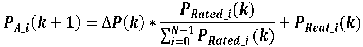 wherein PA(k+1) is the power output upper limit distributed to the i-th charging pile at time k+1, and PRated_i (k) is a rated power of the i-th charging pile; orwhen the performance state is the actual output power (PReal ) of the charging pile at the current time, the charging piles controller (12) is configured for:obtaining the power output upper limit distributed to each charging pile at time k+1 when an initial time k=0 according to the following formula:
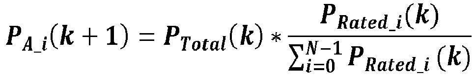 obtaining the power output upper limit distributed to each charging pile at time k+1 when k>0 according to the following formula:
 wherein PA_i(k+1) is the power output upper limit distributed to the i-th charging pile at time k+1, and PRated_i (k) is a rated power of the i-th charging pile; orwhen the performance state is a variation of the actual output power (ΔPReal ) of the charging pile at the current time, the charging piles controller (12) is configured for:obtaining a variation Δ P Real_i ( k ) of the actual output power of each charging pile at time k according to the following formula:
 obtaining the power output upper limit distributed to each charging pile at time k+1 when an initial time k=0 according to the following formula:
 obtaining the power output upper limit distributed to each charging pile at time k+1 when k>0 according to the following formula:
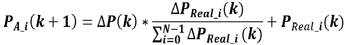 wherein PA(k+1) is the power output upper limit distributed to the i-th charging pile at time k+1, PRated_i (k) is a rated power of the i-th charging pile, and when
- The system (1) according to claim 11, wherein the charging station monitoring management system is further configured for updating the total power upper limit at every time.
Applications Claiming Priority (1)
| Application Number | Priority Date | Filing Date | Title |
|---|---|---|---|
| CN202111094782.6A CN115817254B (en) | 2021-09-17 | 2021-09-17 | Charging pile cluster power sharing control method, system and device |
Publications (1)
| Publication Number | Publication Date |
|---|---|
| EP4156431A1 true EP4156431A1 (en) | 2023-03-29 |
Family
ID=83004579
Family Applications (1)
| Application Number | Title | Priority Date | Filing Date |
|---|---|---|---|
| EP22191158.9A Pending EP4156431A1 (en) | 2021-09-17 | 2022-08-19 | Method, system and device for controlling power sharing of a cluster of charging piles |
Country Status (5)
| Country | Link |
|---|---|
| US (1) | US12609548B2 (en) |
| EP (1) | EP4156431A1 (en) |
| JP (1) | JP7428759B2 (en) |
| CN (1) | CN115817254B (en) |
| TW (1) | TWI820837B (en) |
Cited By (1)
| Publication number | Priority date | Publication date | Assignee | Title |
|---|---|---|---|---|
| EP4574547A1 (en) * | 2023-12-14 | 2025-06-25 | Delta Electronics, Inc. | Method of dynamically distributing output powers of charging piles |
Families Citing this family (15)
| Publication number | Priority date | Publication date | Assignee | Title |
|---|---|---|---|---|
| CN116476676B (en) * | 2023-06-21 | 2023-09-22 | 深圳市驰普科达科技有限公司 | Charging control circuit, charging control method and emergency charging vehicle |
| CN116512969B (en) * | 2023-07-04 | 2023-09-05 | 四川金信石信息技术有限公司 | Ordered charging power regulation and control method, system, terminal and medium for alternating-current charging pile |
| CN116853060B (en) * | 2023-08-08 | 2025-12-19 | 深圳市道通合创数字能源有限公司 | Charging power distribution method, device, charging management equipment, system and storage medium |
| CN117087497B (en) * | 2023-08-17 | 2024-03-08 | 广州巨湾技研有限公司 | Power control method for power battery system, and storage medium |
| CN117183799B (en) * | 2023-08-24 | 2024-12-31 | 深圳市建宏吉泰科技有限公司 | Charging pile state early warning method based on load balance |
| CN117141288B (en) * | 2023-09-11 | 2024-05-24 | 杭州闪充聚能新能源有限公司 | Load control method based on charging pile ad hoc network |
| US12422914B2 (en) * | 2023-09-29 | 2025-09-23 | Sk Hynix Nand Product Solutions Corp. | Dynamic power management among multiple memory devices |
| US12524337B2 (en) | 2023-09-29 | 2026-01-13 | Sk Hynix Nand Product Solutions Corp. | Host-controlled dynamic power management for memory devices |
| CN117022025B (en) * | 2023-10-10 | 2023-12-05 | 南京能可瑞科技有限公司 | Charging pile power balance distribution system and method thereof |
| CN117584790B (en) * | 2023-11-23 | 2024-06-18 | 北京海蓝云联技术有限公司 | Capacity-free charging pile control system |
| CN118238666B (en) * | 2024-05-28 | 2024-08-16 | 福建时代星云科技有限公司 | A power distribution method and terminal for a charging station |
| CN119091540A (en) * | 2024-09-25 | 2024-12-06 | 江西驴充充物联网科技有限公司 | A charging pile charging method and system based on balanced charging |
| CN120735645B (en) * | 2025-08-13 | 2026-01-27 | 车库七号新能源科技(深圳)有限公司 | New energy charging pile power distribution method and system for multiple charging guns |
| CN121084235B (en) * | 2025-11-11 | 2026-02-24 | 贵州理工学院 | A Smart Charging Service Optimization System and Method Based on Multi-Pile Cooperative Scheduling |
| CN121650508B (en) * | 2026-02-09 | 2026-04-10 | 温州蓝天能源科技股份有限公司 | Intelligent charging pile charging power distribution management method |
Citations (3)
| Publication number | Priority date | Publication date | Assignee | Title |
|---|---|---|---|---|
| CN108832682A (en) * | 2018-06-26 | 2018-11-16 | 蔚来汽车有限公司 | Power distribution system, capacity sharing system, intermediate node, terminal, method and equipment |
| CN108879831A (en) * | 2018-06-26 | 2018-11-23 | 蔚来汽车有限公司 | Power distribution system, capacity sharing system, master station, substation, method and equipment |
| CN106712166B (en) * | 2016-12-13 | 2019-10-29 | 深圳市盛弘电气股份有限公司 | A kind of charging station power method for automatically regulating and system |
Family Cites Families (14)
| Publication number | Priority date | Publication date | Assignee | Title |
|---|---|---|---|---|
| US20080297110A1 (en) | 2007-05-31 | 2008-12-04 | Kevin Cordes | Method and system for controlling the distribution of power in a multi-battery charger |
| US8810198B2 (en) * | 2011-09-02 | 2014-08-19 | Tesla Motors, Inc. | Multiport vehicle DC charging system with variable power distribution according to power distribution rules |
| JP6020247B2 (en) | 2013-02-20 | 2016-11-02 | 株式会社豊田自動織機 | Charging system |
| JP2015122868A (en) | 2013-12-24 | 2015-07-02 | 株式会社豊田自動織機 | Charging system, and charging station for electric vehicle |
| CN107848422A (en) * | 2015-05-08 | 2018-03-27 | Faa有限责任公司 | Battery charging station and related method of use |
| CN107994654A (en) * | 2017-12-29 | 2018-05-04 | 长园深瑞继保自动化有限公司 | Charging pile clustered control adaptive tracking control method |
| CN109572478B (en) | 2018-10-15 | 2020-07-28 | 上海交通大学 | Online stable charging system and method for electric vehicle of charging station |
| CN109532549B (en) | 2018-12-26 | 2021-03-30 | 深圳供电局有限公司 | Charging power adjustment method and device, computer equipment and storage medium |
| CN111845423A (en) | 2019-04-30 | 2020-10-30 | 天津平高智能电气有限公司 | A charging power distribution method and system for a charging stack |
| CN110303929B (en) | 2019-06-29 | 2023-04-18 | 华为数字能源技术有限公司 | Charging pile system management method and charging pile system |
| CN113315183B (en) | 2020-02-27 | 2025-06-06 | 台达电子企业管理(上海)有限公司 | Charging pile and its power distribution system and power distribution method |
| CN112319293B (en) | 2020-10-10 | 2022-09-27 | 浙江晨泰科技股份有限公司 | Control method for autonomous coordination power between charging piles |
| CN112653163B (en) * | 2020-12-21 | 2023-09-15 | 阳光新能源开发股份有限公司 | Energy storage system power distribution method and energy storage system |
| CN112874364A (en) | 2021-04-09 | 2021-06-01 | 安徽天能清洁能源科技有限公司 | Virtual power plant power control method and device based on charging pile |
-
2021
- 2021-09-17 CN CN202111094782.6A patent/CN115817254B/en active Active
-
2022
- 2022-07-05 US US17/810,827 patent/US12609548B2/en active Active
- 2022-08-01 TW TW111128806A patent/TWI820837B/en active
- 2022-08-10 JP JP2022127677A patent/JP7428759B2/en active Active
- 2022-08-19 EP EP22191158.9A patent/EP4156431A1/en active Pending
Patent Citations (3)
| Publication number | Priority date | Publication date | Assignee | Title |
|---|---|---|---|---|
| CN106712166B (en) * | 2016-12-13 | 2019-10-29 | 深圳市盛弘电气股份有限公司 | A kind of charging station power method for automatically regulating and system |
| CN108832682A (en) * | 2018-06-26 | 2018-11-16 | 蔚来汽车有限公司 | Power distribution system, capacity sharing system, intermediate node, terminal, method and equipment |
| CN108879831A (en) * | 2018-06-26 | 2018-11-23 | 蔚来汽车有限公司 | Power distribution system, capacity sharing system, master station, substation, method and equipment |
Cited By (1)
| Publication number | Priority date | Publication date | Assignee | Title |
|---|---|---|---|---|
| EP4574547A1 (en) * | 2023-12-14 | 2025-06-25 | Delta Electronics, Inc. | Method of dynamically distributing output powers of charging piles |
Also Published As
| Publication number | Publication date |
|---|---|
| JP2023044636A (en) | 2023-03-30 |
| CN115817254A (en) | 2023-03-21 |
| TWI820837B (en) | 2023-11-01 |
| TW202313374A (en) | 2023-04-01 |
| CN115817254B (en) | 2026-01-23 |
| JP7428759B2 (en) | 2024-02-06 |
| US20230086648A1 (en) | 2023-03-23 |
| US12609548B2 (en) | 2026-04-21 |
Similar Documents
| Publication | Publication Date | Title |
|---|---|---|
| EP4156431A1 (en) | Method, system and device for controlling power sharing of a cluster of charging piles | |
| EP3890153B1 (en) | Power supply method and power source | |
| US10457159B1 (en) | Power share converter for connecting multiple energy storage systems | |
| CN113098066B (en) | Power adjusting method, power adjusting device and terminal equipment | |
| CN111313527A (en) | Method for controlling power balance of direct current micro-grid system | |
| CN116353393B (en) | Charging pile power regulation and control method and system | |
| CN119253770B (en) | Control method of inverter hybrid parallel system and related equipment | |
| CN112865065A (en) | Power distribution network coordination control method and system containing high-permeability light storage | |
| EP4583356A1 (en) | Smart battery management system and method, and electronic device and readable storage medium | |
| CN115833306A (en) | Floating charge voltage management method and system for energy storage battery of power distribution network | |
| CN111313477B (en) | Charging power adjusting method and system | |
| CN114914925B (en) | Coordinated control method, device and medium of multi-terminal flexible DC transmission system based on average consistency | |
| CN117977772A (en) | Household load power supply method and device, and battery charging method and device | |
| EP4277075B1 (en) | PHOTOVOLTAIC SYSTEM AND POWER SUPPLY CONTROL METHOD FOR IT | |
| CN109768562A (en) | A power coordination control method for electric vehicle charging station | |
| CN116587909B (en) | A method and system for orderly charging management of new energy vehicles in private parking spaces in a residential area | |
| CN110474355A (en) | A method and system for optimizing the capacity configuration of a mobile energy storage charging device | |
| CN120546064B (en) | Micro-grid group coordination control method and system based on shared energy storage | |
| CN110733364A (en) | Power supply system and intelligent power supply method of double-gun direct-current power supply machines | |
| CN119315662B (en) | A method and system for charging and discharging energy storage converters | |
| CN116073451B (en) | A decentralized hybrid secondary frequency modulation control method for AC microgrids | |
| CN219372093U (en) | Multistage power management system of charging station | |
| CN107154620A (en) | Electrical system based on public bus and control method thereof | |
| CN119209721B (en) | Power supply system, control method of power supply system and electronic equipment | |
| CN214177193U (en) | Driving power take-off power generation system with double parallel alternating-current asynchronous generators |
Legal Events
| Date | Code | Title | Description |
|---|---|---|---|
| PUAI | Public reference made under article 153(3) epc to a published international application that has entered the european phase |
Free format text: ORIGINAL CODE: 0009012 |
|
| STAA | Information on the status of an ep patent application or granted ep patent |
Free format text: STATUS: THE APPLICATION HAS BEEN PUBLISHED |
|
| AK | Designated contracting states |
Kind code of ref document: A1 Designated state(s): AL AT BE BG CH CY CZ DE DK EE ES FI FR GB GR HR HU IE IS IT LI LT LU LV MC MK MT NL NO PL PT RO RS SE SI SK SM TR |
|
| STAA | Information on the status of an ep patent application or granted ep patent |
Free format text: STATUS: REQUEST FOR EXAMINATION WAS MADE |
|
| 17P | Request for examination filed |
Effective date: 20230912 |
|
| RBV | Designated contracting states (corrected) |
Designated state(s): AL AT BE BG CH CY CZ DE DK EE ES FI FR GB GR HR HU IE IS IT LI LT LU LV MC MK MT NL NO PL PT RO RS SE SI SK SM TR |
|
| RAP3 | Party data changed (applicant data changed or rights of an application transferred) |
Owner name: DELTA ELECTRONICS (SHANGHAI) CO., LTD. |