EP4156419A1 - Connector - Google Patents
Connector Download PDFInfo
- Publication number
- EP4156419A1 EP4156419A1 EP22197458.7A EP22197458A EP4156419A1 EP 4156419 A1 EP4156419 A1 EP 4156419A1 EP 22197458 A EP22197458 A EP 22197458A EP 4156419 A1 EP4156419 A1 EP 4156419A1
- Authority
- EP
- European Patent Office
- Prior art keywords
- connector
- conductive
- spring
- housing
- wire
- Prior art date
- Legal status (The legal status is an assumption and is not a legal conclusion. Google has not performed a legal analysis and makes no representation as to the accuracy of the status listed.)
- Pending
Links
Images


Classifications
-
- H—ELECTRICITY
- H01—ELECTRIC ELEMENTS
- H01R—ELECTRICALLY-CONDUCTIVE CONNECTIONS; STRUCTURAL ASSOCIATIONS OF A PLURALITY OF MUTUALLY-INSULATED ELECTRICAL CONNECTING ELEMENTS; COUPLING DEVICES; CURRENT COLLECTORS
- H01R13/00—Details of coupling devices of the kinds covered by groups H01R12/70 or H01R24/00 - H01R33/00
- H01R13/02—Contact members
- H01R13/22—Contacts for co-operating by abutting
- H01R13/24—Contacts for co-operating by abutting resilient; resiliently-mounted
- H01R13/2407—Contacts for co-operating by abutting resilient; resiliently-mounted characterized by the resilient means
- H01R13/2421—Contacts for co-operating by abutting resilient; resiliently-mounted characterized by the resilient means using coil springs
-
- H—ELECTRICITY
- H01—ELECTRIC ELEMENTS
- H01R—ELECTRICALLY-CONDUCTIVE CONNECTIONS; STRUCTURAL ASSOCIATIONS OF A PLURALITY OF MUTUALLY-INSULATED ELECTRICAL CONNECTING ELEMENTS; COUPLING DEVICES; CURRENT COLLECTORS
- H01R12/00—Structural associations of a plurality of mutually-insulated electrical connecting elements, specially adapted for printed circuits, e.g. printed circuit boards [PCB], flat or ribbon cables, or like generally planar structures, e.g. terminal strips, terminal blocks; Coupling devices specially adapted for printed circuits, flat or ribbon cables, or like generally planar structures; Terminals specially adapted for contact with, or insertion into, printed circuits, flat or ribbon cables, or like generally planar structures
- H01R12/70—Coupling devices
- H01R12/71—Coupling devices for rigid printing circuits or like structures
- H01R12/712—Coupling devices for rigid printing circuits or like structures co-operating with the surface of the printed circuit or with a coupling device exclusively provided on the surface of the printed circuit
- H01R12/714—Coupling devices for rigid printing circuits or like structures co-operating with the surface of the printed circuit or with a coupling device exclusively provided on the surface of the printed circuit with contacts abutting directly the printed circuit; Button contacts therefore provided on the printed circuit
-
- H—ELECTRICITY
- H01—ELECTRIC ELEMENTS
- H01R—ELECTRICALLY-CONDUCTIVE CONNECTIONS; STRUCTURAL ASSOCIATIONS OF A PLURALITY OF MUTUALLY-INSULATED ELECTRICAL CONNECTING ELEMENTS; COUPLING DEVICES; CURRENT COLLECTORS
- H01R13/00—Details of coupling devices of the kinds covered by groups H01R12/70 or H01R24/00 - H01R33/00
- H01R13/02—Contact members
- H01R13/15—Pins, blades or sockets having separate spring member for producing or increasing contact pressure
-
- H—ELECTRICITY
- H01—ELECTRIC ELEMENTS
- H01R—ELECTRICALLY-CONDUCTIVE CONNECTIONS; STRUCTURAL ASSOCIATIONS OF A PLURALITY OF MUTUALLY-INSULATED ELECTRICAL CONNECTING ELEMENTS; COUPLING DEVICES; CURRENT COLLECTORS
- H01R13/00—Details of coupling devices of the kinds covered by groups H01R12/70 or H01R24/00 - H01R33/00
- H01R13/46—Bases; Cases
- H01R13/502—Bases; Cases composed of different pieces
-
- H—ELECTRICITY
- H01—ELECTRIC ELEMENTS
- H01R—ELECTRICALLY-CONDUCTIVE CONNECTIONS; STRUCTURAL ASSOCIATIONS OF A PLURALITY OF MUTUALLY-INSULATED ELECTRICAL CONNECTING ELEMENTS; COUPLING DEVICES; CURRENT COLLECTORS
- H01R13/00—Details of coupling devices of the kinds covered by groups H01R12/70 or H01R24/00 - H01R33/00
- H01R13/62—Means for facilitating engagement or disengagement of coupling parts or for holding them in engagement
- H01R13/629—Additional means for facilitating engagement or disengagement of coupling parts, e.g. aligning or guiding means, levers, gas pressure electrical locking indicators, manufacturing tolerances
-
- H—ELECTRICITY
- H01—ELECTRIC ELEMENTS
- H01R—ELECTRICALLY-CONDUCTIVE CONNECTIONS; STRUCTURAL ASSOCIATIONS OF A PLURALITY OF MUTUALLY-INSULATED ELECTRICAL CONNECTING ELEMENTS; COUPLING DEVICES; CURRENT COLLECTORS
- H01R4/00—Electrically-conductive connections between two or more conductive members in direct contact, i.e. touching one another; Means for effecting or maintaining such contact; Electrically-conductive connections having two or more spaced connecting locations for conductors and using contact members penetrating insulation
- H01R4/28—Clamped connections, spring connections
- H01R4/48—Clamped connections, spring connections utilising a spring, clip, or other resilient member
-
- H—ELECTRICITY
- H01—ELECTRIC ELEMENTS
- H01R—ELECTRICALLY-CONDUCTIVE CONNECTIONS; STRUCTURAL ASSOCIATIONS OF A PLURALITY OF MUTUALLY-INSULATED ELECTRICAL CONNECTING ELEMENTS; COUPLING DEVICES; CURRENT COLLECTORS
- H01R13/00—Details of coupling devices of the kinds covered by groups H01R12/70 or H01R24/00 - H01R33/00
- H01R13/40—Securing contact members in or to a base or case; Insulating of contact members
-
- H—ELECTRICITY
- H01—ELECTRIC ELEMENTS
- H01R—ELECTRICALLY-CONDUCTIVE CONNECTIONS; STRUCTURAL ASSOCIATIONS OF A PLURALITY OF MUTUALLY-INSULATED ELECTRICAL CONNECTING ELEMENTS; COUPLING DEVICES; CURRENT COLLECTORS
- H01R4/00—Electrically-conductive connections between two or more conductive members in direct contact, i.e. touching one another; Means for effecting or maintaining such contact; Electrically-conductive connections having two or more spaced connecting locations for conductors and using contact members penetrating insulation
- H01R4/10—Electrically-conductive connections between two or more conductive members in direct contact, i.e. touching one another; Means for effecting or maintaining such contact; Electrically-conductive connections having two or more spaced connecting locations for conductors and using contact members penetrating insulation effected solely by twisting, wrapping, bending, crimping, or other permanent deformation
- H01R4/18—Electrically-conductive connections between two or more conductive members in direct contact, i.e. touching one another; Means for effecting or maintaining such contact; Electrically-conductive connections having two or more spaced connecting locations for conductors and using contact members penetrating insulation effected solely by twisting, wrapping, bending, crimping, or other permanent deformation by crimping
- H01R4/20—Electrically-conductive connections between two or more conductive members in direct contact, i.e. touching one another; Means for effecting or maintaining such contact; Electrically-conductive connections having two or more spaced connecting locations for conductors and using contact members penetrating insulation effected solely by twisting, wrapping, bending, crimping, or other permanent deformation by crimping using a crimping sleeve
Definitions
- the disclosure relates to electrical connection technology and, more particularly, to a connector.
- the current connector usually includes a male terminal 101 and a female terminal 102 that mutually inserted into each other (for example, as shown in FIG. 1 ).
- the male terminal and the female terminal need an angular coordination (for example, when the mating surface at one terminal is plane), while the mutually inserted structure cannot adapt to this application.
- the mutually inserted structure not only has complex assembly, high cost, but also occupies a large space. Therefore, a connector with simple structure and easy to use is urgently needed.
- an aspect of the present invention provides a connector for electrical connection between a wire and a conductive load
- the connector comprises: a housing; and at least one elastic conductive component, a portion of each of the at least one elastic conductive component passes through the housing, and the each of the elastic conductive component is connectable to the wire, and wherein the each of the elastic conductive component is configured to be movable up and down relative to the housing, so that the each of the elastic conductive component is in contact with the conductive load or separate from the conductive load, to establish or release the electrical connection between the wire and the conductive load.
- the connector as outlined above may further comprise one or more of the following preferred forms.
- the each of the elastic conductive component includes a conductive terminal and a spring, and the wire is connected to the conductive terminal, wherein the conductive terminal moves up and down relative to the housing by cooperating with the spring, so that the conductive terminal is in contact with or separate from the conductive load.
- the conductive terminal includes an upper part and a lower part that is connected with the wire, the lower part includes a first accommodating cavity to accommodate the upper part and the spring, wherein the spring can be compressed to move downward via the upper part, and the upper part can be pushed to move upward via the spring.
- the lower part includes a locking part
- the housing is provided with a matching locking part
- the lower part is fixed in the housing through cooperation of the locking part and the matching locking part.
- the upper part is fixedly connected with one end of the spring, and the other end of the spring is fixedly connected with the bottom of the first accommodating cavity.
- a first stop part is disposed on the lower part to prevent the upper part from leaving the lower part.
- a second accommodating cavity is disposed in the lower part to accommodate the wire.
- the spring wraps around an outer surface of the conductive terminal, the spring can be compressed via the conductive terminal to move downward, and the conductive terminal can be pushed via the spring to move upward.
- the housing is provided with a second stop part to constrain the conductive terminal in the housing.
- the connector of the present invention has simple structure, small size, and is applicable to the scenarios where the mating surface at one terminal is plane.
- the present invention provides a connector for electrical connection between a wire and a conductive load
- the connector comprises: a housing; at least one elastic conductive component, a portion of each of the at least one elastic conductive component passes through the housing, and the each of the elastic conductive component is connectable to the wire, and wherein the each of the elastic conductive component is configured to be movable up and down relative to the housing, so that the each of the elastic conductive component is in contact with the conductive load or separate from the conductive load, to establish or release the electrical connection between the wire and the conductive load.
- Some concepts in the present invention are relative concepts with reference to FIG. 2 , FIG. 3 and FIG. 4 , such as front, rear, left, right, upper, lower, front end, rear end, left end, right end, upper part, lower part, left side, right side, longitudinal, transverse, etc.
- the electrical equipment (not shown in the figures) includes an electrical equipment housing, a power supply rack, a power supply board (the power supply board includes a conductive load 406 as shown in FIG. 8 and FIG. 9 ) and a connector 200 (as shown in FIG. 2 ).
- the connector 200 is disposed on the power supply rack, wherein the connector 200 is installed on the electrical equipment via the mounting holes 208a and 208b as shown in FIG. 2 .
- the connector 200 includes a housing 202 and two elastic conductive components 204, 206.
- the elastic conductive component 204 includes a conductive terminal 204a and a spring 204d
- the conductive terminal 204a includes an upper part 204b and a lower part 204c
- the lower part 204c is connected with the wire 300a.
- the lower part 204c includes an accommodating cavity 210 (i.e., the first accommodating cavity) and an accommodating cavity 212 (i.e., the second accommodating cavity), the upper part 204b and the spring 204d are accommodated in the accommodating cavity 210.
- One end of the spring 204d is fixedly connected with the upper part 204b, the other end of the spring 204d is fixedly connected with the bottom of the accommodating cavity 210.
- the wire 300a is accommodated in the accommodating cavity 212.
- the spring 204d can be compressed to move downward via the upper part 204a in the accommodating cavity 210, and the upper part 204a can be pushed to move upward through the spring 204d in the accommodating cavity 210.
- the lower part 204c includes a stop part 2040a (i.e., the first stop part) to prevent the upper part 204b from leaving the lower part 204c.
- the lower part 204c includes locking parts (2044a, 2044b) (such as a pair of protrusions), and the housing 202 is provided with matching locking parts (2000a, 2000b) (such as a pair of grooves matched with the pair of protrusions), the lower part 204c is fixed in the housing 202 with cooperation of the locking parts (2044a, 2044b) and the matching locking parts (2000a, 2000b).
- the elastic conductive component 206 includes a conductive terminal 206a and a spring 206d
- the conductive terminal 206a includes an upper part 206b and a lower part 206c
- the lower part 206c is connected with the wire 300b.
- the lower part 206c includes accommodating cavities 214 and 216
- the upper part 206b and the spring 206d are accommodated in the accommodating cavity 214.
- One end of the spring 206d is fixedly connected with the upper part 206b, and the other end of the spring 206d is fixedly connected with the bottom of the accommodating cavity 214.
- the wire 300b is accommodated in the accommodating cavity 216.
- the spring 206d can be compressed to move downward via the upper part 206a in the accommodating cavity 214, and the upper part 206a can be pushed to move upward via the spring 206d in the accommodating cavity 214.
- the structure of the elastic conductive component 206 is exactly the same as the structure of the elastic component 204, so the other details of the elastic conductive component 206 will not be described herein.
- the upper part 204b of the conductive terminal 204a of the elastic conductive component 204 and the upper part 206b of the conductive terminal 206a of the elastic conductive component 206 are in contact with the protrusions 406a and 406b of the conductive load 406, respectively (as shown in FIG. 8 ), so as to establish the electrical connection between the wire 300a and the conductive load 406, and the electrical connection between the wire 300b and the conductive load 406.
- the upper part 204b of the conductive terminal 204a and the upper part 206b of the conductive terminal 206a of the elastic conductive component 206 are separated from the conductive load 406, so that the electrical connection between the wire 300a and the conductive load 406, and the electrical connection between the conductor 300b and the conductive load 406 are disconnected.
- the upper part 204b of the conductive terminal 204a and the upper part 206b of the conductive terminal 206a of the elastic conductive component 206 return to the initial position state under the action of the spring force respectively.
- the conductive load is integrated with the power supply board, in another embodiment, the conductive load can also be an independent component.
- an electrical connection is formed by contacting the upper part 204b of the conductive terminal 204a and the upper part 206b of the conductive terminal 206a with the protrusion 406a and the protrusion 406b respectively (as shown in FIG. 8 and FIG. 9 ), in another embodiment, the protrusion 406a and the protrusion 406b can be replaced by a pair of recesses, the upper part 204b of the conductive terminal 204a and the upper part 206b of the conductive terminal 206a could form an electrical connection by contacting with one of the pair of recesses respectively.
- the connector 700 includes a housing 702 and two elastic conductive components 704, 706.
- the basic structure of the connector 700 is the same as that of the connector 200. The difference is between the structure of the elastic conductive component 704 and the elastic conductive component 204.
- the elastic conductive component 704 includes an integrated conductive terminal 704a and a spring 704c that wraps around an outer surface of the conductive terminal 704a.
- the wire 300a is accommodated in the accommodating cavity 714 of the conductive terminal 704a, and the buckle 702a (i.e., the second stop part) constrains the conductive terminal 704a in the housing 702.
- the buckle 702a can only cover a part of the spring 704c, and another part of the spring 704c is exposed outside the housing 702.
- the elastic conductive component 706 includes an integral conductive terminal 706a and a spring 706c that wraps around an outer surface of the conductive terminal 706a, the wire 300b is accommodated in the accommodating cavity 716 of the conductive terminal 706a.
- the buckle 702b constrains the conductive terminal 706a in the housing 702. What's more, the buckle 702b can only cover part of the spring 706c, and another part of the spring 706 is exposed outside the housing 702.
- the buckles 702a and 702b are integrated with the housing 702. In the embodiment shown in FIG.
- the number of the buckles 702a and 702b is three, and in another embodiment, the number of the buckles 702a and 702b can be more than three. It is to be understood that although in the above embodiments, the wire is electrically connected with the conductive terminal by being accommodated in the accommodating cavity, in other embodiments, the wire can be electrically connected with the conductive terminal in other suitable ways.
- the connector of the present invention Compared with a connector in the prior art, the connector of the present invention has simple structure, small size, and is applicable to the scenarios where the mating surface at one terminal is plane.
Landscapes
- Details Of Connecting Devices For Male And Female Coupling (AREA)
- Connections Arranged To Contact A Plurality Of Conductors (AREA)
Abstract
Description
- The disclosure relates to electrical connection technology and, more particularly, to a connector.
- The current connector usually includes a
male terminal 101 and afemale terminal 102 that mutually inserted into each other (for example, as shown inFIG. 1 ). However, if the space is limited, the male terminal and the female terminal need an angular coordination (for example, when the mating surface at one terminal is plane), while the mutually inserted structure cannot adapt to this application. Besides, the mutually inserted structure not only has complex assembly, high cost, but also occupies a large space. Therefore, a connector with simple structure and easy to use is urgently needed. - In view of the problem of prior art, an aspect of the present invention provides a connector for electrical connection between a wire and a conductive load, the connector comprises: a housing; and at least one elastic conductive component, a portion of each of the at least one elastic conductive component passes through the housing, and the each of the elastic conductive component is connectable to the wire, and wherein the each of the elastic conductive component is configured to be movable up and down relative to the housing, so that the each of the elastic conductive component is in contact with the conductive load or separate from the conductive load, to establish or release the electrical connection between the wire and the conductive load.
- According to the aforementioned aspect, the connector as outlined above may further comprise one or more of the following preferred forms.
- In some preferred forms, the each of the elastic conductive component includes a conductive terminal and a spring, and the wire is connected to the conductive terminal, wherein the conductive terminal moves up and down relative to the housing by cooperating with the spring, so that the conductive terminal is in contact with or separate from the conductive load.
- In some preferred forms, the conductive terminal includes an upper part and a lower part that is connected with the wire, the lower part includes a first accommodating cavity to accommodate the upper part and the spring, wherein the spring can be compressed to move downward via the upper part, and the upper part can be pushed to move upward via the spring.
- In some preferred forms, the lower part includes a locking part, the housing is provided with a matching locking part, and the lower part is fixed in the housing through cooperation of the locking part and the matching locking part.
- In some preferred forms, the upper part is fixedly connected with one end of the spring, and the other end of the spring is fixedly connected with the bottom of the first accommodating cavity.
- In some preferred forms, a first stop part is disposed on the lower part to prevent the upper part from leaving the lower part.
- In some preferred forms, a second accommodating cavity is disposed in the lower part to accommodate the wire.
- In some preferred forms, the spring wraps around an outer surface of the conductive terminal, the spring can be compressed via the conductive terminal to move downward, and the conductive terminal can be pushed via the spring to move upward.
- In some preferred forms, the housing is provided with a second stop part to constrain the conductive terminal in the housing.
- Compared with the prior art, the connector of the present invention has simple structure, small size, and is applicable to the scenarios where the mating surface at one terminal is plane.
- Various embodiments will be illustrated and explained hereinafter with reference to the accompanying figures. The figures serve to illustrate the basic principle, so that only aspects necessary for understanding the basic principle are illustrated. It should be noted that the figures are not drawn to scale and the use of the same reference numbers in different figures indicates similar or identical features.
-
FIG. 1 is a schematic view of an example connector according to the prior art. -
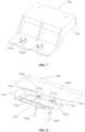
FIG. 2 is a schematic perspective view of an example connector according to an embodiment of the disclosure. -
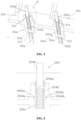
FIG. 3 is a partial sectional view of the connector ofFIG. 2 . -
FIG. 4 is an enlarged schematic view of area A of the connector ofFIG. 3 . -
FIG. 5 is a schematic perspective view of an example connector according to another embodiment of the disclosure. -
FIG. 6 is a partial cross-sectional view ofFIG. 5 . -
FIG. 7 is a perspective view of the connector inFIG. 5 after removing the conductive terminal. -
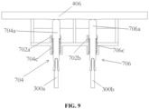
FIG. 8 is a perspective view of the connector inFig. 5 in electrical contact with a conductive load. -
FIG. 9 is a front view of the connector ofFIG. 8 . - Hereinafter, details of the preferred embodiments will be described with reference to the figures that form part of the invention. The figures illustrate particular embodiments of the invention by way of example only and the illustrated embodiments are not intended to present an exhaustive list of embodiments of the invention. It is to be understood that other embodiments may be utilized and that structural or logical modifications may be made without departing from the spirit and scope of the invention. Therefore, the following description is not intended to limit the scope of the invention, which is defined by the appended claims.
- The present invention provides a connector for electrical connection between a wire and a conductive load, the connector comprises: a housing; at least one elastic conductive component, a portion of each of the at least one elastic conductive component passes through the housing, and the each of the elastic conductive component is connectable to the wire, and wherein the each of the elastic conductive component is configured to be movable up and down relative to the housing, so that the each of the elastic conductive component is in contact with the conductive load or separate from the conductive load, to establish or release the electrical connection between the wire and the conductive load.
- The following is an example of the application of the connector in electrical equipment, the embodiments of the present invention will be described in detail in combination with the accompanying figures.
- Some concepts in the present invention are relative concepts with reference to
FIG. 2 ,FIG. 3 and FIG. 4 , such as front, rear, left, right, upper, lower, front end, rear end, left end, right end, upper part, lower part, left side, right side, longitudinal, transverse, etc. - In one embodiment, the electrical equipment (not shown in the figures) includes an electrical equipment housing, a power supply rack, a power supply board (the power supply board includes a
conductive load 406 as shown inFIG. 8 andFIG. 9 ) and a connector 200 (as shown inFIG. 2 ). Theconnector 200 is disposed on the power supply rack, wherein theconnector 200 is installed on the electrical equipment via themounting holes FIG. 2 . - As shown in
FIGS. 2-4 , theconnector 200 includes ahousing 202 and two elasticconductive components - As shown in
FIG. 3 and FIG. 4 , the elasticconductive component 204 includes aconductive terminal 204a and aspring 204d, theconductive terminal 204a includes anupper part 204b and alower part 204c, thelower part 204c is connected with thewire 300a. Thelower part 204c includes an accommodating cavity 210 (i.e., the first accommodating cavity) and an accommodating cavity 212 (i.e., the second accommodating cavity), theupper part 204b and thespring 204d are accommodated in theaccommodating cavity 210. One end of thespring 204d is fixedly connected with theupper part 204b, the other end of thespring 204d is fixedly connected with the bottom of theaccommodating cavity 210. Thewire 300a is accommodated in theaccommodating cavity 212. Thespring 204d can be compressed to move downward via theupper part 204a in theaccommodating cavity 210, and theupper part 204a can be pushed to move upward through thespring 204d in theaccommodating cavity 210. Moreover, thelower part 204c includes astop part 2040a (i.e., the first stop part) to prevent theupper part 204b from leaving thelower part 204c. Thelower part 204c includes locking parts (2044a, 2044b) (such as a pair of protrusions), and thehousing 202 is provided with matching locking parts (2000a, 2000b) (such as a pair of grooves matched with the pair of protrusions), thelower part 204c is fixed in thehousing 202 with cooperation of the locking parts (2044a, 2044b) and the matching locking parts (2000a, 2000b). - As shown in
FIG. 3 and FIG. 4 , the elasticconductive component 206 includes aconductive terminal 206a and aspring 206d, theconductive terminal 206a includes anupper part 206b and alower part 206c, thelower part 206c is connected with thewire 300b. Besides, thelower part 206c includesaccommodating cavities upper part 206b and thespring 206d are accommodated in theaccommodating cavity 214. One end of thespring 206d is fixedly connected with theupper part 206b, and the other end of thespring 206d is fixedly connected with the bottom of the accommodating cavity 214.Thewire 300b is accommodated in theaccommodating cavity 216. In addition, thespring 206d can be compressed to move downward via theupper part 206a in theaccommodating cavity 214, and theupper part 206a can be pushed to move upward via thespring 206d in theaccommodating cavity 214. The structure of the elasticconductive component 206 is exactly the same as the structure of theelastic component 204, so the other details of the elasticconductive component 206 will not be described herein. - Combining
FIG. 2 ,FIG. 8 andFig. 9 , when theconnector 200 is disposed on the power supply rack of the electrical equipment, theupper part 204b of theconductive terminal 204a extends upward through the power supply rack. When the power supply board is placed in the electrical equipment, the conductive load 406 (which is the same as theconductive load 406 inFIG. 8 andFIG. 9 ) on the power supply board presses the elasticconductive component 204 and the elasticconductive component 206. Specifically, theupper part 204b of theconductive terminal 204a of the elasticconductive component 204 and theupper part 206b of theconductive terminal 206a of the elasticconductive component 206 are in contact with theprotrusions conductive load 406, respectively (as shown inFIG. 8 ), so as to establish the electrical connection between thewire 300a and theconductive load 406, and the electrical connection between thewire 300b and theconductive load 406. When the power supply board is removed from the electrical equipment, theupper part 204b of theconductive terminal 204a and theupper part 206b of theconductive terminal 206a of the elasticconductive component 206 are separated from theconductive load 406, so that the electrical connection between thewire 300a and theconductive load 406, and the electrical connection between theconductor 300b and theconductive load 406 are disconnected. Theupper part 204b of theconductive terminal 204a and theupper part 206b of theconductive terminal 206a of the elasticconductive component 206 return to the initial position state under the action of the spring force respectively. It is to be understood that in the embodiment shown inFIGS. 2-4 , the conductive load is integrated with the power supply board, in another embodiment, the conductive load can also be an independent component. It is also to be understood that in the embodiment shown inFIGS. 2-4 , an electrical connection is formed by contacting theupper part 204b of theconductive terminal 204a and theupper part 206b of theconductive terminal 206a with theprotrusion 406a and theprotrusion 406b respectively (as shown inFIG. 8 andFIG. 9 ), in another embodiment, theprotrusion 406a and theprotrusion 406b can be replaced by a pair of recesses, theupper part 204b of theconductive terminal 204a and theupper part 206b of theconductive terminal 206a could form an electrical connection by contacting with one of the pair of recesses respectively. - In another embodiment, as shown in
FIGS. 5-9 , theconnector 700 includes ahousing 702 and two elasticconductive components connector 700 is the same as that of theconnector 200. The difference is between the structure of the elasticconductive component 704 and the elasticconductive component 204. The elasticconductive component 704 includes an integratedconductive terminal 704a and aspring 704c that wraps around an outer surface of theconductive terminal 704a. Thewire 300a is accommodated in theaccommodating cavity 714 of theconductive terminal 704a, and thebuckle 702a (i.e., the second stop part) constrains theconductive terminal 704a in thehousing 702. Moreover, thebuckle 702a can only cover a part of thespring 704c, and another part of thespring 704c is exposed outside thehousing 702. The elasticconductive component 706 includes an integral conductive terminal 706a and aspring 706c that wraps around an outer surface of theconductive terminal 706a, thewire 300b is accommodated in theaccommodating cavity 716 of theconductive terminal 706a. Thebuckle 702b constrains theconductive terminal 706a in thehousing 702. What's more, thebuckle 702b can only cover part of thespring 706c, and another part of thespring 706 is exposed outside thehousing 702. Thebuckles housing 702. In the embodiment shown inFIG. 7 , the number of thebuckles buckles - Compared with a connector in the prior art, the connector of the present invention has simple structure, small size, and is applicable to the scenarios where the mating surface at one terminal is plane.
- It is to be understood that although the application in electrical equipment is specifically described in the above embodiments for illustration, the above technical scheme can also be applied to other application scenarios where the mating surface at one terminal is plane.
- While the invention has been described with reference to particular embodiments thereof, the particular embodiments are provided merely as examples and are not intended to limit the scope of the invention. It will be apparent to those skilled in the art that various alterations and modifications, additions or deletions may be made to the disclosed embodiments without departing from the spirit and scope of the invention.
Claims (9)
- A connector for electrical connection between a wire and a conductive load, the connector comprising:a housing;at least one elastic conductive component, a portion of each of the at least one elastic conductive component passing through the housing, and the each of the elastic conductive component being connectable to the wire; andwherein the each of the elastic conductive component is configured to be movable up and down relative to the housing, so that the each of the elastic conductive component is in contact with the conductive load or separate from the conductive load, to establish or release the electrical connection between the wire and the conductive load.
- The connector of claim 1, wherein the each of the elastic conductive component includes a conductive terminal and a spring, and the wire is connected to the conductive terminal, wherein the conductive terminal moves up and down relative to the housing by cooperating with the spring, so that the conductive terminal is in contact with or separate from the conductive load.
- The connector of claim 2, wherein the conductive terminal includes an upper part and a lower part that is connected with the wire, the lower part including a first accommodating cavity to accommodate the upper part and the spring, wherein the spring can be compressed to move downward via the upper part, and the upper part can be pushed to move upward via the spring.
- The connector of claim 3, wherein the lower part includes a locking part, the housing is provided with a matching locking part, and the lower part is fixed in the housing through cooperation of the locking part and the matching locking part.
- The connector of claim 3, wherein the upper part is fixedly connected with one end of the spring, and the other end of the spring is fixedly connected with the bottom of the first accommodating cavity.
- The connector of claim 5, wherein a first stop part is disposed on the lower part to prevent the upper part from leaving the lower part.
- The connector of claim 3, wherein a second accommodating cavity is disposed in the lower part to accommodate the wire.
- The connector of claims 2, wherein the spring wraps around an outer surface of the conductive terminal, the spring can be compressed via the conductive terminal to move downward, and the conductive terminal can be pushed via the spring to move upward.
- The connector of claim 8, wherein the housing is provided with a second stop part to constrain the conductive terminal in the housing.
Applications Claiming Priority (1)
| Application Number | Priority Date | Filing Date | Title |
|---|---|---|---|
| CN202111133697.6A CN115882258A (en) | 2021-09-27 | 2021-09-27 | Connector with a locking member |
Publications (1)
| Publication Number | Publication Date |
|---|---|
| EP4156419A1 true EP4156419A1 (en) | 2023-03-29 |
Family
ID=83438534
Family Applications (1)
| Application Number | Title | Priority Date | Filing Date |
|---|---|---|---|
| EP22197458.7A Pending EP4156419A1 (en) | 2021-09-27 | 2022-09-23 | Connector |
Country Status (3)
| Country | Link |
|---|---|
| US (1) | US12476405B2 (en) |
| EP (1) | EP4156419A1 (en) |
| CN (1) | CN115882258A (en) |
Families Citing this family (2)
| Publication number | Priority date | Publication date | Assignee | Title |
|---|---|---|---|---|
| CN115882258A (en) * | 2021-09-27 | 2023-03-31 | 泰科电子(上海)有限公司 | Connector with a locking member |
| CN116742379B (en) * | 2023-08-03 | 2026-04-21 | 深圳泰华互联技术有限公司 | A manually switchable power connector plug |
Citations (8)
| Publication number | Priority date | Publication date | Assignee | Title |
|---|---|---|---|---|
| US20040077225A1 (en) * | 2002-10-21 | 2004-04-22 | L & K Precision Industry Co., Ltd. | Electrical connector with movable pin |
| US20070134995A1 (en) * | 2003-11-20 | 2007-06-14 | Xiang Xu | Electrical terminal |
| US7713095B2 (en) * | 2008-04-23 | 2010-05-11 | Yokowo Co., Ltd. | Contact |
| WO2015141945A1 (en) * | 2014-03-21 | 2015-09-24 | 타이코에이엠피 주식회사 | Cable assembly, camera module, and camera device for vehicle including same |
| EP2963741B1 (en) * | 2014-07-02 | 2017-08-09 | Robert Virant | Rear seat infotainment system and multiple electrical connector for such a system |
| US20180084873A1 (en) * | 2016-09-23 | 2018-03-29 | Apple Inc. | Accessory contacts |
| EP3843224A1 (en) * | 2018-11-23 | 2021-06-30 | Gigalane Co. Ltd | Housing-integrated board-mating connector and manufacturing method therefor |
| US20210257766A1 (en) * | 2020-02-19 | 2021-08-19 | Molex, Llc | Electrical connector and electrical connector assembly |
Family Cites Families (8)
| Publication number | Priority date | Publication date | Assignee | Title |
|---|---|---|---|---|
| CH674106A5 (en) * | 1986-05-21 | 1990-04-30 | Feinmetall Gmbh | Spring contact pin for electronic timepiece circuit board test adaptor |
| CN101350464B (en) * | 2007-07-20 | 2011-05-04 | 深圳富泰宏精密工业有限公司 | Conductive pole and electronic device containing the same |
| US7731513B1 (en) * | 2009-04-08 | 2010-06-08 | Lotes Co., Ltd | Conductive assembly and electrical connector having the same |
| US8337256B1 (en) * | 2011-08-26 | 2012-12-25 | Cheng Uei Precision Industry Co., Ltd. | Pogo-pin connector |
| CN210926398U (en) * | 2019-08-06 | 2020-07-03 | 泰科电子(上海)有限公司 | Electric connector, connector assembly and electronic equipment |
| CN112421278A (en) * | 2019-08-23 | 2021-02-26 | 泰科电子(上海)有限公司 | Electrical Connectors and Electrical Connector Assemblies |
| CN113540856B (en) * | 2020-04-20 | 2023-08-25 | 泰科电子(上海)有限公司 | Connector |
| CN115882258A (en) * | 2021-09-27 | 2023-03-31 | 泰科电子(上海)有限公司 | Connector with a locking member |
-
2021
- 2021-09-27 CN CN202111133697.6A patent/CN115882258A/en active Pending
-
2022
- 2022-09-23 EP EP22197458.7A patent/EP4156419A1/en active Pending
- 2022-09-27 US US17/953,758 patent/US12476405B2/en active Active
Patent Citations (8)
| Publication number | Priority date | Publication date | Assignee | Title |
|---|---|---|---|---|
| US20040077225A1 (en) * | 2002-10-21 | 2004-04-22 | L & K Precision Industry Co., Ltd. | Electrical connector with movable pin |
| US20070134995A1 (en) * | 2003-11-20 | 2007-06-14 | Xiang Xu | Electrical terminal |
| US7713095B2 (en) * | 2008-04-23 | 2010-05-11 | Yokowo Co., Ltd. | Contact |
| WO2015141945A1 (en) * | 2014-03-21 | 2015-09-24 | 타이코에이엠피 주식회사 | Cable assembly, camera module, and camera device for vehicle including same |
| EP2963741B1 (en) * | 2014-07-02 | 2017-08-09 | Robert Virant | Rear seat infotainment system and multiple electrical connector for such a system |
| US20180084873A1 (en) * | 2016-09-23 | 2018-03-29 | Apple Inc. | Accessory contacts |
| EP3843224A1 (en) * | 2018-11-23 | 2021-06-30 | Gigalane Co. Ltd | Housing-integrated board-mating connector and manufacturing method therefor |
| US20210257766A1 (en) * | 2020-02-19 | 2021-08-19 | Molex, Llc | Electrical connector and electrical connector assembly |
Also Published As
| Publication number | Publication date |
|---|---|
| US20230101670A1 (en) | 2023-03-30 |
| CN115882258A (en) | 2023-03-31 |
| US12476405B2 (en) | 2025-11-18 |
Similar Documents
| Publication | Publication Date | Title |
|---|---|---|
| JP5563241B2 (en) | Electrical connector | |
| JP7366717B2 (en) | connector assembly | |
| KR101471283B1 (en) | Electrical connector for use with a circuit board | |
| CN111164840A (en) | Connector | |
| US5848912A (en) | Half-fitting prevention connector | |
| US8092232B2 (en) | Board-to-board connector | |
| CN109616829B (en) | Connector with a locking member | |
| US9502815B2 (en) | Electrical connector | |
| CN111244654A (en) | Connector with a locking member | |
| US20150229050A1 (en) | Wire-to-board connector | |
| CN101971431B (en) | Coaxial connector | |
| CN101361230A (en) | Connector | |
| US20070212950A1 (en) | Electrical connector terminal housing | |
| CN113826283B (en) | Connectors and connectors | |
| US10177477B2 (en) | Connector and connector assembly | |
| KR20170003725A (en) | Electrical connector with terminal holder | |
| US12476405B2 (en) | Connector for electrical connection between a wire and a conductive load | |
| US20170179626A1 (en) | Connector | |
| EP2538501B1 (en) | Connector | |
| US7811105B1 (en) | Electrical connector housing with an actuator to release the electrical connector housing from an electrical connector | |
| US10230185B2 (en) | Connector device | |
| CN112350124B (en) | Connector with a locking member | |
| JP6839472B1 (en) | Electrical connection structure | |
| US20240022021A1 (en) | Plug, connector, and receptacle | |
| US10128605B2 (en) | Connector |
Legal Events
| Date | Code | Title | Description |
|---|---|---|---|
| PUAI | Public reference made under article 153(3) epc to a published international application that has entered the european phase |
Free format text: ORIGINAL CODE: 0009012 |
|
| STAA | Information on the status of an ep patent application or granted ep patent |
Free format text: STATUS: THE APPLICATION HAS BEEN PUBLISHED |
|
| AK | Designated contracting states |
Kind code of ref document: A1 Designated state(s): AL AT BE BG CH CY CZ DE DK EE ES FI FR GB GR HR HU IE IS IT LI LT LU LV MC MK MT NL NO PL PT RO RS SE SI SK SM TR |
|
| STAA | Information on the status of an ep patent application or granted ep patent |
Free format text: STATUS: REQUEST FOR EXAMINATION WAS MADE |
|
| 17P | Request for examination filed |
Effective date: 20230920 |
|
| RBV | Designated contracting states (corrected) |
Designated state(s): AL AT BE BG CH CY CZ DE DK EE ES FI FR GB GR HR HU IE IS IT LI LT LU LV MC MK MT NL NO PL PT RO RS SE SI SK SM TR |
|
| STAA | Information on the status of an ep patent application or granted ep patent |
Free format text: STATUS: EXAMINATION IS IN PROGRESS |
|
| 17Q | First examination report despatched |
Effective date: 20241223 |