EP4156401A1 - Diaphragm, and battery comprising same - Google Patents
Diaphragm, and battery comprising same Download PDFInfo
- Publication number
- EP4156401A1 EP4156401A1 EP21868499.1A EP21868499A EP4156401A1 EP 4156401 A1 EP4156401 A1 EP 4156401A1 EP 21868499 A EP21868499 A EP 21868499A EP 4156401 A1 EP4156401 A1 EP 4156401A1
- Authority
- EP
- European Patent Office
- Prior art keywords
- separator
- ceramic coating
- separator according
- ceramic
- ranges
- Prior art date
- Legal status (The legal status is an assumption and is not a legal conclusion. Google has not performed a legal analysis and makes no representation as to the accuracy of the status listed.)
- Pending
Links
Images


Classifications
-
- H—ELECTRICITY
- H01—ELECTRIC ELEMENTS
- H01M—PROCESSES OR MEANS, e.g. BATTERIES, FOR THE DIRECT CONVERSION OF CHEMICAL ENERGY INTO ELECTRICAL ENERGY
- H01M50/00—Constructional details or processes of manufacture of the non-active parts of electrochemical cells other than fuel cells, e.g. hybrid cells
- H01M50/40—Separators; Membranes; Diaphragms; Spacing elements inside cells
- H01M50/409—Separators, membranes or diaphragms characterised by the material
- H01M50/449—Separators, membranes or diaphragms characterised by the material having a layered structure
- H01M50/451—Separators, membranes or diaphragms characterised by the material having a layered structure comprising layers of only organic material and layers containing inorganic material
-
- H—ELECTRICITY
- H01—ELECTRIC ELEMENTS
- H01M—PROCESSES OR MEANS, e.g. BATTERIES, FOR THE DIRECT CONVERSION OF CHEMICAL ENERGY INTO ELECTRICAL ENERGY
- H01M10/00—Secondary cells; Manufacture thereof
- H01M10/05—Accumulators with non-aqueous electrolyte
- H01M10/052—Li-accumulators
-
- H—ELECTRICITY
- H01—ELECTRIC ELEMENTS
- H01M—PROCESSES OR MEANS, e.g. BATTERIES, FOR THE DIRECT CONVERSION OF CHEMICAL ENERGY INTO ELECTRICAL ENERGY
- H01M10/00—Secondary cells; Manufacture thereof
- H01M10/05—Accumulators with non-aqueous electrolyte
- H01M10/052—Li-accumulators
- H01M10/0525—Rocking-chair batteries, i.e. batteries with lithium insertion or intercalation in both electrodes; Lithium-ion batteries
-
- H—ELECTRICITY
- H01—ELECTRIC ELEMENTS
- H01M—PROCESSES OR MEANS, e.g. BATTERIES, FOR THE DIRECT CONVERSION OF CHEMICAL ENERGY INTO ELECTRICAL ENERGY
- H01M50/00—Constructional details or processes of manufacture of the non-active parts of electrochemical cells other than fuel cells, e.g. hybrid cells
- H01M50/40—Separators; Membranes; Diaphragms; Spacing elements inside cells
- H01M50/403—Manufacturing processes of separators, membranes or diaphragms
-
- H—ELECTRICITY
- H01—ELECTRIC ELEMENTS
- H01M—PROCESSES OR MEANS, e.g. BATTERIES, FOR THE DIRECT CONVERSION OF CHEMICAL ENERGY INTO ELECTRICAL ENERGY
- H01M50/00—Constructional details or processes of manufacture of the non-active parts of electrochemical cells other than fuel cells, e.g. hybrid cells
- H01M50/40—Separators; Membranes; Diaphragms; Spacing elements inside cells
- H01M50/409—Separators, membranes or diaphragms characterised by the material
-
- H—ELECTRICITY
- H01—ELECTRIC ELEMENTS
- H01M—PROCESSES OR MEANS, e.g. BATTERIES, FOR THE DIRECT CONVERSION OF CHEMICAL ENERGY INTO ELECTRICAL ENERGY
- H01M50/00—Constructional details or processes of manufacture of the non-active parts of electrochemical cells other than fuel cells, e.g. hybrid cells
- H01M50/40—Separators; Membranes; Diaphragms; Spacing elements inside cells
- H01M50/409—Separators, membranes or diaphragms characterised by the material
- H01M50/411—Organic material
- H01M50/414—Synthetic resins, e.g. thermoplastics or thermosetting resins
-
- H—ELECTRICITY
- H01—ELECTRIC ELEMENTS
- H01M—PROCESSES OR MEANS, e.g. BATTERIES, FOR THE DIRECT CONVERSION OF CHEMICAL ENERGY INTO ELECTRICAL ENERGY
- H01M50/00—Constructional details or processes of manufacture of the non-active parts of electrochemical cells other than fuel cells, e.g. hybrid cells
- H01M50/40—Separators; Membranes; Diaphragms; Spacing elements inside cells
- H01M50/409—Separators, membranes or diaphragms characterised by the material
- H01M50/411—Organic material
- H01M50/414—Synthetic resins, e.g. thermoplastics or thermosetting resins
- H01M50/417—Polyolefins
-
- H—ELECTRICITY
- H01—ELECTRIC ELEMENTS
- H01M—PROCESSES OR MEANS, e.g. BATTERIES, FOR THE DIRECT CONVERSION OF CHEMICAL ENERGY INTO ELECTRICAL ENERGY
- H01M50/00—Constructional details or processes of manufacture of the non-active parts of electrochemical cells other than fuel cells, e.g. hybrid cells
- H01M50/40—Separators; Membranes; Diaphragms; Spacing elements inside cells
- H01M50/409—Separators, membranes or diaphragms characterised by the material
- H01M50/411—Organic material
- H01M50/414—Synthetic resins, e.g. thermoplastics or thermosetting resins
- H01M50/42—Acrylic resins
-
- H—ELECTRICITY
- H01—ELECTRIC ELEMENTS
- H01M—PROCESSES OR MEANS, e.g. BATTERIES, FOR THE DIRECT CONVERSION OF CHEMICAL ENERGY INTO ELECTRICAL ENERGY
- H01M50/00—Constructional details or processes of manufacture of the non-active parts of electrochemical cells other than fuel cells, e.g. hybrid cells
- H01M50/40—Separators; Membranes; Diaphragms; Spacing elements inside cells
- H01M50/409—Separators, membranes or diaphragms characterised by the material
- H01M50/431—Inorganic material
- H01M50/434—Ceramics
-
- H—ELECTRICITY
- H01—ELECTRIC ELEMENTS
- H01M—PROCESSES OR MEANS, e.g. BATTERIES, FOR THE DIRECT CONVERSION OF CHEMICAL ENERGY INTO ELECTRICAL ENERGY
- H01M50/00—Constructional details or processes of manufacture of the non-active parts of electrochemical cells other than fuel cells, e.g. hybrid cells
- H01M50/40—Separators; Membranes; Diaphragms; Spacing elements inside cells
- H01M50/409—Separators, membranes or diaphragms characterised by the material
- H01M50/443—Particulate material
-
- H—ELECTRICITY
- H01—ELECTRIC ELEMENTS
- H01M—PROCESSES OR MEANS, e.g. BATTERIES, FOR THE DIRECT CONVERSION OF CHEMICAL ENERGY INTO ELECTRICAL ENERGY
- H01M50/00—Constructional details or processes of manufacture of the non-active parts of electrochemical cells other than fuel cells, e.g. hybrid cells
- H01M50/40—Separators; Membranes; Diaphragms; Spacing elements inside cells
- H01M50/409—Separators, membranes or diaphragms characterised by the material
- H01M50/446—Composite material consisting of a mixture of organic and inorganic materials
-
- H—ELECTRICITY
- H01—ELECTRIC ELEMENTS
- H01M—PROCESSES OR MEANS, e.g. BATTERIES, FOR THE DIRECT CONVERSION OF CHEMICAL ENERGY INTO ELECTRICAL ENERGY
- H01M50/00—Constructional details or processes of manufacture of the non-active parts of electrochemical cells other than fuel cells, e.g. hybrid cells
- H01M50/40—Separators; Membranes; Diaphragms; Spacing elements inside cells
- H01M50/409—Separators, membranes or diaphragms characterised by the material
- H01M50/449—Separators, membranes or diaphragms characterised by the material having a layered structure
-
- H—ELECTRICITY
- H01—ELECTRIC ELEMENTS
- H01M—PROCESSES OR MEANS, e.g. BATTERIES, FOR THE DIRECT CONVERSION OF CHEMICAL ENERGY INTO ELECTRICAL ENERGY
- H01M50/00—Constructional details or processes of manufacture of the non-active parts of electrochemical cells other than fuel cells, e.g. hybrid cells
- H01M50/40—Separators; Membranes; Diaphragms; Spacing elements inside cells
- H01M50/409—Separators, membranes or diaphragms characterised by the material
- H01M50/449—Separators, membranes or diaphragms characterised by the material having a layered structure
- H01M50/457—Separators, membranes or diaphragms characterised by the material having a layered structure comprising three or more layers
-
- H—ELECTRICITY
- H01—ELECTRIC ELEMENTS
- H01M—PROCESSES OR MEANS, e.g. BATTERIES, FOR THE DIRECT CONVERSION OF CHEMICAL ENERGY INTO ELECTRICAL ENERGY
- H01M50/00—Constructional details or processes of manufacture of the non-active parts of electrochemical cells other than fuel cells, e.g. hybrid cells
- H01M50/40—Separators; Membranes; Diaphragms; Spacing elements inside cells
- H01M50/489—Separators, membranes, diaphragms or spacing elements inside the cells, characterised by their physical properties, e.g. swelling degree, hydrophilicity or shut down properties
-
- H—ELECTRICITY
- H01—ELECTRIC ELEMENTS
- H01M—PROCESSES OR MEANS, e.g. BATTERIES, FOR THE DIRECT CONVERSION OF CHEMICAL ENERGY INTO ELECTRICAL ENERGY
- H01M50/00—Constructional details or processes of manufacture of the non-active parts of electrochemical cells other than fuel cells, e.g. hybrid cells
- H01M50/40—Separators; Membranes; Diaphragms; Spacing elements inside cells
- H01M50/489—Separators, membranes, diaphragms or spacing elements inside the cells, characterised by their physical properties, e.g. swelling degree, hydrophilicity or shut down properties
- H01M50/491—Porosity
-
- Y—GENERAL TAGGING OF NEW TECHNOLOGICAL DEVELOPMENTS; GENERAL TAGGING OF CROSS-SECTIONAL TECHNOLOGIES SPANNING OVER SEVERAL SECTIONS OF THE IPC; TECHNICAL SUBJECTS COVERED BY FORMER USPC CROSS-REFERENCE ART COLLECTIONS [XRACs] AND DIGESTS
- Y02—TECHNOLOGIES OR APPLICATIONS FOR MITIGATION OR ADAPTATION AGAINST CLIMATE CHANGE
- Y02E—REDUCTION OF GREENHOUSE GAS [GHG] EMISSIONS, RELATED TO ENERGY GENERATION, TRANSMISSION OR DISTRIBUTION
- Y02E60/00—Enabling technologies; Technologies with a potential or indirect contribution to GHG emissions mitigation
- Y02E60/10—Energy storage using batteries
Definitions
- the present disclosure pertains to the field of technologies of lithium-ion batteries, and specifically relates to a separator and a battery including the separator.
- a separator as a key component of the lithium-ion secondary battery, directly affects safety performance, rate performance, cycling performance, low-temperature discharging performance, and the like of a lithium-ion secondary battery.
- an object of the present disclosure is to provide a separator and a battery including the separator.
- the separator includes a separator base layer and a ceramic coating disposed on a surface of the separator base layer. A large quantity of micropores are formed in a surface and/or an interior of the ceramic coating. In this way, a porosity of the separator can be improved, to improve a rate, a residual liquid volume, low-temperature discharging performance, and cycling performance of the battery. In addition, separator nail penetration strength, self-discharging performance, and safety performance may be ensured.
- a separator is provided.
- the separator includes a separator base layer and a ceramic coating disposed on a first surface of the separator base layer.
- the ceramic coating includes ceramic particles.
- One or more of a surface and an interior of the ceramic coating have micropores.
- a porosity of the ceramic coating ranges from 40% to 80%. In the micropores, a volume of pores with apertures greater than 0.1 microns occupies 45 %-90% of a total pore volume, and a volume of pores with apertures greater than 1.0 micron occupies 40%-80% of the total pore volume.
- the volume of the pores with the apertures greater than 0.1 microns occupies 45%-90% of the total pore volume, for example, 45%, 50%, 55%, 60%, 65%, 70%, 75%, 80%, 85%, or 90% of the total pore volume; and the volume of the pores with the apertures greater than 1.0 micron occupies 40%-80% of the total pore volume, for example, 40%, 45%, 50%, 55%, 60%, 65%, 70%, 75%, or 80% of the total pore volume.
- an aperture of the largest pore in the micropores does not exceed 10 microns.
- an aperture of the smallest pore in the micropores is not less than 0.01 microns.
- a total surface density of the separator ranges from 9.4 g/m 2 to 10.0 g/m 2 .
- a material system of the separator base layer is selected from at least one of polyethylene, polypropylene, polyethylene terephthalate, polybutylene terephthalate, polystyrene, a polynaphthalene system polymer, polyimide, polyamide, aromatic polyamide fiber, or poly (p-phenylenebenzobisoxazole).
- a porosity of the separator base layer ranges from 20% to 80%.
- the porosity of the separator base layer is 20%, 30%, 40%, 50%, 60%, 70% or 80%.
- a thickness of the separator base layer ranges from 5 ⁇ m to 50 ⁇ m.
- the thickness of the separator base layer is 5 ⁇ m, 10 ⁇ m, 15 ⁇ m, 20 ⁇ m, 25 ⁇ m, 30 ⁇ m, 40 ⁇ m, or 50 ⁇ m.
- an addition amount of the ceramic particles is 80wt%-97wt% of a total mass of the ceramic coating, for example, 80wt%, 82wt%, 85wt%, 88wt%, 90wt%, 92wt%, 94wt%, 95wt%, 96wt%, or 97wt%.
- the ceramic coating further includes an additive.
- the additive includes a binder, a thickener, and a dispersing agent.
- an addition amount of the binder is 1wt%-10wt% of the total mass of the ceramic coating, for example, 1wt%, 2wt%, 3wt%, 4wt%, 5wt%, 6wt%, 7wt%, 8wt%, 9wt%, or 10wt%.
- An addition amount of the thickener is 1wt%-10wt% of the total mass of the ceramic coating, for example, 1wt%, 2wt%, 3wt%, 4wt%, 5wt%, 6wt%, 7wt%, 8wt%, 9wt%, or 10wt%.
- An addition amount of the dispersing agent is 1wt%-5wt% of the total mass of the ceramic coating, for example, 1wt%, 2wt%, 3wt%, 4wt%, or 5wt%.
- the binder is selected from at least one of polytetrafluoroethylene, polyvinylidene fluoride, copolymerized modified poly(vinylidene fluoride-co-hexafluoropropylene), polyimide, polyacrylonitrile, poly(methyl methacrylate), aramid resin, polyacrylic acid, styrene-butadiene rubber (SBR), polyvinyl alcohol and copolymerized modified polyvinyl alcohol, polyvinyl acetate, polyacrylamide, phenol formaldehyde resin, epoxy resin, water-based polyurethane, ethylene-vinyl acetate copolymer, multicomponent acrylic copolymer, polystyrene lithium sulfonate, water-based organic silicone resin, butyronitrile-polyvinyl chloride blend, polyethylene oxide, styrene-acrylic latex, or benzene latex.
- polytetrafluoroethylene polyvinylidene fluoride
- the thickener is selected from at least one of benzyl butyl phthalate compound, sodium carboxymethyl cellulose, cellulose derivative, polyurethane, acrylate, or lithium carboxymethyl cellulose.
- the dispersing agent is selected from at least one of polyvinylpyrrolidone, polyethylene glycol, sodium polyacrylate, sodium silicate, polypropylene alcohol, or triammonium citrate.
- micropores exist in the surface and/or the interior of the ceramic coating. Formation of the micropores is adding thermosensitive polymer to slurry for preparing the ceramic coating, then performing heat treatment through a drying process.
- thermosensitive polymer is fused and then separated from a system in a heat treatment process, and a large quantity of micropores are formed in the surface and/or the interior of the ceramic coating.
- thermosensitive polymer is selected from at least one of polyethylene, polystyrene, poly(methyl methacrylate), poly(acrylic acid-co-butadiene-co-styrene), polylactic acid, polyvinyl chloride, polyvinyl butyral, a monomer-modified copolymerized polymer thereof, or the like.
- thermosensitive polymer is preferably thermosensitive polymer microspheres.
- a particle size of the thermosensitive polymer microsphere ranges from 0.01 ⁇ m to 10 ⁇ m.
- a melting point of the thermosensitive polymer ranges from 60°C to 150°C.
- the ceramic particle is selected from one or more of aluminium oxide, boehmite, magnesium oxide, magnesium hydroxide, barium sulfate, barium titanate, zinc oxide, calcium oxide, silicon dioxide, silicon carbide, and nickel oxide.
- a weight ratio of the thermosensitive polymer to the ceramic particles is (1-60):(99-40) in the slurry for preparing the ceramic coating, for example, (5-50):(95-50), (10-45):(90-55), (15-40):(85-60), or (20-30):(80-70).
- the separator may be used in the field of lithium-ion batteries.
- a thickness of the ceramic coating ranges from 1 ⁇ m to 10 ⁇ m, for example, from2 ⁇ m to 5 ⁇ m.
- the thickness of the ceramic coating is 1 ⁇ m, 2 ⁇ m, 3 ⁇ m, 4 ⁇ m, 5 ⁇ m, 6 ⁇ m, 7 ⁇ m, 8 ⁇ m, 9 ⁇ m, or 10 ⁇ m.
- the ceramic coating with the thickness may be obtained through one time of coating, or may be obtained through a plurality of times of coating.
- a median particle size of the ceramic particles ranges from 0.01 ⁇ m to 10 ⁇ m.
- the average particle size of the ceramic particles is 0.01 ⁇ m, 0.05 ⁇ m, 0.1 ⁇ m, 0.5 ⁇ m, 1 ⁇ m, 4 ⁇ m, 5 ⁇ m, 8 ⁇ m, or 10 ⁇ m.
- the separator further includes a first binder coating layer disposed on a surface of the ceramic coating.
- the separator further includes a second binder coating layer disposed on a second surface, opposite to a first surface, of the separator base layer.
- the first binder coating layer and the second binder coating layer have a same thickness or different thicknesses selected from a range of 1 ⁇ m-5 ⁇ m.
- a material system of the binder coating layer is selected from polytetrafluoroethylene, polyvinylidene fluoride, copolymerized modified poly(vinylidene fluoride-co-hexafluoropropylene), polyimide, polyacrylonitrile, poly(methyl methacrylate), aramid resin, polyacrylic acid, styrene-butadiene rubber (SBR), polyvinyl alcohol and copolymerized modified polyvinyl alcohol, polyvinyl acetate, polyacrylamide, phenol formaldehyde resin, epoxy resin, water-based polyurethane, ethylene-vinyl acetate copolymer, multicomponent acrylic copolymer, polystyrene lithium sulfonate, water-based organic silicone resin, butyronitrile-polyvinyl chloride blend, polyethylene oxide, styrene-acrylic latex, or benzene latex.
- SBR styrene-butadiene rubber
- the present disclosure further provides a method for preparing the foregoing separator.
- the method includes the following steps:
- the method further includes the following step: (d) Preparing slurry for forming the binder coating layer, and coating the second surface of the separator base layer, and/or the surface of the ceramic coating with the slurry of the binder coating layer.
- a mass ratio of the ceramic particles to the additive is (80-97):(3-20) in Step (a).
- the additive includes a binder, a thickener, and a dispersing agent in Step (a).
- thermosensitive polymer to the ceramic particles is (1-60):(99-40) in Step (b).
- a coating manner is, for example, spraying, dip coating, intaglio printing, extrusion coating, or transfer coating in Step (c).
- a drying temperature ranges from 40°C to 120°C, and a drying time ranges from 20s to 600s.
- a heat treatment temperature is 0°C-20°C higher than the melting point of the thermosensitive polymer, and a heat treatment time ranges from 2 min to 10 min.
- the present disclosure further provides a lithium-ion battery.
- the lithium-ion battery includes the foregoing separator.
- the lithium-ion battery further includes a positive electrode, a negative electrode, and an electrolyte.
- the present disclosure has the following beneficial effects:
- the present disclosure provides a separator and a battery including the separator.
- a large quantity of micropores are formed in a surface and/or an interior of a ceramic coating.
- a porosity of the separator is improved, and a rate of the battery, a residual liquid volume, low-temperature discharging performance, and long cycling performance are improved.
- separator nail penetration strength performance, self-discharging performance, and safety performance are not affected.
- thermosensitive polymer microspheres (a particle size of the thermosensitive polymer microsphere is 1.5 ⁇ m, and a thermosensitive temperature is 110°C) were added to 10 kg of the foregoing ceramic slurry to obtain modified ceramic slurry.
- Microgravure coating was performed on a first surface of a separator base layer by using the foregoing modified ceramic slurry, followed by drying at 60°C for 1 min and processing at a high temperature of 120°C for 5 min, to obtain a separator.
- a thickness of the separator base layer in the separator is 9 ⁇ m.
- a material system of the separator base layer is PE.
- a porosity is 40%.
- a thickness of a ceramic coating in the separator is 3 ⁇ m.
- One or more of a surface and an interior of the ceramic coating have micropores.
- a porosity of the ceramic coating is 55%. Pores with apertures greater than 0.1 ⁇ m occupy 85%, and pores with apertures greater than 1 ⁇ m occupy 45%.
- a total surface density of the separator is 10.0 g/m 2 .
- a lithium-ion battery cell was prepared by using a method such as stacking or winding the foregoing separator, a positive electrode, and a negative electrode.
- a lithium-ion battery with high performance was obtained after baking, electrolyte filling, formation, and packaging.
- thermosensitive polymer microspheres (a particle size of the thermosensitive polymer microsphere is 1.5 ⁇ m, and a thermosensitive temperature is 110°C) were added to 10 kg of the foregoing ceramic slurry to obtain modified ceramic slurry.
- Microgravure coating was performed on a first surface of a separator base layer by using the foregoing modified ceramic slurry, followed by drying at 60°C for 1 min and processing at a high temperature of 122°C for 5 min, to obtain a separator.
- a thickness of the separator base layer in the separator is 9 ⁇ m.
- a material system of the separator base layer is PE.
- a porosity is 40%.
- a thickness of a ceramic coating in the separator is 3 ⁇ m.
- One or more of a surface and an interior of the ceramic coating have micropores.
- a porosity of the ceramic coating is 63%. Pores with apertures greater than 0.1 ⁇ m occupy 87%, and pores with apertures greater than 1 ⁇ m occupy 55%.
- a total surface density of the separator is 9.7g/m 2 .
- a lithium-ion battery cell was prepared by using a method such as stacking or winding the foregoing separator, a positive electrode, and a negative electrode.
- a lithium-ion battery with high performance was obtained after baking, electrolyte filling, formation, and packaging.
- thermosensitive polymer microspheres (a particle size of the thermosensitive polymer microsphere is 1.5 ⁇ m, and a thermosensitive temperature is 110°C) were added to 10 kg of the foregoing ceramic slurry to obtain modified ceramic slurry.
- Microgravure coating was performed on a first surface of a separator base layer by using the foregoing modified ceramic slurry, followed by drying at 60°C for 1 min and processing at a high temperature of 124°C for 5 min, to obtain a separator.
- a thickness of the separator base layer in the separator is 9 ⁇ m.
- a material system of the separator base layer is PE.
- a porosity is 40%.
- a thickness of a ceramic coating in the separator is 3 ⁇ m.
- One or more of a surface and an interior of the ceramic coating have micropores.
- a porosity of the ceramic coating is 70%. Pores with apertures greater than 0.1 ⁇ m occupy 89%, and pores with apertures greater than 1 ⁇ m occupy 65%.
- a total surface density of the separator is 9.4 g/m 2 .
- a lithium-ion battery cell was prepared by using a method such as stacking or winding the foregoing separator, a positive electrode, and a negative electrode.
- a lithium-ion battery with high performance was obtained after baking, electrolyte filling, formation, and packaging.
- thermosensitive polymer microspheres (a particle size of the thermosensitive polymer microsphere is 1.0 ⁇ m, and a thermosensitive temperature is 110°C) were added to 10 kg of the foregoing ceramic slurry to obtain modified ceramic slurry.
- Microgravure coating was performed on a first surface of a separator base layer by using the foregoing modified ceramic slurry, followed by drying at 60°C for 1 min and processing at a high temperature of 120°C for 7 min, to obtain a separator.
- a thickness of the separator base layer in the separator is 9 ⁇ m.
- a material system of the separator base layer is PE.
- a porosity is 40%.
- a thickness of a ceramic coating in the separator is 3 ⁇ m.
- One or more of a surface and an interior of the ceramic coating have micropores.
- a porosity of the ceramic coating is 60%. Pores with apertures greater than 0.1 ⁇ m occupy 88%, and pores with apertures greater than 1 ⁇ m occupy 50%.
- a total surface density of the separator is 9.8g/m 2 .
- a lithium-ion battery cell was prepared by using a method such as stacking or winding the foregoing separator, a positive electrode, and a negative electrode.
- a lithium-ion battery with high performance was obtained after baking, electrolyte filling, formation, and packaging.
- thermosensitive polymer microspheres (a particle size of the thermosensitive polymer microsphere is 0.5 ⁇ m, and a thermosensitive temperature is 110°C) were added to 10 kg of the foregoing ceramic slurry to obtain modified ceramic slurry.
- Microgravure coating was performed on a first surface of a separator base layer by using the foregoing modified ceramic slurry, followed by drying at 60°C for 1 min and processing at a high temperature of 118°C for 9 min, to obtain a separator.
- a thickness of the separator base layer in the separator is 9 ⁇ m.
- a material system of the separator base layer is PE.
- a porosity is 40%.
- a thickness of a ceramic coating in the separator is 3 ⁇ m.
- One or more of a surface and an interior of the ceramic coating have micropores.
- a porosity of the ceramic coating is 72%. Pores with apertures greater than 0.1 ⁇ m occupy 90%, and pores with apertures greater than 1 ⁇ m occupy 55%.
- a total surface density of the separator is 9.5g/m 2 .
- a lithium-ion battery cell was prepared by using a method such as stacking or winding the foregoing separator, a positive electrode, and a negative electrode.
- a lithium-ion battery with high performance was obtained after baking, electrolyte filling, formation, and packaging.
- thermosensitive polymer microspheres (a particle size of the thermosensitive polymer microsphere is 1.0 ⁇ m, and a thermosensitive temperature is 100°C) were added to 10 kg of the foregoing ceramic slurry to obtain modified ceramic slurry.
- Microgravure coating was performed on a first surface of a separator base layer by using the foregoing modified ceramic slurry, followed by drying at 60°C for 1 min and processing at a high temperature of 120°C for 7 min, to obtain a separator.
- a thickness of the separator base layer in the separator is 9 ⁇ m.
- a material system of the separator base layer is PE.
- a porosity is 40%.
- a thickness of a ceramic coating in the separator is 3 ⁇ m.
- One or more of a surface and an interior of the ceramic coating have micropores.
- a porosity of the ceramic coating is 55%. Pores with apertures greater than 0.1 ⁇ m occupy 85%, and pores with apertures greater than 1 ⁇ m occupy 40%.
- a total surface density of the separator is 10.0 g/m 2 .
- a lithium-ion battery cell was prepared by using a method such as stacking or winding the foregoing separator, a positive electrode, and a negative electrode.
- a lithium-ion battery with high performance was obtained after baking, electrolyte filling, formation, and packaging.
- thermosensitive polymer microspheres (a particle size of the thermosensitive polymer microsphere is 1.0 ⁇ m, and a thermosensitive temperature is 120°C) were added to 10 kg of the foregoing ceramic slurry to obtain modified ceramic slurry.
- Microgravure coating was performed on a first surface of a separator base layer by using the foregoing modified ceramic slurry, followed by drying at 60°C for 1 min and processing at a high temperature of 130°C for 4 min, to obtain a separator.
- a thickness of the separator base layer in the separator is 9 ⁇ m.
- a material system of the separator base layer is PE.
- a porosity is 40%.
- a thickness of a ceramic coating in the separator is 3 ⁇ m.
- One or more of a surface and an interior of the ceramic coating have micropores.
- a porosity of the ceramic coating is 55%. Pores with apertures greater than 0.1 ⁇ m occupy 85%, and pores with apertures greater than 1 ⁇ m occupy 40%.
- a total surface density of the separator is 10.0 g/m 2 .
- a lithium-ion battery cell was prepared by using a method such as stacking or winding the foregoing separator, a positive electrode, and a negative electrode.
- a lithium-ion battery with high performance was obtained after baking, electrolyte filling, formation, and packaging.
- Microgravure coating was performed on a first surface of a separator base layer by using the foregoing modified ceramic slurry, followed by drying at 60°C for 1 min, to obtain a separator.
- a thickness of the separator base layer in the separator is 9 ⁇ m.
- a material system of the separator base layer is PE.
- a porosity is 40%.
- a thickness of a ceramic coating in the separator is 3 ⁇ m.
- One or more of a surface and an interior of the ceramic coating have micropores.
- a porosity of the ceramic coating is 30%. Pores with apertures greater than 0.1 ⁇ m occupy 60%, and pores with apertures greater than 1 ⁇ m occupy 15%.
- a total surface density of the separator is 10.0 g/m 2 .
- a lithium-ion battery cell was prepared by using a method such as stacking or winding the foregoing separator, a positive electrode, and a negative electrode.
- a lithium-ion battery with high performance was obtained after baking, electrolyte filling, formation, and packaging.
- a voltage test and an internal resistance test were performed on the lithium-ion batteries prepared in Examples 1 to 7 and Comparative Example 1.
- a test process was as follows: the lithium-ion batteries prepared in Examples 1 to 7 and Comparative Example 1 were fully charged and then placed in an environment at 25°C in 50% humidity.
- a voltage and internal resistance meter (Applent-Applent, Model: AT526B) was used to test a voltage and an internal resistance of the battery in a fully charged state. Results are shown in Table 1.
- Table 1 Results of the voltage test and internal resistance test for the lithium-ion batteries in Examples 1 to 7 and Comparative Example 1 Sample number Average voltage of the lithium-ion battery Internal resistance of the lithium-ion battery Example 1 4.2011 V 10.23 m ⁇ Example 2 4.2022 V 9.67 m ⁇ Example 3 4.2017 V 8.42 m ⁇ Example 4 4.2015 V 9.88 m ⁇ Example 5 4.2009 V 7.75 m ⁇ Example 6 4.2012 V 10.33 m ⁇ Example 7 4.2022 V 10.28 m ⁇ Comparative Example 1 4.2015 V 12.55 m ⁇
- a charge-discharge cycle test and a rate performance test were performed on the lithium-ion batteries prepared in Example 1 and Comparative Example 1.
- the charge-discharge cycle test was performed by using a 1C charging system/a 1C discharging system.
- the rate performance test was performed by using a 0.2C charging system/a 0.2C, 0.5C, 1C, 1.5C, or 2C discharging system. Results are shown in FIG. 4 and FIG. 5 . It may be learned from FIG. 4 and FIG. 5 that the battery in Example 1 may maintain a good capacity retention in a latter period of the cycle and may also maintain a good capacity retention during high rate discharging.
- Residual liquid volumes of the lithium-ion batteries prepared in Examples 1 to 7 and Comparative Example 1 were tested.
- a separator nail penetration strength and an ionic conductivity were tested for the separators of the lithium-ion batteries prepared in Examples 1 to 7 and Comparative Example 1.
- the residual liquid volume was mainly obtained through measuring a weight M1 of a battery cell before electrolyte filling, an edge trimming weight M2, and a weight M3 of the cell after a second time of packaging, to obtain the residual liquid volume M3+M2-M1.
- a method for measuring the nail penetration strength was as follows: penetrating the separator at a speed of 100 mm/min by using a steel nail including a spherical nail head with a diameter of 1 mm. In a penetration process, a maximum force was recorded as the nail penetration strength.
- a method for testing the ionic conductivity was as follows: placing a sample into an electrolyte at a temperature of 23 ⁇ 2°C, to keep sealed and soaked for 2 h; injecting the electrolyte into a resistance test mold, connecting the resistance test mold to a chemical workstation, and setting test parameters; placing one layer of a separator and testing impedance spectroscopy of this layer, placing another layer and testing impedance spectroscopy of this layer until four layers are placed, obtaining four impedance spectroscopy images through measurement, and separately reading resistance values R1, R2, R3, and R4 of the first layer to the fourth layer from the impedance spectroscopy images; and drawing a curve by using a layer number as a horizontal coordinate and a separator resistance value as a vertical coordinate, and obtaining a slope and a linear fitting degree of the curve.
- ⁇ denotes an ionic conductivity of a sample in units of siemens/centimeter (S/cm)
- d denotes a thickness of a sample in units of microns ( ⁇ m)
- k denotes a slope of a curve
- S denotes a test area of a separator in units of square centimeters (cm 2 ).
Landscapes
- Chemical & Material Sciences (AREA)
- Chemical Kinetics & Catalysis (AREA)
- Electrochemistry (AREA)
- General Chemical & Material Sciences (AREA)
- Engineering & Computer Science (AREA)
- Inorganic Chemistry (AREA)
- Manufacturing & Machinery (AREA)
- Materials Engineering (AREA)
- Ceramic Engineering (AREA)
- Composite Materials (AREA)
- Cell Separators (AREA)
Abstract
Description
- This application claims priority to
Chinese Patent Application No. 202010975419.4, filed with the China National Intellectual Property Administration on September 16, 2020 - The present disclosure pertains to the field of technologies of lithium-ion batteries, and specifically relates to a separator and a battery including the separator.
- With the popularity of 3C products and the rise of an electric vehicle market, a requirement for lithium-ion secondary batteries is increasingly high. A separator, as a key component of the lithium-ion secondary battery, directly affects safety performance, rate performance, cycling performance, low-temperature discharging performance, and the like of a lithium-ion secondary battery.
- Conventionally, problems of the rate performance, the low-temperature discharging performance, and the cycling performance of the battery are mainly resolved through improving a porosity of a separator base layer (for example, polyethylene or polypropylene). However, as the porosity of the separator base layer increases, performance such as separator nail penetration strength and thermal contraction decreases, and performance such as self-discharging and safety of the battery is affected.
- Therefore, it is necessary to provide a separator for resolving the problems of the rate performance, the low-temperature discharging performance, and the cycling performance of the battery without affecting the self-discharging performance and the safety performance of a battery.
- To improve deficiencies in the prior art, an object of the present disclosure is to provide a separator and a battery including the separator. The separator includes a separator base layer and a ceramic coating disposed on a surface of the separator base layer. A large quantity of micropores are formed in a surface and/or an interior of the ceramic coating. In this way, a porosity of the separator can be improved, to improve a rate, a residual liquid volume, low-temperature discharging performance, and cycling performance of the battery. In addition, separator nail penetration strength, self-discharging performance, and safety performance may be ensured.
- The object of the present disclosure is achieved by using the following technical solutions:
- A separator is provided. The separator includes a separator base layer and a ceramic coating disposed on a first surface of the separator base layer. The ceramic coating includes ceramic particles. One or more of a surface and an interior of the ceramic coating have micropores. A porosity of the ceramic coating ranges from 40% to 80%. In the micropores, a volume of pores with apertures greater than 0.1 microns occupies 45 %-90% of a total pore volume, and a volume of pores with apertures greater than 1.0 micron occupies 40%-80% of the total pore volume.
- According to the present disclosure, the volume of the pores with the apertures greater than 0.1 microns occupies 45%-90% of the total pore volume, for example, 45%, 50%, 55%, 60%, 65%, 70%, 75%, 80%, 85%, or 90% of the total pore volume; and the volume of the pores with the apertures greater than 1.0 micron occupies 40%-80% of the total pore volume, for example, 40%, 45%, 50%, 55%, 60%, 65%, 70%, 75%, or 80% of the total pore volume.
- According to the present disclosure, an aperture of the largest pore in the micropores does not exceed 10 microns.
- According to the present disclosure, an aperture of the smallest pore in the micropores is not less than 0.01 microns.
- According to the present disclosure, a total surface density of the separator ranges from 9.4 g/m2 to 10.0 g/m2.
- According to the present disclosure, a material system of the separator base layer is selected from at least one of polyethylene, polypropylene, polyethylene terephthalate, polybutylene terephthalate, polystyrene, a polynaphthalene system polymer, polyimide, polyamide, aromatic polyamide fiber, or poly (p-phenylenebenzobisoxazole).
- According to the present disclosure, a porosity of the separator base layer ranges from 20% to 80%. For example, the porosity of the separator base layer is 20%, 30%, 40%, 50%, 60%, 70% or 80%.
- According to the present disclosure, a thickness of the separator base layer ranges from 5 µm to 50 µm. For example, the thickness of the separator base layer is 5 µm, 10 µm, 15 µm, 20 µm, 25 µm, 30 µm, 40 µm, or 50 µm.
- According to the present disclosure, an addition amount of the ceramic particles is 80wt%-97wt% of a total mass of the ceramic coating, for example, 80wt%, 82wt%, 85wt%, 88wt%, 90wt%, 92wt%, 94wt%, 95wt%, 96wt%, or 97wt%.
- According to the present disclosure, the ceramic coating further includes an additive. The additive includes a binder, a thickener, and a dispersing agent.
- According to the present disclosure, an addition amount of the binder is 1wt%-10wt% of the total mass of the ceramic coating, for example, 1wt%, 2wt%, 3wt%, 4wt%, 5wt%, 6wt%, 7wt%, 8wt%, 9wt%, or 10wt%.
- An addition amount of the thickener is 1wt%-10wt% of the total mass of the ceramic coating, for example, 1wt%, 2wt%, 3wt%, 4wt%, 5wt%, 6wt%, 7wt%, 8wt%, 9wt%, or 10wt%.
- An addition amount of the dispersing agent is 1wt%-5wt% of the total mass of the ceramic coating, for example, 1wt%, 2wt%, 3wt%, 4wt%, or 5wt%.
- According to the present disclosure, the binder is selected from at least one of polytetrafluoroethylene, polyvinylidene fluoride, copolymerized modified poly(vinylidene fluoride-co-hexafluoropropylene), polyimide, polyacrylonitrile, poly(methyl methacrylate), aramid resin, polyacrylic acid, styrene-butadiene rubber (SBR), polyvinyl alcohol and copolymerized modified polyvinyl alcohol, polyvinyl acetate, polyacrylamide, phenol formaldehyde resin, epoxy resin, water-based polyurethane, ethylene-vinyl acetate copolymer, multicomponent acrylic copolymer, polystyrene lithium sulfonate, water-based organic silicone resin, butyronitrile-polyvinyl chloride blend, polyethylene oxide, styrene-acrylic latex, or benzene latex.
- According to the present disclosure, the thickener is selected from at least one of benzyl butyl phthalate compound, sodium carboxymethyl cellulose, cellulose derivative, polyurethane, acrylate, or lithium carboxymethyl cellulose.
- According to the present disclosure, the dispersing agent is selected from at least one of polyvinylpyrrolidone, polyethylene glycol, sodium polyacrylate, sodium silicate, polypropylene alcohol, or triammonium citrate.
- According to the present disclosure, a large quantity of micropores exist in the surface and/or the interior of the ceramic coating. Formation of the micropores is adding thermosensitive polymer to slurry for preparing the ceramic coating, then performing heat treatment through a drying process.
- The thermosensitive polymer is fused and then separated from a system in a heat treatment process, and a large quantity of micropores are formed in the surface and/or the interior of the ceramic coating.
- The thermosensitive polymer is selected from at least one of polyethylene, polystyrene, poly(methyl methacrylate), poly(acrylic acid-co-butadiene-co-styrene), polylactic acid, polyvinyl chloride, polyvinyl butyral, a monomer-modified copolymerized polymer thereof, or the like.
- The thermosensitive polymer is preferably thermosensitive polymer microspheres. A particle size of the thermosensitive polymer microsphere ranges from 0.01 µm to 10 µm.
- A melting point of the thermosensitive polymer ranges from 60°C to 150°C.
- The ceramic particle is selected from one or more of aluminium oxide, boehmite, magnesium oxide, magnesium hydroxide, barium sulfate, barium titanate, zinc oxide, calcium oxide, silicon dioxide, silicon carbide, and nickel oxide.
- A weight ratio of the thermosensitive polymer to the ceramic particles is (1-60):(99-40) in the slurry for preparing the ceramic coating, for example, (5-50):(95-50), (10-45):(90-55), (15-40):(85-60), or (20-30):(80-70).
- According to the present disclosure, the separator may be used in the field of lithium-ion batteries.
- According to the present disclosure, a thickness of the ceramic coating ranges from 1 µm to 10 µm, for example, from2 µm to 5 µm. For example, the thickness of the ceramic coating is 1 µm, 2 µm, 3 µm, 4 µm, 5 µm, 6 µm, 7 µm, 8 µm, 9 µm, or 10 µm. The ceramic coating with the thickness may be obtained through one time of coating, or may be obtained through a plurality of times of coating.
- According to the present disclosure, a median particle size of the ceramic particles ranges from 0.01 µm to 10 µm. For example, the average particle size of the ceramic particles is 0.01 µm, 0.05 µm, 0.1 µm, 0.5 µm, 1 µm, 4 µm, 5 µm, 8 µm, or 10 µm.
- According to the present disclosure, the separator further includes a first binder coating layer disposed on a surface of the ceramic coating.
- According to the present disclosure, the separator further includes a second binder coating layer disposed on a second surface, opposite to a first surface, of the separator base layer.
- According to the present disclosure, the first binder coating layer and the second binder coating layer have a same thickness or different thicknesses selected from a range of 1 µm-5 µm.
- According to the present disclosure, a material system of the binder coating layer is selected from polytetrafluoroethylene, polyvinylidene fluoride, copolymerized modified poly(vinylidene fluoride-co-hexafluoropropylene), polyimide, polyacrylonitrile, poly(methyl methacrylate), aramid resin, polyacrylic acid, styrene-butadiene rubber (SBR), polyvinyl alcohol and copolymerized modified polyvinyl alcohol, polyvinyl acetate, polyacrylamide, phenol formaldehyde resin, epoxy resin, water-based polyurethane, ethylene-vinyl acetate copolymer, multicomponent acrylic copolymer, polystyrene lithium sulfonate, water-based organic silicone resin, butyronitrile-polyvinyl chloride blend, polyethylene oxide, styrene-acrylic latex, or benzene latex.
- The present disclosure further provides a method for preparing the foregoing separator. The method includes the following steps:
- (a) Mixing the ceramic particles, water, and an optional additive to obtain ceramic slurry.
- (b) Adding the thermosensitive polymer to the ceramic slurry obtained in Step (a) to obtain modified ceramic slurry.
- (c) Coating the first surface of the separator base layer with the modified ceramic slurry obtained in Step (b), and preparing the separator after drying and heat treatment.
- According to the present disclosure, the method further includes the following step:
(d) Preparing slurry for forming the binder coating layer, and coating the second surface of the separator base layer, and/or the surface of the ceramic coating with the slurry of the binder coating layer. - According to the present disclosure, a mass ratio of the ceramic particles to the additive is (80-97):(3-20) in Step (a).
- According to the present disclosure, the additive includes a binder, a thickener, and a dispersing agent in Step (a).
- According to the present disclosure, a mass ratio of the thermosensitive polymer to the ceramic particles is (1-60):(99-40) in Step (b).
- According to the present disclosure, a coating manner is, for example, spraying, dip coating, intaglio printing, extrusion coating, or transfer coating in Step (c).
- According to the present disclosure, in Step (c), a drying temperature ranges from 40°C to 120°C, and a drying time ranges from 20s to 600s. A heat treatment temperature is 0°C-20°C higher than the melting point of the thermosensitive polymer, and a heat treatment time ranges from 2 min to 10 min.
- The present disclosure further provides a lithium-ion battery. The lithium-ion battery includes the foregoing separator.
- According to the present disclosure, the lithium-ion battery further includes a positive electrode, a negative electrode, and an electrolyte.
- The present disclosure has the following beneficial effects:
The present disclosure provides a separator and a battery including the separator. According to the present disclosure, a large quantity of micropores are formed in a surface and/or an interior of a ceramic coating. In this way, a porosity of the separator is improved, and a rate of the battery, a residual liquid volume, low-temperature discharging performance, and long cycling performance are improved. In addition, it is ensured that separator nail penetration strength performance, self-discharging performance, and safety performance are not affected. -
-
FIG. 1 is a schematic diagram of a structure of a separator according to an implementation of the present disclosure. -
FIG. 2 is a scanning electron microscope image (500x) of a ceramic coating in a separator of Example 1. -
FIG. 3 is a scanning electron microscope image (10000x) of a ceramic coating in a separator of Example 1. -
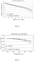
FIG. 4 is a 45°C cyclic graph of batteries with prepared separators in Example 1 and Comparative Example 1. -
FIG. 5 is a diagram of rate discharging of batteries with prepared separators in Example 1 and Comparative Example 1. -
FIG. 6 is a diagram of discharging of batteries with prepared separators at a low temperature of-20°C in Example 1 and Comparative Example 1. -
FIG. 7 is a diagram of aperture distribution of separators in Example 1 and Comparative Example 1. - The present disclosure is further described in detail with reference to specific embodiments below. It should be understood that the following embodiments merely illustrate and explain an example of the present disclosure, and should not be construed as limiting the protection scope of the present disclosure. All technologies implemented based on the foregoing content of the present disclosure are within the protection scope of the present disclosure.
- Experimental methods used in the following examples are all conventional methods unless otherwise specified, and reagents, materials, and the like that are used in the following examples may be all obtained from commercial sources unless otherwise specified.
- 20 kg aluminium oxide, 0.32 kg sodium carboxymethyl cellulose, 1 kg poly(methyl methacrylate), 0.1 kg polyvinylpyrrolidone, and 78.58 kg deionized water were mixed together to obtain ceramic slurry.
- 0.2 kg thermosensitive polymer microspheres (a particle size of the thermosensitive polymer microsphere is 1.5 µm, and a thermosensitive temperature is 110°C) were added to 10 kg of the foregoing ceramic slurry to obtain modified ceramic slurry.
- Microgravure coating was performed on a first surface of a separator base layer by using the foregoing modified ceramic slurry, followed by drying at 60°C for 1 min and processing at a high temperature of 120°C for 5 min, to obtain a separator.
- A thickness of the separator base layer in the separator is 9 µm. A material system of the separator base layer is PE. A porosity is 40%.
- A thickness of a ceramic coating in the separator is 3 µm. One or more of a surface and an interior of the ceramic coating have micropores. A porosity of the ceramic coating is 55%. Pores with apertures greater than 0.1 µm occupy 85%, and pores with apertures greater than 1 µm occupy 45%. A total surface density of the separator is 10.0 g/m2.
- A lithium-ion battery cell was prepared by using a method such as stacking or winding the foregoing separator, a positive electrode, and a negative electrode. A lithium-ion battery with high performance was obtained after baking, electrolyte filling, formation, and packaging.
- 20 kg aluminium oxide, 0.32 kg sodium carboxymethyl cellulose, 1 kg poly(methyl methacrylate), 0.1 kg polyvinylpyrrolidone, and 78.58 kg deionized water were mixed together to obtain ceramic slurry.
- 0.4 kg thermosensitive polymer microspheres (a particle size of the thermosensitive polymer microsphere is 1.5 µm, and a thermosensitive temperature is 110°C) were added to 10 kg of the foregoing ceramic slurry to obtain modified ceramic slurry.
- Microgravure coating was performed on a first surface of a separator base layer by using the foregoing modified ceramic slurry, followed by drying at 60°C for 1 min and processing at a high temperature of 122°C for 5 min, to obtain a separator.
- A thickness of the separator base layer in the separator is 9 µm. A material system of the separator base layer is PE. A porosity is 40%.
- A thickness of a ceramic coating in the separator is 3 µm. One or more of a surface and an interior of the ceramic coating have micropores. A porosity of the ceramic coating is 63%. Pores with apertures greater than 0.1 µm occupy 87%, and pores with apertures greater than 1 µm occupy 55%. A total surface density of the separator is 9.7g/m2.
- A lithium-ion battery cell was prepared by using a method such as stacking or winding the foregoing separator, a positive electrode, and a negative electrode. A lithium-ion battery with high performance was obtained after baking, electrolyte filling, formation, and packaging.
- 20 kg aluminium oxide, 0.32 kg sodium carboxymethyl cellulose, 1 kg poly(methyl methacrylate), 0.1 kg polyvinylpyrrolidone, and 78.58 kg deionized water were mixed together to obtain ceramic slurry.
- 0.6 kg thermosensitive polymer microspheres (a particle size of the thermosensitive polymer microsphere is 1.5 µm, and a thermosensitive temperature is 110°C) were added to 10 kg of the foregoing ceramic slurry to obtain modified ceramic slurry.
- Microgravure coating was performed on a first surface of a separator base layer by using the foregoing modified ceramic slurry, followed by drying at 60°C for 1 min and processing at a high temperature of 124°C for 5 min, to obtain a separator.
- A thickness of the separator base layer in the separator is 9 µm. A material system of the separator base layer is PE. A porosity is 40%.
- A thickness of a ceramic coating in the separator is 3 µm. One or more of a surface and an interior of the ceramic coating have micropores. A porosity of the ceramic coating is 70%. Pores with apertures greater than 0.1 µm occupy 89%, and pores with apertures greater than 1 µm occupy 65%. A total surface density of the separator is 9.4 g/m2.
- A lithium-ion battery cell was prepared by using a method such as stacking or winding the foregoing separator, a positive electrode, and a negative electrode. A lithium-ion battery with high performance was obtained after baking, electrolyte filling, formation, and packaging.
- 20 kg aluminium oxide, 0.32 kg sodium carboxymethyl cellulose, 1 kg poly(methyl methacrylate), 0.1 kg polyvinylpyrrolidone, and 78.58 kg deionized water were mixed together to obtain ceramic slurry.
- 0.4 kg thermosensitive polymer microspheres (a particle size of the thermosensitive polymer microsphere is 1.0 µm, and a thermosensitive temperature is 110°C) were added to 10 kg of the foregoing ceramic slurry to obtain modified ceramic slurry.
- Microgravure coating was performed on a first surface of a separator base layer by using the foregoing modified ceramic slurry, followed by drying at 60°C for 1 min and processing at a high temperature of 120°C for 7 min, to obtain a separator.
- A thickness of the separator base layer in the separator is 9 µm. A material system of the separator base layer is PE. A porosity is 40%.
- A thickness of a ceramic coating in the separator is 3 µm. One or more of a surface and an interior of the ceramic coating have micropores. A porosity of the ceramic coating is 60%. Pores with apertures greater than 0.1 µm occupy 88%, and pores with apertures greater than 1 µm occupy 50%. A total surface density of the separator is 9.8g/m2.
- A lithium-ion battery cell was prepared by using a method such as stacking or winding the foregoing separator, a positive electrode, and a negative electrode. A lithium-ion battery with high performance was obtained after baking, electrolyte filling, formation, and packaging.
- 20 kg aluminium oxide, 0.32 kg sodium carboxymethyl cellulose, 1 kg poly(methyl methacrylate), 0.1 kg polyvinylpyrrolidone, and 78.58 kg deionized water were mixed together to obtain ceramic slurry.
- 0.6 kg thermosensitive polymer microspheres (a particle size of the thermosensitive polymer microsphere is 0.5 µm, and a thermosensitive temperature is 110°C) were added to 10 kg of the foregoing ceramic slurry to obtain modified ceramic slurry.
- Microgravure coating was performed on a first surface of a separator base layer by using the foregoing modified ceramic slurry, followed by drying at 60°C for 1 min and processing at a high temperature of 118°C for 9 min, to obtain a separator.
- A thickness of the separator base layer in the separator is 9 µm. A material system of the separator base layer is PE. A porosity is 40%.
- A thickness of a ceramic coating in the separator is 3 µm. One or more of a surface and an interior of the ceramic coating have micropores. A porosity of the ceramic coating is 72%. Pores with apertures greater than 0.1 µm occupy 90%, and pores with apertures greater than 1 µm occupy 55%. A total surface density of the separator is 9.5g/m2.
- A lithium-ion battery cell was prepared by using a method such as stacking or winding the foregoing separator, a positive electrode, and a negative electrode. A lithium-ion battery with high performance was obtained after baking, electrolyte filling, formation, and packaging.
- 20 kg aluminium oxide, 0.32 kg sodium carboxymethyl cellulose, 1 kg poly(methyl methacrylate), 0.1 kg polyvinylpyrrolidone, and 78.58 kg deionized water were mixed together to obtain ceramic slurry.
- 0.2 kg thermosensitive polymer microspheres (a particle size of the thermosensitive polymer microsphere is 1.0 µm, and a thermosensitive temperature is 100°C) were added to 10 kg of the foregoing ceramic slurry to obtain modified ceramic slurry.
- Microgravure coating was performed on a first surface of a separator base layer by using the foregoing modified ceramic slurry, followed by drying at 60°C for 1 min and processing at a high temperature of 120°C for 7 min, to obtain a separator.
- A thickness of the separator base layer in the separator is 9 µm. A material system of the separator base layer is PE. A porosity is 40%.
- A thickness of a ceramic coating in the separator is 3 µm. One or more of a surface and an interior of the ceramic coating have micropores. A porosity of the ceramic coating is 55%. Pores with apertures greater than 0.1 µm occupy 85%, and pores with apertures greater than 1 µm occupy 40%. A total surface density of the separator is 10.0 g/m2.
- A lithium-ion battery cell was prepared by using a method such as stacking or winding the foregoing separator, a positive electrode, and a negative electrode. A lithium-ion battery with high performance was obtained after baking, electrolyte filling, formation, and packaging.
- 20 kg aluminium oxide, 0.32 kg sodium carboxymethyl cellulose, 1 kg poly(methyl methacrylate), 0.1 kg polyvinylpyrrolidone, and 78.58 kg deionized water were mixed together to obtain ceramic slurry.
- 0.2 kg thermosensitive polymer microspheres (a particle size of the thermosensitive polymer microsphere is 1.0 µm, and a thermosensitive temperature is 120°C) were added to 10 kg of the foregoing ceramic slurry to obtain modified ceramic slurry.
- Microgravure coating was performed on a first surface of a separator base layer by using the foregoing modified ceramic slurry, followed by drying at 60°C for 1 min and processing at a high temperature of 130°C for 4 min, to obtain a separator.
- A thickness of the separator base layer in the separator is 9 µm. A material system of the separator base layer is PE. A porosity is 40%.
- A thickness of a ceramic coating in the separator is 3 µm. One or more of a surface and an interior of the ceramic coating have micropores. A porosity of the ceramic coating is 55%. Pores with apertures greater than 0.1 µm occupy 85%, and pores with apertures greater than 1 µm occupy 40%. A total surface density of the separator is 10.0 g/m2.
- A lithium-ion battery cell was prepared by using a method such as stacking or winding the foregoing separator, a positive electrode, and a negative electrode. A lithium-ion battery with high performance was obtained after baking, electrolyte filling, formation, and packaging.
- 20 kg aluminium oxide, 0.32 kg sodium carboxymethyl cellulose, 1 kg poly(methyl methacrylate), 0.1 kg polyvinylpyrrolidone, and 78.58 kg deionized water were mixed together to obtain ceramic slurry.
- Microgravure coating was performed on a first surface of a separator base layer by using the foregoing modified ceramic slurry, followed by drying at 60°C for 1 min, to obtain a separator.
- A thickness of the separator base layer in the separator is 9 µm. A material system of the separator base layer is PE. A porosity is 40%.
- A thickness of a ceramic coating in the separator is 3 µm. One or more of a surface and an interior of the ceramic coating have micropores. A porosity of the ceramic coating is 30%. Pores with apertures greater than 0.1 µm occupy 60%, and pores with apertures greater than 1 µm occupy 15%. A total surface density of the separator is 10.0 g/m2.
- A lithium-ion battery cell was prepared by using a method such as stacking or winding the foregoing separator, a positive electrode, and a negative electrode. A lithium-ion battery with high performance was obtained after baking, electrolyte filling, formation, and packaging.
- A voltage test and an internal resistance test were performed on the lithium-ion batteries prepared in Examples 1 to 7 and Comparative Example 1. A test process was as follows: the lithium-ion batteries prepared in Examples 1 to 7 and Comparative Example 1 were fully charged and then placed in an environment at 25°C in 50% humidity. A voltage and internal resistance meter (Applent-Applent, Model: AT526B) was used to test a voltage and an internal resistance of the battery in a fully charged state. Results are shown in Table 1.
Table 1: Results of the voltage test and internal resistance test for the lithium-ion batteries in Examples 1 to 7 and Comparative Example 1 Sample number Average voltage of the lithium-ion battery Internal resistance of the lithium-ion battery Example 1 4.2011 V 10.23 mΩ Example 2 4.2022 V 9.67 mΩ Example 3 4.2017 V 8.42 mΩ Example 4 4.2015 V 9.88 mΩ Example 5 4.2009 V 7.75 mΩ Example 6 4.2012 V 10.33 mΩ Example 7 4.2022 V 10.28 mΩ Comparative Example 1 4.2015 V 12.55 mΩ - It is learned from data in Table 1 that, after the lithium-ion batteries prepared in Examples 1 to 7 and Comparative Example 1 are sorted, the voltages are normal. However, internal resistances of the lithium-ion batteries prepared in Examples 1 to 7 are significantly reduced in comparison with that of the lithium-ion battery prepared in Comparative Example 1. This is mainly because permeability of lithium ions can be significantly improved due to high porosities of the separators prepared in Examples 1 to 7. In addition, significant reduction in the internal resistance also helps improve rate performance, low-temperature discharging performance, and long cycling performance of the battery.
- A charge-discharge cycle test and a rate performance test were performed on the lithium-ion batteries prepared in Example 1 and Comparative Example 1. The charge-discharge cycle test was performed by using a 1C charging system/a 1C discharging system. The rate performance test was performed by using a 0.2C charging system/a 0.2C, 0.5C, 1C, 1.5C, or 2C discharging system. Results are shown in
FIG. 4 and FIG. 5 . It may be learned fromFIG. 4 and FIG. 5 that the battery in Example 1 may maintain a good capacity retention in a latter period of the cycle and may also maintain a good capacity retention during high rate discharging. - Experimental results of Examples 1 to 7 and Comparative Example 1 are compared to obtain the following conclusions:
- (1) As the porosity of the ceramic coating increases, the internal resistance of the battery can be reduced, and the rate performance and the cycling performance of the battery can be improved.
- (2) In Examples 1 to 7, as the porosity increases, the internal resistance of the battery is significantly decreased.
- Residual liquid volumes of the lithium-ion batteries prepared in Examples 1 to 7 and Comparative Example 1 were tested. A separator nail penetration strength and an ionic conductivity were tested for the separators of the lithium-ion batteries prepared in Examples 1 to 7 and Comparative Example 1.
- The residual liquid volume was mainly obtained through measuring a weight M1 of a battery cell before electrolyte filling, an edge trimming weight M2, and a weight M3 of the cell after a second time of packaging, to obtain the residual liquid volume M3+M2-M1. A method for measuring the nail penetration strength was as follows: penetrating the separator at a speed of 100 mm/min by using a steel nail including a spherical nail head with a diameter of 1 mm. In a penetration process, a maximum force was recorded as the nail penetration strength. A method for testing the ionic conductivity was as follows: placing a sample into an electrolyte at a temperature of 23±2°C, to keep sealed and soaked for 2 h; injecting the electrolyte into a resistance test mold, connecting the resistance test mold to a chemical workstation, and setting test parameters; placing one layer of a separator and testing impedance spectroscopy of this layer, placing another layer and testing impedance spectroscopy of this layer until four layers are placed, obtaining four impedance spectroscopy images through measurement, and separately reading resistance values R1, R2, R3, and R4 of the first layer to the fourth layer from the impedance spectroscopy images; and drawing a curve by using a layer number as a horizontal coordinate and a separator resistance value as a vertical coordinate, and obtaining a slope and a linear fitting degree of the curve. When the linear fitting degree is greater than 0.99, the ionic conductivity of the separator is calculated according to the following formula:

- σ denotes an ionic conductivity of a sample in units of siemens/centimeter (S/cm), d denotes a thickness of a sample in units of microns (µm), k denotes a slope of a curve, and S denotes a test area of a separator in units of square centimeters (cm2).
Table 2: Test results of residual liquid volumes, separator nail penetration strengths of the separators, and ionic conductivities of the lithium-ion batteries prepared in Examples 1 to 7 and Comparative Example 1 Residual liquid volume ∗g Ionic conductivity ∗10-4Scm-1Separator nail penetration strength g Example 1 7.978 10.66 528 Example 2 8.109 12.45 535 Example 3 8.411 13.74 510 Example 4 8.045 11.98 518 Example 5 8.604 15.79 507 Example 6 7.898 10.53 502 Example 7 7.935 9.86 498 Comparative Example 1 7.503 3.64 511 - It may be learned from the test results that the residual liquid volumes in the separators of Examples 1 to 7 are improved to some extent. This is mainly because the porosity of the separator increases, and there is more space for storing the electrolyte. In addition, ionic conductivities of the separators in Examples 1 to 7 are significantly increased. This is mainly because the porosity of the ceramic coating made of a porous material is significantly increased. Therefore, it may also be indicated that long cycling performance, rate performance, and low temperature performance of the battery may be significantly improved because of the separators in Examples 1 to 7. The nail penetration strength test performed on the separators in Examples 1 to 7 has equivalent results as the nail penetration strength test performed on the separator in Comparative Example 1. This indicates that the separator in the present disclosure may meet a requirement for the nail penetration strength, and a relatively good safety performance is obtained.
- The implementations of the present disclosure are described above. However, the present disclosure is not limited to the foregoing implementations. Any modification, equivalent replacement, or improvement made without departing from the spirit and the principle of the present disclosure shall fall within the protection scope of the present disclosure.
Claims (22)
- A separator, characterized by comprising a separator base layer and a ceramic coating disposed on a first surface of the separator base layer; wherein the ceramic coating comprises ceramic particles; a surface and/or an interior of the ceramic coating has micropores; a porosity of the ceramic coating ranges from 40% to 80%; in the micropores, a volume of pores with apertures greater than 0.1 microns occupies 45%-90% of a total pore volume; and a volume of pores with apertures greater than 1.0 micron occupies 40%-80% of the total pore volume.
- The separator according to claim 1, characterized in that an aperture of the largest pore in the micropores does not exceed 10 microns, and/or
an aperture of the smallest pore in the micropores is not less than 0.01 microns. - The separator according to claim 1 or 2, characterized in that a total surface density of the separator ranges from 9.4 g/m2 to 10.0 g/m2.
- The separator according to any one of claims 1 to 3, characterized in that a material system of the separator base layer is selected from at least one of polyethylene, polypropylene, polyethylene terephthalate, polybutylene terephthalate, polystyrene, a polynaphthalene system polymer, polyimide, aromatic polyamide fiber, or poly (p-phenylenebenzobisoxazole).
- The separator according to any one of claims 1 to 4, characterized in that a porosity of the separator base layer ranges from 20% to 80%.
- The separator according to any one of claims 1 to 5, characterized in that a thickness of the separator base layer ranges from 5 µm to 50 µm.
- The separator according to claim 1, characterized in that an addition amount of the ceramic particles is 80wt%-97wt% of a total mass of the ceramic coating.
- The separator according to claim 1 or 7, characterized in that the ceramic coating further comprises an additive, and the additive comprises a binder, a thickener, and a dispersing agent.
- The separator according to claim 8, characterized in that an addition amount of the binder is 1 wt%-10wt% of the total mass of the ceramic coating, an addition amount of the thickener is 1wt%-10wt% of the total mass of the ceramic coating, and an addition amount of the dispersing agent is 1 wt%-5wt% of the total mass of the ceramic coating.
- The separator according to any one of claims 1 to 9, characterized in that a large quantity of micropores exist in the surface and/or the interior of the ceramic coating, formation of the micropores is adding a thermosensitive polymer to slurry for preparing the ceramic coating, performing heat treatment through a drying process, and then preparing the ceramic coating with the large quantity of micropores in the surface and/or the interior, the thermosensitive polymer is fused and then separated from a system in a heat treatment process, and the large quantity of micropores exist in the surface and/or the interior of the ceramic coating.
- The separator according to any one of claims 1 to 9, characterized in that the ceramic coating is obtained by using the following preparation method:
adding the thermosensitive polymer to the slurry for preparing the ceramic coating, and then obtaining the ceramic coating after drying and heat treatment. - The separator according to claim 10 or 11, characterized in that the thermosensitive polymer is selected from at least one of polyethylene, polystyrene, poly(methyl methacrylate), poly(acrylic acid-co-butadiene-co-styrene), polylactic acid, polyvinyl chloride, polyvinyl butyral, a monomer-modified copolymerized polymer thereof, or the like.
- The separator according to any one of claims 10 to 12, characterized in that the thermosensitive polymer is thermosensitive polymer microspheres, and a particle size of the thermosensitive polymer microsphere ranges from 0.01 µm to 10 µm.
- The separator according to any one of claims 10 to 13, characterized in that a melting point of the thermosensitive polymer ranges from 60°C to 150°C.
- The separator according to any one of claims 11 to 14, characterized in that a drying temperature ranges from 40°C to 120°C, and a drying time ranges from 20s to 600s.
- The separator according to any one of claims 11 to 15, characterized in that a heat treatment temperature is 0°C-20°C higher than the melting point of the thermosensitive polymer, and a heat treatment time ranges from 2 min to 10 min.
- The separator according to any one of claims 10 to 16, characterized in that a weight ratio of the thermosensitive polymer to the ceramic particles is (1-60):(99-40) in the slurry for preparing the ceramic coating.
- The separator according to any one of claims 1 to 17, characterized in that the thickness of the ceramic coating ranges from 1 µm to 10 µm.
- The separator according to any one of claims 1 to 18, characterized in that a median particle size of the ceramic particles ranges from 0.01 µm to 10 µm.
- The separator according to any one of claims 1 to 19, characterized in that the separator further comprises a first binder coating layer disposed on a surface of the ceramic coating, and/or
the separator further comprises a second binder coating layer disposed on a second surface, opposite to a first surface, of the separator base layer. - The separator according to claim 20, characterized in that the first binder coating layer and the second binder coating layer have a same thickness or different thicknesses selected from a range of 1 µm-5 µm.
- A lithium-ion battery, characterized in that the lithium-ion battery comprises the separator according to any one of claims 1 to 21.
Applications Claiming Priority (2)
| Application Number | Priority Date | Filing Date | Title |
|---|---|---|---|
| CN202010975419.4A CN112018312A (en) | 2020-09-16 | 2020-09-16 | Diaphragm and battery comprising same |
| PCT/CN2021/116800 WO2022057674A1 (en) | 2020-09-16 | 2021-09-06 | Diaphragm, and battery comprising same |
Publications (2)
| Publication Number | Publication Date |
|---|---|
| EP4156401A1 true EP4156401A1 (en) | 2023-03-29 |
| EP4156401A4 EP4156401A4 (en) | 2024-12-25 |
Family
ID=73522988
Family Applications (1)
| Application Number | Title | Priority Date | Filing Date |
|---|---|---|---|
| EP21868499.1A Pending EP4156401A4 (en) | 2020-09-16 | 2021-09-06 | MEMBRANE AND BATTERY |
Country Status (4)
| Country | Link |
|---|---|
| US (1) | US20230125852A1 (en) |
| EP (1) | EP4156401A4 (en) |
| CN (1) | CN112018312A (en) |
| WO (1) | WO2022057674A1 (en) |
Families Citing this family (9)
| Publication number | Priority date | Publication date | Assignee | Title |
|---|---|---|---|---|
| CN112018312A (en) * | 2020-09-16 | 2020-12-01 | 珠海冠宇电池股份有限公司 | Diaphragm and battery comprising same |
| CN112787051B (en) * | 2021-01-25 | 2022-10-21 | 远景动力技术(江苏)有限公司 | Method for improving coefficient of residual liquid of battery cell |
| CN114142167B (en) * | 2021-11-30 | 2023-05-02 | 珠海冠宇电池股份有限公司 | Diaphragm and lithium ion battery containing same |
| CN114759312B (en) * | 2022-06-15 | 2022-10-18 | 宁德卓高新材料科技有限公司 | Ceramic diaphragm and preparation method and application thereof |
| CN115347319B (en) * | 2022-07-01 | 2024-03-26 | 上海兰钧新能源科技有限公司 | Battery isolating film for improving JR deformation and preparation method and application thereof |
| CN116333554B (en) * | 2023-05-29 | 2023-11-03 | 宁德时代新能源科技股份有限公司 | Coating composition for isolating film, composite isolating film, battery cell, battery and electric equipment |
| TW202526394A (en) * | 2023-11-08 | 2025-07-01 | 以色列商魯姆斯有限公司 | Folded 2d expansion optical waveguide |
| WO2026044080A1 (en) * | 2024-08-21 | 2026-02-26 | Sila Nanotechnologies, Inc. | Highly-porous elongate ceramic particles for transition metal gettering in batteries |
| CN119153896B (en) * | 2024-11-12 | 2025-03-18 | 珠海冠宇动力电池有限公司 | Diaphragm and battery |
Family Cites Families (8)
| Publication number | Priority date | Publication date | Assignee | Title |
|---|---|---|---|---|
| TWI318018B (en) * | 2004-09-02 | 2009-12-01 | Lg Chemical Ltd | Organic/inorganic composite porous film and electrochemical device prepared thereby |
| KR100775310B1 (en) * | 2004-12-22 | 2007-11-08 | 주식회사 엘지화학 | Organic/inorganic composite microporous membrane and electrochemical device prepared thereby |
| CN103947008B (en) * | 2011-11-15 | 2017-12-01 | 丰田自动车株式会社 | Nonaqueous electrolyte type secondary cell |
| KR102050024B1 (en) * | 2015-03-10 | 2019-11-28 | 주식회사 엘지화학 | Method for preparing separator of secondary battery and separator prepared by using the same |
| WO2019126977A1 (en) * | 2017-12-26 | 2019-07-04 | 广州华创化工材料科技开发有限公司 | Battery separator, preparation method therefor and use |
| CN115528379A (en) * | 2018-04-11 | 2022-12-27 | 宁德新能源科技有限公司 | Isolating membrane and energy storage device |
| CN111224045A (en) * | 2018-11-27 | 2020-06-02 | 佛山市盈博莱科技股份有限公司 | Ceramic composite diaphragm with thermal shutdown function and preparation method thereof |
| CN112018312A (en) * | 2020-09-16 | 2020-12-01 | 珠海冠宇电池股份有限公司 | Diaphragm and battery comprising same |
-
2020
- 2020-09-16 CN CN202010975419.4A patent/CN112018312A/en active Pending
-
2021
- 2021-09-06 WO PCT/CN2021/116800 patent/WO2022057674A1/en not_active Ceased
- 2021-09-06 EP EP21868499.1A patent/EP4156401A4/en active Pending
-
2022
- 2022-12-27 US US18/146,598 patent/US20230125852A1/en active Pending
Also Published As
| Publication number | Publication date |
|---|---|
| US20230125852A1 (en) | 2023-04-27 |
| EP4156401A4 (en) | 2024-12-25 |
| CN112018312A (en) | 2020-12-01 |
| WO2022057674A1 (en) | 2022-03-24 |
Similar Documents
| Publication | Publication Date | Title |
|---|---|---|
| EP4156401A1 (en) | Diaphragm, and battery comprising same | |
| EP4086982A1 (en) | Positive electrode plate and lithium ion battery | |
| US11050052B2 (en) | Lithium ion battery and negative electrode material thereof | |
| US12388113B2 (en) | Diaphragm and high-voltage battery comprising same | |
| US11177475B2 (en) | Ternary positive electrode material, and lithium ion battery | |
| CN111653717B (en) | Preparation method of composite diaphragm, composite diaphragm and lithium ion battery | |
| US12555778B2 (en) | Negative electrode plate and lithium-ion battery | |
| EP1994586B1 (en) | Lithium secondary battery with enhanced heat-resistance | |
| EP4274016A2 (en) | Organic/inorganic composite microporous membrane and electrochemical device | |
| CN110416472B (en) | Mesoporous silica microsphere lithium ion battery separator and lithium ion battery | |
| CN113921986A (en) | Composite diaphragm and battery comprising same | |
| US20210175483A1 (en) | Ceramic separator and method for manufacturing thereof | |
| WO2007094641A1 (en) | Organic/inorganic composite electrolyte and electrochemical device prepared thereby | |
| CN114024100A (en) | Separator for nonaqueous electrolyte lithium secondary battery and nonaqueous electrolyte lithium secondary battery | |
| TW201351758A (en) | Isolation film of electrochemical device and manufacturing method thereof | |
| CN112531291A (en) | Ceramic microsphere, diaphragm containing ceramic microsphere and lithium ion battery containing diaphragm | |
| CN106848162A (en) | Secondary battery | |
| CN116435713B (en) | Diaphragm and battery comprising same | |
| CN108695475A (en) | Lithium ion battery separator and lithium ion battery | |
| CN108023051A (en) | A kind of isolation film and the lithium ion battery containing the isolation film | |
| CN105098161A (en) | Nickel-based multi-element cathode material of lithium ion battery and preparation method of nickel-based multi-element cathode material | |
| CN112864352A (en) | Pole piece and lithium ion battery | |
| CN114050225A (en) | An electrode pole piece and a lithium ion battery containing the electrode pole piece | |
| CN112615110B (en) | Metal-ceramic microsphere, diaphragm containing metal-ceramic microsphere and lithium ion battery containing diaphragm | |
| US12021257B2 (en) | Separator, method of manufacturing the separator, and electrochemical device including the separator |
Legal Events
| Date | Code | Title | Description |
|---|---|---|---|
| STAA | Information on the status of an ep patent application or granted ep patent |
Free format text: STATUS: THE INTERNATIONAL PUBLICATION HAS BEEN MADE |
|
| PUAI | Public reference made under article 153(3) epc to a published international application that has entered the european phase |
Free format text: ORIGINAL CODE: 0009012 |
|
| STAA | Information on the status of an ep patent application or granted ep patent |
Free format text: STATUS: REQUEST FOR EXAMINATION WAS MADE |
|
| 17P | Request for examination filed |
Effective date: 20221223 |
|
| AK | Designated contracting states |
Kind code of ref document: A1 Designated state(s): AL AT BE BG CH CY CZ DE DK EE ES FI FR GB GR HR HU IE IS IT LI LT LU LV MC MK MT NL NO PL PT RO RS SE SI SK SM TR |
|
| R17P | Request for examination filed (corrected) |
Effective date: 20221223 |
|
| RBV | Designated contracting states (corrected) |
Designated state(s): AL AT BE BG CH CY CZ DE DK EE ES FI FR GB GR HR HU IE IS IT LI LT LU LV MC MK MT NL NO PL PT RO RS SE SI SK SM TR |
|
| DAV | Request for validation of the european patent (deleted) | ||
| DAX | Request for extension of the european patent (deleted) | ||
| A4 | Supplementary search report drawn up and despatched |
Effective date: 20241121 |
|
| RIC1 | Information provided on ipc code assigned before grant |
Ipc: H01M 50/431 20210101ALI20241115BHEP Ipc: H01M 50/449 20210101ALI20241115BHEP Ipc: H01M 50/489 20210101ALI20241115BHEP Ipc: H01M 50/491 20210101AFI20241115BHEP |
|
| STAA | Information on the status of an ep patent application or granted ep patent |
Free format text: STATUS: EXAMINATION IS IN PROGRESS |
|
| 17Q | First examination report despatched |
Effective date: 20250711 |