EP4155864B1 - Elektronische vorrichtung mit flexibler anzeige - Google Patents
Elektronische vorrichtung mit flexibler anzeige Download PDFInfo
- Publication number
- EP4155864B1 EP4155864B1 EP21900854.7A EP21900854A EP4155864B1 EP 4155864 B1 EP4155864 B1 EP 4155864B1 EP 21900854 A EP21900854 A EP 21900854A EP 4155864 B1 EP4155864 B1 EP 4155864B1
- Authority
- EP
- European Patent Office
- Prior art keywords
- electronic device
- driving
- state
- bar
- flexible display
- Prior art date
- Legal status (The legal status is an assumption and is not a legal conclusion. Google has not performed a legal analysis and makes no representation as to the accuracy of the status listed.)
- Active
Links
Images


Classifications
-
- H—ELECTRICITY
- H04—ELECTRIC COMMUNICATION TECHNIQUE
- H04M—TELEPHONIC COMMUNICATION
- H04M1/00—Substation equipment, e.g. for use by subscribers
- H04M1/02—Constructional features of telephone sets
- H04M1/0202—Portable telephone sets, e.g. cordless phones, mobile phones or bar type handsets
- H04M1/0206—Portable telephones comprising a plurality of mechanically joined movable body parts, e.g. hinged housings
- H04M1/0208—Portable telephones comprising a plurality of mechanically joined movable body parts, e.g. hinged housings characterized by the relative motions of the body parts
- H04M1/0235—Slidable or telescopic telephones, i.e. with a relative translation movement of the body parts; Telephones using a combination of translation and other relative motions of the body parts
- H04M1/0237—Sliding mechanism with one degree of freedom
-
- H—ELECTRICITY
- H05—ELECTRIC TECHNIQUES NOT OTHERWISE PROVIDED FOR
- H05K—PRINTED CIRCUITS; CASINGS OR CONSTRUCTIONAL DETAILS OF ELECTRIC APPARATUS; MANUFACTURE OF ASSEMBLAGES OF ELECTRICAL COMPONENTS
- H05K5/00—Casings, cabinets or drawers for electric apparatus
- H05K5/02—Details
- H05K5/0217—Mechanical details of casings
-
- G—PHYSICS
- G06—COMPUTING OR CALCULATING; COUNTING
- G06F—ELECTRIC DIGITAL DATA PROCESSING
- G06F1/00—Details not covered by groups G06F3/00 - G06F13/00 and G06F21/00
- G06F1/16—Constructional details or arrangements
-
- G—PHYSICS
- G06—COMPUTING OR CALCULATING; COUNTING
- G06F—ELECTRIC DIGITAL DATA PROCESSING
- G06F1/00—Details not covered by groups G06F3/00 - G06F13/00 and G06F21/00
- G06F1/16—Constructional details or arrangements
- G06F1/1613—Constructional details or arrangements for portable computers
- G06F1/1615—Constructional details or arrangements for portable computers with several enclosures having relative motions, each enclosure supporting at least one I/O or computing function
- G06F1/1624—Constructional details or arrangements for portable computers with several enclosures having relative motions, each enclosure supporting at least one I/O or computing function with sliding enclosures, e.g. sliding keyboard or display
-
- G—PHYSICS
- G06—COMPUTING OR CALCULATING; COUNTING
- G06F—ELECTRIC DIGITAL DATA PROCESSING
- G06F1/00—Details not covered by groups G06F3/00 - G06F13/00 and G06F21/00
- G06F1/16—Constructional details or arrangements
- G06F1/1613—Constructional details or arrangements for portable computers
- G06F1/1633—Constructional details or arrangements of portable computers not specific to the type of enclosures covered by groups G06F1/1615 - G06F1/1626
- G06F1/1637—Details related to the display arrangement, including those related to the mounting of the display in the housing
- G06F1/1652—Details related to the display arrangement, including those related to the mounting of the display in the housing the display being flexible, e.g. mimicking a sheet of paper, or rollable
-
- G—PHYSICS
- G09—EDUCATION; CRYPTOGRAPHY; DISPLAY; ADVERTISING; SEALS
- G09F—DISPLAYING; ADVERTISING; SIGNS; LABELS OR NAME-PLATES; SEALS
- G09F9/00—Indicating arrangements for variable information in which the information is built-up on a support by selection or combination of individual elements
- G09F9/30—Indicating arrangements for variable information in which the information is built-up on a support by selection or combination of individual elements in which the desired character or characters are formed by combining individual elements
-
- H—ELECTRICITY
- H05—ELECTRIC TECHNIQUES NOT OTHERWISE PROVIDED FOR
- H05K—PRINTED CIRCUITS; CASINGS OR CONSTRUCTIONAL DETAILS OF ELECTRIC APPARATUS; MANUFACTURE OF ASSEMBLAGES OF ELECTRICAL COMPONENTS
- H05K5/00—Casings, cabinets or drawers for electric apparatus
- H05K5/0017—Casings, cabinets or drawers for electric apparatus with operator interface units
-
- H—ELECTRICITY
- H04—ELECTRIC COMMUNICATION TECHNIQUE
- H04M—TELEPHONIC COMMUNICATION
- H04M1/00—Substation equipment, e.g. for use by subscribers
- H04M1/02—Constructional features of telephone sets
- H04M1/0202—Portable telephone sets, e.g. cordless phones, mobile phones or bar type handsets
- H04M1/026—Details of the structure or mounting of specific components
- H04M1/0266—Details of the structure or mounting of specific components for a display module assembly
- H04M1/0268—Details of the structure or mounting of specific components for a display module assembly including a flexible display panel
Definitions
- Electronic devices are gradually becoming slimmer, and are being improved to increase rigidity, strengthen design, and differentiate functional elements thereof. Electronic devices are being transformed from a uniform rectangular shape into a variety of shapes. Electronic devices may have a deformable structure enabling use of a large-screen display while providing convenient portability. For example, as an example of a deformable structure, an electronic device may have a structure in which the display area of a flexible display can be varied by supporting housings that slide with respect to each other (e.g., a rollable structure or a slidable structure).
- a rollable electronic device (or a slidable electronic device) may be configured such that a flexible display can be rolled up or unfolded, and a slidable electronic device may be configured such that a flexible display moves in a sliding manner, thereby expanding and contracting a screen.
- US 10 747 269 B1 and US 2019/268455 A1 disclose conventional electronic devices including a flexible display, wherein the flexible display is enabled to slide while switching from the first state to the second state.
- An electronic device may include a rollable electronic device (e.g., a slidable electronic device) in which the display area of a display can be expanded and/or reduced.
- the rollable electronic device may include a first housing (e.g., a first housing structure, a base housing, a base bracket, or a base structure) and a second housing (e.g., a second housing, a slide housing, a slide bracket, or a slide structure), which are coupled to each other to move relative to each other so as to be at least partially fitted together with each other.
- first housing and the second housing may operate to slide with respect to each other, and support and guide at least a portion of a flexible display (e.g., an expandable display or a stretchable display) such that the flexible display has a first display area in a slide-in state and such that the flexible display has a second display area, which is greater than the first display area, in a slide-out state.
- a flexible display e.g., an expandable display or a stretchable display
- the rollable electronic device may include a bendable member (e.g., a multi-bar assembly) for supporting at least a portion of the flexible display when the second housing moves by a specified distance from the first housing. At least a portion of the flexible display, when the electronic device is in a slide-in state, may slide in the inner space of the first housing or the inner space of the second housing to be bent while being supported by a bendable member.
- the electronic device may include at least one pressing member (e.g., a sliding frame) for pressing the rear surface of the bendable member in a slide-out direction while the electronic device is switching from the slide-in state to the slide-out state.
- an aspect of the disclosure is to provide an electronic device including a flexible display capable of reducing frictional force between a bendable member supporting the flexible display and a pressing member pressing the same.
- Another aspect of the disclosure is to provide an electronic device including a flexible display capable of providing an efficient driving force according to sliding-in/sliding-out by reducing the frictional force between the bendable member and the pressing member and helping in reducing noise.
- the plurality of driving bodies comprises a first driving bar rotatably coupled to the sliding bar, a second driving bar rotatably coupled to the case, a driving shaft configured to couple the first driving bar and the second driving bar to be movable, and an elastic member configured to press the first driving bar and the second driving bar to be unfolded at a predetermined angle with respect to each other.
- the guide slits on a first side of the center of the sliding frame, among the plurality of first guide slits, are formed to have a predetermined curvature in a first direction, and the guide slits on a second side thereof are formed to have a predetermined curvature in a second direction opposite the first direction.
- the driving shafts of the plurality of driving bodies are at least partially inserted into the plurality of first guide slits and move along curves of the plurality of first guide slits.
- An electronic device may reduce friction between components supporting expansion and contraction of a screen when the screen of the display is expanded or contracted, thereby reducing the power required for expansion and contraction of the screen of the display.
- FIG. 1 illustrates an electronic device in a network environment according to an embodiment of the disclosure.
- an electronic device 101 in a network environment 100 may communicate with an electronic device 102 via a first network 198 (e.g., a short-range wireless communication network), or an electronic device 104 or a server 108 via a second network 199 (e.g., a long-range wireless communication network).
- the electronic device 101 may communicate with the electronic device 104 via the server 108.
- the electronic device 101 includes a processor 120, memory 130, an input device 150, an audio output device 155, a display device 160, an audio module 170, a sensor module 176, an interface 177, a haptic module 179, a camera module 180, a power management module 188, a battery 189, a communication module 190, a subscriber identification module (SIM) 196, or an antenna module 197.
- at least one (e.g., the display device 160 or the camera module 180) of the components may be omitted from the electronic device 101, or one or more other components may be added in the electronic device 101.
- some of the components may be implemented as single integrated circuitry.
- the sensor module 176 e.g., a fingerprint sensor, an iris sensor, or an illuminance sensor
- the display device 160 e.g., a display.
- the processor 120 may execute, for example, software (e.g., a program 140) to control at least one other component (e.g., a hardware or software component) of the electronic device 101 coupled with the processor 120, and may perform various data processing or computation. As at least part of the data processing or computation, the processor 120 may load a command or data received from another component (e.g., the sensor module 176 or the communication module 190) in volatile memory 132, process the command or the data stored in the volatile memory 132, and store resulting data in non-volatile memory 134.
- software e.g., a program 140
- the processor 120 may load a command or data received from another component (e.g., the sensor module 176 or the communication module 190) in volatile memory 132, process the command or the data stored in the volatile memory 132, and store resulting data in non-volatile memory 134.
- the processor 120 may include a main processor 121 (e.g., a central processing unit (CPU) or an application processor (AP)), and an auxiliary processor 123 (e.g., a graphics processing unit (GPU), an image signal processor (ISP), a sensor hub processor, or a communication processor (CP)) that is operable independently from, or in conjunction with, the main processor 121. Additionally, or alternatively, the auxiliary processor 123 may be adapted to consume less power than the main processor 121, or to be specific to a specified function. The auxiliary processor 123 may be implemented as separate from, or as part of the main processor 121.
- auxiliary processor 123 e.g., a graphics processing unit (GPU), an image signal processor (ISP), a sensor hub processor, or a communication processor (CP)
- the auxiliary processor 123 may be adapted to consume less power than the main processor 121, or to be specific to a specified function.
- the auxiliary processor 123 may be implemented as separate from, or as part of the
- the auxiliary processor 123 may control at least some of functions or states related to at least one component (e.g., the display device 160, the sensor module 176, or the communication module 190) among the components of the electronic device 101, instead of the main processor 121 while the main processor 121 is in an inactive (e.g., sleep) state, or together with the main processor 121 while the main processor 121 is in an active state (e.g., executing an application).
- the auxiliary processor 123 e.g., an ISP or a CP
- the memory 130 may store various data used by at least one component (e.g., the processor 120 or the sensor module 176) of the electronic device 101.
- the various data may include, for example, software (e.g., the program 140) and input data or output data for a command related thereto.
- the memory 130 may include the volatile memory 132 or the non-volatile memory 134.
- the non-volatile memory 134 may include internal memory 136 and external memory 138.
- the program 140 may be stored in the memory 130 as software, and may include, for example, an operating system (OS) 142, middleware 144, or an application 146.
- OS operating system
- middleware middleware
- application application
- the input device 150 may receive a command or data to be used by another component (e.g., the processor 120) of the electronic device 101, from the outside (e.g., a user) of the electronic device 101.
- the input device 150 may include, for example, a microphone, a mouse, a keyboard, or a digital pen (e.g., a stylus pen).
- the audio output device 155 may output sound signals to the outside of the electronic device 101.
- the audio output device 155 may include, for example, a speaker or a receiver.
- the speaker may be used for general purposes, such as playing multimedia or playing record, and the receiver may be used for an incoming calls.
- the receiver may be implemented as separate from, or as part of the speaker.
- the display device 160 may visually provide information to the outside (e.g., a user) of the electronic device 101.
- the display device 160 may include, for example, a display, a hologram device, or a projector and control circuitry to control a corresponding one of the display, hologram device, and projector.
- the display device 160 may include touch circuitry adapted to detect a touch, or sensor circuitry (e.g., a pressure sensor) adapted to measure the intensity of force incurred by the touch.
- the audio module 170 may convert a sound into an electrical signal and vice versa.
- the audio module 170 may obtain the sound via the input device 150, or output the sound via the audio output device 155 or a headphone of an external electronic device (e.g., an electronic device 102) directly (e.g., wired) or wirelessly coupled with the electronic device 101.
- an external electronic device e.g., an electronic device 102
- directly e.g., wired
- the interface 177 may support one or more specified protocols to be used for the electronic device 101 to be coupled with the external electronic device (e.g., the electronic device 102) directly (e.g., wired) or wirelessly.
- the interface 177 may include, for example, a high definition multimedia interface (HDMI), a universal serial bus (USB) interface, a secure digital (SD) card interface, or an audio interface.
- HDMI high definition multimedia interface
- USB universal serial bus
- SD secure digital
- a connection terminal 178 may include a connector via which the electronic device 101 may be physically connected with the external electronic device (e.g., the electronic device 102).
- the connection terminal 178 may include, for example, a HDMI connector, a USB connector, a SD card connector, or an audio connector (e.g., a headphone connector).
- the camera module 180 may capture an image or moving images.
- the camera module 180 may include one or more lenses, image sensors, image signal processors, or flashes.
- the power management module 188 may manage power supplied to the electronic device 101.
- the power management module 188 may be implemented as at least part of, for example, a power management integrated circuit (PMIC).
- PMIC power management integrated circuit
- the battery 189 may supply power to at least one component of the electronic device 101.
- the battery 189 may include, for example, a primary cell which is not rechargeable, a secondary cell which is rechargeable, or a fuel cell.
- the communication module 190 may support establishing a direct (e.g., wired) communication channel or a wireless communication channel between the electronic device 101 and the external electronic device (e.g., the electronic device 102, the electronic device 104, or the server 108) and performing communication via the established communication channel.
- the communication module 190 may include one or more communication processors that are operable independently from the processor 120 (e.g., the AP) and supports a direct (e.g., wired) communication or a wireless communication.
- the communication module 190 may include a wireless communication module 192 (e.g., a cellular communication module, a short-range wireless communication module, or a global navigation satellite system (GNSS) communication module) or a wired communication module 194 (e.g., a local area network (LAN) communication module or a power line communication (PLC) module).
- a wireless communication module 192 e.g., a cellular communication module, a short-range wireless communication module, or a global navigation satellite system (GNSS) communication module
- GNSS global navigation satellite system
- wired communication module 194 e.g., a local area network (LAN) communication module or a power line communication (PLC) module.
- a corresponding one of these communication modules may communicate with the external electronic device via the first network 198 (e.g., a short-range communication network, such as BluetoothTM, wireless-fidelity (Wi-Fi) direct, or infrared data association (IrDA)) or the second network 199 (e.g., a long-range communication network, such as a cellular network, the Internet, or a computer network (e.g., LAN or wide area network (WAN)).
- the wireless communication module 192 may identify and authenticate the electronic device 101 in a communication network, such as the first network 198 or the second network 199, using subscriber information (e.g., international mobile subscriber identity (IMSI)) stored in the SIM 196.
- subscriber information e.g., international mobile subscriber identity (IMSI)
- the wireless communication module 192 may support a 5G network, after a 4G network, and next-generation communication technology, e.g., new radio (NR) access technology.
- the NR access technology may support enhanced mobile broadband (eMBB), massive machine type communications (mMTC), or ultra-reliable and low-latency communications (URLLC).
- eMBB enhanced mobile broadband
- mMTC massive machine type communications
- URLLC ultra-reliable and low-latency communications
- the wireless communication module 192 may support a high-frequency band (e.g., the mmWave band) to achieve, e.g., a high data transmission rate.
- the wireless communication module 192 may support various technologies for securing performance on a high-frequency band, such as, e.g., beamforming, massive multiple-input and multiple-output (massive MIMO), full dimensional MIMO (FD-MIMO), array antenna, analog beam-forming, or large scale antenna.
- the wireless communication module 192 may support various requirements specified in the electronic device 101, an external electronic device (e.g., the electronic device 104), or a network system (e.g., the second network 199).
- the wireless communication module 192 may support a peak data rate (e.g., 20Gbps or more) for implementing eMBB, loss coverage (e.g., 164dB or less) for implementing mMTC, or U-plane latency (e.g., 0.5ms or less for each of downlink (DL) and uplink (UL), or a round trip of 1ms or less) for implementing URLLC.
- a peak data rate e.g., 20Gbps or more
- loss coverage e.g., 164dB or less
- U-plane latency e.g., 0.5ms or less for each of downlink (DL) and uplink (UL), or a round trip of 1ms or less
- the antenna module 197 may transmit or receive a signal or power to or from the outside (e.g., the external electronic device) of the electronic device 101.
- the antenna module 197 may include an antenna including a radiating element composed of a conductive material or a conductive pattern formed in or on a substrate (e.g., a printed circuit board (PCB)).
- the antenna module 197 may include a plurality of antennas (e.g., array antennas). In such a case, at least one antenna appropriate for a communication scheme used in the communication network, such as the first network 198 or the second network 199, may be selected, for example, by the communication module 190 (e.g., the wireless communication module 192) from the plurality of antennas.
- the signal or the power may then be transmitted or received between the communication module 190 and the external electronic device via the selected at least one antenna.
- another component e.g., a radio frequency integrated circuit (RFIC)
- RFIC radio frequency integrated circuit
- the antenna module 197 may form a mmWave antenna module.
- the mmWave antenna module may include a printed circuit board, a RFIC disposed on a first surface (e.g., the bottom surface) of the printed circuit board, or adjacent to the first surface and capable of supporting a designated high-frequency band (e.g., the mmWave band), and a plurality of antennas (e.g., array antennas) disposed on a second surface (e.g., the top or a side surface) of the printed circuit board, or adjacent to the second surface and capable of transmitting or receiving signals of the designated high-frequency band.
- a RFIC disposed on a first surface (e.g., the bottom surface) of the printed circuit board, or adjacent to the first surface and capable of supporting a designated high-frequency band (e.g., the mmWave band)
- a plurality of antennas e.g., array antennas
- At least some of the above-described components may be coupled mutually and communicate signals (e.g., commands or data) therebetween via an inter-peripheral communication scheme (e.g., a bus, general purpose input and output (GPIO), serial peripheral interface (SPI), or mobile industry processor interface (MIPI)).
- an inter-peripheral communication scheme e.g., a bus, general purpose input and output (GPIO), serial peripheral interface (SPI), or mobile industry processor interface (MIPI)
- commands or data may be transmitted or received between the electronic device 101 and the external electronic device 104 via the server 108 coupled with the second network 199.
- Each of the electronic devices 102 or 104 may be a device of a same type as, or a different type, from the electronic device 101.
- all or some of operations to be executed at the electronic device 101 may be executed at one or more of the external electronic devices 102, 104, or 108. For example, if the electronic device 101 should perform a function or a service automatically, or in response to a request from a user or another device, the electronic device 101, instead of, or in addition to, executing the function or the service, may request the one or more external electronic devices to perform at least part of the function or the service.
- the one or more external electronic devices receiving the request may perform the at least part of the function or the service requested, or an additional function or an additional service related to the request, and transfer an outcome of the performing to the electronic device 101.
- the electronic device 101 may provide the outcome, with or without further processing of the outcome, as at least part of a reply to the request.
- a cloud computing, distributed computing, mobile edge computing (MEC), or client-server computing technology may be used, for example.
- the electronic device 101 may provide ultra low-latency services using, e.g., distributed computing or mobile edge computing.
- the external electronic device 104 may include an internet-of-things (IoT) device.
- the server 108 may be an intelligent server using machine learning and/or a neural network.
- the external electronic device 104 or the server 108 may be included in the second network 199.
- the electronic device 101 may be applied to intelligent services (e.g., smart home, smart city, smart car, or healthcare) based on 5G communication technology or IoT-related technology.
- the display module 160 shown in FIG. 1 may include a flexible display configured to be folded or unfolded.
- the display module 160 shown in FIG. 1 may include a flexible display that is slidably disposed to provide a screen (e.g., a display screen).
- a display area of the electronic device 101 is an area that is visually exposed to output an image, and the electronic device 101 may adjust the width of the display area according to movement of a housing (e.g., the second housing 220 in FIG. 2A ) or movement of the display.
- An example of an electronic device including the display module 160 may be a rollable electronic device configured such that at least a portion (e.g., a housing) of the electronic device 101 is operated to be at least partially slidable, thereby promoting selective expansion of a display area.
- the display module 160 may be referred to as a slide-out display or an expandable display.
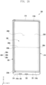
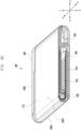
- FIG. 2A is a front perspective view of an electronic device illustrating a first state (e.g., a closed state or a slide-in state) according to an embodiment of the disclosure.
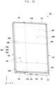
- FIG. 2B is a front perspective view of an electronic device illustrating a second state (e.g., an open state or a slide-out state) according to an embodiment of the disclosure.
- the electronic device 200 illustrated in FIGS. 2A and 2B may be at least partially similar to the electronic device 101 in FIG. 1 , or may further include other embodiments of the electronic device.
- the electronic device 200 may include a first housing 210, a second housing 220, and a flexible display 230.
- the electronic device 200 may be implemented to expand the screen 2301 in a sliding manner.
- the screen 2301 may include an area of the flexible display 230, which is exposed to the outside.
- FIG. 2A shows the electronic device 200 in the state in which the screen 2301 is not expanded
- FIG. 2B shows the electronic device 200 in the state in which the screen 2301 is expanded
- the state in which the screen 2301 is not expanded may be the state in which the second housing 220 does not slide out, and may be referred to as a first state, for example, a closed state, below.
- the state in which the screen 2301 is expanded may be the state in which the screen 2301 is maximally expanded and is no longer expanded by sliding-out of the second housing 220, and may be referred to as a second state, for example, an open state, below.
- sliding-out may indicate that the second housing 220 at least partially moves in a first direction (e.g., a -x axis direction) when the electronic device 200 switches from the closed state to the open state.
- the open state may be defined as the state in which the screen 2301 is expanded compared to the closed state, and provide various sizes of screens 2301 according to the movement position of the second housing 220.
- the state of the electronic device 200 may include a third state, for example, an intermediate state.
- the intermediate state may mean the state between the closed state in FIG. 2A and the open state in FIG. 2B .
- the screen 2301 may include an active area of the flexible display 230, which is visually exposed to output images, and the electronic device 200 may adjust the active area according to a change in the size of the screen 2301 of the flexible display 230 depending on the movement of the second housing 220.
- the open state may indicate the state in which the screen 2301 is maximally expanded.
- the flexible display 230 slidably disposed on the electronic device 200 in FIG. 2A to provide the screen 2301 may be referred to as a "slide-out display", a “stretchable display”, or an “expandable display”.
- the electronic device 200 may include a sliding structure related to the flexible display 230. For example, when the second housing 220 is moved by a configured distance by an external force in order to change the size of the screen 2301 of the flexible display 230, switching from the closed state to the open state or from the open state to the closed state may be performed due to an elastic structure included in the sliding structure (e.g., a semi-automatic sliding operation) even without further external force.
- the electronic device 200 may switch from the closed state to the open state or from the open state to the closed state due to a driving device such as a motor or a hinge connected to the flexible display 230. For example, when a signal is generated through a hardware button or a software button provided through a screen, the electronic device 200 may switch from the closed state to the open state or from the open state to the closed state.
- the electronic device 200 may switch from the closed state to the open state or from the open state to the closed state.
- the electronic device 200 may detect, through a sensor, a squeeze gesture in which a portion (e.g., the palm or finger) of the hand presses a specified section of the electronic device 200, and may switch from the closed state to the open state or from the open state to the closed state in response thereto.
- the flexible display 230 may include a first section 1 (or fixed section) and a second section 2.
- the first section 1 (or fixed section) and the second section 2 may be connected.
- the first section 1 (or fixed section) may be fixed to the first housing 210 and/or at least one support member (e.g., the front case 330 in FIG. 3 ) included inside the first housing 210.
- the second section 2 connected to the first section 1 may slide out due to the movement of the second housing 220, thereby expanding the screen (e.g., see the screen 2301 in FIG. 2B ).
- the flexible display 230 may include the second section (or bendable section) 2 (see FIG. 2B ).
- the second section 2 may include the expanded portion of the screen 2301 when the electronic device 200 switches from the closed state to the open state.
- the second section 2 may slide out of the inner space of the electronic device 200 to be visible to the outside, thereby expanding the screen 2301.
- at least a portion of the second section 2 may slide in the inner space of the electronic device 200, thereby contracting the screen 2301.
- at least a portion e.g., the second section 2 or the bendable section
- the flexible display 230 may be bent.
- the flexible display 230 may include a flexible substrate (e.g., a plastic substrate) that is formed of a polymer material including polyimide (PI) or polyester (PET).
- PI polyimide
- PET polyester
- the second section 2 may at least partially enter the electronic device 200 due to the movement of the second housing 220, thereby contracting the screen (e.g., see the screen 2301 in FIG. 2A ).
- the roller e.g., the roller 400 in FIG. 3 , the roller 400 in FIG. 6 , or the roller 400 in FIG. 7
- the roller may be positioned corresponding to the second section 2, and during the switching between the closed state in FIG. 2A and the open state in FIG. 2B , the roller (e.g., the roller 400 in FIG. 3 , the roller 400 in FIG. 6 , or the roller 400 of FIG. 7 ) may be rotated due to the movement of the second section 2.
- the first housing 210 may include a back cover (not shown), a first side cover 213, or a second side cover 214.
- the back cover (not shown) may form at least a portion of a rear surface (not shown) of the electronic device 200.
- the back cover (not shown) may be substantially opaque.
- the back cover (not shown) may be formed of coated or tinted glass, ceramic, polymer, metal (e.g., aluminum, stainless steel (STS), or magnesium), or a combination of at least two thereof.
- the second section 2 of the flexible display 230 in the state (e.g., the closed state) in which the second section 2 of the flexible display 230 slide in the inner space of the second housing 220, at least a portion of the second section 2 may be disposed so as to be visible to the outside through at least a portion of the back cover (not shown).
- the back cover (not shown) may be formed of a transparent material and/or a translucent material.
- first side cover 213 and the second side cover 214 may be positioned on opposite sides.
- first side cover 213 and the second side cover 214 may be on opposite sides of the flexible display 230 in a second direction (e.g., a y axis direction) perpendicular to the first direction (e.g., the -x axis direction) of the sliding-out of the second housing 220.
- the first side cover 213 may form at least a portion of a first side surface (not shown) of the electronic device 200
- the second side cover 214 may form at least a portion of a second side surface 214a of the electronic device 200, which faces in the opposite direction of the first side surface (not shown).
- the first side cover 213 may include a first edge portion 213b that extends from the edge of the first side surface (not shown).
- the first edge portion 213b may form at least a portion of one side bezel of the electronic device 200.
- the second side cover 214 may include a second edge portion 214b that extends from the edge of the second side surface 214a.
- the second edge portion 214b may form at least a portion of the opposite side bezel of the electronic device 200.
- the surface of the first edge portion 213b, the surface of the second edge portion 214b, and the surface of the second housing 220 may be smoothly connected in the closed state in FIG.
- the surface of the first edge portion 213b or the surface of the second edge portion 214b may include the opposite side curved portion (not shown) corresponding to a second curved portion 230c of the screen 2301, which is positioned opposite the first curved portion 230b.
- At least a portion of the flexible display 230 may be disposed in the second housing 220, and the closed state in FIG. 2A or the open state in FIG. 2B may be determined based on the position of the second housing 220 that moves based on the first housing 210.
- the second housing 220 may include a third side cover 223, a fourth side cover 224, and a third edge portion 220b.
- the third side cover 223 and the fourth side cover 224 may be positioned on opposite sides.
- the third side cover 223 and the fourth side cover 224 may be on opposite sides of the flexible display 230 in the second direction (e.g., the y axis direction) perpendicular to the first direction (e.g., the -x axis direction) of the sliding-out of the second housing 220.
- the third edge portion 220b may form an outer surface of the electronic device 200 (e.g., the surface exposed to the outside to form the exterior of the electronic device 200).
- the third edge portion 220b may form the bezel around the screen 2301 together with the first edge portion 213b and the second edge portion 214b in the closed state in FIG. 2A .
- the third edge portion 220b may extend in the second direction (e.g., the y axis direction) in order to connect one end of the first side cover 213 and one end of the second side cover 214 in the closed state.
- the surface of the third edge portion 220b may be smoothly connected to the surface of the first edge portion 213b and/or the surface of the second edge portion 214b in the closed state in FIG. 2A .
- At least a portion of the second section 2 may slide out of the inside of the electronic device 200 due to the sliding-out of the second housing 220, thereby providing the state (e.g., the open state) in which the screen 2301 is expanded as shown in FIG. 2B .
- the screen 2301 may include a flat portion 230a, and a first curved portion 230b and/or a second curved portion 230c that are positioned on opposite sides of the flat portion 230a.
- the first curved portion 230b and the second curved portion 230c may be substantially symmetrical with respect to the flat portion 230a positioned therebetween.
- the flat portion 230a when the closed state in FIG. 2A is switched to the open state in FIG. 2B , the flat portion 230a may be expanded.
- a partial area of the second section 2, which forms the first curved portion 230b in the closed state in FIG. 2A may be included in the flat portion 230a that expands when switching from the closed state in FIG. 2A to the open state in FIG. 2B .
- the electronic device 200 may include an opening (not shown) of the second section 2 for sliding-in or sliding-out and/or a roller (e.g., the roller 400 in FIG. 3 , the roller 400 in FIG. 6 , or the roller 400 in FIG. 7 ) (or pulley) (not shown) positioned in the opening (not shown).
- the roller e.g., the roller 400 in FIG. 3 , the roller 400 in FIG. 6 , or the roller 400 in FIG. 7
- the roller may be positioned corresponding to the second section 2, and when switching between the closed state in FIG. 2A and the open state in FIG. 2B , movement of the second section 2 and the movement direction thereof may be guided through rotation of the roller (e.g., the roller 400 in FIG.
- the first curved portion 230b may be formed corresponding to the curved surface formed on one surface of the second housing 220.
- the first curved portion 230b may be formed by the portion corresponding to the curved surface of the roller (e.g., the roller 400 in FIG. 3 , the roller 400 in FIG. 6 , or the roller 400 in FIG. 7 ) in the second section 2.
- the electronic device 200 may be implemented as a form in which the flat portion 230a is expanded without the second curved portion 230c.
- the flexible display 230 may further include a touch detection circuit (e.g., a touch sensor).
- a touch detection circuit e.g., a touch sensor
- the flexible display 230 may be combined with or disposed adjacent to a pressure sensor capable of measuring the intensity (pressure) of a touch and/or a digitizer for detecting a pen input device (e.g., a stylus pen) in a magnetic field type.
- the digitizer may include a coil member that is disposed on a dielectric substrate in order to detect a resonance frequency in an electromagnetic induction type, which is applied from a pen input device.
- the electronic device 200 may include a microphone hole 251 (e.g., the input module 150 in FIG. 1 ), a speaker hole 252 (e.g., the sound output module 155 in FIG. 1 ), and/or a connector hole 253 (e.g., the connection terminal 178 in FIG. 1 ).
- the electronic device 200 may exclude at least one of the elements, or may further include other elements.
- the microphone hole 251 may be formed on at least a portion of the second side surface 214a so as to correspond to the microphone (not shown) positioned inside the electronic device 200.
- the position of the microphone hole 251 is not limited to the embodiment in FIG. 2A , and may vary.
- the electronic device 200 may include a plurality of microphones capable of detecting the direction of sound.
- the speaker hole 252 may be formed on at least a portion of the second side surface 214a so as to correspond to a speaker (not shown) positioned inside the electronic device 200.
- the position of the speaker hole 252 is not limited to the embodiment in FIG. 2A , and may vary.
- the electronic device 200 may include call receiver hole.
- the microphone hole 251 and the speaker hole 252 may be implemented as one hole, or the speaker hole 252 may be omitted like a piezo speaker.
- the connector hole 253 may be formed on at least a portion of the second side surface 214a so as to correspond to a connector (e.g., a USB connector) positioned inside the electronic device 200.
- the electronic device 200 may transmit and/or receive power and/or data to and/or from an external electronic device that is electrically connected to the connector through the connector hole 253.
- the position of the connector hole 253 is not limited to the embodiment in FIG. 2A , and may vary.
- the electronic device 200 may include a camera module (e.g., a front camera) that produces an image signal, based on the light received through one surface (e.g., the front surface 200A) of the electronic device 200 that is positioned in the direction in which the screen 2301 faces.
- the camera module e.g., the front camera
- the opening e.g., a through-hole or a notch
- the camera module (e.g., the front camera) (not shown) may receive light through an opening and a portion of a transparent cover that overlaps the opening, thereby producing an image signal.
- the transparent cover may serve to protect the flexible display 230 from the outside, and include a material such as polyimide or ultra-thin glass (UTG).
- the camera module (e.g., the front camera) (not shown) may be disposed at the lower end of at least a portion of the screen 2301 of the flexible display 230, and perform related functions (e.g., an image shooting) while the position of the camera module (e.g., the front camera) (not shown) is not visually distinguished (or exposed).
- the camera module e.g., the front camera
- the camera module may be disposed to overlap at least a portion of the screen 2301 to obtain the image of an external subject without being exposed to the outside.
- the area of the flexible display 230 which faces the camera module, is a portion of the area displaying content, and may be formed as a transmissive area having a specified transmittance.
- the transmissive area may be formed to have a transmittance in the range of about 5% to about 20%.
- the transmissive area may include an area that overlaps the effective area (e.g., the angle-of-view area) of the camera module through which light to be received by an image sensor and produce an image passes.
- the transmissive area of the flexible display 230 may include an area having a lower pixel density and/or wiring density than the surrounding area.
- the transmissive area may replace the opening described above.
- some of the camera modules may include an under display camera (UDC).
- the electronic device 200 may further include a key input device (e.g., the input module 150 in FIG. 1 ).
- the key input device may be positioned on the first side surface (not shown) of the electronic device 200, which is formed by the first side cover 213.
- the key input device may include at least one sensor module.
- the electronic device 200 may include various sensor modules (e.g., the sensor module 176 in FIG. 1 ).
- the sensor module may produce an electrical signal or a data value corresponding to the internal operation state of the electronic device 200 or the external environmental state.
- the sensor module may include a proximity sensor for producing a signal regarding proximity of an external object, based on the light received through the front surface 200A of the electronic device 200, which is disposed in the direction in which the screen 2301 faces.
- the sensor module may include various biometric sensors such as a fingerprint sensor or an HRM sensor for detecting biometric information, based on the light received through the front surface 200A or rear surface (not shown) of the electronic device 200.
- the electronic device 200 may include at least one of various other sensor modules, for example, a gesture sensor, a gyro sensor, an atmospheric pressure sensor, a magnetic sensor, an acceleration sensor, a grip sensor, a color sensor, an infrared (IR) sensor, a biometric sensor, a temperature sensor, a humidity sensor, or an illuminance sensor.
- a gesture sensor for example, a gesture sensor, a gyro sensor, an atmospheric pressure sensor, a magnetic sensor, an acceleration sensor, a grip sensor, a color sensor, an infrared (IR) sensor, a biometric sensor, a temperature sensor, a humidity sensor, or an illuminance sensor.
- a gesture sensor for example, a gesture sensor, a gyro sensor, an atmospheric pressure sensor, a magnetic sensor, an acceleration sensor, a grip sensor, a color sensor, an infrared (IR) sensor, a biometric sensor, a temperature sensor, a humidity sensor, or an illuminance sensor.
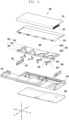
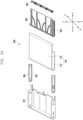
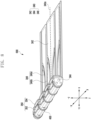
- FIG. 3 is an exploded perspective view of an electronic device according to an embodiment of the disclosure.
- an electronic device 300 may include a flexible display 310 (e.g., the flexible display 230 in FIGS. 2A and 2B ), a bendable member 320 (e.g., a multi-bar assembly), a front case 330, a sliding frame 340, a driving body 350, a guide rail 360, a first housing 380 (e.g., the first housing 210 in FIGS. 2A and 2B ), a second housing 370 (e.g., the second housing 220 in FIGS.
- a flexible display 310 e.g., the flexible display 230 in FIGS. 2A and 2B
- a bendable member 320 e.g., a multi-bar assembly
- a front case 330 e.g., a sliding frame 340
- driving body 350 e.g., a driving body 350
- a guide rail 360 e.g., a first housing 380 (e.g., the first housing 210 in FIGS. 2A and 2B
- the electronic device 300 may have an inner space provided by the front case 330 and the first housing 380, and include a battery (e.g., the battery 188 of FIG. 1 ) and a printed circuit board that are disposed in the inner space.
- a battery e.g., the battery 188 of FIG. 1
- a printed circuit board that are disposed in the inner space.
- At least some of the processor 120, the memory 130, the input module 150, the sound output module 155, the audio module 170, the sensor module 176, the interface 177, and the connection terminal 178, the haptic module 179, the camera module 180, the power management module 188, and the communication module 190, which are shown in FIG. 1 , and/or other components of the electronic device 300 may be disposed in the printed circuit board.
- the flexible display 310 may be formed of a flexible material to be rolled up, and display an image according to an input image signal.
- the flexible display 310 may include a fixed section (e.g., the first section 1 in FIG. 2B ) that is exposed to the outside when the screen (e.g., the screen 2301 in FIGS. 2A and 2B ) is in a contracted state (e.g., the closed state in FIG. 2A ) and a bendable section (e.g., the second section 2 in FIG. 2B ) that is exposed to the outside when the screen 2301 is in an expanded state (e.g., the open state in FIG. 2B ).
- a fixed section e.g., the first section 1 in FIG. 2B
- a contracted state e.g., the closed state in FIG. 2A
- a bendable section e.g., the second section 2 in FIG. 2B
- the bendable member 320 may include a plurality of guide bars (e.g., the plurality of guide bars 322 in FIG. 5B ) that are rotatably combined with each other to enable the rolling operation of the flexible display 310.
- the bendable member 320 may be attached to at least a portion of the rear surface of the flexible display 310 using an adhesive (e.g., a thermally reactive adhesive member, a photoreactive adhesive member, a general adhesive, and/or a double-sided tape), and the plurality of guide bars (e.g., the plurality of guide bars 322 in FIG. 5B ) of the bendable member 320 may be disposed to have a predetermined gap therebetween.
- an adhesive e.g., a thermally reactive adhesive member, a photoreactive adhesive member, a general adhesive, and/or a double-sided tape
- the bendable member 320 may support the bendable section (e.g., the bendable section 2 in FIG. 2B ) such that the bendable section (e.g., the bendable section 2 in FIG. 2B ) of the flexible display 310 may be maintained to be smoothly connected with the fixed section (e.g., the fixed section 1 of FIG. 2B ) of the flexible display 310.
- the electronic device 300 may further include a support plate (not shown) that is connected to the bendable member 320.
- the support plate (not shown) may be connected to guide bar that is disposed in the outermost end of the plurality of guide bars (e.g., the plurality of guide bars 322 in FIG. 5B ) in order to support the fixed section (e.g., the fixed section 1 in FIG. 2B ).
- the front case 330 may support at least a portion of the flexible display 310 through an upper surface thereof, and provide a space in order for the electronic components such as a battery (e.g., the battery 188 in FIG. 1 ) or a printed circuit board to be disposed.
- a battery e.g., the battery 188 in FIG. 1
- a printed circuit board e.g., a printed circuit board
- the sliding frame 340 may include a slide plate 342 and a sliding bar 344.
- the sliding frame 340 may be integrally formed with the sliding bar 344.
- the sliding frame 340 may be formed to be separate from the sliding bar 344, and may be structurally coupled thereto.
- a plurality of guide slits 346 may be included in the slide plate 342. Some guide slits 346b among the plurality of guide slits 346 may be formed by cutting a portion of the slide plate 342 to have a predetermined width, and the remaining guide slits 346a may be formed such that a portion of the driving body 350 is inserted thereto to be guided.
- the plurality of guide slits 346 may include a plurality of first guide slits 346a having a predetermined curvature and a plurality of second guide slits 346b having a linear shape.
- a driving shaft (e.g., the driving shaft 356 in FIG. 9 ) of the driving body 350 may be inserted into the plurality of first guide slits 346a.
- the driving shaft 356 may move along the curve formed to have a curvature in the plurality of the first guide slits 346a according to folding and unfolding of the driving body 350.
- a first link portion e.g., the first link portion 352a in FIG.
- a second link portion (e.g., the second link portion 354a in FIG. 12A ) of the driving body 350 may be at least partially inserted into the plurality of the second guide slits 356b.
- the first link portion 352 and the second link portion 354 may move along the second guide slit 346b according to folding or unfolding of the driving body 350.
- the sliding frame 340 may slide in the x axis direction and the -x axis direction according to movement of the driving body 350 and/or the second housing 370, and expand or contract a screen (e.g., the screen 2301 in FIG. 2B ) of the flexible display 310.
- the sliding frame 340 may push the bendable member 320 in the -x axis direction to expand the screen (e.g., the screen 2301 in FIG. 2B ) of the flexible display 310.
- the expanded state e.g., the open state
- the screen e.g., the screen 2301 in FIG.
- the sliding frame 340 may push the bendable member 320 in the x axis direction to contract the screen (e.g., the screen 2301 in FIG. 2B ) of the flexible display 310.
- the sliding frame 340 may support at least a portion of the bendable member 320 in a curved portion 300d (e.g., the first curved portion 230b in FIGS. 2A and 2B or the curved portion 300d in FIG. 4D ).
- the sliding frame 340 may support the bendable member 320 in a flat area (e.g., the flat area in FIGS. 2A and 2B ) other than the curved portion 300d.
- the roller 400 may be inserted into a roller hole (e.g., the roller hole 348 in FIG. 6 ) that is formed at regular intervals in the sliding bar 344.
- the roller 400 may be self-rotatably coupled to the roller hole. Accordingly, when the sliding frame 340 moves from the closed state to the open state or from the open state to the closed state, the contact-frictional force between the bendable member 340 and the slide bar 344 may be reduced through the rotatable roller 400 in contact with at least a portion of the bendable member 340.
- the driving body 350 includes a first driving bar 352, a second driving bar 354, a driving shaft 356, and an elastic member (e.g., the elastic member 358 in FIGS. 12A and 12B ).
- the first driving bar 352 and the second driving bar 354 may be coupled by the driving shaft 356, and the first driving bar 352 and the second driving bar 354 may pivot to each other with respect to the driving shaft 356.
- the elastic member e.g., the elastic member 358 in FIGS. 12A and 12B
- the first driving bar 352 and the second driving bar 354 may be unfolded by a specified angle by the elastic member (e.g., the elastic member 358 in FIGS. 12A and 12B ) in the case where no external force is applied.
- the elastic member e.g., the elastic member 358 in FIGS. 12A and 12B
- the first driving bar 352 and the second driving bar 354 may have an angle limit structure that prevents the first driving bar 352 and the second driving bar 354 from being unfolded at a specified angle or more through the elastic member (e.g., the elastic member 358 in FIGS. 12A and 12B ).
- the angle limit structure may include a locking protrusion and a locking portion that are formed on the first driving bar 352 and the second driving bar 354.
- the driving body 350 may be disposed such that the first driving bar 352 is rotatably coupled to the sliding frame 340 and such that the second driving bar 354 is rotatably coupled to the front case 330.
- the disclosure is not limited thereto, and the first driving bar 352 of the driving body 350 may be coupled to the front case 330, and the second driving bar 354 may be coupled to the sliding frame 340.
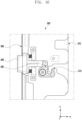
- the electronic device 300 may include a locking device (e.g., the locking device 382 in FIGS. 15 and 16 ) that is disposed on the rear surface (e.g., the surface opposite the surface on which the flexible display 310 is disposed) of the first housing 380, and a locking jaw (e.g., the locking jaw 372 in FIGS. 16 and 17 ) that is formed on the rear surface (e.g., the surface opposite the surface on which the flexible display 310 is disposed) of the second housing 370.
- a locking device e.g., the locking device 382 in FIGS. 15 and 16
- a locking jaw e.g., the locking jaw 372 in FIGS. 16 and 17
- the first driving bar 352 and the second driving bar 354 may remain in the folded state through the locking structure in which the locking device is engaged with the locking jaw (e.g., the locking jaw 372 in FIGS. 16 and 17 ).
- the first driving bar 352 and the second driving bar 354 may be coupled by the driving shaft 356, and the first driving bar 352 and the second driving bar 354 may be folded or unfolded around the driving shaft 356.
- the guide rail 360 may include a guide groove 362 (e.g., the guide groove 362 in FIG. 5A ) on which at least a portion (e.g., the protrusion 324 in FIG. 5B ) of the flexible display 310 and/or the bendable member 320 is supported.
- the guide rail 360 may provide a path through which the flexible display 310 and/or the bendable member 320 moves through the guide groove 362.
- it may be disposed inside the guide rail 360 in the y axis direction and the -y axis direction, respectively.
- the guide groove 362 may be formed to have a length in the x axis direction and the -x axis direction in the guide rail 360.
- the guide rail 360 may have a shape corresponding to the shape of a third side cover (e.g., the third side cover 223 in FIGS. 2A and 2B ) and/or a fourth side cover 224. Accordingly, the bendable section (e.g., the bendable section 2 in FIG. 2B ) of the flexible display 310 may slide in the second housing 370 (e.g., move in the x axis direction) or slide out of the same (e.g., move in the -x axis direction) along the guideline 360 so that the flexible display 310 may slide in or slide out while being seamlessly connected to the side surface (e.g., the third edge portion 220b in FIGS. 2A and 2B ) of the second housing 370.
- the side surface e.g., the third edge portion 220b in FIGS. 2A and 2B
- the second housing 370 may move together with the flexible display 310, thereby forming the exterior of the electronic device 300.
- the first housing 380 may be coupled to the front case 330, provide a space for the electronic components (e.g., the printed circuit board, the battery, the sensor module, the sound module, or the camera module) disposed inside the electronic device 300, and form at least a portion of the exterior of the electronic device 300.
- the electronic components e.g., the printed circuit board, the battery, the sensor module, the sound module, or the camera module
- the back cover 390 (e.g., back glass) may be coupled to at least a portion of the first housing 380, and may be the external case of the electronic device 300.
- the back cover 390 may be formed of polymer, coated or tinted glass, ceramic, metal (e.g., aluminum, stainless steel (STS), or magnesium), or a combination of at least two thereof.
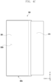
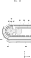
- FIG. 4A is a view illustrating a front surface (e.g., a surface on which a screen is displayed) of an electronic device 300 in a first state (e.g., a closed state) according to an embodiment of the disclosure.
- FIG. 4B is a view illustrating a front surface (e.g., a surface on which a screen is displayed) of an electronic device 300 in a second state according to an embodiment of the disclosure.
- FIG. 4C is a view illustrating a rear surface of an electronic device 300 in a first state according to an embodiment of the disclosure.
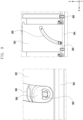
- FIG. 4D is a cross-sectional view of an electronic device according to an embodiment of the disclosure.
- FIG. 5A is a view illustrating the configuration of a sliding module 500 of an electronic device 300 according to an embodiment of the disclosure.
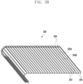
- FIG. 5B is a view illustrating a bendable member of an electronic device according to an embodiment of the disclosure.
- the electronic device 300 in FIGS. 4A to 4D may be at least partially similar to the electronic device 101 in FIG. 1 or the electronic device 200 in FIGS. 2A and 2B , or may further include other embodiments of the electronic device.
- FIG. 4D is a cross-sectional perspective view of the electronic device 300 taken along the line A1-A2 in FIG. 4A .
- a slide module 500 of the electronic device 300 may include a bendable member 320 supporting at least a portion of a flexible display 310 (e.g., the flexible display 230 in FIG. 2A ), a sliding frame 340 (e.g., the first housing), a driving body 350, a guide rail 360, and a second housing 370.
- a screen e.g., the screen 2301 in FIGS. 2A and 2B ) of the flexible display 310 may be expanded and contracted by the slide module 500.
- the bendable member 320 may include a plurality of guide bars 322 rotatably connected to each other.
- the bendable member 320 may include an upper surface 320a formed through a plurality of guide bars 322 and a rear surface 320b (e.g., a rear surface) facing in the direction opposite the upper surface 320a (e.g., a front surface).
- the upper surface 320a may face the flexible display 310
- the rear surface 320b may face the inner space of the electronic device 200 (e.g., the second housing 220).
- the plurality of guide bars 322 may be formed of a metal material and/or polymer.
- Each of the plurality of guide bars 322 may include the guide protrusions 324 that protruding from both ends thereof to be guided along the guide rail 360 in the inner space of the electronic device 300.
- some or all of the plurality of guide bars 322 may include a friction reducing area (e.g., at least one of a polyoxymethylene (POM) layer, an acetal layer, or a Teflon layer) to reduce friction.
- the friction reducing area may be included in the area in which contact (or friction) of at least one guide bar among the plurality of guide bars 322 occurs.
- the friction reducing area may be included as a layer (e.g., a coating layer) in the area in contact with at least a portion of the slide plate 342, the sliding bar 344, the roller 400, and/or the driving body 350. Accordingly, frictional resistance with a corresponding structure (e.g., the slide plate 342, the sliding bar 344, the roller 400, and/or the driving body 350) according to the sliding operation of the bendable member 320 may be reduced.
- the sliding frame 340 may be coupled to the second housing 370 that moves a specified reciprocating distance from the first housing 380 (or the front case 330). At least a portion of the flexible display 310 may be attached to the bendable member 320 and may be supported by at least a portion of the bendable member 320. The bendable member 370 may be supported by the front case 330 and/or the sliding frame 340.
- one area (e.g., the area corresponding to the first housing 380 or the fixed area 314) of the bendable member 320 may be supported by the front case 330.
- another area e.g., the area corresponding to the second housing 370 or the extension area 312
- the fixed area 314 of the flexible display 310 supported by the bendable member 320 may form a flat surface by the front surface (e.g., the surface facing the flexible display 310) of the front case 330.
- a portion of the extension area 312 of the flexible display 310 may form a flat surface by the flat area (e.g., the slide plate 342 in FIG. 3 ) of the sliding frame 340, and another portion may form a curved surface by the curved area (e.g., the sliding bar 344 in FIG. 3 ) of the sliding frame 340.
- the bendable member 320 may be accommodated in the second housing 370.
- the bendable member 320 may slide in the space between the sliding frame 340 and the second housing 370 while being supported by the sliding bar (e.g., the sliding bar 344 in FIG. 3 ) of the electronic device 300.
- the sliding bar e.g., the sliding bar 344 in FIG. 3
- at least a partial area of the bendable member 320 may come into contact with the driving body 350.
- the bendable member 320 when switching from the open state to the closed state or switching from the closed state to the open state, may have friction with the slide plate 342, the sliding bar 344, and/or the driving body 350 due to contact with at least a portion thereof.
- the electronic device 300 may reduce friction due to contact with at least a portion of the slide plate 342, the sliding bar 344, and/or the driving body 350.
- the area of the bendable member 320 substantially corresponding to the fixed area 314 may be formed of a plate (e.g., a support plate). At least a portion (e.g., the bendable section 2 in FIG. 2B ) of the flexible display 310 may be accommodated in the inner space of the second housing 370 while being supported by the bendable member 320 (or by the bendable member 320) in the closed state to then be disposed to be invisible to the outside.
- a plate e.g., a support plate.
- At least a portion (e.g., the bendable section 2) of the flexible display 310 may be disposed to be visible to the outside while being supported by the bendable member 320 in the open state.
- the areas of the front surface 300a and the rear surface 300b of the electronic device 300 may vary depending on the state of the electronic device 300 (e.g., the open state or the closed state). For example, when the electronic device 300 is in the open state (e.g., the open state in FIG. 2B ), the bendable section 2 of the flexible display 310 may slide out so that the area of the front surface 300a of the electronic device 300 may increase. For example, when the electronic device 300 is in the closed state (e.g., the closed state in FIG. 2A ), the area of the rear surface of the electronic device 300 may include the area of the rear cover 390. In addition, when the electronic device 300 is in the open state, the area of the rear surface of the electronic device 300 may include the area substantially corresponding to the bendable area 2 among the area of the rear cover 390 and the rear surface of the second housing 370.
- the open state e.g., the open state in FIG. 2B
- the bendable section 2 of the flexible display 310 may slide out so that the area of
- the flexible display 310 may include a fixed area 314 (e.g., the fixed section 1 in FIG. 2B ) always visible to the outside and an extension area 312 (e.g., the bendable section 2 in FIG. 2B ) that extends from the fixed area 314 and slides in the second housing 370 or slides out of the same according to movement of second housing 370.
- a fixed area 314 e.g., the fixed section 1 in FIG. 2B
- an extension area 312 e.g., the bendable section 2 in FIG. 2B
- the extension area 312 (e.g., the second area) (e.g., the bendable section 2 in FIG. 2B ) of the flexible display 310 may be extended along the first direction (e.g., the -x axis direction) while being supported by the bendable member 320 in the open state.
- the fixed area 314 e.g., the first area
- the extension area 312 e.g., the second area
- the bendable section 2 in FIG. 2B may form substantially the same plane.
- the size (or area) of the display area (e.g., the screen 2301 in FIGS. 2A and 2B ) of the flexible display 310 may vary.
- an operation of expanding the screen (e.g., sliding-out) and/or contracting the screen (e.g., sliding-in) of the electronic device 300 may be manually performed through a user's manipulation.
- an operation of expanding the screen (e.g., sliding-out) and/or contracting the screen (e.g., sliding-in) of the electronic device 300 may be performed automatically or semi-automatically using a driving device (e.g., a motor, a ball screw, a cam, a slider crank, or a hinge).
- a driving device e.g., a motor, a ball screw, a cam, a slider crank, or a hinge.
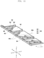
- FIG. 6 is a view illustrating a sliding frame module 600 of an electronic device according to an embodiment of the disclosure.
- FIGS. 7 and 8 are views showing that a driving body 350 is coupled to a sliding frame 340 and that a roller 400 is coupled to a sliding bar 344 according to various embodiments of the disclosure.
- a sliding frame module 600 may include a sliding frame 340, a driving body 350, and a roller 400.
- a first driving bar 352 (e.g., the first driving bar 352 in FIG. 11 ) may be self-rotatably coupled to the sliding frame 340 (e.g., the second housing), and a second driving bar 354 (e.g., the second driving bar 354 in FIG. 11 ) may be self-rotatably coupled to the front case 330 (e.g., the first housing) so that the driving body 350 may be folded or unfolded.
- the first driving bar 352 and the second driving bar 354 may be pivotally connected by a driving shaft 356.
- the driving body 350 may be folded about the driving shaft 356 such that the first driving bar 352 and the driving bar 354 come into contact with each other or are unfolded to open at a specified angle.
- the first driving bar 352 and the second driving bar 354 may have the same shape or different shapes from each other, and it should be noted that the driving bar coupled to the sliding frame 340 will be referred to as a first driving bar 352 and that the driving bar coupled to the front case 330 will be referred to as a second driving bar 354 below, regardless of the disposed direction and shape of the driving body 350.
- a plurality of guide slits 346 may include a plurality of first guide slits 346a having a predetermined curvature and a plurality of second guide slits 346b having a linear shape.
- the plurality of first guide slits 346a and the plurality of second guide slits 346b may be alternately disposed.
- the plurality of first guide slits 346a and the plurality of second guide slits 346b may be irregularly disposed.
- the plurality of first guide slits 346a may have the same shape or different shapes from each other.
- the plurality of first guide slits 346a may be formed to have the same shape, for example, to have a curve having the same direction and circumferential angle, but in this case, pressure may be applied to the sliding frame 340 in one direction, thereby causing distortion or deformation of the sliding frame 340.
- the plurality of first guide slits 346a may be formed to be symmetrical with each other, based on the center line 340a (e.g., the center line 340a in FIG. 11 ) of the sliding frame 340.
- At least one first guide slit 346a formed on a first side (e.g., the y axis direction) of the center line 340a and at least one first guide slit 346a formed on a second side thereof (e.g., the -y axis direction) may be disposed.
- At least one first guide slit 346a formed on the first side (e.g., the y axis direction) and at least one first guide slit 346a formed on the second side (e.g., the -y axis direction) may be formed to have a shape symmetrical with each other based on the center line 340a.
- At least one first guide slit 346a formed on the first side of the center line 340a may be formed to have a predetermined curvature in a first direction
- at least one first guide slit 346a formed on the second side thereof may be formed to have a predetermined curvature in a second direction opposite the first direction.
- the plurality of first guide slits 346a may include the same number of at least one first guide slit 356a on both sides of the center line 340a.
- the plurality of second guide slits 346b may have a linear shape. Each of the second guide slits 356b may form an opening directed to the front case 330 on the slide plate 342. A first link portion 352a and a second link portion 354a of the driving body 350 may be disposed in the second guide slit 356b to move linearly, and the second link portion 354a may be coupled to the front case 330 through the opening.
- the plurality of second guide slits 356b may include the same number of at least one second guide slit 356b on both sides of the center line 340a.
- the plurality of driving bodies 350 may be disposed in the same direction, but in this case, distortion and/or deformation of the sliding frame 340 may occur as described above. To prevent this, the plurality of driving bodies 350 may be disposed to be symmetrical with each other based on the center line 340a of the sliding frame 340 (e.g., the center line 340a in FIG. 11 ). For example, the driving bodies 350 on the first side of the center line 340a and the driving bodies 350 on the second side thereof may be disposed to be folded or unfolded in a symmetrical form.
- a plurality of roller holes 348 may be formed at regular intervals in the sliding bar 344.
- the roller hole 348 may have a predetermined width in order for the roller 400 to be inserted thereinto.
- Rollers 400 corresponding to the number of roller holes 348 may be coupled to the sliding bar 344.
- a corresponding number of rollers 400 may be disposed on both sides of the center line 340a.
- one roller 400 corresponding to the position of the center line 340a may be located at the center of the sliding bar 344, and an equal number of remaining rollers 400 may be located on both sides of the center line 340a.
- the roller 400 may have a shape corresponding to the shape of the roller hole 348.
- the width of the roller 400 may correspond to the width of the roller hole 348, or may be smaller than the width of the roller hole 348 by a predetermined value (e.g., 0.5mm).
- the roller 400 may have a diameter corresponding to the sliding bar 344.
- the roller 400 when the roller 400 is coupled to the sliding bar 344 through the roller hole 348, the roller 400 may not substantially protrude or be recessed.
- at least a portion (e.g., 0.1 to 0.2mm) of the roller 400 may protrude.
- the bendable member 320 when the bendable member 320 moves on the sliding bar 344, the bendable member may come into contact with the sliding bar 344 and the roller 400, thereby producing frictional resistance. This frictional resistance may be reduced by the rotational force of the roller.
- the bendable member 320 in the case where a relatively large number of rollers 400 are rotatably disposed in the sliding bar 344 and protrude above the outer surface of the sliding bar 344, the bendable member 320 may come into contact with only a plurality of rollers 400, which may further reduce the frictional resistance.
- the roller 400 may have only a single roller that has a length similar to that of the sliding bar 344 and is rotatably fixed to the sliding bar.
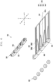
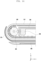
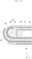
- FIG. 9 is a view illustrating a first guide slit 346a formed in a sliding frame and a driving body 350 coupled to the first guide slit 346a according to an embodiment of the disclosure.
- FIGS. 10A and 10B are views showing that a roller 400 is coupled to a sliding bar 344 according to various embodiments of the disclosure.
- driving shafts 356 of a plurality of driving bodies 350 may be inserted and coupled to a plurality of first guide slits 346a of the sliding frame 340.
- the driving body 350 may include a link 355 for convenience of assembly when a driving shaft 356 is inserted into the first guide slit 346a.
- the driving shaft 356 is coupled to the first guide slit 346a, at least a portion of the driving shaft 356 may move along the first guide slit 346a.
- a first driving bar e.g., the first driving bar 352 in FIGS. 11 and 12A
- a second driving bar e.g., the second driving bar 354 in FIGS.
- a first link portion 352a and a second link portion 354b may reciprocate in the second guide slit 346b to move away from or close to each other. Accordingly, the driving shaft 356 may move in a curve along the first guide slit 346a according to the positions of the first link portion 352a and the second link portion 354a.
- a plurality of roller holes 348 may be formed at regular intervals in the sliding bar 344.
- the roller hole 348 may be formed to have a predetermined width in order for the roller 400 to be inserted thereinto.
- the roller 400 may include a roller body 402 and a roller shaft 404.
- a through-hole 406 passing through the roller body may be formed in the center of the roller body 402, and the roller shaft 404 may be fitted into the through-hole 406 so that the roller body 402 may rotate.
- the roller 400 may be formed by injecting the roller body 402 and the roller shaft 404 into a single component.
- the roller 400 may be fitted into each roller hole 348, and the roller shaft 404 may be fitted into a roller shaft hole 348a formed in the sliding bar 344 so that the roller 400 may be rotatably mounted or coupled to the sliding bar 344.
- the roller body 402 may protrude above the sliding bar 344 such that the bendable member 320 and the roller body 402 come into contact with each other, so that the bendable member 320 may move by the rotation of the roller 400, thereby reducing frictional resistance produced in the bendable member 320.
- rotational movement of the roller 400 may reduce the friction between the bendable member 320 and the sliding bar 344.
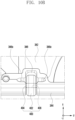
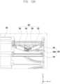
- FIG. 11 is a view showing that a driving body 350 coupled to a sliding frame 340 is unfolded to move the sliding frame 340 according to an embodiment of the disclosure.
- a plurality of driving bodies 350 operates to be unfolded (e.g., sliding-out) (e.g., open state driving), thereby pushing the sliding bar 344 in a first direction (e.g., the -x axis direction) to guide the sliding frame 340 in the slide-out direction (e.g., the -x axis direction).
- the second housing 370 to which the sliding frame 340 is coupled may move in the first direction (e.g., the -x axis direction) together with the sliding frame 340, and an extension area (e.g., the extension area 312 in FIG. 5A ) of the flexible display 310 may slide out of the second housing 370 to be visible to the outside.
- the driving body 350 operates to be folded (e.g., sliding-in) (e.g., closed state driving), thereby moving the sliding bar 344 in a second direction (e.g., the x axis direction) opposite the first direction (e.g., -x axis direction) to guide the sliding frame 340 in the slide-in direction.
- the second housing 370 coupled to the sliding frame 340 may move together with the sliding frame 340, and the extension area (e.g., the extension area 312 in FIG. 5A ) of the flexible display 310 may slide in the second housing 370 to be invisible to the outside.
- the electronic device 300 may switch from the closed state to the open state or from the open state to the closed state by automatically or semi-automatically pushing or pulling the sliding bar 344 using a driving force of the motor.
- the plurality of driving bodies 350 may prevent the flexible display 310 from sagging by supporting the bendable member 320 during operation.
- the sliding bar 344 of the sliding frame 340 may come into contact with a bent portion of the bendable member 320 in a curved portion (e.g., the curved portion 300d in FIG. 4D ). For example, when the bendable member 320 moves, friction may occur between the guide bars 322 in contact with the curved portion of the sliding bar 344, among the plurality of guide bars 322 included in the bendable member 320, and the bendable member 320.
- the sliding bar 344 may be formed of a metal material and/or polymer.
- the sliding bar 344 may be formed of a material that reduces friction, or may further include a layer (e.g., a Teflon-coated layer or a hard coated layer) for reducing friction.
- the layer for reducing friction may be disposed on the surface in contact with the sliding bar 344 of the bendable member 320.
- FIG. 12A is a diagram illustrating a driving body 350 of an electronic device according to an embodiment of the disclosure.
- FIGS. 12B to 12F are views illustrating a coupling structure between a sliding frame 340 and a driving body 350 and a coupling structure between a driving body 350 and a front case 330 according to various embodiments of the disclosure.
- the driving body 350 may include a first driving bar 352 rotatably coupled to the sliding frame 340, a second driving bar 354 rotatably coupled to the front case 330, and an elastic member 358 for pressing the first driving bar 352 and the second driving bar 354 in the direction in which they are unfolded.
- the first driving bar 352 and the second driving bar 354 may be rotatably coupled through a driving shaft 356.
- the driving body 350 and the sliding bar 344 may be rotatably coupled through a first coupling pin 357.
- the driving body 350 and the front case 330 may be rotatably coupled through a second coupling pin 359.
- the first driving bar 352 and the driving shaft 356 may be integrally formed.
- the second driving bar 354 and the driving shaft 356 may be integrally formed.
- the driving shaft 356 may be formed as a separate configuration from the first driving bar 352 and the second driving bar 354.
- the first driving bar 352 and the second driving bar 354 may be unfolded at a predetermined angle (e.g., the angle ⁇ in FIG. 12A ).
- the sliding bar 344 may extend from the front case 330 in the first direction (e.g., the -X axis direction).
- the first driving bar 352 and the second driving bar 354 may be disposed to be adjacent to or come into at least partial contact with the sliding bar 344 of the sliding frame 340.
- the sliding bar 344 may move in the second direction (e.g., the X axis direction) to be disposed adjacent to the front case 330.
- the driving body 350 may be formed to have a predetermined length, and a first link portion 352a for a connection with the sliding bar 344 may be formed at the end of the first driving bar 352, and a second link portion 354a for a connection with the front case 330 may be formed at the end of the second driving bar 354.
- a first coupling pin 357 may be inserted into the first link portion 352a of the first driving bar 352 and the sliding bar 344 so that the first driving bar 352 may be rotatably coupled to the sliding bar 344.
- a second coupling pin 359 may be inserted into the second link portion 354a of the second driving bar 354 and the front case 330 so that the second driving bar 354 may be rotatably coupled to the front case 330.
- the predetermined angle ⁇ may be determined within a range of less than 180 degrees in order to induce an effective folding operation of the first driving bar 352 and the second driving bar 354.
- the first driving bar 352 and the second driving bar 354 may be formed of a metal material and/or polymer.
- the first driving bar 352 and/or the second driving bar 354 may include a friction reducing member or a friction reducing layer disposed on the portion in contact with the bendable member 320.
- the elastic member 358 may be a torsion spring, and may be received inside a first spring receiving groove 352b formed in the first driving bar 352 and a second spring receiving groove 354b formed in the second driving bar 354.
- the elastic member 358 may be disposed so as not to protrude to the outside, and may provide an elastic force such that the first driving bar 352 and the second driving bar 354 may be unfolded.
- FIG. 13 is a view illustrating the state in which a roller 400 is disposed in an electronic device 300 according to an embodiment of the disclosure.
- FIG. 14 shows that friction is reduced by a roller 400 when the electronic device 300 is in a closed state (e.g., a first state) (e.g., a screen contraction state) (e.g., rolling-in or sliding-in) and an open state (e.g., a second state) (e.g., a screen expansion state) (e.g., rolling-out or sliding-out) according to an embodiment of the disclosure.
- a closed state e.g., a first state
- a screen contraction state e.g., rolling-in or sliding-in
- an open state e.g., a second state
- a screen expansion state e.g., rolling-out or sliding-out
- friction may occur in the bendable member 320 supporting the flexible display 310.
- a screen e.g., the screen 2301 in FIGS. 2A and 2B
- friction may occur between the bendable member 320 and the slide plate 342, between the bendable member 320 and the sliding bar 344, and/or between the bendable member 320 and the driving body 350.
- at least a portion of the bendable member 320, the slide plate 342, the sliding bar 344, and/or the driving body 350 may use a friction reducing material or include a friction reducing layer.
- a component for reducing friction e.g., the roller 400
- a friction reducing member may be further disposed.
- FIGS. 15 and 16 are views showing that a closed state (e.g., a first state) is maintained by a locking device according to various embodiments of the disclosure.
- FIG. 17 is a view showing switching to an open state (e.g., a second state) by releasing a locking device according to an embodiment of the disclosure.
- the electronic device 300 may include a locking device 382 and a locking jaw 372 that prevents the driving body (e.g., the driving body 350 in FIG. 3 ) from being unfolded by an elastic body (e.g., the elastic member 358 in FIG. 12A ) and maintains the electronic device 300 in the closed state.
- a locking device 382 and a locking jaw 372 that prevents the driving body (e.g., the driving body 350 in FIG. 3 ) from being unfolded by an elastic body (e.g., the elastic member 358 in FIG. 12A ) and maintains the electronic device 300 in the closed state.
- the locking device 382 may be disposed on the rear surface (e.g., the surface opposite the surface on which the flexible display 310 is disposed) of the first housing 380 in order to provide a fastening force (or fixing force) against the elastic force of the elastic member 358.
- the locking jaw 372 may be formed on the rear surface of the second housing 370 so as to be caught on the locking device 382. When the locking device 382 is caught on the locking jaw 372, switching of the state by the elastic force of the elastic member (e.g., the elastic member 358 in FIGS. 12A and 12B ) may be suppressed.
- the locking device 382 may be caught on the locking jaw 372 to provide a fastening force (or fixing force) against the elastic force of the elastic member (e.g., the elastic member 358 in FIGS. 12A and 12B ), thereby maintaining the electronic device 300 in the closed state.
- the first driving bar 352 and the second driving bar 354 of the driving body e.g., the driving body 350 in FIGS. 12A and 12B
- the driving body may remain in the folded state.
- the first driving bar 352 and the second driving bar 354 of the driving body 350 may be unfolded at a predetermined angle by the elastic force of the elastic member (e.g., the elastic member 358 in FIGS. 12A and 12B ).
- the electronic device 300 may consistently remain in the open state (e.g., the second state) by the elastic force of the elastic member (e.g., the elastic member 358 in FIGS. 12A and 12B ).
- the electronic device 300 may include an open button 384 connected to the locking device 382.
- the locking device 382 may be released from the locking jaw 372 so that the electronic device 300 may switch to the open state by the elastic force provided by the elastic member 358.
- the electronic device 300 may switch to the open state automatically or semi-automatically through a driving mechanism (e.g., a driving motor, a reducer module, and/or a gear assembly) disposed inside the electronic device 300.
- a driving mechanism e.g., a driving motor, a reducer module, and/or a gear assembly
- the electronic device 300 may switch the state manually by a force to push or pull the housing, which is provided by the user, and the method of opening/closing the electronic device 300 is not limited.
- the electronic device 300 may detect, through a processor (e.g., the processor 120 in FIG. 1 ), an event informing of switching to the closed state (e.g., the first state) or the open state (e.g., the second state) of the electronic device 300.
- the processor 120 may detect the open state (e.g., the second state) or the closed state (e.g., the first state) of the electronic device 300 through at least one sensor (e.g., a hall sensor) included in the first housing 380 or the second housing 370 of the electronic device 300.
- the electronic device 300 may adjust the image to be displayed on the flexible display 310 to fit the screen size.
- FIG. 18 is a view illustrating a roller 400 and a bendable member 320 according to an embodiment of the disclosure.
- the roller 400 of the electronic device 300 may include a roller body (e.g., the body 402 in FIG. 10B ) and a roller shaft (e.g., the roller shaft 404 in FIG. 10B ).
- the roller body (e.g., the body 420 in FIG. 10B ) of the roller 400 may be formed of a material that produces low resistance or frictional force when rubbing against other objects.
- the material may be formed of, but not limited to, one of rubber, a urethane material, or Teflon.
- a material providing a smooth surface or having elasticity may be included.
- the roller body (e.g., the body 420 in FIG. 10B ) of the roller 400 may be formed of general PC injection or a metal material.
- FIG. 19 is a view illustrating a roller 400 and a bendable member 320 according to an embodiment of the disclosure.
- the roller 400 may include a roller body 405 of a metal material, a friction reducing member 407 disposed to surround the outer surface of the roller body 405, and a roller shaft 404.
- the roller body 405 may be formed of a metal material.
- the friction reducing member 407 may be formed of a low friction rubber or Teflon tape.
- FIG. 20 is a view illustrating the shape of a sliding bar according to an embodiment of the disclosure.
- the roller 400 may be formed to have a relatively small size (e.g., a diameter) through a protrusion 349 of a sliding bar 344 that extends near the roller 400 and is disposed to at least partially surround the roller 400, so the small size may enable other components of the electronic device 300 to be disposed in a provided space.
- a relatively small size e.g., a diameter
- FIG. 21 is a view illustrating a buffer member 700 disposed between a roller 400 and a bendable member 320 according to an embodiment of the disclosure.
- a buffer member 700 may be disposed between the roller 400 and the bendable member 320 to reduce friction between the roller 400 and the bendable member 320.
- the buffer member 700 may be in the form of a thin film capable of being inserted between the roller 400 and the bendable member 320, and may be formed of a rubber material or a Teflon tape. Since the roller 400 and the bendable member 320 do not come into direct contact with each other by the buffer member 700, frictional resistance may be reduced.
- FIG. 22 is a view showing that a bearing 800 is applied to a sliding bar 344 according to an embodiment of the disclosure.
- a plurality of bearings 800 may be disposed on the outer side of the sliding bar 344 in order to reduce friction produced when the sliding bar 344 and the bendable member 320 come into contact with each other.
- the frictional force produced when the sliding bar 344 and the bendable member 320 come into contact with each other may be reduced by the plurality of bearings 800, and the plurality of bearings 800 may be separated from the sliding bar 344.
- a buffer member 900 may be disposed to cover the plurality of bearings 800.
- a plurality of bearings 800 may be disposed on the sliding bar 344.
- the plurality of bearings 800 may be disposed at regular intervals from the lower portion to the upper portion of the sliding bar 344 to correspond to the entire area in which the sliding bar 344 and the bendable member 320 come into contact with each other. Accordingly, friction during the movement of the sliding frame 340 may be reduced by the plurality of bearings 800 disposed at regular intervals on the sliding bar 344.
- the buffer member 900 may be disposed between the sliding bar 344 and the bendable member 320.
- the buffer member 900 may be in the form of a thin film capable of being inserted between the sliding bar 344 and the bendable member 320, and may be formed of a rubber material or a Teflon tape.
- the sliding bar 344 and the bendable member 320 do not come into direct contact with each other by the buffer member 900, thereby reducing friction.
- friction produced when the sliding bar 344 and the bendable member 320 come into contact with each other may be reduced by the buffer member 900.
- FIG. 23 is a view showing that a friction reducing member 1000 is applied to reduce friction between a driving shaft 356 and a sliding frame 340 according to an embodiment of the disclosure.
- the driving shaft 356 of the driving body 350 may be inserted into the first guide slit 346a of the sliding frame 340 to move, and friction may occur in the portion where the sliding frame 340 and the driving shaft 356 come into contact with each other.
- a friction reducing member 1000 may be disposed between the first guide slit 346a and the driving shaft 356.
- the friction reducing member 1000 may be formed of a rubber material or a Teflon tape to reduce friction.
- a friction reducing layer may be formed on the first guide slit 356a.
- a friction reducing member may be disposed or a friction reducing layer may be included in the second guide slit (e.g., the second guide slit 346b in FIG. 7 ).
- the electronic device may reduce friction between a sliding bar and a bendable member during expansion and contraction of a screen of a display, thereby reducing power required for expansion and contraction of a screen of a flexible display.
Landscapes
- Engineering & Computer Science (AREA)
- Theoretical Computer Science (AREA)
- Physics & Mathematics (AREA)
- Computer Hardware Design (AREA)
- General Physics & Mathematics (AREA)
- Human Computer Interaction (AREA)
- General Engineering & Computer Science (AREA)
- Microelectronics & Electronic Packaging (AREA)
- Signal Processing (AREA)
- Mathematical Physics (AREA)
- Telephone Set Structure (AREA)
Claims (14)
- Elektronische Vorrichtung (300), umfassend:eine flexible Anzeige (310), umfassend einen ersten Bereich (①), der so angeordnet ist, dass er nach außen sichtbar ist, und einen zweiten Bereich (②), der sich von dem ersten Bereich (①) erstreckt und so angeordnet ist, dass er in einem ersten Zustand innerhalb der elektronischen Vorrichtung (300) aufgenommen ist und in einem zweiten Zustand zumindest teilweise nach außen sichtbar ist;ein biegbares Element (320), das auf der hinteren Fläche der flexiblen Anzeige (310) angeordnet und konfiguriert ist, um die flexible Anzeige (310) in dem ersten Zustand und dem zweiten Zustand zu stützen;eine Hülle (330), die so konfiguriert ist, dass sie mindestens einen Abschnitt der flexiblen Anzeige (310) stützt;einen Gleitrahmen (340), der gleitend mit der Hülle (330) gekoppelt ist und eine Gleitplatte (342) mit einer Vielzahl von darin ausgebildeten ersten Führungsschlitzen (346) und eine Gleitstange (344) umfasst, die sich von der Gleitplatte (342) erstreckt und im zweiten Zustand mit dem biegbaren Element (320) in Kontakt kommt; undeine Vielzahl von Antriebskörpern (350), die so konfiguriert sind, dass sie eine Gleitbewegung der flexiblen Anzeige (310) während des Wechselns vom ersten Zustand in den zweiten Zustand ermöglichen;dadurch gekennzeichnet, dassdie Vielzahl von Antriebskörpern (350) Folgendes umfasst:eine erste Antriebsstange (352), die drehbar mit der Gleitstange (344) gekoppelt ist,eine zweite Antriebsstange (354), die drehbar mit der Hülle (330) gekoppelt ist,eine Antriebswelle (356), die konfiguriert ist, um die erste Antriebsstange (352) und die zweite Antriebsstange (354) so zu koppeln, dass sie beweglich sind, undein elastisches Element (358), das konfiguriert ist, um so auf die erste Antriebsstange (352) und die zweite Antriebsstange (354) zu drücken, dass sie in einem vorbestimmten Winkel zueinander auseinandergefaltet werden.
- Elektronische Vorrichtung (300) nach Anspruch 1, umfassend eine Vielzahl von Rollen (400), die drehbar in einem vorbestimmten Intervall an der Gleitstange (344) angeordnet und konfiguriert sind, um Reibung zu verringern, wenn die flexible Anzeige (310) zwischen dem ersten Zustand und dem zweiten Zustand gleitet.
- Elektronische Vorrichtung (300) nach Anspruch 2, wobei die Vielzahl von Rollen (400) zwischen Abschnitten angeordnet ist, in denen die Vielzahl von Antriebskörpern (350) mit der Gleitstange (344) gekoppelt ist.
- Elektronische Vorrichtung (300) nach Anspruch 2, wobei die Vielzahl von Rollen (400) in einem Abstand von 0,05 bis 0,1 mm von dem biegbaren Element (320) angeordnet ist.
- Elektronische Vorrichtung (300) nach Anspruch 2,wobei der Gleitrahmen (340) einen Vorsprung (349) umfasst, der sich in der Länge von einem Ende der Gleitstange (344) erstreckt, undwobei der Vorsprung (349) so angeordnet ist, dass er mindestens einen Abschnitt der Vielzahl von Rollen (400) überlappt, wenn der Gleitrahmen (340) aus einer Richtung (-z) senkrecht zur Längsrichtung (y) der Gleitstange (344) und senkrecht zur Gleitbewegungsrichtung (x) der flexiblen Anzeige (310) betrachtet wird.
- Elektronische Vorrichtung (300) nach Anspruch 2, umfassend ein Pufferelement (700), das zwischen der Vielzahl von Rollen (400) und dem biegbaren Element (320) angeordnet ist.
- Elektronische Vorrichtung (300) nach Anspruch 6, wobei das Pufferelement (700) aus einem Gummimaterial, einem Urethanmaterial oder einem Teflonmaterial ausgebildet ist.
- Elektronische Vorrichtung (300) nach Anspruch 2, wobei die Vielzahl von Rollen (400) aus mindestens einem von einem Gummimaterial, einem Urethanmaterial oder einem Teflonmaterial ausgebildet ist.
- Elektronische Vorrichtung (300) nach Anspruch 1, umfassend:ein erstes Gehäuse (380), das konfiguriert ist, um die Hülle (330) aufzunehmen, und eine Verriegelungsvorrichtung (382) umfasst; undein zweites Gehäuse (370), das konfiguriert ist, um den Gleitrahmen (340) aufzunehmen, und eine Verriegelungsbacke (372) umfasst, die an einer Position angeordnet ist, die im ersten Zustand der Verriegelungsvorrichtung (382) entspricht,wobei in einem Fall (330), in dem die Verriegelungsvorrichtung (382) in die Verriegelungsbacke (372) eingeklinkt ist, die elektronische Vorrichtung (300) in dem ersten Zustand gehalten wird.
- Elektronische Vorrichtung (300) nach Anspruch 1, wobei die Vielzahl von Antriebskörpern (350) Folgendes umfasst:einen ersten Verknüpfungsabschnitt (352a), der an einem Ende der ersten Antriebsstange (352) ausgebildet ist, zur Verbindung mit der Gleitstange (344), undeinen zweiten Verknüpfungsabschnitt (354a), der an einem Ende der zweiten Antriebsstange (354) ausgebildet ist, zur Verbindung mit der Hülle (330).
- Elektronische Vorrichtung nach Anspruch 1, wobei die Führungsschlitze (346a) auf einer ersten Seite des Zentrums (340a) des Gleitrahmens (340) aus der Vielzahl von ersten Führungsschlitzen (346) so ausgebildet sind, dass sie eine vorbestimmte Krümmung in einer ersten Richtung (-y) aufweisen, und die Führungsschlitze (346a) auf einer zweiten Seite davon so ausgebildet sind, dass sie eine vorbestimmte Krümmung in einer zweiten Richtung (y) entgegengesetzt zur ersten Richtung (-y) aufweisen.
- Elektronische Vorrichtung nach Anspruch 1, wobei die Antriebswelle (356) der Vielzahl von Antriebskörpern (350) zumindest teilweise in die Vielzahl von ersten Führungsschlitzen (346) eingesetzt ist und sich entlang von Kurven der Vielzahl von ersten Führungsschlitzen (346) bewegt.
- Elektronische Vorrichtung (300) nach Anspruch 1, wobei die Antriebskörper auf einer ersten Seite des Zentrums des Gleitrahmens (340) und die Antriebskörper auf einer zweiten Seite davon aus der Vielzahl von Antriebskörpern (350) so angeordnet sind, dass sie in einer symmetrischen Form in Bezug aufeinander gefaltet oder auseinandergefaltet werden.
- Elektronische Vorrichtung (300) nach Anspruch 1, umfassend Reibungsreduzierungselemente, die zwischen der Vielzahl von ersten Führungsschlitzen (346) und den Antriebswellen (356) der Vielzahl von Antriebskörpern (350) angeordnet sind.
Applications Claiming Priority (3)
| Application Number | Priority Date | Filing Date | Title |
|---|---|---|---|
| KR20200166601 | 2020-12-02 | ||
| KR1020210067484A KR102911724B1 (ko) | 2020-12-02 | 2021-05-26 | 플렉서블 디스플레이를 포함하는 전자 장치 |
| PCT/KR2021/016434 WO2022119166A1 (ko) | 2020-12-02 | 2021-11-11 | 플렉서블 디스플레이를 포함하는 전자 장치 |
Publications (3)
| Publication Number | Publication Date |
|---|---|
| EP4155864A1 EP4155864A1 (de) | 2023-03-29 |
| EP4155864A4 EP4155864A4 (de) | 2023-12-20 |
| EP4155864B1 true EP4155864B1 (de) | 2025-05-14 |
Family
ID=81752065
Family Applications (1)
| Application Number | Title | Priority Date | Filing Date |
|---|---|---|---|
| EP21900854.7A Active EP4155864B1 (de) | 2020-12-02 | 2021-11-11 | Elektronische vorrichtung mit flexibler anzeige |
Country Status (2)
| Country | Link |
|---|---|
| US (1) | US12035491B2 (de) |
| EP (1) | EP4155864B1 (de) |
Families Citing this family (10)
| Publication number | Priority date | Publication date | Assignee | Title |
|---|---|---|---|---|
| EP4073614B1 (de) * | 2020-01-29 | 2025-05-21 | Huawei Technologies Co., Ltd. | Flexible trägerstruktur für eine flexible schiebeanzeige |
| EP4167048B1 (de) * | 2020-07-14 | 2025-11-12 | Samsung Electronics Co., Ltd. | Elektronische vorrichtung mit elektronischer komponentenanordnungsstruktur |
| WO2022014906A1 (ko) | 2020-07-14 | 2022-01-20 | 삼성전자 주식회사 | 전자 부품 배치 구조를 포함하는 전자 장치 |
| KR20220108279A (ko) * | 2021-01-26 | 2022-08-03 | 삼성디스플레이 주식회사 | 롤러블 표시 장치 및 이의 제조 방법 |
| EP4246501B1 (de) * | 2021-05-17 | 2026-03-25 | Samsung Electronics Co., Ltd. | Elektronische vorrichtung mit flexibler anzeige |
| JP2024531137A (ja) * | 2021-08-10 | 2024-08-29 | サムスン エレクトロニクス カンパニー リミテッド | ディスプレイパネルの破損を防止するための構造を備えた電子装置 |
| WO2023075152A1 (ko) * | 2021-10-29 | 2023-05-04 | 삼성전자 주식회사 | 구동체를 포함하는 전자 장치 |
| EP4276577A4 (de) * | 2022-04-01 | 2024-08-21 | Samsung Electronics Co., Ltd. | Elektronische vorrichtung mit flexibler anzeige |
| CN115174719A (zh) * | 2022-07-01 | 2022-10-11 | Oppo广东移动通信有限公司 | 电子设备及控制方法 |
| KR20240104466A (ko) * | 2022-12-28 | 2024-07-05 | 엘지디스플레이 주식회사 | 표시 장치 |
Family Cites Families (19)
| Publication number | Priority date | Publication date | Assignee | Title |
|---|---|---|---|---|
| JP4505721B2 (ja) * | 2004-02-02 | 2010-07-21 | セイコーエプソン株式会社 | 電気光学装置およびこれを備えた電子機器 |
| KR101107127B1 (ko) | 2010-01-12 | 2012-01-31 | 주식회사 다이아벨 | 이동 단말기 |
| KR101691104B1 (ko) * | 2010-07-27 | 2016-12-30 | 엘지전자 주식회사 | 이동 단말기 |
| KR20170116551A (ko) | 2016-04-11 | 2017-10-19 | 박현민 | 연성 디스플레이 패널용 슬라이딩 모듈 |
| CN206364856U (zh) | 2016-12-30 | 2017-07-28 | 深圳天珑无线科技有限公司 | 柔性屏的开合结构和移动终端 |
| KR102269604B1 (ko) * | 2018-02-23 | 2021-06-28 | 삼성전자주식회사 | 이동 가능한 플렉서블 디스플레이를 포함하는 전자 장치 |
| KR102477229B1 (ko) * | 2018-07-30 | 2022-12-13 | 삼성디스플레이 주식회사 | 표시 장치 및 그 동작 방법 |
| KR102859226B1 (ko) | 2019-04-25 | 2025-09-12 | 엘지전자 주식회사 | 롤-슬라이드 이동 단말기 |
| CN209731322U (zh) | 2019-06-18 | 2019-12-03 | 陈健 | 一种折叠屏展开装置和终端 |
| WO2020256183A1 (ko) * | 2019-06-19 | 2020-12-24 | 엘지전자 주식회사 | 플렉서블 디스플레이 장치 |
| TWM592168U (zh) | 2019-07-03 | 2020-03-11 | 宏碁股份有限公司 | 電子裝置 |
| WO2021015310A1 (ko) * | 2019-07-19 | 2021-01-28 | 엘지전자 주식회사 | 디스플레이 장치 |
| WO2021025181A1 (ko) | 2019-08-02 | 2021-02-11 | 엘지전자 주식회사 | 이동 단말기 |
| KR102809613B1 (ko) * | 2019-12-13 | 2025-05-20 | 엘지전자 주식회사 | 플렉서블 디스플레이 장치 |
| WO2021149838A1 (ko) * | 2020-01-20 | 2021-07-29 | 엘지전자 주식회사 | 이동 단말기 |
| WO2021167133A1 (ko) * | 2020-02-20 | 2021-08-26 | 엘지전자 주식회사 | 이동 단말기 |
| EP4120667B1 (de) | 2020-04-08 | 2025-08-13 | LG Electronics Inc. | Mobiles endgerät |
| KR102717249B1 (ko) | 2020-05-07 | 2024-10-15 | 엘지전자 주식회사 | 플렉서블 디스플레이 장치 |
| WO2022114264A1 (ko) | 2020-11-26 | 2022-06-02 | 엘지전자 주식회사 | 이동 단말기 |
-
2021
- 2021-11-11 EP EP21900854.7A patent/EP4155864B1/de active Active
- 2021-11-12 US US17/525,337 patent/US12035491B2/en active Active
Also Published As
| Publication number | Publication date |
|---|---|
| EP4155864A1 (de) | 2023-03-29 |
| US12035491B2 (en) | 2024-07-09 |
| EP4155864A4 (de) | 2023-12-20 |
| US20220174829A1 (en) | 2022-06-02 |
Similar Documents
| Publication | Publication Date | Title |
|---|---|---|
| EP4155864B1 (de) | Elektronische vorrichtung mit flexibler anzeige | |
| US11994914B2 (en) | Electronic device including friction reducing structure | |
| US11776440B2 (en) | Electronic device including flexible display and method of operating the same | |
| US12265426B2 (en) | Electronic device including sweeper | |
| US12504788B2 (en) | Electronic devices including polymer layer having pattern formed thereon | |
| EP4246943B1 (de) | Elektronische vorrichtung mit flexibler anzeige | |
| EP4194995B1 (de) | Elektronische vorrichtung mit flexibler anzeige | |
| EP4246715A1 (de) | Antenne und elektronische vorrichtung damit | |
| EP4220337B1 (de) | Elektronische vorrichtung mit anzeigerollführungsstruktur | |
| US20230280874A1 (en) | Electronic device comprising flexible display, and method for operating same | |
| KR20240120597A (ko) | 플렉서블 디스플레이를 포함하는 전자 장치 | |
| KR102856662B1 (ko) | 플렉서블 디스플레이를 포함하는 전자 장치 | |
| KR102911724B1 (ko) | 플렉서블 디스플레이를 포함하는 전자 장치 | |
| US12333210B2 (en) | Electronic device including flexible display and method for operating the same | |
| US20230156116A1 (en) | Electronic device including rollable or slidable display | |
| EP4375792A1 (de) | Elektronische vorrichtung mit flexibler anzeige | |
| KR20230139279A (ko) | 이물 유입 방지 구조를 포함하는 슬라이더블 전자 장치 | |
| EP4280028A1 (de) | Verschiebbare elektronische vorrichtung mit struktur zur verhinderung des eindringens von fremdkörpern | |
| EP4398066A1 (de) | Elektronische vorrichtung mit verbindungsstruktur und mit schiebefunktion | |
| EP4224278B1 (de) | Elektronische vorrichtung mit fremdkörperblockierstruktur | |
| EP4235356B1 (de) | Rollbare elektronische vorrichtung und verfahren zum betrieb davon | |
| EP4174618B1 (de) | Elektronische vorrichtung mit aufrollbarer oder verschiebbarer anzeige | |
| US20240352997A1 (en) | Electronic apparatus having tilting prevention structure | |
| EP4507280A1 (de) | Elektronische vorrichtung mit struktur zur unterstützung einer anzeige | |
| US20240305705A1 (en) | Electronic device comprising ground structure |
Legal Events
| Date | Code | Title | Description |
|---|---|---|---|
| STAA | Information on the status of an ep patent application or granted ep patent |
Free format text: STATUS: THE INTERNATIONAL PUBLICATION HAS BEEN MADE |
|
| PUAI | Public reference made under article 153(3) epc to a published international application that has entered the european phase |
Free format text: ORIGINAL CODE: 0009012 |
|
| STAA | Information on the status of an ep patent application or granted ep patent |
Free format text: STATUS: REQUEST FOR EXAMINATION WAS MADE |
|
| 17P | Request for examination filed |
Effective date: 20221223 |
|
| AK | Designated contracting states |
Kind code of ref document: A1 Designated state(s): AL AT BE BG CH CY CZ DE DK EE ES FI FR GB GR HR HU IE IS IT LI LT LU LV MC MK MT NL NO PL PT RO RS SE SI SK SM TR |
|
| A4 | Supplementary search report drawn up and despatched |
Effective date: 20231116 |
|
| RIC1 | Information provided on ipc code assigned before grant |
Ipc: G09F 9/30 20060101ALI20231110BHEP Ipc: G06F 1/16 20060101AFI20231110BHEP |
|
| DAV | Request for validation of the european patent (deleted) | ||
| DAX | Request for extension of the european patent (deleted) | ||
| GRAP | Despatch of communication of intention to grant a patent |
Free format text: ORIGINAL CODE: EPIDOSNIGR1 |
|
| STAA | Information on the status of an ep patent application or granted ep patent |
Free format text: STATUS: GRANT OF PATENT IS INTENDED |
|
| INTG | Intention to grant announced |
Effective date: 20250102 |
|
| GRAS | Grant fee paid |
Free format text: ORIGINAL CODE: EPIDOSNIGR3 |
|
| GRAA | (expected) grant |
Free format text: ORIGINAL CODE: 0009210 |
|
| STAA | Information on the status of an ep patent application or granted ep patent |
Free format text: STATUS: THE PATENT HAS BEEN GRANTED |
|
| AK | Designated contracting states |
Kind code of ref document: B1 Designated state(s): AL AT BE BG CH CY CZ DE DK EE ES FI FR GB GR HR HU IE IS IT LI LT LU LV MC MK MT NL NO PL PT RO RS SE SI SK SM TR |
|
| REG | Reference to a national code |
Ref country code: GB Ref legal event code: FG4D |
|
| REG | Reference to a national code |
Ref country code: CH Ref legal event code: EP |
|
| REG | Reference to a national code |
Ref country code: DE Ref legal event code: R096 Ref document number: 602021030944 Country of ref document: DE |
|
| REG | Reference to a national code |
Ref country code: IE Ref legal event code: FG4D |
|
| REG | Reference to a national code |
Ref country code: NL Ref legal event code: MP Effective date: 20250514 |
|
| PG25 | Lapsed in a contracting state [announced via postgrant information from national office to epo] |
Ref country code: PT Free format text: LAPSE BECAUSE OF FAILURE TO SUBMIT A TRANSLATION OF THE DESCRIPTION OR TO PAY THE FEE WITHIN THE PRESCRIBED TIME-LIMIT Effective date: 20250915 Ref country code: ES Free format text: LAPSE BECAUSE OF FAILURE TO SUBMIT A TRANSLATION OF THE DESCRIPTION OR TO PAY THE FEE WITHIN THE PRESCRIBED TIME-LIMIT Effective date: 20250514 Ref country code: FI Free format text: LAPSE BECAUSE OF FAILURE TO SUBMIT A TRANSLATION OF THE DESCRIPTION OR TO PAY THE FEE WITHIN THE PRESCRIBED TIME-LIMIT Effective date: 20250514 |
|
| REG | Reference to a national code |
Ref country code: LT Ref legal event code: MG9D |
|
| PG25 | Lapsed in a contracting state [announced via postgrant information from national office to epo] |
Ref country code: NO Free format text: LAPSE BECAUSE OF FAILURE TO SUBMIT A TRANSLATION OF THE DESCRIPTION OR TO PAY THE FEE WITHIN THE PRESCRIBED TIME-LIMIT Effective date: 20250814 Ref country code: GR Free format text: LAPSE BECAUSE OF FAILURE TO SUBMIT A TRANSLATION OF THE DESCRIPTION OR TO PAY THE FEE WITHIN THE PRESCRIBED TIME-LIMIT Effective date: 20250815 |
|
| PG25 | Lapsed in a contracting state [announced via postgrant information from national office to epo] |
Ref country code: NL Free format text: LAPSE BECAUSE OF FAILURE TO SUBMIT A TRANSLATION OF THE DESCRIPTION OR TO PAY THE FEE WITHIN THE PRESCRIBED TIME-LIMIT Effective date: 20250514 Ref country code: PL Free format text: LAPSE BECAUSE OF FAILURE TO SUBMIT A TRANSLATION OF THE DESCRIPTION OR TO PAY THE FEE WITHIN THE PRESCRIBED TIME-LIMIT Effective date: 20250514 |
|
| REG | Reference to a national code |
Ref country code: AT Ref legal event code: MK05 Ref document number: 1795323 Country of ref document: AT Kind code of ref document: T Effective date: 20250514 |
|
| PG25 | Lapsed in a contracting state [announced via postgrant information from national office to epo] |
Ref country code: BG Free format text: LAPSE BECAUSE OF FAILURE TO SUBMIT A TRANSLATION OF THE DESCRIPTION OR TO PAY THE FEE WITHIN THE PRESCRIBED TIME-LIMIT Effective date: 20250514 |
|
| PG25 | Lapsed in a contracting state [announced via postgrant information from national office to epo] |
Ref country code: HR Free format text: LAPSE BECAUSE OF FAILURE TO SUBMIT A TRANSLATION OF THE DESCRIPTION OR TO PAY THE FEE WITHIN THE PRESCRIBED TIME-LIMIT Effective date: 20250514 |
|
| PG25 | Lapsed in a contracting state [announced via postgrant information from national office to epo] |
Ref country code: AT Free format text: LAPSE BECAUSE OF FAILURE TO SUBMIT A TRANSLATION OF THE DESCRIPTION OR TO PAY THE FEE WITHIN THE PRESCRIBED TIME-LIMIT Effective date: 20250514 |
|
| PG25 | Lapsed in a contracting state [announced via postgrant information from national office to epo] |
Ref country code: RS Free format text: LAPSE BECAUSE OF FAILURE TO SUBMIT A TRANSLATION OF THE DESCRIPTION OR TO PAY THE FEE WITHIN THE PRESCRIBED TIME-LIMIT Effective date: 20250814 |
|
| PG25 | Lapsed in a contracting state [announced via postgrant information from national office to epo] |
Ref country code: IS Free format text: LAPSE BECAUSE OF FAILURE TO SUBMIT A TRANSLATION OF THE DESCRIPTION OR TO PAY THE FEE WITHIN THE PRESCRIBED TIME-LIMIT Effective date: 20250914 |
|
| PG25 | Lapsed in a contracting state [announced via postgrant information from national office to epo] |
Ref country code: LV Free format text: LAPSE BECAUSE OF FAILURE TO SUBMIT A TRANSLATION OF THE DESCRIPTION OR TO PAY THE FEE WITHIN THE PRESCRIBED TIME-LIMIT Effective date: 20250514 |
|
| PGFP | Annual fee paid to national office [announced via postgrant information from national office to epo] |
Ref country code: DE Payment date: 20251002 Year of fee payment: 5 |
|
| PG25 | Lapsed in a contracting state [announced via postgrant information from national office to epo] |
Ref country code: DK Free format text: LAPSE BECAUSE OF FAILURE TO SUBMIT A TRANSLATION OF THE DESCRIPTION OR TO PAY THE FEE WITHIN THE PRESCRIBED TIME-LIMIT Effective date: 20250514 Ref country code: SM Free format text: LAPSE BECAUSE OF FAILURE TO SUBMIT A TRANSLATION OF THE DESCRIPTION OR TO PAY THE FEE WITHIN THE PRESCRIBED TIME-LIMIT Effective date: 20250514 |
|
| PG25 | Lapsed in a contracting state [announced via postgrant information from national office to epo] |
Ref country code: CZ Free format text: LAPSE BECAUSE OF FAILURE TO SUBMIT A TRANSLATION OF THE DESCRIPTION OR TO PAY THE FEE WITHIN THE PRESCRIBED TIME-LIMIT Effective date: 20250514 |
|
| PG25 | Lapsed in a contracting state [announced via postgrant information from national office to epo] |
Ref country code: EE Free format text: LAPSE BECAUSE OF FAILURE TO SUBMIT A TRANSLATION OF THE DESCRIPTION OR TO PAY THE FEE WITHIN THE PRESCRIBED TIME-LIMIT Effective date: 20250514 |
|
| PG25 | Lapsed in a contracting state [announced via postgrant information from national office to epo] |
Ref country code: SK Free format text: LAPSE BECAUSE OF FAILURE TO SUBMIT A TRANSLATION OF THE DESCRIPTION OR TO PAY THE FEE WITHIN THE PRESCRIBED TIME-LIMIT Effective date: 20250514 |
|
| PG25 | Lapsed in a contracting state [announced via postgrant information from national office to epo] |
Ref country code: IT Free format text: LAPSE BECAUSE OF FAILURE TO SUBMIT A TRANSLATION OF THE DESCRIPTION OR TO PAY THE FEE WITHIN THE PRESCRIBED TIME-LIMIT Effective date: 20250514 |
|
| PG25 | Lapsed in a contracting state [announced via postgrant information from national office to epo] |
Ref country code: RO Free format text: LAPSE BECAUSE OF FAILURE TO SUBMIT A TRANSLATION OF THE DESCRIPTION OR TO PAY THE FEE WITHIN THE PRESCRIBED TIME-LIMIT Effective date: 20250514 |
|
| REG | Reference to a national code |
Ref country code: DE Ref legal event code: R097 Ref document number: 602021030944 Country of ref document: DE |
|
| PLBE | No opposition filed within time limit |
Free format text: ORIGINAL CODE: 0009261 |
|
| STAA | Information on the status of an ep patent application or granted ep patent |
Free format text: STATUS: NO OPPOSITION FILED WITHIN TIME LIMIT |
|
| REG | Reference to a national code |
Ref country code: CH Ref legal event code: L10 Free format text: ST27 STATUS EVENT CODE: U-0-0-L10-L00 (AS PROVIDED BY THE NATIONAL OFFICE) Effective date: 20260325 |
|
| 26N | No opposition filed |
Effective date: 20260217 |