EP4155832A1 - Image formation device - Google Patents
Image formation device Download PDFInfo
- Publication number
- EP4155832A1 EP4155832A1 EP21808876.3A EP21808876A EP4155832A1 EP 4155832 A1 EP4155832 A1 EP 4155832A1 EP 21808876 A EP21808876 A EP 21808876A EP 4155832 A1 EP4155832 A1 EP 4155832A1
- Authority
- EP
- European Patent Office
- Prior art keywords
- fixing unit
- image formation
- pair
- formation device
- fixing
- Prior art date
- Legal status (The legal status is an assumption and is not a legal conclusion. Google has not performed a legal analysis and makes no representation as to the accuracy of the status listed.)
- Granted
Links
Images







Classifications
-
- G—PHYSICS
- G03—PHOTOGRAPHY; CINEMATOGRAPHY; ANALOGOUS TECHNIQUES USING WAVES OTHER THAN OPTICAL WAVES; ELECTROGRAPHY; HOLOGRAPHY
- G03G—ELECTROGRAPHY; ELECTROPHOTOGRAPHY; MAGNETOGRAPHY
- G03G21/00—Arrangements not provided for by groups G03G13/00 - G03G19/00, e.g. cleaning, elimination of residual charge
- G03G21/16—Mechanical means for facilitating the maintenance of the apparatus, e.g. modular arrangements
- G03G21/1642—Mechanical means for facilitating the maintenance of the apparatus, e.g. modular arrangements for connecting the different parts of the apparatus
- G03G21/1647—Mechanical connection means
-
- G—PHYSICS
- G03—PHOTOGRAPHY; CINEMATOGRAPHY; ANALOGOUS TECHNIQUES USING WAVES OTHER THAN OPTICAL WAVES; ELECTROGRAPHY; HOLOGRAPHY
- G03G—ELECTROGRAPHY; ELECTROPHOTOGRAPHY; MAGNETOGRAPHY
- G03G21/00—Arrangements not provided for by groups G03G13/00 - G03G19/00, e.g. cleaning, elimination of residual charge
- G03G21/16—Mechanical means for facilitating the maintenance of the apparatus, e.g. modular arrangements
- G03G21/1604—Arrangement or disposition of the entire apparatus
- G03G21/1619—Frame structures
-
- G—PHYSICS
- G03—PHOTOGRAPHY; CINEMATOGRAPHY; ANALOGOUS TECHNIQUES USING WAVES OTHER THAN OPTICAL WAVES; ELECTROGRAPHY; HOLOGRAPHY
- G03G—ELECTROGRAPHY; ELECTROPHOTOGRAPHY; MAGNETOGRAPHY
- G03G15/00—Apparatus for electrographic processes using a charge pattern
- G03G15/20—Apparatus for electrographic processes using a charge pattern for fixing, e.g. by using heat
- G03G15/2003—Apparatus for electrographic processes using a charge pattern for fixing, e.g. by using heat using heat
- G03G15/2014—Apparatus for electrographic processes using a charge pattern for fixing, e.g. by using heat using heat using contact heat
- G03G15/2017—Structural details of the fixing unit in general, e.g. cooling means, heat shielding means
-
- G—PHYSICS
- G03—PHOTOGRAPHY; CINEMATOGRAPHY; ANALOGOUS TECHNIQUES USING WAVES OTHER THAN OPTICAL WAVES; ELECTROGRAPHY; HOLOGRAPHY
- G03G—ELECTROGRAPHY; ELECTROPHOTOGRAPHY; MAGNETOGRAPHY
- G03G21/00—Arrangements not provided for by groups G03G13/00 - G03G19/00, e.g. cleaning, elimination of residual charge
- G03G21/16—Mechanical means for facilitating the maintenance of the apparatus, e.g. modular arrangements
- G03G21/1661—Mechanical means for facilitating the maintenance of the apparatus, e.g. modular arrangements means for handling parts of the apparatus in the apparatus
- G03G21/1685—Mechanical means for facilitating the maintenance of the apparatus, e.g. modular arrangements means for handling parts of the apparatus in the apparatus for the fixing unit
-
- G—PHYSICS
- G03—PHOTOGRAPHY; CINEMATOGRAPHY; ANALOGOUS TECHNIQUES USING WAVES OTHER THAN OPTICAL WAVES; ELECTROGRAPHY; HOLOGRAPHY
- G03G—ELECTROGRAPHY; ELECTROPHOTOGRAPHY; MAGNETOGRAPHY
- G03G21/00—Arrangements not provided for by groups G03G13/00 - G03G19/00, e.g. cleaning, elimination of residual charge
- G03G21/16—Mechanical means for facilitating the maintenance of the apparatus, e.g. modular arrangements
- G03G21/18—Mechanical means for facilitating the maintenance of the apparatus, e.g. modular arrangements using a processing cartridge, whereby the process cartridge comprises at least two image processing means in a single unit
- G03G21/1839—Means for handling the process cartridge in the apparatus body
- G03G21/1857—Means for handling the process cartridge in the apparatus body for transmitting mechanical drive power to the process cartridge, drive mechanisms, gears, couplings, braking mechanisms
- G03G21/1864—Means for handling the process cartridge in the apparatus body for transmitting mechanical drive power to the process cartridge, drive mechanisms, gears, couplings, braking mechanisms associated with a positioning function
-
- G—PHYSICS
- G03—PHOTOGRAPHY; CINEMATOGRAPHY; ANALOGOUS TECHNIQUES USING WAVES OTHER THAN OPTICAL WAVES; ELECTROGRAPHY; HOLOGRAPHY
- G03G—ELECTROGRAPHY; ELECTROPHOTOGRAPHY; MAGNETOGRAPHY
- G03G15/00—Apparatus for electrographic processes using a charge pattern
- G03G15/20—Apparatus for electrographic processes using a charge pattern for fixing, e.g. by using heat
- G03G15/2003—Apparatus for electrographic processes using a charge pattern for fixing, e.g. by using heat using heat
- G03G15/2014—Apparatus for electrographic processes using a charge pattern for fixing, e.g. by using heat using heat using contact heat
- G03G15/2064—Apparatus for electrographic processes using a charge pattern for fixing, e.g. by using heat using heat using contact heat combined with pressure
-
- G—PHYSICS
- G03—PHOTOGRAPHY; CINEMATOGRAPHY; ANALOGOUS TECHNIQUES USING WAVES OTHER THAN OPTICAL WAVES; ELECTROGRAPHY; HOLOGRAPHY
- G03G—ELECTROGRAPHY; ELECTROPHOTOGRAPHY; MAGNETOGRAPHY
- G03G2221/00—Processes not provided for by group G03G2215/00, e.g. cleaning or residual charge elimination
- G03G2221/16—Mechanical means for facilitating the maintenance of the apparatus, e.g. modular arrangements and complete machine concepts
- G03G2221/1639—Mechanical means for facilitating the maintenance of the apparatus, e.g. modular arrangements and complete machine concepts for the fixing unit
-
- G—PHYSICS
- G03—PHOTOGRAPHY; CINEMATOGRAPHY; ANALOGOUS TECHNIQUES USING WAVES OTHER THAN OPTICAL WAVES; ELECTROGRAPHY; HOLOGRAPHY
- G03G—ELECTROGRAPHY; ELECTROPHOTOGRAPHY; MAGNETOGRAPHY
- G03G2221/00—Processes not provided for by group G03G2215/00, e.g. cleaning or residual charge elimination
- G03G2221/16—Mechanical means for facilitating the maintenance of the apparatus, e.g. modular arrangements and complete machine concepts
- G03G2221/1651—Mechanical means for facilitating the maintenance of the apparatus, e.g. modular arrangements and complete machine concepts for connecting the different parts
- G03G2221/1657—Mechanical means for facilitating the maintenance of the apparatus, e.g. modular arrangements and complete machine concepts for connecting the different parts transmitting mechanical drive power
Definitions
- the present invention relates to an image formation device.
- An electrophotographic image formation device generally includes a fixing unit to fix a toner image to a sheet with a fixing roller and a pressure roller that are brought into pressure contact with each other and as such rotated.
- a fixing unit to fix a toner image to a sheet with a fixing roller and a pressure roller that are brought into pressure contact with each other and as such rotated.
- the toner image on the sheet is heated and put under pressure when the sheet passes through a nipping part formed between the fixing roller and the pressure roller, so as to fix the toner image to the sheet.
- the fixing unit normally includes a housing that the fixing roller and the pressure roller are housed in.
- the housing is detachably attached to an image formation device body.
- Patent Literature 1 discloses an exemplary structure allowing the fixing unit to be attached to and detached from the image formation device body.
- an attaching and detaching direction of the fixing unit is set as a direction orthogonal to a longitudinal direction of the housing (an axial direction of the fixing roller).
- an engagement pin is protrusively provided on either side face in a longitudinal direction of the housing.
- the image formation device body is provided with a pressing member that engages with the respective engagement pins and presses the fixing unit in an attaching direction against the image formation device body with a biasing force of a biasing member when the fixing unit is attached to the image formation device body.
- the pressing member is arranged pivotably on a specified axis, and the engagement between the pressing member and the engagement pins is released by operating an operation lever.
- Patent Literature 1 in a conventional positioning structure where the engagement pin provided on the fixing unit is to be engaged with an engagement groove provided on the image formation device body, the engagement groove needs to be made large in diameter as compared with the engagement pin in order to ensure attachability and detachability of the fixing unit.
- a problem arises in that accuracy in positioning the fixing unit deteriorates if the engagement groove is made large in diameter as compared with the engagement pin.
- the present invention has been made in view of the above points, and is aimed at positioning the fixing unit with high accuracy and ensuring a good attachability and a good detachability of the fixing unit while keeping the number of parts small.
- An image formation device includes a fixing unit that causes a sheet carrying a toner image to pass through a nipping part formed by bringing a rotary fixing member and a rotary pressure member into pressure contact with each other, so as to fix the toner image to the sheet, and an image formation device body having a fixing unit housing part that the fixing unit is to be removably housed in.
- An inserting and withdrawing direction of the fixing unit with respect to the fixing unit housing part agrees with an axial direction of the rotary pressure member
- a skeletal frame of the image formation device includes columns making a pair that are so arranged as to be adjacent to the fixing unit housing part and spaced apart in the inserting and withdrawing direction of the fixing unit, and lateral beams making a pair that are orthogonally connected to the columns making a pair, respectively, as viewed in the inserting and withdrawing direction and support a bottom face of the fixing unit.
- the image formation device includes: a driven gear integrally-rotatably coupled to a far end portion in the inserting and withdrawing direction of the rotary fixing member or the rotary pressure member of the fixing unit; a driving gear provided in a far end portion in the inserting and withdrawing direction of the fixing unit housing part and configured to engage with the driven gear when the fixing unit is housed in the fixing unit housing part; and a drive source to rotatively drive the driving gear.
- the driving gear and the driven gear are formed so that, during power transmission, a transmission force transmitted from a tooth flank of the driving gear to a tooth flank of the driven gear in a mutual engagement position has a component so directed as to horizontally press the fixing unit against the columns making a pair, and the fixing unit as housed in the fixing unit housing part is pressed by the transmission force against the columns making a pair, and positioned in a direction orthogonal to the inserting and withdrawing direction.
- the present invention it is possible with a small number of parts to position the fixing unit with high accuracy and ensure a good attachability and a good detachability of the fixing unit.
- FIG. 1 is a schematic configurational diagram illustrating an image formation device 1 in an embodiment.
- a front side and a rear side refer to a front side and a rear side of the image formation device 1 (ahead of and behind a drawing plane of FIG. 1 in a direction perpendicular to the drawing plane), respectively
- a left side and a right side refer to a left side and a right side of the image formation device 1 as viewed from the front side, respectively.
- the image formation device 1 is a copying machine of an in-body paper discharge type, and includes an image formation device body 2 and an image reader 3 provided above the image formation device body 2.
- the image reader 3 optically reads an original image and generates image data of the original image.
- An image forming section 4 to transfer and form an image on a paper sheet P (an example of a sheet) based on the image data of the original read by the image reader 3 is provided in the image formation device body 2.
- a transfer unit 6 is arranged above the image forming section 4.
- the transfer unit 6 includes an intermediate transfer belt 6a in an endless form extending in a left and right direction, and four primary transfer rollers 6b so arranged inside the intermediate transfer belt 6a as to align with one another in the left and right direction.
- Exposure equipment 5 that emits laser light is arranged below the image forming section 4. Below the exposure equipment 5, a paper feeding section 7, where the paper sheet P is stored, is arranged. A fixing unit 8 that performs a fixing treatment on the image transferred and formed on the paper sheet P is arranged at an upper right of the transfer unit 6. An in-body paper discharge space S, where the paper sheet P as subjected to the fixing treatment by the fixing unit 8 is discharged, is provided between the image formation device body 2 and the image reader 3.
- a paper discharge tray part 9 for receiving the paper sheet P discharged into the in-body paper discharge space S is formed at a top face of the image formation device body 2.
- a paper sheet conveyance path T extending from the paper feeding section 7 toward the paper discharge tray part 9 is provided.
- a secondary transfer roller 10 facing a driving roller 6c for the intermediate transfer belt 6a across the belt is provided below the fixing unit 8 on the paper sheet conveyance path T.
- a paper discharge roller pair 11 that discharges the paper sheet P toward the paper discharge tray part 9 nearly horizontally is provided above the fixing unit 8 on the paper sheet conveyance path T.
- an opening 2a in rectangular shape is formed in a right side face of the image formation device body 2 adjacent to the paper sheet conveyance path T.
- the opening 2a is closable with an openable cover 2b.
- the openable cover 2b is pivotably supported on a support shaft 2f extending along a lower edge of the opening 2a.
- the openable cover 2b in a closed state is pivoted on the support shaft 2f toward the right side and thus opened.
- a jamming paper sheet having blocked the paper sheet conveyance path T can be disposed by opening the openable cover 2b.
- the image forming section 4 includes drum units 20 and development units 30 provided for yellow, magenta, cyan, and black colors, respectively.
- the drum units 20 each include a photosensitive drum 21 that is rotatable. A surface of the photosensitive drum 21 is irradiated with laser light from the exposure equipment 5 based on specified image data so as to form an electrostatic latent image on the surface.
- the development units 30 each include a development vessel 31 and a development roller 32.
- Each development vessel 31 is fed with toner as a developer from a toner container (not illustrated) for a corresponding color and contains the toner.
- the development roller 32 is so formed as to be rotatable while exposed through a right side wall of an upper portion of the development vessel 31.
- the development roller 32 generates a potential difference between the development roller 32 itself and the surface of the photosensitive drum 21 so as to cause the toner to fly to the surface of the photosensitive drum 21.
- the electrostatic latent image on the surface of the photosensitive drum 21 is developed with the toner flying from the development roller 32 and thus visualized.
- Toner images in the respective colors on the respective photosensitive drums 21 as visualized by the development units 30 are sequentially transferred to the intermediate transfer belt 6a under bias applied by the primary transfer rollers 6b arranged above the respective photosensitive drums 21, and superposed on one another.
- the superposed toner images are transferred to the paper sheet P fed from the paper feeding section 7 when the paper sheet P passes between the intermediate transfer belt 6a and the secondary transfer roller 10.
- the paper sheet P, to which the toner images have been transferred, is sent to the fixing unit 8.
- the fixing unit 8 includes a fixing roller 81 and a pressure roller 82 that face each other in the left and right direction across the paper sheet conveyance path T.
- the fixing unit 8 holds and conveys the paper sheet P carrying the toner images with the fixing roller 81 and the pressure roller 82.
- the toner images on the paper sheet P are heated and put under pressure during the passing between the fixing roller 81 and the pressure roller 82, so as to thermally fix the toner images to the paper sheet P.
- the paper sheet P, to which the toner images have thermally been fixed, is discharged to the paper discharge tray part 9 by the paper discharge roller pair 11 arranged above the fixing unit 8.
- the image formation device body 2 includes a body frame 12 formed by combining a plurality of columns and lateral beams of metal (see FIG. 2 and the like), and exterior covers (not illustrated) covering side faces of the body frame 12, respectively.
- the columns and lateral beams are formed of hollow pipes with a cross section in substantially rectangular shape, for instance.
- an openable maintenance door 13 (only illustrated in FIG. 1 ) is provided in an upper right portion of an exterior cover covering a front side face of the body frame 12.
- a fixing unit housing part 2e that the fixing unit 8 is to be removably housed in is provided in a place opposite to an inside face of the maintenance door 13.
- the fixing unit housing part 2e is constituted of a hollow, spatial part extending in a front and rear direction, and has a front side end portion (one side end portion) where an insertion and withdrawal port 2g for inserting and withdrawing the fixing unit 8 is provided.
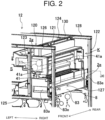
- FIG. 2 is a perspective view illustrating a state where the fixing unit 8 is installed in the fixing unit housing part 2e
- FIG. 3 is a front view illustrating such state
- FIG. 4 is a front view illustrating a state where the fixing unit 8 is removed from the fixing unit housing part 2e.
- the fixing unit housing part 2e is provided in a lower portion of an inside space K of a protruding frame part 120 provided on the body frame 12.
- the protruding frame part 120 is adjacent to the right of the in-body paper discharge space S and is provided over the whole of the body frame 12 in the front and rear direction.
- the protruding frame part 120 is assembled from frame members in the form of a perpendicular parallelepiped.
- the protruding frame part 120 includes a front side right column 121, a rear side right column 122, a front side left column 123, and a rear side left column 124 arranged at four corners in plane vision.
- the front side right column 121 and the rear side right column 122 are adjacent to the fixing unit housing part 2e at the right of this part, and are spaced apart in the front and rear direction.
- the front side left column 123 and the rear side left column 124 are adjacent to the fixing unit housing part 2e at the left of this part, and are spaced apart in the front and rear direction.
- the front side right column 121 and the rear side right column 122 serve as a pair of columns for positioning the fixing unit 8 in the left and right direction.
- the front side right column 121 and the front side left column 123 are coupled to each other by a lower coupling beam 125 and an upper coupling beam 126 each extending in the left and right direction.
- the front side right column 121, the front side left column 123, the lower coupling beam 125, and the upper coupling beam 126 cooperate with one another to form a rectangular frame part extending in an up and down direction.
- the inside of this rectangular frame part constitutes an insertion port 2g for inserting the fixing unit 8 into the fixing unit housing part 2e.
- the insertion port 2g is also used as a port for inserting and withdrawing a discharge unit 40.
- the fixing unit 8 is so formed as to be insertable into and withdrawable from the fixing unit housing part 2e through the insertion port 2g. An inserting and withdrawing direction of the fixing unit 8 agrees with a front and rear direction of the image formation device 1.
- the rear side right column 122 and the rear side left column 124 are coupled to each other by a lower coupling beam 127 and an upper coupling beam 128 each extending in the left and right direction.
- the rear side right column 122, the rear side left column 124, the lower coupling beam 127, and the upper coupling beam 128 cooperate with one another to form a rectangular frame part extending in the up and down direction.
- a drive unit 100 for rotatively driving the pressure roller 82 of the fixing unit 8 is arranged inside this rectangular frame part.
- the upper coupling beam 126 on the front side and the upper coupling beam 128 on the rear side are coupled to each other by a front and rear beam 130 (see FIG. 2 ) extending in the front and rear direction.
- the discharge unit 40 including the paper discharge roller pair 11 is housed.
- the fixing unit housing part 2e is formed of a bottom space lower than the paper discharge roller pair 11 in the inside space K.
- the discharge unit 40 includes the paper discharge roller pair 11 and a support frame 41 supporting the paper discharge roller pair 11.
- the support frame 41 includes opposite plates 41a making a pair that support both axial end portions of the paper discharge roller pair 11, a vertical plate 41b that couples left end portions of the opposite plates 41a making a pair to each other and extends in the up and down direction, and a horizontal protrusion plate 41c that horizontally protrudes from a lower end portion of the vertical plate 41b to the right side.
- an IH (induction heating) heating unit 50 to heat the fixing roller 81 is supported.
- An opening 41d that the IH heating unit 50 passes through is formed in the vertical plate 41b.
- a right side edge portion of the horizontal protrusion plate 41c supports a left side edge portion of a bottom face of the fixing unit 8 slidably in the front and rear direction.
- FIG. 6 is a vertical cross-sectional view of central portions in the front and rear direction of the fixing unit 8 and the IH heating unit 50.
- the fixing unit 8 includes the fixing roller 81 and the pressure roller 82 as described above, and a fixing case 83.
- the fixing roller 81 and the pressure roller 82 are each formed in nearly cylindrical shape elongated in the front and rear direction.
- the fixing roller 81 is provided with an elastic layer 81b formed on a peripheral face of a metallic core rod 81a, and a fixing belt 81c covering a peripheral face of the elastic layer 81b.
- the pressure roller 82 is provided with an elastic layer 82b formed on a peripheral face of a core rod 82a, and a mold release layer 82c covering a peripheral face of the elastic layer 82b.
- the fixing case 83 is formed in nearly rectangular-parallelepipedic shape elongated in the front and rear direction.
- a paper sheet inlet 83c for accepting the paper sheet P conveyed from an upstream side of the paper sheet conveyance path T is formed.
- a paper sheet outlet 83d for discharging the paper sheet P having passed through the fixing roller 81 and the pressure roller 82 is formed.
- an opening 83b in rectangular shape extending in the left and right direction is formed, and a left side half portion of the fixing roller 81 is exposed out of the fixing case 83 through the opening 83b.
- the IH heating unit 50 is provided on a side (left side) of the fixing roller 81 opposite to a nipping part N side.
- the IH heating unit 50 includes a holder 50a in semicylindrical shape opening toward the fixing roller 81, a plurality of IH coils 50b supported by the holder 50a, and an arch core 50c formed of a ferromagnetic material such as ferrite that covers the IH coils 50b.
- An inner face of the holder 50a shapes a concave portion 50g in semicylindrical shape.
- a facial portion of the fixing roller 81 on the side opposite to the nipping part N side comes into the concave portion 50g.
- Both the holder 50a and the arch core 50c face the fixing roller 81 and are so provided as to extend over the whole of the fixing roller 81 in the front and rear direction.
- the pressure roller 82 receives a driving force from the drive unit 100 to be described later and rotates on an axis.
- the fixing roller 81 moves following the pressure roller 82 and rotates on an axis.
- Each IH coil 50b is fed with electricity from a power source (not illustrated) so as to generate a high frequency magnetic field and heat the fixing belt 81c.
- the fixing roller 81 heats, while rotating, the toner images on the paper sheet P passing through a nipping part N.
- the pressure roller 82 puts, while rotating, the paper sheet P passing through the nipping part N under pressure. As a result, the toner images are fixed to the paper sheet P.
- a hold 83a in concave shape is formed at a front side face of the fixing case 83.
- An operator slides the fixing case 83 rearward and forward with fingers laid on the hold 83a, so as to insert and withdraw the fixing unit 8 with respect to the fixing unit housing part 2e.
- a front side end portion of the fixing case 83 is supported by the lower coupling beam 125 on the front side from below, and a rear side end portion of the fixing case 83 is supported by the lower coupling beam 127 on the rear side from below, as illustrated in FIG. 2 .
- a left side edge portion of the fixing unit 8 is supported by the horizontal protrusion plate 41c (only illustrated in FIG. 5 ) of the discharge unit 40.
- a position in the left and right direction (position in a direction orthogonal to the inserting and withdrawing direction) of the fixing case 83 is settled if a right side face of the fixing case 83 abuts the front side right column 121 and the rear side right column 122.
- abutment seats 83e in flat, rectangular shape elongated in the front and rear direction are protrusively provided, respectively. End faces on a protrusion side of the abutment seats 83e are so formed as to be higher in surface roughness and flatness than any other part on the right side face of the fixing case 83.
- a front side supported part 83f to be supported by the lower coupling beam 125 on the front side is formed in a front side end portion of the bottom face of the fixing case 83.
- the front side supported part 83f is constituted of a plurality of rib plates 83h spaced apart in the left and right direction.
- a rear side supported part 83g to be supported by the coupling beam 127 on the rear side is formed in a rear side end portion of the bottom face of the fixing case 83.
- the rear side supported part 83g is constituted of a plurality of rib plates 83i spaced apart in the left and right direction.
- the supported parts 83f and 83g are formed with the rib plates 83h and the rib plates 83i, respectively, so as to reduce frictional force generated between the coupling beams 125 and 127 on the front and rear sides and the fixing case 83 at the time of insertion and withdrawal of the fixing case 83.
- a front side insertion regulator 83j is provided in a portion of the fixing case 83 adjacent to the front of the front side supported part 83f.
- the front side insertion regulator 83j is constituted of a lower end portion of a front side wall of the fixing case 83 and protrudes downward beyond lower edges of the respective rib plates 83h.
- a rear side insertion regulator 83k protruding downward beyond lower edges of the respective rib plates 83i is formed.
- the front side insertion regulator 83j and the rear side insertion regulator 83k abut the lower coupling beam 125 on the front side and the lower coupling beam 127 on the rear side, respectively, so as to regulate excessive forcing in (insertion) of the fixing unit 8 and regulate the fixing unit 8 in a specified position in the front and rear direction.
- a rear end portion of the fixing unit 8 is coupled to the drive unit 100 (see the two-dot chain lines in FIG. 9 ) in a manner allowing power transmission.
- the drive unit 100 includes a case member 101 that is flat in the front and rear direction, a driving gear 14 supported on a shaft 102 protruding from a front side wall of the case member 101 toward the front side, a driving gear train not illustrated that is housed in the case member 101, and a motor (drive source) not illustrated that rotatively drives the driving gear 14 through the driving gear train.
- the driving gear 14 engages with a pressure roller gear 84 (an example of a driven gear).
- the pressure roller gear 84 is integrally-rotatably secured to the core rod 82a of the pressure roller 82.
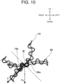
- FIG. 10 is a schematic diagram illustrating a state where the pressure roller gear 84 engages with the driving gear 14, as viewed in an axial direction.
- a line indicated with a two-dot chain line is a common tangent to a tooth flank 14a of the driving gear 14 and a tooth flank 84a of the pressure roller gear 84 in an engagement position M
- a solid line arrow indicates a normal direction of the common tangent and represents, as a vector, a transmission force F transmitted from the tooth flank 14a of the driving gear 14 to the tooth flank 84a of the pressure roller gear 84.
- the transmission force F is leaning downward to the right side (the left in FIGS. 9 and 10 , namely, the side where the front side right column 121 and the rear side right column 122 are located). Therefore, the transmission force F has a horizontal component Fh that horizontally presses the fixing unit 8 against the front side right column 121 and the rear side right column 122, and a vertical component (force component vertically directed downward) Fv that presses the fixing unit 8 against the lower coupling beam 125 and the lower coupling beam 127.
- the horizontal component Fh and the vertical component Fv of the transmission force F are equal to each other.
- An extension line of the transmission force F passes a position at a specified distance ⁇ above in a vertical direction from a crossing position C where a vertical plane A including faces on a fixing unit housing part 2e side of the right columns 121 and 122 in the front and the rear and a horizontal plane B including upper faces of the lower coupling beams 125 and 127 in the front and the rear cross each other.
- the specified distance ⁇ is set to 1/6 or more but not more than 1/5 of the height of the fixing case 83, for instance.
- the fixing unit 8 is pressed by the horizontal component Fh of the transmission force F transmitted from the driving gear 14 to the pressure roller gear 84 against the front side right column 121 and the rear side right column 122 and thus positioned.
- FIG. 11 is a schematic plan view illustrating a state where the fixing unit 8 is pressed against the front side right column 121 and the rear side right column 122.
- the abutment seats 83e in the front and the rear of the fixing case 83 abut the front side right column 121 and the rear side right column 122, respectively from the left side, so as to position the fixing unit 8 in the left and right direction.
- the front side right column 121 and the rear side right column 122 are so formed as to abut the abutment seats 83e in the front and the rear, respectively, not in surface contact but in line contact.
- the front side right column 121 and the rear side right column 122 each have four corners W each formed in the shape of a circular arc and arched recesses V each provided in a central portion in a width direction of a side face, as viewed in a cross section perpendicular to a column length direction illustrated in FIG. 12 .
- a ridge R extending in the column length direction is formed in either end position of each recess V (position of boundary between the relevant recess V and the shape of a circular arc of an adjacent corner W).
- square pipes that are the same in cross-sectional shape as the front side right column 121 and the rear side right column 122 are used for all the columns and lateral beams constituting the body frame 12. Consequently, accuracy in positioning the fixing unit 8 with the lower coupling beam 125 (see FIG. 2 ) on the front side and the lower coupling beam 127 on the rear side in the up and down direction, for instance, is also improved.
- a skeletal frame of the image formation device 1 includes the front side right column 121 and the rear side right column 122, which are so arranged as to be adjacent to the fixing unit housing part 2e and spaced apart in the inserting and withdrawing direction of the fixing unit 8, and the lower coupling beam 125 and the lower coupling beam 127, which are orthogonally connected to the front side right column 121 and the rear side right column 122, respectively, as viewed in the inserting and withdrawing direction and support the bottom face of the fixing unit 8.
- the image formation device 1 includes: the pressure roller gear 84 integrally-rotatably coupled to a far end portion in the inserting and withdrawing direction of the pressure roller 82 of the fixing unit 8; the driving gear 14, which is provided in a far end portion in the inserting and withdrawing direction of the fixing unit housing part 2e and engages with the pressure roller gear 84 when the fixing unit 8 is housed in the fixing unit housing part 2e; and the drive source (not illustrated) to rotatively drive the driving gear 14.
- the driving gear 14 and the pressure roller gear 84 are formed so that, during the power transmission, the transmission force F transmitted from the tooth flank 14a of the driving gear 14 to the tooth flank 84a of the pressure roller gear 84 in the engagement position M of mutual engagement has the horizontal component Fh so directed as to horizontally press the fixing unit 8 against the front side right column 121 and the rear side right column 122.
- the fixing unit 8 as housed in the fixing unit housing part 2e is pressed by the horizontal component Fh of the transmission force F against the front side right column 121 and the rear side right column 122 and positioned in the direction (left and right direction) orthogonal to the inserting and withdrawing direction.
- the fixing unit 8 is pressed by the transmission force F transmitted from the driving gear 14 to the pressure roller gear 84 against the front side right column 121 and the rear side right column 122 and thus positioned simply by inserting the fixing unit 8 into the fixing unit housing part 2e from the front side so as to cause the image formation device 1 to perform a printing process. Consequently, structure is simplified as compared with a positioning structure where an engagement groove and an engagement pin are engaged with each other as in a conventional image formation device. It is unnecessary to additionally provide a biasing mechanism for securing the fixing unit 8 and a release mechanism for releasing the securing, so that the number of parts is decreased for the reduction in costs.
- the driving gear 14 and the pressure roller gear 84 are formed so that, during the power transmission, the extension line of the transmission force F passes above the crossing position C where the vertical plane A, which includes the faces on the fixing unit housing part 2e side of the right columns 121 and 122 in the front and the rear, and the horizontal plane B, which includes the upper faces of the lower coupling beams 125 and 127 in the front and the rear, cross each other, as viewed in the inserting and withdrawing direction of the fixing unit 8 (see FIG. 9 ).
- the transmission force F generates a moment so directed as to cause the fixing unit 8 to rotate counterclockwise in FIG. 9 on the crossing position C as a fulcrum.
- a side face on the right side (the left in FIG. 9 ) of the fixing unit 8 is surely pressed against the front side right column 121 and the rear side right column 122 so as to improve, as much as possible, accuracy in positioning the fixing unit 8 in the left and right direction.
- the driving gear 14 and the pressure roller gear 84 are formed so that, during the power transmission, the horizontal component Fh and the vertical component Fv of the transmission force F are equal to each other.
- the fixing unit 8 is equally pressed rightward in a horizontal direction and downward in the vertical direction. Consequently, the fixing unit 8 is prevented from coming up from the lower coupling beams 125 and 127 as a result of excessive pressing of the fixing unit 8 against the front side right column 121 and the rear side right column 122. Moreover, the accuracy in positioning the fixing unit 8 is improved both in the left and right direction and in the up and down direction.
- the faces on the fixing unit housing part 2e side of the front side right column 121 and the rear side right column 122 are each so formed as to have two ridges R extending in the up and down direction and spaced apart in the inserting and withdrawing direction.
- the fixing unit 8 is so formed as to abut the two ridges R provided on each of the front side right column 121 and the rear side right column 122 when pressed by the horizontal component Fh of the transmission force F against the right columns 121 and 122.
- the fixing unit 8 abuts the front side right column 121 and the rear side right column 122 in line contact, so that the positioning in the left and right direction is performed with high accuracy as compared with the case of abutment in surface contact.
- the abutment seats 83e making a pair, which abut the front side right column 121 and the rear side right column 122, respectively, are protrusively provided.
- the abutment seats 83e are each so formed as to be able to abut the two ridges R provided on one of the front side right column 121 and the rear side right column 122 when the fixing unit 8 is pressed against the right columns 121 and 122.
- the abutment seats 83e each have a width set larger than the distance between the two ridges R.
- faces on the protrusion side of the abutment seats 83e are so formed as to be higher in surface precision than any other part, and the faces on the protrusion side of the protruding seats 83e higher in surface precision are caused to abut the ridges R of the front side right column 121 and the rear side right column 122 so as to improve, as much as possible, accuracy in positioning the fixing case 83 in the left and right direction.
- FIG. 13 illustrates Modification 1 of the embodiment as described above.
- the same constituent elements as the constituent elements in FIG. 9 are given the same reference numerals and not detailed.
- the driving gear 14 and the pressure roller gear 84 are formed so that, during the power transmission, the extension line of the transmission force F passes the crossing position C where the vertical plane A, which includes the faces on the fixing unit housing part 2e side of the right columns 121 and 122 in the front and the rear, and the horizontal plane B, which includes the upper faces of the lower coupling beams 125 and 127 in the front and the rear, cross each other, as viewed in the inserting and withdrawing direction of the fixing unit 8.
- the extension line of the transmission force F passes the crossing position C as viewed in the inserting and withdrawing direction of the fixing unit 8, so that a moment about the crossing position C that acts on the fixing unit 8 is not generated. Consequently, a posture of the fixing unit 8 is prevented from dynamically changing due to a moment load caused by the transmission force F and, moreover, the accuracy in positioning the fixing unit 8 is improved in the left and right direction and the up and down direction.
- FIG. 14 illustrates Modification 2 of the embodiment as described above.
- the driving gear 14 and the pressure roller gear 84 are formed so that, during the power transmission, the horizontal component Fh of the transmission force F is larger than the vertical component Fv.
- the fixing unit 8 is pressed against the front side right column 121 and the rear side right column 122 more firmly as compared with the case where the horizontal component Fh and the vertical component Fv are equal to each other, so as to improve the accuracy in positioning the fixing unit 8 in the left and right direction.
- the vertical component Fv pressing the fixing unit 8 downward is reduced indeed, but the fixing unit 8 can be pressed against the lower coupling beams 125 and 127 in the front and the rear by gravity acting on the fixing unit 8 even if the vertical component Fv is small, so that the accuracy in positioning the fixing unit 8 in the up and down direction is not impaired.
- the pressure roller 82 is assumed as a driving roller and the fixing roller 81 is assumed as a driven roller, to which the present invention is not limited, and the fixing roller 81 may be a driving roller and the pressure roller 82 may be a driven roller.
- the driven gear may integrally-rotatably be coupled to a drive shaft of the fixing roller 81 and the driving gear 14 may be engaged with such driven gear.
- the fixing roller 81 has been described as an exemplary rotary fixing member, while the rotary fixing member is not limited to such roller but may be a fixing belt in an endless form.
- the pressure roller 82 has been described as an exemplary rotary pressure member, while the rotary pressure member is not limited to such roller but may be a pressure belt in an endless form.
- the image formation device 1 may be a printer, a facsimile machine, a copying machine or a multifunction peripheral (MFP).
- MFP multifunction peripheral
- the present invention is useful for image formation devices, and particularly useful if applied to a printer, a facsimile machine, a copying machine or a multifunction peripheral (MFP).
- MFP multifunction peripheral
Landscapes
- Physics & Mathematics (AREA)
- General Physics & Mathematics (AREA)
- Engineering & Computer Science (AREA)
- Computer Vision & Pattern Recognition (AREA)
- Electrophotography Configuration And Component (AREA)
- Fixing For Electrophotography (AREA)
Abstract
Description
- The present invention relates to an image formation device.
- An electrophotographic image formation device generally includes a fixing unit to fix a toner image to a sheet with a fixing roller and a pressure roller that are brought into pressure contact with each other and as such rotated. In such fixing unit, the toner image on the sheet is heated and put under pressure when the sheet passes through a nipping part formed between the fixing roller and the pressure roller, so as to fix the toner image to the sheet.
- The fixing unit normally includes a housing that the fixing roller and the pressure roller are housed in. The housing is detachably attached to an image formation device body. Patent Literature 1 discloses an exemplary structure allowing the fixing unit to be attached to and detached from the image formation device body.
- In an image formation device in the patent literature, an attaching and detaching direction of the fixing unit is set as a direction orthogonal to a longitudinal direction of the housing (an axial direction of the fixing roller). On either side face in a longitudinal direction of the housing, an engagement pin is protrusively provided. The image formation device body is provided with a pressing member that engages with the respective engagement pins and presses the fixing unit in an attaching direction against the image formation device body with a biasing force of a biasing member when the fixing unit is attached to the image formation device body. The pressing member is arranged pivotably on a specified axis, and the engagement between the pressing member and the engagement pins is released by operating an operation lever.
- PTL1:
JP 2013-072987 A - As seen from Patent Literature 1, in a conventional positioning structure where the engagement pin provided on the fixing unit is to be engaged with an engagement groove provided on the image formation device body, the engagement groove needs to be made large in diameter as compared with the engagement pin in order to ensure attachability and detachability of the fixing unit. A problem, however, arises in that accuracy in positioning the fixing unit deteriorates if the engagement groove is made large in diameter as compared with the engagement pin.
- For the conventional positioning structure as above, it is necessary to additionally provide a biasing mechanism (such as the biasing member) for securing the fixing unit to the image formation device body, and a release mechanism (such as the operation lever) for releasing the securing of the fixing unit. Such necessity increases the number of parts, leading to the increase in costs.
- The present invention has been made in view of the above points, and is aimed at positioning the fixing unit with high accuracy and ensuring a good attachability and a good detachability of the fixing unit while keeping the number of parts small.
- An image formation device according to the present invention includes a fixing unit that causes a sheet carrying a toner image to pass through a nipping part formed by bringing a rotary fixing member and a rotary pressure member into pressure contact with each other, so as to fix the toner image to the sheet, and an image formation device body having a fixing unit housing part that the fixing unit is to be removably housed in.
- An inserting and withdrawing direction of the fixing unit with respect to the fixing unit housing part agrees with an axial direction of the rotary pressure member, and a skeletal frame of the image formation device includes columns making a pair that are so arranged as to be adjacent to the fixing unit housing part and spaced apart in the inserting and withdrawing direction of the fixing unit, and lateral beams making a pair that are orthogonally connected to the columns making a pair, respectively, as viewed in the inserting and withdrawing direction and support a bottom face of the fixing unit. The image formation device includes: a driven gear integrally-rotatably coupled to a far end portion in the inserting and withdrawing direction of the rotary fixing member or the rotary pressure member of the fixing unit; a driving gear provided in a far end portion in the inserting and withdrawing direction of the fixing unit housing part and configured to engage with the driven gear when the fixing unit is housed in the fixing unit housing part; and a drive source to rotatively drive the driving gear. The driving gear and the driven gear are formed so that, during power transmission, a transmission force transmitted from a tooth flank of the driving gear to a tooth flank of the driven gear in a mutual engagement position has a component so directed as to horizontally press the fixing unit against the columns making a pair, and the fixing unit as housed in the fixing unit housing part is pressed by the transmission force against the columns making a pair, and positioned in a direction orthogonal to the inserting and withdrawing direction.
- According to the present invention, it is possible with a small number of parts to position the fixing unit with high accuracy and ensure a good attachability and a good detachability of the fixing unit.
-
- [
FIG. 1] FIG. 1 is a schematic diagram illustrating an image formation device in an embodiment. - [
FIG. 2] FIG. 2 is a perspective view of a right end portion of a body frame as obliquely viewed from a front right side, illustrating a state where a fixing unit is installed in a fixing unit housing part. - [
FIG. 3] FIG. 3 is a front view of the right end portion of the body frame as viewed from a front side, illustrating the state where the fixing unit is installed in the fixing unit housing part. - [
FIG. 4] FIG. 4 is a front view of the right end portion of the body frame as viewed from the front side, illustrating a state where the fixing unit is removed from the fixing unit housing part. - [
FIG. 5] FIG. 5 is a front view of a discharge unit as viewed from the front side. - [
FIG. 6] FIG. 6 is a cross-sectional view of a central portion of the fixing unit, taken at a vertical plane extending in a left and right direction. - [
FIG. 7] FIG. 7 is a perspective view of the fixing unit as obliquely viewed from the front right side. - [
FIG. 8] FIG. 8 is a perspective view of the fixing unit as obliquely viewed from a front lower right. - [
FIG. 9] FIG. 9 is a rear view of the right end portion of the body frame as viewed from a rear side, illustrating part of a drive unit for driving the fixing unit with imaginary lines and a driving gear with a solid line. - [FIG. 101
FIG. 10 is an enlarged view illustrating, in an enlarged manner, vicinity of a position where the driving gear and a pressure roller gear engage with each other. - [
FIG. 11] FIG. 11 is a cross-sectional view taken along a line XI-XI inFIG. 2 . - [
FIG. 12] FIG. 12 is a cross-sectional view illustrating a cross-sectional shape of columns and lateral beams constituting a protruding frame part. - [
FIG. 13] FIG. 13 is a view corresponding toFIG. 9 , illustrating Modification 1. - [
FIG. 14] FIG. 14 is a view corresponding toFIG. 9 , illustratingModification 2. - In the following, an embodiment of the present invention is described in detail, based on the drawings. The present invention is not limited to the embodiment described below.
-
FIG. 1 is a schematic configurational diagram illustrating an image formation device 1 in an embodiment. In the description below, a front side and a rear side refer to a front side and a rear side of the image formation device 1 (ahead of and behind a drawing plane ofFIG. 1 in a direction perpendicular to the drawing plane), respectively, and a left side and a right side refer to a left side and a right side of the image formation device 1 as viewed from the front side, respectively. - The image formation device 1 is a copying machine of an in-body paper discharge type, and includes an image
formation device body 2 and animage reader 3 provided above the imageformation device body 2. Theimage reader 3 optically reads an original image and generates image data of the original image. - An image forming section 4 to transfer and form an image on a paper sheet P (an example of a sheet) based on the image data of the original read by the
image reader 3 is provided in the imageformation device body 2. Above the image forming section 4, atransfer unit 6 is arranged. Thetransfer unit 6 includes anintermediate transfer belt 6a in an endless form extending in a left and right direction, and fourprimary transfer rollers 6b so arranged inside theintermediate transfer belt 6a as to align with one another in the left and right direction. -
Exposure equipment 5 that emits laser light is arranged below the image forming section 4. Below theexposure equipment 5, apaper feeding section 7, where the paper sheet P is stored, is arranged. Afixing unit 8 that performs a fixing treatment on the image transferred and formed on the paper sheet P is arranged at an upper right of thetransfer unit 6. An in-body paper discharge space S, where the paper sheet P as subjected to the fixing treatment by thefixing unit 8 is discharged, is provided between the imageformation device body 2 and theimage reader 3. - A paper discharge tray
part 9 for receiving the paper sheet P discharged into the in-body paper discharge space S is formed at a top face of the imageformation device body 2. In the imageformation device body 2, a paper sheet conveyance path T extending from thepaper feeding section 7 toward the paperdischarge tray part 9 is provided. Asecondary transfer roller 10 facing adriving roller 6c for theintermediate transfer belt 6a across the belt is provided below thefixing unit 8 on the paper sheet conveyance path T. A paperdischarge roller pair 11 that discharges the paper sheet P toward the paperdischarge tray part 9 nearly horizontally is provided above thefixing unit 8 on the paper sheet conveyance path T. - In a right side face of the image
formation device body 2 adjacent to the paper sheet conveyance path T, an opening 2a in rectangular shape is formed. The opening 2a is closable with anopenable cover 2b. Theopenable cover 2b is pivotably supported on asupport shaft 2f extending along a lower edge of the opening 2a. Theopenable cover 2b in a closed state is pivoted on thesupport shaft 2f toward the right side and thus opened. A jamming paper sheet having blocked the paper sheet conveyance path T can be disposed by opening theopenable cover 2b. - The image forming section 4 includes
drum units 20 anddevelopment units 30 provided for yellow, magenta, cyan, and black colors, respectively. Thedrum units 20 each include aphotosensitive drum 21 that is rotatable. A surface of thephotosensitive drum 21 is irradiated with laser light from theexposure equipment 5 based on specified image data so as to form an electrostatic latent image on the surface. - The
development units 30 each include adevelopment vessel 31 and adevelopment roller 32. Eachdevelopment vessel 31 is fed with toner as a developer from a toner container (not illustrated) for a corresponding color and contains the toner. Thedevelopment roller 32 is so formed as to be rotatable while exposed through a right side wall of an upper portion of thedevelopment vessel 31. Thedevelopment roller 32 generates a potential difference between thedevelopment roller 32 itself and the surface of thephotosensitive drum 21 so as to cause the toner to fly to the surface of thephotosensitive drum 21. The electrostatic latent image on the surface of thephotosensitive drum 21 is developed with the toner flying from thedevelopment roller 32 and thus visualized. - Toner images in the respective colors on the respective
photosensitive drums 21 as visualized by thedevelopment units 30 are sequentially transferred to theintermediate transfer belt 6a under bias applied by theprimary transfer rollers 6b arranged above the respectivephotosensitive drums 21, and superposed on one another. The superposed toner images are transferred to the paper sheet P fed from thepaper feeding section 7 when the paper sheet P passes between theintermediate transfer belt 6a and thesecondary transfer roller 10. The paper sheet P, to which the toner images have been transferred, is sent to the fixingunit 8. - The fixing
unit 8 includes a fixingroller 81 and apressure roller 82 that face each other in the left and right direction across the paper sheet conveyance path T. The fixingunit 8 holds and conveys the paper sheet P carrying the toner images with the fixingroller 81 and thepressure roller 82. The toner images on the paper sheet P are heated and put under pressure during the passing between the fixingroller 81 and thepressure roller 82, so as to thermally fix the toner images to the paper sheet P. The paper sheet P, to which the toner images have thermally been fixed, is discharged to the paperdischarge tray part 9 by the paperdischarge roller pair 11 arranged above the fixingunit 8. - Next, a structure for housing the fixing
unit 8 in the imageformation device body 2 is described. - The image
formation device body 2 includes abody frame 12 formed by combining a plurality of columns and lateral beams of metal (seeFIG. 2 and the like), and exterior covers (not illustrated) covering side faces of thebody frame 12, respectively. The columns and lateral beams are formed of hollow pipes with a cross section in substantially rectangular shape, for instance. - In an upper right portion of an exterior cover covering a front side face of the
body frame 12, an openable maintenance door 13 (only illustrated inFIG. 1 ) is provided. A fixingunit housing part 2e that the fixingunit 8 is to be removably housed in is provided in a place opposite to an inside face of themaintenance door 13. The fixingunit housing part 2e is constituted of a hollow, spatial part extending in a front and rear direction, and has a front side end portion (one side end portion) where an insertion andwithdrawal port 2g for inserting and withdrawing the fixingunit 8 is provided. - Referring to
FIGS. 2 through 4 , the fixingunit housing part 2e is detailed. In the respective figures, the exterior covers and themaintenance door 13 are not illustrated.FIG. 2 is a perspective view illustrating a state where the fixingunit 8 is installed in the fixingunit housing part 2e,FIG. 3 is a front view illustrating such state, andFIG. 4 is a front view illustrating a state where the fixingunit 8 is removed from the fixingunit housing part 2e. - The fixing
unit housing part 2e is provided in a lower portion of an inside space K of a protrudingframe part 120 provided on thebody frame 12. The protrudingframe part 120 is adjacent to the right of the in-body paper discharge space S and is provided over the whole of thebody frame 12 in the front and rear direction. The protrudingframe part 120 is assembled from frame members in the form of a perpendicular parallelepiped. - Specifically, the protruding
frame part 120 includes a front sideright column 121, a rear sideright column 122, a front side leftcolumn 123, and a rear side leftcolumn 124 arranged at four corners in plane vision. The front sideright column 121 and the rear sideright column 122 are adjacent to the fixingunit housing part 2e at the right of this part, and are spaced apart in the front and rear direction. The front side leftcolumn 123 and the rear side leftcolumn 124 are adjacent to the fixingunit housing part 2e at the left of this part, and are spaced apart in the front and rear direction. The front sideright column 121 and the rear sideright column 122 serve as a pair of columns for positioning thefixing unit 8 in the left and right direction. - The front side
right column 121 and the front side leftcolumn 123 are coupled to each other by alower coupling beam 125 and anupper coupling beam 126 each extending in the left and right direction. The front sideright column 121, the front side leftcolumn 123, thelower coupling beam 125, and theupper coupling beam 126 cooperate with one another to form a rectangular frame part extending in an up and down direction. The inside of this rectangular frame part constitutes aninsertion port 2g for inserting the fixingunit 8 into the fixingunit housing part 2e. Theinsertion port 2g is also used as a port for inserting and withdrawing adischarge unit 40. The fixingunit 8 is so formed as to be insertable into and withdrawable from the fixingunit housing part 2e through theinsertion port 2g. An inserting and withdrawing direction of the fixingunit 8 agrees with a front and rear direction of the image formation device 1. - The rear side
right column 122 and the rear side leftcolumn 124 are coupled to each other by alower coupling beam 127 and anupper coupling beam 128 each extending in the left and right direction. The rear sideright column 122, the rear side leftcolumn 124, thelower coupling beam 127, and theupper coupling beam 128 cooperate with one another to form a rectangular frame part extending in the up and down direction. Inside this rectangular frame part, a drive unit 100 (see two-dot chain lines inFIG. 9 ) for rotatively driving thepressure roller 82 of the fixingunit 8 is arranged. In the protrudingframe part 120, theupper coupling beam 126 on the front side and theupper coupling beam 128 on the rear side are coupled to each other by a front and rear beam 130 (seeFIG. 2 ) extending in the front and rear direction. - In the inside space K of the protruding
frame part 120, thedischarge unit 40 including the paperdischarge roller pair 11 is housed. The fixingunit housing part 2e is formed of a bottom space lower than the paperdischarge roller pair 11 in the inside space K. - As illustrated in
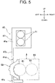
FIG. 5 , thedischarge unit 40 includes the paperdischarge roller pair 11 and asupport frame 41 supporting the paperdischarge roller pair 11. Thesupport frame 41 includesopposite plates 41a making a pair that support both axial end portions of the paperdischarge roller pair 11, avertical plate 41b that couples left end portions of theopposite plates 41a making a pair to each other and extends in the up and down direction, and ahorizontal protrusion plate 41c that horizontally protrudes from a lower end portion of thevertical plate 41b to the right side. On an upper face of thehorizontal protrusion plate 41c, an IH (induction heating)heating unit 50 to heat the fixingroller 81 is supported. Anopening 41d that theIH heating unit 50 passes through is formed in thevertical plate 41b. At the time of insertion and withdrawal of the fixingunit 8, a right side edge portion of thehorizontal protrusion plate 41c supports a left side edge portion of a bottom face of the fixingunit 8 slidably in the front and rear direction. -
FIG. 6 is a vertical cross-sectional view of central portions in the front and rear direction of the fixingunit 8 and theIH heating unit 50. The fixingunit 8 includes the fixingroller 81 and thepressure roller 82 as described above, and a fixingcase 83. - The fixing
roller 81 and thepressure roller 82 are each formed in nearly cylindrical shape elongated in the front and rear direction. The fixingroller 81 is provided with anelastic layer 81b formed on a peripheral face of ametallic core rod 81a, and a fixingbelt 81c covering a peripheral face of theelastic layer 81b. Thepressure roller 82 is provided with anelastic layer 82b formed on a peripheral face of acore rod 82a, and amold release layer 82c covering a peripheral face of theelastic layer 82b. - The fixing
case 83 is formed in nearly rectangular-parallelepipedic shape elongated in the front and rear direction. In a bottom face of the fixingcase 83, apaper sheet inlet 83c for accepting the paper sheet P conveyed from an upstream side of the paper sheet conveyance path T is formed. In a top face of the fixingcase 83, apaper sheet outlet 83d for discharging the paper sheet P having passed through the fixingroller 81 and thepressure roller 82 is formed. In a left side wall of the fixingcase 83, anopening 83b in rectangular shape extending in the left and right direction is formed, and a left side half portion of the fixingroller 81 is exposed out of the fixingcase 83 through theopening 83b. - The
IH heating unit 50 is provided on a side (left side) of the fixingroller 81 opposite to a nipping part N side. TheIH heating unit 50 includes aholder 50a in semicylindrical shape opening toward the fixingroller 81, a plurality ofIH coils 50b supported by theholder 50a, and anarch core 50c formed of a ferromagnetic material such as ferrite that covers the IH coils 50b. An inner face of theholder 50a shapes aconcave portion 50g in semicylindrical shape. In the state where theIH heating unit 50 is in a heating position, a facial portion of the fixingroller 81 on the side opposite to the nipping part N side comes into theconcave portion 50g. Both theholder 50a and thearch core 50c face the fixingroller 81 and are so provided as to extend over the whole of the fixingroller 81 in the front and rear direction. - During the fixing treatment, the
pressure roller 82 receives a driving force from thedrive unit 100 to be described later and rotates on an axis. The fixingroller 81 moves following thepressure roller 82 and rotates on an axis. EachIH coil 50b is fed with electricity from a power source (not illustrated) so as to generate a high frequency magnetic field and heat the fixingbelt 81c. The fixingroller 81 heats, while rotating, the toner images on the paper sheet P passing through a nipping part N. Thepressure roller 82 puts, while rotating, the paper sheet P passing through the nipping part N under pressure. As a result, the toner images are fixed to the paper sheet P. - As illustrated in
FIGS. 7 and8 , ahold 83a in concave shape is formed at a front side face of the fixingcase 83. An operator slides the fixingcase 83 rearward and forward with fingers laid on thehold 83a, so as to insert and withdraw the fixingunit 8 with respect to the fixingunit housing part 2e. - In the state where the fixing
unit 8 is housed in the fixingunit housing part 2e (state where installation has been completed), a front side end portion of the fixingcase 83 is supported by thelower coupling beam 125 on the front side from below, and a rear side end portion of the fixingcase 83 is supported by thelower coupling beam 127 on the rear side from below, as illustrated inFIG. 2 . A left side edge portion of the fixingunit 8 is supported by thehorizontal protrusion plate 41c (only illustrated inFIG. 5 ) of thedischarge unit 40. - A position in the left and right direction (position in a direction orthogonal to the inserting and withdrawing direction) of the fixing
case 83 is settled if a right side face of the fixingcase 83 abuts the front sideright column 121 and the rear sideright column 122. To be specific: In end portions in the front and rear direction of the right side face of the fixingcase 83,abutment seats 83e in flat, rectangular shape elongated in the front and rear direction are protrusively provided, respectively. End faces on a protrusion side of theabutment seats 83e are so formed as to be higher in surface roughness and flatness than any other part on the right side face of the fixingcase 83. When theabutment seats 83e in the front and the rear abut the front sideright column 121 and the rear sideright column 122, respectively, the fixingcase 83 is positioned in the left and right direction. - As illustrated in
FIG. 8 , a front side supportedpart 83f to be supported by thelower coupling beam 125 on the front side is formed in a front side end portion of the bottom face of the fixingcase 83. The front side supportedpart 83f is constituted of a plurality ofrib plates 83h spaced apart in the left and right direction. A rear side supportedpart 83g to be supported by thecoupling beam 127 on the rear side is formed in a rear side end portion of the bottom face of the fixingcase 83. The rear side supportedpart 83g is constituted of a plurality ofrib plates 83i spaced apart in the left and right direction. The supportedparts rib plates 83h and therib plates 83i, respectively, so as to reduce frictional force generated between the coupling beams 125 and 127 on the front and rear sides and the fixingcase 83 at the time of insertion and withdrawal of the fixingcase 83. - In a portion of the fixing
case 83 adjacent to the front of the front side supportedpart 83f, a frontside insertion regulator 83j is provided. The frontside insertion regulator 83j is constituted of a lower end portion of a front side wall of the fixingcase 83 and protrudes downward beyond lower edges of therespective rib plates 83h. In a portion of the fixingcase 83 adjacent to the front of the rear side supportedpart 83g, a rearside insertion regulator 83k protruding downward beyond lower edges of therespective rib plates 83i is formed. When the fixingunit 8 is inserted into the fixingunit housing part 2e, the frontside insertion regulator 83j and the rearside insertion regulator 83k abut thelower coupling beam 125 on the front side and thelower coupling beam 127 on the rear side, respectively, so as to regulate excessive forcing in (insertion) of the fixingunit 8 and regulate the fixingunit 8 in a specified position in the front and rear direction. In the state where the fixingunit 8 is regulated in the specified position in the front and rear direction, a rear end portion of the fixingunit 8 is coupled to the drive unit 100 (see the two-dot chain lines inFIG. 9 ) in a manner allowing power transmission. - As seen from
FIG. 9 , thedrive unit 100 includes acase member 101 that is flat in the front and rear direction, adriving gear 14 supported on ashaft 102 protruding from a front side wall of thecase member 101 toward the front side, a driving gear train not illustrated that is housed in thecase member 101, and a motor (drive source) not illustrated that rotatively drives thedriving gear 14 through the driving gear train. - When the fixing
unit 8 is housed in the fixingunit housing part 2e, thedriving gear 14 engages with a pressure roller gear 84 (an example of a driven gear). Thepressure roller gear 84 is integrally-rotatably secured to thecore rod 82a of thepressure roller 82. -
FIG. 10 is a schematic diagram illustrating a state where thepressure roller gear 84 engages with thedriving gear 14, as viewed in an axial direction. In the figure, a line indicated with a two-dot chain line is a common tangent to atooth flank 14a of thedriving gear 14 and atooth flank 84a of thepressure roller gear 84 in an engagement position M, and a solid line arrow indicates a normal direction of the common tangent and represents, as a vector, a transmission force F transmitted from thetooth flank 14a of thedriving gear 14 to thetooth flank 84a of thepressure roller gear 84. - The transmission force F is leaning downward to the right side (the left in
FIGS. 9 and10 , namely, the side where the front sideright column 121 and the rear sideright column 122 are located). Therefore, the transmission force F has a horizontal component Fh that horizontally presses the fixingunit 8 against the front sideright column 121 and the rear sideright column 122, and a vertical component (force component vertically directed downward) Fv that presses the fixingunit 8 against thelower coupling beam 125 and thelower coupling beam 127. In the example inFIGS. 9 and10 , the horizontal component Fh and the vertical component Fv of the transmission force F are equal to each other. - An extension line of the transmission force F passes a position at a specified distance δ above in a vertical direction from a crossing position C where a vertical plane A including faces on a fixing
unit housing part 2e side of theright columns lower coupling beams case 83, for instance. - The fixing
unit 8 is pressed by the horizontal component Fh of the transmission force F transmitted from thedriving gear 14 to thepressure roller gear 84 against the front sideright column 121 and the rear sideright column 122 and thus positioned. -
FIG. 11 is a schematic plan view illustrating a state where the fixingunit 8 is pressed against the front sideright column 121 and the rear sideright column 122. As illustrated in this figure, theabutment seats 83e in the front and the rear of the fixingcase 83 abut the front sideright column 121 and the rear sideright column 122, respectively from the left side, so as to position the fixingunit 8 in the left and right direction. - The front side
right column 121 and the rear sideright column 122 are so formed as to abut theabutment seats 83e in the front and the rear, respectively, not in surface contact but in line contact. In other words, the front sideright column 121 and the rear sideright column 122 each have four corners W each formed in the shape of a circular arc and arched recesses V each provided in a central portion in a width direction of a side face, as viewed in a cross section perpendicular to a column length direction illustrated inFIG. 12 . In each of thecolumns unit 8 is pressed against the front sideright column 121 and the rear sideright column 122, therefore, the ridges R of therespective columns case 83, which makes it possible to position the fixingunit 8 with high accuracy as compared with the case of surface contact. - In the present embodiment, square pipes that are the same in cross-sectional shape as the front side
right column 121 and the rear sideright column 122 are used for all the columns and lateral beams constituting thebody frame 12. Consequently, accuracy in positioning thefixing unit 8 with the lower coupling beam 125 (seeFIG. 2 ) on the front side and thelower coupling beam 127 on the rear side in the up and down direction, for instance, is also improved. - As described above, in the present embodiment, the inserting and withdrawing direction (front and rear direction) of the fixing
unit 8 with respect to the fixingunit housing part 2e agrees with an axial direction of thepressure roller 82. A skeletal frame of the image formation device 1 includes the front sideright column 121 and the rear sideright column 122, which are so arranged as to be adjacent to the fixingunit housing part 2e and spaced apart in the inserting and withdrawing direction of the fixingunit 8, and thelower coupling beam 125 and thelower coupling beam 127, which are orthogonally connected to the front sideright column 121 and the rear sideright column 122, respectively, as viewed in the inserting and withdrawing direction and support the bottom face of the fixingunit 8. The image formation device 1 includes: thepressure roller gear 84 integrally-rotatably coupled to a far end portion in the inserting and withdrawing direction of thepressure roller 82 of the fixingunit 8; thedriving gear 14, which is provided in a far end portion in the inserting and withdrawing direction of the fixingunit housing part 2e and engages with thepressure roller gear 84 when the fixingunit 8 is housed in the fixingunit housing part 2e; and the drive source (not illustrated) to rotatively drive the drivinggear 14. Thedriving gear 14 and thepressure roller gear 84 are formed so that, during the power transmission, the transmission force F transmitted from thetooth flank 14a of thedriving gear 14 to thetooth flank 84a of thepressure roller gear 84 in the engagement position M of mutual engagement has the horizontal component Fh so directed as to horizontally press the fixingunit 8 against the front sideright column 121 and the rear sideright column 122. The fixingunit 8 as housed in the fixingunit housing part 2e is pressed by the horizontal component Fh of the transmission force F against the front sideright column 121 and the rear sideright column 122 and positioned in the direction (left and right direction) orthogonal to the inserting and withdrawing direction. - According to the configuration as above, the fixing
unit 8 is pressed by the transmission force F transmitted from thedriving gear 14 to thepressure roller gear 84 against the front sideright column 121 and the rear sideright column 122 and thus positioned simply by inserting the fixingunit 8 into the fixingunit housing part 2e from the front side so as to cause the image formation device 1 to perform a printing process. Consequently, structure is simplified as compared with a positioning structure where an engagement groove and an engagement pin are engaged with each other as in a conventional image formation device. It is unnecessary to additionally provide a biasing mechanism for securing the fixingunit 8 and a release mechanism for releasing the securing, so that the number of parts is decreased for the reduction in costs. - In the present embodiment, the
driving gear 14 and thepressure roller gear 84 are formed so that, during the power transmission, the extension line of the transmission force F passes above the crossing position C where the vertical plane A, which includes the faces on the fixingunit housing part 2e side of theright columns lower coupling beams FIG. 9 ). - According to the configuration as above, the transmission force F generates a moment so directed as to cause the fixing
unit 8 to rotate counterclockwise inFIG. 9 on the crossing position C as a fulcrum. As a result, a side face on the right side (the left inFIG. 9 ) of the fixingunit 8 is surely pressed against the front sideright column 121 and the rear sideright column 122 so as to improve, as much as possible, accuracy in positioning thefixing unit 8 in the left and right direction. - In the present embodiment, the
driving gear 14 and thepressure roller gear 84 are formed so that, during the power transmission, the horizontal component Fh and the vertical component Fv of the transmission force F are equal to each other. - According to the configuration as above, the fixing
unit 8 is equally pressed rightward in a horizontal direction and downward in the vertical direction. Consequently, the fixingunit 8 is prevented from coming up from thelower coupling beams unit 8 against the front sideright column 121 and the rear sideright column 122. Moreover, the accuracy in positioning thefixing unit 8 is improved both in the left and right direction and in the up and down direction. - In the present embodiment, the faces on the fixing
unit housing part 2e side of the front sideright column 121 and the rear sideright column 122 are each so formed as to have two ridges R extending in the up and down direction and spaced apart in the inserting and withdrawing direction. The fixingunit 8 is so formed as to abut the two ridges R provided on each of the front sideright column 121 and the rear sideright column 122 when pressed by the horizontal component Fh of the transmission force F against theright columns - According to the configuration as above, the fixing
unit 8 abuts the front sideright column 121 and the rear sideright column 122 in line contact, so that the positioning in the left and right direction is performed with high accuracy as compared with the case of abutment in surface contact. - In the present embodiment, on the face (right side face in the present embodiment) of the fixing
unit 8, which face is to be pressed against the front sideright column 121 and the rear sideright column 122, theabutment seats 83e making a pair, which abut the front sideright column 121 and the rear sideright column 122, respectively, are protrusively provided. The abutment seats 83e are each so formed as to be able to abut the two ridges R provided on one of the front sideright column 121 and the rear sideright column 122 when the fixingunit 8 is pressed against theright columns abutment seats 83e each have a width set larger than the distance between the two ridges R. - According to the configuration as above, faces on the protrusion side of the
abutment seats 83e are so formed as to be higher in surface precision than any other part, and the faces on the protrusion side of the protrudingseats 83e higher in surface precision are caused to abut the ridges R of the front sideright column 121 and the rear sideright column 122 so as to improve, as much as possible, accuracy in positioning the fixingcase 83 in the left and right direction. -
FIG. 13 illustrates Modification 1 of the embodiment as described above. With respect to the modifications below, the same constituent elements as the constituent elements inFIG. 9 are given the same reference numerals and not detailed. - In this modification, the
driving gear 14 and thepressure roller gear 84 are formed so that, during the power transmission, the extension line of the transmission force F passes the crossing position C where the vertical plane A, which includes the faces on the fixingunit housing part 2e side of theright columns lower coupling beams unit 8. - According to the configuration as above, the extension line of the transmission force F passes the crossing position C as viewed in the inserting and withdrawing direction of the fixing
unit 8, so that a moment about the crossing position C that acts on the fixingunit 8 is not generated. Consequently, a posture of the fixingunit 8 is prevented from dynamically changing due to a moment load caused by the transmission force F and, moreover, the accuracy in positioning thefixing unit 8 is improved in the left and right direction and the up and down direction. -
FIG. 14 illustratesModification 2 of the embodiment as described above. In this modification, thedriving gear 14 and thepressure roller gear 84 are formed so that, during the power transmission, the horizontal component Fh of the transmission force F is larger than the vertical component Fv. - According to the configuration as above, the fixing
unit 8 is pressed against the front sideright column 121 and the rear sideright column 122 more firmly as compared with the case where the horizontal component Fh and the vertical component Fv are equal to each other, so as to improve the accuracy in positioning thefixing unit 8 in the left and right direction. In this case, the vertical component Fv pressing thefixing unit 8 downward is reduced indeed, but the fixingunit 8 can be pressed against thelower coupling beams unit 8 even if the vertical component Fv is small, so that the accuracy in positioning thefixing unit 8 in the up and down direction is not impaired. - In the embodiment and modifications as described above, the
pressure roller 82 is assumed as a driving roller and the fixingroller 81 is assumed as a driven roller, to which the present invention is not limited, and the fixingroller 81 may be a driving roller and thepressure roller 82 may be a driven roller. In that case, the driven gear may integrally-rotatably be coupled to a drive shaft of the fixingroller 81 and thedriving gear 14 may be engaged with such driven gear. - In the embodiment and modifications as above, the fixing
roller 81 has been described as an exemplary rotary fixing member, while the rotary fixing member is not limited to such roller but may be a fixing belt in an endless form. Further, in the embodiment as above, thepressure roller 82 has been described as an exemplary rotary pressure member, while the rotary pressure member is not limited to such roller but may be a pressure belt in an endless form. - In the embodiment as above, the copying machine has been described as an example of the image formation device 1, while such example is not limitative. The image formation device 1 may be a printer, a facsimile machine, a copying machine or a multifunction peripheral (MFP).
- As described above, the present invention is useful for image formation devices, and particularly useful if applied to a printer, a facsimile machine, a copying machine or a multifunction peripheral (MFP).
-
- 1 image formation device
- 2 image formation device body
- 2e fixing unit housing part
- 8 fixing unit
- 14 driving gear
- 14a tooth flank
- 81 fixing roller (rotary fixing member)
- 82 pressure roller (rotary pressure member)
- 83e abutment seat
- 84 pressure roller gear (driven gear)
- 84a tooth flank
- 121 front side right column (column)
- 122 rear side right column (column)
- 125 lower coupling beam (lateral beam)
- 127 lower coupling beam (lateral beam)
- C crossing position
- F transmission force
- Fh horizontal component
- Fv vertical component
- M engagement position
- N nipping part
- P paper sheet (sheet)
- R ridge
Claims (7)
- An image formation device (1) including: a fixing unit (8) that causes a sheet carrying a toner image to pass through a nipping part formed by bringing a rotary fixing member (81) and a rotary pressure member (82) into pressure contact with each other, so as to fix the toner image to the sheet; and an image formation device body (2) having a fixing unit housing part (2e) that the fixing unit is to be removably housed in,an inserting and withdrawing direction of the fixing unit with respect to the fixing unit housing part agreeing with an axial direction of the rotary pressure member,a skeletal frame (12) of the image formation device including columns (121, 122) making a pair that are so arranged as to be adjacent to the fixing unit housing part and spaced apart in the inserting and withdrawing direction of the fixing unit, and lateral beams (125, 127) making a pair that are orthogonally connected to the columns making a pair, respectively, as viewed in the inserting and withdrawing direction and support a bottom face of the fixing unit,the image formation device comprising:a driven gear (84) integrally-rotatably coupled to a far end portion in the inserting and withdrawing direction of the rotary fixing member or the rotary pressure member of the fixing unit;a driving gear (14) provided in a far end portion in the inserting and withdrawing direction of the fixing unit housing part and being to engage with the driven gear when the fixing unit is housed in the fixing unit housing part; anda drive source to rotatively drive the driving gear,wherein the driving gear and the driven gear are formed so that, during power transmission, a transmission force transmitted from a tooth flank of the driving gear to a tooth flank of the driven gear in a mutual engagement position has a component so directed as to horizontally press the fixing unit against the columns making a pair, andwherein the fixing unit as housed in the fixing unit housing part is pressed by the transmission force against the columns making a pair, and positioned in a direction orthogonal to the inserting and withdrawing direction.
- The image formation device according to claim 1,
wherein the driving gear and the driven gear are formed so that, during the power transmission, an extension line of the transmission force passes above a crossing position where a vertical plane including faces on a fixing unit housing part side of the columns making a pair and a horizontal plane including upper faces of the lateral beams making a pair cross each other, as viewed in the inserting and withdrawing direction of the fixing unit. - The image formation device according to claim 1,
wherein the driving gear and the driven gear are formed so that, during the power transmission, an extension line of the transmission force passes a crossing position where a vertical plane including faces on a fixing unit housing part side of the columns making a pair and a horizontal plane including upper faces of the lateral beams making a pair cross each other, as viewed in the inserting and withdrawing direction of the fixing unit. - The image formation device according to claim 1,
wherein the driving gear and the driven gear are formed so that, during the power transmission, a horizontal component and a perpendicular component of the transmission force are equal to each other. - The image formation device according to claim 1,
wherein the driving gear and the driven gear perform the power transmission so that, during the power transmission, a horizontal component of the transmission force is larger than a vertical component of the transmission force. - The image formation device according to any one of claims 1 through 5,wherein a face on a fixing unit housing part side of each of the columns making a pair is so formed as to have two ridges extending in an up and down direction and spaced apart in the inserting and withdrawing direction of the fixing unit, andwherein the fixing unit is so formed as to abut the two ridges provided on each of the columns making a pair when pressed by the transmission force against the columns.
- The image formation device according to claim 6,wherein, on a face of the fixing unit that is to be pressed against the columns making a pair, abutment seats to abut the columns making a pair, respectively, are protrusively provided, andwherein the abutment seats are each so formed as to be able to abut the two ridges provided on one of the columns making a pair when the fixing unit is pressed against the columns.
Applications Claiming Priority (2)
| Application Number | Priority Date | Filing Date | Title |
|---|---|---|---|
| JP2020088324 | 2020-05-20 | ||
| PCT/JP2021/018218 WO2021235315A1 (en) | 2020-05-20 | 2021-05-13 | Image formation device |
Publications (3)
| Publication Number | Publication Date |
|---|---|
| EP4155832A1 true EP4155832A1 (en) | 2023-03-29 |
| EP4155832A4 EP4155832A4 (en) | 2024-05-29 |
| EP4155832B1 EP4155832B1 (en) | 2025-08-20 |
Family
ID=78708360
Family Applications (1)
| Application Number | Title | Priority Date | Filing Date |
|---|---|---|---|
| EP21808876.3A Active EP4155832B1 (en) | 2020-05-20 | 2021-05-13 | Image formation device |
Country Status (5)
| Country | Link |
|---|---|
| US (1) | US11782381B2 (en) |
| EP (1) | EP4155832B1 (en) |
| JP (1) | JP7294534B2 (en) |
| CN (1) | CN115668069B (en) |
| WO (1) | WO2021235315A1 (en) |
Families Citing this family (1)
| Publication number | Priority date | Publication date | Assignee | Title |
|---|---|---|---|---|
| JP7771729B2 (en) * | 2021-12-22 | 2025-11-18 | 京セラドキュメントソリューションズ株式会社 | Image forming device |
Family Cites Families (16)
| Publication number | Priority date | Publication date | Assignee | Title |
|---|---|---|---|---|
| JPS57142670A (en) * | 1981-02-28 | 1982-09-03 | Mita Ind Co Ltd | Fixing device of copying machine |
| EP0578813B1 (en) * | 1992-01-31 | 1996-09-18 | Eastman Kodak Company | Fuser and fusing roller cartridge therefor |
| JP3586115B2 (en) | 1998-09-04 | 2004-11-10 | シャープ株式会社 | Support structure of image forming apparatus |
| JP2004340997A (en) * | 2003-05-13 | 2004-12-02 | Fuji Xerox Co Ltd | Attaching and detaching mechanism for fixing unit |
| KR100596577B1 (en) | 2004-12-23 | 2006-07-05 | 삼성전자주식회사 | Electrophotographic image forming apparatus |
| JP4639131B2 (en) * | 2005-09-15 | 2011-02-23 | 株式会社リコー | Image forming apparatus and unit position adjusting method |
| KR20090022446A (en) * | 2007-08-30 | 2009-03-04 | 삼성전자주식회사 | Fixing unit and image forming apparatus including same |
| JP5552732B2 (en) * | 2008-03-31 | 2014-07-16 | 株式会社リコー | Fixing apparatus and image forming apparatus |
| JP5344531B2 (en) * | 2008-04-08 | 2013-11-20 | キヤノン株式会社 | Image forming apparatus having fixing unit attaching / detaching mechanism |
| JP5099841B2 (en) * | 2008-04-18 | 2012-12-19 | 株式会社リコー | Image forming apparatus |
| JP2010256596A (en) * | 2009-04-24 | 2010-11-11 | Kyocera Mita Corp | Fixing device and image forming apparatus |
| JP5468302B2 (en) * | 2009-05-18 | 2014-04-09 | シャープ株式会社 | Image forming apparatus |
| JP5884369B2 (en) | 2011-09-27 | 2016-03-15 | 富士ゼロックス株式会社 | Unit attaching / detaching mechanism, fixing unit attaching / detaching mechanism, and image forming apparatus |
| JP6210805B2 (en) | 2013-09-12 | 2017-10-11 | キヤノン株式会社 | Image forming apparatus |
| JP6593272B2 (en) * | 2016-07-29 | 2019-10-23 | 京セラドキュメントソリューションズ株式会社 | Image forming apparatus |
| JP7415491B2 (en) * | 2019-11-29 | 2024-01-17 | 京セラドキュメントソリューションズ株式会社 | image forming device |
-
2021
- 2021-05-13 WO PCT/JP2021/018218 patent/WO2021235315A1/en not_active Ceased
- 2021-05-13 US US17/926,236 patent/US11782381B2/en active Active
- 2021-05-13 CN CN202180035227.8A patent/CN115668069B/en active Active
- 2021-05-13 JP JP2022524419A patent/JP7294534B2/en active Active
- 2021-05-13 EP EP21808876.3A patent/EP4155832B1/en active Active
Also Published As
| Publication number | Publication date |
|---|---|
| EP4155832A4 (en) | 2024-05-29 |
| JP7294534B2 (en) | 2023-06-20 |
| EP4155832B1 (en) | 2025-08-20 |
| US20230195028A1 (en) | 2023-06-22 |
| CN115668069A (en) | 2023-01-31 |
| US11782381B2 (en) | 2023-10-10 |
| CN115668069B (en) | 2026-05-08 |
| JPWO2021235315A1 (en) | 2021-11-25 |
| WO2021235315A1 (en) | 2021-11-25 |
Similar Documents
| Publication | Publication Date | Title |
|---|---|---|
| US11644790B2 (en) | Developing cartridge provided with cover | |
| EP3828639B1 (en) | Image forming apparatus | |
| EP2667263B1 (en) | Image forming apparatus | |
| JP4683670B2 (en) | Electrophotographic image forming apparatus, process cartridge, and developing cartridge | |
| US8588648B2 (en) | Image-forming device, in which holder unit detachably holding toner box is movably mounted | |
| JP5768530B2 (en) | Image forming apparatus | |
| EP2506086B1 (en) | Image forming device provided with side walls having empty region | |
| EP2397918B1 (en) | Colour electrophotographic image forming apparatus | |
| EP4155832B1 (en) | Image formation device | |
| JP5587236B2 (en) | Developer cartridge | |
| JP2012093793A (en) | Image forming device |
Legal Events
| Date | Code | Title | Description |
|---|---|---|---|
| STAA | Information on the status of an ep patent application or granted ep patent |
Free format text: STATUS: THE INTERNATIONAL PUBLICATION HAS BEEN MADE |
|
| PUAI | Public reference made under article 153(3) epc to a published international application that has entered the european phase |
Free format text: ORIGINAL CODE: 0009012 |
|
| STAA | Information on the status of an ep patent application or granted ep patent |
Free format text: STATUS: REQUEST FOR EXAMINATION WAS MADE |
|
| 17P | Request for examination filed |
Effective date: 20221118 |
|
| AK | Designated contracting states |
Kind code of ref document: A1 Designated state(s): AL AT BE BG CH CY CZ DE DK EE ES FI FR GB GR HR HU IE IS IT LI LT LU LV MC MK MT NL NO PL PT RO RS SE SI SK SM TR |
|
| DAV | Request for validation of the european patent (deleted) | ||
| DAX | Request for extension of the european patent (deleted) | ||
| A4 | Supplementary search report drawn up and despatched |
Effective date: 20240429 |
|
| RIC1 | Information provided on ipc code assigned before grant |
Ipc: G03G 15/20 20060101ALI20240423BHEP Ipc: G03G 21/16 20060101AFI20240423BHEP |
|
| GRAP | Despatch of communication of intention to grant a patent |
Free format text: ORIGINAL CODE: EPIDOSNIGR1 |
|
| STAA | Information on the status of an ep patent application or granted ep patent |
Free format text: STATUS: GRANT OF PATENT IS INTENDED |
|
| INTG | Intention to grant announced |
Effective date: 20250314 |
|
| GRAS | Grant fee paid |
Free format text: ORIGINAL CODE: EPIDOSNIGR3 |
|
| GRAA | (expected) grant |
Free format text: ORIGINAL CODE: 0009210 |
|
| STAA | Information on the status of an ep patent application or granted ep patent |
Free format text: STATUS: THE PATENT HAS BEEN GRANTED |
|
| AK | Designated contracting states |
Kind code of ref document: B1 Designated state(s): AL AT BE BG CH CY CZ DE DK EE ES FI FR GB GR HR HU IE IS IT LI LT LU LV MC MK MT NL NO PL PT RO RS SE SI SK SM TR |
|
| REG | Reference to a national code |
Ref country code: GB Ref legal event code: FG4D |
|
| REG | Reference to a national code |
Ref country code: CH Ref legal event code: EP |
|
| REG | Reference to a national code |
Ref country code: DE Ref legal event code: R096 Ref document number: 602021036781 Country of ref document: DE |
|
| REG | Reference to a national code |
Ref country code: IE Ref legal event code: FG4D |
|
| REG | Reference to a national code |
Ref country code: NL Ref legal event code: MP Effective date: 20250820 |
|
| PG25 | Lapsed in a contracting state [announced via postgrant information from national office to epo] |
Ref country code: IS Free format text: LAPSE BECAUSE OF FAILURE TO SUBMIT A TRANSLATION OF THE DESCRIPTION OR TO PAY THE FEE WITHIN THE PRESCRIBED TIME-LIMIT Effective date: 20251220 |
|
| PG25 | Lapsed in a contracting state [announced via postgrant information from national office to epo] |
Ref country code: NO Free format text: LAPSE BECAUSE OF FAILURE TO SUBMIT A TRANSLATION OF THE DESCRIPTION OR TO PAY THE FEE WITHIN THE PRESCRIBED TIME-LIMIT Effective date: 20251120 |
|
| REG | Reference to a national code |
Ref country code: LT Ref legal event code: MG9D |
|
| PG25 | Lapsed in a contracting state [announced via postgrant information from national office to epo] |
Ref country code: PT Free format text: LAPSE BECAUSE OF FAILURE TO SUBMIT A TRANSLATION OF THE DESCRIPTION OR TO PAY THE FEE WITHIN THE PRESCRIBED TIME-LIMIT Effective date: 20251222 |
|
| PG25 | Lapsed in a contracting state [announced via postgrant information from national office to epo] |
Ref country code: FI Free format text: LAPSE BECAUSE OF FAILURE TO SUBMIT A TRANSLATION OF THE DESCRIPTION OR TO PAY THE FEE WITHIN THE PRESCRIBED TIME-LIMIT Effective date: 20250820 |
|
| PG25 | Lapsed in a contracting state [announced via postgrant information from national office to epo] |
Ref country code: HR Free format text: LAPSE BECAUSE OF FAILURE TO SUBMIT A TRANSLATION OF THE DESCRIPTION OR TO PAY THE FEE WITHIN THE PRESCRIBED TIME-LIMIT Effective date: 20250820 Ref country code: NL Free format text: LAPSE BECAUSE OF FAILURE TO SUBMIT A TRANSLATION OF THE DESCRIPTION OR TO PAY THE FEE WITHIN THE PRESCRIBED TIME-LIMIT Effective date: 20250820 |
|
| PG25 | Lapsed in a contracting state [announced via postgrant information from national office to epo] |
Ref country code: GR Free format text: LAPSE BECAUSE OF FAILURE TO SUBMIT A TRANSLATION OF THE DESCRIPTION OR TO PAY THE FEE WITHIN THE PRESCRIBED TIME-LIMIT Effective date: 20251121 |
|
| PG25 | Lapsed in a contracting state [announced via postgrant information from national office to epo] |
Ref country code: SE Free format text: LAPSE BECAUSE OF FAILURE TO SUBMIT A TRANSLATION OF THE DESCRIPTION OR TO PAY THE FEE WITHIN THE PRESCRIBED TIME-LIMIT Effective date: 20250820 |
|
| PG25 | Lapsed in a contracting state [announced via postgrant information from national office to epo] |
Ref country code: LV Free format text: LAPSE BECAUSE OF FAILURE TO SUBMIT A TRANSLATION OF THE DESCRIPTION OR TO PAY THE FEE WITHIN THE PRESCRIBED TIME-LIMIT Effective date: 20250820 |
|
| PG25 | Lapsed in a contracting state [announced via postgrant information from national office to epo] |
Ref country code: BG Free format text: LAPSE BECAUSE OF FAILURE TO SUBMIT A TRANSLATION OF THE DESCRIPTION OR TO PAY THE FEE WITHIN THE PRESCRIBED TIME-LIMIT Effective date: 20250820 Ref country code: PL Free format text: LAPSE BECAUSE OF FAILURE TO SUBMIT A TRANSLATION OF THE DESCRIPTION OR TO PAY THE FEE WITHIN THE PRESCRIBED TIME-LIMIT Effective date: 20250820 |
|
| PG25 | Lapsed in a contracting state [announced via postgrant information from national office to epo] |
Ref country code: RS Free format text: LAPSE BECAUSE OF FAILURE TO SUBMIT A TRANSLATION OF THE DESCRIPTION OR TO PAY THE FEE WITHIN THE PRESCRIBED TIME-LIMIT Effective date: 20251120 |
|
| PG25 | Lapsed in a contracting state [announced via postgrant information from national office to epo] |
Ref country code: ES Free format text: LAPSE BECAUSE OF FAILURE TO SUBMIT A TRANSLATION OF THE DESCRIPTION OR TO PAY THE FEE WITHIN THE PRESCRIBED TIME-LIMIT Effective date: 20250820 |
|
| REG | Reference to a national code |
Ref country code: AT Ref legal event code: MK05 Ref document number: 1827930 Country of ref document: AT Kind code of ref document: T Effective date: 20250820 |
|
| PG25 | Lapsed in a contracting state [announced via postgrant information from national office to epo] |
Ref country code: SM Free format text: LAPSE BECAUSE OF FAILURE TO SUBMIT A TRANSLATION OF THE DESCRIPTION OR TO PAY THE FEE WITHIN THE PRESCRIBED TIME-LIMIT Effective date: 20250820 |
|
| PG25 | Lapsed in a contracting state [announced via postgrant information from national office to epo] |
Ref country code: DK Free format text: LAPSE BECAUSE OF FAILURE TO SUBMIT A TRANSLATION OF THE DESCRIPTION OR TO PAY THE FEE WITHIN THE PRESCRIBED TIME-LIMIT Effective date: 20250820 |
|
| PG25 | Lapsed in a contracting state [announced via postgrant information from national office to epo] |
Ref country code: AT Free format text: LAPSE BECAUSE OF FAILURE TO SUBMIT A TRANSLATION OF THE DESCRIPTION OR TO PAY THE FEE WITHIN THE PRESCRIBED TIME-LIMIT Effective date: 20250820 |
|
| PG25 | Lapsed in a contracting state [announced via postgrant information from national office to epo] |
Ref country code: IT Free format text: LAPSE BECAUSE OF FAILURE TO SUBMIT A TRANSLATION OF THE DESCRIPTION OR TO PAY THE FEE WITHIN THE PRESCRIBED TIME-LIMIT Effective date: 20250820 |
|
| PG25 | Lapsed in a contracting state [announced via postgrant information from national office to epo] |
Ref country code: CZ Free format text: LAPSE BECAUSE OF FAILURE TO SUBMIT A TRANSLATION OF THE DESCRIPTION OR TO PAY THE FEE WITHIN THE PRESCRIBED TIME-LIMIT Effective date: 20250820 |
|
| PG25 | Lapsed in a contracting state [announced via postgrant information from national office to epo] |
Ref country code: SK Free format text: LAPSE BECAUSE OF FAILURE TO SUBMIT A TRANSLATION OF THE DESCRIPTION OR TO PAY THE FEE WITHIN THE PRESCRIBED TIME-LIMIT Effective date: 20250820 Ref country code: EE Free format text: LAPSE BECAUSE OF FAILURE TO SUBMIT A TRANSLATION OF THE DESCRIPTION OR TO PAY THE FEE WITHIN THE PRESCRIBED TIME-LIMIT Effective date: 20250820 |
|
| REG | Reference to a national code |
Ref country code: DE Ref legal event code: R097 Ref document number: 602021036781 Country of ref document: DE |
|
| PLBE | No opposition filed within time limit |
Free format text: ORIGINAL CODE: 0009261 |
|
| STAA | Information on the status of an ep patent application or granted ep patent |
Free format text: STATUS: NO OPPOSITION FILED WITHIN TIME LIMIT |
|
| PG25 | Lapsed in a contracting state [announced via postgrant information from national office to epo] |
Ref country code: LT Free format text: LAPSE BECAUSE OF FAILURE TO SUBMIT A TRANSLATION OF THE DESCRIPTION OR TO PAY THE FEE WITHIN THE PRESCRIBED TIME-LIMIT Effective date: 20250820 |
|
| REG | Reference to a national code |
Ref country code: CH Ref legal event code: L10 Free format text: ST27 STATUS EVENT CODE: U-0-0-L10-L00 (AS PROVIDED BY THE NATIONAL OFFICE) Effective date: 20260701 |
|
| PGFP | Annual fee paid to national office [announced via postgrant information from national office to epo] |
Ref country code: GB Payment date: 20260421 Year of fee payment: 6 |
|
| PGFP | Annual fee paid to national office [announced via postgrant information from national office to epo] |
Ref country code: DE Payment date: 20260421 Year of fee payment: 6 |
|
| PGFP | Annual fee paid to national office [announced via postgrant information from national office to epo] |
Ref country code: FR Payment date: 20260421 Year of fee payment: 6 |
|
| 26N | No opposition filed |
Effective date: 20260521 |