EP4155831A1 - Image formation apparatus and image formation method - Google Patents
Image formation apparatus and image formation method Download PDFInfo
- Publication number
- EP4155831A1 EP4155831A1 EP22195214.6A EP22195214A EP4155831A1 EP 4155831 A1 EP4155831 A1 EP 4155831A1 EP 22195214 A EP22195214 A EP 22195214A EP 4155831 A1 EP4155831 A1 EP 4155831A1
- Authority
- EP
- European Patent Office
- Prior art keywords
- paper
- image formation
- fixer
- roller
- temperature
- Prior art date
- Legal status (The legal status is an assumption and is not a legal conclusion. Google has not performed a legal analysis and makes no representation as to the accuracy of the status listed.)
- Granted
Links
Images




Classifications
-
- G—PHYSICS
- G03—PHOTOGRAPHY; CINEMATOGRAPHY; ANALOGOUS TECHNIQUES USING WAVES OTHER THAN OPTICAL WAVES; ELECTROGRAPHY; HOLOGRAPHY
- G03G—ELECTROGRAPHY; ELECTROPHOTOGRAPHY; MAGNETOGRAPHY
- G03G15/00—Apparatus for electrographic processes using a charge pattern
- G03G15/20—Apparatus for electrographic processes using a charge pattern for fixing, e.g. by using heat
- G03G15/2003—Apparatus for electrographic processes using a charge pattern for fixing, e.g. by using heat using heat
- G03G15/2014—Apparatus for electrographic processes using a charge pattern for fixing, e.g. by using heat using heat using contact heat
- G03G15/2017—Structural details of the fixing unit in general, e.g. cooling means, heat shielding means
- G03G15/2021—Plurality of separate fixing and/or cooling areas or units, two step fixing
-
- G—PHYSICS
- G03—PHOTOGRAPHY; CINEMATOGRAPHY; ANALOGOUS TECHNIQUES USING WAVES OTHER THAN OPTICAL WAVES; ELECTROGRAPHY; HOLOGRAPHY
- G03G—ELECTROGRAPHY; ELECTROPHOTOGRAPHY; MAGNETOGRAPHY
- G03G15/00—Apparatus for electrographic processes using a charge pattern
- G03G15/20—Apparatus for electrographic processes using a charge pattern for fixing, e.g. by using heat
- G03G15/2003—Apparatus for electrographic processes using a charge pattern for fixing, e.g. by using heat using heat
- G03G15/2014—Apparatus for electrographic processes using a charge pattern for fixing, e.g. by using heat using heat using contact heat
-
- G—PHYSICS
- G03—PHOTOGRAPHY; CINEMATOGRAPHY; ANALOGOUS TECHNIQUES USING WAVES OTHER THAN OPTICAL WAVES; ELECTROGRAPHY; HOLOGRAPHY
- G03G—ELECTROGRAPHY; ELECTROPHOTOGRAPHY; MAGNETOGRAPHY
- G03G15/00—Apparatus for electrographic processes using a charge pattern
- G03G15/22—Apparatus for electrographic processes using a charge pattern involving the combination of more than one step according to groups G03G13/02 - G03G13/20
- G03G15/23—Apparatus for electrographic processes using a charge pattern involving the combination of more than one step according to groups G03G13/02 - G03G13/20 specially adapted for copying both sides of an original or for copying on both sides of a recording or image-receiving material
- G03G15/231—Arrangements for copying on both sides of a recording or image-receiving material
- G03G15/232—Arrangements for copying on both sides of a recording or image-receiving material using a single reusable electrographic recording member
- G03G15/234—Arrangements for copying on both sides of a recording or image-receiving material using a single reusable electrographic recording member by inverting and refeeding the image receiving material with an image on one face to the recording member to transfer a second image on its second face, e.g. by using a duplex tray; Details of duplex trays or inverters
- G03G15/235—Arrangements for copying on both sides of a recording or image-receiving material using a single reusable electrographic recording member by inverting and refeeding the image receiving material with an image on one face to the recording member to transfer a second image on its second face, e.g. by using a duplex tray; Details of duplex trays or inverters the image receiving member being preconditioned before transferring the second image, e.g. decurled, or the second image being formed with different operating parameters, e.g. a different fixing temperature
-
- G—PHYSICS
- G03—PHOTOGRAPHY; CINEMATOGRAPHY; ANALOGOUS TECHNIQUES USING WAVES OTHER THAN OPTICAL WAVES; ELECTROGRAPHY; HOLOGRAPHY
- G03G—ELECTROGRAPHY; ELECTROPHOTOGRAPHY; MAGNETOGRAPHY
- G03G15/00—Apparatus for electrographic processes using a charge pattern
- G03G15/22—Apparatus for electrographic processes using a charge pattern involving the combination of more than one step according to groups G03G13/02 - G03G13/20
- G03G15/23—Apparatus for electrographic processes using a charge pattern involving the combination of more than one step according to groups G03G13/02 - G03G13/20 specially adapted for copying both sides of an original or for copying on both sides of a recording or image-receiving material
- G03G15/231—Arrangements for copying on both sides of a recording or image-receiving material
- G03G15/232—Arrangements for copying on both sides of a recording or image-receiving material using a single reusable electrographic recording member
- G03G15/234—Arrangements for copying on both sides of a recording or image-receiving material using a single reusable electrographic recording member by inverting and refeeding the image receiving material with an image on one face to the recording member to transfer a second image on its second face, e.g. by using a duplex tray; Details of duplex trays or inverters
- G03G15/237—Arrangements for copying on both sides of a recording or image-receiving material using a single reusable electrographic recording member by inverting and refeeding the image receiving material with an image on one face to the recording member to transfer a second image on its second face, e.g. by using a duplex tray; Details of duplex trays or inverters the image receiving member being in form of a continuous web
-
- G—PHYSICS
- G03—PHOTOGRAPHY; CINEMATOGRAPHY; ANALOGOUS TECHNIQUES USING WAVES OTHER THAN OPTICAL WAVES; ELECTROGRAPHY; HOLOGRAPHY
- G03G—ELECTROGRAPHY; ELECTROPHOTOGRAPHY; MAGNETOGRAPHY
- G03G15/00—Apparatus for electrographic processes using a charge pattern
- G03G15/65—Apparatus which relate to the handling of copy material
- G03G15/6517—Apparatus for continuous web copy material of plain paper, e.g. supply rolls; Roll holders therefor
- G03G15/652—Feeding a copy material originating from a continuous web roll
-
- G—PHYSICS
- G03—PHOTOGRAPHY; CINEMATOGRAPHY; ANALOGOUS TECHNIQUES USING WAVES OTHER THAN OPTICAL WAVES; ELECTROGRAPHY; HOLOGRAPHY
- G03G—ELECTROGRAPHY; ELECTROPHOTOGRAPHY; MAGNETOGRAPHY
- G03G15/00—Apparatus for electrographic processes using a charge pattern
- G03G15/50—Machine control of apparatus for electrographic processes using a charge pattern, e.g. regulating differents parts of the machine, multimode copiers, microprocessor control
- G03G15/5029—Machine control of apparatus for electrographic processes using a charge pattern, e.g. regulating differents parts of the machine, multimode copiers, microprocessor control by measuring the copy material characteristics, e.g. weight, thickness
-
- G—PHYSICS
- G03—PHOTOGRAPHY; CINEMATOGRAPHY; ANALOGOUS TECHNIQUES USING WAVES OTHER THAN OPTICAL WAVES; ELECTROGRAPHY; HOLOGRAPHY
- G03G—ELECTROGRAPHY; ELECTROPHOTOGRAPHY; MAGNETOGRAPHY
- G03G15/00—Apparatus for electrographic processes using a charge pattern
- G03G15/65—Apparatus which relate to the handling of copy material
- G03G15/6555—Handling of sheet copy material taking place in a specific part of the copy material feeding path
- G03G15/6558—Feeding path after the copy sheet preparation and up to the transfer point, e.g. registering; Deskewing; Correct timing of sheet feeding to the transfer point
-
- G—PHYSICS
- G03—PHOTOGRAPHY; CINEMATOGRAPHY; ANALOGOUS TECHNIQUES USING WAVES OTHER THAN OPTICAL WAVES; ELECTROGRAPHY; HOLOGRAPHY
- G03G—ELECTROGRAPHY; ELECTROPHOTOGRAPHY; MAGNETOGRAPHY
- G03G15/00—Apparatus for electrographic processes using a charge pattern
- G03G15/65—Apparatus which relate to the handling of copy material
- G03G15/6588—Apparatus which relate to the handling of copy material characterised by the copy material, e.g. postcards, large copies, multi-layered materials, coloured sheet material
- G03G15/6594—Apparatus which relate to the handling of copy material characterised by the copy material, e.g. postcards, large copies, multi-layered materials, coloured sheet material characterised by the format or the thickness, e.g. endless forms
Definitions
- the present invention relates to an image formation apparatus and an image formation method.
- JP 2017-156516 A describes an image formation apparatus including a paper feeder that feeds continuous paper, a paper ejector that winds the fed continuous paper, a transferrer that is disposed between the paper feeder and the paper ejector in a paper conveyance direction and forms a toner image on paper, a fixer that is disposed on a downstream side of the transferrer and an upstream side of the paper ejector and fixes the toner image on the paper, and a paper pre-heating member that is disposed between the transferrer and the fixer in the paper conveyance direction and heats the paper.
- the paper pre-heating member is disposed between the transferrer and the fixer. Therefore, the paper pre-heating member is brought into contact with a back surface of the paper. Even if only the back surface of the paper is heated, temperature of a front surface of the paper such as thick paper or tack paper does not sufficiently rise, resulting in fixing under offset.
- Tack paper used for label paper is formed of a base material, adhesive, and release paper in that order from a front-surface side, and thus is thick. Therefore, even if the tack paper is heated from a release paper side on the back surface, the heat is difficult to be transmitted to a base material side.
- the paper may be swollen due to separation of surface coating and a paper base material.
- the paper may be swollen due to separation of a base material and release paper (paper blister).
- An object of the present invention is to provide an image formation apparatus and image formation method capable of reducing occurrence of image formation failure.
- Fig. 1 is a diagram schematically showing an overall configuration of an image formation apparatus 1 according to an embodiment of the present invention.
- Fig. 2 is a diagram showing main units of a control system of the image formation apparatus 1 according to the present embodiment.
- the image formation apparatus 1 is an intermediate transfer type color image formation apparatus utilizing electrophotographic process technology.
- the image formation apparatus 1 primarily transfers toner images of colors of yellow (Y), magenta (M), cyan (C), and black (K), which are formed on respective photoreceptor drums 413, onto an intermediate transfer belt 421, superimposes the toner images of the four colors on the intermediate transfer belt 421, and then secondarily transfers the superimposed toner images onto paper, thereby forming a toner image.
- Y yellow
- M magenta
- C cyan
- K black
- the image formation apparatus 1 adopts a tandem system in which the photoreceptor drums 413 corresponding to the four colors of YMCK are arranged in series in a running direction of the intermediate transfer belt 421, and the toner images of the respective colors are sequentially transferred onto the intermediate transfer belt 421 with one procedure.
- the image formation apparatus 1 includes an image reader 10, an operation display 20, an image processor 30, an image former 40, a paper conveyor 50, a fixer 60, a paper pre-heater 80, a controller 101, and the like.
- the controller 101 includes a central processing unit (CPU) 102, a read only memory (ROM) 103, a random access memory (RAM) 104, and the like.
- the CPU 102 reads, from the ROM 103, a program corresponding to processing content, loads the program into the RAM 104, and centrally controls operation of each block of the image formation apparatus 1 in cooperation with the loaded program.
- various data stored in a storage 72 are referred to.
- the storage 72 includes, for example, a non-volatile semiconductor memory (so-called flash memory) or a hard disk drive.
- the controller 101 transmits and receives various data to and from an external apparatus (for example, a personal computer) connected to a communication network such as a local area network (LAN) or a wide area network (WAN).
- a communication network such as a local area network (LAN) or a wide area network (WAN).
- the controller 101 receives image data transmitted from the external apparatus, and forms a toner image on the paper on the basis of the image data (input image data).
- the communicator 71 includes, for example, a communication control card such as a LAN card.
- the image reader 10 includes an automatic document feeder 11, which is referred to as an auto document feeder (ADF), a document image scanner (scanner) 12, and the like.
- ADF auto document feeder
- scanner document image scanner
- the automatic document feeder 11 conveys a document placed on a document tray, and sends the document to the document image scanner 12.
- the automatic document feeder 11 can continuously read images (including both sides) of a large number of documents placed on the document tray at once.
- the document image scanner 12 optically scans a document conveyed onto a contact glass from the automatic document feeder 11, or a document placed on the contact glass, forms, on a light receiving surface of a charge coupled device (CCD) sensor (not shown), an image of light reflected from the document, and reads a document image.
- CCD charge coupled device
- the image reader 10 generates input image data on the basis of a result of reading by the document image scanner 12.
- the input image data is subjected to predetermined image processing in the image processor 30.
- the operation display 20 includes, for example, a liquid crystal display (LCD) with a touch panel, and functions as a display 21 and an operation unit 22.
- the display 21 displays various operation screens, an image state, an operation status of each function, and the like according to a display control signal input from the controller 101.
- the operation unit 22 includes various operation keys such as a numeric keypad and a start key, receives various input operations by a user, and outputs an operation signal to the controller 101.
- the input operations includes operation of selecting any one of a normal mode, a low-gloss mode in which a gloss level is lower than a predetermined value (value of the normal mode), and a high-gloss mode in which the gloss level is higher than the predetermined value.
- the image processor 30 includes a circuit or the like that performs digital image processing on the input image data according to an initial setting or user setting. For example, the image processor 30 performs gradation correction on the basis of gradation correction data (gradation correction table) under control of the controller 101. In addition to the gradation correction, on the input image data, the image processor 30 performs various kinds of correction processing such as color correction and shading correction, compression processing, and the like. The image former 40 is controlled on the basis of the image data subjected to these processings.
- the image former 40 includes image formation units 41Y, 41M, 41C, and 41K, an intermediate transfer unit 42, and the like.
- the image formation units 41Y, 41M, 41C, and 41K are for forming, on the basis of the input image data, images with colored toners of a Y component, an M component, a C component, and a K component, respectively.
- the image formation units 41Y, 41M, 41C, and 41K for the Y component, M component, C component, and K component, respectively, have a similar configuration.
- common constituents are denoted by the same reference signs, and Y, M, C, or K is added to a reference sign when distinguishing each component.
- a constituent of the image formation unit 41Y for the Y component is denoted by a reference sign, and reference signs for constituents of the other image formation units 41M, 41C, and 41K are omitted.
- An image formation unit 41 includes an exposurer (not shown), a developer (not shown), a photoreceptor drum 413, an electric charger (not shown), a drum cleaner (not shown), and the like.
- the photoreceptor drum 413 is, for example, a negatively charged organic photo-conductor (OPC) in which an under coat layer (UCL), a charge generation layer (CGL), and a charge transport layer (CTL) are sequentially laminated on a peripheral surface of an aluminum conductive cylindrical body (aluminum tube).
- OPC organic photo-conductor
- the charge generation layer includes an organic semiconductor obtained by dispersing a charge generation material (polycarbonate, for example) in a resin binder (for example, polycarbonate), and generates a pair of positive charge and negative charge with exposure by the exposurer.
- the charge transport layer is formed by a resin binder (polycarbonate resin, for example) in which a hole-transport material (electron-donating nitrogen-containing compound) is dispersed, and transports a positive charge generated in the charge generation layer to a surface of the charge transport layer.
- a resin binder polycarbonate resin, for example
- a hole-transport material electron-donating nitrogen-containing compound
- the controller 101 rotates the photoreceptor drums 413 at a constant peripheral speed by controlling drive current supplied to a drive motor (not shown) that rotates the photoreceptor drums 413.
- the electric charger uniformly charges a surface of the photoreceptor drum 413 having photoconductivity to negative polarity.
- the exposurer includes, for example, a semiconductor laser, and irradiates the photoreceptor drum 413 with laser light corresponding to an image of each color component.
- the positive charge is generated in the charge generation layer of the photoreceptor drum 413 and is transported to the surface of the charge transport layer, by which a surface charge (negative charge) of the photoreceptor drum 413 is neutralized.
- An electrostatic latent image of each color component is formed on the surface of the photoreceptor drum 413 due to a potential difference from surroundings.
- the developer is, for example, a two-component developer, and visualizes the electrostatic latent image by attaching the toner of each color component to the surface of the photoreceptor drum 413 to form a toner image.
- the drum cleaner includes a drum cleaning blade or the like that comes into sliding contact with the surface of the photoreceptor drum 413, and, after the primary transfer, removes transfer residual toner remaining on the surface of the photoreceptor drum 413.
- the intermediate transfer unit 42 includes the intermediate transfer belt 421, a primary transfer roller (not shown), a plurality of support rollers (not shown), a secondary transfer roller 424, a belt cleaner (not shown), and the like.
- the intermediate transfer belt 421 is formed by an endless belt, and is stretched in a loop shape around the plurality of support rollers. At least one of the plurality of support rollers includes a drive roller, and the other support rollers include a driven roller.
- the drive roller is preferably a roller disposed on a downstream side of the primary transfer roller for the K component in a belt running direction.
- running speed of the belt in a primary transferrer can be easily kept constant.
- the intermediate transfer belt 421 runs at a constant speed in a direction of the arrow A.
- the primary transfer roller is disposed on an inner peripheral surface side of the intermediate transfer belt 421 so as to face the photoreceptor drums 413 of the respective color components.
- Primary transfer nips for transferring the toner images from the photoreceptor drums 413 to the intermediate transfer belt 421 are formed by the primary transfer rollers being pressed against the respective photoreceptor drums 413 with the intermediate transfer belt 421 interposed therebetween.
- the secondary transfer roller 424 is disposed on an outer peripheral surface side of the intermediate transfer belt 421 while facing a backup roller 423B disposed on the downstream side of the drive roller in the belt running direction.
- a secondary transfer nip for transferring the toner images from the intermediate transfer belt 421 onto the paper is formed by the secondary transfer roller 424 being pressed against a backup roller (not shown) with the intermediate transfer belt 421 interposed therebetween.
- the toner images on the photoreceptor drums 413 are sequentially superimposed and primarily transferred onto the intermediate transfer belt 421.
- primary transfer bias is applied to the primary transfer rollers, and charge with polarity opposite to polarity of the toner is applied to a back-surface side of the intermediate transfer belt 421 (side in contact with the primary transfer roller), by which the toner images are electrostatically transferred onto the intermediate transfer belt 421.
- the toner images on the intermediate transfer belt 421 are secondarily transferred onto the paper.
- secondary transfer bias is applied to the secondary transfer roller 424, and charge with polarity opposite to polarity of the toner is applied to a back-surface side of the paper (side in contact with the secondary transfer roller 424), by which the toner images are electrostatically transferred onto the paper.
- the paper onto which the toner images have been transferred is conveyed toward the fixer 60.
- the belt cleaner (not shown) includes a belt cleaning blade or the like that comes into sliding contact with a surface of the intermediate transfer belt 421, and, after the secondary transfer, removes transfer residual toner remaining on the surface of the intermediate transfer belt 421.
- a secondary transfer belt may be adopted by being stretched in a loop shape around the plurality of support rollers including a secondary transfer roller (so-called belt-type secondary transfer unit).
- the fixer 60 includes an upper fixer 60A having fixing-surface-side members disposed on a fixing surface (front surface on which the toner images are formed) side of the paper, a lower fixer 60B having a back-surface-side support member disposed on a back surface (surface opposite to the fixing surface) side of the paper, a heating source 60C, and the like.
- an upper fixer 60A having fixing-surface-side members disposed on a fixing surface (front surface on which the toner images are formed) side of the paper
- a lower fixer 60B having a back-surface-side support member disposed on a back surface (surface opposite to the fixing surface) side of the paper
- a heating source 60C and the like.
- the fixer 60 fixes the toner images on the conveyed paper by heating and pressurizing the paper with the fixing nip.
- the fixer 60 is disposed as a unit in a fixing device, that is, a housing.
- the paper conveyor 50 includes a paper feeder 51, a paper ejector 52, a conveyance path unit 53, and the like.
- the paper feeder 51 includes a delivery roller 51a that delivers, to a downstream side, the paper (continuous paper) wound in a roll.
- the paper delivered to the downstream side of the paper feeder 51 is conveyed to the image former 40 by the conveyance path unit 53 via the paper pre-heater 80 (described later).
- the image former 40 the toner images on the intermediate transfer belt 421 are secondarily transferred collectively onto one surface of the paper, and a fixing process is performed in the fixer 60.
- the paper ejector 52 includes a winding roller 52a that winds, into a roll, the paper on which an image is formed.
- the conveyance path unit 53 includes conveyance rollers 53a that hold and convey paper. Note that the conveyance path unit 53 may include a paper tension application roller (not shown) that applies tension to the paper and a skew adjustment roller (not shown) that adjusts skew of the paper.
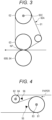
- Fig. 3 is a diagram schematically showing the fixer 60.
- a fixing method is limited to a belt fixing method.
- the fixing method is not limited to the belt fixing method in the present invention.
- the upper fixer 60A includes a fixing belt 61 having an endless shape, a heating roller 62, and an upper pressure roller 63 (belt heating type), which are the fixing-surface-side members.
- the fixing belt 61 is stretched between the heating roller 62 and the upper pressure roller 63 under a predetermined tension.
- a main body of the fixing belt 61 includes polyimide (PI), for example.
- An outer peripheral surface of the main body is covered with heat-resistant silicone rubber and serves as an elastic layer.
- a surface layer of the fixing belt 61 is covered or coated with a tube of perfluoroalkoxy (PFA) that is heat-resistant resin.
- the fixing belt 61 comes into contact with the paper on which a toner image is formed, and heats and fixes the toner image on the paper in a predetermined temperature range.
- the heating roller 62 heats the fixing belt 61.
- the heating roller 62 incorporates the heating source 60C that is, for example, a halogen heater that heats the fixing belt 61.
- the heating roller 62 has a configuration in which an outer peripheral surface at a cylindrical core metal formed of aluminum or the like is covered with a resin layer coated with PTFE.
- Temperature of the heating source 60C is controlled by the controller 101.
- the heating roller 62 is heated by the heating source 60C, and as a result, the fixing belt 61 is heated. Thus, the toner formed on the paper is heated.
- the controller 101 controls toner fixing temperature by controlling the heating source 60C on the basis of, for example, an on/off pattern in a predetermined duty ratio in half-wave units.
- the upper pressure roller 63 is formed by covering, with an elastic layer, a solid core metal formed of metal such as iron, for example.
- a material of the elastic layer for example, heat-resistant silicone rubber can be used.
- the heat-resistant silicone rubber can be covered with a resin layer coated with PTFE that is heat-resistant low friction resin.
- the lower fixer 60B includes a lower pressure roller 64 that constitutes a back-surface-side support member (roller pressure method).
- the lower pressure roller 64 is formed by covering, with an elastic layer, an outer peripheral surface of a base material layer including aluminum (Al).
- Al aluminum
- heat-resistant silicone rubber can be used as a material of the elastic layer.
- the heat-resistant silicone rubber can be covered with a resin layer of a PFA tube as a surface release layer.
- a heating source such as a halogen heater may be incorporated in the lower pressure roller 64.
- the lower pressure roller 64 is heated by the heating source generating heat.
- the controller 101 may control toner fixing temperature by controlling the heating source on the basis of, for example, an on/off pattern in a predetermined duty ratio in half-wave units.
- the lower pressure roller 64 is pressed against the upper pressure roller 63 at a predetermined fixing load via the fixing belt 61. In this manner, a fixing nip NP that nips and conveys the paper is formed between the upper pressure roller 63 and the fixing belt 61, and the lower pressure roller 64.
- the lower pressure roller 64 is connected to a motor, a gear, or the like (not shown), and drive force of the motor is transmitted to the lower pressure roller 64.
- the controller 101 outputs a drive signal to the motor that drives the lower pressure roller 64 to control peripheral speed of the lower pressure roller 64.
- the upper fixer 60A, the lower fixer 60B, and the heating source 60C fix an unfixed toner image on the paper by conveying the paper while heating and pressurizing the paper with the fixing nip NP.
- the paper pre-heater 80 is disposed on an upstream side of the intermediate transfer unit 42 (hereinafter, simply referred to as "upstream side”) in the paper conveyance direction, and is disposed on a downstream side of the paper feeder 51 (hereinafter, simply referred to as "downstream side”) in the paper conveyance direction.
- upstream side an upstream side of the intermediate transfer unit 42
- downstream side a downstream side of the paper feeder 51
- Fig. 4 is an enlarged view showing an example of a configuration of the paper pre-heater 80 according to the present embodiment.
- the paper pre-heater 80 includes a front-surface-side roller 81 and a back-surface-side roller 82.
- the front-surface-side roller 81 is disposed on a downstream side of a back-surface-side roller 82.
- the front surface of the paper corresponds to an "image formation surface" in the present invention.
- the front-surface-side roller 81 is disposed so as to come into contact with the front surface of the paper.
- the front-surface-side roller 81 incorporates a front-surface-side heating source 83 (a halogen heater, for example) that heats the front-surface side of the paper.
- a diameter of the front-surface-side roller 81 is larger than a diameter of the back-surface-side roller 82.
- a front-surface-side roller temperature sensor 95 (described later) that detects temperature of the front-surface-side roller 81 is disposed in a vicinity of the front-surface-side roller 81.
- the back-surface-side roller 82 is disposed so as to come into contact with the back surface of the paper.
- the back-surface-side roller 82 incorporates a back-surface-side heating source 84 (a halogen heater, for example) that heats the back-surface side of the paper.
- the back-surface-side roller 82 is disposed at a position not facing the front-surface-side roller 81 with the paper interposed therebetween. Thus, a paper nip is not formed and the paper is not nipped. Therefore, deformation of the paper, such as a wrinkle is less likely to occur.
- a back-surface-side roller temperature sensor 96 (described later) that detects temperature of the back-surface-side roller 82 is disposed in a vicinity of the back-surface-side roller 82.
- the paper sent out from the paper feeder 51 is wound around the back-surface-side roller 82 in a counterclockwise direction. Then, the paper is passed from the back-surface-side roller 82 to the front-surface-side roller 81, and further wound around the front-surface-side roller 81 in a clockwise direction.
- a circumferential length L1 in which the front-surface-side roller 81 and the front surface of the paper come into contact with each other is a length from an eleven o'clock position to six o'clock position of the front-surface-side roller 81 in the clockwise direction.
- a circumferential length L2 in which the back-surface-side roller 82 and the back surface of the paper come into contact with each other is a length from a twelve o'clock position to five o'clock position of the back-surface-side roller 82 in the counterclockwise direction. Because the diameter of the front-surface-side roller 81 is larger than the diameter of the back-surface-side roller 82, the circumferential length L1 is equal to or greater than the circumferential length L2 (L1 ⁇ L2). Thus, the temperature of the back surface of the paper heated by the back-surface-side roller 82 can be set lower than the temperature of the front surface of the paper heated by the front-surface-side roller 81.
- Fig. 5 is a diagram showing paper temperature at each paper position immediately after image formation starts.
- Fig. 6 is a diagram showing the paper temperature at each paper position five minutes after the image formation starts.
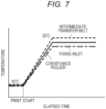
- Fig. 7 is a diagram showing a relationship between paper temperature and an elapsed time from the start of the image formation, for each position on a conveyance path.
- "paper feeding”, “paper pre-heater”, “conveyor”, “transferrer”, and “fixing inlet” shown in Figs. 5 and 6 indicate positions (paper positions) of the “paper feeder 51", "front-surface-side roller 81", “conveyance rollers 53a”, “intermediate transfer unit 42", and "inlet of the fixer 60", respectively.
- the machine and the paper are also cooled to 10°C. If image formation is started in this low-temperature environment, the temperature of the paper at the inlet of the fixer falls to 12°C even in a case where the paper temperature is raised to 25°C by the paper pre-heater 80, because the paper is cooled by the conveyance rollers 53a disposed between the paper pre-heater 80 and the intermediate transfer unit 42, and by the intermediate transfer belt 421 (refer to Fig. 5 ).
- fixing temperature the temperature of the fixing belt 61 (hereinafter, referred to as "fixing temperature") detected by a fixing-belt temperature sensor 93 (refer to Fig. 8 ) is equal to or lower than a predetermined temperature Tfs (15°C, for example). Then, in a case where the fixing temperature is equal to or lower than the predetermined temperature Tfs, paper pre-heating processing for heating the paper is performed at a time of warming up the fixer 60 (warm-up time).
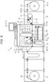
- Fig. 8 is a diagram showing an example of an arrangement configuration of temperature sensors according to the present embodiment.
- a paper pre-heater outlet paper temperature sensor 91, a fixer-inlet paper temperature sensor 92, the fixing-belt temperature sensor 93, an intermediate-transfer-belt temperature sensor 94, the front-surface-side roller temperature sensor 95, and the back-surface-side roller temperature sensor 96 are disposed at predetermined positions of the image formation apparatus 1.
- the paper pre-heater outlet paper temperature sensor 91 is a contactless temperature sensor, and detects the temperature of the front surface of the paper at an outlet of the paper pre-heater 80.
- the fixer-inlet paper temperature sensor 92 is a contactless temperature sensor, and detects the temperature of the front surface of the paper at the inlet of the fixer 60.
- the fixing-belt temperature sensor 93 detects the temperature of the fixing belt 61 (fixing temperature).
- the intermediate-transfer-belt temperature sensor 94 detects temperature of the intermediate transfer belt 421.
- the front-surface-side roller temperature sensor 95 detects the temperature of the front-surface-side roller 81.
- the back-surface-side roller temperature sensor 96 detects the temperature of the back-surface-side roller 82.
- the controller 101 acquires respective detection results from the paper pre-heater outlet paper temperature sensor 91, the fixer-inlet paper temperature sensor 92, the fixing-belt temperature sensor 93, the intermediate-transfer-belt temperature sensor 94, the front-surface-side roller temperature sensor 95, and the back-surface-side roller temperature sensor 96.
- the controller 101 executes paper pre-heating control and warm-up control for the fixer 60 in parallel.
- the paper pre-heating control includes (1) transfer press control, (2) control of the paper conveyor 50, and (3) lighting control for each of the front-surface-side heating source 83 and the back-surface-side heating source 84.
- the warm-up control for the fixer 60 includes (4) drive speed control for the upper pressure roller 63 and the lower pressure roller 64, and (5) lighting control for the heating source 60C.
- the controller 101 executes transfer press control.
- the secondary transfer roller 424 is pressed against the backup roller 423B with the intermediate transfer belt 421 interposed therebetween.
- the paper conveyed from the paper feeder 51 via the conveyance rollers 53a can be brought into contact with the intermediate transfer belt 421 and the secondary transfer roller 424.
- the controller 101 controls the paper conveyor 50 so that a paper conveyance speed at a time of paper pre-heating is a predetermined speed WVph.
- a paper conveyance speed at a time of paper pre-heating is a predetermined speed WVph.
- the predetermined speed WVph at the time of paper pre-heating is set to a speed lower than a paper conveyance speed VP at a time of the image formation.
- the paper is conveyed at a low speed. Therefore, waste paper can be reduced, and the paper can be efficiently heated.
- the controller 101 controls the paper conveyor 50 to stop conveyance of the paper.
- the intermediate transfer belt 421, the secondary transfer roller 424, and the conveyance rollers 53a which come in contact with the paper on the upstream side of the fixer 60, are sufficiently warmed. As a result, it is possible to reduce a chance of a decrease in the paper temperature immediately after the start of the image formation switched from warm-up (paper pre-heating).
- the controller 101 performs lighting control for the front-surface-side heating source 83 so that the temperature of the front-surface-side roller 81 is at a predetermined temperature WTph1, and performs lighting control for the back-surface-side heating source 84 so that the temperature of the back-surface-side roller 82 is at a predetermined temperature WTph2.
- the predetermined temperature WTph1 is set to a temperature higher than the predetermined temperature WTph2.
- the temperature of the back surface of the paper can be set lower than the temperature of the front surface of the paper.
- the paper conveyed from the paper pre-heater 80 via the conveyance rollers 53a warms the conveyance rollers 53a and the intermediate transfer belt 421. However, if the temperature of the intermediate transfer belt 421 is too high, cleaned toner is welded.
- the controller 101 performs lighting control for the front-surface-side heating source 83 and the back-surface-side heating source 84 so that temperature of the intermediate transfer belt 421 detected by the intermediate-transfer-belt temperature sensor 94 does not exceed a predetermined temperature Tbs. Thus, it is possible to reduce a chance of welded toner.
- the controller 101 turns off lighting of the front-surface-side heating source 83 and the back-surface-side heating source 84.
- the controller 101 performs control so that drive speeds of the upper pressure roller 63 and the lower pressure roller 64 are at a predetermined speed WVf.
- the controller 101 performs lighting control for the heating source 60C so that the fixing temperature is at a predetermined temperature WTf.
- the controller 101 determines whether or not an elapsed time from the start of the warm-up control for the fixer 60 (warm-up time) is equal to or longer than a predetermined time TMw.
- the controller 101 ends the warm-up control for the fixer 60.
- the fixing temperature is set to a predetermined temperature PTf.
- the controller 101 executes the paper pre-heating control and the warm-up control for the fixer 60 in parallel. Thereafter, the controller 101 executes image formation control.
- Fig. 9 is a flowchart showing an example of operation of the image formation apparatus 1 according to the present embodiment. This flow is started by an image formation instruction input to the image formation apparatus 1.
- the temperature of the front-surface-side roller 81 is shown as "pre-heating front”.
- the temperature of the back-surface-side roller 82 is shown as "pre-heating back”.
- step S100 the controller 101 determines whether or not the fixing temperature is equal to or lower than the predetermined temperature Tfs (15°C, for example).
- step S100 the fixing temperature is equal to or lower than the predetermined temperature Tfs (step S100: YES)
- the paper pre-heating control steps S110 to S160
- the warm-up control for the fixer 60 steps S200 to S240
- step S110 the controller 101 executes transfer press control.
- the paper can be brought into contact with the intermediate transfer belt 421 and the secondary transfer roller 424.
- step S120 the controller 101 controls the paper conveyor 50 so that the paper conveyance speed is at the predetermined speed WVph.
- step S130 the controller 101 controls the front-surface-side heating source 83 so that the temperature of the front-surface-side roller 81 is at the predetermined temperature WTph1, and controls the back-surface-side heating source 84 so that the temperature of the back-surface-side roller 82 is at the predetermined temperature WTph2.
- step S140 the controller 101 determines whether or not the paper temperature at the inlet of the fixer 60 (fixer-inlet paper temperature shown in Fig. 9 ) is equal to or higher than the predetermined temperature WTpa2. In a case where the paper temperature is equal to or higher than the predetermined temperature WTpa2 (step S140: YES), the processing proceeds to step S150. In a case where the paper temperature is lower than the predetermined temperature WTpa2 (step S140: NO), the processing returns to step before step S130.
- step S150 the controller 101 turns off the front-surface-side heating source 83 and the back-surface-side heating source 84.
- step S160 the controller 101 controls the paper conveyor 50 so that the conveyance of the paper is stopped. Thereafter, the image formation is started. At the time of the image formation, a conveyance speed in paper pre-heating is controlled to the same conveyance speed as a conveyance speed in the image formation.
- the front-surface-side heating source 83 and the back-surface-side heating source 84 are controlled so that the temperatures of the front-surface-side roller 81 and back-surface-side roller 82 are set to PTph1 and PTph2, respectively.
- the controller 101 executes the following control in parallel with the above paper pre-heating control (steps S110 to S160).
- step S200 the controller 101 performs control so that drive speeds of the upper pressure roller 63 and the lower pressure roller 64 are at the predetermined speed WVf.
- step S210 the controller 101 performs lighting control for the heating source 60C so that the fixing temperature is at a predetermined temperature WTf.
- step S220 the controller 101 determines whether or not the fixing temperature is equal to or higher than the predetermined temperature WTf. In a case where the fixing temperature is equal to or higher than the predetermined temperature WTf (step S220: YES), the processing proceeds to step S230. In a case where the fixing temperature is lower than the predetermined temperature WTf (step S220: NO), the processing returns to step before step S210.
- step S230 the controller 101 determines whether or not an elapsed time from start of the warm-up (warm-up time) is equal to or longer than the predetermined time TMw. In a case where the warm-up time is equal to or longer than the predetermined time TMw (step S230: YES), the processing proceeds to step S240. In a case where the warm-up time is shorter than the predetermined time TMw (step S230: NO), the processing returns to step before step S210.
- step S240 the fixing temperature is set to the predetermined temperature PTf. Thereafter, if the paper pre-heating is at step S160, the image formation is started. If the paper pre-heating has not yet reached step S100, the image formation is started after step S160 is reached.
- the image formation apparatus 1 includes the intermediate transfer unit 42 that forms the toner image on the front surface of the paper, the fixer 60 that fixes the toner image onto the paper, the paper conveyor 50 that conveys the paper between an upstream side of the intermediate transfer unit 42 and a downstream side of the fixer 60 in the paper conveyance direction, and the paper pre-heater 80 that heats the front-surface side of the paper on the upstream side of the intermediate transfer unit 42 in the paper conveyance direction.
- the front-surface-side roller 81 comes into contact with the front surface of the paper on the upstream side of the intermediate transfer unit 42, and the temperature of the front surface of the paper sufficiently rises. Therefore, it is possible to reduce occurrence of fixing under offset and image unevenness.
- the front-surface-side roller 81 and the back-surface-side roller 82 come into contact with the paper on the upstream side of the intermediate transfer unit 42, it is possible to reduce a chance of disturbance of an unfixed toner image.
- the paper pre-heater 80 heats the front-surface side of the paper at time of warm-up of the fixer.
- a paper conveyance speed at the time of warm-up is lower than a paper conveyance speed at the time of the image formation in which the toner image is formed on the front surface of the paper.
- the diameter of the front-surface-side roller 81 is larger than the diameter of the back-surface-side roller 82.
- the circumferential length L1 in which the front-surface-side roller 81 is in contact with the front surface of the paper is equal to or longer than the circumferential length L2 in which the back-surface-side roller 82 is in contact with the back surface of the paper.
- the temperature of the back surface of the paper heated by the back-surface-side roller 82 can be set lower than the temperature of the front surface of the paper heated by the front-surface-side roller 81.
- the temperature on the back-surface side of the paper can remain low. Therefore, the paper can be efficiently heated while reducing a chance of toner blister or paper blister.
- the paper pre-heater 80 includes the front-surface-side roller 81 disposed so as to come into contact with the front surface of the paper, and the back-surface-side roller 82 disposed, at a position not facing the front-surface-side roller 81 with the paper interposed therebetween so as to come into contact with the back surface of the paper.
- the paper is not sandwiched between the front-surface-side roller 81 and the back-surface-side roller 82. Therefore, it is possible to reduce a chance of deformation of the paper, such as a wrinkle.
- an amount the paper pre-heater 80 heats the front-surface side of the paper is equal to or larger than an amount the paper pre-heater 80 heats the back-surface side of the paper.
- the front-surface side of the paper can be efficiently heated.
- the temperature on the back-surface side does not rise excessively. Therefore, it is possible to reduce a chance of toner blister or paper blister.
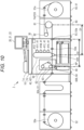
- Fig. 10 is a diagram showing a predetermined distance of repeatedly conveyed paper in the image formation apparatus 1 according to a first modification, at the time of the paper pre-heating.
- the paper conveyance speed at the time of the warm-up (at the time of the paper pre-heating executed in parallel) is set slower than the paper conveyance speed at the time of the image formation.
- the first modification in order to shorten the length of the waste paper, the paper is repeatedly conveyed at the time of the paper pre-heating.
- the paper conveyor 50 conveys the paper, which is continuous paper, in a reciprocating manner for the predetermined distance or longer at the time of paper pre-heating.
- the fixer also heats the paper. With this arrangement, the length of the waste paper can be further shortened.
- the predetermined distance of the conveyance in the reciprocating manner is determined by a positional relationship among the paper pre-heater, the fixer, an intermediate transferrer, and the conveyor.
- the predetermined distance is set as follows. First, a distance D1 between the front-surface-side roller 81 and the intermediate transfer unit 42 is compared with a distance D2 between the fixer 60 and a conveyance roller 53a on an uppermost stream.
- the "the conveyance roller on the uppermost stream” refers to a conveyance roller positioned on an uppermost stream side, among a plurality of conveyance rollers disposed between the fixer 60 and the front-surface-side roller 81.
- the predetermined distance is set to the shorter distance D2 (D1 ⁇ D2)
- the paper heated by the front-surface-side roller 81 does not reach the intermediate transfer unit 42. Therefore, the intermediate transfer unit 42 is not warmed by the paper heated by the front-surface-side roller 81. Meanwhile, the paper heated by the fixer 60 is warmed. If the predetermined distance is set to the longer distance D1 or longer, the paper heated by the front-surface-side roller 81 reaches the intermediate transfer unit 42. Therefore, the intermediate transfer unit 42 is warmed by the paper heated by the front-surface-side roller 81. The paper is also warmed by the paper heated by the fixer 60.
- the intermediate transfer unit 42 and the conveyance rollers 53a can be more efficiently warmed, the length of the waste paper can be shortened, and the paper pre-heating time at the time of warm-up can be shortened. Then, even if an image is formed in a state where the machine or the paper is left at a low temperature, the paper is conveyed to the fixer 60 without the temperature of the paper falling at the intermediate transfer unit 42. Therefore, it is possible to reduce occurrence of fixing under offset.
- the predetermined distance is set to the shorter distance D1
- the paper heated by the front-surface-side roller 81 reaches the intermediate transfer unit 42.
- the paper heated by the fixer 60 does not reach the intermediate transfer unit 42 or a conveyance roller 53a. If the predetermined distance is set to the longer distance D2 or longer, the intermediate transfer unit 42 and the conveyance rollers 53a are warmed by the paper heated by both the front-surface-side roller 81 and the fixer 60.
- the fixer 60 in a case where the paper pre-heating is executed at the time of warm-up, the fixer 60 does not heat the front-surface side of the paper. Meanwhile, in the first modification, the front-surface side of the paper is heated. Specifically, the fixer 60 presses the paper at the time of the warm-up, and heats and conveys the paper with the fixing nip NP. Thus, the paper is heated by both the paper pre-heater 80 and the fixer 60. Therefore, it is possible to warm the intermediate transfer unit 42 and the conveyance rollers 53a more efficiently. Note that the fixer 60 heats the paper at a reciprocation cycle the same as a reciprocation cycle of the paper pre-heater 80.
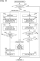
- Fig. 11 is a flowchart showing an example of operation of the image formation apparatus 1 according to the first modification.
- the temperature of the front-surface-side roller 81 is shown as "pre-heating front”.
- the temperature of the back-surface-side roller 82 is shown as "pre-heating back”.
- the paper pre-heating control and the warm-up control for the fixer 60 are executed in parallel.
- steps that are the same as the steps shown in Fig. 9 will be omitted, and different steps will be mainly described.
- step S120 shown in Fig. 9 the controller 101 controls the paper conveyor 50 so that the paper conveyance speed is at the predetermined speed WVph.
- step S320 shown in Fig. 11 the controller 101 controls the paper conveyor 50 so that the paper conveyance speed is at the predetermined speed WVph and that the paper is conveyed in the reciprocating manner (repeatedly conveyed) at a predetermined reciprocation cycle LR.
- step S140 shown in Fig. 9 the controller 101 determines whether or not the fixer-inlet paper temperature is equal to or higher than the predetermined temperature WTpa2. Meanwhile, in step S340 shown in Fig. 11 , the controller 101 determines whether or not the temperature of the intermediate transfer belt 421 (transfer belt temperature shown in Fig. 11 ) is equal to or higher than a predetermined temperature WTb.
- the controller 101 controls the fixer 60 so as to convey (fix-press) the paper while heating and pressurizing the paper with the fixing nip NP.
- step S200 shown in Fig. 9 the controller 101 performs control so that the drive speeds of the upper pressure roller 63 and the lower pressure roller 64 are at the predetermined speed WVf.
- step S380 shown in Fig. 11 control is performed so that the drive speeds of the upper pressure roller 63 and the lower pressure roller 64 are at the predetermined speed WVf, and that the upper pressure roller 63 and the lower pressure roller 64 are driven in a reciprocating manner at the predetermined reciprocation cycle LR.
- step S340 of the paper pre-heating control that the temperature of the intermediate transfer belt 421 (the transfer belt temperature shown in Fig.
- the controller 101 performs control so as to switch from the drive in the reciprocating manner as described above to normal drive (drive in a conveyance direction), and so as to release the fixing.
- the paper repeatedly conveyed at the time of paper pre-heating is continuous paper.
- the paper is not limited thereto and is cut paper.
- the paper conveyor 50 may also function as, for example, a circulatory conveyance path of the image formation apparatus 1.
- the circulatory conveyance path is capable of forming images on both surfaces of the paper while circulating and conveying the paper.
- the circulatory conveyance path circulates and conveys the paper by returning the paper, which is conveyed from the paper pre-heater 80 to a downstream side of the fixer 60, to an upstream side of the paper pre-heater 80.
- the intermediate transfer unit 42 and the conveyance rollers 53a are disposed between the downstream side of the paper feeder 51 and an upstream side of the paper ejector 52.
- the paper conveyor 50 repeatedly conveys a predetermined number of sheets of the paper, which is the cut paper, at the time of the paper pre-heating.
- the intermediate transfer unit 42 and the conveyance rollers 53a are warmed by the paper.
- the paper is conveyed to the fixer 60 without the temperature of the paper falling at the intermediate transfer unit 42 or the conveyance rollers 53a. Therefore, it is possible to reduce occurrence of fixing under offset.
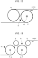
- Fig. 12 is an enlarged view showing an example of a configuration of the paper pre-heater 80 according to the third modification.
- the front-surface-side roller 81 incorporates the front-surface-side heating source 83.
- the back-surface-side roller 82 incorporates the back-surface-side heating source 84. Because the diameter of the front-surface-side roller 81 is larger than the diameter of the back-surface-side roller 82, the circumferential length L1 in which the front-surface-side roller 81 and the front surface of the paper come into contact with each other is equal to or greater than the circumferential length L2 in which the back-surface-side roller 82 and the back surface of the paper come into contact with each other (L1 ⁇ L2).
- the front-surface-side roller 81 incorporates the front-surface-side heating source 83, but the back-surface-side roller 82 does not incorporate the back-surface-side heating source 84.
- the diameter of the front-surface-side roller 81 is the same as the diameter of the back-surface-side roller 82.
- Fig. 13 is an enlarged view showing an example of a configuration of the paper pre-heater 80 according to the fourth modification.
- one front-surface-side roller 81 heats the front-surface side of the paper.
- a plurality of front-surface-side rollers 81 heats the front-surface side of the paper.
- Each of the plurality of front-surface-side rollers 81 incorporates the front-surface-side heating source 83.
- the plurality of front-surface-side rollers 81 can efficiently heat the front-surface side of the paper.
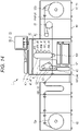
- Fig. 14 is a diagram schematically showing the image formation apparatus 1 according to the fifth modification.
- the paper conveyor 50 includes a plurality of conveyance rollers 53a disposed between the paper pre-heater 80 and the intermediate transfer unit 42 so as to come into contact with the paper.
- the paper conveyor 50 is disposed between the paper pre-heater 80 and the intermediate transfer unit 42 so as not to come into contact with the paper. Specifically, the conveyance rollers 53a to be in contact with the paper are not disposed between the paper pre-heater 80 and the intermediate transfer unit 42. Thus, it possible to reduce a decrease in temperature of the paper heated by the paper pre-heater 80 and conveyed from the paper pre-heater 80 to the intermediate transfer unit 42.
- the paper pre-heater 80 may heat the paper without being brought into contact with the paper.
- an infrared heater or the like is used as the paper pre-heater 80.
- the present invention is suitably used for an image formation apparatus that is required to reduce occurrence of image formation failure.
Landscapes
- Physics & Mathematics (AREA)
- General Physics & Mathematics (AREA)
- Fixing For Electrophotography (AREA)
- Paper Feeding For Electrophotography (AREA)
- Control Or Security For Electrophotography (AREA)
Abstract
Description
- The present invention relates to an image formation apparatus and an image formation method.
- When paper is cooled in a low temperature environment, toner is difficult to fuse onto the paper, and temperature of a fixing member falls. Therefore, fixing under offset (low-temperature fixing) occurs. To deal with this problem, the paper is heated before the toner is fixed to raise temperature of the paper.
- For example,
JP 2017-156516 A - In
JP 2017-156516 A - If, between the transferrer and the fixer, the paper pre-heating member is brought into contact with the paper, disturbance of an unfixed toner image occurs. In particular, if the paper pre-heating member that slides on paper is used, toner is more easily scattered. Therefore, there has been a problem that disturbance of an unfixed toner image may occur.
- An object of the present invention is to provide an image formation apparatus and image formation method capable of reducing occurrence of image formation failure.
- To achieve the abovementioned object, according to an aspect of the present invention, an image formation apparatus reflecting one aspect of the present invention comprises
- a transferrer that forms a toner image on an image formation surface of paper;
- a fixer that fixes the toner image on the paper;
- a paper conveyor that conveys the paper between an upstream side of the transferrer and a downstream side of the fixer in a paper conveyance direction; and
- a paper pre-heater that heats, on the upstream side of the transferrer in the paper conveyance direction, the image formation surface of the paper.
- The advantages and features provided by one or more embodiments of the invention will become more fully understood from the detailed description given hereinbelow and the appended drawings which are given by way of illustration only, and thus are not intended as a definition of the limits of the present invention:
-
Fig. 1 is a diagram schematically showing an overall configuration of an image formation apparatus according to an embodiment of the present invention; -
Fig. 2 is a diagram showing main units of a control system of the image formation apparatus according to the present embodiment; -
Fig. 3 is a diagram schematically showing a configuration of a fixer; -
Fig. 4 is an enlarged view showing an example of a configuration of a paper pre-heater according to the present embodiment; -
Fig. 5 is a diagram showing paper temperature at each paper position immediately after image formation starts; -
Fig. 6 is a diagram showing the paper temperature at each paper position five minutes after the image formation starts; -
Fig. 7 is a diagram showing a relationship between paper temperature and an elapsed time from the start of the image formation, for each position on a conveyance path; -
Fig. 8 is a diagram showing an example of an arrangement configuration of temperature sensors; -
Fig. 9 is a flowchart showing an example of operation of the image formation apparatus according to the present embodiment; -
Fig. 10 is a diagram showing a predetermined distance of repeatedly conveyed paper in the image formation apparatus according to a first modification, at a time of paper pre-heating; -
Fig. 11 is a flowchart showing an example of operation of the image formation apparatus according to the first modification; -
Fig. 12 is an enlarged view showing an example of a configuration of the paper pre-heater according to a third modification; -
Fig. 13 is an enlarged view showing an example of a configuration of the paper pre-heater according to a fourth modification; and -
Fig. 14 is a diagram schematically showing an overall configuration of the image formation apparatus according to a fifth modification. - Hereinafter, one or more embodiments of the present invention will be described with reference to the drawings. However, the scope of the invention is not limited to the disclosed embodiments.
Fig. 1 is a diagram schematically showing an overall configuration of animage formation apparatus 1 according to an embodiment of the present invention.Fig. 2 is a diagram showing main units of a control system of theimage formation apparatus 1 according to the present embodiment. Theimage formation apparatus 1 is an intermediate transfer type color image formation apparatus utilizing electrophotographic process technology. That is, theimage formation apparatus 1 primarily transfers toner images of colors of yellow (Y), magenta (M), cyan (C), and black (K), which are formed onrespective photoreceptor drums 413, onto an intermediate transfer belt 421, superimposes the toner images of the four colors on the intermediate transfer belt 421, and then secondarily transfers the superimposed toner images onto paper, thereby forming a toner image. - In addition, the
image formation apparatus 1 adopts a tandem system in which thephotoreceptor drums 413 corresponding to the four colors of YMCK are arranged in series in a running direction of the intermediate transfer belt 421, and the toner images of the respective colors are sequentially transferred onto the intermediate transfer belt 421 with one procedure. - As shown in
Fig. 2 , theimage formation apparatus 1 includes animage reader 10, anoperation display 20, animage processor 30, an image former 40, apaper conveyor 50, afixer 60, a paper pre-heater 80, acontroller 101, and the like. - The
controller 101 includes a central processing unit (CPU) 102, a read only memory (ROM) 103, a random access memory (RAM) 104, and the like. TheCPU 102 reads, from theROM 103, a program corresponding to processing content, loads the program into theRAM 104, and centrally controls operation of each block of theimage formation apparatus 1 in cooperation with the loaded program. At this time, various data stored in astorage 72 are referred to. Thestorage 72 includes, for example, a non-volatile semiconductor memory (so-called flash memory) or a hard disk drive. - Via a
communicator 71, thecontroller 101 transmits and receives various data to and from an external apparatus (for example, a personal computer) connected to a communication network such as a local area network (LAN) or a wide area network (WAN). For example, thecontroller 101 receives image data transmitted from the external apparatus, and forms a toner image on the paper on the basis of the image data (input image data). Thecommunicator 71 includes, for example, a communication control card such as a LAN card. - The
image reader 10 includes an automatic document feeder 11, which is referred to as an auto document feeder (ADF), a document image scanner (scanner) 12, and the like. - With a conveyance mechanism, the automatic document feeder 11 conveys a document placed on a document tray, and sends the document to the
document image scanner 12. The automatic document feeder 11 can continuously read images (including both sides) of a large number of documents placed on the document tray at once. - The document image scanner 12 optically scans a document conveyed onto a contact glass from the automatic document feeder 11, or a document placed on the contact glass, forms, on a light receiving surface of a charge coupled device (CCD) sensor (not shown), an image of light reflected from the document, and reads a document image. The
image reader 10 generates input image data on the basis of a result of reading by thedocument image scanner 12. The input image data is subjected to predetermined image processing in theimage processor 30. - The
operation display 20 includes, for example, a liquid crystal display (LCD) with a touch panel, and functions as adisplay 21 and anoperation unit 22. Thedisplay 21 displays various operation screens, an image state, an operation status of each function, and the like according to a display control signal input from thecontroller 101. Theoperation unit 22 includes various operation keys such as a numeric keypad and a start key, receives various input operations by a user, and outputs an operation signal to thecontroller 101. The input operations includes operation of selecting any one of a normal mode, a low-gloss mode in which a gloss level is lower than a predetermined value (value of the normal mode), and a high-gloss mode in which the gloss level is higher than the predetermined value. - The
image processor 30 includes a circuit or the like that performs digital image processing on the input image data according to an initial setting or user setting. For example, theimage processor 30 performs gradation correction on the basis of gradation correction data (gradation correction table) under control of thecontroller 101. In addition to the gradation correction, on the input image data, theimage processor 30 performs various kinds of correction processing such as color correction and shading correction, compression processing, and the like. The image former 40 is controlled on the basis of the image data subjected to these processings. - The image former 40 includes
image formation units image formation units - The
image formation units Fig. 1 , only a constituent of theimage formation unit 41Y for the Y component is denoted by a reference sign, and reference signs for constituents of the otherimage formation units - An
image formation unit 41 includes an exposurer (not shown), a developer (not shown), aphotoreceptor drum 413, an electric charger (not shown), a drum cleaner (not shown), and the like. - The
photoreceptor drum 413 is, for example, a negatively charged organic photo-conductor (OPC) in which an under coat layer (UCL), a charge generation layer (CGL), and a charge transport layer (CTL) are sequentially laminated on a peripheral surface of an aluminum conductive cylindrical body (aluminum tube). The charge generation layer includes an organic semiconductor obtained by dispersing a charge generation material (polycarbonate, for example) in a resin binder (for example, polycarbonate), and generates a pair of positive charge and negative charge with exposure by the exposurer. The charge transport layer is formed by a resin binder (polycarbonate resin, for example) in which a hole-transport material (electron-donating nitrogen-containing compound) is dispersed, and transports a positive charge generated in the charge generation layer to a surface of the charge transport layer. - The
controller 101 rotates the photoreceptor drums 413 at a constant peripheral speed by controlling drive current supplied to a drive motor (not shown) that rotates the photoreceptor drums 413. - The electric charger uniformly charges a surface of the
photoreceptor drum 413 having photoconductivity to negative polarity. The exposurer includes, for example, a semiconductor laser, and irradiates thephotoreceptor drum 413 with laser light corresponding to an image of each color component. The positive charge is generated in the charge generation layer of thephotoreceptor drum 413 and is transported to the surface of the charge transport layer, by which a surface charge (negative charge) of thephotoreceptor drum 413 is neutralized. An electrostatic latent image of each color component is formed on the surface of thephotoreceptor drum 413 due to a potential difference from surroundings. - The developer is, for example, a two-component developer, and visualizes the electrostatic latent image by attaching the toner of each color component to the surface of the
photoreceptor drum 413 to form a toner image. - The drum cleaner includes a drum cleaning blade or the like that comes into sliding contact with the surface of the
photoreceptor drum 413, and, after the primary transfer, removes transfer residual toner remaining on the surface of thephotoreceptor drum 413. - The intermediate transfer unit 42 includes the intermediate transfer belt 421, a primary transfer roller (not shown), a plurality of support rollers (not shown), a
secondary transfer roller 424, a belt cleaner (not shown), and the like. - The intermediate transfer belt 421 is formed by an endless belt, and is stretched in a loop shape around the plurality of support rollers. At least one of the plurality of support rollers includes a drive roller, and the other support rollers include a driven roller. For example, the drive roller is preferably a roller disposed on a downstream side of the primary transfer roller for the K component in a belt running direction. Thus, running speed of the belt in a primary transferrer can be easily kept constant. As the drive roller rotates, the intermediate transfer belt 421 runs at a constant speed in a direction of the arrow A.
- The primary transfer roller is disposed on an inner peripheral surface side of the intermediate transfer belt 421 so as to face the photoreceptor drums 413 of the respective color components. Primary transfer nips for transferring the toner images from the photoreceptor drums 413 to the intermediate transfer belt 421 are formed by the primary transfer rollers being pressed against the
respective photoreceptor drums 413 with the intermediate transfer belt 421 interposed therebetween. - The
secondary transfer roller 424 is disposed on an outer peripheral surface side of the intermediate transfer belt 421 while facing a backup roller 423B disposed on the downstream side of the drive roller in the belt running direction. A secondary transfer nip for transferring the toner images from the intermediate transfer belt 421 onto the paper is formed by thesecondary transfer roller 424 being pressed against a backup roller (not shown) with the intermediate transfer belt 421 interposed therebetween. - When the intermediate transfer belt 421 passes through the primary transfer nips, the toner images on the photoreceptor drums 413 are sequentially superimposed and primarily transferred onto the intermediate transfer belt 421. Specifically, primary transfer bias is applied to the primary transfer rollers, and charge with polarity opposite to polarity of the toner is applied to a back-surface side of the intermediate transfer belt 421 (side in contact with the primary transfer roller), by which the toner images are electrostatically transferred onto the intermediate transfer belt 421.
- Thereafter, when the paper passes through the secondary transfer nip, the toner images on the intermediate transfer belt 421 are secondarily transferred onto the paper. Specifically, secondary transfer bias is applied to the
secondary transfer roller 424, and charge with polarity opposite to polarity of the toner is applied to a back-surface side of the paper (side in contact with the secondary transfer roller 424), by which the toner images are electrostatically transferred onto the paper. The paper onto which the toner images have been transferred is conveyed toward thefixer 60. - The belt cleaner (not shown) includes a belt cleaning blade or the like that comes into sliding contact with a surface of the intermediate transfer belt 421, and, after the secondary transfer, removes transfer residual toner remaining on the surface of the intermediate transfer belt 421. Note that, instead of the
secondary transfer roller 424, a secondary transfer belt may be adopted by being stretched in a loop shape around the plurality of support rollers including a secondary transfer roller (so-called belt-type secondary transfer unit). - The
fixer 60 includes anupper fixer 60A having fixing-surface-side members disposed on a fixing surface (front surface on which the toner images are formed) side of the paper, alower fixer 60B having a back-surface-side support member disposed on a back surface (surface opposite to the fixing surface) side of the paper, aheating source 60C, and the like. When the back-surface-side support member is pressed against a fixing-surface-side member, a fixing nip that nips and conveys the paper is formed. - After the toner images are secondarily transferred onto the paper, the
fixer 60 fixes the toner images on the conveyed paper by heating and pressurizing the paper with the fixing nip. Thefixer 60 is disposed as a unit in a fixing device, that is, a housing. - The
paper conveyor 50 includes a paper feeder 51, apaper ejector 52, a conveyance path unit 53, and the like. The paper feeder 51 includes adelivery roller 51a that delivers, to a downstream side, the paper (continuous paper) wound in a roll. - The paper delivered to the downstream side of the paper feeder 51 is conveyed to the image former 40 by the conveyance path unit 53 via the paper pre-heater 80 (described later). In the image former 40, the toner images on the intermediate transfer belt 421 are secondarily transferred collectively onto one surface of the paper, and a fixing process is performed in the
fixer 60. Thepaper ejector 52 includes a windingroller 52a that winds, into a roll, the paper on which an image is formed. The conveyance path unit 53 includesconveyance rollers 53a that hold and convey paper. Note that the conveyance path unit 53 may include a paper tension application roller (not shown) that applies tension to the paper and a skew adjustment roller (not shown) that adjusts skew of the paper. - Next, a configuration of the
fixer 60 will be described in more detail with reference toFig. 3. Fig. 3 is a diagram schematically showing thefixer 60. In the present embodiment, a fixing method is limited to a belt fixing method. However, the fixing method is not limited to the belt fixing method in the present invention. - The
upper fixer 60A includes a fixingbelt 61 having an endless shape, aheating roller 62, and an upper pressure roller 63 (belt heating type), which are the fixing-surface-side members. The fixingbelt 61 is stretched between theheating roller 62 and theupper pressure roller 63 under a predetermined tension. - A main body of the fixing
belt 61 includes polyimide (PI), for example. An outer peripheral surface of the main body is covered with heat-resistant silicone rubber and serves as an elastic layer. Further, a surface layer of the fixingbelt 61 is covered or coated with a tube of perfluoroalkoxy (PFA) that is heat-resistant resin. - The fixing
belt 61 comes into contact with the paper on which a toner image is formed, and heats and fixes the toner image on the paper in a predetermined temperature range. - The
heating roller 62 heats the fixingbelt 61. Theheating roller 62 incorporates theheating source 60C that is, for example, a halogen heater that heats the fixingbelt 61. Theheating roller 62 has a configuration in which an outer peripheral surface at a cylindrical core metal formed of aluminum or the like is covered with a resin layer coated with PTFE. - Temperature of the
heating source 60C is controlled by thecontroller 101. Theheating roller 62 is heated by theheating source 60C, and as a result, the fixingbelt 61 is heated. Thus, the toner formed on the paper is heated. Thecontroller 101 controls toner fixing temperature by controlling theheating source 60C on the basis of, for example, an on/off pattern in a predetermined duty ratio in half-wave units. - The
upper pressure roller 63 is formed by covering, with an elastic layer, a solid core metal formed of metal such as iron, for example. As a material of the elastic layer, for example, heat-resistant silicone rubber can be used. In addition, as the elastic layer, the heat-resistant silicone rubber can be covered with a resin layer coated with PTFE that is heat-resistant low friction resin. - The
lower fixer 60B includes alower pressure roller 64 that constitutes a back-surface-side support member (roller pressure method). Thelower pressure roller 64 is formed by covering, with an elastic layer, an outer peripheral surface of a base material layer including aluminum (Al). As a material of the elastic layer, for example, heat-resistant silicone rubber can be used. In addition, as the elastic layer, the heat-resistant silicone rubber can be covered with a resin layer of a PFA tube as a surface release layer. - A heating source such as a halogen heater may be incorporated in the
lower pressure roller 64. Thelower pressure roller 64 is heated by the heating source generating heat. Thus, the toner formed on the paper is heated. Thecontroller 101 may control toner fixing temperature by controlling the heating source on the basis of, for example, an on/off pattern in a predetermined duty ratio in half-wave units. - The
lower pressure roller 64 is pressed against theupper pressure roller 63 at a predetermined fixing load via the fixingbelt 61. In this manner, a fixing nip NP that nips and conveys the paper is formed between theupper pressure roller 63 and the fixingbelt 61, and thelower pressure roller 64. - The
lower pressure roller 64 is connected to a motor, a gear, or the like (not shown), and drive force of the motor is transmitted to thelower pressure roller 64. Thecontroller 101 outputs a drive signal to the motor that drives thelower pressure roller 64 to control peripheral speed of thelower pressure roller 64. - In the
fixer 60, theupper fixer 60A, thelower fixer 60B, and theheating source 60C fix an unfixed toner image on the paper by conveying the paper while heating and pressurizing the paper with the fixing nip NP. - Meanwhile, in a case where the paper is thick paper, tack paper, or the like for example, temperature of the front surface of the paper does not sufficiently rise, and fixing under offset may occur, even if, between the intermediate transfer unit 42 and the
fixer 60, to heat the paper, the paper pre-heating member is brought into contact with the back surface of the paper. If an amount of heating from the back-surface side is increased so that fixing under offset does not occur, image unevenness due to toner blister may occur at a time of the fixing, or paper blister may occur. If, between the intermediate transfer unit 42 and thefixer 60, the paper pre-heating member is brought into contact with the paper, disturbance of an unfixed toner image may occur. - In the present embodiment, in order to reduce occurrence of image formation failure such as fixing under offset, image unevenness, disturbance of an unfixed toner image, or the like, the
paper pre-heater 80 is disposed on an upstream side of the intermediate transfer unit 42 (hereinafter, simply referred to as "upstream side") in the paper conveyance direction, and is disposed on a downstream side of the paper feeder 51 (hereinafter, simply referred to as "downstream side") in the paper conveyance direction. -
Fig. 4 is an enlarged view showing an example of a configuration of thepaper pre-heater 80 according to the present embodiment. As shown inFig. 4 , thepaper pre-heater 80 includes a front-surface-side roller 81 and a back-surface-side roller 82. The front-surface-side roller 81 is disposed on a downstream side of a back-surface-side roller 82. Here, the front surface of the paper corresponds to an "image formation surface" in the present invention. - The front-surface-
side roller 81 is disposed so as to come into contact with the front surface of the paper. The front-surface-side roller 81 incorporates a front-surface-side heating source 83 (a halogen heater, for example) that heats the front-surface side of the paper. A diameter of the front-surface-side roller 81 is larger than a diameter of the back-surface-side roller 82. A front-surface-side roller temperature sensor 95 (described later) that detects temperature of the front-surface-side roller 81 is disposed in a vicinity of the front-surface-side roller 81. - The back-surface-
side roller 82 is disposed so as to come into contact with the back surface of the paper. The back-surface-side roller 82 incorporates a back-surface-side heating source 84 (a halogen heater, for example) that heats the back-surface side of the paper. The back-surface-side roller 82 is disposed at a position not facing the front-surface-side roller 81 with the paper interposed therebetween. Thus, a paper nip is not formed and the paper is not nipped. Therefore, deformation of the paper, such as a wrinkle is less likely to occur. - A back-surface-side roller temperature sensor 96 (described later) that detects temperature of the back-surface-
side roller 82 is disposed in a vicinity of the back-surface-side roller 82. - As shown in
Fig. 4 , the paper sent out from the paper feeder 51 is wound around the back-surface-side roller 82 in a counterclockwise direction. Then, the paper is passed from the back-surface-side roller 82 to the front-surface-side roller 81, and further wound around the front-surface-side roller 81 in a clockwise direction. A circumferential length L1 in which the front-surface-side roller 81 and the front surface of the paper come into contact with each other is a length from an eleven o'clock position to six o'clock position of the front-surface-side roller 81 in the clockwise direction. A circumferential length L2 in which the back-surface-side roller 82 and the back surface of the paper come into contact with each other is a length from a twelve o'clock position to five o'clock position of the back-surface-side roller 82 in the counterclockwise direction. Because the diameter of the front-surface-side roller 81 is larger than the diameter of the back-surface-side roller 82, the circumferential length L1 is equal to or greater than the circumferential length L2 (L1 ≥ L2). Thus, the temperature of the back surface of the paper heated by the back-surface-side roller 82 can be set lower than the temperature of the front surface of the paper heated by the front-surface-side roller 81. -
Fig. 5 is a diagram showing paper temperature at each paper position immediately after image formation starts.Fig. 6 is a diagram showing the paper temperature at each paper position five minutes after the image formation starts.Fig. 7 is a diagram showing a relationship between paper temperature and an elapsed time from the start of the image formation, for each position on a conveyance path. "paper feeding", "paper pre-heater", "conveyor", "transferrer", and "fixing inlet" shown inFigs. 5 and 6 indicate positions (paper positions) of the "paper feeder 51", "front-surface-side roller 81", "conveyance rollers 53a", "intermediate transfer unit 42", and "inlet of thefixer 60", respectively. - In a case where a machine and the paper are left in a low temperature environment, for example at 10°C, for a long time, the machine and the paper are also cooled to 10°C. If image formation is started in this low-temperature environment, the temperature of the paper at the inlet of the fixer falls to 12°C even in a case where the paper temperature is raised to 25°C by the
paper pre-heater 80, because the paper is cooled by theconveyance rollers 53a disposed between thepaper pre-heater 80 and the intermediate transfer unit 42, and by the intermediate transfer belt 421 (refer toFig. 5 ). When a predetermined time (five minutes, for example) elapses from the start of image formation, theconveyance rollers 53a and the intermediate transfer belt 421 are warmed by the paper. Therefore, at each of the paper positions, the paper temperature does not fall so much from the temperature of the paper pre-heater 80 (refer toFigs. 6 and7 ). - Therefore, in the present embodiment, after instruction for the image formation, it is determined whether or not the temperature of the fixing belt 61 (hereinafter, referred to as "fixing temperature") detected by a fixing-belt temperature sensor 93 (refer to
Fig. 8 ) is equal to or lower than a predetermined temperature Tfs (15°C, for example). Then, in a case where the fixing temperature is equal to or lower than the predetermined temperature Tfs, paper pre-heating processing for heating the paper is performed at a time of warming up the fixer 60 (warm-up time). -
Fig. 8 is a diagram showing an example of an arrangement configuration of temperature sensors according to the present embodiment. As shown inFig. 8 , a paper pre-heater outletpaper temperature sensor 91, a fixer-inletpaper temperature sensor 92, the fixing-belt temperature sensor 93, an intermediate-transfer-belt temperature sensor 94, the front-surface-sideroller temperature sensor 95, and the back-surface-sideroller temperature sensor 96 are disposed at predetermined positions of theimage formation apparatus 1. - The paper pre-heater outlet
paper temperature sensor 91 is a contactless temperature sensor, and detects the temperature of the front surface of the paper at an outlet of thepaper pre-heater 80. The fixer-inletpaper temperature sensor 92 is a contactless temperature sensor, and detects the temperature of the front surface of the paper at the inlet of thefixer 60. - The fixing-
belt temperature sensor 93 detects the temperature of the fixing belt 61 (fixing temperature). The intermediate-transfer-belt temperature sensor 94 detects temperature of the intermediate transfer belt 421. The front-surface-sideroller temperature sensor 95 detects the temperature of the front-surface-side roller 81. The back-surface-sideroller temperature sensor 96 detects the temperature of the back-surface-side roller 82. Thecontroller 101 acquires respective detection results from the paper pre-heater outletpaper temperature sensor 91, the fixer-inletpaper temperature sensor 92, the fixing-belt temperature sensor 93, the intermediate-transfer-belt temperature sensor 94, the front-surface-sideroller temperature sensor 95, and the back-surface-sideroller temperature sensor 96. - In a case where the fixing temperature is equal to or lower than the predetermined temperature Tfs, the
controller 101 executes paper pre-heating control and warm-up control for thefixer 60 in parallel. For example, the paper pre-heating control includes (1) transfer press control, (2) control of thepaper conveyor 50, and (3) lighting control for each of the front-surface-side heating source 83 and the back-surface-side heating source 84. The warm-up control for thefixer 60 includes (4) drive speed control for theupper pressure roller 63 and thelower pressure roller 64, and (5) lighting control for theheating source 60C. - The
controller 101 executes transfer press control. Thus, thesecondary transfer roller 424 is pressed against the backup roller 423B with the intermediate transfer belt 421 interposed therebetween. As a result, the paper conveyed from the paper feeder 51 via theconveyance rollers 53a can be brought into contact with the intermediate transfer belt 421 and thesecondary transfer roller 424. - The
controller 101 controls thepaper conveyor 50 so that a paper conveyance speed at a time of paper pre-heating is a predetermined speed WVph. Note that the predetermined speed WVph at the time of paper pre-heating is set to a speed lower than a paper conveyance speed VP at a time of the image formation. Thus, the paper is conveyed at a low speed. Therefore, waste paper can be reduced, and the paper can be efficiently heated. - In a case where the temperature of the front surface of the paper at the inlet of the
fixer 60 is equal to or higher than a predetermined temperature WTpa2, the temperature of the front surface of the paper being detected by the fixer-inletpaper temperature sensor 92, thecontroller 101 controls thepaper conveyor 50 to stop conveyance of the paper. Thus, the intermediate transfer belt 421, thesecondary transfer roller 424, and theconveyance rollers 53a, which come in contact with the paper on the upstream side of thefixer 60, are sufficiently warmed. As a result, it is possible to reduce a chance of a decrease in the paper temperature immediately after the start of the image formation switched from warm-up (paper pre-heating). - The
controller 101 performs lighting control for the front-surface-side heating source 83 so that the temperature of the front-surface-side roller 81 is at a predetermined temperature WTph1, and performs lighting control for the back-surface-side heating source 84 so that the temperature of the back-surface-side roller 82 is at a predetermined temperature WTph2. The predetermined temperature WTph1 is set to a temperature higher than the predetermined temperature WTph2. Thus, in heating the paper, the temperature of the back surface of the paper can be set lower than the temperature of the front surface of the paper. - The paper conveyed from the
paper pre-heater 80 via theconveyance rollers 53a warms theconveyance rollers 53a and the intermediate transfer belt 421. However, if the temperature of the intermediate transfer belt 421 is too high, cleaned toner is welded. Thecontroller 101 performs lighting control for the front-surface-side heating source 83 and the back-surface-side heating source 84 so that temperature of the intermediate transfer belt 421 detected by the intermediate-transfer-belt temperature sensor 94 does not exceed a predetermined temperature Tbs. Thus, it is possible to reduce a chance of welded toner. - In a case where the temperature of the front surface of the paper at the inlet of the
fixer 60 is equal to or higher than a predetermined temperature WTpa2, the temperature of the front surface of the paper being detected by the fixer-inletpaper temperature sensor 92, thecontroller 101 turns off lighting of the front-surface-side heating source 83 and the back-surface-side heating source 84. - Next, the warm-up control for the
fixer 60 will be described. - The
controller 101 performs control so that drive speeds of theupper pressure roller 63 and thelower pressure roller 64 are at a predetermined speed WVf. - The
controller 101 performs lighting control for theheating source 60C so that the fixing temperature is at a predetermined temperature WTf. In a case where the fixing temperature is equal to or higher than the predetermined temperature WTf, thecontroller 101 determines whether or not an elapsed time from the start of the warm-up control for the fixer 60 (warm-up time) is equal to or longer than a predetermined time TMw. In a case where the warm-up time is equal to or longer than the predetermined time TMw, thecontroller 101 ends the warm-up control for thefixer 60. Thus, the fixing temperature is set to a predetermined temperature PTf. - As described above, in a case where the fixing temperature is equal to or lower than the predetermined temperature Tfs, the
controller 101 executes the paper pre-heating control and the warm-up control for thefixer 60 in parallel. Thereafter, thecontroller 101 executes image formation control. - Next, an example of operation of the
image formation apparatus 1 according to the present embodiment will be described with reference toFig. 9. Fig. 9 is a flowchart showing an example of operation of theimage formation apparatus 1 according to the present embodiment. This flow is started by an image formation instruction input to theimage formation apparatus 1. InFig. 9 , the temperature of the front-surface-side roller 81 is shown as "pre-heating front". The temperature of the back-surface-side roller 82 is shown as "pre-heating back". - First, in step S100, the
controller 101 determines whether or not the fixing temperature is equal to or lower than the predetermined temperature Tfs (15°C, for example). - In a case where the fixing temperature is equal to or lower than the predetermined temperature Tfs (step S100: YES), the paper pre-heating control (steps S110 to S160) and the warm-up control for the fixer 60 (steps S200 to S240) are performed in parallel.
- In step S110, the
controller 101 executes transfer press control. Thus, the paper can be brought into contact with the intermediate transfer belt 421 and thesecondary transfer roller 424. - In step S120, the
controller 101 controls thepaper conveyor 50 so that the paper conveyance speed is at the predetermined speed WVph. - In step S130, the
controller 101 controls the front-surface-side heating source 83 so that the temperature of the front-surface-side roller 81 is at the predetermined temperature WTph1, and controls the back-surface-side heating source 84 so that the temperature of the back-surface-side roller 82 is at the predetermined temperature WTph2. - Next, in step S140, the
controller 101 determines whether or not the paper temperature at the inlet of the fixer 60 (fixer-inlet paper temperature shown inFig. 9 ) is equal to or higher than the predetermined temperature WTpa2. In a case where the paper temperature is equal to or higher than the predetermined temperature WTpa2 (step S140: YES), the processing proceeds to step S150. In a case where the paper temperature is lower than the predetermined temperature WTpa2 (step S140: NO), the processing returns to step before step S130. - In step S150, the
controller 101 turns off the front-surface-side heating source 83 and the back-surface-side heating source 84. - Next, in step S160, the
controller 101 controls thepaper conveyor 50 so that the conveyance of the paper is stopped. Thereafter, the image formation is started. At the time of the image formation, a conveyance speed in paper pre-heating is controlled to the same conveyance speed as a conveyance speed in the image formation. In addition, the front-surface-side heating source 83 and the back-surface-side heating source 84 are controlled so that the temperatures of the front-surface-side roller 81 and back-surface-side roller 82 are set to PTph1 and PTph2, respectively. - The
controller 101 executes the following control in parallel with the above paper pre-heating control (steps S110 to S160). In step S200, thecontroller 101 performs control so that drive speeds of theupper pressure roller 63 and thelower pressure roller 64 are at the predetermined speed WVf. - Next, in step S210, the
controller 101 performs lighting control for theheating source 60C so that the fixing temperature is at a predetermined temperature WTf. - Next, in step S220, the
controller 101 determines whether or not the fixing temperature is equal to or higher than the predetermined temperature WTf. In a case where the fixing temperature is equal to or higher than the predetermined temperature WTf (step S220: YES), the processing proceeds to step S230. In a case where the fixing temperature is lower than the predetermined temperature WTf (step S220: NO), the processing returns to step before step S210. - In step S230, the
controller 101 determines whether or not an elapsed time from start of the warm-up (warm-up time) is equal to or longer than the predetermined time TMw. In a case where the warm-up time is equal to or longer than the predetermined time TMw (step S230: YES), the processing proceeds to step S240. In a case where the warm-up time is shorter than the predetermined time TMw (step S230: NO), the processing returns to step before step S210. - In step S240, the fixing temperature is set to the predetermined temperature PTf. Thereafter, if the paper pre-heating is at step S160, the image formation is started. If the paper pre-heating has not yet reached step S100, the image formation is started after step S160 is reached.
- The
image formation apparatus 1 according to the above embodiment includes the intermediate transfer unit 42 that forms the toner image on the front surface of the paper, thefixer 60 that fixes the toner image onto the paper, thepaper conveyor 50 that conveys the paper between an upstream side of the intermediate transfer unit 42 and a downstream side of thefixer 60 in the paper conveyance direction, and thepaper pre-heater 80 that heats the front-surface side of the paper on the upstream side of the intermediate transfer unit 42 in the paper conveyance direction. - With the above configuration, the front-surface-
side roller 81 comes into contact with the front surface of the paper on the upstream side of the intermediate transfer unit 42, and the temperature of the front surface of the paper sufficiently rises. Therefore, it is possible to reduce occurrence of fixing under offset and image unevenness. In addition, because the front-surface-side roller 81 and the back-surface-side roller 82 come into contact with the paper on the upstream side of the intermediate transfer unit 42, it is possible to reduce a chance of disturbance of an unfixed toner image. - In the
image formation apparatus 1 according to the above embodiment, thepaper pre-heater 80 heats the front-surface side of the paper at time of warm-up of the fixer. By effectively using time for conventionally performed fixing warm-up as a time for paper pre-heating, it is possible to reduce a chance of a decrease in productivity. - In the
image formation apparatus 1 according to the above embodiment, a paper conveyance speed at the time of warm-up is lower than a paper conveyance speed at the time of the image formation in which the toner image is formed on the front surface of the paper. Thus, it is possible to shorten length of waste paper. - In the
image formation apparatus 1 according to the above embodiment, the diameter of the front-surface-side roller 81 is larger than the diameter of the back-surface-side roller 82. Thus, the circumferential length L1 in which the front-surface-side roller 81 is in contact with the front surface of the paper is equal to or longer than the circumferential length L2 in which the back-surface-side roller 82 is in contact with the back surface of the paper. Thus, the temperature of the back surface of the paper heated by the back-surface-side roller 82 can be set lower than the temperature of the front surface of the paper heated by the front-surface-side roller 81. As a result, the temperature on the back-surface side of the paper can remain low. Therefore, the paper can be efficiently heated while reducing a chance of toner blister or paper blister. - In the
image formation apparatus 1 according to the above embodiment, thepaper pre-heater 80 includes the front-surface-side roller 81 disposed so as to come into contact with the front surface of the paper, and the back-surface-side roller 82 disposed, at a position not facing the front-surface-side roller 81 with the paper interposed therebetween so as to come into contact with the back surface of the paper. Thus, the paper is not sandwiched between the front-surface-side roller 81 and the back-surface-side roller 82. Therefore, it is possible to reduce a chance of deformation of the paper, such as a wrinkle. - In the
image formation apparatus 1 according to the above embodiment, an amount thepaper pre-heater 80 heats the front-surface side of the paper is equal to or larger than an amount thepaper pre-heater 80 heats the back-surface side of the paper. Thus, the front-surface side of the paper can be efficiently heated. In addition, the temperature on the back-surface side does not rise excessively. Therefore, it is possible to reduce a chance of toner blister or paper blister. - Next, the
image formation apparatus 1 according to a modification of the present embodiment will be described with reference toFig. 10. Fig. 10 is a diagram showing a predetermined distance of repeatedly conveyed paper in theimage formation apparatus 1 according to a first modification, at the time of the paper pre-heating. In the above embodiment, in order to shorten the length of the waste paper, for example, the paper conveyance speed at the time of the warm-up (at the time of the paper pre-heating executed in parallel) is set slower than the paper conveyance speed at the time of the image formation. Meanwhile, in the first modification, in order to shorten the length of the waste paper, the paper is repeatedly conveyed at the time of the paper pre-heating. Specifically, thepaper conveyor 50 conveys the paper, which is continuous paper, in a reciprocating manner for the predetermined distance or longer at the time of paper pre-heating. In addition to the paper pre-heater, the fixer also heats the paper. With this arrangement, the length of the waste paper can be further shortened. The predetermined distance of the conveyance in the reciprocating manner is determined by a positional relationship among the paper pre-heater, the fixer, an intermediate transferrer, and the conveyor. - The predetermined distance is set as follows. First, a distance D1 between the front-surface-
side roller 81 and the intermediate transfer unit 42 is compared with a distance D2 between thefixer 60 and aconveyance roller 53a on an uppermost stream. Here, the "the conveyance roller on the uppermost stream" refers to a conveyance roller positioned on an uppermost stream side, among a plurality of conveyance rollers disposed between thefixer 60 and the front-surface-side roller 81. - Next, in a case where the distance D1 is equal to or longer than the distance D2 (D1 ≥ D2), if the predetermined distance is set to the shorter distance D2, the paper heated by the front-surface-
side roller 81 does not reach the intermediate transfer unit 42. Therefore, the intermediate transfer unit 42 is not warmed by the paper heated by the front-surface-side roller 81. Meanwhile, the paper heated by thefixer 60 is warmed. If the predetermined distance is set to the longer distance D1 or longer, the paper heated by the front-surface-side roller 81 reaches the intermediate transfer unit 42. Therefore, the intermediate transfer unit 42 is warmed by the paper heated by the front-surface-side roller 81. The paper is also warmed by the paper heated by thefixer 60. As a result, the intermediate transfer unit 42 and theconveyance rollers 53a can be more efficiently warmed, the length of the waste paper can be shortened, and the paper pre-heating time at the time of warm-up can be shortened. Then, even if an image is formed in a state where the machine or the paper is left at a low temperature, the paper is conveyed to thefixer 60 without the temperature of the paper falling at the intermediate transfer unit 42. Therefore, it is possible to reduce occurrence of fixing under offset. - Next, in a case where the distance D1 is shorter than the distance D2 (D1 < D2), if the predetermined distance is set to the shorter distance D1, the paper heated by the front-surface-
side roller 81 reaches the intermediate transfer unit 42. However, the paper heated by thefixer 60 does not reach the intermediate transfer unit 42 or aconveyance roller 53a. If the predetermined distance is set to the longer distance D2 or longer, the intermediate transfer unit 42 and theconveyance rollers 53a are warmed by the paper heated by both the front-surface-side roller 81 and thefixer 60. - In the above embodiment, in a case where the paper pre-heating is executed at the time of warm-up, the
fixer 60 does not heat the front-surface side of the paper. Meanwhile, in the first modification, the front-surface side of the paper is heated. Specifically, thefixer 60 presses the paper at the time of the warm-up, and heats and conveys the paper with the fixing nip NP. Thus, the paper is heated by both thepaper pre-heater 80 and thefixer 60. Therefore, it is possible to warm the intermediate transfer unit 42 and theconveyance rollers 53a more efficiently. Note that thefixer 60 heats the paper at a reciprocation cycle the same as a reciprocation cycle of thepaper pre-heater 80. - Next, operation of the
image formation apparatus 1 according to the first modification will be described with reference toFig. 11. Fig. 11 is a flowchart showing an example of operation of theimage formation apparatus 1 according to the first modification. InFig. 11 , the temperature of the front-surface-side roller 81 is shown as "pre-heating front". The temperature of the back-surface-side roller 82 is shown as "pre-heating back". In an example of the operation of theimage formation apparatus 1 shown inFig. 11 , also, the paper pre-heating control and the warm-up control for thefixer 60 are executed in parallel. In the following description, steps that are the same as the steps shown inFig. 9 will be omitted, and different steps will be mainly described. - In the paper pre-heating control, in step S120 shown in
Fig. 9 , thecontroller 101 controls thepaper conveyor 50 so that the paper conveyance speed is at the predetermined speed WVph. Meanwhile, in step S320 shown inFig. 11 , thecontroller 101 controls thepaper conveyor 50 so that the paper conveyance speed is at the predetermined speed WVph and that the paper is conveyed in the reciprocating manner (repeatedly conveyed) at a predetermined reciprocation cycle LR. - In step S140 shown in
Fig. 9 , thecontroller 101 determines whether or not the fixer-inlet paper temperature is equal to or higher than the predetermined temperature WTpa2. Meanwhile, in step S340 shown inFig. 11 , thecontroller 101 determines whether or not the temperature of the intermediate transfer belt 421 (transfer belt temperature shown inFig. 11 ) is equal to or higher than a predetermined temperature WTb. - Next, in the warm-up control for the
fixer 60 in step S370 shown inFig. 11 , thecontroller 101 controls thefixer 60 so as to convey (fix-press) the paper while heating and pressurizing the paper with the fixing nip NP. - In step S200 shown in
Fig. 9 , thecontroller 101 performs control so that the drive speeds of theupper pressure roller 63 and thelower pressure roller 64 are at the predetermined speed WVf. Meanwhile, in step S380 shown inFig. 11 , control is performed so that the drive speeds of theupper pressure roller 63 and thelower pressure roller 64 are at the predetermined speed WVf, and that theupper pressure roller 63 and thelower pressure roller 64 are driven in a reciprocating manner at the predetermined reciprocation cycle LR. In a case where it is determined in step S340 of the paper pre-heating control that the temperature of the intermediate transfer belt 421 (the transfer belt temperature shown inFig. 11 ) is equal to or higher than the predetermined temperature WTb (the paper pre-heating control is ended), thecontroller 101 performs control so as to switch from the drive in the reciprocating manner as described above to normal drive (drive in a conveyance direction), and so as to release the fixing. - Next, the
image formation apparatus 1 according to a second modification will be described. - In the first modification, the paper repeatedly conveyed at the time of paper pre-heating is continuous paper. However, in the second modification, the paper is not limited thereto and is cut paper. In a case where the cut paper is conveyed, the
paper conveyor 50 may also function as, for example, a circulatory conveyance path of theimage formation apparatus 1. The circulatory conveyance path is capable of forming images on both surfaces of the paper while circulating and conveying the paper. The circulatory conveyance path circulates and conveys the paper by returning the paper, which is conveyed from thepaper pre-heater 80 to a downstream side of thefixer 60, to an upstream side of thepaper pre-heater 80. The intermediate transfer unit 42 and theconveyance rollers 53a are disposed between the downstream side of the paper feeder 51 and an upstream side of thepaper ejector 52. - The
paper conveyor 50 repeatedly conveys a predetermined number of sheets of the paper, which is the cut paper, at the time of the paper pre-heating. Thus, the intermediate transfer unit 42 and theconveyance rollers 53a are warmed by the paper. As a result, after transition from the paper pre-heating to the image formation, the paper is conveyed to thefixer 60 without the temperature of the paper falling at the intermediate transfer unit 42 or theconveyance rollers 53a. Therefore, it is possible to reduce occurrence of fixing under offset. - Next, the
paper pre-heater 80 according to a third modification will be described with reference toFig. 12. Fig. 12 is an enlarged view showing an example of a configuration of thepaper pre-heater 80 according to the third modification. - In the above embodiment, as shown in
Fig. 4 , the front-surface-side roller 81 incorporates the front-surface-side heating source 83. The back-surface-side roller 82 incorporates the back-surface-side heating source 84. Because the diameter of the front-surface-side roller 81 is larger than the diameter of the back-surface-side roller 82, the circumferential length L1 in which the front-surface-side roller 81 and the front surface of the paper come into contact with each other is equal to or greater than the circumferential length L2 in which the back-surface-side roller 82 and the back surface of the paper come into contact with each other (L1 ≥ L2). - Meanwhile, in the third modification, as shown in
Fig. 12 , the front-surface-side roller 81 incorporates the front-surface-side heating source 83, but the back-surface-side roller 82 does not incorporate the back-surface-side heating source 84. In addition, the diameter of the front-surface-side roller 81 is the same as the diameter of the back-surface-side roller 82. Thus, the circumferential length L1 is the same as the circumferential length L2 (L1 = L2). - In the
image formation apparatus 1 according to the third modification, only the front-surface side of the paper is heated, by which the temperature inside the paper does not rise excessively, and it is possible to reduce occurrence of fixing under offset while reducing a chance of toner blister or paper blister. - Next, the
paper pre-heater 80 according to a fourth modification will be described with reference toFig. 13. Fig. 13 is an enlarged view showing an example of a configuration of thepaper pre-heater 80 according to the fourth modification. - In the third modification, as shown in
Fig. 12 , one front-surface-side roller 81 heats the front-surface side of the paper. - Meanwhile, in the fourth modification, as shown in
Fig. 13 , a plurality of front-surface-side rollers 81 heats the front-surface side of the paper. Each of the plurality of front-surface-side rollers 81 incorporates the front-surface-side heating source 83. The plurality of front-surface-side rollers 81 can efficiently heat the front-surface side of the paper. - Next, the
image formation apparatus 1 according to a fifth modification will be described with reference toFig. 14. Fig. 14 is a diagram schematically showing theimage formation apparatus 1 according to the fifth modification. - In the above embodiment, the
paper conveyor 50 includes a plurality ofconveyance rollers 53a disposed between thepaper pre-heater 80 and the intermediate transfer unit 42 so as to come into contact with the paper. - Meanwhile, in the fifth modification, the
paper conveyor 50 is disposed between thepaper pre-heater 80 and the intermediate transfer unit 42 so as not to come into contact with the paper. Specifically, theconveyance rollers 53a to be in contact with the paper are not disposed between thepaper pre-heater 80 and the intermediate transfer unit 42. Thus, it possible to reduce a decrease in temperature of the paper heated by thepaper pre-heater 80 and conveyed from thepaper pre-heater 80 to the intermediate transfer unit 42. - In the above embodiment and the modifications, aspects in which the
paper pre-heater 80 is brought into contact with the paper has been described. However, the present invention is not limited thereto, and thepaper pre-heater 80 may heat the paper without being brought into contact with the paper. In this case, for example, an infrared heater or the like is used as thepaper pre-heater 80. - The present invention is suitably used for an image formation apparatus that is required to reduce occurrence of image formation failure.
- Although embodiments of the present invention have been described and illustrated in detail, the disclosed embodiments are made for purposes of illustration and example only and not limitation. The scope of the present invention should be interpreted by terms of the appended claims. That is, the present invention can be implemented in various forms without departing from the gist or main features thereof.
Claims (15)
- An image formation apparatus (1) comprising:a transferrer (42) that forms a toner image on an image formation surface of paper;a fixer (60) that fixes the toner image on the paper;a paper conveyor (50) that conveys the paper between an upstream side of the transferrer (42) and a downstream side of the fixer (60) in a paper conveyance direction; anda paper pre-heater (80) that heats, on the upstream side of the transferrer (42) in the paper conveyance direction, the image formation surface of the paper.
- The image formation apparatus (1) according to claim 1,
wherein the paper pre-heater (80) comes into contact with the image formation surface of the paper to heat the image formation surface of the paper. - The image formation apparatus (1) according to claim 1 or 2,
wherein the paper pre-heater (80) heats the image formation surface of the paper at time of warm-up of the fixer (60). - The image formation apparatus (1) according to claim 3,
wherein, at the time of the warm-up, the paper conveyor (50) conveys the paper at a conveyance speed lower than a conveyance speed at a time of image formation in which the toner image is formed on the image formation surface of the paper. - The image formation apparatus (1) according to claim 3,wherein the paper conveyor (50) repeatedly conveys the paper at the time of the warm-up, andthe paper pre-heater (80) heats the image formation surface of the repeatedly conveyed paper.
- The image formation apparatus (1) according to claim 5,
wherein the fixer (60) heats the image formation surface of the repeatedly conveyed paper. - The image formation apparatus (1) according to claim 5 or 6,wherein the paper is continuous paper, andthe paper conveyor (50) conveys, for a predetermined distance or longer, the paper in the paper conveyance direction and in a direction opposite to the paper conveyance direction in a reciprocating manner.
- The image formation apparatus (1) according to any one of claims 4 to 6,wherein the paper is cut paper, andthe paper conveyor (50) repeatedly conveys a predetermined number of sheets of the paper.
- The image formation apparatus (1) according to any one of claims 1 to 8,wherein the paper pre-heater (80) includesa front-surface-side roller (81) that is disposed so as to come into contact with the image formation surface of the paper and heats a front surface of the paper, anda back-surface-side roller (82) that is disposed at a position not facing the front-surface-side roller (81) in the paper conveyance direction so as to come into contact with a back surface of the paper, and heats a back surface of the paper.
- The image formation apparatus (1) according to claim 9,
wherein a heat amount of the front-surface-side roller (81) is equal to or larger than a heat amount of the back-surface-side roller (82). - The image formation apparatus (1) according to claim 9,wherein the front-surface-side roller (81) includes a heating source (83) that heats a front surface of the paper, orwherein the back-surface-side roller (82) includes a heating source (84) that heats a back surface of the paper.
- The image formation apparatus (1) according to claim 11,
wherein temperature of the front-surface-side roller (81) is equal to or higher than temperature of the back-surface-side roller (82). - The image formation apparatus (1) according to claim 9,
wherein, in the paper conveyance direction, a length in which the front-surface-side roller (81) and the front surface of the paper come into contact with each other is equal to or more than a length in which the back-surface-side roller (82) and the back surface of the paper come into contact with each other. - The image formation apparatus (1) according to any one of claims 1 to 13,
wherein the paper conveyor (50) is disposed between the paper pre-heater (80) and the transferrer (42) in the paper conveyance direction so as not to come into contact with the paper. - An image formation method comprising:forming, by a transferrer (42), a toner image on an image formation surface of paper;fixing, by a fixer (60), the toner image on the paper;conveying the paper between an upstream side of the transferrer (42) and a downstream side of the fixer (60) in a paper conveyance direction; andheating, on the upstream side of the transferrer (42) in the paper conveyance direction, the image formation surface of the paper.
Applications Claiming Priority (1)
| Application Number | Priority Date | Filing Date | Title |
|---|---|---|---|
| JP2021155460A JP2023046717A (en) | 2021-09-24 | 2021-09-24 | Image forming apparatus and image forming method |
Publications (2)
| Publication Number | Publication Date |
|---|---|
| EP4155831A1 true EP4155831A1 (en) | 2023-03-29 |
| EP4155831B1 EP4155831B1 (en) | 2025-06-18 |
Family
ID=83283260
Family Applications (1)
| Application Number | Title | Priority Date | Filing Date |
|---|---|---|---|
| EP22195214.6A Active EP4155831B1 (en) | 2021-09-24 | 2022-09-12 | Image formation apparatus and image formation method |
Country Status (3)
| Country | Link |
|---|---|
| US (1) | US12032311B2 (en) |
| EP (1) | EP4155831B1 (en) |
| JP (1) | JP2023046717A (en) |
Citations (6)
| Publication number | Priority date | Publication date | Assignee | Title |
|---|---|---|---|---|
| EP0866385A2 (en) * | 1997-03-19 | 1998-09-23 | Fujitsu Limited | Image forming apparatus |
| JP2001042665A (en) * | 1999-08-04 | 2001-02-16 | Canon Inc | Image forming device |
| US20140029996A1 (en) * | 2012-07-26 | 2014-01-30 | Ricoh Company, Ltd. | Sheet clamping and conveying unit and image forming apparatus with same |
| EP3125048A1 (en) * | 2015-07-27 | 2017-02-01 | HIT Devices Ltd | Fixing device and fixing method |
| JP2017156516A (en) | 2016-03-01 | 2017-09-07 | 富士ゼロックス株式会社 | Pre-warming device and image formation apparatus |
| US20190018352A1 (en) * | 2017-07-13 | 2019-01-17 | Konica Minolta, Inc. | Image forming apparatus and image forming method |
Family Cites Families (12)
| Publication number | Priority date | Publication date | Assignee | Title |
|---|---|---|---|---|
| JPH11102130A (en) * | 1997-09-29 | 1999-04-13 | Toshiba Corp | Image forming device |
| JP2007003916A (en) * | 2005-06-24 | 2007-01-11 | Fuji Xerox Co Ltd | Image forming apparatus |
| JP5003181B2 (en) * | 2007-01-31 | 2012-08-15 | 富士ゼロックス株式会社 | Recording material charging device and image forming apparatus |
| JP5168646B2 (en) * | 2008-07-08 | 2013-03-21 | 株式会社リコー | Image forming apparatus |
| JP5494932B2 (en) * | 2009-09-03 | 2014-05-21 | 株式会社リコー | Image forming apparatus |
| US20120014708A1 (en) * | 2010-07-15 | 2012-01-19 | Toshiba Tec Kabushiki Kaisha | Pre-fixing heating device, image forming apparatus, and image forming method |
| JP2014026113A (en) * | 2012-07-26 | 2014-02-06 | Ricoh Co Ltd | Dehumidifier and image forming apparatus |
| JP6540033B2 (en) * | 2015-01-19 | 2019-07-10 | コニカミノルタ株式会社 | Image forming device |
| JP6604026B2 (en) * | 2015-04-28 | 2019-11-13 | コニカミノルタ株式会社 | Image forming apparatus, image forming system, and control method |
| JP6882640B2 (en) * | 2016-06-09 | 2021-06-02 | 富士フイルムビジネスイノベーション株式会社 | Fixing device, fixing system and image forming device |
| JP6187645B1 (en) * | 2016-07-26 | 2017-08-30 | 富士ゼロックス株式会社 | Image forming apparatus |
| JP2018185422A (en) * | 2017-04-26 | 2018-11-22 | 株式会社沖データ | Image forming apparatus |
-
2021
- 2021-09-24 JP JP2021155460A patent/JP2023046717A/en active Pending
-
2022
- 2022-09-12 EP EP22195214.6A patent/EP4155831B1/en active Active
- 2022-09-12 US US17/942,753 patent/US12032311B2/en active Active
Patent Citations (6)
| Publication number | Priority date | Publication date | Assignee | Title |
|---|---|---|---|---|
| EP0866385A2 (en) * | 1997-03-19 | 1998-09-23 | Fujitsu Limited | Image forming apparatus |
| JP2001042665A (en) * | 1999-08-04 | 2001-02-16 | Canon Inc | Image forming device |
| US20140029996A1 (en) * | 2012-07-26 | 2014-01-30 | Ricoh Company, Ltd. | Sheet clamping and conveying unit and image forming apparatus with same |
| EP3125048A1 (en) * | 2015-07-27 | 2017-02-01 | HIT Devices Ltd | Fixing device and fixing method |
| JP2017156516A (en) | 2016-03-01 | 2017-09-07 | 富士ゼロックス株式会社 | Pre-warming device and image formation apparatus |
| US20190018352A1 (en) * | 2017-07-13 | 2019-01-17 | Konica Minolta, Inc. | Image forming apparatus and image forming method |
Also Published As
| Publication number | Publication date |
|---|---|
| US20230095629A1 (en) | 2023-03-30 |
| EP4155831B1 (en) | 2025-06-18 |
| US12032311B2 (en) | 2024-07-09 |
| JP2023046717A (en) | 2023-04-05 |
Similar Documents
| Publication | Publication Date | Title |
|---|---|---|
| US7742714B2 (en) | Image fixing apparatus, image forming apparatus, and image fixing method capable of effectively controlling an image fixing temperature | |
| US7899350B2 (en) | Fixing device and image forming apparatus using the same | |
| JP2015108764A (en) | Image forming device | |
| US10281849B2 (en) | Fixing device and image forming apparatus | |
| US9869954B2 (en) | Fixing device for image forming apparatus | |
| US20240295844A1 (en) | Image forming apparatus | |
| US10082756B2 (en) | Image forming apparatus and image forming system | |
| US9037027B2 (en) | Image forming apparatus and method of forming an image | |
| US12032311B2 (en) | Image formation apparatus and image formation method | |
| US10437186B2 (en) | Fixing device and image forming apparatus | |
| JP2007017495A (en) | Image forming apparatus | |
| US20160252852A1 (en) | Image forming apparatus | |
| US11856168B2 (en) | Sheet conveyance apparatus and image forming apparatus | |
| JP6604026B2 (en) | Image forming apparatus, image forming system, and control method | |
| JP2015036697A (en) | Fixing apparatus and image forming apparatus | |
| JP2010002670A (en) | Image forming device | |
| JP2009163038A (en) | Image forming apparatus | |
| US20250208545A1 (en) | Image forming apparatus, image forming method, and recording medium | |
| JP6331458B2 (en) | Image forming apparatus | |
| US8639151B2 (en) | Image forming apparatus for conveying a heated sheet | |
| JP7310399B2 (en) | IMAGE FORMING APPARATUS, AND IMAGE FORMING APPARATUS CONTROL METHOD AND CONTROL PROGRAM | |
| JP6405693B2 (en) | Fixing apparatus and image forming apparatus | |
| JP6638412B2 (en) | Fixing device and image forming device | |
| JP2021092737A (en) | Fixing device and image forming apparatus | |
| JP2006209009A (en) | Fixing apparatus and image forming apparatus |
Legal Events
| Date | Code | Title | Description |
|---|---|---|---|
| PUAI | Public reference made under article 153(3) epc to a published international application that has entered the european phase |
Free format text: ORIGINAL CODE: 0009012 |
|
| STAA | Information on the status of an ep patent application or granted ep patent |
Free format text: STATUS: THE APPLICATION HAS BEEN PUBLISHED |
|
| AK | Designated contracting states |
Kind code of ref document: A1 Designated state(s): AL AT BE BG CH CY CZ DE DK EE ES FI FR GB GR HR HU IE IS IT LI LT LU LV MC MK MT NL NO PL PT RO RS SE SI SK SM TR |
|
| STAA | Information on the status of an ep patent application or granted ep patent |
Free format text: STATUS: REQUEST FOR EXAMINATION WAS MADE |
|
| 17P | Request for examination filed |
Effective date: 20230920 |
|
| RBV | Designated contracting states (corrected) |
Designated state(s): AL AT BE BG CH CY CZ DE DK EE ES FI FR GB GR HR HU IE IS IT LI LT LU LV MC MK MT NL NO PL PT RO RS SE SI SK SM TR |
|
| GRAP | Despatch of communication of intention to grant a patent |
Free format text: ORIGINAL CODE: EPIDOSNIGR1 |
|
| STAA | Information on the status of an ep patent application or granted ep patent |
Free format text: STATUS: GRANT OF PATENT IS INTENDED |
|
| INTG | Intention to grant announced |
Effective date: 20250304 |
|
| RIC1 | Information provided on ipc code assigned before grant |
Ipc: G03G 15/00 20060101ALI20250221BHEP Ipc: G03G 15/23 20060101ALI20250221BHEP Ipc: G03G 15/20 20060101AFI20250221BHEP |
|
| GRAS | Grant fee paid |
Free format text: ORIGINAL CODE: EPIDOSNIGR3 |
|
| GRAA | (expected) grant |
Free format text: ORIGINAL CODE: 0009210 |
|
| STAA | Information on the status of an ep patent application or granted ep patent |
Free format text: STATUS: THE PATENT HAS BEEN GRANTED |
|
| P01 | Opt-out of the competence of the unified patent court (upc) registered |
Free format text: CASE NUMBER: APP_17960/2025 Effective date: 20250414 |
|
| AK | Designated contracting states |
Kind code of ref document: B1 Designated state(s): AL AT BE BG CH CY CZ DE DK EE ES FI FR GB GR HR HU IE IS IT LI LT LU LV MC MK MT NL NO PL PT RO RS SE SI SK SM TR |
|
| REG | Reference to a national code |
Ref country code: GB Ref legal event code: FG4D |
|
| REG | Reference to a national code |
Ref country code: CH Ref legal event code: EP |
|
| REG | Reference to a national code |
Ref country code: DE Ref legal event code: R096 Ref document number: 602022016013 Country of ref document: DE |
|
| REG | Reference to a national code |
Ref country code: CH Ref legal event code: EP |
|
| REG | Reference to a national code |
Ref country code: IE Ref legal event code: FG4D |
|
| PG25 | Lapsed in a contracting state [announced via postgrant information from national office to epo] |
Ref country code: FI Free format text: LAPSE BECAUSE OF FAILURE TO SUBMIT A TRANSLATION OF THE DESCRIPTION OR TO PAY THE FEE WITHIN THE PRESCRIBED TIME-LIMIT Effective date: 20250618 |
|
| PGFP | Annual fee paid to national office [announced via postgrant information from national office to epo] |
Ref country code: DE Payment date: 20250702 Year of fee payment: 4 |
|
| REG | Reference to a national code |
Ref country code: LT Ref legal event code: MG9D |
|
| PG25 | Lapsed in a contracting state [announced via postgrant information from national office to epo] |
Ref country code: GR Free format text: LAPSE BECAUSE OF FAILURE TO SUBMIT A TRANSLATION OF THE DESCRIPTION OR TO PAY THE FEE WITHIN THE PRESCRIBED TIME-LIMIT Effective date: 20250919 Ref country code: NO Free format text: LAPSE BECAUSE OF FAILURE TO SUBMIT A TRANSLATION OF THE DESCRIPTION OR TO PAY THE FEE WITHIN THE PRESCRIBED TIME-LIMIT Effective date: 20250918 |
|
| PG25 | Lapsed in a contracting state [announced via postgrant information from national office to epo] |
Ref country code: BG Free format text: LAPSE BECAUSE OF FAILURE TO SUBMIT A TRANSLATION OF THE DESCRIPTION OR TO PAY THE FEE WITHIN THE PRESCRIBED TIME-LIMIT Effective date: 20250618 |
|
| PG25 | Lapsed in a contracting state [announced via postgrant information from national office to epo] |
Ref country code: HR Free format text: LAPSE BECAUSE OF FAILURE TO SUBMIT A TRANSLATION OF THE DESCRIPTION OR TO PAY THE FEE WITHIN THE PRESCRIBED TIME-LIMIT Effective date: 20250618 |
|
| PGFP | Annual fee paid to national office [announced via postgrant information from national office to epo] |
Ref country code: FR Payment date: 20250703 Year of fee payment: 4 Ref country code: AT Payment date: 20251020 Year of fee payment: 4 |
|
| PG25 | Lapsed in a contracting state [announced via postgrant information from national office to epo] |
Ref country code: RS Free format text: LAPSE BECAUSE OF FAILURE TO SUBMIT A TRANSLATION OF THE DESCRIPTION OR TO PAY THE FEE WITHIN THE PRESCRIBED TIME-LIMIT Effective date: 20250918 |
|
| REG | Reference to a national code |
Ref country code: NL Ref legal event code: MP Effective date: 20250618 |
|
| PG25 | Lapsed in a contracting state [announced via postgrant information from national office to epo] |
Ref country code: LV Free format text: LAPSE BECAUSE OF FAILURE TO SUBMIT A TRANSLATION OF THE DESCRIPTION OR TO PAY THE FEE WITHIN THE PRESCRIBED TIME-LIMIT Effective date: 20250618 |
|
| PG25 | Lapsed in a contracting state [announced via postgrant information from national office to epo] |
Ref country code: NL Free format text: LAPSE BECAUSE OF FAILURE TO SUBMIT A TRANSLATION OF THE DESCRIPTION OR TO PAY THE FEE WITHIN THE PRESCRIBED TIME-LIMIT Effective date: 20250618 |
|
| PG25 | Lapsed in a contracting state [announced via postgrant information from national office to epo] |
Ref country code: PT Free format text: LAPSE BECAUSE OF FAILURE TO SUBMIT A TRANSLATION OF THE DESCRIPTION OR TO PAY THE FEE WITHIN THE PRESCRIBED TIME-LIMIT Effective date: 20251020 |
|
| REG | Reference to a national code |
Ref country code: AT Ref legal event code: MK05 Ref document number: 1804747 Country of ref document: AT Kind code of ref document: T Effective date: 20250618 |
|
| PG25 | Lapsed in a contracting state [announced via postgrant information from national office to epo] |
Ref country code: IS Free format text: LAPSE BECAUSE OF FAILURE TO SUBMIT A TRANSLATION OF THE DESCRIPTION OR TO PAY THE FEE WITHIN THE PRESCRIBED TIME-LIMIT Effective date: 20251018 |
|
| PG25 | Lapsed in a contracting state [announced via postgrant information from national office to epo] |
Ref country code: AT Free format text: LAPSE BECAUSE OF FAILURE TO SUBMIT A TRANSLATION OF THE DESCRIPTION OR TO PAY THE FEE WITHIN THE PRESCRIBED TIME-LIMIT Effective date: 20250618 Ref country code: SM Free format text: LAPSE BECAUSE OF FAILURE TO SUBMIT A TRANSLATION OF THE DESCRIPTION OR TO PAY THE FEE WITHIN THE PRESCRIBED TIME-LIMIT Effective date: 20250618 |
|
| PG25 | Lapsed in a contracting state [announced via postgrant information from national office to epo] |
Ref country code: CZ Free format text: LAPSE BECAUSE OF FAILURE TO SUBMIT A TRANSLATION OF THE DESCRIPTION OR TO PAY THE FEE WITHIN THE PRESCRIBED TIME-LIMIT Effective date: 20250618 |
|
| PG25 | Lapsed in a contracting state [announced via postgrant information from national office to epo] |
Ref country code: PL Free format text: LAPSE BECAUSE OF FAILURE TO SUBMIT A TRANSLATION OF THE DESCRIPTION OR TO PAY THE FEE WITHIN THE PRESCRIBED TIME-LIMIT Effective date: 20250618 |
|
| PG25 | Lapsed in a contracting state [announced via postgrant information from national office to epo] |
Ref country code: EE Free format text: LAPSE BECAUSE OF FAILURE TO SUBMIT A TRANSLATION OF THE DESCRIPTION OR TO PAY THE FEE WITHIN THE PRESCRIBED TIME-LIMIT Effective date: 20250618 |
|
| PG25 | Lapsed in a contracting state [announced via postgrant information from national office to epo] |
Ref country code: SK Free format text: LAPSE BECAUSE OF FAILURE TO SUBMIT A TRANSLATION OF THE DESCRIPTION OR TO PAY THE FEE WITHIN THE PRESCRIBED TIME-LIMIT Effective date: 20250618 |
|
| PG25 | Lapsed in a contracting state [announced via postgrant information from national office to epo] |
Ref country code: ES Free format text: LAPSE BECAUSE OF FAILURE TO SUBMIT A TRANSLATION OF THE DESCRIPTION OR TO PAY THE FEE WITHIN THE PRESCRIBED TIME-LIMIT Effective date: 20250618 |
|
| PG25 | Lapsed in a contracting state [announced via postgrant information from national office to epo] |
Ref country code: RO Free format text: LAPSE BECAUSE OF FAILURE TO SUBMIT A TRANSLATION OF THE DESCRIPTION OR TO PAY THE FEE WITHIN THE PRESCRIBED TIME-LIMIT Effective date: 20250618 |
|
| REG | Reference to a national code |
Ref country code: DE Ref legal event code: R097 Ref document number: 602022016013 Country of ref document: DE |
|
| PG25 | Lapsed in a contracting state [announced via postgrant information from national office to epo] |
Ref country code: DK Free format text: LAPSE BECAUSE OF FAILURE TO SUBMIT A TRANSLATION OF THE DESCRIPTION OR TO PAY THE FEE WITHIN THE PRESCRIBED TIME-LIMIT Effective date: 20250618 |
|
| PG25 | Lapsed in a contracting state [announced via postgrant information from national office to epo] |
Ref country code: IT Free format text: LAPSE BECAUSE OF FAILURE TO SUBMIT A TRANSLATION OF THE DESCRIPTION OR TO PAY THE FEE WITHIN THE PRESCRIBED TIME-LIMIT Effective date: 20250618 |
|
| PLBE | No opposition filed within time limit |
Free format text: ORIGINAL CODE: 0009261 |
|
| STAA | Information on the status of an ep patent application or granted ep patent |
Free format text: STATUS: NO OPPOSITION FILED WITHIN TIME LIMIT |
|
| REG | Reference to a national code |
Ref country code: CH Ref legal event code: L10 Free format text: ST27 STATUS EVENT CODE: U-0-0-L10-L00 (AS PROVIDED BY THE NATIONAL OFFICE) Effective date: 20260430 |
|
| REG | Reference to a national code |
Ref country code: CH Ref legal event code: H13 Free format text: ST27 STATUS EVENT CODE: U-0-0-H10-H13 (AS PROVIDED BY THE NATIONAL OFFICE) Effective date: 20260504 |