EP4155828A1 - Image reading apparatus and image forming apparatus - Google Patents
Image reading apparatus and image forming apparatus Download PDFInfo
- Publication number
- EP4155828A1 EP4155828A1 EP22194537.1A EP22194537A EP4155828A1 EP 4155828 A1 EP4155828 A1 EP 4155828A1 EP 22194537 A EP22194537 A EP 22194537A EP 4155828 A1 EP4155828 A1 EP 4155828A1
- Authority
- EP
- European Patent Office
- Prior art keywords
- sheet
- reading
- image
- recording material
- guide member
- Prior art date
- Legal status (The legal status is an assumption and is not a legal conclusion. Google has not performed a legal analysis and makes no representation as to the accuracy of the status listed.)
- Granted
Links
Images


Classifications
-
- G—PHYSICS
- G03—PHOTOGRAPHY; CINEMATOGRAPHY; ANALOGOUS TECHNIQUES USING WAVES OTHER THAN OPTICAL WAVES; ELECTROGRAPHY; HOLOGRAPHY
- G03G—ELECTROGRAPHY; ELECTROPHOTOGRAPHY; MAGNETOGRAPHY
- G03G15/00—Apparatus for electrographic processes using a charge pattern
- G03G15/65—Apparatus which relate to the handling of copy material
- G03G15/6555—Handling of sheet copy material taking place in a specific part of the copy material feeding path
- G03G15/6573—Feeding path after the fixing point and up to the discharge tray or the finisher, e.g. special treatment of copy material to compensate for effects from the fixing
-
- G—PHYSICS
- G03—PHOTOGRAPHY; CINEMATOGRAPHY; ANALOGOUS TECHNIQUES USING WAVES OTHER THAN OPTICAL WAVES; ELECTROGRAPHY; HOLOGRAPHY
- G03G—ELECTROGRAPHY; ELECTROPHOTOGRAPHY; MAGNETOGRAPHY
- G03G15/00—Apparatus for electrographic processes using a charge pattern
- G03G15/50—Machine control of apparatus for electrographic processes using a charge pattern, e.g. regulating differents parts of the machine, multimode copiers, microprocessor control
- G03G15/5062—Machine control of apparatus for electrographic processes using a charge pattern, e.g. regulating differents parts of the machine, multimode copiers, microprocessor control by measuring the characteristics of an image on the copy material
-
- H—ELECTRICITY
- H04—ELECTRIC COMMUNICATION TECHNIQUE
- H04N—PICTORIAL COMMUNICATION, e.g. TELEVISION
- H04N1/00—Scanning, transmission or reproduction of documents or the like, e.g. facsimile transmission; Details thereof
- H04N1/00002—Diagnosis, testing or measuring; Detecting, analysing or monitoring not otherwise provided for
- H04N1/00092—Diagnosis, testing or measuring; Detecting, analysing or monitoring not otherwise provided for relating to the original or to the reproducing medium, e.g. imperfections or dirt
-
- H—ELECTRICITY
- H04—ELECTRIC COMMUNICATION TECHNIQUE
- H04N—PICTORIAL COMMUNICATION, e.g. TELEVISION
- H04N1/00—Scanning, transmission or reproduction of documents or the like, e.g. facsimile transmission; Details thereof
- H04N1/00519—Constructional details not otherwise provided for, e.g. housings, covers
- H04N1/00557—Connection or assembly of components or elements
-
- H—ELECTRICITY
- H04—ELECTRIC COMMUNICATION TECHNIQUE
- H04N—PICTORIAL COMMUNICATION, e.g. TELEVISION
- H04N1/00—Scanning, transmission or reproduction of documents or the like, e.g. facsimile transmission; Details thereof
- H04N1/00519—Constructional details not otherwise provided for, e.g. housings, covers
- H04N1/00559—Mounting or support of components or elements
-
- H—ELECTRICITY
- H04—ELECTRIC COMMUNICATION TECHNIQUE
- H04N—PICTORIAL COMMUNICATION, e.g. TELEVISION
- H04N1/00—Scanning, transmission or reproduction of documents or the like, e.g. facsimile transmission; Details thereof
- H04N1/00567—Handling of original or reproduction media, e.g. cutting, separating, stacking
- H04N1/0057—Conveying sheets before or after scanning
- H04N1/00599—Using specific components
- H04N1/00602—Feed rollers
-
- H—ELECTRICITY
- H04—ELECTRIC COMMUNICATION TECHNIQUE
- H04N—PICTORIAL COMMUNICATION, e.g. TELEVISION
- H04N1/00—Scanning, transmission or reproduction of documents or the like, e.g. facsimile transmission; Details thereof
- H04N1/00567—Handling of original or reproduction media, e.g. cutting, separating, stacking
- H04N1/0057—Conveying sheets before or after scanning
- H04N1/00599—Using specific components
- H04N1/00615—Guiding elements, e.g. plates
-
- H—ELECTRICITY
- H04—ELECTRIC COMMUNICATION TECHNIQUE
- H04N—PICTORIAL COMMUNICATION, e.g. TELEVISION
- H04N1/00—Scanning, transmission or reproduction of documents or the like, e.g. facsimile transmission; Details thereof
- H04N1/00795—Reading arrangements
-
- H—ELECTRICITY
- H04—ELECTRIC COMMUNICATION TECHNIQUE
- H04N—PICTORIAL COMMUNICATION, e.g. TELEVISION
- H04N1/00—Scanning, transmission or reproduction of documents or the like, e.g. facsimile transmission; Details thereof
- H04N1/00909—Cleaning arrangements or preventing or counter-acting contamination from dust or the like
-
- G—PHYSICS
- G03—PHOTOGRAPHY; CINEMATOGRAPHY; ANALOGOUS TECHNIQUES USING WAVES OTHER THAN OPTICAL WAVES; ELECTROGRAPHY; HOLOGRAPHY
- G03G—ELECTROGRAPHY; ELECTROPHOTOGRAPHY; MAGNETOGRAPHY
- G03G2215/00—Apparatus for electrophotographic processes
- G03G2215/00362—Apparatus for electrophotographic processes relating to the copy medium handling
- G03G2215/00535—Stable handling of copy medium
- G03G2215/00611—Detector details, e.g. optical detector
- G03G2215/00616—Optical detector
Definitions
- This invention relates to an image reading apparatus which reads image information from a sheet and an image forming apparatus which forms an image on the sheet.
- the image reading apparatus an apparatus which reads image information from a document or an apparatus which reads image information on a recording material which is formed by the image forming apparatus and feed it back to the image forming apparatus, are known.
- the image reading apparatus acquires image information by optically scanning the sheet which is fed along a surface of a transparent member such as a reading glass with a reading unit such as a contact image sensor (CIS).
- JP-A Japanese Laid-Open Patent Application
- JP-A Japanese Laid-Open Patent Application
- a principal object of the present invention is to provide an image reading apparatus which is able to suppress generating paper dust, etc., and an image forming apparatus which is provide with the image reading apparatus.
- an image reading apparatus comprising: a transparent member, a conveyance unit configured to convey a sheet; a reading unit configured to read an image information through the transparent member from the sheet conveyed by the conveyance unit and; a guide member provided upstream of a reading position where the reading unit reads the image information from the sheet with respect to a sheet conveyance direction and configured to guide the sheet to the reading position, wherein the guide member includes a sheet-like sheet member having elasticity, and wherein a leading end of a downstream side of the guide member with respect to the sheet conveyance direction is a folded portion formed by folding back the sheet member.
- an image forming apparatus comprising: an image forming unit configured to form an image on a sheet; a transparent member; a conveyance unit configured to convey the sheet on which the image is formed by the image forming unit; a reading unit configured to read an image information through the transparent member from the sheet conveyed by the conveyance unit; and a guide member provided upstream of a reading position where the reading unit reads the image information from the sheet with respect to a sheet conveyance direction and configured to guide the sheet to the reading position, wherein the guide member includes a sheet-like sheet member having elasticity, and wherein a leading end of a downstream side of the guide member with respect to the sheet conveyance direction is a folded portion formed by folding back the sheet member.
- an image forming apparatus comprising: a transparent member; a conveyance unit configured to convey a sheet; a reading unit configured to read an image information through the transparent member from the sheet conveyed by the conveyance unit; a guide member provided upstream of a reading position where the reading unit reads the image information from the sheet with respect to a sheet conveyance direction and configured to guide the sheet to the reading position; and an image forming unit configured to form an image on a recording material based on the image information read by the reading unit, wherein the guide member includes a sheet-like sheet member having elasticity, and wherein a leading end of a downstream side of the guide member with respect to the sheet conveyance direction is a folded portion formed by folding back the sheet member.
- FIG. 1 is a schematic view showing an image forming system 100 as an image forming apparatus according to a first embodiment.
- the image forming system 100 is provided with a configuration in which an inspection device 102 and a sorting device 103 are connected in a downstream of a printer 101 as a main assembly of an image forming apparatus with an image forming function.
- the printer 101 is a full color printer which is provided with an image forming mechanism 10 which forms an image on a recording material P by an electrophotographic process by using four color toners.
- the printer 101 forms an image on the recording material P which is based on image information which is input to a control portion from an external device including information terminal such as a personal computer or an image reader (not shown).
- information terminal such as a personal computer or an image reader (not shown). It is possible to use a variety of sheets of different sizes and materials, including plain paper and cardboard, plastic film, cloth, surface treated sheet material such as coated paper, and special shape sheet material such as an envelope and an index paper, as a sheet material P.
- the printer 101 is provided with a feeding and conveying portion 13, a branching and discharging portion 25, a reversing portion 26, and a re-feeding portion 27. Furthermore, the printer 101 is provided with an operating portion 21, which is a user interface for the image forming system 100. The user can input setting information and give an execution instruction to the image forming apparatus 100 by operating a touch panel, etc. of the operating portion 21 or an external device which is connected to the image forming system 100.
- the image forming mechanism 10 includes four image forming units PY, PM, PC and PK (a process unit, an image forming station) which form toner images in yellow, magenta, cyan and black, respectively.
- Each of the image forming units from PY to PK is provided with a photosensitive drum 1 as an image bearing member (an electrophotographic photosensitive member), a charging device 2, a laser scanner 3, a developing device 4, a primary transfer roller 6, and a drum cleaner 7.
- the four image forming units from PY to PK are arranged along an intermediary transfer belt 50 as an intermediary transfer member.
- the intermediary transfer belt 50 is stretched over a driving roller 51, a tension roller 52 and a secondary transfer inner roller 53, and is fed and driven in a direction of an arrow R in the figure.
- a secondary transfer roller 14 as a transfer member is arranged at a position opposed to the secondary transfer inner roller 53 across the intermediary transfer belt 50.
- the secondary transfer portion 15, which is a transfer portion in the embodiment in which an image (a toner image) is transferred to the recording material P, is a nip portion between the secondary transfer roller 14 and the intermediary transfer belt 50.
- a belt cleaner 19 is arranged at a position opposed to the intermediary transfer belt 50.
- the photosensitive drum 1 of each image forming unit from PY to PK and the intermediary transfer belt 50 are started to drive.
- the charging device 2 uniformly charges a surface of the photosensitive drum 1.
- the laser scanner 3 emits laser light which is modulated based on an image signal (a video signal) which is generated from image information onto the surface of the photosensitive drum 1 and writes an electrostatic latent image on the surface of the photosensitive drum 1.
- the developing device 4 develops the electrostatic latent image by using any of yellow, magenta, cyan or black toner. Thus, a monochromatic toner image is formed on the surface of each photosensitive drum 1.
- the monochromatic toner image which is borne on four of the photosensitive drums 1 are primary transferred to the intermediary transfer belt 50 by the primary transfer roller 6. At this time, when the toner images of each color are transferred multiply so that they are overlapped each other, a full color image is formed on the surface of the intermediary transfer belt 50. While the full color image is borne on the intermediary transfer belt 50, the full color image is fed toward the secondary transfer portions 15. Incidentally, adhered material such as remaining transfer toner, which is not transferred to the intermediary transfer belt 50 and is remained on the surface of the photosensitive drum 1, is removed by the drum cleaner 7.
- the recording material P is supplied one sheet by one sheet from a cassette 24 toward the secondary transfer section 15 by the feeding and conveying portion 13.
- the cassette 24 is an accommodating container in which a number of recording materials P are accommodated.
- the feeding and conveying portion 13 includes a feeding unit which feeds the recording material P which is accommodated in the cassette 24 while separating one sheet by one sheet, and a plurality of conveyance units which are arranged along a recording material conveyance passage from the cassette 24 to the secondary transfer portion 15.
- the plurality of conveyance units include a registration roller pair which controls a conveying timing of the recording material P to synchronize with the toner image forming process by the image forming mechanism 10 while correcting for skewness of the recording material P.
- the recording material P which has passed through the secondary transfer portion 15 is introduced into a fixing device 16 of a heat fixing method.
- the fixing device 16 includes a pair of rotatable members such as a pair of rollers which nip and convey the recording material P, and heating means such as a halogen lamp for heating the image on the recording material P which passes through a nip portion (fixing nip) of the pair of rotatable members.
- the toner is melted by being heated and pressurized as it passes through the fixing nip, then it is fixed, and a fixed image which is fixed to the recording material P is obtained.
- the recording material P which has passed through the fixing device 16 is discharged from the printer 101 by a discharging roller pair 17 in the branching and discharging portion 25 and delivered to the inspection device 102.
- the recording material P, which has passed through the fixing device 16 while image is formed on the surface of the recording material P is fed to the reversing portion 26 through a passage which is branched in the branching and discharging portion 25.
- the recording material P is reversed and fed (switched back) in the reversing portion 26 and fed again to the image forming mechanism 10 through the re-feeding portion 27 and the feeding and conveying portion 13.
- the recording material P, in which the image is formed on a back side while passing through the secondary transfer portion 15 and the fixing device 16 is discharged from the printer 101 by the discharging roller pair 17 and delivered to the inspection device 102.
- the inspection device 102 is arranged between the printer 101 which is an upstream device and the downstream device and the sorting device 103 which is a downstream device.
- the inspection device 102 is arranged between the printer 101 and the sorting device 103 in a horizontal direction.
- the inspection device 102 includes reading units 202 and 204 which read image information from the recording material (sheet), and is a device which detects whether or not there is any defects in an image on the recording material P which is delivered from the printer 101 based on the read image information.
- the recording material P in which baseline image is recorded is firstly passed through the inspection device 102, and the image information in which the reading units 202 and 204 read is registered as a reference image in a control portion 300.
- the image information of the recording material P (the recording material P which is an inspection object) which is fed from the printer 101 is read by the reading units 202 and 204 and transmitted to the control portion 300.
- the control portion 300 as a determination portion compares the read image information with the registered reference image. In a case that a difference which exceeds an acceptable range (for example, a difference in density, positional shift of a feature point, etc.) is detected, the control portion 300 determines that there is a defect in the image on that recording material P.
- the recording material P which is discharged from the inspection device 102 is delivered to the sorting device 103.
- the sorting device 103 switches a discharge destination of the recording material P according to a result of determining whether or not there is a defect in the image by using the inspection device 102.
- a switching guide 131 switches discharging passages of the recording material P so that the recording material P which is determined that there is no defect is discharged to a lower discharging tray 132 and the recording material P which is determined that there is a defect discharged to an upper discharging tray 133.
- a series of image forming operations in the image forming system 100 is completed.
- an image forming mechanism of a direct transfer method which transfers a toner image directly to a recording material from an image bearing member without an intermediary transfer member may be used.
- mechanisms other than electrophotographic methods such as an image forming unit of inkjet method and an offset printing mechanism, may be used as an image forming unit.
- a configuration of the image forming apparatus 100 which is shown in Figure 1 is an example, for example, a sheet processing device (finisher) which performs sheet process such as binding and punching on the material P may be arranged instead of the sorting device 103. Further, the inspection device 102 may be provided with a discharging tray so that the inspection device 102 discharges the recording material P as a deliverable.
- a sheet processing device finisher
- the inspection device 102 may be provided with a discharging tray so that the inspection device 102 discharges the recording material P as a deliverable.
- Figure 2 is a sectional view showing the internal configuration of the inspection device 102.
- the inspection device 102 is arranged between the printer 101 and the sorting device 103 in a horizontal direction ( Figure 1 ), and the recording material which is delivered from the printer 101 is fed toward the sorting device 103.
- the recording material conveyance passage of the inspection device 102 extends from an inlet Pi which opens on a side surface of one side of the inspection device 102 in the horizontal direction (right side in the figure), to an outlet Po which opens on a side surface of the other side of the inspection device 102 (left side in the figure).
- a configuration, in which the recording material conveyance passage inside the inspection device 102 extends in a straight line in the substantially horizontal direction when viewed from the front side is applied.
- the inspection device 102 includes a conveyance roller pair 210 (an inlet roller pair), a reading unit 202 (a first reading unit), a reading glass 302 (a first reading glass) and a pressing roller (a platen roller) 203. Further, the inspection device 102 includes a reading unit 204 (a second reading unit), a reading glass 308 (a second reading unit), a pressing roller (a platen roller) 205 and a conveyance roller pair 220 (an outlet roller pair).
- the inspection device 102 includes a plurality of conveyance guides (221, 222, 224 and 225) which form the recording material conveyance passage, and an inlet sensor 223 and an outlet sensor 226 as detection units which detect the recording material which is fed through the recording material conveyance passage.
- the reading unit 202, the reading glass 302 and the pressing roller 203 configures a first reading portion R1 which reads image information from a first side of the recording material.
- the reading unit 204, the reading glass 308 and the pressing roller 205 configures a second reading portion R2 which reads image information from a second side of the recording material.
- a recording material conveyance direction D1 refers to a direction of movement of the recording material at a reading position P1 of the reading unit 202.
- a vertical direction D2 refers to a direction which is perpendicular to a sheet passing surface 302a of the reading glass 302 (a height direction with respect to the reading glass 302).
- the vertical direction D2 is a direction which is perpendicular to both the recording material conveyance direction D1 and a sheet width direction at a reading position P1 of the reading unit 202.
- the vertical direction D2 is also a direction of depth of field of the reading unit 202.
- the sheet width direction is a direction which is perpendicular to the recording material conveyance direction D1.
- the sheet width direction is also a direction of a rotational axis of the conveyance roller pairs 210 and 220 and a direction of a main scanning of the reading units 202 and 204.
- a recording material conveyance direction D1' which is a direction of movement of the recording material at a reading position P2 of the reading unit 204, is substantially same as the recording material conveyance direction D1 which is described above.
- a vertical direction D2' which is perpendicular to a paper passing surface 308a of the reading glass 308, is substantially same as the vertical direction D2 which is described above.
- a configuration around the reading unit 204 will be also described below, by using the recording material conveyance direction D1 and the vertical direction D2.
- the record material conveyance direction D1' and the vertical direction D2' at the reading position P2 may not correspond to the record material conveyance direction D1 and the vertical direction D2 which are described above.
- a configuration of the second reading portion R2 is based on the recording material conveyance direction D1' and the vertical direction D2' instead of the recording material conveyance direction D1 and the vertical direction D2 as a standard.
- the reading unit 202 is a reading unit (a first reading unit) which reads image information through the reading glass 302 as a transparent member (a first transparent member) from a first surface (a surface of lower side in the figure) of the recording material which is fed along the recording material conveyance passage.
- the reading unit 204 is a reading unit (a second reading unit) which reads image information through the reading glass 308 as a transparent member (a second transparent member) from a second surface (a surface of upper side in the figure) which is an opposite side of the first surface of the recording material which is fed along the recording material conveyance passage.
- the reading units 202 and 204 include a light source which emits light toward the recording material which passes through the reading positions P1 and P2, a sensor board in which imaging elements (light receiving elements) are arrayed in the sheet width direction, and a lens which forms an image of reflected light from the recording material on a light receiving surface of the imaging element.
- the light source for example, an LED on the sensor board and a light guide member which emits light from the LED onto the recording material while diffusing it uniformly in the sheet width direction.
- the sensor board of the reading unit 202 is opposed to a back of the reading glass 302 in the vertical direction D2 at the reading position P1
- the sensor board of the reading unit 204 is opposed to a back of the reading glass 308 in the vertical direction D2 at the reading position P2.
- the reading units 202 and 204 optically scan the surface of the recording material at the reading positions P1 and P2, and acquire image information from the recording material by photoelectrically converting an optical image entering through the reading glasses 302 and 308 by means of the imaging element.
- the reading units 202 and 204 a configuration of a CCD method which uses a charge coupled device as an imaging element and forms image of reflected light from the recording material with a reduction optical system which uses a plurality of mirrors.
- the reading units 202 and 204 applies the CIS method, it is advantageous in terms of cost and miniaturization compared to the CCD method, however, a positional accuracy of the recording material in the vertical direction D2 is important to ensure a reading accuracy because of a shallow depth of field.
- the reading glass 302 is arranged at the reading position P1, and is opposed to the pressing roller 203 which is an opposing member in the vertical direction D2 across a space (a gap) through which the recording material passes.
- the reading glass 302 includes the sheet passing surface 302a which extends in the recording material conveyance direction D1 and the sheet width direction on a surface of the pressing roller 203 side (a side of space through which the recording material passes) in the vertical direction D2.
- a position of the sheet passing surface 302a of the reading glass 302 in the vertical direction D2 is set to match a focal point of the reading unit 202.
- the reading glass 308 is arranged at the reading position P2, and is opposed to the pressing roller 205 which is an opposing member in the vertical direction D2 across a space (a gap) through which the recording material passes.
- the reading glass 308 includes the sheet passing surface 308a which extends in the recording material conveyance direction D2 and the sheet width direction on a surface of the pressing roller 205 side (a side of space through which the recording material passes) in the vertical direction D2.
- a position of the sheet passing surface 308a of the reading glass 302 in the vertical direction D2 is set to match a focal point of the reading unit 204.
- the conveyance roller pair 210 in an upstream side is arranged upstream of the reading position P1 of the reading unit 202 with respect to the recording material conveyance direction D1, and conveys the recording material which is fed into the recording material conveyance passage through the inlet Pi toward the reading position P1.
- the conveyance roller pair 220 in a downstream side is arranged downstream of the reading position P2 of the reading unit 204 with respect to the recording material conveyance direction D1, and conveys the recording material which is fed into the recording material conveyance passage through the outlet Po toward the reading position P2.
- the conveyance roller pairs 210 and 220 are examples of the conveyance units which convey the sheet which is read through the reading position P1 of the reading unit 202.
- the conveyance roller pair 210 is an example of a first roller pair which is arranged upstream of the reading position P1 with respect to the sheet conveyance direction
- the conveyance roller pair 220 is an example of a second roller pair which is arranged downstream of the reading position P1 with respect to the sheet conveyance direction.
- two of the reading units 202 and 204 are adjacent to each other in the embodiment, however, another conveyance roller pair (hereinafter referred to as "intermediary roller pair”) may be arranged between the reading units 202 and 204 with respect to the recording material conveyance direction D1.
- a nip line for the first reading portion R1 is a straight line which passes through a nip portion between the conveyance roller pair 210 and the intermediary roller pair and a nip line for the second reading portion R2 is a straight line which passes through a nip portion between the intermediary roller pair and the conveyance roller pair 220.
- the conveyance roller pair 210 in the upstream side is configured of a driving roller 211 and a roller 212 which is a driven roller which rotates in accordance with the driving roller 211.
- the driving roller 211 configures of a steel shaft 211a, which extends in the sheet width direction, to which two of silicon rubber outer peripheral portions 211b (a recording material contact portion, a roller main body) whose outer diameters are 20mm are attached.
- the roller 212 is provided at a position corresponding to the outer peripheral portion 211b of the driving roller 211 with respect to the sheet width direction and is made of POM (polyacetal resin).
- a shaft portion of the roller 212 is rotationally supported by a frame of the inspection device 102, and the roller 212 is urged against the driving roller 211 by an unshown spring member with an urging force of 10N in total.
- the conveyance roller pair 210 nips and conveys the recording material to the nip portion N1 between the driving roller 211 and the roller 212.
- a configuration of the conveyance roller pair 220 in the downstream side is substantially same as a configuration of the conveyance roller pair 210 in the upstream side. That is, the conveyance roller pair 220 includes the driving roller and the roller which is a driven roller which rotates in accordance with the driving roller, and nips and conveys the recording material at the nip portion N2 between the driving roller and the roller.
- a virtual strait line which passes through the nip portions N1 and N2 of the conveyance roller pairs 210 and 220 in the upstream side and the downstream side is a nip line Ln.
- a direction of the nip line Ln is substantially parallel to the recording material conveyance direction D1.
- an inlet guide lower 221 and an inlet guide upper 222 extend from a downstream side of the nip portion N1 of the conveyance roller pair 210 to an upstream side of the nip portion N1 with respect to the recording material conveyance direction D1 and form an inlet Pi of the recording material conveyance passage.
- the inlet guide lower 221 and the inlet guide upper 222 are inclined with respect to the recording material conveyance direction D1 so that the inlet guide lower 221 and the inlet guide upper 222 are away each other with respect to the vertical direction D2 toward the upstream of the recording material conveyance direction D1 (that is, so that a width of the inlet Pi is widened).
- an outlet guide lower 224 and an outlet guide upper 225 extend from an upstream side of the nip portion N2 of the conveyance roller pair 220 to a downstream side of the nip portion N2 with respect to the recording material conveyance direction D1 and form an outlet Po of the recording material conveyance passage.
- the outlet guide lower 224 and the outlet guide upper 225 are inclined with respect to the recording material conveyance direction D1 so that the outlet guide lower 224 and the outlet guide upper 225 are away each other with respect to the vertical direction D2 toward the upstream of the recording material conveyance direction D1.
- the recording material conveyance passage is formed as a space through which the recording material passes. Further, the recording material conveyance passage is formed between the reading glass 302 and the pressing roller 203 and between the reading glass 308 and the pressing roller 205 with respect to the vertical direction D2.
- SUS420CP martensitic stainless steel
- a contact surface with the recording material is polished, the surface smoothness is increased and the recording material is prevented to be scratched.
- At least the recording material conveyance passage from the conveyance roller pair 210 which is arranged in an upstream side to the conveyance roller pair 220 with respect to the reading positions P1 and P2 is a straight passage which extends in a straight line when viewed in the sheet width direction.
- the conveyance guides (221, 222, 224 and 225) which form the recording material conveyance passage, the reading glasses 302 and 308, the pressing rollers 203 and 205, etc. are basically arranged along the nip line Ln without intruding (crossing) the nip line Ln.
- an amount of intrusion is small enough (for example, 5mm or less, preferably 1mm or less, in the vertical direction D2) so that the recording material is close to a state of extending in a strait (a flat) shape.
- the sheet passing surfaces 302a and 308a of the reading glasses 302 and 308 are extending substantially parallel to the nip line Ln, however, the sheet passing surfaces 302a and 308a may be slightly inclined closer to the nip line Ln toward the downstream with respect to the recording material conveyance direction D1.
- the inlet sensor 223 is arranged upstream of the conveyance roller pair 210 with respect to the recording material conveyance direction D1.
- the outlet sensor 226 is arranged downstream of the conveyance roller pair 220 with respect to the recording material conveyance direction D1.
- a known sensor configuration which is capable of detecting a sheet-like recording material.
- a photoelectric sensor a photo reflector
- a photoelectric sensor a photo interrupter in which light is shielded by a flag member detects that the flag member which is protruding into the recording material conveyance passage is pressed and oscillated by the recording material.
- the inspection device 102 reads image information while conveying the recording material will be described.
- the recording material P which enters into the recording material conveyance passage through the inlet Pi is guided to the nip portion N1 of the conveyance roller pair 210 by the inlet guide lower 221 and the inlet guide upper 222 which are tapered, while suppressing flapping (positional deviation) in the vertical direction D2.
- the control unit 300 of the inspection device 102 recognizes that the recording material is fed from the printer 101 when a leading end of the recording material is detected by the inlet sensor 223.
- the control portion 300 of the inspection portion 102 determines a timing when the reading units 202 and 204 start reading image information based on a detection timing of the inlet sensor 223. Further, a conveyance defect (jam) of the recording material is detected based on a detection result of the inlet sensor 223, such as a case that the inlet sensor 223 does not detect the recording material before a predetermined time based on a conveyance information of the recording material which is notified by the printer 101 is elapsed.
- the recording material which arrives at the conveyance roller pair 210 is fed along the sheet passing surfaces 302a and 308a of the reading glasses 302 and 308. Meanwhile, image information on the first side of the recording material is read by the reading unit 202 when the recording material passes through the reading position P1, and image information on the second side of the recording material is read by the reading unit 204 when the recording material passes through the reading position P2. That is, the inspection device 102 is capable of reading image information from both sides of the recording material while the recording material passes through the recording material conveyance passage only once without a reverse conveyance of the recording material, etc.
- a conveyance speed of the recording material P which is discharged from the printer 101 is substantially same as a conveyance speed of the recording material P in the inspection device 102.
- the recording material which has passed through the reading position P2 of the reading unit 204 in the downstream side is guided to the nip portion N2 of the conveyance roller pair by the outlet guide lower 224 and the outlet guide upper 225. And by means of the conveyance roller pair 220, the recording material is discharged through the outlet Po to an outside of the inspection device 102 and delivered to the sorting device 103.
- the control portion 300 of the inspection device 102 recognizes that discharge of the recording material is completed when a trailing end of the recording material is detected by the outlet sensor 226. Further, the control portion 300 of the inspection device 102 detects of a conveyance defect (jam) of the recording material based on a detection result of the outlet sensor 226.
- the inspection device 102 is a device which reads image information from a variety of recording materials of different materials, including thin paper with low stiffness and thick paper with high stiffness.
- the image information is read, while the recording material is fed in a straight passage which extends in a straight line from the conveyance roller pair 210 in the upstream side of the reading position P1 and P2 to the conveyance roller pair 220 in the downstream side of the reading position P1 and P2. Therefore, it is possible to suppress deviation (flapping) from an ideal position of the recording material with respect to the recording material conveyance direction D1 or the vertical direction D2 by action of unnecessary external force on the recording material while the recording material is fed through the reading positions P1 and P2.
- a conveyance speed of the recording material fluctuates, it leads to magnification fluctuation or geometric fluctuation of a read image, and when a position of the recording material in the vertical direction D2 deviates, accuracy of the read image is decreased (blurred).
- a straight passage configuration is applied, and the reading glasses 302 and 308 are arranged in accordance with focal points of the reading units 202 and 204 within a range of the straight passage. Therefore, it is possible to suppress deviation (flapping) from the ideal position of the recording material with respect to the recording material conveyance direction D1 or the vertical direction D2 and read correct image information accurately for the recording materials of different materials.
- the sheet passing surfaces 302a and 308a of the reading glasses 302 and 308 are arranged so as to be substantially aligned with the nip line Ln.
- positions of the sheet passing surfaces 302a and 308a at the reading positions P1 and P2 is preferably located within 3 mm from the nip line Ln with respect to the vertical direction D2, and more preferably located within 1mm, and may be arranged directly above the nip line Ln.
- the inlet guide lower 221 and the inlet guide upper 222 extend in the recording material conveyance direction D1 in substantially parallel with each other.
- the sheet passing surfaces 302a and 308a of the reading glasses 302 and 308 extend in the recording material conveyance direction D1 in substantially parallel with the nip line Ln.
- the outlet guide lower 224 and the outlet guide upper 225 extend in the recording material conveyance direction D1 in substantially parallel with each other.
- Figure 3 is a view showing the first reading portion R1 when viewed in the sheet width direction
- Figure 4 is a view showing the first reading portion R1 while the recording material P passes through the first reading portion R1.
- the first reading portion R1 is provided with the guide member 305 which is configured of an elastic sheet material 305a (a sheet member, film material, and first sheet material).
- the guide member 305 is attached to double sided tape 304 on one side of the elastic sheet material 305a, and is adhered to a sheet metal 306 as a support member via a double sided tape 304.
- a leading end portion 303 in a downstream side of the guide member 305 is a folded portion in which a part of an area (a3) of the elastic sheet material 305a is folded so that it overlaps the other part of an area (a2).
- the elastic sheet material 305a includes a first area a1 as a supported portion (a base portion) which is supported (fixed) to the sheet metal 306, a second area a2 which extends downstream from the first area a1 with respect to the recording material conveyance direction D1, and a third area a3 which is folded back from the second region a2.
- the third area a3 extends from a downstream end of the second area a2 with respect to the recording material conveyance direction D1 to an upstream side with respect to the recording material conveyance direction D1, and overlaps the second area a2.
- the leading end portion 303 of the guide member 305 in the embodiment is the folded portion in which the third area a3 of the elastic sheet material 305a is folded back so that it overlaps the second area a2.
- the third area a3 of the elastic sheet material 305a is adhered to the second area a2 by the double sided tape 304. Therefore, the guide member 305 maintains the shape of the elastic sheet material 305a which is folded back. That is, an end surface a4 of the elastic sheet material 305a is not exposed to the leading end portion 303 of the guide member 305. Therefore, it is possible to suppress generating paper dust as will be described below.
- the double sided tape 304 has a role to adhere the guide member 305 to the sheet metal 306 and a role to attach the second area a2 of the guide member 305 to the third area a3, so it is possible to reduce costs.
- the end surface a4 is, for example, a cut surface when the elastic sheet material 311a is cut from an original sheet.
- an area which includes the end surface a4 (the third area a3) is folded back so that it is positioned at a back side of an area which does not include the end surface a4 (the second area a2) when viewed from a side of space through which the recording material passes (upper side in the figure) with respect to the vertical direction D2. That is, the end surface a4 of the elastic sheet material 305a is positioned on an opposite side of space through which the recording material passes across the second area a2 of the elastic sheet material 305a. Thus, it is possible to prevent the recording material from getting caught on the end surface a4 of the elastic sheet material 305a which is fed through the space described above.
- the "folded portion” refers to a shape of the leading end portion 303 in a case that the end surface a4 of the elastic sheet material 305a is positioned in upstream side of a downstream end (the leading end portion 303) of the guide member 305 with respect to the recording material conveyance direction D1. That is, in the leading end portion 303 of the guide member 305, at least, the end surface a4 may only be positioned in the upstream side of the downstream end of the guide portion 305 with respect to the recording material conveyance direction D1, and the second area a2 and the third area a3 may not be adhered to each other.
- a material of the elastic sheet material 305a is elastic enough to flex when it is pressed by a general recording material.
- rigidity of the elastic sheet material 305a is lower than the conveyance guides (221, 222, 224 and 225) which is described above and whose rigidity is high enough that deflection is negligible even when it is pressed by the recording material and an opposing guide 307 which will be described below.
- ultrahigh molecular polyethylene film is used for the elastic sheet material 305a.
- the elastic sheet material 305a it is preferable to use a material whose modulus of elasticity (Young's modulus) is from 0.8GPa to 1.2GPa. When its Young's modulus is too low, the guide member 305 may be deformed even by very weak force and may not provide proper guiding action, and when its Young's modulus is too high, contact pressure between the leading end portion 303 of the guide member 305 and the recording material is large and paper dust, etc. is likely to be generated. Further, as the elastic sheet material 305a, it is preferable to use a material whose volume resistivity is 10 ⁇ 3 ⁇ -cm to 10 ⁇ 5 ⁇ -cm.
- the volume resistivity in the range as described above, it is easier to perform a function of adsorbing paper dust, etc. on the surface of the guide member 305 since the conductive double sided tape 304 is provided inside the folded elastic sheet material 305a.
- the film thickness is 0.1mm
- Young's modulus is 1.0GPa
- the volume resistivity is 10 ⁇ 4 ⁇ -cm.
- a material of the double sided tape 304 is conductive, such as aluminum foil tape. Further, the thickness is 0.1mm, for example.
- the double sided tape 304 is an example of an adhesive layer which is provided on a surface of an inner side at the folded portion of the elastic sheet material 305a, and for example, an adhesive may be applied to one side of the elastic sheet material 305a. Further, for example, an overlapping portion each other while the elastic sheet material 305a is folded may be adhered (fixed) by a method of heat welding, single sided tape, a staple, etc.
- the guide member 305 is arranged upstream of the reading position P1 with respect to the recording material conveyance direction D1 and on a same side as the reading glass 302 of space through which the recording material passes with respect to the vertical direction D2.
- the guide member 305 extends downstream of the first area a1 which is supported by the sheet metal 306 with respect to the recording material conveyance direction D1 and in a side of space through which the recording material passes (upper side in the figure) with respect to the vertical direction D2.
- a length of the guide member 305 with respect to the sheet width direction is set equal to or greater than a width of the sheet passing surface 302a of the reading glass 302 with respect to the sheet width direction.
- the guide member 305 is contactlessly arranged by being spaced apart from the reading glass 302 with a predetermined gap (for example, approximately 1mm).
- the guide member 305 covers at least a part (preferably all) of the sheet passing surface 302a of the reading glass 302.
- the leading end portion 303 of the guide member 305 protrudes from the sheet passing surface 302a of the reading glass 302 to the side of the space (the upper side in the figure) through which the recording material passes with respect to the vertical direction D2.
- the leading end portion 303 of the guide member 305 protrudes to the side of the space through which the recording material passes with respect to the vertical direction D2, at least, from an upstream end 302e of the sheet passing surface 302a which extends in the recording material conveyance direction D1.
- a tapered shape is provided on the sheet passing surface 302a in an example of a configuration which is shown in the figure, and the upstream end 302e of the sheet passing surface 302a is positioned downstream from a side surface 302b of an upstream side of the reading glass 302 with respect to the recording material conveyance direction D1.
- the leading end of the guide member 305 intrudes into the nip line Ln which is described above with respect to the vertical direction D2. That is, the guide member 305 intersects the nip line Ln.
- the opposing guide 307 is arranged in a position to which, at least, a part of the guide member 305 is opposed with respect to the vertical direction D2.
- the opposing guide 307 opposes a surface of an opposite side of a surface with which the guide member 305 of the recording material is contacted, and is a conveyance guide to guide the recording material to a gap between the reading glass 302 and the pressing roller 203.
- the opposing guide 307 extends downstream of the recording material conveyance direction D1 and so as to approach the nip line Ln with respect to vertical direction D2.
- the leading end 307a of the opposing guide 307 opposes the sheet passing surface 302a of the reading glass 302 in the vertical direction D2 on the upstream side of the reading position P1 with respect to the recording material conveyance direction D1.
- the opposing guide 307 is rigid enough to ignore deflection even when it is pressed by the recording material, and the leading end 307a of the opposing guide 307 is arranged so that it does not intrude into the nip line Ln.
- the opposing guide 307 is, for example, made of same stainless steel as the conveyance guides (221, 222, 224 and 225) which are described above.
- the recording material P is fed to the first reading portion R1 as shown in Figure 4 , the recording material P is fed while it contacts with the guide member 305.
- the leading end portion 303 of the guide member 305 protrudes from the sheet passing surface 302a of the reading glass 302 in the vertical direction D2. Therefore, the recording material P is fed smoothly without getting caught on the edge portion of the upstream end 302e on the sheet passing surface 302a of the reading glass 302 and the side surface 302b on the upstream side of the reading glass 302.
- the guide member 305 is configured of the elastic sheet material 305a, the guide member 305 bends and the leading end portion 303 is retracted to the nip line Ln, when it is pressed by the recording material P. Therefore, it is possible to prevent the surface of the recording material P from rubbing strongly against the leading end portion 303 of the guide member 305.
- the leading end portion 303 of the guide member 305 is configured of the folded portion in which the elastic sheet material 305a is folded back. Therefore, the leading end portion 303 is a more smoothly curved surface than an edge shape of the end surface a4 of the elastic sheet material 305a. Therefore, it is possible to prevent the surface of the recording material P from rubbing strongly against the leading end portion 303 of the guide member 305, and to suppress generation of foreign matters such as paper dust and toner dust (collectively referred to as paper dust, etc.) due to sliding of the leading end portion 303.
- paper dust paper dust
- the leading end portion 303 of the guide member 305 intrudes into the nip line Ln, and is arranged so that the recording material, which is fed along the nip line Ln, easily slides with the leading end portion 303 of the guide member 305.
- the sheet passing surface 302a of the reading glass 302 is positioned at a position which is substantially same as the nip line Ln in order to improve reading accuracy, it is possible to suppress generation of paper dust, etc. by sliding with the leading end portion 303 of the guide member 305 which protrudes to the sheet passing surfaced 302a.
- the guide member 305 is formed by adhering with the conductive double sided 304 while the elastic sheet material 305a is folded back. Since the guide member 305 includes a conductive adhesive layer such as conductive double sided tape, when charged particles such as paper dust are attached to the guide member 305, charges move inside the adhesive layer due to electrostatic induction, and charges which negate charges of the particles move to a position which is opposed to the particles. Thus, it is possible to electrostatically adsorb charged particles such as paper dust to the guide member 305 and to suppress accumulating the particles on the sheet passing surface 302a of the reading glass 302.
- a conductive adhesive layer such as conductive double sided tape
- a support member which supports the guide member 305 is configured of the conductive sheet metal 306, and the elastic sheet material 305a is adhered to the sheet metal 306 by the conductive double sided tape 304. That is, in the embodiment, at least, a part of the guide member 305 is electrically conductive and is a configuration which is electrically connected to the conductive support member. Due to such a configuration, it is possible to electrostatically adsorb charged particles such as paper dust to the guide member 305, and to suppress accumulating the particles on the sheet passing surface 302a of the reading glass 302. Incidentally, instead of the conductive double sided tape 304, it is also possible to use the elastic sheet material 305a itself as a conductive material. Further, the sheet metal 306 is possible to connect to ground potential through a frame (a metal frame) of the inspection device 102.
- the guide member 305 which is arranged on a same side as the reading glass 302 with respect to the recording material conveyance passage (the space through which the sheet passes) in the vertical direction D2, is formed of the elastic sheet material 305a.
- a guide member 305 is not limited to this, however, a guide member (for example, the opposing guide 307) on an opposite side of the reading glass 302 with respect to the recording material conveyance passage (the space through which the sheet passes) may be formed of an elastic sheet material, and a leading end portion may be a folded portion of the elastic sheet material.
- a guide member for example, the opposing guide 307 on an opposite side of the reading glass 302 with respect to the recording material conveyance passage (the space through which the sheet passes) may be formed of an elastic sheet material, and a leading end portion may be a folded portion of the elastic sheet material.
- the guide member 305 is formed of the elastic sheet material 305a.
- Figure 5 is a view of the second reading portion R2 when viewed in the sheet width direction
- Figure 6 is a view showing a state that the recording material P passes through the second reading portion R2. Except that a positional relationship is reversed with respect to the vertical direction, a configuration of the second reading portion R2 is substantially same as that of the first reading portion R1.
- the second reading portion R2 is provided with the guide member 311 which is configured of an elastic sheet material 311a (a sheet member, film material, and first sheet material).
- the guide member 311 is attached to double sided tape 310 on one side of the elastic sheet material 311a, and is adhered to a sheet metal 312 as a support member via a double sided tape 310.
- a leading end portion 309 of the guide member 311 is a folded portion in which a part of an area (a3) of the elastic sheet material 311a is folded so that it overlaps the other part of an area (a2).
- the elastic sheet material 311a includes a first area a1 as a supported portion (a base portion) which is supported (fixed) to the sheet metal 312, a second area a2 which extends downstream from the first area a1 with respect to the recording material conveyance direction D1, and a third area a3 which is folded back from the second region a2.
- the third area a3 extends from a downstream end of the second area a2 with respect to the recording material conveyance direction D1 to an upstream side with respect to the recording material conveyance direction D1, and overlaps the second area a2.
- the leading end portion 309 of the guide member 311 in the embodiment is the folded portion in which the third area a3 of the elastic sheet material 311a is folded back so that it overlaps the second area a2.
- the third area a3 of the elastic sheet material 311a is adhered to the second area a2 by the double sided tape 310. Therefore, the guide member 311 maintains the shape of the elastic sheet material 311a which is folded back. That is, an end surface a4 of the elastic sheet material 311a is not exposed to the leading end portion 309 of the guide member 311. Therefore, it is possible to suppress generating paper dust as will be described below.
- the double sided tape 310 has a role to adhere the guide member 311 to the sheet metal 312 and a role to attach the second area a2 of the guide member 311 to the third area a3, so it is possible to reduce costs.
- the end surface a4 is normally a cut surface when the elastic sheet material 311a is cut from an original sheet.
- an area which includes the end surface a4 (the third area a3) is folded back so that it is positioned at a back side of an area which does not include the end surface a4 (the second area a2) when viewed from a side of space through which the recording material passes (lower side in the figure) with respect to the vertical direction D2. That is, the end surface a4 of the elastic sheet material 311a is positioned on an opposite side of space through which the recording material passes across the second area a2 of the elastic sheet material 311a. Thus, it is possible to prevent the recording material from getting caught on the end surface a4 of the elastic sheet material 311a which is fed through the space described above.
- the elastic sheet material 311a and the double sided tape 310 are possible to use same materials as the elastic sheet material 305a and the double sided tape 304 of the first reading portion R1, however, different materials may be used.
- ultrahigh molecular polyethylene film of thickness 0.1mm, Young's modulus 1.0GPa and volume resistivity of 10 ⁇ 4 ⁇ -cm is used for the elastic sheet material 311a.
- a 0.1mm thick tape which is made of conductive aluminum foil is used for the double sided tape 310.
- the guide member 311 is arranged upstream of the reading position P2 with respect to the recording material conveyance direction D1 and on a same side as the reading glass 308 of space through which the recording material passes with respect to the vertical direction D2.
- the guide member 311 extends downstream of the first area a1 which is supported by the sheet metal 312 with respect to the recording material conveyance direction D1 and in a side of space through which the recording material passes (upper side in the figure) with respect to the vertical direction D2.
- a length of the guide member 311 with respect to the sheet width direction is set equal to or greater than a width of the sheet passing surface 308a of the reading glass 308 with respect to the sheet width direction.
- the guide member 311 is contactlessly arranged by being spaced apart from the reading glass 308 with a predetermined gap (for example, approximately 1mm).
- the guide member 311 covers at least a part (preferably all) of the sheet passing surface 308a of the reading glass 308.
- the leading end portion 309 of the guide member 311 protrudes from the sheet passing surface 308a of the reading portion 308 to the side of the space (the lower side in the figure) through which the recording material passes with respect to the vertical direction D2.
- the leading end portion 309 of the guide member 311 protrudes to the side of the space through which the recording material passes with respect to the vertical direction D2, at least, from an upstream end 308e of the sheet passing surface 308a which extends in the recording material conveyance direction D1.
- the leading end of the guide member 311 intrudes into the nip line Ln which is described above with respect to the vertical direction D2. That is, the guide member 311 intersects the nip line Ln.
- the opposing guide 313 is arranged in a position to which, at least, a part of the guide member 311 is opposed with respect to the vertical direction D2.
- the opposing guide 313 opposes a surface of an opposite side of a surface with which the guide member 311 of the recording material is contacted, and is a conveyance guide to guide the recording material to a gap between the reading glass 308 and the pressing roller 203.
- the opposing guide 313 extends downstream of the recording material conveyance direction D1 and so as to approach the nip line Ln with respect to vertical direction D2.
- the leading end 313a of the opposing guide 313 opposes the sheet passing surface 308a of the reading glass 308 in the vertical direction D2 on the upstream side of the reading position P1 with respect to the recording material conveyance direction D1.
- the opposing guide 313 is rigid enough to ignore deflection even when it is pressed by the recording material, and the leading end 313a of the opposing guide 313 is arranged so that it does not intrude into the nip line Ln.
- the opposing guide 313 is, for example, made of same stainless steel as the conveyance guides (221, 222, 224 and 225) which are described above.
- the recording material P is fed to the second reading portion R2 as shown in Figure 6 , the recording material P is fed while it contacts with the guide member 311.
- the leading end portion 309 of the guide member 311 protrudes from the sheet passing surface 308a of the reading glass 308 in the vertical direction D2. Therefore, the recording material P is fed smoothly without getting caught on the edge portion of the upstream end 308e on the sheet passing surface 308a of the reading glass 308 and the side surface 308b on the upstream side of the reading glass 308.
- the guide member 311 is configured of the elastic sheet material 311a, the guide member 311 bends and the leading end portion 309 is retracted to the nip line Ln, when it is pressed by the recording material P. Therefore, it is possible to prevent the surface of the recording material P from rubbing strongly against the leading end portion 309 of the guide member 311.
- the leading end portion 309 of the guide member 311 is configured of the folded portion in which the elastic sheet material 311a is folded back. Therefore, the leading end portion 309 is a more smoothly curved surface than an edge shape of the end surface a4 of the elastic sheet material 311a. Therefore, it is possible to prevent the surface of the recording material P from rubbing strongly against the leading end portion 309 of the guide member 311, and to suppress generation of paper dust, etc. due to sliding of the leading end portion 309.
- the leading end portion 309 of the guide member 311 intrudes into the nip line Ln, and is arranged so that the recording material, which is fed along the nip line Ln, easily slides with the leading end portion 309 of the guide member 311.
- the sheet passing surface 308a of the reading glass 308 is positioned at a position which is substantially same as the nip line Ln in order to improve reading accuracy, it is possible to suppress generation of paper dust, etc. by sliding with the leading end portion 309 of the guide member 311 which protrudes to the sheet passing surfaced 308a.
- the guide member 311 is formed by adhering with the conductive double sided 310 while the elastic sheet material 311a is folded back. Since the guide member 311 includes a conductive adhesive layer such as conductive double sided tape, when charged particles such as paper dust are attached to the guide member 311, charges move inside the adhesive layer due to electrostatic induction, and charges which negate charges of the particles move to a position which is opposed to the particles. Thus, it is possible to electrostatically adsorb charged particles such as paper dust to the guide member 311 and to suppress accumulating the particles on the sheet passing surface 308a of the reading glass 308.
- a conductive adhesive layer such as conductive double sided tape
- a support member which supports the guide member 311 is configured of the conductive sheet metal 312, and the elastic sheet material 311a is adhered to the sheet metal 312 by the conductive double sided tape 310. That is, in the embodiment, at least, a part of the guide member 311 is electrically conductive and is a configuration which is electrically connected to the conductive support member. Due to such a configuration, it is possible to electrostatically adsorb charged particles such as paper dust to the guide member 311, and to suppress accumulating the particles on the sheet passing surface 308a of the reading glass 308.
- the elastic sheet material 311a instead of the conductive double sided tape 310, it is also possible to use the elastic sheet material 311a itself as a conductive material. Further, the sheet metal 312 is possible to connect to ground potential through a frame (a metal frame) of the inspection device 102.
- the elastic sheet materials 305a and 311a are folded back and overlapped only at portions which protrude from the sheet metals 306 and 312 of the guide members 305 and 311.
- the elastic sheet materials 305a and 311a are not limited to this, however, for example, the entire guide members 305 and 311 may be configured of the elastic sheet materials 305a and 311a which are folded in two. In this case, overlapped portions of the elastic sheet materials 305a and 311a may be adhered (fixed) to the sheet metal 306 and 312 with double sided tape, etc. and the folded portions in two may be the leading end portion 303 and 309 of the guide members 305 and 311.
- the image reading device in the embodiment may be an adjustment unit for automatically adjusting the execution conditions of the image forming operation in the image forming system 100.
- the inspection device 102 which is an example of an image reading device, is described in the first embodiment, however, the present technology can be applied to an image reading device other than inspection devices.
- an example of a configuration in which the present technology is applied to a document reading device which is another example of an image reading device will be described.
- FIG 7 is a perspective view of a document reading device 400 according to the embodiment.
- Figure 8 is a schematic view showing a sectional configuration of the document reading device 400.
- the document reading device 400 is provided with a reader 420 and an ADF 401, and reads image information by optically scanning a document D.
- ADF stands for an Automatic Document Feeder.
- the document D is a sheet which is paper such as printing paper and an envelope, plastic film such as a sheet for overhead projectors, cloth, etc.
- the document reading device 400 is provided with an image reading portion E which includes a first reading portion E1 which reads image information from a first surface of the document D, and a second reading portion E2 which reads image information from a second surface of the document D.
- An ADF 401 is provided with a document tray 402, a discharging tray 403, a feeding roller 404, a conveyance roller 405, a separating roller 406, a conveyance roller pairs 408 and 409, a discharging roller pair 410, an inner structure portion 413, and an opening/closing cover 411.
- the feeding roller 404, the conveyance roller 405, the conveyance roller pairs 407, 408, and 409, and the discharging roller pair 410 function as a conveyance unit which conveys a sheet.
- the ADF 401 is provided in an openable with respect to a top surface of the reader 420. Further, the opening/closing cover 411 is provided in an openable with respect to the inner structure portion 413, and it is possible to open up a document conveyance passage inside the ADF 401.
- a flow of a document reading operation which includes conveyance of feeding, reading, and discharging of the document D will be described by using Figure 8 .
- the document D which is set in the document tray 402 by a user is fed to the conveyance roller 405 by a rotation of the feeding roller 404 which is a feeding unit.
- the document D is fed one by one in a separating nip between the conveyance roller 405 and the separating roller 406 which is pressed against the conveyance roller 405 by an urging force of a spring member, etc.
- the document D which has passed through the separating nip is fed to the image reading portion E by the conveyance roller pairs 407 and 408.
- the first reading portion E1 and the second reading portion E2 read image information from both sides of the document.
- the document which has passed through the reading positions is delivered to the discharging roller pair 410 via the conveyance roller pair 409, and is discharged to the discharging tray 403 by the discharging roller pair 410.
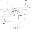
- FIG 9 is an enlarged view of the image reading portion E.
- the first reading portion E1 includes a reading unit 414 of the CIS method, etc., a reading glass 415 which is a transparent member, and an opposing member 425 which opposes the reading glass 415 across a space (gap) through which the document D passes.
- the second reading portion E2 includes a reading unit 416 of the CIS method, etc., a reading glass 417 which is a transparent member, and an opposing member 427 which opposes the reading glass 417 across a space (gap) through which the document D passes.
- the guide member 418 in the embodiment is arranged in an upstream side of the reading glass 417 and in a downstream side of the reading glass 415 with respect to the document conveyance direction D3 at a reading position of the reading unit 416.
- the guide member 418 is configured of the elastic sheet material 418a and is supported by a support member 426.
- the guide member 418 is a folded portion in which a part of an area (a3) of the elastic sheet material 418a is folded so that it overlaps the other part of an area (a2).
- Double sided tape 419 is attached to a surface of one side of the elastic sheet material 418a and the overlapped areas (a2, a3) are adhered to each other via the double sided tape 419. Further, the guide member 418 is adhered to the support member 426 via the double sided tape 419. It is preferable that the double sided tape 419 and the support member 426 are made of conductive material.
- similar materials to those described in the first embodiment may be used.
- the guide member 418 extends from the support member 426 toward a downstream side with respect to the document conveyance direction D3, and toward a direction approaching a sheet passing surface 417a with respect to the vertical direction D4 which is perpendicular to the sheet passing surface 417a of the reading glass 417 (upper side in the figure).
- a leading end portion 418b of the guide member 418 covers an upstream end 417e of the sheet passing surface 417a of the reading glass 417.
- the document D is guided by the guide member 418 and is fed smoothly without getting caught on the edge portion of the upstream end 417e on the sheet passing surface 417a of the reading glass 417, etc.
- the guide member 418 since the guide member 418 is configured of the elastic sheet material 418a, the guide member 418 bends when it is pressed by the document D. Therefore, it is possible to prevent the surface of the document D from rubbing strongly against the leading end portion 418b of the guide member 418.
- the leading end portion 418b of the guide member 418 is configured of the folded portion in which the elastic sheet material 418a is folded back. Therefore, the leading end portion 418b is a more smoothly curved surface than an edge shape of the end surface of the elastic sheet material 418a. Therefore, it is possible to prevent the surface of the document D from rubbing strongly against the leading end portion 418b of the guide member 418, and to suppress generation of paper dust, etc. due to sliding of the leading end portion 418b. Thus, in the embodiment, it is also possible to suppress an appearance of striped noise in the read image which is caused by adhering paper dust, etc. to the sheet passing surface 417a of the reading glass 308.
- the present invention is not limited to those described in the embodiments above, however, the present technology may also be applied to an image reading device which reads image information from a sheet.
- an image reading device which is built into a main assembly of an image forming apparatus (printer) and reads image information on recording material on which an image is formed.
- An image reading apparatus includes a transparent member, a conveyance unit, a reading unit reading an image information through the transparent member from the sheet conveyed by the conveyance unit, and a guide member provided upstream of a reading position where the reading unit reads the image information from the sheet with respect to a sheet conveyance direction.
- the guide member includes a sheet-like sheet member having elasticity. A leading end of a downstream side of the guide member in the sheet conveyance direction is a folded portion formed by folding back the sheet member.
Landscapes
- Engineering & Computer Science (AREA)
- Multimedia (AREA)
- Signal Processing (AREA)
- Physics & Mathematics (AREA)
- General Physics & Mathematics (AREA)
- Health & Medical Sciences (AREA)
- Biomedical Technology (AREA)
- General Health & Medical Sciences (AREA)
- Microelectronics & Electronic Packaging (AREA)
- Facsimile Scanning Arrangements (AREA)
- Feeding Of Articles By Means Other Than Belts Or Rollers (AREA)
- Facsimiles In General (AREA)
Abstract
Description
- This invention relates to an image reading apparatus which reads image information from a sheet and an image forming apparatus which forms an image on the sheet.
- Conventionally, as the image reading apparatus, an apparatus which reads image information from a document or an apparatus which reads image information on a recording material which is formed by the image forming apparatus and feed it back to the image forming apparatus, are known. The image reading apparatus acquires image information by optically scanning the sheet which is fed along a surface of a transparent member such as a reading glass with a reading unit such as a contact image sensor (CIS). In Japanese Laid-Open Patent Application (
JP-A) Hei 11-69043 - However, when a leading end of the guide member which guides the sheet toward a transparent member is a sharp edge, pressure is concentrated on a contact portion between the sheet and the leading end of the guide member. Therefore, foreign matter such as paper dust, toner, etc. may be generated at the leading end of the guide member and adhere to the surface of the transparent member. Adhesion of such foreign matter may cause striped noise to an image data which is scanned by the reading unit.
- A principal object of the present invention is to provide an image reading apparatus which is able to suppress generating paper dust, etc., and an image forming apparatus which is provide with the image reading apparatus.
- According to an aspect of the present invention, there is provide an image reading apparatus comprising: a transparent member, a conveyance unit configured to convey a sheet; a reading unit configured to read an image information through the transparent member from the sheet conveyed by the conveyance unit and; a guide member provided upstream of a reading position where the reading unit reads the image information from the sheet with respect to a sheet conveyance direction and configured to guide the sheet to the reading position, wherein the guide member includes a sheet-like sheet member having elasticity, and wherein a leading end of a downstream side of the guide member with respect to the sheet conveyance direction is a folded portion formed by folding back the sheet member.
- According to another aspect of the present invention, there is provide an image forming apparatus comprising: an image forming unit configured to form an image on a sheet; a transparent member; a conveyance unit configured to convey the sheet on which the image is formed by the image forming unit; a reading unit configured to read an image information through the transparent member from the sheet conveyed by the conveyance unit; and a guide member provided upstream of a reading position where the reading unit reads the image information from the sheet with respect to a sheet conveyance direction and configured to guide the sheet to the reading position, wherein the guide member includes a sheet-like sheet member having elasticity, and wherein a leading end of a downstream side of the guide member with respect to the sheet conveyance direction is a folded portion formed by folding back the sheet member.
- According to further aspect of the present invention, there is provide an image forming apparatus comprising: a transparent member; a conveyance unit configured to convey a sheet; a reading unit configured to read an image information through the transparent member from the sheet conveyed by the conveyance unit; a guide member provided upstream of a reading position where the reading unit reads the image information from the sheet with respect to a sheet conveyance direction and configured to guide the sheet to the reading position; and an image forming unit configured to form an image on a recording material based on the image information read by the reading unit, wherein the guide member includes a sheet-like sheet member having elasticity, and wherein a leading end of a downstream side of the guide member with respect to the sheet conveyance direction is a folded portion formed by folding back the sheet member.
- Further features of the present invention will become apparent from the following description of exemplary embodiments with reference to the attached drawings.
-
-
Figure 1 is a schematic view of the image forming apparatus according to a first embodiment. -
Figure 2 is a schematic view showing an interior of an inspection device according to the first embodiment. -
Figure 3 is a view showing a first reading portion of the inspection device according to the first embodiment. -
Figure 4 is a view showing the first reading portion of the inspection device according to the first embodiment. -
Figure 5 is a view showing a second reading portion of the inspection device according to the first embodiment. -
Figure 6 is a view showing the second reading portion of the inspection device according to the first embodiment. -
Figure 7 is a perspective view of a document reading device according to a second embodiment. -
Figure 8 is a schematic view of the document reading device according to the second embodiment. -
Figure 9 is a view showing the first reading portion and the second reading portion of the document reading device according to the second embodiment. - In the following, embodiments of the present invention will be described with reference to Figures.
-
Figure 1 is a schematic view showing animage forming system 100 as an image forming apparatus according to a first embodiment. Theimage forming system 100 is provided with a configuration in which aninspection device 102 and asorting device 103 are connected in a downstream of aprinter 101 as a main assembly of an image forming apparatus with an image forming function. - The
printer 101 is a full color printer which is provided with animage forming mechanism 10 which forms an image on a recording material P by an electrophotographic process by using four color toners. Theprinter 101 forms an image on the recording material P which is based on image information which is input to a control portion from an external device including information terminal such as a personal computer or an image reader (not shown). It is possible to use a variety of sheets of different sizes and materials, including plain paper and cardboard, plastic film, cloth, surface treated sheet material such as coated paper, and special shape sheet material such as an envelope and an index paper, as a sheet material P. - Further, the
printer 101 is provided with a feeding and conveyingportion 13, a branching and dischargingportion 25, a reversingportion 26, and are-feeding portion 27. Furthermore, theprinter 101 is provided with anoperating portion 21, which is a user interface for theimage forming system 100. The user can input setting information and give an execution instruction to theimage forming apparatus 100 by operating a touch panel, etc. of theoperating portion 21 or an external device which is connected to theimage forming system 100. - The
image forming mechanism 10 includes four image forming units PY, PM, PC and PK (a process unit, an image forming station) which form toner images in yellow, magenta, cyan and black, respectively. Each of the image forming units from PY to PK is provided with aphotosensitive drum 1 as an image bearing member (an electrophotographic photosensitive member), acharging device 2, alaser scanner 3, a developingdevice 4, aprimary transfer roller 6, and adrum cleaner 7. - The four image forming units from PY to PK are arranged along an
intermediary transfer belt 50 as an intermediary transfer member. Theintermediary transfer belt 50 is stretched over adriving roller 51, atension roller 52 and a secondary transferinner roller 53, and is fed and driven in a direction of an arrow R in the figure. Asecondary transfer roller 14 as a transfer member is arranged at a position opposed to the secondary transferinner roller 53 across theintermediary transfer belt 50. Thesecondary transfer portion 15, which is a transfer portion in the embodiment in which an image (a toner image) is transferred to the recording material P, is a nip portion between thesecondary transfer roller 14 and theintermediary transfer belt 50. Further, abelt cleaner 19 is arranged at a position opposed to theintermediary transfer belt 50. - When the
printer 101 receives an instruction to start an image forming operation, thephotosensitive drum 1 of each image forming unit from PY to PK and theintermediary transfer belt 50 are started to drive. Thecharging device 2 uniformly charges a surface of thephotosensitive drum 1. Thelaser scanner 3 emits laser light which is modulated based on an image signal (a video signal) which is generated from image information onto the surface of thephotosensitive drum 1 and writes an electrostatic latent image on the surface of thephotosensitive drum 1. The developingdevice 4 develops the electrostatic latent image by using any of yellow, magenta, cyan or black toner. Thus, a monochromatic toner image is formed on the surface of eachphotosensitive drum 1. - The monochromatic toner image which is borne on four of the
photosensitive drums 1 are primary transferred to theintermediary transfer belt 50 by theprimary transfer roller 6. At this time, when the toner images of each color are transferred multiply so that they are overlapped each other, a full color image is formed on the surface of theintermediary transfer belt 50. While the full color image is borne on theintermediary transfer belt 50, the full color image is fed toward thesecondary transfer portions 15. Incidentally, adhered material such as remaining transfer toner, which is not transferred to theintermediary transfer belt 50 and is remained on the surface of thephotosensitive drum 1, is removed by thedrum cleaner 7. - In parallel with a toner image forming process as described above in the
image forming mechanism 10, the recording material P is supplied one sheet by one sheet from acassette 24 toward thesecondary transfer section 15 by the feeding and conveyingportion 13. Thecassette 24 is an accommodating container in which a number of recording materials P are accommodated. The feeding and conveyingportion 13 includes a feeding unit which feeds the recording material P which is accommodated in thecassette 24 while separating one sheet by one sheet, and a plurality of conveyance units which are arranged along a recording material conveyance passage from thecassette 24 to thesecondary transfer portion 15. The plurality of conveyance units include a registration roller pair which controls a conveying timing of the recording material P to synchronize with the toner image forming process by theimage forming mechanism 10 while correcting for skewness of the recording material P. - When the recording material P reaches the
secondary transfer portion 15, a predetermined voltage is applied to thesecondary transfer roller 14 and the full color image on theintermediary transfer belt 50 is transferred (secondary transfer) to the recording material P. Incidentally, adhered material such as remaining transfer toner, which is not transferred to the recording material P and is remained on the surface of theintermediary transfer belt 50, is removed by thebelt cleaner 19. - The recording material P which has passed through the
secondary transfer portion 15 is introduced into afixing device 16 of a heat fixing method. Thefixing device 16 includes a pair of rotatable members such as a pair of rollers which nip and convey the recording material P, and heating means such as a halogen lamp for heating the image on the recording material P which passes through a nip portion (fixing nip) of the pair of rotatable members. The toner is melted by being heated and pressurized as it passes through the fixing nip, then it is fixed, and a fixed image which is fixed to the recording material P is obtained. - In a case of single-sided printing, the recording material P which has passed through the
fixing device 16 is discharged from theprinter 101 by adischarging roller pair 17 in the branching and dischargingportion 25 and delivered to theinspection device 102. In a case of double-sided printing, the recording material P, which has passed through thefixing device 16 while image is formed on the surface of the recording material P, is fed to the reversingportion 26 through a passage which is branched in the branching and dischargingportion 25. Subsequently, the recording material P is reversed and fed (switched back) in the reversingportion 26 and fed again to theimage forming mechanism 10 through there-feeding portion 27 and the feeding and conveyingportion 13. Then, the recording material P, in which the image is formed on a back side while passing through thesecondary transfer portion 15 and thefixing device 16, is discharged from theprinter 101 by thedischarging roller pair 17 and delivered to theinspection device 102. - The
inspection device 102 is arranged between theprinter 101 which is an upstream device and the downstream device and thesorting device 103 which is a downstream device. When theimage forming apparatus 100 is viewed from a front (a viewpoint inFigure 1 ), theinspection device 102 is arranged between theprinter 101 and thesorting device 103 in a horizontal direction. - The
inspection device 102 includes readingunits printer 101 based on the read image information. For example, the recording material P in which baseline image is recorded is firstly passed through theinspection device 102, and the image information in which thereading units control portion 300. After that, the image information of the recording material P (the recording material P which is an inspection object) which is fed from theprinter 101 is read by the readingunits control portion 300. Thecontrol portion 300 as a determination portion compares the read image information with the registered reference image. In a case that a difference which exceeds an acceptable range (for example, a difference in density, positional shift of a feature point, etc.) is detected, thecontrol portion 300 determines that there is a defect in the image on that recording material P. - The recording material P which is discharged from the
inspection device 102 is delivered to thesorting device 103. Thesorting device 103 switches a discharge destination of the recording material P according to a result of determining whether or not there is a defect in the image by using theinspection device 102. Specifically, a switchingguide 131 switches discharging passages of the recording material P so that the recording material P which is determined that there is no defect is discharged to a lower dischargingtray 132 and the recording material P which is determined that there is a defect discharged to an upper dischargingtray 133. As described above, a series of image forming operations in theimage forming system 100 is completed. - Incidentally, in the embodiment, a configuration which is provided with the
image forming mechanism 10 of the intermediary transfer method as an image forming unit is described, however, an image forming mechanism of a direct transfer method which transfers a toner image directly to a recording material from an image bearing member without an intermediary transfer member may be used. Further, mechanisms other than electrophotographic methods, such as an image forming unit of inkjet method and an offset printing mechanism, may be used as an image forming unit. - Further, a configuration of the
image forming apparatus 100 which is shown inFigure 1 is an example, for example, a sheet processing device (finisher) which performs sheet process such as binding and punching on the material P may be arranged instead of thesorting device 103. Further, theinspection device 102 may be provided with a discharging tray so that theinspection device 102 discharges the recording material P as a deliverable. - Next, an internal configuration of the
inspection device 102 as an image reading device according to the embodiment will be described.Figure 2 is a sectional view showing the internal configuration of theinspection device 102. - As described above, the
inspection device 102 is arranged between theprinter 101 and thesorting device 103 in a horizontal direction (Figure 1 ), and the recording material which is delivered from theprinter 101 is fed toward thesorting device 103. Thus, the recording material conveyance passage of theinspection device 102 extends from an inlet Pi which opens on a side surface of one side of theinspection device 102 in the horizontal direction (right side in the figure), to an outlet Po which opens on a side surface of the other side of the inspection device 102 (left side in the figure). In particular, in the embodiment, a configuration, in which the recording material conveyance passage inside theinspection device 102 extends in a straight line in the substantially horizontal direction when viewed from the front side, is applied. - As shown in
Figure 2 , theinspection device 102 includes a conveyance roller pair 210 (an inlet roller pair), a reading unit 202 (a first reading unit), a reading glass 302 (a first reading glass) and a pressing roller (a platen roller) 203. Further, theinspection device 102 includes a reading unit 204 (a second reading unit), a reading glass 308 (a second reading unit), a pressing roller (a platen roller) 205 and a conveyance roller pair 220 (an outlet roller pair). Furthermore, theinspection device 102 includes a plurality of conveyance guides (221, 222, 224 and 225) which form the recording material conveyance passage, and aninlet sensor 223 and anoutlet sensor 226 as detection units which detect the recording material which is fed through the recording material conveyance passage. - The
reading unit 202, the readingglass 302 and thepressing roller 203 configures a first reading portion R1 which reads image information from a first side of the recording material. Thereading unit 204, the readingglass 308 and thepressing roller 205 configures a second reading portion R2 which reads image information from a second side of the recording material. - In a following description, a recording material conveyance direction D1 refers to a direction of movement of the recording material at a reading position P1 of the
reading unit 202. A vertical direction D2 refers to a direction which is perpendicular to asheet passing surface 302a of the reading glass 302 (a height direction with respect to the reading glass 302). In other words, the vertical direction D2 is a direction which is perpendicular to both the recording material conveyance direction D1 and a sheet width direction at a reading position P1 of thereading unit 202. The vertical direction D2 is also a direction of depth of field of thereading unit 202. The sheet width direction is a direction which is perpendicular to the recording material conveyance direction D1. The sheet width direction is also a direction of a rotational axis of the conveyance roller pairs 210 and 220 and a direction of a main scanning of the readingunits - In the embodiment, a recording material conveyance direction D1', which is a direction of movement of the recording material at a reading position P2 of the
reading unit 204, is substantially same as the recording material conveyance direction D1 which is described above. Further, a vertical direction D2', which is perpendicular to apaper passing surface 308a of thereading glass 308, is substantially same as the vertical direction D2 which is described above. For simplicity, a configuration around thereading unit 204 will be also described below, by using the recording material conveyance direction D1 and the vertical direction D2. However, in such a case that the recording material conveyance passage is bent between the reading positions P1 and P2 of the two readingunits - The
reading unit 202 is a reading unit (a first reading unit) which reads image information through the readingglass 302 as a transparent member (a first transparent member) from a first surface (a surface of lower side in the figure) of the recording material which is fed along the recording material conveyance passage. Thereading unit 204 is a reading unit (a second reading unit) which reads image information through the readingglass 308 as a transparent member (a second transparent member) from a second surface (a surface of upper side in the figure) which is an opposite side of the first surface of the recording material which is fed along the recording material conveyance passage. - Contact image sensors (CIS) are used for the reading
units units reading unit 202 is opposed to a back of thereading glass 302 in the vertical direction D2 at the reading position P1, and the sensor board of thereading unit 204 is opposed to a back of thereading glass 308 in the vertical direction D2 at the reading position P2. The readingunits glasses - Incidentally, as the reading
units units - The reading
glass 302 is arranged at the reading position P1, and is opposed to thepressing roller 203 which is an opposing member in the vertical direction D2 across a space (a gap) through which the recording material passes. The readingglass 302 includes thesheet passing surface 302a which extends in the recording material conveyance direction D1 and the sheet width direction on a surface of thepressing roller 203 side (a side of space through which the recording material passes) in the vertical direction D2. A position of thesheet passing surface 302a of thereading glass 302 in the vertical direction D2, is set to match a focal point of thereading unit 202. - The reading
glass 308 is arranged at the reading position P2, and is opposed to thepressing roller 205 which is an opposing member in the vertical direction D2 across a space (a gap) through which the recording material passes. The readingglass 308 includes thesheet passing surface 308a which extends in the recording material conveyance direction D2 and the sheet width direction on a surface of thepressing roller 205 side (a side of space through which the recording material passes) in the vertical direction D2. A position of thesheet passing surface 308a of thereading glass 302 in the vertical direction D2, is set to match a focal point of thereading unit 204. - The
conveyance roller pair 210 in an upstream side is arranged upstream of the reading position P1 of thereading unit 202 with respect to the recording material conveyance direction D1, and conveys the recording material which is fed into the recording material conveyance passage through the inlet Pi toward the reading position P1. Theconveyance roller pair 220 in a downstream side is arranged downstream of the reading position P2 of thereading unit 204 with respect to the recording material conveyance direction D1, and conveys the recording material which is fed into the recording material conveyance passage through the outlet Po toward the reading position P2. - The conveyance roller pairs 210 and 220 are examples of the conveyance units which convey the sheet which is read through the reading position P1 of the
reading unit 202. Theconveyance roller pair 210 is an example of a first roller pair which is arranged upstream of the reading position P1 with respect to the sheet conveyance direction, and theconveyance roller pair 220 is an example of a second roller pair which is arranged downstream of the reading position P1 with respect to the sheet conveyance direction. Incidentally, two of the readingunits units conveyance roller pair 210 and the intermediary roller pair and a nip line for the second reading portion R2 is a straight line which passes through a nip portion between the intermediary roller pair and theconveyance roller pair 220. - The
conveyance roller pair 210 in the upstream side is configured of a drivingroller 211 and aroller 212 which is a driven roller which rotates in accordance with the drivingroller 211. The drivingroller 211 configures of asteel shaft 211a, which extends in the sheet width direction, to which two of silicon rubber outerperipheral portions 211b (a recording material contact portion, a roller main body) whose outer diameters are 20mm are attached. Theroller 212 is provided at a position corresponding to the outerperipheral portion 211b of the drivingroller 211 with respect to the sheet width direction and is made of POM (polyacetal resin). A shaft portion of theroller 212 is rotationally supported by a frame of theinspection device 102, and theroller 212 is urged against the drivingroller 211 by an unshown spring member with an urging force of 10N in total. When the drivingroller 211 is rotationally driven by power of an unshown motor, theconveyance roller pair 210 nips and conveys the recording material to the nip portion N1 between the drivingroller 211 and theroller 212. - A configuration of the
conveyance roller pair 220 in the downstream side is substantially same as a configuration of theconveyance roller pair 210 in the upstream side. That is, theconveyance roller pair 220 includes the driving roller and the roller which is a driven roller which rotates in accordance with the driving roller, and nips and conveys the recording material at the nip portion N2 between the driving roller and the roller. - Hereafter, when viewed in the sheet width direction, a virtual strait line which passes through the nip portions N1 and N2 of the conveyance roller pairs 210 and 220 in the upstream side and the downstream side is a nip line Ln. In the embodiment, a direction of the nip line Ln is substantially parallel to the recording material conveyance direction D1.
- Of a plurality of conveyance guides which are provided with the
inspection device 102, an inlet guide lower 221 and an inlet guide upper 222 extend from a downstream side of the nip portion N1 of theconveyance roller pair 210 to an upstream side of the nip portion N1 with respect to the recording material conveyance direction D1 and form an inlet Pi of the recording material conveyance passage. In the upstream side of the nip portion N1, the inlet guide lower 221 and the inlet guide upper 222 are inclined with respect to the recording material conveyance direction D1 so that the inlet guide lower 221 and the inlet guide upper 222 are away each other with respect to the vertical direction D2 toward the upstream of the recording material conveyance direction D1 (that is, so that a width of the inlet Pi is widened). - Further, of a plurality of conveyance guides which are provided with the
inspection device 102, an outlet guide lower 224 and an outlet guide upper 225 extend from an upstream side of the nip portion N2 of theconveyance roller pair 220 to a downstream side of the nip portion N2 with respect to the recording material conveyance direction D1 and form an outlet Po of the recording material conveyance passage. In the upstream side of the nip portion N2, the outlet guide lower 224 and the outlet guide upper 225 are inclined with respect to the recording material conveyance direction D1 so that the outlet guide lower 224 and the outlet guide upper 225 are away each other with respect to the vertical direction D2 toward the upstream of the recording material conveyance direction D1. - Between the inlet guide lower 221 and the inlet guide upper 222 and between the outlet guide lower 224 and the outlet guide upper 225 with respect to the vertical direction D2, the recording material conveyance passage is formed as a space through which the recording material passes. Further, the recording material conveyance passage is formed between the reading
glass 302 and thepressing roller 203 and between the readingglass 308 and thepressing roller 205 with respect to the vertical direction D2. - It is possible to use SUS420CP (martensitic stainless steel) as a material for the inlet guide lower 221, the inlet guide upper 222, the outlet guide lower 224 and the outlet guide upper 225. Further, it is preferable that a contact surface with the recording material is polished, the surface smoothness is increased and the recording material is prevented to be scratched.
- In the embodiment, at least the recording material conveyance passage from the
conveyance roller pair 210 which is arranged in an upstream side to theconveyance roller pair 220 with respect to the reading positions P1 and P2 is a straight passage which extends in a straight line when viewed in the sheet width direction. In other words, the conveyance guides (221, 222, 224 and 225) which form the recording material conveyance passage, the readingglasses pressing rollers - Incidentally, it is possible to arrange so that one of the conveyance guides, the reading
glasses rollers sheet passing surfaces glasses sheet passing surfaces - The
inlet sensor 223 is arranged upstream of theconveyance roller pair 210 with respect to the recording material conveyance direction D1. Theoutlet sensor 226 is arranged downstream of theconveyance roller pair 220 with respect to the recording material conveyance direction D1. As for theinlet sensor 223 and theoutlet sensor 226, it is possible to use a known sensor configuration which is capable of detecting a sheet-like recording material. For example, it is possible to use a photoelectric sensor (a photo reflector) which emits light toward the recording material conveyance passage and detects the reflected light from the recording material. Further, it may be a configuration that a photoelectric sensor (a photo interrupter) in which light is shielded by a flag member detects that the flag member which is protruding into the recording material conveyance passage is pressed and oscillated by the recording material. - A series of operations in which the
inspection device 102 reads image information while conveying the recording material will be described. The recording material P which enters into the recording material conveyance passage through the inlet Pi is guided to the nip portion N1 of theconveyance roller pair 210 by the inlet guide lower 221 and the inlet guide upper 222 which are tapered, while suppressing flapping (positional deviation) in the vertical direction D2. In the process, thecontrol unit 300 of theinspection device 102 recognizes that the recording material is fed from theprinter 101 when a leading end of the recording material is detected by theinlet sensor 223. - The
control portion 300 of theinspection portion 102 determines a timing when the readingunits inlet sensor 223. Further, a conveyance defect (jam) of the recording material is detected based on a detection result of theinlet sensor 223, such as a case that theinlet sensor 223 does not detect the recording material before a predetermined time based on a conveyance information of the recording material which is notified by theprinter 101 is elapsed. - The recording material which arrives at the
conveyance roller pair 210 is fed along thesheet passing surfaces glasses reading unit 202 when the recording material passes through the reading position P1, and image information on the second side of the recording material is read by thereading unit 204 when the recording material passes through the reading position P2. That is, theinspection device 102 is capable of reading image information from both sides of the recording material while the recording material passes through the recording material conveyance passage only once without a reverse conveyance of the recording material, etc. Here, a conveyance speed of the recording material P which is discharged from theprinter 101 is substantially same as a conveyance speed of the recording material P in theinspection device 102. - The recording material which has passed through the reading position P2 of the
reading unit 204 in the downstream side is guided to the nip portion N2 of the conveyance roller pair by the outlet guide lower 224 and the outlet guide upper 225. And by means of theconveyance roller pair 220, the recording material is discharged through the outlet Po to an outside of theinspection device 102 and delivered to thesorting device 103. In the process, thecontrol portion 300 of theinspection device 102 recognizes that discharge of the recording material is completed when a trailing end of the recording material is detected by theoutlet sensor 226. Further, thecontrol portion 300 of theinspection device 102 detects of a conveyance defect (jam) of the recording material based on a detection result of theoutlet sensor 226. - By the way, the
inspection device 102 is a device which reads image information from a variety of recording materials of different materials, including thin paper with low stiffness and thick paper with high stiffness. In the embodiment, the image information is read, while the recording material is fed in a straight passage which extends in a straight line from theconveyance roller pair 210 in the upstream side of the reading position P1 and P2 to theconveyance roller pair 220 in the downstream side of the reading position P1 and P2. Therefore, it is possible to suppress deviation (flapping) from an ideal position of the recording material with respect to the recording material conveyance direction D1 or the vertical direction D2 by action of unnecessary external force on the recording material while the recording material is fed through the reading positions P1 and P2. - When a conveyance speed of the recording material fluctuates, it leads to magnification fluctuation or geometric fluctuation of a read image, and when a position of the recording material in the vertical direction D2 deviates, accuracy of the read image is decreased (blurred). On the other hand, in the embodiment, a straight passage configuration is applied, and the reading
glasses units - In the embodiment, in order to further improve accuracy of reading, the
sheet passing surfaces glasses sheet passing surfaces glasses - Incidentally, around and in the downstream side of the nip portion N1 of the
conveyance roller pair 210, it is preferable that the inlet guide lower 221 and the inlet guide upper 222 extend in the recording material conveyance direction D1 in substantially parallel with each other. At the reading positions P1 and P2, it is preferable that thesheet passing surfaces glasses conveyance roller pair 220, it is preferable that the outlet guide lower 224 and the outlet guide upper 225 extend in the recording material conveyance direction D1 in substantially parallel with each other. - Next, details of the first reading portion R1 and a
guide member 305 which is provided with the first reading portion R1 will be described by usingFigure 3 andFigure 4 .Figure 3 is a view showing the first reading portion R1 when viewed in the sheet width direction, andFigure 4 is a view showing the first reading portion R1 while the recording material P passes through the first reading portion R1. - As shown in
Figure 3 , the first reading portion R1 is provided with theguide member 305 which is configured of anelastic sheet material 305a (a sheet member, film material, and first sheet material). Theguide member 305 is attached to doublesided tape 304 on one side of theelastic sheet material 305a, and is adhered to asheet metal 306 as a support member via a doublesided tape 304. - Here, a
leading end portion 303 in a downstream side of theguide member 305, is a folded portion in which a part of an area (a3) of theelastic sheet material 305a is folded so that it overlaps the other part of an area (a2). Specifically, theelastic sheet material 305a includes a first area a1 as a supported portion (a base portion) which is supported (fixed) to thesheet metal 306, a second area a2 which extends downstream from the first area a1 with respect to the recording material conveyance direction D1, and a third area a3 which is folded back from the second region a2. The third area a3 extends from a downstream end of the second area a2 with respect to the recording material conveyance direction D1 to an upstream side with respect to the recording material conveyance direction D1, and overlaps the second area a2. Thus, theleading end portion 303 of theguide member 305 in the embodiment is the folded portion in which the third area a3 of theelastic sheet material 305a is folded back so that it overlaps the second area a2. - The third area a3 of the
elastic sheet material 305a is adhered to the second area a2 by the doublesided tape 304. Therefore, theguide member 305 maintains the shape of theelastic sheet material 305a which is folded back. That is, an end surface a4 of theelastic sheet material 305a is not exposed to theleading end portion 303 of theguide member 305. Therefore, it is possible to suppress generating paper dust as will be described below. Further, the doublesided tape 304 has a role to adhere theguide member 305 to thesheet metal 306 and a role to attach the second area a2 of theguide member 305 to the third area a3, so it is possible to reduce costs. Incidentally, the end surface a4 is, for example, a cut surface when theelastic sheet material 311a is cut from an original sheet. - Incidentally, in the
elastic sheet material 305a, an area which includes the end surface a4 (the third area a3) is folded back so that it is positioned at a back side of an area which does not include the end surface a4 (the second area a2) when viewed from a side of space through which the recording material passes (upper side in the figure) with respect to the vertical direction D2. That is, the end surface a4 of theelastic sheet material 305a is positioned on an opposite side of space through which the recording material passes across the second area a2 of theelastic sheet material 305a. Thus, it is possible to prevent the recording material from getting caught on the end surface a4 of theelastic sheet material 305a which is fed through the space described above. - Incidentally, the "folded portion" refers to a shape of the
leading end portion 303 in a case that the end surface a4 of theelastic sheet material 305a is positioned in upstream side of a downstream end (the leading end portion 303) of theguide member 305 with respect to the recording material conveyance direction D1. That is, in theleading end portion 303 of theguide member 305, at least, the end surface a4 may only be positioned in the upstream side of the downstream end of theguide portion 305 with respect to the recording material conveyance direction D1, and the second area a2 and the third area a3 may not be adhered to each other. - A material of the
elastic sheet material 305a is elastic enough to flex when it is pressed by a general recording material. Thus, rigidity of theelastic sheet material 305a is lower than the conveyance guides (221, 222, 224 and 225) which is described above and whose rigidity is high enough that deflection is negligible even when it is pressed by the recording material and an opposingguide 307 which will be described below. As an example, ultrahigh molecular polyethylene film is used for theelastic sheet material 305a. - Incidentally, as the
elastic sheet material 305a, it is preferable to use a material whose modulus of elasticity (Young's modulus) is from 0.8GPa to 1.2GPa. When its Young's modulus is too low, theguide member 305 may be deformed even by very weak force and may not provide proper guiding action, and when its Young's modulus is too high, contact pressure between theleading end portion 303 of theguide member 305 and the recording material is large and paper dust, etc. is likely to be generated. Further, as theelastic sheet material 305a, it is preferable to use a material whose volume resistivity is 10^3Ω-cm to 10^5Ω-cm. By setting the volume resistivity in the range as described above, it is easier to perform a function of adsorbing paper dust, etc. on the surface of theguide member 305 since the conductive doublesided tape 304 is provided inside the foldedelastic sheet material 305a. In the example using the ultrahigh molecular polyethylene film which is described above, the film thickness is 0.1mm, Young's modulus is 1.0GPa, and the volume resistivity is 10^4Ω-cm. - It is preferable that a material of the double
sided tape 304 is conductive, such as aluminum foil tape. Further, the thickness is 0.1mm, for example. The doublesided tape 304 is an example of an adhesive layer which is provided on a surface of an inner side at the folded portion of theelastic sheet material 305a, and for example, an adhesive may be applied to one side of theelastic sheet material 305a. Further, for example, an overlapping portion each other while theelastic sheet material 305a is folded may be adhered (fixed) by a method of heat welding, single sided tape, a staple, etc. - The
guide member 305 is arranged upstream of the reading position P1 with respect to the recording material conveyance direction D1 and on a same side as the readingglass 302 of space through which the recording material passes with respect to the vertical direction D2. Theguide member 305 extends downstream of the first area a1 which is supported by thesheet metal 306 with respect to the recording material conveyance direction D1 and in a side of space through which the recording material passes (upper side in the figure) with respect to the vertical direction D2. - A length of the
guide member 305 with respect to the sheet width direction is set equal to or greater than a width of thesheet passing surface 302a of thereading glass 302 with respect to the sheet width direction. While the recording material is not being fed, theguide member 305 is contactlessly arranged by being spaced apart from the readingglass 302 with a predetermined gap (for example, approximately 1mm). When viewed from an upstream side toward a downstream side with respect to the recording material conveyance direction D1, theguide member 305 covers at least a part (preferably all) of thesheet passing surface 302a of thereading glass 302. - The
leading end portion 303 of theguide member 305 protrudes from thesheet passing surface 302a of thereading glass 302 to the side of the space (the upper side in the figure) through which the recording material passes with respect to the vertical direction D2. In particular, theleading end portion 303 of theguide member 305 protrudes to the side of the space through which the recording material passes with respect to the vertical direction D2, at least, from anupstream end 302e of thesheet passing surface 302a which extends in the recording material conveyance direction D1. Incidentally, a tapered shape is provided on thesheet passing surface 302a in an example of a configuration which is shown in the figure, and theupstream end 302e of thesheet passing surface 302a is positioned downstream from aside surface 302b of an upstream side of thereading glass 302 with respect to the recording material conveyance direction D1. - Further, the leading end of the
guide member 305 intrudes into the nip line Ln which is described above with respect to the vertical direction D2. That is, theguide member 305 intersects the nip line Ln. - The opposing
guide 307 is arranged in a position to which, at least, a part of theguide member 305 is opposed with respect to the vertical direction D2. The opposingguide 307 opposes a surface of an opposite side of a surface with which theguide member 305 of the recording material is contacted, and is a conveyance guide to guide the recording material to a gap between the readingglass 302 and thepressing roller 203. The opposingguide 307 extends downstream of the recording material conveyance direction D1 and so as to approach the nip line Ln with respect to vertical direction D2. Theleading end 307a of the opposingguide 307 opposes thesheet passing surface 302a of thereading glass 302 in the vertical direction D2 on the upstream side of the reading position P1 with respect to the recording material conveyance direction D1. Unlike theguide member 305, the opposingguide 307 is rigid enough to ignore deflection even when it is pressed by the recording material, and theleading end 307a of the opposingguide 307 is arranged so that it does not intrude into the nip line Ln. The opposingguide 307 is, for example, made of same stainless steel as the conveyance guides (221, 222, 224 and 225) which are described above. - In a case that the recording material P is fed to the first reading portion R1 as shown in
Figure 4 , the recording material P is fed while it contacts with theguide member 305. Here, while the recording material P is not being fed, theleading end portion 303 of theguide member 305 protrudes from thesheet passing surface 302a of thereading glass 302 in the vertical direction D2. Therefore, the recording material P is fed smoothly without getting caught on the edge portion of theupstream end 302e on thesheet passing surface 302a of thereading glass 302 and theside surface 302b on the upstream side of thereading glass 302. - Further, since the
guide member 305 is configured of theelastic sheet material 305a, theguide member 305 bends and theleading end portion 303 is retracted to the nip line Ln, when it is pressed by the recording material P. Therefore, it is possible to prevent the surface of the recording material P from rubbing strongly against theleading end portion 303 of theguide member 305. - Furthermore, in the embodiment, the
leading end portion 303 of theguide member 305 is configured of the folded portion in which theelastic sheet material 305a is folded back. Therefore, theleading end portion 303 is a more smoothly curved surface than an edge shape of the end surface a4 of theelastic sheet material 305a. Therefore, it is possible to prevent the surface of the recording material P from rubbing strongly against theleading end portion 303 of theguide member 305, and to suppress generation of foreign matters such as paper dust and toner dust (collectively referred to as paper dust, etc.) due to sliding of theleading end portion 303. Thus, in the embodiment, it is possible to suppress an appearance of striped noise in the read image which is caused by adhering paper dust, etc. to thesheet passing surface 302a of thereading glass 302, and to suppress an occurrence of a reading error, for example, by theinspection device 102. - In particular, in the embodiment, the
leading end portion 303 of theguide member 305 intrudes into the nip line Ln, and is arranged so that the recording material, which is fed along the nip line Ln, easily slides with theleading end portion 303 of theguide member 305. In such a configuration, it is possible to maintain a guiding function of theguide member 305 and to suppress generation of paper dust, etc. by sliding with theleading end portion 303. Further, even in a case that thesheet passing surface 302a of thereading glass 302 is positioned at a position which is substantially same as the nip line Ln in order to improve reading accuracy, it is possible to suppress generation of paper dust, etc. by sliding with theleading end portion 303 of theguide member 305 which protrudes to the sheet passing surfaced 302a. - Further, in the embodiment, the
guide member 305 is formed by adhering with the conductive double sided 304 while theelastic sheet material 305a is folded back. Since theguide member 305 includes a conductive adhesive layer such as conductive double sided tape, when charged particles such as paper dust are attached to theguide member 305, charges move inside the adhesive layer due to electrostatic induction, and charges which negate charges of the particles move to a position which is opposed to the particles. Thus, it is possible to electrostatically adsorb charged particles such as paper dust to theguide member 305 and to suppress accumulating the particles on thesheet passing surface 302a of thereading glass 302. - Further, in the embodiment, a support member which supports the
guide member 305 is configured of theconductive sheet metal 306, and theelastic sheet material 305a is adhered to thesheet metal 306 by the conductive doublesided tape 304. That is, in the embodiment, at least, a part of theguide member 305 is electrically conductive and is a configuration which is electrically connected to the conductive support member. Due to such a configuration, it is possible to electrostatically adsorb charged particles such as paper dust to theguide member 305, and to suppress accumulating the particles on thesheet passing surface 302a of thereading glass 302. Incidentally, instead of the conductive doublesided tape 304, it is also possible to use theelastic sheet material 305a itself as a conductive material. Further, thesheet metal 306 is possible to connect to ground potential through a frame (a metal frame) of theinspection device 102. - Incidentally, in the embodiment, the
guide member 305, which is arranged on a same side as the readingglass 302 with respect to the recording material conveyance passage (the space through which the sheet passes) in the vertical direction D2, is formed of theelastic sheet material 305a. Aguide member 305 is not limited to this, however, a guide member (for example, the opposing guide 307) on an opposite side of thereading glass 302 with respect to the recording material conveyance passage (the space through which the sheet passes) may be formed of an elastic sheet material, and a leading end portion may be a folded portion of the elastic sheet material. Thus, it is possible to suppress generation of paper dust, etc. at the leading end portion of the guide member. Incidentally, since paper dust, etc. which is generated on a same side as the readingglass 302 more easily adheres to thereading glass 302, it is possible to suppress more effectively adhering paper dust to thereading glass 302 due to a configuration in the embodiment that theguide member 305 is formed of theelastic sheet material 305a. - Next, details of the second reading portion R2 and a
guide member 311 which is provided with the second reading portion R2 will be described by usingFigure 5 andFigure 6 .Figure 5 is a view of the second reading portion R2 when viewed in the sheet width direction, andFigure 6 is a view showing a state that the recording material P passes through the second reading portion R2. Except that a positional relationship is reversed with respect to the vertical direction, a configuration of the second reading portion R2 is substantially same as that of the first reading portion R1. - As shown in
Figure 6 , the second reading portion R2 is provided with theguide member 311 which is configured of anelastic sheet material 311a (a sheet member, film material, and first sheet material). Theguide member 311 is attached to doublesided tape 310 on one side of theelastic sheet material 311a, and is adhered to asheet metal 312 as a support member via a doublesided tape 310. - Here, a
leading end portion 309 of theguide member 311, is a folded portion in which a part of an area (a3) of theelastic sheet material 311a is folded so that it overlaps the other part of an area (a2). Specifically, theelastic sheet material 311a includes a first area a1 as a supported portion (a base portion) which is supported (fixed) to thesheet metal 312, a second area a2 which extends downstream from the first area a1 with respect to the recording material conveyance direction D1, and a third area a3 which is folded back from the second region a2. The third area a3 extends from a downstream end of the second area a2 with respect to the recording material conveyance direction D1 to an upstream side with respect to the recording material conveyance direction D1, and overlaps the second area a2. Thus, theleading end portion 309 of theguide member 311 in the embodiment is the folded portion in which the third area a3 of theelastic sheet material 311a is folded back so that it overlaps the second area a2. - The third area a3 of the
elastic sheet material 311a is adhered to the second area a2 by the doublesided tape 310. Therefore, theguide member 311 maintains the shape of theelastic sheet material 311a which is folded back. That is, an end surface a4 of theelastic sheet material 311a is not exposed to theleading end portion 309 of theguide member 311. Therefore, it is possible to suppress generating paper dust as will be described below. Further, the doublesided tape 310 has a role to adhere theguide member 311 to thesheet metal 312 and a role to attach the second area a2 of theguide member 311 to the third area a3, so it is possible to reduce costs. Incidentally, the end surface a4 is normally a cut surface when theelastic sheet material 311a is cut from an original sheet. - Incidentally, in the
elastic sheet material 311a, an area which includes the end surface a4 (the third area a3) is folded back so that it is positioned at a back side of an area which does not include the end surface a4 (the second area a2) when viewed from a side of space through which the recording material passes (lower side in the figure) with respect to the vertical direction D2. That is, the end surface a4 of theelastic sheet material 311a is positioned on an opposite side of space through which the recording material passes across the second area a2 of theelastic sheet material 311a. Thus, it is possible to prevent the recording material from getting caught on the end surface a4 of theelastic sheet material 311a which is fed through the space described above. - The
elastic sheet material 311a and the doublesided tape 310 are possible to use same materials as theelastic sheet material 305a and the doublesided tape 304 of the first reading portion R1, however, different materials may be used. As an example, ultrahigh molecular polyethylene film of thickness 0.1mm, Young's modulus 1.0GPa and volume resistivity of 10^4Ω-cm is used for theelastic sheet material 311a. Further, for example, a 0.1mm thick tape which is made of conductive aluminum foil is used for the doublesided tape 310. - The
guide member 311 is arranged upstream of the reading position P2 with respect to the recording material conveyance direction D1 and on a same side as the readingglass 308 of space through which the recording material passes with respect to the vertical direction D2. Theguide member 311 extends downstream of the first area a1 which is supported by thesheet metal 312 with respect to the recording material conveyance direction D1 and in a side of space through which the recording material passes (upper side in the figure) with respect to the vertical direction D2. - A length of the
guide member 311 with respect to the sheet width direction is set equal to or greater than a width of thesheet passing surface 308a of thereading glass 308 with respect to the sheet width direction. While the recording material is not being fed, theguide member 311 is contactlessly arranged by being spaced apart from the readingglass 308 with a predetermined gap (for example, approximately 1mm). When viewed from an upstream side toward a downstream side with respect to the recording material conveyance direction D1, theguide member 311 covers at least a part (preferably all) of thesheet passing surface 308a of thereading glass 308. - The
leading end portion 309 of theguide member 311 protrudes from thesheet passing surface 308a of the readingportion 308 to the side of the space (the lower side in the figure) through which the recording material passes with respect to the vertical direction D2. In particular, theleading end portion 309 of theguide member 311 protrudes to the side of the space through which the recording material passes with respect to the vertical direction D2, at least, from anupstream end 308e of thesheet passing surface 308a which extends in the recording material conveyance direction D1. - Further, the leading end of the
guide member 311 intrudes into the nip line Ln which is described above with respect to the vertical direction D2. That is, theguide member 311 intersects the nip line Ln. - The opposing
guide 313 is arranged in a position to which, at least, a part of theguide member 311 is opposed with respect to the vertical direction D2. The opposingguide 313 opposes a surface of an opposite side of a surface with which theguide member 311 of the recording material is contacted, and is a conveyance guide to guide the recording material to a gap between the readingglass 308 and thepressing roller 203. The opposingguide 313 extends downstream of the recording material conveyance direction D1 and so as to approach the nip line Ln with respect to vertical direction D2. Theleading end 313a of the opposingguide 313 opposes thesheet passing surface 308a of thereading glass 308 in the vertical direction D2 on the upstream side of the reading position P1 with respect to the recording material conveyance direction D1. Unlike theguide member 311, the opposingguide 313 is rigid enough to ignore deflection even when it is pressed by the recording material, and theleading end 313a of the opposingguide 313 is arranged so that it does not intrude into the nip line Ln. The opposingguide 313 is, for example, made of same stainless steel as the conveyance guides (221, 222, 224 and 225) which are described above. - In a case that the recording material P is fed to the second reading portion R2 as shown in
Figure 6 , the recording material P is fed while it contacts with theguide member 311. Here, while the recording material P is not being fed, theleading end portion 309 of theguide member 311 protrudes from thesheet passing surface 308a of thereading glass 308 in the vertical direction D2. Therefore, the recording material P is fed smoothly without getting caught on the edge portion of theupstream end 308e on thesheet passing surface 308a of thereading glass 308 and theside surface 308b on the upstream side of thereading glass 308. - Further, since the
guide member 311 is configured of theelastic sheet material 311a, theguide member 311 bends and theleading end portion 309 is retracted to the nip line Ln, when it is pressed by the recording material P. Therefore, it is possible to prevent the surface of the recording material P from rubbing strongly against theleading end portion 309 of theguide member 311. - Furthermore, in the embodiment, the
leading end portion 309 of theguide member 311 is configured of the folded portion in which theelastic sheet material 311a is folded back. Therefore, theleading end portion 309 is a more smoothly curved surface than an edge shape of the end surface a4 of theelastic sheet material 311a. Therefore, it is possible to prevent the surface of the recording material P from rubbing strongly against theleading end portion 309 of theguide member 311, and to suppress generation of paper dust, etc. due to sliding of theleading end portion 309. Thus, in the embodiment, it is possible to suppress an appearance of striped noise in the read image which is caused by adhering paper dust, etc. to thesheet passing surface 308a of thereading glass 308, and to suppress an occurrence of a reading error, for example, by theinspection device 102. - In particular, in the embodiment, the
leading end portion 309 of theguide member 311 intrudes into the nip line Ln, and is arranged so that the recording material, which is fed along the nip line Ln, easily slides with theleading end portion 309 of theguide member 311. In such a configuration, it is possible to maintain a guiding function of theguide member 311 and to suppress generation of paper dust, etc. by sliding with theleading end portion 309. Further, even in a case that thesheet passing surface 308a of thereading glass 308 is positioned at a position which is substantially same as the nip line Ln in order to improve reading accuracy, it is possible to suppress generation of paper dust, etc. by sliding with theleading end portion 309 of theguide member 311 which protrudes to the sheet passing surfaced 308a. - Further, in the embodiment, the
guide member 311 is formed by adhering with the conductive double sided 310 while theelastic sheet material 311a is folded back. Since theguide member 311 includes a conductive adhesive layer such as conductive double sided tape, when charged particles such as paper dust are attached to theguide member 311, charges move inside the adhesive layer due to electrostatic induction, and charges which negate charges of the particles move to a position which is opposed to the particles. Thus, it is possible to electrostatically adsorb charged particles such as paper dust to theguide member 311 and to suppress accumulating the particles on thesheet passing surface 308a of thereading glass 308. - Further, in the embodiment, a support member which supports the
guide member 311 is configured of theconductive sheet metal 312, and theelastic sheet material 311a is adhered to thesheet metal 312 by the conductive doublesided tape 310. That is, in the embodiment, at least, a part of theguide member 311 is electrically conductive and is a configuration which is electrically connected to the conductive support member. Due to such a configuration, it is possible to electrostatically adsorb charged particles such as paper dust to theguide member 311, and to suppress accumulating the particles on thesheet passing surface 308a of thereading glass 308. Incidentally, instead of the conductive doublesided tape 310, it is also possible to use theelastic sheet material 311a itself as a conductive material. Further, thesheet metal 312 is possible to connect to ground potential through a frame (a metal frame) of theinspection device 102. - In the embodiment described above, the
elastic sheet materials sheet metals guide members elastic sheet materials entire guide members elastic sheet materials elastic sheet materials sheet metal leading end portion guide members - Further, based on image information which is read by the
inspection device 102 after test image is formed by theprinter 101, conditions for executing an image forming operation at theprinter 101 may be adjusted (for example, correction of image magnification, position correction, color correction, etc.). That is, the image reading device in the embodiment may be an adjustment unit for automatically adjusting the execution conditions of the image forming operation in theimage forming system 100. - The
inspection device 102, which is an example of an image reading device, is described in the first embodiment, however, the present technology can be applied to an image reading device other than inspection devices. As a second embodiment, an example of a configuration in which the present technology is applied to a document reading device which is another example of an image reading device will be described. -
Figure 7 is a perspective view of adocument reading device 400 according to the embodiment.Figure 8 is a schematic view showing a sectional configuration of thedocument reading device 400. Thedocument reading device 400 is provided with areader 420 and anADF 401, and reads image information by optically scanning a document D. "ADF" stands for an Automatic Document Feeder. The document D is a sheet which is paper such as printing paper and an envelope, plastic film such as a sheet for overhead projectors, cloth, etc. - As shown in
Figure 7 andFigure 8 , thedocument reading device 400 is provided with an image reading portion E which includes a first reading portion E1 which reads image information from a first surface of the document D, and a second reading portion E2 which reads image information from a second surface of the documentD. An ADF 401 is provided with adocument tray 402, a dischargingtray 403, a feedingroller 404, aconveyance roller 405, a separatingroller 406, a conveyance roller pairs 408 and 409, a dischargingroller pair 410, aninner structure portion 413, and an opening/closing cover 411. The feedingroller 404, theconveyance roller 405, the conveyance roller pairs 407, 408, and 409, and the dischargingroller pair 410 function as a conveyance unit which conveys a sheet. TheADF 401 is provided in an openable with respect to a top surface of thereader 420. Further, the opening/closing cover 411 is provided in an openable with respect to theinner structure portion 413, and it is possible to open up a document conveyance passage inside theADF 401. - A flow of a document reading operation which includes conveyance of feeding, reading, and discharging of the document D will be described by using
Figure 8 . The document D which is set in thedocument tray 402 by a user is fed to theconveyance roller 405 by a rotation of the feedingroller 404 which is a feeding unit. The document D is fed one by one in a separating nip between theconveyance roller 405 and the separatingroller 406 which is pressed against theconveyance roller 405 by an urging force of a spring member, etc. The document D which has passed through the separating nip is fed to the image reading portion E by the conveyance roller pairs 407 and 408. - And, while the document D passes through the reading positions of the first reading portion E1 and the second reading portion E2, the first reading portion E1 and the second reading portion E2 read image information from both sides of the document. The document which has passed through the reading positions is delivered to the discharging
roller pair 410 via theconveyance roller pair 409, and is discharged to the dischargingtray 403 by the dischargingroller pair 410. -
Figure 9 is an enlarged view of the image reading portion E. The first reading portion E1 includes areading unit 414 of the CIS method, etc., areading glass 415 which is a transparent member, and an opposingmember 425 which opposes the readingglass 415 across a space (gap) through which the document D passes. The second reading portion E2 includes areading unit 416 of the CIS method, etc., areading glass 417 which is a transparent member, and an opposingmember 427 which opposes the readingglass 417 across a space (gap) through which the document D passes. - The
guide member 418 in the embodiment is arranged in an upstream side of thereading glass 417 and in a downstream side of thereading glass 415 with respect to the document conveyance direction D3 at a reading position of thereading unit 416. Theguide member 418 is configured of theelastic sheet material 418a and is supported by asupport member 426. - The
guide member 418 is a folded portion in which a part of an area (a3) of theelastic sheet material 418a is folded so that it overlaps the other part of an area (a2). Doublesided tape 419 is attached to a surface of one side of theelastic sheet material 418a and the overlapped areas (a2, a3) are adhered to each other via the doublesided tape 419. Further, theguide member 418 is adhered to thesupport member 426 via the doublesided tape 419. It is preferable that the doublesided tape 419 and thesupport member 426 are made of conductive material. For other details of theelastic sheet material 418a and the doublesided tape 419, similar materials to those described in the first embodiment may be used. - The
guide member 418 extends from thesupport member 426 toward a downstream side with respect to the document conveyance direction D3, and toward a direction approaching asheet passing surface 417a with respect to the vertical direction D4 which is perpendicular to thesheet passing surface 417a of the reading glass 417 (upper side in the figure). Aleading end portion 418b of theguide member 418 covers anupstream end 417e of thesheet passing surface 417a of thereading glass 417. - Therefore, in a case that the document D is fed from the first reading portion E1 to the second reading portion E2, the document D is guided by the
guide member 418 and is fed smoothly without getting caught on the edge portion of theupstream end 417e on thesheet passing surface 417a of thereading glass 417, etc. In the case, since theguide member 418 is configured of theelastic sheet material 418a, theguide member 418 bends when it is pressed by the document D. Therefore, it is possible to prevent the surface of the document D from rubbing strongly against theleading end portion 418b of theguide member 418. - Furthermore, in the embodiment, the
leading end portion 418b of theguide member 418 is configured of the folded portion in which theelastic sheet material 418a is folded back. Therefore, theleading end portion 418b is a more smoothly curved surface than an edge shape of the end surface of theelastic sheet material 418a. Therefore, it is possible to prevent the surface of the document D from rubbing strongly against theleading end portion 418b of theguide member 418, and to suppress generation of paper dust, etc. due to sliding of theleading end portion 418b. Thus, in the embodiment, it is also possible to suppress an appearance of striped noise in the read image which is caused by adhering paper dust, etc. to thesheet passing surface 417a of thereading glass 308. - The embodiment, in which the present technology is applied to a document reading device, is described above, however, a same configuration as an internal configuration of the
inspection device 102 which is described in the first embodiment may be applied to a document reading device. - The present invention is not limited to those described in the embodiments above, however, the present technology may also be applied to an image reading device which reads image information from a sheet. For example, it may also be applied to an image reading device which is built into a main assembly of an image forming apparatus (printer) and reads image information on recording material on which an image is formed.
- While the present invention has been described with reference to exemplary embodiments, it is to be understood that the invention is not limited to the disclosed exemplary embodiments. The scope of the following claims is to be accorded the broadest interpretation so as to encompass all such modifications and equivalent structures and functions.
- An image reading apparatus includes a transparent member, a conveyance unit, a reading unit reading an image information through the transparent member from the sheet conveyed by the conveyance unit, and a guide member provided upstream of a reading position where the reading unit reads the image information from the sheet with respect to a sheet conveyance direction. The guide member includes a sheet-like sheet member having elasticity. A leading end of a downstream side of the guide member in the sheet conveyance direction is a folded portion formed by folding back the sheet member.
Claims (16)
- An image reading apparatus comprising:a transparent member;a conveyance unit configured to convey a sheet;a reading unit configured to read an image information through the transparent member from the sheet conveyed by the conveyance unit; anda guide member provided upstream of a reading position where the reading unit reads the image information from the sheet with respect to a sheet conveyance direction and configured to guide the sheet to the reading position,wherein the guide member includes a sheet-like sheet member having elasticity, andwherein a leading end of a downstream side of the guide member with respect to the sheet conveyance direction is a folded portion formed by folding back the sheet member.
- An image reading apparatus according to Claim 1, wherein the guide member is disposed on the same side as the transparent member with respect to a space through which the sheet passes.
- An image reading apparatus according to Claim 2, wherein the leading end of guide member is positioned on a side of the space through which the sheet passes than a surface of the transparent member with respect to a perpendicular direction perpendicular to the surface of the transparent member.
- An image reading apparatus according to Claim 1, wherein the conveyance unit includes a first roller pair provided upstream of the reading position with respect to the sheet conveyance direction and a second roller pair provided downstream of the reading position with respect to the sheet conveyance direction, and
wherein as seen in a sheet widthwise direction perpendicular to the sheet conveyance direction, the guide member crosses a nip line connecting a nip portion of the first roller pair and a nip portion of the second roller pair. - An image reading apparatus according to Claim 1, further comprising a supporting member configured to support the sheet member,wherein the sheet member includes a first region supported by the supporting member, a second region extending from the first region to a downstream side with respect to the sheet conveyance direction, and a third region extending from a downstream end of the second region with respect to the sheet conveyance direction to an upstream side with respect to the sheet conveyance direction and overlapped with the second region, andwherein the folded portion is a portion between the second region and the third region of the sheet member.
- An image reading apparatus according to Claim 5, wherein the third region includes an end surface of the sheet member, and
wherein the end surface is positioned on a side opposite to the space through which the sheet passes across the second region of the sheet member. - An image reading apparatus according to Claim 5, wherein the guide member includes an adhesive layer provided on one surface of the sheet member,wherein the first region of the sheet member is adhered to on the supporting member by the adhesive layer, andwherein the second region and the third region of the sheet member are adhered to each other by the adhesive layer.
- An image reading apparatus according to Claim 7, wherein the adhesive layer includes a conductive double-side tape.
- An image reading apparatus according to Claim 1, wherein at least a part of the sheet member has a conductivity.
- An image reading apparatus according to Claim 9, further comprising a conductive supporting member configured to support the sheet member,
wherein the sheet member is electrically connected to the supporting member. - An image reading apparatus according to Claim 9, wherein a volume resistivity of the sheet member is 10^3Ω▪cm or more and is 10^5Ω▪cm or less.
- An image reading apparatus according to Claim 1, wherein a Young's modulus of the sheet member is 0.8GPa or more and is 1.2GPa or less.
- An image reading apparatus according to Claim 1, wherein the transparent member is a first transparent member, the reading unit is a first reading unit, the guide member is a first guide member and the sheet member is a first sheet member, and
further comprising:a second transparent member disposed downstream of the first transparent member with respect to the sheet conveyance direction;a second reading unit configured to read the image information through the second transparent member from an opposite surface of the sheet to a surface of the sheet from which the first reading unit reads the image information; anda second guide member provided downstream of the reading position where the first reading unit reads the image information from the sheet with respect to the sheet conveyance direction and upstream of a reading position where the second reading unit reads the image information from the sheet, and configured to guide the sheet,wherein the second guide member is formed by a second sheet-like sheet member having elasticity, andwherein a leading end of the second guide member is a folded portion formed by folding back the second sheet member. - An image reading apparatus according to Claim 1, further comprising a determining portion configured to determine whether an image of the sheet is normal or not based on the image information read by the reading unit.
- An image forming apparatus comprising:an image forming unit configured to form an image on a sheet;a transparent member;a conveyance unit configured to convey the sheet on which the image is formed by the image forming unit;a reading unit configured to read an image information through the transparent member from the sheet conveyed by the conveyance unit; anda guide member provided upstream of a reading position where the reading unit reads the image information from the sheet with respect to a sheet conveyance direction and configured to guide the sheet to the reading position,wherein the guide member includes a sheet-like sheet member having elasticity, andwherein a leading end of a downstream side of the guide member with respect to the sheet conveyance direction is a folded portion formed by folding back the sheet member.
- An image forming apparatus comprising:a transparent member;a conveyance unit configured to convey a sheet;a reading unit configured to read an image information through the transparent member from the sheet conveyed by the conveyance unit;a guide member provided upstream of a reading position where the reading unit reads the image information from the sheet with respect to a sheet conveyance direction and configured to guide the sheet to the reading position; andan image forming unit configured to form an image on a recording material based on the image information read by the reading unit,wherein the guide member includes a sheet-like sheet member having elasticity, andwherein a leading end of a downstream side of the guide member with respect to the sheet conveyance direction is a folded portion formed by folding back the sheet member.
Applications Claiming Priority (1)
| Application Number | Priority Date | Filing Date | Title |
|---|---|---|---|
| JP2021154346A JP7757106B2 (en) | 2021-09-22 | 2021-09-22 | Image reading device and image forming device |
Publications (2)
| Publication Number | Publication Date |
|---|---|
| EP4155828A1 true EP4155828A1 (en) | 2023-03-29 |
| EP4155828B1 EP4155828B1 (en) | 2025-12-31 |
Family
ID=83271651
Family Applications (1)
| Application Number | Title | Priority Date | Filing Date |
|---|---|---|---|
| EP22194537.1A Active EP4155828B1 (en) | 2021-09-22 | 2022-09-08 | Image reading device and image generation device |
Country Status (4)
| Country | Link |
|---|---|
| US (1) | US11758063B2 (en) |
| EP (1) | EP4155828B1 (en) |
| JP (1) | JP7757106B2 (en) |
| CN (1) | CN115914476A (en) |
Families Citing this family (1)
| Publication number | Priority date | Publication date | Assignee | Title |
|---|---|---|---|---|
| JP2023145279A (en) * | 2022-03-28 | 2023-10-11 | 富士フイルムビジネスイノベーション株式会社 | Recording material transport device and image forming system |
Citations (3)
| Publication number | Priority date | Publication date | Assignee | Title |
|---|---|---|---|---|
| JPH1169043A (en) | 1997-08-20 | 1999-03-09 | Ricoh Co Ltd | Image input device |
| US20120106987A1 (en) * | 2010-10-29 | 2012-05-03 | Fuji Xerox Co., Ltd. | Detection apparatus and image forming apparatus |
| US20210274056A1 (en) * | 2020-02-27 | 2021-09-02 | Canon Kabushiki Kaisha | Image reading apparatus |
Family Cites Families (32)
| Publication number | Priority date | Publication date | Assignee | Title |
|---|---|---|---|---|
| US5307133A (en) | 1989-07-07 | 1994-04-26 | Canon Kabushiki Kaisha | Image fixing apparatus with means for preventing moisture dew on film |
| JPH04371983A (en) | 1991-06-20 | 1992-12-24 | Canon Inc | Meandering preventing mechanism for endless belt |
| US5351112A (en) | 1992-01-13 | 1994-09-27 | Canon Kabushiki Kaisha | Original feeding apparatus and image forming system with it |
| US5455667A (en) | 1992-09-16 | 1995-10-03 | Canon Kabushiki Kaisha | Sheet handling apparatus with plural sheet storage units |
| US5621501A (en) | 1993-10-25 | 1997-04-15 | Canon Kabushiki Kaisha | Opening-closing mechanism for an automatic original feeding apparatus |
| US5552859A (en) | 1994-02-08 | 1996-09-03 | Canon Kabushiki Kaisha | Sheet supplying apparatus with means for rocking sheet stacking plate |
| JPH07273936A (en) * | 1994-03-28 | 1995-10-20 | Toshiba Corp | Image reader |
| JP3249721B2 (en) | 1995-08-28 | 2002-01-21 | キヤノン株式会社 | Sheet material feeding device and image forming device |
| US6021305A (en) | 1996-09-30 | 2000-02-01 | Canon Kabushiki Kaisha | Sheet original conveying apparatus for duplex copying |
| JP3745045B2 (en) | 1996-09-30 | 2006-02-15 | キヤノン株式会社 | Document conveying apparatus and image forming apparatus provided with document front / back reversing device |
| EP0842880B1 (en) | 1996-11-18 | 2003-10-29 | Canon Kabushiki Kaisha | Image forming apparatus |
| EP0875796B1 (en) | 1997-04-28 | 2004-06-30 | Canon Kabushiki Kaisha | Sheet conveying apparatus and image forming apparatus provided with the same |
| JP3716297B2 (en) * | 1997-05-08 | 2005-11-16 | 株式会社リコー | Document reader |
| JP2002338082A (en) | 2001-05-11 | 2002-11-27 | Ricoh Co Ltd | Paper transport device and image forming device |
| JP2004196444A (en) | 2002-12-16 | 2004-07-15 | Ricoh Co Ltd | Sheet guiding device and image reading device having the sheet guiding device |
| US7034925B2 (en) | 2003-03-19 | 2006-04-25 | Canon Kabushiki Kaisha | Original feeding device having original size indicator |
| JP2006080941A (en) | 2004-09-10 | 2006-03-23 | Fuji Xerox Co Ltd | Image reading apparatus |
| JP4324626B2 (en) * | 2007-07-30 | 2009-09-02 | シャープ株式会社 | Document conveying / reading apparatus, method for adjusting reading position of document conveying / reading apparatus, and image forming apparatus |
| JP5153747B2 (en) * | 2009-10-02 | 2013-02-27 | シャープ株式会社 | Image forming apparatus |
| JP5328741B2 (en) | 2010-10-08 | 2013-10-30 | キヤノン株式会社 | Image forming apparatus |
| JP5754625B2 (en) * | 2011-03-18 | 2015-07-29 | 株式会社リコー | Image reading apparatus and image forming apparatus |
| US9052749B2 (en) * | 2011-09-09 | 2015-06-09 | Samsung Electronics Co., Ltd. | Apparatus and method for projector navigation in a handheld projector |
| JP5701250B2 (en) * | 2012-05-31 | 2015-04-15 | 京セラドキュメントソリューションズ株式会社 | Image reading apparatus and image forming apparatus having the same |
| JP5925162B2 (en) | 2013-07-19 | 2016-05-25 | キヤノン株式会社 | Sheet feeding apparatus and image forming apparatus |
| JP6305108B2 (en) | 2013-08-06 | 2018-04-04 | キヤノン株式会社 | Sheet stacking apparatus, sheet feeding apparatus, and image forming apparatus |
| JP6324074B2 (en) | 2014-01-08 | 2018-05-16 | キヤノン株式会社 | Sheet stacking apparatus, sheet feeding apparatus, and image forming apparatus |
| JP6355393B2 (en) | 2014-04-04 | 2018-07-11 | キヤノン株式会社 | Sheet feeding apparatus and image forming apparatus |
| JP2016079037A (en) | 2014-10-10 | 2016-05-16 | キヤノン株式会社 | Sheet conveying apparatus and image forming apparatus |
| US10315868B2 (en) | 2015-03-05 | 2019-06-11 | Canon Kabushiki Kaisha | Sheet feeding apparatus and image forming apparatus |
| JP6685731B2 (en) * | 2016-01-18 | 2020-04-22 | キヤノン株式会社 | Sheet conveying guide member, sheet conveying apparatus and image forming apparatus using the same |
| JP6812257B2 (en) * | 2017-01-30 | 2021-01-13 | キヤノン株式会社 | Image reader and image forming device |
| CN112055125A (en) * | 2019-06-05 | 2020-12-08 | 佳能株式会社 | Sheet conveying device, original reading device, and image forming apparatus |
-
2021
- 2021-09-22 JP JP2021154346A patent/JP7757106B2/en active Active
-
2022
- 2022-09-06 US US17/903,122 patent/US11758063B2/en active Active
- 2022-09-08 EP EP22194537.1A patent/EP4155828B1/en active Active
- 2022-09-21 CN CN202211149121.3A patent/CN115914476A/en active Pending
Patent Citations (3)
| Publication number | Priority date | Publication date | Assignee | Title |
|---|---|---|---|---|
| JPH1169043A (en) | 1997-08-20 | 1999-03-09 | Ricoh Co Ltd | Image input device |
| US20120106987A1 (en) * | 2010-10-29 | 2012-05-03 | Fuji Xerox Co., Ltd. | Detection apparatus and image forming apparatus |
| US20210274056A1 (en) * | 2020-02-27 | 2021-09-02 | Canon Kabushiki Kaisha | Image reading apparatus |
Also Published As
| Publication number | Publication date |
|---|---|
| US20230089229A1 (en) | 2023-03-23 |
| US11758063B2 (en) | 2023-09-12 |
| CN115914476A (en) | 2023-04-04 |
| EP4155828B1 (en) | 2025-12-31 |
| JP2023045781A (en) | 2023-04-03 |
| JP7757106B2 (en) | 2025-10-21 |
Similar Documents
| Publication | Publication Date | Title |
|---|---|---|
| CN102001533B (en) | Sheet conveying apparatus, automatic document feeding apparatus including same, image forming apparatus | |
| JP4550134B2 (en) | Sheet conveying apparatus and image forming apparatus having the same | |
| US10440213B2 (en) | Image reading apparatus and image forming apparatus | |
| US8665503B2 (en) | Image reading device and image forming apparatus | |
| US8995028B2 (en) | Reading apparatus | |
| US20200385226A1 (en) | Sheet conveyance apparatus, document reading apparatus and image forming apparatus | |
| JP2007276965A (en) | Paper transport device | |
| US8559043B2 (en) | Paper output device and image forming apparatus | |
| EP4155828B1 (en) | Image reading device and image generation device | |
| JP2020001879A (en) | Sheet discharge device and image formation device | |
| US10237443B2 (en) | Image reading apparatus and image forming apparatus | |
| EP3174275B1 (en) | Image reading device, image forming apparatus incorporating the image reading device, and method of reading images using the image reading device | |
| US9915901B2 (en) | Separation device, fixing device, and image forming apparatus | |
| JP2017098739A (en) | Double-sided image reading device and image forming apparatus | |
| JP2010212846A (en) | Original reader and image forming device equipped with it | |
| JP2025070843A (en) | Image forming device | |
| JP5014283B2 (en) | Sheet conveying apparatus and image forming apparatus having the same | |
| US20020018680A1 (en) | Sheet transport mechanism for use in image forming apparatus | |
| JP6739984B2 (en) | Image reading apparatus and image forming apparatus | |
| US20250264840A1 (en) | Sheet conveyance apparatus, image reading apparatus, and image forming apparatus | |
| US20180234576A1 (en) | Image reading apparatus and image forming apparatus | |
| US20240109743A1 (en) | Sheet conveyance apparatus, image reading apparatus, and image forming apparatus | |
| US20260039761A1 (en) | Image reading device and image forming apparatus | |
| JP4491436B2 (en) | Paper transport device | |
| JP2006115294A (en) | Document reader |
Legal Events
| Date | Code | Title | Description |
|---|---|---|---|
| PUAI | Public reference made under article 153(3) epc to a published international application that has entered the european phase |
Free format text: ORIGINAL CODE: 0009012 |
|
| STAA | Information on the status of an ep patent application or granted ep patent |
Free format text: STATUS: THE APPLICATION HAS BEEN PUBLISHED |
|
| AK | Designated contracting states |
Kind code of ref document: A1 Designated state(s): AL AT BE BG CH CY CZ DE DK EE ES FI FR GB GR HR HU IE IS IT LI LT LU LV MC MK MT NL NO PL PT RO RS SE SI SK SM TR |
|
| STAA | Information on the status of an ep patent application or granted ep patent |
Free format text: STATUS: REQUEST FOR EXAMINATION WAS MADE |
|
| 17P | Request for examination filed |
Effective date: 20230929 |
|
| RBV | Designated contracting states (corrected) |
Designated state(s): AL AT BE BG CH CY CZ DE DK EE ES FI FR GB GR HR HU IE IS IT LI LT LU LV MC MK MT NL NO PL PT RO RS SE SI SK SM TR |
|
| GRAP | Despatch of communication of intention to grant a patent |
Free format text: ORIGINAL CODE: EPIDOSNIGR1 |
|
| STAA | Information on the status of an ep patent application or granted ep patent |
Free format text: STATUS: GRANT OF PATENT IS INTENDED |
|
| INTG | Intention to grant announced |
Effective date: 20250925 |
|
| GRAS | Grant fee paid |
Free format text: ORIGINAL CODE: EPIDOSNIGR3 |
|
| GRAA | (expected) grant |
Free format text: ORIGINAL CODE: 0009210 |
|
| STAA | Information on the status of an ep patent application or granted ep patent |
Free format text: STATUS: THE PATENT HAS BEEN GRANTED |
|
| AK | Designated contracting states |
Kind code of ref document: B1 Designated state(s): AL AT BE BG CH CY CZ DE DK EE ES FI FR GB GR HR HU IE IS IT LI LT LU LV MC MK MT NL NO PL PT RO RS SE SI SK SM TR |
|
| REG | Reference to a national code |
Ref country code: CH Ref legal event code: F10 Free format text: ST27 STATUS EVENT CODE: U-0-0-F10-F00 (AS PROVIDED BY THE NATIONAL OFFICE) Effective date: 20251231 Ref country code: GB Ref legal event code: FG4D |
|
| REG | Reference to a national code |
Ref country code: DE Ref legal event code: R096 Ref document number: 602022027770 Country of ref document: DE |
|
| REG | Reference to a national code |
Ref country code: IE Ref legal event code: FG4D |
|
| REG | Reference to a national code |
Ref country code: LT Ref legal event code: MG9D |
|
| PG25 | Lapsed in a contracting state [announced via postgrant information from national office to epo] |
Ref country code: NO Free format text: LAPSE BECAUSE OF FAILURE TO SUBMIT A TRANSLATION OF THE DESCRIPTION OR TO PAY THE FEE WITHIN THE PRESCRIBED TIME-LIMIT Effective date: 20260331 |
|
| PG25 | Lapsed in a contracting state [announced via postgrant information from national office to epo] |
Ref country code: FI Free format text: LAPSE BECAUSE OF FAILURE TO SUBMIT A TRANSLATION OF THE DESCRIPTION OR TO PAY THE FEE WITHIN THE PRESCRIBED TIME-LIMIT Effective date: 20251231 Ref country code: HR Free format text: LAPSE BECAUSE OF FAILURE TO SUBMIT A TRANSLATION OF THE DESCRIPTION OR TO PAY THE FEE WITHIN THE PRESCRIBED TIME-LIMIT Effective date: 20251231 |
|
| PG25 | Lapsed in a contracting state [announced via postgrant information from national office to epo] |
Ref country code: RS Free format text: LAPSE BECAUSE OF FAILURE TO SUBMIT A TRANSLATION OF THE DESCRIPTION OR TO PAY THE FEE WITHIN THE PRESCRIBED TIME-LIMIT Effective date: 20260331 |
|
| PG25 | Lapsed in a contracting state [announced via postgrant information from national office to epo] |
Ref country code: LV Free format text: LAPSE BECAUSE OF FAILURE TO SUBMIT A TRANSLATION OF THE DESCRIPTION OR TO PAY THE FEE WITHIN THE PRESCRIBED TIME-LIMIT Effective date: 20251231 |
|
| PG25 | Lapsed in a contracting state [announced via postgrant information from national office to epo] |
Ref country code: BG Free format text: LAPSE BECAUSE OF FAILURE TO SUBMIT A TRANSLATION OF THE DESCRIPTION OR TO PAY THE FEE WITHIN THE PRESCRIBED TIME-LIMIT Effective date: 20251231 |
|
| REG | Reference to a national code |
Ref country code: NL Ref legal event code: MP Effective date: 20251231 |