EP4155765A1 - 3d lidar-based target object recognition method, device, and moving body using same - Google Patents
3d lidar-based target object recognition method, device, and moving body using same Download PDFInfo
- Publication number
- EP4155765A1 EP4155765A1 EP21746942.8A EP21746942A EP4155765A1 EP 4155765 A1 EP4155765 A1 EP 4155765A1 EP 21746942 A EP21746942 A EP 21746942A EP 4155765 A1 EP4155765 A1 EP 4155765A1
- Authority
- EP
- European Patent Office
- Prior art keywords
- target object
- data
- lidar data
- recognizing
- lidar
- Prior art date
- Legal status (The legal status is an assumption and is not a legal conclusion. Google has not performed a legal analysis and makes no representation as to the accuracy of the status listed.)
- Pending
Links
Images



Classifications
-
- G—PHYSICS
- G01—MEASURING; TESTING
- G01S—RADIO DIRECTION-FINDING; RADIO NAVIGATION; DETERMINING DISTANCE OR VELOCITY BY USE OF RADIO WAVES; LOCATING OR PRESENCE-DETECTING BY USE OF THE REFLECTION OR RERADIATION OF RADIO WAVES; ANALOGOUS ARRANGEMENTS USING OTHER WAVES
- G01S17/00—Systems using the reflection or reradiation of electromagnetic waves other than radio waves, e.g. lidar systems
- G01S17/02—Systems using the reflection of electromagnetic waves other than radio waves
- G01S17/04—Systems determining the presence of a target
-
- G—PHYSICS
- G01—MEASURING; TESTING
- G01S—RADIO DIRECTION-FINDING; RADIO NAVIGATION; DETERMINING DISTANCE OR VELOCITY BY USE OF RADIO WAVES; LOCATING OR PRESENCE-DETECTING BY USE OF THE REFLECTION OR RERADIATION OF RADIO WAVES; ANALOGOUS ARRANGEMENTS USING OTHER WAVES
- G01S7/00—Details of systems according to groups G01S13/00, G01S15/00, G01S17/00
- G01S7/48—Details of systems according to groups G01S13/00, G01S15/00, G01S17/00 of systems according to group G01S17/00
- G01S7/483—Details of pulse systems
- G01S7/486—Receivers
- G01S7/4861—Circuits for detection, sampling, integration or read-out
-
- G—PHYSICS
- G01—MEASURING; TESTING
- G01S—RADIO DIRECTION-FINDING; RADIO NAVIGATION; DETERMINING DISTANCE OR VELOCITY BY USE OF RADIO WAVES; LOCATING OR PRESENCE-DETECTING BY USE OF THE REFLECTION OR RERADIATION OF RADIO WAVES; ANALOGOUS ARRANGEMENTS USING OTHER WAVES
- G01S7/00—Details of systems according to groups G01S13/00, G01S15/00, G01S17/00
- G01S7/48—Details of systems according to groups G01S13/00, G01S15/00, G01S17/00 of systems according to group G01S17/00
- G01S7/4808—Evaluating distance, position or velocity data
-
- G—PHYSICS
- G01—MEASURING; TESTING
- G01S—RADIO DIRECTION-FINDING; RADIO NAVIGATION; DETERMINING DISTANCE OR VELOCITY BY USE OF RADIO WAVES; LOCATING OR PRESENCE-DETECTING BY USE OF THE REFLECTION OR RERADIATION OF RADIO WAVES; ANALOGOUS ARRANGEMENTS USING OTHER WAVES
- G01S17/00—Systems using the reflection or reradiation of electromagnetic waves other than radio waves, e.g. lidar systems
- G01S17/02—Systems using the reflection of electromagnetic waves other than radio waves
- G01S17/06—Systems determining position data of a target
-
- G—PHYSICS
- G01—MEASURING; TESTING
- G01S—RADIO DIRECTION-FINDING; RADIO NAVIGATION; DETERMINING DISTANCE OR VELOCITY BY USE OF RADIO WAVES; LOCATING OR PRESENCE-DETECTING BY USE OF THE REFLECTION OR RERADIATION OF RADIO WAVES; ANALOGOUS ARRANGEMENTS USING OTHER WAVES
- G01S17/00—Systems using the reflection or reradiation of electromagnetic waves other than radio waves, e.g. lidar systems
- G01S17/02—Systems using the reflection of electromagnetic waves other than radio waves
- G01S17/06—Systems determining position data of a target
- G01S17/42—Simultaneous measurement of distance and other co-ordinates
-
- G—PHYSICS
- G01—MEASURING; TESTING
- G01S—RADIO DIRECTION-FINDING; RADIO NAVIGATION; DETERMINING DISTANCE OR VELOCITY BY USE OF RADIO WAVES; LOCATING OR PRESENCE-DETECTING BY USE OF THE REFLECTION OR RERADIATION OF RADIO WAVES; ANALOGOUS ARRANGEMENTS USING OTHER WAVES
- G01S17/00—Systems using the reflection or reradiation of electromagnetic waves other than radio waves, e.g. lidar systems
- G01S17/88—Lidar systems specially adapted for specific applications
- G01S17/89—Lidar systems specially adapted for specific applications for mapping or imaging
-
- G—PHYSICS
- G01—MEASURING; TESTING
- G01S—RADIO DIRECTION-FINDING; RADIO NAVIGATION; DETERMINING DISTANCE OR VELOCITY BY USE OF RADIO WAVES; LOCATING OR PRESENCE-DETECTING BY USE OF THE REFLECTION OR RERADIATION OF RADIO WAVES; ANALOGOUS ARRANGEMENTS USING OTHER WAVES
- G01S7/00—Details of systems according to groups G01S13/00, G01S15/00, G01S17/00
- G01S7/48—Details of systems according to groups G01S13/00, G01S15/00, G01S17/00 of systems according to group G01S17/00
- G01S7/4802—Details of systems according to groups G01S13/00, G01S15/00, G01S17/00 of systems according to group G01S17/00 using analysis of echo signal for target characterisation; Target signature; Target cross-section
-
- G—PHYSICS
- G01—MEASURING; TESTING
- G01S—RADIO DIRECTION-FINDING; RADIO NAVIGATION; DETERMINING DISTANCE OR VELOCITY BY USE OF RADIO WAVES; LOCATING OR PRESENCE-DETECTING BY USE OF THE REFLECTION OR RERADIATION OF RADIO WAVES; ANALOGOUS ARRANGEMENTS USING OTHER WAVES
- G01S7/00—Details of systems according to groups G01S13/00, G01S15/00, G01S17/00
- G01S7/48—Details of systems according to groups G01S13/00, G01S15/00, G01S17/00 of systems according to group G01S17/00
- G01S7/491—Details of non-pulse systems
- G01S7/4912—Receivers
- G01S7/4913—Circuits for detection, sampling, integration or read-out
-
- G—PHYSICS
- G01—MEASURING; TESTING
- G01S—RADIO DIRECTION-FINDING; RADIO NAVIGATION; DETERMINING DISTANCE OR VELOCITY BY USE OF RADIO WAVES; LOCATING OR PRESENCE-DETECTING BY USE OF THE REFLECTION OR RERADIATION OF RADIO WAVES; ANALOGOUS ARRANGEMENTS USING OTHER WAVES
- G01S7/00—Details of systems according to groups G01S13/00, G01S15/00, G01S17/00
- G01S7/48—Details of systems according to groups G01S13/00, G01S15/00, G01S17/00 of systems according to group G01S17/00
- G01S7/497—Means for monitoring or calibrating
-
- G—PHYSICS
- G06—COMPUTING OR CALCULATING; COUNTING
- G06N—COMPUTING ARRANGEMENTS BASED ON SPECIFIC COMPUTATIONAL MODELS
- G06N3/00—Computing arrangements based on biological models
- G06N3/02—Neural networks
-
- G—PHYSICS
- G06—COMPUTING OR CALCULATING; COUNTING
- G06N—COMPUTING ARRANGEMENTS BASED ON SPECIFIC COMPUTATIONAL MODELS
- G06N3/00—Computing arrangements based on biological models
- G06N3/02—Neural networks
- G06N3/04—Architecture, e.g. interconnection topology
- G06N3/045—Combinations of networks
-
- G—PHYSICS
- G06—COMPUTING OR CALCULATING; COUNTING
- G06N—COMPUTING ARRANGEMENTS BASED ON SPECIFIC COMPUTATIONAL MODELS
- G06N3/00—Computing arrangements based on biological models
- G06N3/02—Neural networks
- G06N3/04—Architecture, e.g. interconnection topology
- G06N3/047—Probabilistic or stochastic networks
-
- G—PHYSICS
- G06—COMPUTING OR CALCULATING; COUNTING
- G06N—COMPUTING ARRANGEMENTS BASED ON SPECIFIC COMPUTATIONAL MODELS
- G06N3/00—Computing arrangements based on biological models
- G06N3/02—Neural networks
- G06N3/04—Architecture, e.g. interconnection topology
- G06N3/0475—Generative networks
-
- G—PHYSICS
- G06—COMPUTING OR CALCULATING; COUNTING
- G06N—COMPUTING ARRANGEMENTS BASED ON SPECIFIC COMPUTATIONAL MODELS
- G06N3/00—Computing arrangements based on biological models
- G06N3/02—Neural networks
- G06N3/08—Learning methods
- G06N3/094—Adversarial learning
Definitions
- the present invention relates to a 3D LiDAR based target object recognizing method, apparatus, and a mobile object using the same.
- a sensing method using a 3D LiDAR provides data with respect to a range and an intensity.
- the intensity data provides information about a surface of a target object so that it is very useful to classify and identify an object.
- a major object of the present invention is to provide a 3D LiDAR based target object recognizing method and apparatus which generate a reference map based on LiDAR data for a reference target object, determines a weight by learning virtual LiDAR data generated based on the reference map, and recognize a new target object by applying a determined weight, and a mobile object using the same.
- a target object recognizing method includes an irradiating step of irradiating laser light to a reference target object; an acquiring step of acquiring LiDAR data generated based on a reflection signal reflected from the reference target object; a learning step of generating a reference map and virtual LiDAR data based on the LiDAR data and determining a weight for recognizing a target object by performing the deep learning based on the virtual LiDAR data; and a recognizing step of recognizing a new target object by applying the weight when new LiDAR data with respect to the new target object is acquired.
- a target object recognizing apparatus includes: a transmitting unit which irradiates laser light; a receiving unit which receives a reflection signal with respect to the laser light; one or more processors; and a memory in which one or more programs executed by the processors are stored, when the programs are executed by one or more processors, the programs allow one or more processors to perform operations including: an acquiring step of acquiring LiDAR data generated based on a reflection signal obtained by reflecting the irradiated laser light from the reference target object; a learning step of generating a reference map and virtual LiDAR data based on the LiDAR data and determining a weight for recognizing a target object by performing the deep learning based on the virtual LiDAR data; and a recognizing step of recognizing a new target object by applying the weight when new LiDAR data with respect to the new target object is acquired.
- a mobile object in order to achieve the above-described object, includes: a target object recognizing apparatus which irradiates laser light, acquires LiDAR data based on a reflection signal obtained by reflecting the laser light, and calculates position information of the target object by applying a previously learned learning result; and a moving apparatus which moves the mobile object based on a position of the target object, and the target object recognizing apparatus calculates position information of the target object based on LiDAR data of the target object by applying a weight determined based on the learning result by means of a reference target object to move the mobile object.
- LiDAR data can be collected without causing errors by acquiring data using a spherical photoreceptor type reference target object and LiDAR data for various shapes and materials can be collected.
- LiDAR data for virtual target objects having various shapes and materials may be generated.
- a large amount of data, for 3D LiDAR sensing, to which diversity (materials, shapes, and colors) of the same material is reflected may be ensured using the generated virtual LiDAR data.
- a recognizing performance of a target material may be improved by deep learning based on a large amount of various LiDAR data.
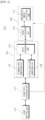
- FIG. 1 is a block diagram schematically illustrating a target object recognizing apparatus according to an exemplary embodiment of the present invention.
- a target object recognizing apparatus 100 includes a LiDAR emitting unit 110, a LiDAR data acquiring unit 120, a learning unit 130, and a recognizing unit 140.
- the target object recognizing apparatus 100 of FIG. 1 is an example so that all blocks illustrated in FIG. 1 are not essential components and in the other exemplary embodiment, some blocks included in the target object recognizing apparatus 100 may be added, modified, or omitted.
- the LiDAR emitting unit 110 converts an electrical signal into light and irradiates converted laser light to recognize a target object.
- the LiDAR emitting unit 110 may irradiate laser light to a reference target object or a new target object.
- the reference target object is a target object which becomes a reference for generating virtual LiDAR data with respect to a virtual target object and refers to a target object which has a spherical photoreceptor shape and can change various surface conditions, for example, various surface materials or surface colors.
- the new target object refers to a target object to be recognized after applying a weight determined based on a virtual LiDAR data based learning result and may be various types of objects.
- the LiDAR data acquiring unit 120 receives a reflection signal obtained by reflecting laser light from the target object and acquires LiDAR data generated based on the received reflection signal.
- the LiDAR data acquiring unit 120 acquires LiDAR data based on the reflection signal of the reference target object.
- the LiDAR data acquiring unit 120 acquires LiDAR data for a spherical photoreceptor type reference target object and acquires LiDAR data based on a reflectance of the reflection signal excluding a signal which is scattered from the spherical photoreceptor.
- the LiDAR data acquiring unit 120 may acquire LiDAR data for a plurality of reference target objects. That is, the LiDAR data acquiring unit 120 acquires LiDAR data for each of the plurality of reference target objects and changes a surface condition of the spherical receptor to sequentially acquire LiDAR data.
- the acquired LiDAR data may vary depending on the surface condition such as a surface material or a surface color of the spherical photoreceptor.
- the LiDAR data acquiring unit 120 acquires LiDAR data based on the reflection signal of the new target object.
- the acquired LiDAR data may be used for the recognizing unit 140 to recognize the new target object.
- the learning unit 130 performs an operation of determining a weight to recognize an operation by performing deep learning based on the LiDAR data.
- the learning unit 130 according to the exemplary embodiment may include a reference map generating unit 132, a virtual LiDAR data generating unit 134, and a data learning unit 136.
- the learning unit 130 generates a reference map and virtual LiDAR data based on the LiDAR data and performs the deep learning based on the virtual LiDAR data to determine a weight for recognizing a target object.
- the reference map generating unit 132 performs modeling based on range data and intensity data included in the LiDAR data to generate a reference map.
- the range data indicates a distance between the LiDAR emitting unit 110 and the target object and the intensity data is information indicating an intensity of the reflection signal (reflected light) obtained by reflecting emitted laser light from the target object and includes surface information of an object.
- the reference map generating unit 132 generates reference data by modeling a plurality of data included in the LiDAR data and generates a reference map in accordance with a surface condition of the reference target object based on the reference data.
- the reference map generating unit 132 may generate a reference map using reference data for every surface condition such as a surface material or a surface color of the reference target object.
- the reference map generating unit 132 may generate reference data by modeling all or some of the plurality of information included in the LiDAR data. For example, the reference map generating unit 132 may generate reference data by modeling at least one information of an angle ⁇ Beam between the LiDAR emitting unit 110 which irradiates laser light and the reference target object, a distance d Beam from the LiDAR emitting unit 110 to the surface of the reference target object, a distance d Sph from the LiDAR emitting unit 110 to a center of the reference target object, and a radius r Sph of the reference target object.
- the reference map generating unit 132 may adjust the reference data by assigning a weight for an accuracy or a usage frequency of each of the plurality of information included in the LiDAR data. For example, when a target object to be recognized by the target object recognizing apparatus 100 is specified or a category of a shape is determined, the reference map generating unit 132 assigns a weight calculated based on an accuracy or a usage frequency for recognizing the target object to each of the plurality of information included in the LiDAR data acquired by a spherical photoreceptor to generate or adjust reference data.
- the reference map generating unit 132 transmits reference data which is generated by applying a weight to the virtual LiDAR data generating unit 134 to generate weight based virtual LiDAR data.
- the virtual LiDAR data generating unit 134 performs an operation of generating virtual LiDAR data for a virtual target object based on the generated reference map.
- the virtual LiDAR data generating unit 134 may generate virtual LiDAR data using a plurality of reference data included in the reference map. That is, the virtual LiDAR data generating unit 134 may generate virtual LiDAR data by changing a combination of a plurality of reference data included in the reference map or a value of the reference data.
- the virtual LiDAR data generating unit 134 may be implemented by an encoder or a generator of a generative adversarial network (GAN) and generate a plurality of virtual LiDAR data by means of the encoder or the generator of the generative adversarial network (GAN).
- the virtual LiDAR data generated by means of the encoder and the generator may generate a plurality of virtual LiDAR data based on a feature value of each reference data with the plurality of reference data included in the reference map as an input.
- the data learning unit 136 performs an operation of determining a weight for recognizing a target object using virtual LiDAR data.
- the data learning unit 136 performs deep learning based on the virtual LiDAR data and determines a weight based on the learning result.
- the data learning unit 136 has been described to perform the learning only using the virtual LiDAR data, but is not necessarily limited thereto.
- the data learning unit 136 performs deep learning based on the virtual LiDAR data and LiDAR data for the reference target object and determines a weight based on the learning result.
- the data learning unit 136 combines all or a part of the LiDAR data for the reference target object with the virtual LiDAR data to perform the deep learning.
- the weight which is determined based on the learning result is a weight which is applied to an operation recognizing algorithm used to recognize an operation of the target object and may be a weight which is applied to a convolution layer or a hidden layer included in the operation recognizing algorithm.
- the recognizing unit 140 performs an operation of recognizing a target object by applying a weight determined according to the learning result and calculating a recognition result.
- the recognizing unit 140 may include a target recognizing unit 142 and a recognition result calculating unit 144.
- the recognizing unit 140 When new LiDAR data for the new target object is acquired, the recognizing unit 140 performs an operation of recognizing the new target object by applying a weight.
- the target recognizing unit 142 performs an operation of analyzing new LiDAR data by applying a weight determined based on the learning result to recognize a new target object.
- the recognition result calculating unit 144 performs an operation of calculating position information of the recognized new target object.
- FIG. 2 is a flowchart for explaining a target object recognizing method according to an exemplary embodiment of the present invention.
- the target object recognizing apparatus 100 emits laser light to the reference target object and acquires LiDAR data based on a reflection signal reflected from the reference target object in step S210.
- the target object recognizing apparatus 100 acquires LiDAR data for a spherical photoreceptor type reference target object and acquires LiDAR data based on a reflectance of the reflection signal excluding a signal which is scattered from the spherical photoreceptor.
- the acquired LiDAR data may vary depending on the surface condition such as a surface material or a surface color of the spherical receptor.
- the target object recognizing apparatus 100 generate a reference map based on range data and intensity data generated by modeling based on the acquired LiDAR data in step S220. Specifically, the target object recognizing apparatus 100 generates reference data by modeling range data and intensity data included in the LiDAR data and generates a reference map in accordance with a surface condition of the reference target object based on the reference data.
- the target object recognizing apparatus 100 may generate a reference map using reference data for every surface condition such as a surface material or a surface color of the reference target object.
- the target object recognizing apparatus 100 generates virtual LiDAR data for a virtual target object based on the generated reference map in step S230.
- the target object recognizing apparatus 100 may generate virtual LiDAR data by changing a combination of a plurality of reference data included in the reference map or a value of the reference data.
- the target object recognizing apparatus 100 performs deep learning based on the virtual LiDAR data and determines a weight based on the learning result in step S240.
- the target object recognizing apparatus 100 has been described to determine a weight only using the virtual LiDAR data, but is not necessarily limited thereto.
- the target object recognizing apparatus 100 performs deep learning by mixing virtual LiDAR data and LiDAR data (actual LiDAR data) with respect to the reference target object and determines a weight based on the learning result.
- the target object recognizing apparatus 100 applies a determined weight to recognize a target object in step S250.
- the target object recognizing apparatus 100 calculates position information of the recognized target object to generate a target recognition result in step S260.
- FIG. 2 it is described that the steps are sequentially performed, the present invention is not necessarily limited thereto. In other words, the steps illustrated in FIG. 2 may be changed or one or more steps may be performed in parallel so that FIG. 2 is not limited to a time-series order.
- the target object recognizing method according to the exemplary embodiment described in FIG. 2 may be implemented by an application (or a program) and may be recorded in a terminal (or computer) readable recording media.
- the recording medium which has the application (or program) for implementing the target object recognizing method according to the exemplary embodiment recorded therein and is readable by the terminal device (or a computer) includes all kinds of recording devices or media in which computing system readable data is stored.
- FIG. 3 is a view for explaining an operation of acquiring and modeling LiDAR data for recognizing a target object according to an exemplary embodiment of the present invention.
- the target object recognizing apparatus 100 irradiates laser light to the reference target object 300 by means of the laser emitting unit 110 and receives a reflection signal 302 reflected from the reference target object 300 to acquire LiDAR data.
- the target object recognizing apparatus 100 acquires LiDAR data using a spherical receptor as the reference target object 300 so as to minimize an error of acquired data caused according to an appearance of the target object.
- the target object recognizing apparatus 100 may acquire LiDAR data including range data and intensity data based on a reflectance of the reflection signal 302 excluding a signal 304 scattered from the reference target object 300.
- the target object recognizing apparatus 100 acquires LiDAR data including a range, surface information, a direction, a speed, a temperature, a material distribution of a surface, and a concentration characteristic by measuring a time to receive the irradiated laser light, which is reflected from the reference target object 300, as a reflection signal 302, and intensity.
- the target object recognizing apparatus 100 may acquire LiDAR data including angles ⁇ Beam 306 and 308 between the LiDAR emitting unit 110 which irradiates laser light and the reference target object 300, a distance d Beam 320 from the LiDAR emitting unit 110 to the surface of the reference target object 300, a distance d Sph 330 from the LiDAR emitting unit 110 to a center of the reference target object 300, and a radius r Sph 310 of the reference target object 300, using the reflection signal 302.
- the target object recognizing apparatus 100 may generate reference data i reflect by modeling the range data and the intensity data included in the LiDAR data.
- the modeled reference data i reflect may be defined by Equation 1.
- f r Sph , d Sph , d Beam , ⁇ Beam i reflect (f(x): predetermined modeling function, r Sph : radius of reference target object 300, d Sph : distance from LiDAR emitting unit 110 to center of reference target object 300, d Beam : distance from LiDAR emitting unit 110 to surface of reference target object 300, ⁇ Beam : angle between LiDAR emitting unit 110 and reference target object 300)
- the target object recognizing apparatus 100 generates reference data for every surface condition of the reference target object 300 to generate a reference map.
- the target object recognizing apparatus 100 may generate a reference map using reference data for every surface condition such as a surface material or a surface color of the reference target object 300.
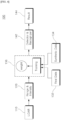
- FIG. 4 is a block diagram schematically illustrating a target object recognizing apparatus according to another exemplary embodiment of the present invention.
- the target object recognizing apparatus 100 irradiates laser light to the reference target object 300 and receives a reflection signal 302 reflected from the reference target object 300 to acquire LiDAR data.
- the target object recognizing apparatus 100 acquires LiDAR data using a spherical receptor as the reference target object 300 so as to minimize an error of acquired data caused according to an appearance of the target object (block 110).
- the target object recognizing apparatus 100 generates reference data i reflect by modeling the range data and the intensity data for every surface condition such as a material (for example, a fabric, a metal, or a wood) or a color of the reference target object 300 using the acquired LiDAR data.
- the range data and the intensity data are simultaneously acquired from the LiDAR and the range data indicates a distance from the LiDAR emitting unit 110 to the surface of the reference target object 300 and the intensity data is information indicating the intensity of the reflection signal of the emitted laser light reflected from the target object and provides surface data of the target object.
- the target object recognizing apparatus 100 may extract LiDAR data with respect to an actual target object based on the reference data.
- the target object recognizing apparatus 100 has been described to extract actual LiDAR data based on the reference data, but is not necessarily limited thereto and the LiDAR data may be acquired based on a reflection signal which is received by irradiating laser light.
- the target object recognizing apparatus 100 generates virtual LiDAR data for the virtual target object. Specifically, the target object recognizing apparatus 100 generates virtual LiDAR data with respect to a virtual target object existing in a virtual space using reference data which is modeled using the reference target object 300.
- the virtual LiDAR data may include virtual range data and virtual intensity data.
- the target object recognizing apparatus 100 performs an operation of determining a weight for recognizing a target object using virtual LiDAR data.
- the target object recognizing apparatus 100 performs deep learning based on the virtual LiDAR data and determines a weight based on the learning result.
- the target object recognizing apparatus 100 has been described to perform learning only using the virtual LiDAR data, but is not necessarily limited thereto.
- the target object recognizing apparatus 100 performs deep learning based on the virtual LiDAR data and LiDAR data for the reference target object and determines a weight based on the learning result.
- the target object recognizing apparatus 100 combines all or a part of the LiDAR data with respect to the reference target object with the virtual LiDAR data to perform the deep learning.
- the target object recognizing apparatus 100 performs an operation of applying the weight determined according to the learning result learned in block 136 to recognize a target object and calculating a recognition result.
- the target object recognizing apparatus 100 recognizes the new target object by applying the learning result which is learned in advance and calculates position information of the new target object using the range data and the intensity data of the new LiDAR data.
- FIG. 5 is a block diagram schematically illustrating a target object recognizing apparatus according to still another exemplary embodiment of the present invention.
- the target object recognizing apparatus 500 may include a transmitting unit 510, a receiving unit 520, a processor 530, a memory 540, and a database 550.
- the target object recognizing apparatus 500 of FIG. 5 is an example so that all blocks illustrated in FIG. 5 are not essential components and in the other exemplary embodiment, some blocks included in the target object recognizing apparatus 500 may be added, modified, or omitted.
- the target object recognizing apparatus 500 may be implemented by a computing device and each component included in the target object recognizing apparatus 500 may be implemented by a separate software device or a separate hardware device in which the software is combined.
- the target object recognizing apparatus 500 emits laser light to the reference target object and acquires LiDAR data generated based on a reflection signal reflected from the reference target object.
- the target object recognizing apparatus 500 performs an operation of generating a reference map and virtual LiDAR data based on the LiDAR data and performing the deep learning based on the virtual LiDAR data to determine a weight for recognizing a target object.
- the target object recognizing apparatus 500 performs an operation of recognizing the new target object by applying a weight.
- the transmitting unit 510 may generate and output a transmission signal.
- the transmitting unit 510 is controlled by the processor 530.
- the transmitting unit 510 may output a transmission signal in the form of laser light.
- the transmitting unit 510 converts an electrical signal into light and includes a laser generating unit (not illustrated).
- the transmitting unit 510 outputs a transmission signal in the form of a frequency modulated continuous wave (FMCW).
- FMCW frequency modulated continuous wave
- the transmitting unit 510 may perform beam steering with respect to the generated laser light.
- the transmitting unit 510 may perform the beam steering by changing a path of the laser light.
- the receiving unit 520 acquires a reception signal.
- the reception signal is a reflection signal obtained by reflecting the transmission signal from the target object.
- the receiving unit 520 is controlled by the processor 530.
- the receiving unit 520 may acquire a reception signal corresponding to FMCW.
- the receiving unit 520 may include a photo detector (not illustrated).
- the photo detector may convert light into electricity and may be implemented by including a plurality of photo diodes PD.
- the receiving unit 520 may receive a reflection signal at each point of transmitted laser light. For example, when the laser light is output toward a first point, the receiving unit 520 may receive a reception signal which returns from the first point. Further, when the laser light is output toward a second point, the receiving unit 520 may receive a reception signal which returns from the second point. As described above, the receiving unit 520 receives reflections signals which return from a plurality of continuous points to sense a reflection signal at each point.
- the processor 530 performs a function of executing at least one instruction or program included in the memory 540.
- the processor 530 performs an operation of performing learning based on LiDAR data acquired using the transmitting unit 510 and the receiving unit 520.
- the processor 530 performs modeling based on the acquired LiDAR data to generate a reference map based on range data and intensity data. Specifically, the processor 530 generates reference data by modeling range data and intensity data included in the LiDAR data and generates a reference map in accordance with a surface condition of the reference target object based on the reference data. Here, the processor 530 may generate a reference map using reference data for every surface condition such as a surface material or a surface color of the reference target object.
- the processor 530 generates virtual LiDAR data for a virtual target object based on the generated reference map.
- the processor 530 may generate virtual LiDAR data by changing a combination of a plurality of reference data included in the reference map or a value of the reference data.
- the processor 530 performs deep learning based on the virtual LiDAR data and determines a weight based on the learning result.
- the processor 530 has been described to determine a weight only using the virtual LiDAR data, but is not necessarily limited thereto.
- the processor 530 performs deep learning by mixing virtual LiDAR data and LiDAR data (actual LiDAR data) with respect to the reference target object and determines a weight based on the learning result.
- the processor 530 may perform an operation of recognizing a target object based on the weight determined by the learning.
- the processor 530 When new LiDAR data with respect to the target object is acquired using the transmitting unit 510 and the receiving unit 520, the processor 530 recognizes a target object by applying a weight determined based on the learning result. The processor 530 generates a target recognition result by calculating position information with respect to the recognized target object.
- the memory 540 includes at least one instruction or program which is executable by the processor 530.
- the memory 540 may include an instruction or a program for a data acquiring operation, a modeling operation, a virtual LiDAR data generating operation, and a learning operation. Further, the memory 540 may include an instruction or a program for an operation of applying a learning result and an operation of recognizing a target object.
- the memory 540 may be various hardware storage units such as a ROM, a RAM, an EEPROM, a flash drive, and a hard drive.
- the database 150 refers to a general data structure implemented in a storage space (a hard disk or a memory) of a computer system using a database management program (DBMS) and means a data storage format which freely searches (extracts), deletes, edits, or adds data.
- the database 150 may be implemented according to the object of the exemplary embodiment of the present invention using a relational database management system (RDBMS) such as Oracle, Informix, Sybase, or DB2, an object oriented database management system (OODBMS) such as Gemston, Orion, or 02, and XML native database such as Excelon, Tamino, Sekaiju and has an appropriate field or elements to achieve its own function.
- RDBMS relational database management system
- OODBMS object oriented database management system
- the database 150 may store data related to the recognition of the target object and provide data related to the recognition of previously stored target object.
- the data stored in database 150 may include data such as LiDAR data with respect to the reference target object, virtual LiDAR data, reference data, a reference map, a learning result, a weight, a target object recognition result, and position information of the target object. It has been described that the database 250 is implemented in the target object recognizing apparatus 100, but is not necessarily limited thereto and may be implemented as a separate data storage device.
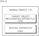
- FIG. 6 is a block diagram schematically illustrating a mobile object using a target object recognizing apparatus according to an exemplary embodiment of the present invention.
- a mobile object 1 includes a target object recognizing apparatus 100 and a moving apparatus 200.
- the mobile object 10 may omit some components among various components which are exemplarily illustrated in FIG. 6 or may further include other component.
- the mobile object may further include a cleaning unit.
- the mobile object 10 may include a target object recognizing apparatus 100 which acquires LiDAR data based on a reflection signal obtained by reflecting laser light irradiated onto the target object and calculates position information of the target object by applying a previously trained learning result and a moving apparatus 200 which moves the mobile object 10 based on the position of the target object.
- the target object recognizing apparatus 100 calculates position information of the target object based on LiDAR data of the target object by applying a weight determined based on the learning result by means of the reference target object to move the mobile object 10.
- the moving apparatus 200 included in the mobile object 10 refers to a device designed to be movable from a specific location to another location according to a predetermined method and moves from the specific location to another location using a moving unit such as wheels, rails, walking legs, wings, or a multi rotor.
- the moving object 10 may collect external information using the target object recognizing apparatus 100 and then move according to the collected information or move using a separate manipulating unit by a user.
- Examples of the moving object 10 include robot cleaners, toy cars, and mobile robots for industrial or military purposes.
- the robot cleaner is a device which sucks foreign materials such as dust accumulated on a floor while traveling a cleaning space to automatically clean the cleaning space. Differently from a normal cleaner which moves by an external force provided by a user, the robot cleaner cleans the cleaning space while moving using external information or a predetermined moving pattern.
- the robot cleaner may automatically move using a predetermined pattern or detect external obstacles using a detecting sensor and then moves as it is detected. Further, the robot cleaner may move in accordance with a signal transmitted from a remote control device which is manipulated by the user.
- a detecting sensor of the target object recognizing apparatus 100 may be implemented by a LiDAR (Light detection and ranging).
- the LiDAR is a device which transmits laser light, measures a time and an intensity of a reflection signal which is reflected to return, and measures a distance and a surface information of a reflector using a speed of light.
- the reflection signal is converted into an electrical signal by the photo diode and has a predetermined wavelength band.
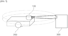
- FIG. 7 is an exemplary view illustrating a mobile object according to an exemplary embodiment of the present invention.
- the target object recognizing apparatus 100 which measures range and surface information of the target object 300 by acquiring LiDAR data including range data and intensity data based on a reflection signal of the laser light between the mobile object 10 and the target object 300 is located at an upper portion of the main body, it is just illustrative. Therefore, the present invention is not limited thereto and one or more target object recognizing apparatuses may be implemented in an appropriate position according to a design to be implemented.
- the target object recognizing apparatus 100 transmits and receives light using a pair of light sources and a photo diode and three-dimensionally scans surroundings using a movable mirror and a rotor.
- the target object recognizing apparatus 100 may operate by a time of flight (TOF) manner.
- TOF time of flight
- a laser emits a pulsed or square wave signal to measure a time when reflection pulses or square wave signals from objects within a measurement range reach a receiver to measure a distance between an object to be measured and the target object recognizing apparatus 100.
- the moving apparatus 200 calculates a traveling route based on a distance to the target object or detects an obstacle to move the mobile object 10.
- the moving apparatus 200 may move the mobile object 10 based on a relative location of an artificial mark.
- Target object recognizing apparatus 110 LiDAR emitting unit 120: LiDAR data acquiring unit 130: Learning unit 132: Reference map generating unit 134: Virtual LiDAR data generating unit 136: Data learning unit 140: Recognizing unit 142: Target recognizing unit 144: Recognized result calculating unit
Landscapes
- Engineering & Computer Science (AREA)
- Physics & Mathematics (AREA)
- General Physics & Mathematics (AREA)
- Theoretical Computer Science (AREA)
- Computer Networks & Wireless Communication (AREA)
- Radar, Positioning & Navigation (AREA)
- Remote Sensing (AREA)
- Electromagnetism (AREA)
- Computational Linguistics (AREA)
- General Health & Medical Sciences (AREA)
- Biomedical Technology (AREA)
- Biophysics (AREA)
- Life Sciences & Earth Sciences (AREA)
- Data Mining & Analysis (AREA)
- Evolutionary Computation (AREA)
- Artificial Intelligence (AREA)
- Molecular Biology (AREA)
- Computing Systems (AREA)
- General Engineering & Computer Science (AREA)
- Mathematical Physics (AREA)
- Software Systems (AREA)
- Health & Medical Sciences (AREA)
- Probability & Statistics with Applications (AREA)
- Optical Radar Systems And Details Thereof (AREA)
Abstract
Description
- The present invention relates to a 3D LiDAR based target object recognizing method, apparatus, and a mobile object using the same.
- The contents described in this section merely provide background information on the exemplary embodiment of the present disclosure, but do not constitute the related art.
- In accordance with the development of the IT technology, studies for 3D sensing and data processing of a space and an object in an artificial intelligence field are being actively conducted. A sensing method using a 3D LiDAR provides data with respect to a range and an intensity. In the 3D LiDAR sensing method, the intensity data provides information about a surface of a target object so that it is very useful to classify and identify an object.
- In the field of 3D sensing and data processing, a deep learning based artificial intelligence requires a large amount of data in various environments. However, it is difficult to collect data for the range and the intensity for various environments and materials of the object in an actual environment.
- Accordingly, a data securing method for implementing a deep learning based artificial intelligence for 3D sensing and data processing and improving a performance is necessary.
- A major object of the present invention is to provide a 3D LiDAR based target object recognizing method and apparatus which generate a reference map based on LiDAR data for a reference target object, determines a weight by learning virtual LiDAR data generated based on the reference map, and recognize a new target object by applying a determined weight, and a mobile object using the same.
- According to an aspect of the present invention, in order to achieve the above-described object, a target object recognizing method includes an irradiating step of irradiating laser light to a reference target object; an acquiring step of acquiring LiDAR data generated based on a reflection signal reflected from the reference target object; a learning step of generating a reference map and virtual LiDAR data based on the LiDAR data and determining a weight for recognizing a target object by performing the deep learning based on the virtual LiDAR data; and a recognizing step of recognizing a new target object by applying the weight when new LiDAR data with respect to the new target object is acquired.
- According to another aspect of the present disclosure, in order to achieve the above-described object, a target object recognizing apparatus includes: a transmitting unit which irradiates laser light; a receiving unit which receives a reflection signal with respect to the laser light; one or more processors; and a memory in which one or more programs executed by the processors are stored, when the programs are executed by one or more processors, the programs allow one or more processors to perform operations including: an acquiring step of acquiring LiDAR data generated based on a reflection signal obtained by reflecting the irradiated laser light from the reference target object; a learning step of generating a reference map and virtual LiDAR data based on the LiDAR data and determining a weight for recognizing a target object by performing the deep learning based on the virtual LiDAR data; and a recognizing step of recognizing a new target object by applying the weight when new LiDAR data with respect to the new target object is acquired.
- According to another aspect of the present disclosure, in order to achieve the above-described object, a mobile object includes: a target object recognizing apparatus which irradiates laser light, acquires LiDAR data based on a reflection signal obtained by reflecting the laser light, and calculates position information of the target object by applying a previously learned learning result; and a moving apparatus which moves the mobile object based on a position of the target object, and the target object recognizing apparatus calculates position information of the target object based on LiDAR data of the target object by applying a weight determined based on the learning result by means of a reference target object to move the mobile object.
- As described above, according to the present invention, LiDAR data can be collected without causing errors by acquiring data using a spherical photoreceptor type reference target object and LiDAR data for various shapes and materials can be collected.
- Further, according to the present invention, LiDAR data for virtual target objects having various shapes and materials may be generated.
- Further, according to the present invention, a large amount of data, for 3D LiDAR sensing, to which diversity (materials, shapes, and colors) of the same material is reflected may be ensured using the generated virtual LiDAR data.
- Further, according to the present invention, a recognizing performance of a target material may be improved by deep learning based on a large amount of various LiDAR data.
-
-
FIG. 1 is a block diagram schematically illustrating a target object recognizing apparatus according to an exemplary embodiment of the present invention. -
FIG. 2 is a flowchart for explaining a target object recognizing method according to an exemplary embodiment of the present invention. -
FIG. 3 is a view for explaining an operation of acquiring and modeling LiDAR data for recognizing a target object according to an exemplary embodiment of the present invention. -
FIG. 4 is a block diagram schematically illustrating a target object recognizing apparatus according to another exemplary embodiment of the present invention. -
FIG. 5 is a block diagram schematically illustrating a target object recognizing apparatus according to still another exemplary embodiment of the present invention. -
FIG. 6 is a block diagram schematically illustrating a mobile object using a target object recognizing apparatus according to an exemplary embodiment of the present invention. -
FIG. 7 is an exemplary view illustrating a mobile object according to an exemplary embodiment of the present invention. - Hereinafter, exemplary embodiments of the present invention will be described in detail with reference to the accompanying drawings. If it is considered that the specific description of related known configuration or function may cloud the gist of the present invention, the detailed description will be omitted. Further, hereinafter, exemplary embodiments of the present invention will be described. However, it should be understood that the technical spirit of the invention is not limited to the specific embodiments, but may be changed or modified in various ways by those skilled in the art. Hereinafter, a 3D LiDAR based target object recognizing method, apparatus, and a mobile object using the same proposed by the present invention will be described in detail with reference to the drawings.
-
FIG. 1 is a block diagram schematically illustrating a target object recognizing apparatus according to an exemplary embodiment of the present invention. - A target
object recognizing apparatus 100 according to the exemplary embodiment includes a LiDARemitting unit 110, a LiDARdata acquiring unit 120, alearning unit 130, and a recognizingunit 140. The targetobject recognizing apparatus 100 ofFIG. 1 is an example so that all blocks illustrated inFIG. 1 are not essential components and in the other exemplary embodiment, some blocks included in the targetobject recognizing apparatus 100 may be added, modified, or omitted. - The LiDAR
emitting unit 110 converts an electrical signal into light and irradiates converted laser light to recognize a target object. - The LiDAR
emitting unit 110 may irradiate laser light to a reference target object or a new target object. Here, the reference target object is a target object which becomes a reference for generating virtual LiDAR data with respect to a virtual target object and refers to a target object which has a spherical photoreceptor shape and can change various surface conditions, for example, various surface materials or surface colors. Further, the new target object refers to a target object to be recognized after applying a weight determined based on a virtual LiDAR data based learning result and may be various types of objects. - The LiDAR
data acquiring unit 120 receives a reflection signal obtained by reflecting laser light from the target object and acquires LiDAR data generated based on the received reflection signal. - During the process of performing learning for recognizing a target object, the LiDAR
data acquiring unit 120 acquires LiDAR data based on the reflection signal of the reference target object. The LiDARdata acquiring unit 120 acquires LiDAR data for a spherical photoreceptor type reference target object and acquires LiDAR data based on a reflectance of the reflection signal excluding a signal which is scattered from the spherical photoreceptor. - The LiDAR
data acquiring unit 120 may acquire LiDAR data for a plurality of reference target objects. That is, the LiDARdata acquiring unit 120 acquires LiDAR data for each of the plurality of reference target objects and changes a surface condition of the spherical receptor to sequentially acquire LiDAR data. Here, the acquired LiDAR data may vary depending on the surface condition such as a surface material or a surface color of the spherical photoreceptor. - In the meantime, when the process of performing learning for recognizing a target object is completed, the LiDAR
data acquiring unit 120 acquires LiDAR data based on the reflection signal of the new target object. Here, the acquired LiDAR data may be used for the recognizingunit 140 to recognize the new target object. - The
learning unit 130 according to the exemplary embodiment performs an operation of determining a weight to recognize an operation by performing deep learning based on the LiDAR data. Thelearning unit 130 according to the exemplary embodiment may include a referencemap generating unit 132, a virtual LiDARdata generating unit 134, and adata learning unit 136. - The
learning unit 130 generates a reference map and virtual LiDAR data based on the LiDAR data and performs the deep learning based on the virtual LiDAR data to determine a weight for recognizing a target object. - The reference
map generating unit 132 performs modeling based on range data and intensity data included in the LiDAR data to generate a reference map. Here, the range data indicates a distance between the LiDARemitting unit 110 and the target object and the intensity data is information indicating an intensity of the reflection signal (reflected light) obtained by reflecting emitted laser light from the target object and includes surface information of an object. - Specifically, the reference
map generating unit 132 generates reference data by modeling a plurality of data included in the LiDAR data and generates a reference map in accordance with a surface condition of the reference target object based on the reference data. - The reference
map generating unit 132 may generate a reference map using reference data for every surface condition such as a surface material or a surface color of the reference target object. - The reference
map generating unit 132 may generate reference data by modeling all or some of the plurality of information included in the LiDAR data. For example, the referencemap generating unit 132 may generate reference data by modeling at least one information of an angle ΘBeam between the LiDARemitting unit 110 which irradiates laser light and the reference target object, a distance dBeam from the LiDARemitting unit 110 to the surface of the reference target object, a distance dSph from the LiDARemitting unit 110 to a center of the reference target object, and a radius rSph of the reference target object. - In the meantime, the reference
map generating unit 132 may adjust the reference data by assigning a weight for an accuracy or a usage frequency of each of the plurality of information included in the LiDAR data. For example, when a target object to be recognized by the targetobject recognizing apparatus 100 is specified or a category of a shape is determined, the referencemap generating unit 132 assigns a weight calculated based on an accuracy or a usage frequency for recognizing the target object to each of the plurality of information included in the LiDAR data acquired by a spherical photoreceptor to generate or adjust reference data. The referencemap generating unit 132 transmits reference data which is generated by applying a weight to the virtual LiDARdata generating unit 134 to generate weight based virtual LiDAR data. - The virtual LiDAR
data generating unit 134 performs an operation of generating virtual LiDAR data for a virtual target object based on the generated reference map. - The virtual LiDAR
data generating unit 134 may generate virtual LiDAR data using a plurality of reference data included in the reference map. That is, the virtual LiDARdata generating unit 134 may generate virtual LiDAR data by changing a combination of a plurality of reference data included in the reference map or a value of the reference data. - In the meantime, the virtual LiDAR
data generating unit 134 may be implemented by an encoder or a generator of a generative adversarial network (GAN) and generate a plurality of virtual LiDAR data by means of the encoder or the generator of the generative adversarial network (GAN). Here, the virtual LiDAR data generated by means of the encoder and the generator may generate a plurality of virtual LiDAR data based on a feature value of each reference data with the plurality of reference data included in the reference map as an input. - The
data learning unit 136 performs an operation of determining a weight for recognizing a target object using virtual LiDAR data. - The
data learning unit 136 performs deep learning based on the virtual LiDAR data and determines a weight based on the learning result. In the meantime, thedata learning unit 136 has been described to perform the learning only using the virtual LiDAR data, but is not necessarily limited thereto. For example, thedata learning unit 136 performs deep learning based on the virtual LiDAR data and LiDAR data for the reference target object and determines a weight based on the learning result. Here, thedata learning unit 136 combines all or a part of the LiDAR data for the reference target object with the virtual LiDAR data to perform the deep learning. Here, the weight which is determined based on the learning result is a weight which is applied to an operation recognizing algorithm used to recognize an operation of the target object and may be a weight which is applied to a convolution layer or a hidden layer included in the operation recognizing algorithm. - The recognizing
unit 140 performs an operation of recognizing a target object by applying a weight determined according to the learning result and calculating a recognition result. The recognizingunit 140 according to the exemplary embodiment may include atarget recognizing unit 142 and a recognitionresult calculating unit 144. - When new LiDAR data for the new target object is acquired, the recognizing
unit 140 performs an operation of recognizing the new target object by applying a weight. - The
target recognizing unit 142 performs an operation of analyzing new LiDAR data by applying a weight determined based on the learning result to recognize a new target object. - The recognition
result calculating unit 144 performs an operation of calculating position information of the recognized new target object. -
FIG. 2 is a flowchart for explaining a target object recognizing method according to an exemplary embodiment of the present invention. - The target
object recognizing apparatus 100 emits laser light to the reference target object and acquires LiDAR data based on a reflection signal reflected from the reference target object in step S210. - The target
object recognizing apparatus 100 acquires LiDAR data for a spherical photoreceptor type reference target object and acquires LiDAR data based on a reflectance of the reflection signal excluding a signal which is scattered from the spherical photoreceptor. Here, the acquired LiDAR data may vary depending on the surface condition such as a surface material or a surface color of the spherical receptor. - Hereinafter, an operation of performing learning based on the acquired LiDAR data by the target
object recognizing apparatus 100 will be described. - The target
object recognizing apparatus 100 generate a reference map based on range data and intensity data generated by modeling based on the acquired LiDAR data in step S220. Specifically, the targetobject recognizing apparatus 100 generates reference data by modeling range data and intensity data included in the LiDAR data and generates a reference map in accordance with a surface condition of the reference target object based on the reference data. Here, the targetobject recognizing apparatus 100 may generate a reference map using reference data for every surface condition such as a surface material or a surface color of the reference target object. - The target
object recognizing apparatus 100 generates virtual LiDAR data for a virtual target object based on the generated reference map in step S230. The targetobject recognizing apparatus 100 may generate virtual LiDAR data by changing a combination of a plurality of reference data included in the reference map or a value of the reference data. - The target
object recognizing apparatus 100 performs deep learning based on the virtual LiDAR data and determines a weight based on the learning result in step S240. Here, the targetobject recognizing apparatus 100 has been described to determine a weight only using the virtual LiDAR data, but is not necessarily limited thereto. The targetobject recognizing apparatus 100 performs deep learning by mixing virtual LiDAR data and LiDAR data (actual LiDAR data) with respect to the reference target object and determines a weight based on the learning result. - Hereinafter, an operation of recognizing a target object based on a weight determined by means of the learning by the target
object recognizing apparatus 100 will be described. - When new LiDAR data for a target object is acquired, the target
object recognizing apparatus 100 applies a determined weight to recognize a target object in step S250. - The target
object recognizing apparatus 100 calculates position information of the recognized target object to generate a target recognition result in step S260. - Even though in
FIG. 2 , it is described that the steps are sequentially performed, the present invention is not necessarily limited thereto. In other words, the steps illustrated inFIG. 2 may be changed or one or more steps may be performed in parallel so thatFIG. 2 is not limited to a time-series order. - The target object recognizing method according to the exemplary embodiment described in
FIG. 2 may be implemented by an application (or a program) and may be recorded in a terminal (or computer) readable recording media. The recording medium which has the application (or program) for implementing the target object recognizing method according to the exemplary embodiment recorded therein and is readable by the terminal device (or a computer) includes all kinds of recording devices or media in which computing system readable data is stored. -
FIG. 3 is a view for explaining an operation of acquiring and modeling LiDAR data for recognizing a target object according to an exemplary embodiment of the present invention. - The target
object recognizing apparatus 100 irradiates laser light to thereference target object 300 by means of thelaser emitting unit 110 and receives areflection signal 302 reflected from thereference target object 300 to acquire LiDAR data. Here, the targetobject recognizing apparatus 100 acquires LiDAR data using a spherical receptor as thereference target object 300 so as to minimize an error of acquired data caused according to an appearance of the target object. - The target
object recognizing apparatus 100 may acquire LiDAR data including range data and intensity data based on a reflectance of thereflection signal 302 excluding asignal 304 scattered from thereference target object 300. Here, the targetobject recognizing apparatus 100 acquires LiDAR data including a range, surface information, a direction, a speed, a temperature, a material distribution of a surface, and a concentration characteristic by measuring a time to receive the irradiated laser light, which is reflected from thereference target object 300, as areflection signal 302, and intensity. For example, the targetobject recognizing apparatus 100 may acquire LiDAR data including angles ΘBeam 306 and 308 between theLiDAR emitting unit 110 which irradiates laser light and thereference target object 300, adistance d Beam 320 from theLiDAR emitting unit 110 to the surface of thereference target object 300, adistance d Sph 330 from theLiDAR emitting unit 110 to a center of thereference target object 300, and aradius r Sph 310 of thereference target object 300, using thereflection signal 302. - Further, the target
object recognizing apparatus 100 may generate reference data ireflect by modeling the range data and the intensity data included in the LiDAR data. Here, the modeled reference data ireflect may be defined by Equation 1.
reference target object 300, dSph: distance fromLiDAR emitting unit 110 to center ofreference target object 300, dBeam : distance fromLiDAR emitting unit 110 to surface ofreference target object 300, θBeam: angle betweenLiDAR emitting unit 110 and reference target object 300) - The target
object recognizing apparatus 100 generates reference data for every surface condition of thereference target object 300 to generate a reference map. Here, the targetobject recognizing apparatus 100 may generate a reference map using reference data for every surface condition such as a surface material or a surface color of thereference target object 300. -
FIG. 4 is a block diagram schematically illustrating a target object recognizing apparatus according to another exemplary embodiment of the present invention. - In
block 110, the targetobject recognizing apparatus 100 irradiates laser light to thereference target object 300 and receives areflection signal 302 reflected from thereference target object 300 to acquire LiDAR data. Here, the targetobject recognizing apparatus 100 acquires LiDAR data using a spherical receptor as thereference target object 300 so as to minimize an error of acquired data caused according to an appearance of the target object (block 110). - In
block 120, the targetobject recognizing apparatus 100 generates reference data ireflect by modeling the range data and the intensity data for every surface condition such as a material (for example, a fabric, a metal, or a wood) or a color of thereference target object 300 using the acquired LiDAR data. The range data and the intensity data are simultaneously acquired from the LiDAR and the range data indicates a distance from theLiDAR emitting unit 110 to the surface of thereference target object 300 and the intensity data is information indicating the intensity of the reflection signal of the emitted laser light reflected from the target object and provides surface data of the target object. - In
block 132, the targetobject recognizing apparatus 100 may extract LiDAR data with respect to an actual target object based on the reference data. Here, the targetobject recognizing apparatus 100 has been described to extract actual LiDAR data based on the reference data, but is not necessarily limited thereto and the LiDAR data may be acquired based on a reflection signal which is received by irradiating laser light. - In
block 134, the targetobject recognizing apparatus 100 generates virtual LiDAR data for the virtual target object. Specifically, the targetobject recognizing apparatus 100 generates virtual LiDAR data with respect to a virtual target object existing in a virtual space using reference data which is modeled using thereference target object 300. Here, the virtual LiDAR data may include virtual range data and virtual intensity data. - In
block 136, the targetobject recognizing apparatus 100 performs an operation of determining a weight for recognizing a target object using virtual LiDAR data. - Specifically, the target
object recognizing apparatus 100 performs deep learning based on the virtual LiDAR data and determines a weight based on the learning result. In the meantime, the targetobject recognizing apparatus 100 has been described to perform learning only using the virtual LiDAR data, but is not necessarily limited thereto. For example, the targetobject recognizing apparatus 100 performs deep learning based on the virtual LiDAR data and LiDAR data for the reference target object and determines a weight based on the learning result. Here, the targetobject recognizing apparatus 100 combines all or a part of the LiDAR data with respect to the reference target object with the virtual LiDAR data to perform the deep learning. - In blocks 142 and 144, the target
object recognizing apparatus 100 performs an operation of applying the weight determined according to the learning result learned inblock 136 to recognize a target object and calculating a recognition result. - When new LiDAR data with respect to a new target object is acquired, the target
object recognizing apparatus 100 recognizes the new target object by applying the learning result which is learned in advance and calculates position information of the new target object using the range data and the intensity data of the new LiDAR data. -
FIG. 5 is a block diagram schematically illustrating a target object recognizing apparatus according to still another exemplary embodiment of the present invention. - The target
object recognizing apparatus 500 according to the exemplary embodiment may include a transmittingunit 510, a receivingunit 520, aprocessor 530, amemory 540, and adatabase 550. The targetobject recognizing apparatus 500 ofFIG. 5 is an example so that all blocks illustrated inFIG. 5 are not essential components and in the other exemplary embodiment, some blocks included in the targetobject recognizing apparatus 500 may be added, modified, or omitted. In the meantime, the targetobject recognizing apparatus 500 may be implemented by a computing device and each component included in the targetobject recognizing apparatus 500 may be implemented by a separate software device or a separate hardware device in which the software is combined. - The target
object recognizing apparatus 500 emits laser light to the reference target object and acquires LiDAR data generated based on a reflection signal reflected from the reference target object. The targetobject recognizing apparatus 500 performs an operation of generating a reference map and virtual LiDAR data based on the LiDAR data and performing the deep learning based on the virtual LiDAR data to determine a weight for recognizing a target object. When new LiDAR data for the new target object is acquired, the targetobject recognizing apparatus 500 performs an operation of recognizing the new target object by applying a weight. - The transmitting
unit 510 may generate and output a transmission signal. The transmittingunit 510 is controlled by theprocessor 530. The transmittingunit 510 may output a transmission signal in the form of laser light. The transmittingunit 510 converts an electrical signal into light and includes a laser generating unit (not illustrated). For example, the transmittingunit 510 outputs a transmission signal in the form of a frequency modulated continuous wave (FMCW). Further, the transmittingunit 510 may perform beam steering with respect to the generated laser light. For example, the transmittingunit 510 may perform the beam steering by changing a path of the laser light. - The receiving
unit 520 acquires a reception signal. Here, the reception signal is a reflection signal obtained by reflecting the transmission signal from the target object. The receivingunit 520 is controlled by theprocessor 530. - If a transmission signal corresponding to FMCW is output, the receiving
unit 520 may acquire a reception signal corresponding to FMCW. - When the reception signal with respect to the laser light is received, the receiving
unit 520 may include a photo detector (not illustrated). The photo detector may convert light into electricity and may be implemented by including a plurality of photo diodes PD. - The receiving
unit 520 may receive a reflection signal at each point of transmitted laser light. For example, when the laser light is output toward a first point, the receivingunit 520 may receive a reception signal which returns from the first point. Further, when the laser light is output toward a second point, the receivingunit 520 may receive a reception signal which returns from the second point. As described above, the receivingunit 520 receives reflections signals which return from a plurality of continuous points to sense a reflection signal at each point. - The
processor 530 performs a function of executing at least one instruction or program included in thememory 540. - The
processor 530 according to the present disclosure performs an operation of performing learning based on LiDAR data acquired using the transmittingunit 510 and the receivingunit 520. - The
processor 530 performs modeling based on the acquired LiDAR data to generate a reference map based on range data and intensity data. Specifically, theprocessor 530 generates reference data by modeling range data and intensity data included in the LiDAR data and generates a reference map in accordance with a surface condition of the reference target object based on the reference data. Here, theprocessor 530 may generate a reference map using reference data for every surface condition such as a surface material or a surface color of the reference target object. - Further, the
processor 530 generates virtual LiDAR data for a virtual target object based on the generated reference map. Theprocessor 530 may generate virtual LiDAR data by changing a combination of a plurality of reference data included in the reference map or a value of the reference data. - Further, the
processor 530 performs deep learning based on the virtual LiDAR data and determines a weight based on the learning result. Here, theprocessor 530 has been described to determine a weight only using the virtual LiDAR data, but is not necessarily limited thereto. Theprocessor 530 performs deep learning by mixing virtual LiDAR data and LiDAR data (actual LiDAR data) with respect to the reference target object and determines a weight based on the learning result. - The
processor 530 according to the exemplary embodiment may perform an operation of recognizing a target object based on the weight determined by the learning. - When new LiDAR data with respect to the target object is acquired using the transmitting
unit 510 and the receivingunit 520, theprocessor 530 recognizes a target object by applying a weight determined based on the learning result. Theprocessor 530 generates a target recognition result by calculating position information with respect to the recognized target object. - The
memory 540 includes at least one instruction or program which is executable by theprocessor 530. Thememory 540 may include an instruction or a program for a data acquiring operation, a modeling operation, a virtual LiDAR data generating operation, and a learning operation. Further, thememory 540 may include an instruction or a program for an operation of applying a learning result and an operation of recognizing a target object. Thememory 540 may be various hardware storage units such as a ROM, a RAM, an EEPROM, a flash drive, and a hard drive. - The database 150 refers to a general data structure implemented in a storage space (a hard disk or a memory) of a computer system using a database management program (DBMS) and means a data storage format which freely searches (extracts), deletes, edits, or adds data. The database 150 may be implemented according to the object of the exemplary embodiment of the present invention using a relational database management system (RDBMS) such as Oracle, Informix, Sybase, or DB2, an object oriented database management system (OODBMS) such as Gemston, Orion, or 02, and XML native database such as Excelon, Tamino, Sekaiju and has an appropriate field or elements to achieve its own function.
- The database 150 according to the exemplary embodiment may store data related to the recognition of the target object and provide data related to the recognition of previously stored target object.
- The data stored in database 150 may include data such as LiDAR data with respect to the reference target object, virtual LiDAR data, reference data, a reference map, a learning result, a weight, a target object recognition result, and position information of the target object. It has been described that the
database 250 is implemented in the targetobject recognizing apparatus 100, but is not necessarily limited thereto and may be implemented as a separate data storage device. -
FIG. 6 is a block diagram schematically illustrating a mobile object using a target object recognizing apparatus according to an exemplary embodiment of the present invention. - As illustrated in
FIG. 6 , a mobile object 1 includes a targetobject recognizing apparatus 100 and a movingapparatus 200. Themobile object 10 may omit some components among various components which are exemplarily illustrated inFIG. 6 or may further include other component. For example, the mobile object may further include a cleaning unit. - The
mobile object 10 according to the exemplary embodiment may include a targetobject recognizing apparatus 100 which acquires LiDAR data based on a reflection signal obtained by reflecting laser light irradiated onto the target object and calculates position information of the target object by applying a previously trained learning result and a movingapparatus 200 which moves themobile object 10 based on the position of the target object. Here, the targetobject recognizing apparatus 100 calculates position information of the target object based on LiDAR data of the target object by applying a weight determined based on the learning result by means of the reference target object to move themobile object 10. - The moving
apparatus 200 included in themobile object 10 refers to a device designed to be movable from a specific location to another location according to a predetermined method and moves from the specific location to another location using a moving unit such as wheels, rails, walking legs, wings, or a multi rotor. - The moving
object 10 may collect external information using the targetobject recognizing apparatus 100 and then move according to the collected information or move using a separate manipulating unit by a user. Examples of the movingobject 10 include robot cleaners, toy cars, and mobile robots for industrial or military purposes. - The robot cleaner is a device which sucks foreign materials such as dust accumulated on a floor while traveling a cleaning space to automatically clean the cleaning space. Differently from a normal cleaner which moves by an external force provided by a user, the robot cleaner cleans the cleaning space while moving using external information or a predetermined moving pattern.
- The robot cleaner may automatically move using a predetermined pattern or detect external obstacles using a detecting sensor and then moves as it is detected. Further, the robot cleaner may move in accordance with a signal transmitted from a remote control device which is manipulated by the user.
- A detecting sensor of the target
object recognizing apparatus 100 may be implemented by a LiDAR (Light detection and ranging). The LiDAR is a device which transmits laser light, measures a time and an intensity of a reflection signal which is reflected to return, and measures a distance and a surface information of a reflector using a speed of light. The reflection signal is converted into an electrical signal by the photo diode and has a predetermined wavelength band. -
FIG. 7 is an exemplary view illustrating a mobile object according to an exemplary embodiment of the present invention. - Referring to
FIG. 7 , even though the targetobject recognizing apparatus 100 which measures range and surface information of thetarget object 300 by acquiring LiDAR data including range data and intensity data based on a reflection signal of the laser light between themobile object 10 and thetarget object 300 is located at an upper portion of the main body, it is just illustrative. Therefore, the present invention is not limited thereto and one or more target object recognizing apparatuses may be implemented in an appropriate position according to a design to be implemented. - The target
object recognizing apparatus 100 transmits and receives light using a pair of light sources and a photo diode and three-dimensionally scans surroundings using a movable mirror and a rotor. - The target
object recognizing apparatus 100 may operate by a time of flight (TOF) manner. According to the time of flight manner, a laser emits a pulsed or square wave signal to measure a time when reflection pulses or square wave signals from objects within a measurement range reach a receiver to measure a distance between an object to be measured and the targetobject recognizing apparatus 100. - The moving
apparatus 200 calculates a traveling route based on a distance to the target object or detects an obstacle to move themobile object 10. The movingapparatus 200 may move themobile object 10 based on a relative location of an artificial mark. - It will be appreciated that various exemplary embodiments of the present disclosure have been described herein for purposes of illustration, and that various modifications and changes may be made by those skilled in the art without departing from the scope and spirit of the present invention. Accordingly, the exemplary embodiments of the present invention are not intended to limit but describe the technical spirit of the present invention and the scope of the technical spirit of the present invention is not restricted by the exemplary embodiments. The protective scope of the exemplary embodiment of the present disclosure should be construed based on the following claims, and all the technical concepts in the equivalent scope thereof should be construed as falling within the scope of the exemplary embodiment of the present invention.
- It will be appreciated that various exemplary embodiments of the present invention have been described herein for purposes of illustration, and that various modifications and changes may be made by those skilled in the art without departing from the scope and spirit of the present invention. Accordingly, the exemplary embodiments of the present invention are not intended to limit but describe the technical spirit of the present invention and the scope of the technical spirit of the present invention is not restricted by the exemplary embodiments. The protective scope of the exemplary embodiment of the present invention should be construed based on the following claims, and all the technical concepts in the equivalent scope thereof should be construed as falling within the scope of the exemplary embodiment of the present invention.
[Description of Main Reference Numerals of Drawings] 100: Target object recognizing apparatus 110: LiDAR emitting unit 120: LiDAR data acquiring unit 130: Learning unit 132: Reference map generating unit 134: Virtual LiDAR data generating unit 136: Data learning unit 140: Recognizing unit 142: Target recognizing unit 144: Recognized result calculating unit
Claims (15)
Applications Claiming Priority (2)
| Application Number | Priority Date | Filing Date | Title |
|---|---|---|---|
| KR1020200012053A KR102343445B1 (en) | 2020-01-31 | 2020-01-31 | Method and Apparatus for Object Recognition Based on 3D Lidar and Moving Object Using the Same |
| PCT/KR2021/001222 WO2021154037A1 (en) | 2020-01-31 | 2021-01-29 | 3d lidar-based target object recognition method, device, and moving body using same |
Publications (2)
| Publication Number | Publication Date |
|---|---|
| EP4155765A1 true EP4155765A1 (en) | 2023-03-29 |
| EP4155765A4 EP4155765A4 (en) | 2024-08-28 |
Family
ID=77078408
Family Applications (1)
| Application Number | Title | Priority Date | Filing Date |
|---|---|---|---|
| EP21746942.8A Pending EP4155765A4 (en) | 2020-01-31 | 2021-01-29 | TARGET OBJECT RECOGNITION METHOD BASED ON 3D LIDAR, DEVICE AND MOBILE BODY USING SAME |
Country Status (4)
| Country | Link |
|---|---|
| US (1) | US20220381909A1 (en) |
| EP (1) | EP4155765A4 (en) |
| KR (1) | KR102343445B1 (en) |
| WO (1) | WO2021154037A1 (en) |
Families Citing this family (10)
| Publication number | Priority date | Publication date | Assignee | Title |
|---|---|---|---|---|
| WO2023048549A1 (en) * | 2021-09-27 | 2023-03-30 | 주식회사 유진로봇 | Lidar sensor, and control method therefor |
| US12001175B2 (en) * | 2021-12-20 | 2024-06-04 | Gm Cruise Holdings Llc | Long tail lidar 3-D object detection improvement with targeted simulation data injection |
| KR102634135B1 (en) * | 2022-01-13 | 2024-02-07 | 주식회사 템퍼스 | Analysis apparatus and method for cloth |
| CN115201830B (en) * | 2022-07-18 | 2026-05-12 | 深圳绿米联创科技有限公司 | Target object detection method and device and intelligent door lock |
| WO2024215849A1 (en) * | 2023-04-13 | 2024-10-17 | Atieva, Inc. | Positioning application for adas calibration target |
| US12600373B2 (en) * | 2023-04-13 | 2026-04-14 | Atieva, Inc. | Positioning application for ADAS calibration target |
| CN116338628B (en) * | 2023-05-16 | 2023-09-15 | 中国地质大学(武汉) | A lidar sounding method, device and electronic equipment based on learning architecture |
| CN116662783B (en) * | 2023-06-05 | 2025-07-01 | 西安电子科技大学 | Deep learning-based individual identification method for radar radiation source of cross-over receiver |
| KR102995875B1 (en) | 2023-11-29 | 2026-07-24 | 연세대학교 산학협력단 | Bridge component extraction system and method using 3D semantic segmentation based on mobile lidar |
| KR102762615B1 (en) * | 2024-04-30 | 2025-02-06 | 주식회사 모라이 | Method and system for generating virtual lidar data |
Family Cites Families (8)
| Publication number | Priority date | Publication date | Assignee | Title |
|---|---|---|---|---|
| JP2004125651A (en) * | 2002-10-03 | 2004-04-22 | Nidec Copal Corp | Optical range finder |
| KR101432679B1 (en) * | 2012-05-31 | 2014-08-27 | 한국과학기술연구원 | An apparatus and a method for recognizing material of the objects |
| KR102129588B1 (en) * | 2013-06-26 | 2020-07-02 | 현대모비스(주) | Object Recognition System |
| US9720415B2 (en) | 2015-11-04 | 2017-08-01 | Zoox, Inc. | Sensor-based object-detection optimization for autonomous vehicles |
| KR101897763B1 (en) * | 2017-01-26 | 2018-09-13 | (주)더블유알티랩 | Method and apparatus for distance measurement using radar |
| JP2020537146A (en) * | 2017-10-13 | 2020-12-17 | ザ・リージェンツ・オブ・ザ・ユニバーシティ・オブ・ミシガンThe Regents Of The University Of Michigan | Material Sensing Optical Imaging, Detection, and Lidar System |
| KR102287460B1 (en) * | 2019-08-16 | 2021-08-10 | 엘지전자 주식회사 | Artificial intelligence moving agent |
| KR102930625B1 (en) * | 2019-08-27 | 2026-02-26 | 엘지전자 주식회사 | Artificial intelligence apparatus, artificial intelligence server and method for generating training data |
-
2020
- 2020-01-31 KR KR1020200012053A patent/KR102343445B1/en active Active
-
2021
- 2021-01-29 EP EP21746942.8A patent/EP4155765A4/en active Pending
- 2021-01-29 WO PCT/KR2021/001222 patent/WO2021154037A1/en not_active Ceased
-
2022
- 2022-07-29 US US17/816,323 patent/US20220381909A1/en active Pending
Also Published As
| Publication number | Publication date |
|---|---|
| KR20210098187A (en) | 2021-08-10 |
| US20220381909A1 (en) | 2022-12-01 |
| KR102343445B1 (en) | 2021-12-27 |
| EP4155765A4 (en) | 2024-08-28 |
| WO2021154037A1 (en) | 2021-08-05 |
Similar Documents
| Publication | Publication Date | Title |
|---|---|---|
| US20220381909A1 (en) | 3d lidar based target object recognizing method, apparatus, and mobile object using the same | |
| US12625269B2 (en) | Multiple resolution, simultaneous localization and mapping based on 3-D LIDAR measurements | |
| US6728608B2 (en) | System and method for the creation of a terrain density model | |
| EP3104194B1 (en) | Robot positioning system | |
| US11513197B2 (en) | Multiple-pulses-in-air laser scanning system with ambiguity resolution based on range probing and 3D point analysis | |
| US12272141B2 (en) | Device and method for generating object image, recognizing object, and learning environment of mobile robot | |
| EP3608231A1 (en) | System and method to reduce dve effect on lidar return | |
| US20210018611A1 (en) | Object detection system and method | |
| US10223793B1 (en) | Laser distance measuring method and system | |
| US11846726B2 (en) | Method and device for identifying objects detected by a LiDAR device | |
| US12169411B2 (en) | Information processing device for constructing an occupied map for a mobile robot | |
| KR102664396B1 (en) | LiDAR device and operating method of the same | |
| KR102884696B1 (en) | LiDAR Sensor that Measures Distance Considering Disturbance Light and Its Control Method | |
| CN111999744A (en) | A multi-directional detection and multi-angle intelligent obstacle avoidance method for unmanned aerial vehicles | |
| JP2009223757A (en) | Autonomous mobile body, control system, and self-position estimation method | |
| CN111596307A (en) | Laser detection method and device | |
| KR20220095819A (en) | Method and apparatus for tracking an object using LIDAR sensor, and recording medium for recording program performing the method | |
| KR102521915B1 (en) | Method and apparatus of detecting transparent obstacles using laser range finder | |
| US10408604B1 (en) | Remote distance estimation system and method | |
| WO2023152871A1 (en) | Information processing device, control method, program, and storage medium | |
| JP7145422B2 (en) | Mobile device and mobile system | |
| US20240264310A1 (en) | Data processing device and data processing method | |
| US20240230843A9 (en) | Optical sensing device, optical sensing system, andoptical sensing method | |
| Centing | Approximating material area, volume, and velocity for belt conveyor systemapplications using 3D depth sensor technology | |
| Japertas et al. | LiDAR Using Study |
Legal Events
| Date | Code | Title | Description |
|---|---|---|---|
| STAA | Information on the status of an ep patent application or granted ep patent |
Free format text: STATUS: THE INTERNATIONAL PUBLICATION HAS BEEN MADE |
|
| PUAI | Public reference made under article 153(3) epc to a published international application that has entered the european phase |
Free format text: ORIGINAL CODE: 0009012 |
|
| STAA | Information on the status of an ep patent application or granted ep patent |
Free format text: STATUS: REQUEST FOR EXAMINATION WAS MADE |
|
| PUAB | Information related to the publication of an a document modified or deleted |
Free format text: ORIGINAL CODE: 0009199EPPU |
|
| PUAI | Public reference made under article 153(3) epc to a published international application that has entered the european phase |
Free format text: ORIGINAL CODE: 0009012 |
|
| 17P | Request for examination filed |
Effective date: 20220831 |
|
| AK | Designated contracting states |
Kind code of ref document: A1 Designated state(s): AL AT BE BG CH CY CZ DE DK EE ES FI FR GB GR HR HU IE IS IT LI LT LU LV MC MK MT NL NO PL PT RO RS SE SI SK SM TR |
|
| DAV | Request for validation of the european patent (deleted) | ||
| DAX | Request for extension of the european patent (deleted) | ||
| RIC1 | Information provided on ipc code assigned before grant |
Ipc: G09B 9/00 20060101ALI20240229BHEP Ipc: G06N 3/0475 20230101ALI20240229BHEP Ipc: G06N 3/045 20230101ALI20240229BHEP Ipc: G01S 7/497 20060101ALI20240229BHEP Ipc: G01S 7/48 20060101ALI20240229BHEP Ipc: G06N 3/02 20060101ALI20240229BHEP Ipc: G01S 7/4913 20200101ALI20240229BHEP Ipc: G01S 7/4861 20200101AFI20240229BHEP |
|
| A4 | Supplementary search report drawn up and despatched |
Effective date: 20240730 |
|
| RIC1 | Information provided on ipc code assigned before grant |
Ipc: G06N 3/094 20230101ALI20240724BHEP Ipc: G06N 3/047 20230101ALI20240724BHEP Ipc: G01S 17/42 20060101ALI20240724BHEP Ipc: G09B 9/00 20060101ALI20240724BHEP Ipc: G06N 3/0475 20230101ALI20240724BHEP Ipc: G06N 3/045 20230101ALI20240724BHEP Ipc: G01S 7/497 20060101ALI20240724BHEP Ipc: G01S 7/48 20060101ALI20240724BHEP Ipc: G06N 3/02 20060101ALI20240724BHEP Ipc: G01S 7/4913 20200101ALI20240724BHEP Ipc: G01S 7/4861 20200101AFI20240724BHEP |