EP4155689B1 - Durchflussmesserkalibrierungssystem und verfahren für kryogenen raketentreibstoffmotor - Google Patents
Durchflussmesserkalibrierungssystem und verfahren für kryogenen raketentreibstoffmotor Download PDFInfo
- Publication number
- EP4155689B1 EP4155689B1 EP21945369.3A EP21945369A EP4155689B1 EP 4155689 B1 EP4155689 B1 EP 4155689B1 EP 21945369 A EP21945369 A EP 21945369A EP 4155689 B1 EP4155689 B1 EP 4155689B1
- Authority
- EP
- European Patent Office
- Prior art keywords
- container
- cryogenic
- filling
- calibration
- pipeline
- Prior art date
- Legal status (The legal status is an assumption and is not a legal conclusion. Google has not performed a legal analysis and makes no representation as to the accuracy of the status listed.)
- Active
Links
Images

Classifications
-
- G—PHYSICS
- G01—MEASURING; TESTING
- G01F—MEASURING VOLUME, VOLUME FLOW, MASS FLOW OR LIQUID LEVEL; METERING BY VOLUME
- G01F25/00—Testing or calibration of apparatus for measuring volume, volume flow or liquid level or for metering by volume
- G01F25/10—Testing or calibration of apparatus for measuring volume, volume flow or liquid level or for metering by volume of flowmeters
- G01F25/17—Testing or calibration of apparatus for measuring volume, volume flow or liquid level or for metering by volume of flowmeters using calibrated reservoirs
-
- F—MECHANICAL ENGINEERING; LIGHTING; HEATING; WEAPONS; BLASTING
- F17—STORING OR DISTRIBUTING GASES OR LIQUIDS
- F17C—VESSELS FOR CONTAINING OR STORING COMPRESSED, LIQUEFIED OR SOLIDIFIED GASES; FIXED-CAPACITY GAS-HOLDERS; FILLING VESSELS WITH, OR DISCHARGING FROM VESSELS, COMPRESSED, LIQUEFIED, OR SOLIDIFIED GASES
- F17C13/00—Details of vessels or of the filling or discharging of vessels
- F17C13/001—Thermal insulation specially adapted for cryogenic vessels
-
- G—PHYSICS
- G01—MEASURING; TESTING
- G01F—MEASURING VOLUME, VOLUME FLOW, MASS FLOW OR LIQUID LEVEL; METERING BY VOLUME
- G01F25/00—Testing or calibration of apparatus for measuring volume, volume flow or liquid level or for metering by volume
- G01F25/10—Testing or calibration of apparatus for measuring volume, volume flow or liquid level or for metering by volume of flowmeters
- G01F25/14—Testing or calibration of apparatus for measuring volume, volume flow or liquid level or for metering by volume of flowmeters using a weighing apparatus
Definitions
- the present invention relates to a cryogenic propellant rocket engine, in particular to a flowmeter calibration system and method for the cryogenic propellant rocket engine.
- turbine type flowmeters are used for flow measurement.
- a turbine type flowmeter needs to be calibrated before use, because the flow calibration of the turbine flowmeter is generally conducted in a calibration center, and can only be conducted under the flow of a water medium, so it is necessary to be calibrated under the flow of the cryogenic medium before the turbine flowmeter is applied to the flow measurement of a cryogenic medium.
- a conventional flow calibration method is generally to conduct the flow calibration of the turbine flowmeter at a work site.
- the amount of liquid flowing out of a container is used as the basis for flowmeter calibration.
- the flowmeter is installed at a liquid outlet of the container, and then the flow calibration of the flowmeter is conducted through the flow output of the container.
- a water calibration method or a laser measuring instrument is usually used.
- the water calibration method is to fill the container with water, place the water in a weighing container, and obtain a height difference of a corresponding container by weighing. Through multiple calibrations, the actual volume of each height in the container can be measured.
- the laser measuring instrument is to measure the actual volume of the container through a laser measuring instrument, and subtract the volume of reinforcement and other superfluous objects corresponding to each section of the container to obtain the actual and accurate volume of the container.
- the calibration container is filled with water, and a level gauge that can accurately measure a liquid level of the cryogenic medium is inserted to measure the liquid level.
- a level gauge that can accurately measure a liquid level of the cryogenic medium
- the actual liquid flow of the calibrated container can be obtained more accurately within cumulative time.
- a device and method for in-situ calibration of the steady-state flow rate of high-temperature propellant for attitude control engines is disclosed in CN 107131931 B .
- the calibration device comprises a propellant supply device, a high-low temperature box, a weighing recovery device, a control system and a measurement system;
- the propellant supply device is used for providing propellant supply with stable flow, pressure and temperature for the calibration system according to the flow requirement of the mass flow meter to be calibrated;
- the high-low temperature box heats the propellant supply device according to the calibration requirement of the mass flow meter to be calibrated;
- the weighing and recycling device is used for weighing and recycling the propellant flowing through the mass flow meter within the set calibration time;
- the control system is used for controlling and regulating the propellant supply device, the high-low temperature box and the weighing recovery device; and the measurement system acquires and processes the data.
- a weighing measurement device, a flowmeter calibration system and a method is disclosed in CN 111397699 B .
- the present invention aims to solve the problem that when an existing cryogenic propellant rocket engine uses a flowmeter for flow measurement, if a cryogenic medium is directly used instead of water, the volume of a container differs greatly from that during the actual work, it is very difficult to weigh the container, a level gauge needs to be installed for calibration and measurement, operation is cumbersome, and the error is large, thus reducing the accuracy of the flowmeter measurement; and when calibrating a reference flowmeter, the reference flowmeter can only be calibrated for a short time period through a calibration method of open discharge of the cryogenic medium, and the calculation accuracy of the average flow of the reference flowmeter is reduced, and provides a flowmeter calibration method for a cryogenic propellant rocket engine.
- the present invention provides a flowmeter calibration method for the cryogenic propellant rocket engine having the features of claim 1.
- the present invention has the following beneficial effects.
- a flowmeter calibration system for a cryogenic propellant rocket engine in the embodiment includes a container filling unit 2, a container 1, a supply pipeline, a weighing unit, a quick recovery container 14, a recovery unit 16 and a weighing and filling recovery unit 15 which are sequentially connected;
- the container filling unit 2 is configured to connect a tank wagon with the container 1;
- the supply pipeline includes at least one temperature sensor and at least one pressure sensor which are disposed at any position, as well as a container bottom corrugated compensator 3, a first isolation valve 4, a container horizontal-section corrugated compensator 5, a filter 6, a reference flowmeter 7, a middle corrugated compensator 8, a calibration flow adjusting manual valve 9, a vertical main pipe 91 and four circumferentially and uniformly distributed horizontal pipes 92 which are sequentially connected by a pipeline; and an inlet of the first isolation valve 4 is connected with an outlet of the container 1, an outlet of the vertical main pipe 91 is connected with inlets of the four horizontal pipes 92
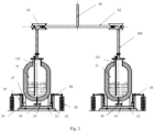
- the weighing unit includes four vertical branch pipes 100, four collection containers 11 and four weighing devices; the four vertical branch pipes communicate with corresponding horizontal pipes 92 respectively through a force balance compensator 10; the four vertical branch pipes are disposed right above the corresponding collection containers 11 respectively; the weighing devices are disposed below the 4 collection containers 11 correspondingly, and the weighing devices are configured to weight incremental liquids in the collection containers 11; and outlets of the collection containers 11 communicate with an inlet of the quick recovery container 14 through an isolation pipeline 12 and a second isolation valve 13, a liquid discharge valve 39 is disposed at the outlets of the collection containers 11, and by manually controlling opening and closing of the liquid discharge valve 39, the cryogenic mediums in the collection containers 11 are discharged to the weighing and filling recovery unit 15 or the recovery unit 16.
- the weighing and filling recovery unit 15 is configured to connect the tank wagon with the collection containers 11; and the recovery unit is configured to connect the quick recovery container 14 with the tank wagon.
- the weighing devices include weighing assemblies and two balance assemblies uniformly distributed on the weighing assemblies;
- the weight of the container 1 is large, if the load cells 32 are directly used to measure the weight, since the range of the load cells 32 is large, taking a 50m 3 container as an example, about four 100 kN or more are required, and the relative error is also relatively large. Therefore, four lever type force balancing devices are disposed around the platform.
- the container can be lifted. With the increase of valves, the weight of the container on the load cells 32 gradually decreases. In an ideal state, the weight of the container on the load cells 32 may be 0. In actual use, it is generally controlled within 100 kg.
- the load cells may be replaced with load cells with a small range, such as four 5 kN-level sensors. Through the structure, high-precision weighing of the cryogenic mediums entering the container can be realized.
- the container filling unit 2 includes a filling pipeline and a recovery pipeline connected to the filling pipeline in parallel, the filling pipeline is sequentially provided with a filling manual valve 25 and a filling filter 24 in a filling direction of the cryogenic medium, the recovery pipeline is sequentially provided with a recovery valve 21, a corrugated pipe compensator 22 and a filling interface 23 in a recovery direction of the cryogenic medium, the filling interface 23 is connected with the tank wagon through a hose, and the tank wagon is disposed near the container filling unit 2.
- a cryogenic medium outlet of the filling pipeline communicates with a bottom inlet of the container 1
- a bottom outlet of the container 1 communicates with inlets of the collection containers 11 through the supply pipeline
- outlets of the collection containers 11 communicate with the quick recovery container 14 through the isolation pipeline 12
- the isolation pipeline 12 adopts a force isolation hose
- the second isolation valve 13 is disposed on the force isolation hose.
- the weighing and filling recovery unit 15 has a same structure as the container filling unit 2, the weighing and filling recovery unit 15 is configured to fill the collection containers 11 with the cryogenic medium and recover the cryogenic medium therefrom, and the recovery unit 16 has a same structure with the recovery pipeline and is configured to recover the cryogenic mediums into the tank wagon.
- the force balance compensator 10 adopts an angle-type force balance compensator, the load cells are installed on a pull rod of the angle-type force balance compensator, and the collection containers 11 are fully enclosed vacuum sandwich containers; and the quick recovery container 14 is placed at a lower position and can be buried underground.
- the present invention can also add a set of exhaust system on each collection container 11, including a first exhaust pipeline and a second exhaust pipeline. Inlets of the first exhaust pipeline and the second exhaust pipeline both communicate with one of the collection containers 11, and outlets thereof are connected with an external gas purification system respectively; and the first exhaust pipeline includes an automatic exhaust valve 17, and the second exhaust pipeline includes a manual exhaust valve 18.
- the explosive and flammable gas at the outlets of the collection containers 11 can be exhausted by controlling the opening of the automatic exhaust valve 17.
- the manual exhaust valve 18 can be opened to exhaust the excess explosive and flammable gas in the collection containers 11.
- an exhaust system may further be installed on one of the collection containers 11, since the four collection containers 11 communicate with one another through the vertical main pipe 91, the flammable gas in all collection containers 11 may be exhausted.
- the calibration flow adjusting manual valve 9 is connected in parallel with a calibration pneumatic valve 99, when calibrating the reference flowmeter, the calibration pneumatic valve is controlled by the external control unit to quantitatively discharge a cryogenic medium in the supply pipeline to the weighing and filling recovery unit, so that the volume of the cryogenic medium decreasing in the same time period may be recorded many times.
- the present invention further provides a flowmeter calibration method for the cryogenic propellant rocket engine, including the following steps:
- step 1 in-situ calibration of a weighing unit
- Step 2 precooling of a cryogenic medium in-situ calibration system
- Step 3 in-situ calibration of a container
- a temporary network may be established between a running vehicle within a certain distance preset range and a peripheral device through the V2X communication module 102, road condition data is acquired through the front vehicle, the running data sharing packet is sent to the peripheral device, and the running vehicle within a certain distance threshold range of the peripheral device may receive the running data sharing packet within a certain time threshold range.
- the peripheral device includes various devices in the temporary network, e.g. a roadside fixed device with V2X communication function, or other vehicles with V2X communication function.
- the second isolation valve 13 is opened to discharge the weighed cryogenic mediums from the collection containers 11, which may be discharged to the quick recovery container 14, and if the liquid level in the quick recovery container 14 is too high, the recovery unit 16 may be used to discharge it.
- the system Since a plurality of previous precooling steps are performed by the system, the system is already at the basically same temperature as the cryogenic mediums, the evaporation capacity is very small, which is basically consistent with the water calibration. According to the situation that the weight of the mediums whose liquid level drops by 10 cm is 114 kg, the volume of this section of the collection container 11 is 0.1 m 3 . After weighing is completed each time, the second isolation valve 13 is used to discharge the weighed cryogenic mediums to the quick recovery container 14. If the liquid level in the quick recovery container 14 is too high, the recovery unit 16 may be used to discharge it.
- each equal height segment for example, the height segment with a unit of 10 cm
- the corresponding volume of each equal height segment for example, the height segment with a unit of 10 cm
- Step 4 calibration of a reference flowmeter
- the cryogenic mediums are discharged for a period of time according to expected time, and then the measured data is used to calculate and complete the calibration.
- the number of turns of the flowmeter that drops 20 cm from the liquid level of 5-15 s in the discharge process is 100.
- the containers calibrated at 20 cm are 0.1 m 3 and 0.11 m 3 respectively. Therefore, the discharge container for 5-15 s is 0.21 m 3 , and the volume of each turn of the flowmeter is 0.0021 m 3 .
- the gas generated by the volatilization of the cryogenic mediums in the system can be discharged before the calibration of the reference flowmeter.
- the cryogenic medium containing gas is safe and reliable with small emissions.
- the discharge calibration of the cryogenic mediums for a long time can be realized, and the calibration algorithm for the average flow can greatly improve the calibration accuracy.
Landscapes
- Physics & Mathematics (AREA)
- Fluid Mechanics (AREA)
- General Physics & Mathematics (AREA)
- Engineering & Computer Science (AREA)
- Mechanical Engineering (AREA)
- General Engineering & Computer Science (AREA)
- Filling Or Discharging Of Gas Storage Vessels (AREA)
Claims (9)
- Verfahren zur Kalibrierung eines Durchflussmessers für ein Raketentriebwerk mit kryogenem Treibstoff, wobei das Verfahren zur Kalibrierung des Durchflussmessers unter Verwendung eines Durchflussmesserkalibriersystems durchgeführt wird, wobei:das Durchflussmesserkalibriersystem eine Behälterfülleinheit (2), einen Behälter (1), eine Versorgungsleitung, eine Wägeeinheit, einen Schnellrückgewinnungsbehälter (14), eine Rückgewinnungseinheit (16) und eine Wäge- und Füllrückgewinnungseinheit (15), die hintereinander geschaltet sind, aufweist;die Behälterfülleinheit (2) dazu eingerichtet ist, einen Kesselwagen mit dem Behälter (1) zu verbinden;die Versorgungsleitung mindestens einen Temperatursensor und mindestens einen Drucksensor umfasst, die an beliebiger Stelle angeordnet sind, sowie ein erstes Absperrventil (4), einen Referenzdurchflussmesser (7), ein manuelles Kalibrierungsdurchflusseinstellventil (9), ein vertikales Hauptrohr (91) und N umfangsmäßig und gleichmäßig verteilte horizontale Rohre (92), die aufeinanderfolgend durch eine Rohrleitung verbunden sind, wobei 2 ≤ N ≤ 6; ein Einlass des ersten Absperrventils (4) mit einem Ablass des Behälters (1) verbunden ist und ein Ablass des vertikalen Hauptrohrs (91) jeweils mit Einlässen der N horizontalen Rohre (92) verbunden ist; das Durchflussmesserkalibriersystem ist so konfiguriert, dass es die Kalibrierung des Referenzdurchflussmessers (7) unter Verwendung eines kryogenen Mediums durchführt;die Wägeeinheit N vertikale Abzweigrohre (100), N Sammelbehälter (11) und N Wägevorrichtungen umfasst; die vertikalen Abzweigrohre jeweils mit den entsprechenden horizontalen Rohren (92) über einen Kraftausgleichskompensator (10) in Verbindung stehen; die vertikalen Abzweigrohre jeweils direkt über den entsprechenden Sammelbehältern (11) angeordnet sind; die Wägevorrichtungen jeweils unter den Sammelbehältern (11) angeordnet sind, und die Wägevorrichtungen so konfiguriert sind, dass sie inkrementelle Flüssigkeiten in den Sammelbehältern (11) wiegen; die N Sammelbehälter (11) den N horizontalen Rohren (92) entsprechen;Auslässe der Sammelbehälter (11) mit einem Einlass des Schnellrückgewinnungsbehälters (14) über eine Absperrleitung (12) und ein zweites Absperrventil (13) in Verbindung stehen;die Wäge- und Füllrückgewinnungseinheit (15) zur Verbindung des Kesselwagens mit den Sammelbehältern (11) ausgebildet ist;die Rückgewinnungseinheit so konfiguriert ist, dass sie den Schnellrückgewinnungsbehälter (14) mit dem Kesselwagen verbindet;die Wägevorrichtungen Wägebaugruppen und mindestens zwei Ausgleichsbaugruppen, die gleichmäßig auf den Wägebaugruppen verteilt sind, umfassen;jede Wägebaugruppe eine Basis (31), mindestens zwei Wägezellen (32), eine bewegliche Plattform (33) und einen Tragrahmen (34) umfasst, die aufeinanderfolgend von unten nach oben angeordnet sind; die mindestens zwei Wägezellen (32) gleichmäßig unter einer unteren Tischoberfläche der beweglichen Plattform (33) angeordnet sind, empfindliche Oberflächen der Wägezellen (32) in Spalt- oder Kontaktanordnung mit der unteren Tischoberfläche der beweglichen Plattform (33) sind, und der Tragrahmen (34) in einem mittleren Teil der beweglichen Plattform (33) installiert und konfiguriert ist, den entsprechenden Sammelbehälter (11) zu tragen;jede Wägebaugruppe eine auf der Basis (31) angeordnete Haltestange (35), einen an der Haltestange (35) angelenkten Hebel (36), eine Aufhängekette (37) und ein Gewicht (38) umfasst;ein inneres Ende des Hebels (36) über die Aufhängekette (37) mit der beweglichen Plattform (33) verbunden ist und das Gewicht (38) an einem äußeren Ende des Hebels aufgehängt ist;wobei das Verfahren zur Kalibrierung des Durchflussmessers die folgenden Schritte umfasst:Schritt 1: In-Situ-Kalibrierung einer WägeeinheitSchritt 1.1: Füllen von Sammelbehältern (11) mit kryogenen Medien durch eine Wäge- und Füllrückgewinnungseinheit (15) und Rückgewinnen der kryogenen Medien in den Sammelbehältern (11) in einen Schnellrückgewinnungsbehälter (14), wenn ein Füllflüssigkeitspegel in jedem Sammelbehälter (11) 70 % oder mehr erreicht und Temperaturen des kryogenen Mediums in den Sammelbehältern (11) < 5°C sind;Schritt 1.2: Aufzeichnen der Nullposition einer Wägezelle (32) und der Gesamtmasse mtotal der Gewichte (38) auf einer Wägevorrichtung;Schritt 1.3: Entladen von Gewichten mit einer voreingestellten Masse m0 an jedem Hebel (36) entsprechend einem nutzbaren Bereich der Wägezelle (32), Aufzeichnen eines Ausgangswertes V der Wägezelle (32) und der Masse m der verbleibenden Gewichte, auf dieser Basis erneutes Entladen der Gewichte mit der voreingestellten Masse m0, Aufzeichnen des Ausgangswerts V der Wägezelle (32) und der Masse m der verbleibenden Gewichte, und auf diese Weise M-maliges Entladen der Gewichte mit der Masse m0 und Aufzeichnen von insgesamt M Gruppen von Daten, wobei M ≥ 5, m0 = F/Mg, F ein maximaler Bereich der Wägezelle und g eine Erdbeschleunigung ist;Schritt 1.4: K-maliges Wiederholen von Schritt 1.3, wobei K ≥ 2, und Durchführen einer Anpassung der kleinsten Quadrate an die aufgezeichneten ((K+1)xM) Datengruppen, um eine entsprechende Beziehung zwischen V und (mtotal-m) zu erhalten, um die In-situ-Kalibrierung der Wägeeinheit abzuschließen;Schritt 2: Vorkühlen eines In-situ-Kalibriersystems mit kryogenem Medium;Vorkühlen der Sammelbehälter (11) und einer ersten Rohrleitung vor einem Behälter (1) und einem manuellen Versorgungsleitungsventil nacheinander und Kühlen einer zweiten Rohrleitung und vertikaler Abzweigrohre (100) hinter dem manuellen Versorgungsleitungsventil (9) durch die kryogenen Medien; Voraussetzen, dass eine Differenz zwischen einer Temperatur eines vorherigen Vorkühlbereichs und Temperaturen der kryogenen Medien unter einem Standardatmosphärendruck weniger als 5°C beträgt, bevor das Vorkühlen eines nächsten Vorkühlbereichs erfolgt;Schließen eines manuellen Kalibrierungsdurchflusseinstellventils (9), nachdem die Kühlung der zweiten Rohrleitung und der vertikalen Abzweigrohre (100) abgeschlossen ist, und Entleeren eines Rohrleitungssystems stromabwärts des manuellen Kalibrierungsdurchflusseinstellventils (9), um die Vorkühlung des In-situ-Kalibriersystems für das kryogene Medium zu realisieren;Schritt 3: In-situ-Kalibrierung eines Behälters;Schritt 3.1: Schließen eines zweiten Absperrventils (13), Öffnen eines ersten Absperrventils (4) und Füllen des Behälters (1) durch eine Behälterfülleinheit (2);Schritt 3.2: schrittweises Öffnen des manuellen Kalibrierungsdurchflusseinstellventils (9) in Abhängigkeit von der Abnahmehöhe des Flüssigkeitspegels, die für den Behälter (1) kalibriert werden muss, langsames Ablassen der kryogenen Medien im Behälter (1) in die Sammelbehälter (11), Wiegen jedes Sammelbehälters (11) unter Verwendung der Wägevorrichtung, Berechnen eines Volumens, das jeder Abnahmehöhe des Flüssigkeitspegels im Behälter (1) entspricht, und mindestens einmaliges Wiederholen, um die Kalibrierung des Behälters (1) abzuschließen;Öffnen des zweiten Absperrventils (13) nach Beendigung der Wägung, um die gewogenen kryogenen Medien aus den Sammelbehältern (11) abzulassen;Schritt 4: Kalibrierung eines Referenzdurchflussmessers;Schritt 4.1: Schließen des zweiten Absperrventils (13) oder Entfernen davon einer Absperrrohrleitung (12) und einer stromabwärts gelegenen Rohrleitung;Schließen des ersten Absperrventils (4) und des manuellen Kalibrierungsdurchflusseinstellventils (9) und Füllen des Behälters (1) durch die Behälterfülleinheit (2);Schritt 4.2: Öffnen des ersten Absperrventils (4) und eines pneumatischen Kalibrierungsventils (99), Ablassen des kryogenen Mediums aus der Wäge- und Füllrückgewinnungseinheit (15), nachdem es die Versorgungsleitung und die Sammelbehälter (11) durchlaufen hat, mehrmaliges Aufzeichnen des Volumens des kryogenen Mediums, das im Behälter (1) in der gleichen Zeitperiode abnimmt, Berechnen einer durchschnittlichen Durchflussrate der Versorgungsleitung in dieser Zeitperiode und Kalibrieren einer Durchflussrate des Referenzdurchflussmessers (7) durch die durchschnittliche Durchflussrate.
- Verfahren zur Kalibrierung eines Durchflussmessers für das Raketentriebwerk mit kryogenem Treibstoff nach Anspruch 1, dadurch gekennzeichnet, dass:
zwei Ausgleichsbaugruppen symmetrisch auf zwei Seiten der beweglichen Plattform (33) angeordnet ains. - Verfahren zur Kalibrierung des Durchflussmessers für das Raketentriebwerk mit kryogenem Treibstoff nach Anspruch 1 oder 2, dadurch gekennzeichnet, dass:
vier Sammelbehälter (11) angeordnet sind und die entsprechenden vier horizontalen Rohre (92) kreuzförmig verteilt sind. - Verfahren zur Kalibrierung eines Durchflussmessers für das Raketentriebwerk mit kryogenem Treibstoff nach Anspruch 3, dadurch gekennzeichnet, dass:das Durchflussmesserkalibriersystem ferner ein Ablasssystem für kryogenes Medium umfasst, das Ablasssystem für kryogenes Medium mindestens zwei Ablassleitungen umfasst, wobei die Einlässe der Ablassleitungen jeweils mit mindestens einem Sammelbehälter (11) in Verbindung stehen und ihre Auslässe jeweils mit einem externen Gasreinigungssystem verbunden sind; eine der Ablassleitungen mit einem automatischen Ablassventil (17) versehen ist, das automatische Ablassventil (17) durch eine externe Steuereinheit gesteuert wird, um Gas in den Sammelbehältern (11) abzulassen, und die anderen Ablassleitungen mit manuellen Ablassventilen (18) versehen sind;das manuelle Kalibrierungsdurchflusseinstellventil (9) parallel zu einem pneumatischen Kalibrierungsventil (99) geschaltet ist, und das pneumatische Kalibrierungsventil (99) von der externen Steuereinheit gesteuert wird, um ein kryogenes Medium in die Versorgungsleitung zur Wäge- und Füllungsrückgewinnungseinheit (15) abzugeben.
- Verfahren zur Kalibrierung eines Durchflussmessers für das Raketentriebwerk mit kryogenem Treibstoff nach Anspruch 4, dadurch gekennzeichnet, dass:die Behälterfülleinheit (2) eine Befüllungsleitung und eine mit der Befüllungsleitung verbundene Rückgewinnungsleitung umfasst, die Befüllungsleitung hintereinander mit einem manuellen Befüllungsventil (25) und einem Befüllungsfilter (24) in einer Befüllungsrichtung des kryogenen Mediums versehen ist, die Rückgewinnungsleitung hintereinander mit einem Rückgewinnungsventil (21), einem Wellrohrkompensator (22) und einer Befüllungsschnittstelle (23) in einer Rückgewinnungsrichtung des kryogenen Mediums versehen ist und die Befüllungsschnittstelle (23) mit dem Kesselwagen durch ein flexibles Rohr verbunden ist;die Wäge- und Füllrückgewinnungseinheit (15) die gleiche Struktur wie die Behälterfüllungseinheit (2) aufweist, die Wäge- und Füllrückgewinnungseinheit (15) so konfiguriert ist, dass sie die Sammelbehälter (11) mit dem kryogenen Medium füllt und das kryogene Medium daraus rückgewinnt, und die Rückgewinnungseinheit (16) die gleiche Struktur wie die Rückgewinnungsrohrleitung aufweist und so konfiguriert ist, dass sie das kryogene Medium in den Kesselwagen rückgewinnt.
- Verfahren zur Kalibrierung eines Durchflussmessers für das Raketentriebwerk mit kryogenem Treibstoff nach Anspruch 5, dadurch gekennzeichnet, dass:
der Kraftausgleichskompensator (10) ein Winkel-Kraftausgleichskompensator ist, und die Wägezellen an einer Zugstange des Winkel-Kraftausgleichskompensator installiert sind. - Verfahren zur Kalibrierung eines Durchflussmessers für das Raketentriebwerk mit kryogenem Treibstoff nach Anspruch 6, dadurch gekennzeichnet, dass:die Versorgungsleitung ferner mit einem Behälterboden-Wellkompensator (3), einem Behälter-Horizontalschnitt-Wellkompensator (5), einem Filter (6) und einem Mittel-Wellkompensator (8) in einer Transportrichtung des kryogenen Mediums versehen ist;die Sammelbehälter (11) vollständig geschlossene Vakuum-Sandwich-Behälter sind.
- Verfahren zur Kalibrierung des Durchflussmessers für das Raketentriebwerk mit kryogenem Treibstoff nach einem der vorhergehenden Ansprüche, dadurch gekennzeichnet, dass:
zwischen Schritt 4.1 und Schritt 4.2 das Verfahren zur Kalibrierung des Durchflussmessers außerdem Schritt 4.11 umfasst: Anschließen eines Ablasssystems für kryogene Medien an die Sammelbehälter (11), Öffnen eines automatischen Ablassventils (17) durch eine externe Steuereinheit und Ablassen von Gas, das durch Verflüchtigung der kryogenen Medien in dem System erzeugt wird; und Schließen des automatischen Ablassventils (17), wenn der Druck in dem System ≤0, 1 MPa ist. - Verfahren zur Kalibrierung des Durchflussmessers für das Raketentriebwerk mit kryogenem Treibstoff nach einem der vorhergehenden Ansprüche, dadurch gekennzeichnet, dass:
das Vorkühlen des In-situ-Kalibriersystems mit kryogenem Medium in Schritt 2 wie folgt ist:Schritt 2.1: Füllen der Sammelbehälter (11) mit den kryogenen Medien durch die Wäge- und Füllrückgewinnungseinheit (15) und währenddessen Füllen des Behälters (1) mit den kryogenen Medien durch die Behälterfülleinheit (2), wobei, wenn die Füllflüssigkeitspegel in den Sammelbehältern (11) alle 40 % oder mehr erreichen und der Füllflüssigkeitspegel des Behälters (1) 70 % oder mehr erreicht, das Vorkühlen der Sammelbehälter (11) und des Behälters (1) realisiert wird;Schritt 2.2: Öffnen des ersten Absperrventils (4), wenn die Temperaturen der kryogenen Medien in den Sammelbehältern (11) und dem Behälter (1) alle <5°C sind, Schließen des manuellen Kalibrierungsdurchflusseinstellventils (9) zur Einstellung des Kalibrierungsflusses, Kühlen der ersten Rohrleitung vor dem manuellen Versorgungsleitungsventil (9) durch die kryogenen Medien und zwischenzeitliches Öffnen des zweiten Absperrventils (13) zum Ablassen der kryogenen Medien in den Sammelbehältern (11);Schritt 2.3: Öffnen des manuellen Kalibrierungsdurchflusseinstellventils (9), wenn die Differenz zwischen der von einem Temperatursensor in der ersten Rohrleitung gemessenen Temperatur und den Temperaturen der kryogenen Medien unter dem atmosphärischen Standarddruck weniger als 5°C beträgt, und Kühlen der zweiten Rohrleitung und der vertikalen Abzweigrohre (100) hinter dem manuellen Versorgungsleitungsventil (9);Schritt 2.4: Schließen, wenn eine Differenz zwischen einer gemessenen Temperatur eines Temperatursensors in der zweiten Rohrleitung und den Temperaturen der kryogenen Medien unter dem atmosphärischen Standarddruck weniger als 5°C beträgt und der Druck der kryogenen Medien in der Versorgungsrohrleitung ≤0.05 Mpa, des manuellen Kalibrierungsflusseinstellventils (9) und Öffnen des zweiten Absperrventils (13), um die Vorkühlung des In-situ-Kalibriersystems für kryogene Medien nach dem Ablassen der kryogenen Medien aus den Sammelbehältern (11), der Absperrrohrleitung (12) und dem Schnellwiedergewinnungsbehälter (14) zu realisieren.
Applications Claiming Priority (2)
| Application Number | Priority Date | Filing Date | Title |
|---|---|---|---|
| CN202110892142.3A CN113588047B (zh) | 2021-08-04 | 2021-08-04 | 低温推进剂火箭发动机的流量计标定系统及方法 |
| PCT/CN2021/114962 WO2023010629A1 (zh) | 2021-08-04 | 2021-08-27 | 低温推进剂火箭发动机的流量计标定系统及方法 |
Publications (4)
| Publication Number | Publication Date |
|---|---|
| EP4155689A1 EP4155689A1 (de) | 2023-03-29 |
| EP4155689A4 EP4155689A4 (de) | 2024-01-10 |
| EP4155689C0 EP4155689C0 (de) | 2025-05-07 |
| EP4155689B1 true EP4155689B1 (de) | 2025-05-07 |
Family
ID=78255078
Family Applications (1)
| Application Number | Title | Priority Date | Filing Date |
|---|---|---|---|
| EP21945369.3A Active EP4155689B1 (de) | 2021-08-04 | 2021-08-27 | Durchflussmesserkalibrierungssystem und verfahren für kryogenen raketentreibstoffmotor |
Country Status (4)
| Country | Link |
|---|---|
| US (1) | US12181327B2 (de) |
| EP (1) | EP4155689B1 (de) |
| CN (1) | CN113588047B (de) |
| WO (1) | WO2023010629A1 (de) |
Families Citing this family (8)
| Publication number | Priority date | Publication date | Assignee | Title |
|---|---|---|---|---|
| CN114088168B (zh) * | 2021-11-09 | 2023-08-25 | 浙江浙能富兴燃料有限公司 | 一种液氢泵驱动的质量法液氢流量标准装置 |
| CN114087539B (zh) * | 2021-11-09 | 2023-08-25 | 浙江浙能技术研究院有限公司 | 一种基于动静态称重法的液氢流量标准装置 |
| CN114088169B (zh) * | 2021-11-09 | 2023-08-04 | 浙江浙能富兴燃料有限公司 | 一种气压驱动的双向质量法液氢流量标准装置 |
| CN114440133B (zh) * | 2021-12-17 | 2024-10-15 | 河南平高电气股份有限公司 | 用于sf6充气、放气回收装置的监测模块及流量计纠偏方法 |
| CN115876289B (zh) * | 2022-12-13 | 2025-06-10 | 浙江大学嘉兴研究院 | 一种单相低温流体流量计的标定装置 |
| CN117189419B (zh) * | 2023-09-13 | 2024-09-06 | 蓝箭航天空间科技股份有限公司 | 液体火箭发动机在线自动预冷系统及预冷方法 |
| US12618705B2 (en) | 2023-10-19 | 2026-05-05 | Korea Aerospace Research Institute | Method and apparatus for measuring level for calculating flow of propellant tank |
| CN118130078B (zh) * | 2024-05-10 | 2024-09-10 | 西安航天动力研究所 | 一种液体火箭发动机三工位低温阀门转级试验系统 |
Family Cites Families (23)
| Publication number | Priority date | Publication date | Assignee | Title |
|---|---|---|---|---|
| US3212318A (en) * | 1962-04-30 | 1965-10-19 | United Aircraft Corp | Calibration device |
| JP4113647B2 (ja) | 2000-01-31 | 2008-07-09 | トキコテクノ株式会社 | 流量計校正システム |
| US7055366B2 (en) * | 2004-05-21 | 2006-06-06 | Upchurch Scientific, Inc. | Flow sensor calibration methods and apparatus |
| CN202974416U (zh) | 2012-11-28 | 2013-06-05 | 丹东贝特自动化工程仪表有限公司 | 质量法液体流量标准装置的电子称标准器装置 |
| DE102014210545A1 (de) * | 2014-06-04 | 2015-12-17 | Robert Bosch Gmbh | Verfahren zum Kalibrieren von Durchflussmessern für fluide Medien |
| CN104634409B (zh) * | 2015-02-06 | 2019-03-26 | 中国运载火箭技术研究院 | 一种5m级贮箱容积标定装备及方法 |
| JP6350880B2 (ja) * | 2015-09-28 | 2018-07-04 | 株式会社タツノ | 校正装置 |
| CN106124006B (zh) * | 2016-06-16 | 2019-02-19 | 日照海达尔加气设备有限公司 | 一种高精度低温流量计检测系统及其方法 |
| CN107014468B (zh) * | 2017-03-02 | 2019-08-13 | 浙江省计量科学研究院 | 压缩气体驱动液体流量校准装置及其校准方法 |
| CN107131931B (zh) * | 2017-06-06 | 2020-02-21 | 西安航天动力试验技术研究所 | 姿控发动机高温推进剂稳态流量原位校准装置及校准方法 |
| CN109253780A (zh) * | 2017-07-12 | 2019-01-22 | 汽海马汽车有限公司 | 油耗仪校准装置 |
| CN107631786A (zh) * | 2017-09-04 | 2018-01-26 | 中国人民解放军63729部队 | 一种火箭加注量称重计量装置 |
| CN107941307B (zh) * | 2017-11-10 | 2021-02-26 | 西安航天动力试验技术研究所 | 一种常规大型液体发动机推进剂流量现场校准系统及方法 |
| RU2680986C1 (ru) * | 2018-03-06 | 2019-03-01 | Федеральное государственное бюджетное образовательное учреждение высшего образования "Уфимский государственный нефтяной технический университет" | Проливной динамический стенд |
| CN110857876B (zh) * | 2018-08-23 | 2024-07-02 | 中国石油天然气股份有限公司 | 气体流量原级标准系统 |
| MY208526A (en) * | 2019-04-10 | 2025-05-14 | Pvte Company Ltd | Calibration method for liquid flowmeter |
| CN110057614B (zh) * | 2019-05-14 | 2024-08-06 | 方圆标志认证集团有限公司 | 一种净水机净水量自动称量装置及其使用方法 |
| CN110231173B (zh) * | 2019-05-31 | 2021-02-26 | 西安航天动力试验技术研究所 | 一种微小流量供应测量装置 |
| CN111397699B (zh) | 2020-02-16 | 2021-07-16 | 西安航天动力试验技术研究所 | 一种称重测量装置、流量计校验系统及方法 |
| CN111256787A (zh) * | 2020-03-05 | 2020-06-09 | 中国人民解放军63729部队 | 一种发射场地面加注系统流量计在线高精度标定方法 |
| CN112903068B (zh) * | 2021-02-11 | 2025-02-07 | 烟台中隆仪表有限公司 | 一种非恒流低温静态质量法检定装置及其方法 |
| CN113252144B (zh) * | 2021-02-11 | 2025-02-07 | 烟台中隆仪表有限公司 | 一种超低温液体静态质量法检定装置及其方法 |
| CN113029303A (zh) * | 2021-03-01 | 2021-06-25 | 北京和瑞储能科技有限公司 | 一种密封式称重标定系统 |
-
2021
- 2021-08-04 CN CN202110892142.3A patent/CN113588047B/zh active Active
- 2021-08-27 EP EP21945369.3A patent/EP4155689B1/de active Active
- 2021-08-27 WO PCT/CN2021/114962 patent/WO2023010629A1/zh not_active Ceased
- 2021-08-27 US US18/002,405 patent/US12181327B2/en active Active
Also Published As
| Publication number | Publication date |
|---|---|
| US12181327B2 (en) | 2024-12-31 |
| EP4155689A4 (de) | 2024-01-10 |
| EP4155689C0 (de) | 2025-05-07 |
| US20230341254A1 (en) | 2023-10-26 |
| CN113588047B (zh) | 2022-05-10 |
| CN113588047A (zh) | 2021-11-02 |
| WO2023010629A1 (zh) | 2023-02-09 |
| EP4155689A1 (de) | 2023-03-29 |
Similar Documents
| Publication | Publication Date | Title |
|---|---|---|
| US12181327B2 (en) | Flowmeter calibration system and method for cryogenic propellant rocket engine | |
| KR101881781B1 (ko) | 교정장치 및 교정방법 | |
| CN107131931A (zh) | 姿控发动机高温推进剂稳态流量原位校准装置及校准方法 | |
| CN107941307B (zh) | 一种常规大型液体发动机推进剂流量现场校准系统及方法 | |
| CN114458477B (zh) | 基于低波动液位低温在线原位流量标定方法及系统 | |
| Büker et al. | Investigations on pressure dependence of Coriolis mass flow meters used at hydrogen refueling stations | |
| CN105403390A (zh) | 安全阀低温试验系统及安全阀低温试验方法 | |
| US7210300B2 (en) | Refrigerant charging system and method with cartridges | |
| De Huu et al. | Design of gravimetric primary standards for field-testing of hydrogen refuelling stations | |
| CN110031376B (zh) | 多级流变加载下的岩石气体渗透率测试方法 | |
| JP6288026B2 (ja) | 校正装置 | |
| CN119124914A (zh) | 一种液氢容器的液氢蒸发率检测方法及检测系统 | |
| CN111157180B (zh) | 一种飞艇地面泄漏量的测量系统及测试方法 | |
| CN109854957B (zh) | 一种封闭式的低填充率并联贮箱加注方法 | |
| CN109655370A (zh) | 车用lng气瓶静态蒸发率保压测试装置及测试方法 | |
| KR20200141988A (ko) | 가스 저장 탱크 충전 장치 | |
| CN102087159A (zh) | 双基准物的差压检漏方法 | |
| CN110939863A (zh) | 加氢测试装置 | |
| CN209656489U (zh) | 车用lng气瓶静态蒸发率保压测试装置 | |
| RU2379641C1 (ru) | Способ контроля герметичности заправленной рабочим телом гидравлической системы терморегулирования космического объекта, снабженной гидропневматическим компенсатором | |
| CN115014472B (zh) | 一种具有自校准功能的低温流体动态称重补偿方法 | |
| CN114252124B (zh) | 压缩气体存储容器容积计算方法、装置、计算机和介质 | |
| RU2402002C1 (ru) | Способ контроля герметичности заправленной рабочим телом гидравлической системы терморегулирования пилотируемого космического объекта, снабженной гидропневматическим компенсатором температурного изменения объема рабочего тела | |
| JP2002013973A (ja) | 粉体重量計測装置 | |
| RU2381966C2 (ru) | Способ определения объема нерастворенного газа в жидкостной полости емкости, имеющей подвижный разделитель сред "газ-жидкость" |
Legal Events
| Date | Code | Title | Description |
|---|---|---|---|
| STAA | Information on the status of an ep patent application or granted ep patent |
Free format text: STATUS: UNKNOWN |
|
| STAA | Information on the status of an ep patent application or granted ep patent |
Free format text: STATUS: THE INTERNATIONAL PUBLICATION HAS BEEN MADE |
|
| PUAI | Public reference made under article 153(3) epc to a published international application that has entered the european phase |
Free format text: ORIGINAL CODE: 0009012 |
|
| STAA | Information on the status of an ep patent application or granted ep patent |
Free format text: STATUS: REQUEST FOR EXAMINATION WAS MADE |
|
| 17P | Request for examination filed |
Effective date: 20221222 |
|
| AK | Designated contracting states |
Kind code of ref document: A1 Designated state(s): AL AT BE BG CH CY CZ DE DK EE ES FI FR GB GR HR HU IE IS IT LI LT LU LV MC MK MT NL NO PL PT RO RS SE SI SK SM TR |
|
| REG | Reference to a national code |
Ref country code: DE Free format text: PREVIOUS MAIN CLASS: G01F0025000000 Ipc: G01F0025170000 Ref country code: DE Ref legal event code: R079 Ref document number: 602021030641 Country of ref document: DE Free format text: PREVIOUS MAIN CLASS: G01F0025000000 Ipc: G01F0025170000 |
|
| A4 | Supplementary search report drawn up and despatched |
Effective date: 20231211 |
|
| RIC1 | Information provided on ipc code assigned before grant |
Ipc: G01F 25/10 20220101ALI20231206BHEP Ipc: G01F 25/17 20220101AFI20231206BHEP |
|
| DAV | Request for validation of the european patent (deleted) | ||
| DAX | Request for extension of the european patent (deleted) | ||
| GRAP | Despatch of communication of intention to grant a patent |
Free format text: ORIGINAL CODE: EPIDOSNIGR1 |
|
| STAA | Information on the status of an ep patent application or granted ep patent |
Free format text: STATUS: GRANT OF PATENT IS INTENDED |
|
| RIC1 | Information provided on ipc code assigned before grant |
Ipc: G01F 25/10 20220101ALI20241206BHEP Ipc: G01F 25/17 20220101AFI20241206BHEP |
|
| INTG | Intention to grant announced |
Effective date: 20250102 |
|
| GRAS | Grant fee paid |
Free format text: ORIGINAL CODE: EPIDOSNIGR3 |
|
| GRAA | (expected) grant |
Free format text: ORIGINAL CODE: 0009210 |
|
| STAA | Information on the status of an ep patent application or granted ep patent |
Free format text: STATUS: THE PATENT HAS BEEN GRANTED |
|
| AK | Designated contracting states |
Kind code of ref document: B1 Designated state(s): AL AT BE BG CH CY CZ DE DK EE ES FI FR GB GR HR HU IE IS IT LI LT LU LV MC MK MT NL NO PL PT RO RS SE SI SK SM TR |
|
| REG | Reference to a national code |
Ref country code: GB Ref legal event code: FG4D |
|
| REG | Reference to a national code |
Ref country code: CH Ref legal event code: EP |
|
| REG | Reference to a national code |
Ref country code: DE Ref legal event code: R096 Ref document number: 602021030641 Country of ref document: DE |
|
| REG | Reference to a national code |
Ref country code: IE Ref legal event code: FG4D |
|
| U01 | Request for unitary effect filed |
Effective date: 20250604 |
|
| U07 | Unitary effect registered |
Designated state(s): AT BE BG DE DK EE FI FR IT LT LU LV MT NL PT RO SE SI Effective date: 20250611 |
|
| U20 | Renewal fee for the european patent with unitary effect paid |
Year of fee payment: 5 Effective date: 20250826 |
|
| PG25 | Lapsed in a contracting state [announced via postgrant information from national office to epo] |
Ref country code: ES Free format text: LAPSE BECAUSE OF FAILURE TO SUBMIT A TRANSLATION OF THE DESCRIPTION OR TO PAY THE FEE WITHIN THE PRESCRIBED TIME-LIMIT Effective date: 20250507 |
|
| PG25 | Lapsed in a contracting state [announced via postgrant information from national office to epo] |
Ref country code: NO Free format text: LAPSE BECAUSE OF FAILURE TO SUBMIT A TRANSLATION OF THE DESCRIPTION OR TO PAY THE FEE WITHIN THE PRESCRIBED TIME-LIMIT Effective date: 20250807 Ref country code: GR Free format text: LAPSE BECAUSE OF FAILURE TO SUBMIT A TRANSLATION OF THE DESCRIPTION OR TO PAY THE FEE WITHIN THE PRESCRIBED TIME-LIMIT Effective date: 20250808 |
|
| PG25 | Lapsed in a contracting state [announced via postgrant information from national office to epo] |
Ref country code: PL Free format text: LAPSE BECAUSE OF FAILURE TO SUBMIT A TRANSLATION OF THE DESCRIPTION OR TO PAY THE FEE WITHIN THE PRESCRIBED TIME-LIMIT Effective date: 20250507 |
|
| PG25 | Lapsed in a contracting state [announced via postgrant information from national office to epo] |
Ref country code: HR Free format text: LAPSE BECAUSE OF FAILURE TO SUBMIT A TRANSLATION OF THE DESCRIPTION OR TO PAY THE FEE WITHIN THE PRESCRIBED TIME-LIMIT Effective date: 20250507 |
|
| PG25 | Lapsed in a contracting state [announced via postgrant information from national office to epo] |
Ref country code: RS Free format text: LAPSE BECAUSE OF FAILURE TO SUBMIT A TRANSLATION OF THE DESCRIPTION OR TO PAY THE FEE WITHIN THE PRESCRIBED TIME-LIMIT Effective date: 20250807 |
|
| PG25 | Lapsed in a contracting state [announced via postgrant information from national office to epo] |
Ref country code: IS Free format text: LAPSE BECAUSE OF FAILURE TO SUBMIT A TRANSLATION OF THE DESCRIPTION OR TO PAY THE FEE WITHIN THE PRESCRIBED TIME-LIMIT Effective date: 20250907 |
|
| PG25 | Lapsed in a contracting state [announced via postgrant information from national office to epo] |
Ref country code: SM Free format text: LAPSE BECAUSE OF FAILURE TO SUBMIT A TRANSLATION OF THE DESCRIPTION OR TO PAY THE FEE WITHIN THE PRESCRIBED TIME-LIMIT Effective date: 20250507 |
|
| PG25 | Lapsed in a contracting state [announced via postgrant information from national office to epo] |
Ref country code: CZ Free format text: LAPSE BECAUSE OF FAILURE TO SUBMIT A TRANSLATION OF THE DESCRIPTION OR TO PAY THE FEE WITHIN THE PRESCRIBED TIME-LIMIT Effective date: 20250507 |
|
| PG25 | Lapsed in a contracting state [announced via postgrant information from national office to epo] |
Ref country code: SK Free format text: LAPSE BECAUSE OF FAILURE TO SUBMIT A TRANSLATION OF THE DESCRIPTION OR TO PAY THE FEE WITHIN THE PRESCRIBED TIME-LIMIT Effective date: 20250507 |
|
| PLBE | No opposition filed within time limit |
Free format text: ORIGINAL CODE: 0009261 |
|
| STAA | Information on the status of an ep patent application or granted ep patent |
Free format text: STATUS: NO OPPOSITION FILED WITHIN TIME LIMIT |
|
| REG | Reference to a national code |
Ref country code: CH Ref legal event code: L10 Free format text: ST27 STATUS EVENT CODE: U-0-0-L10-L00 (AS PROVIDED BY THE NATIONAL OFFICE) Effective date: 20260318 |
|
| REG | Reference to a national code |
Ref country code: CH Ref legal event code: H13 Free format text: ST27 STATUS EVENT CODE: U-0-0-H10-H13 (AS PROVIDED BY THE NATIONAL OFFICE) Effective date: 20260324 |
|
| PG25 | Lapsed in a contracting state [announced via postgrant information from national office to epo] |
Ref country code: MC Free format text: LAPSE BECAUSE OF FAILURE TO SUBMIT A TRANSLATION OF THE DESCRIPTION OR TO PAY THE FEE WITHIN THE PRESCRIBED TIME-LIMIT Effective date: 20250507 |
|
| 26N | No opposition filed |
Effective date: 20260210 |
|
| PG25 | Lapsed in a contracting state [announced via postgrant information from national office to epo] |
Ref country code: CH Free format text: LAPSE BECAUSE OF NON-PAYMENT OF DUE FEES Effective date: 20250831 |
|
| GBPC | Gb: european patent ceased through non-payment of renewal fee |
Effective date: 20250827 |