EP4155656A1 - Heat exchanger and heat exchanger manufacturing method - Google Patents
Heat exchanger and heat exchanger manufacturing method Download PDFInfo
- Publication number
- EP4155656A1 EP4155656A1 EP21809841.6A EP21809841A EP4155656A1 EP 4155656 A1 EP4155656 A1 EP 4155656A1 EP 21809841 A EP21809841 A EP 21809841A EP 4155656 A1 EP4155656 A1 EP 4155656A1
- Authority
- EP
- European Patent Office
- Prior art keywords
- heat transfer
- corrugated sheet
- base
- heat exchanger
- transfer tubes
- Prior art date
- Legal status (The legal status is an assumption and is not a legal conclusion. Google has not performed a legal analysis and makes no representation as to the accuracy of the status listed.)
- Granted
Links
Images










Classifications
-
- F—MECHANICAL ENGINEERING; LIGHTING; HEATING; WEAPONS; BLASTING
- F28—HEAT EXCHANGE IN GENERAL
- F28F—DETAILS OF HEAT-EXCHANGE AND HEAT-TRANSFER APPARATUS, OF GENERAL APPLICATION
- F28F9/00—Casings; Header boxes; Auxiliary supports for elements; Auxiliary members within casings
- F28F9/02—Header boxes; End plates
- F28F9/0219—Arrangements for sealing end plates into casing or header box; Header box sub-elements
- F28F9/0224—Header boxes formed by sealing end plates into covers
-
- F—MECHANICAL ENGINEERING; LIGHTING; HEATING; WEAPONS; BLASTING
- F28—HEAT EXCHANGE IN GENERAL
- F28D—HEAT-EXCHANGE APPARATUS, NOT PROVIDED FOR IN ANOTHER SUBCLASS, IN WHICH THE HEAT-EXCHANGE MEDIA DO NOT COME INTO DIRECT CONTACT
- F28D7/00—Heat-exchange apparatus having stationary tubular conduit assemblies for both heat-exchange media, the media being in contact with different sides of a conduit wall
- F28D7/16—Heat-exchange apparatus having stationary tubular conduit assemblies for both heat-exchange media, the media being in contact with different sides of a conduit wall the conduits being arranged in parallel spaced relation
-
- F—MECHANICAL ENGINEERING; LIGHTING; HEATING; WEAPONS; BLASTING
- F28—HEAT EXCHANGE IN GENERAL
- F28D—HEAT-EXCHANGE APPARATUS, NOT PROVIDED FOR IN ANOTHER SUBCLASS, IN WHICH THE HEAT-EXCHANGE MEDIA DO NOT COME INTO DIRECT CONTACT
- F28D1/00—Heat-exchange apparatus having stationary conduit assemblies for one heat-exchange medium only, the media being in contact with different sides of the conduit wall, in which the other heat-exchange medium is a large body of fluid, e.g. domestic or motor car radiators
- F28D1/02—Heat-exchange apparatus having stationary conduit assemblies for one heat-exchange medium only, the media being in contact with different sides of the conduit wall, in which the other heat-exchange medium is a large body of fluid, e.g. domestic or motor car radiators with heat-exchange conduits immersed in the body of fluid
- F28D1/04—Heat-exchange apparatus having stationary conduit assemblies for one heat-exchange medium only, the media being in contact with different sides of the conduit wall, in which the other heat-exchange medium is a large body of fluid, e.g. domestic or motor car radiators with heat-exchange conduits immersed in the body of fluid with tubular conduits
- F28D1/053—Heat-exchange apparatus having stationary conduit assemblies for one heat-exchange medium only, the media being in contact with different sides of the conduit wall, in which the other heat-exchange medium is a large body of fluid, e.g. domestic or motor car radiators with heat-exchange conduits immersed in the body of fluid with tubular conduits the conduits being straight
- F28D1/0535—Heat-exchange apparatus having stationary conduit assemblies for one heat-exchange medium only, the media being in contact with different sides of the conduit wall, in which the other heat-exchange medium is a large body of fluid, e.g. domestic or motor car radiators with heat-exchange conduits immersed in the body of fluid with tubular conduits the conduits being straight the conduits having a non-circular cross-section
- F28D1/05366—Assemblies of conduits connected to common headers, e.g. core type radiators
-
- F—MECHANICAL ENGINEERING; LIGHTING; HEATING; WEAPONS; BLASTING
- F28—HEAT EXCHANGE IN GENERAL
- F28F—DETAILS OF HEAT-EXCHANGE AND HEAT-TRANSFER APPARATUS, OF GENERAL APPLICATION
- F28F1/00—Tubular elements; Assemblies of tubular elements
- F28F1/10—Tubular elements and assemblies thereof with means for increasing heat-transfer area, e.g. with fins, with projections, with recesses
- F28F1/12—Tubular elements and assemblies thereof with means for increasing heat-transfer area, e.g. with fins, with projections, with recesses the means being only outside the tubular element
-
- F—MECHANICAL ENGINEERING; LIGHTING; HEATING; WEAPONS; BLASTING
- F28—HEAT EXCHANGE IN GENERAL
- F28F—DETAILS OF HEAT-EXCHANGE AND HEAT-TRANSFER APPARATUS, OF GENERAL APPLICATION
- F28F9/00—Casings; Header boxes; Auxiliary supports for elements; Auxiliary members within casings
- F28F9/02—Header boxes; End plates
- F28F9/0202—Header boxes having their inner space divided by partitions
- F28F9/0204—Header boxes having their inner space divided by partitions for elongated header box, e.g. with transversal and longitudinal partitions
-
- F—MECHANICAL ENGINEERING; LIGHTING; HEATING; WEAPONS; BLASTING
- F28—HEAT EXCHANGE IN GENERAL
- F28F—DETAILS OF HEAT-EXCHANGE AND HEAT-TRANSFER APPARATUS, OF GENERAL APPLICATION
- F28F9/00—Casings; Header boxes; Auxiliary supports for elements; Auxiliary members within casings
- F28F9/02—Header boxes; End plates
- F28F9/026—Header boxes; End plates with static flow control means, e.g. with means for uniformly distributing heat exchange media into conduits
- F28F9/0278—Header boxes; End plates with static flow control means, e.g. with means for uniformly distributing heat exchange media into conduits in the form of stacked distribution plates or perforated plates arranged over end plates
-
- F—MECHANICAL ENGINEERING; LIGHTING; HEATING; WEAPONS; BLASTING
- F28—HEAT EXCHANGE IN GENERAL
- F28D—HEAT-EXCHANGE APPARATUS, NOT PROVIDED FOR IN ANOTHER SUBCLASS, IN WHICH THE HEAT-EXCHANGE MEDIA DO NOT COME INTO DIRECT CONTACT
- F28D21/00—Heat-exchange apparatus not covered by any of the groups F28D1/00 - F28D20/00
- F28D2021/0019—Other heat exchangers for particular applications; Heat exchange systems not otherwise provided for
- F28D2021/0068—Other heat exchangers for particular applications; Heat exchange systems not otherwise provided for for refrigerant cycles
-
- F—MECHANICAL ENGINEERING; LIGHTING; HEATING; WEAPONS; BLASTING
- F28—HEAT EXCHANGE IN GENERAL
- F28F—DETAILS OF HEAT-EXCHANGE AND HEAT-TRANSFER APPARATUS, OF GENERAL APPLICATION
- F28F2275/00—Fastening; Joining
- F28F2275/12—Fastening; Joining by methods involving deformation of the elements
- F28F2275/122—Fastening; Joining by methods involving deformation of the elements by crimping, caulking or clinching
Definitions
- the present disclosure relates a heat exchanger having a bridging header and a method of manufacturing a heat exchanger.
- a heat exchanger having pairs of mutually facing heat transfer tubes.
- the heat transfer tubes in a first row and the heat transfer tubes in a second row extend parallel to one another.
- a bridging header into which end portions of the heat transfer tubes are inserted has flow passages.
- refrigerant flows only between a pair of the heat transfer tubes. That is, in the bridging header, the refrigerant that has flowed into the bridging header from a heat transfer tube arranged in the first row does not merge with the flow of the refrigerant that has flowed into the bridging header from another heat transfer tube arranged in the first row.
- Patent Literature 1 discloses a heat exchanger having a base into which heat transfer tubes are inserted and a bridging header constituted by a corrugated sheet that is provided on the base and that has a wavy shape in which semicircular column portions are continuously formed. Each of the semicircular column portions of the corrugated sheet covers points at which the paired heat transfer tubes are inserted and forms a flow passage between the semicircular column portion and the base.
- Patent Literature 1 Japanese Patent No. 5786877
- the corrugated sheet of the heat exchanger of Patent Literature 1 is required to be thickened so as not to be deformed by the pressure of the refrigerant flowing through the bridging header. In most cases, a thickened corrugated sheet is likely to interfere with the inserted heat transfer tube and is likely to cover, in a hindering way, a point at which the heat transfer tube is inserted. In the heat exchanger of the Patent Literature 1, because being thickened, the corrugated sheet reduces a region, in the base, into which the heat transfer tubes can be inserted. Thus, regarding the heat exchanger of Patent Literature 1, for example, the number of the heat transfer tubes that are inserted into the bridging header and a space between the heat transfer tubes are limited, and design flexibility is thus decreased.
- the present disclosure has been made to solve such an above-described problem and provides: a heat exchanger enabling adjustment of, for example, the number of the heat transfer tubes that are inserted into a bridging header and a space between the heat transfer tubes and thus enabling increase in design flexibility; and a method of manufacturing the heat exchanger.
- a heat exchanger of one embodiment of the present disclosure has: a heat transfer tube group made up of plural heat transfer tubes each of which has, inside the heat transfer tube, a flow passage through which refrigerant flows, the plural heat transfer tubes that are arranged in a lateral direction being arranged in a longitudinal direction so as to form plural rows; a fin provided on the heat transfer tubes and facilitating heat exchange between refrigerant flowing inside the heat transfer tubes and air; and a bridging header into which end portions of the heat transfer tubes are inserted and that causes refrigerant to flow between the heat transfer tubes arranged in a lateral direction of the heat transfer tube group.
- the bridging header has a base having a flat plate shape and having insertion holes into which respective ones of end portions of the plurality of heat transfer tubes are inserted.
- the bridging header also has a corrugated sheet being a plate having a shape of a wave in which crest portions and valley portions are continuously formed, each of the crest portions being provided so as to cover a pair of the insertion holes arranged in a lateral direction, the valley portions being in contact with the base on both sides of each of the insertion holes in a longitudinal direction of the base, the corrugated sheet forming, between the corrugated sheet and the base, a header flow passage, through which refrigerant flows, for every the heat transfer tubes arranged in a lateral direction of the heat transfer tube group.
- the bridging header also has a covering plate covering the corrugated sheet and pressing the corrugated sheet toward the base.
- a method of manufacturing a heat exchanger of another embodiment of the present disclosure includes: assembling: a heat transfer tube group made up of plural heat transfer tubes each of which has, inside the heat transfer tube, a flow passage through which refrigerant flows, the plural heat transfer tubes that are arranged in a lateral direction being arranged in a longitudinal direction so as to form plural rows; a fin provided on the heat transfer tubes and facilitating heat exchange between refrigerant flowing inside the heat transfer tubes and air; and a bridging header into which end portions of the heat transfer tubes are inserted and that causes refrigerant to flow between the heat transfer tubes arranged in a lateral direction of the heat transfer tube group.
- the method also includes performing brazing of the heat transfer tube group, the fin, and the bridging header.
- the assembling includes: fitting the corrugated sheet of the bridging header into the base, of the bridging header, having insertion holes into which respective ones of end portions of the plurality of heat transfer tubes are inserted, the fitting being performed so that, in the corrugated sheet being a plate having a shape of a wave in which crest portions and valley portions are continuously formed, each of the crest portions covers a pair of the insertion holes arranged in a lateral direction, and the valley portions are in contact with the base on both sides of each of the insertion holes in a longitudinal direction of the base; and carrying out attachment of a covering plate so that the covering plate covers the corrugated sheet.
- the bridging header has the covering plate that presses the corrugated sheet toward the base.
- the corrugated sheet is suppressed from being deformed by the pressure of the refrigerant flowing through the bridging header. That is, for suppressing the corrugated sheet from being deformed by the pressure of the refrigerant flowing through the bridging header, the corrugated sheet is not required to be thickened. Consequently, regarding the heat exchanger, for example, the number of the heat transfer tubes that are inserted into the bridging header and a space between the heat transfer tubes can be adjusted, and design flexibility can thus be increased.
- FIG. 1 is a circuit diagram of the air-conditioning apparatus 1 according to Embodiment 1. As Fig. 1 illustrates, the air-conditioning apparatus 1 has an outdoor unit 2, an indoor unit 3, and a refrigerant pipe 4. Note that, although Fig. 1 illustrates the single indoor unit 3, the number of the indoor units 3 may be two or more.
- the outdoor unit 2 includes a compressor 5, a flow-switching device 6, the heat exchanger 7, an outdoor fan 8, and an expansion unit 9.
- the indoor unit 3 includes an indoor heat exchanger 11 and an indoor fan 12.
- the refrigerant pipe 4 constitutes a refrigerant circuit by connecting the compressor 5, the flow-switching device 6, the heat exchanger 7, the expansion unit 9, and the indoor heat exchanger 11 to one another and by allowing refrigerant to flow inside the refrigerant pipe 4.
- the compressor 5 sucks low-temperature and low-pressure refrigerant, compresses the sucked refrigerant to bring the refrigerant into a high-temperature and high-pressure state, and discharges the refrigerant.
- the flow-switching device 6 switches flowing directions of refrigerant in the refrigerant circuit and is, for example, a four-way valve.
- the heat exchanger 7 exchanges heat between refrigerant and outdoor air.
- the heat exchanger 7 operates as a condenser during a cooling operation and operates as an evaporator during a heating operation.
- the outdoor fan 8 is a device for sending outdoor air to the heat exchanger 7.
- the expansion unit 9 is a pressure-reducing valve or an expansion valve for reducing the pressure of refrigerant to expand the refrigerant.
- the indoor heat exchanger 11 exchanges heat between indoor air and refrigerant.
- the indoor heat exchanger 11 operates as an evaporator during the cooling operation and operates as a condenser during the heating operation.
- the indoor fan 12 is a device for sending indoor air to the indoor heat exchanger 11.
- the cooling operation will be described.
- the refrigerant sucked into the compressor 5 is compressed by the compressor 5, and the refrigerant that has turned into a high-temperature and high-pressure gas state is discharged from the compressor 5.
- the high-temperature and high-pressure gas state refrigerant that has been discharged from the compressor 5 passes through the flow-switching device 6 and flows into the heat exchanger 7 operating as a condenser.
- the refrigerant that has flowed into the heat exchanger 7 exchanges heat with the outdoor air sent by the outdoor fan 8 and is thus condensed to be liquefied.
- the refrigerant in a liquid state flows into the expansion unit 9 and is reduced in pressure and expanded to turn into a low-temperature and low-pressure two-phase gas-liquid state.
- the refrigerant in a gas-liquid two-phase state flows into the indoor heat exchanger 11 operating as an evaporator.
- the refrigerant that has flowed into the indoor heat exchanger 11 exchanges heat with the indoor air sent by the indoor fan 12 and is thus evaporated to be gasified.
- the indoor air is cooled and air cooling is performed in a room.
- the evaporated refrigerant in a low-temperature and low-pressure gas state passes through the flow-switching device 6 and is sucked into the compressor 5.
- the heating operation will be described.
- the refrigerant sucked into the compressor 5 is compressed by the compressor 5, and the refrigerant that has turned into a high-temperature and high-pressure gas state is discharged from the compressor 5.
- the high-temperature and high-pressure gas state refrigerant that has been discharged from the compressor 5 passes through the flow-switching device 6 and flows into the indoor heat exchanger 11 operating as a condenser.
- the refrigerant that has flowed into the indoor heat exchanger 11 exchanges heat with the indoor air sent by the indoor fan 12 and is thus condensed to be liquefied. At this time, the indoor air is heated and air heating is performed in the room.
- the refrigerant in a liquid state flows into the expansion unit 9 and is reduced in pressure and expanded to turn into a low-temperature and low-pressure two-phase gas-liquid state.
- the refrigerant in a gas-liquid two-phase state flows into the heat exchanger 7 operating as an evaporator.
- the refrigerant that has flowed into the heat exchanger 7 exchanges heat with the outdoor air sent by the outdoor fan 8 and is thus evaporated to be gasified. Subsequently, the evaporated refrigerant in a low-temperature and low-pressure gas state passes through the flow-switching device 6 and is sucked into the compressor 5.
- Fig. 2 is a perspective view of the heat exchanger 7 according to Embodiment 1.
- the heat exchanger 7 has a heat transfer tube group 20, a fin 22, a first lower header 23, a bridging header 24, and a second lower header 25. Note that a configuration similar to the configuration of the heat exchanger 7 may be applied to the indoor heat exchanger 11.
- the heat transfer tube group 20 is constituted by plural heat transfer tubes 21.
- the heat transfer tubes 21 arranged in the lateral direction are arranged in the longitudinal direction so as to form plural rows.
- the heat transfer tubes 21 are, for example, flat tubes and have plural flow passages (not illustrated) inside which refrigerant flows.
- each of the heat transfer tubes 21 extends in the vertical direction.
- the heat transfer tube 21 may alternatively extend in a direction other than the vertical direction. In this case, other parts of the heat exchanger 7 are also assembled based on the direction where the heat transfer tube 21 extends.
- the heat transfer tubes 21 form two rows that are a first row and a second row extending parallel to one another. Note that the heat transfer tubes 21 may extend in three or more rows.
- the fin 22, which is, for example, a corrugated fin, is provided on the heat transfer tubes 21 and facilitates heat exchange between the refrigerant flowing inside the heat transfer tubes 21 and air.
- the first lower header 23 is a header into which an end portion on one side of each of the heat transfer tubes 21 arranged in the first row is inserted.
- the refrigerant pipe 4 is connected to the first lower header 23.
- the first lower header 23 distributes the refrigerant that has flowed into the first lower header 23 from the refrigerant pipe 4 to the heat transfer tubes 21 arranged in the first row.
- the first lower header 23 also causes the refrigerant that has merged with the refrigerant flow in the first lower header 23 from the heat transfer tubes 21 arranged in the first row to flow out into the refrigerant pipe 4.
- the bridging header 24 is a header that faces the first lower header 23 and the second lower header 25 and into which an end portion on the other side of each of the heat transfer tubes 21 arranged in the first row and in the second row is inserted.
- the bridging header 24 distributes the refrigerant that has merged with the refrigerant flow in the bridging header 24 from a heat transfer tube 21 arranged in the first row to a heat transfer tube 21 arranged in the second row.
- the bridging header 24 also distributes the refrigerant that has merged with the refrigerant flow in the bridging header 24 from the heat transfer tube 21 arranged in the second row to the heat transfer tube 21 arranged in the first row and facing, in the lateral direction, the heat transfer tube 21 arranged in the second row.
- Fig. 3 is a side view of the bridging header 24 according to Embodiment 1.
- Fig. 3 illustrates the bridging header 24, when the bridging header 24 is viewed in the longitudinal direction.
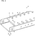
- Fig. 4 is a perspective view of the bridging header 24 according to Embodiment 1.
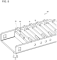
- Fig. 5 is a perspective view of the bridging header 24 according to Embodiment 1. Note that, in Fig. 5 , a covering plate 34 is transparent for an illustration purpose.
- the bridging header 24 has a base 31, a corrugated sheet 32, the covering plate 34, and an end plate 33.
- Fig. 6 is a perspective view of the base 31 according to Embodiment 1.
- Fig. 7 is a perspective view of the base 31 according to Embodiment 1.
- the base 31 is a flat plate-shaped part into which the heat transfer tubes 21 are inserted.
- the base 31 is constituted by a bottom base 41 and a side base 42.
- the bottom base 41 is a plate-shaped part constituting the bottom of the base 31 and having plural insertion holes 51 and a plate hole 52.
- the insertion holes 51 are openings into which the end portions of the heat transfer tubes 21 are inserted.
- two holes are arranged in the lateral direction and are paired.
- the insertion holes 51 are further arranged, in two rows, in the longitudinal direction.
- the plate hole 52 is an opening into which the end plate 33 is fitted.
- the plate hole 52 is opened substantially throughout the width of the bottom base 41 in the lateral direction.
- the side base 42 is a plate-shaped part constituting a side of the base 31 and extending, from an edge portion of the bottom base 41, along an edge of the corrugated sheet 32 extending in the longitudinal direction.
- Two side bases 42 are provided in the longitudinal direction of the heat exchanger 7.
- Each of the side bases 42 has plural claw portions 61 and plural catching protrusions 62.
- Fig. 8 illustrates the configuration of the bridging header 24 according to Embodiment 1.
- Fig. 9 is a perspective view of the bridging header 24 according to Embodiment 1.
- Fig. 8 illustrates the section of the bridging header 24 taken in the A-A direction illustrated in Fig. 3 . That is, Fig. 8 illustrates the section of the bridging header 24 taken in the longitudinal direction.
- the covering plate 34 is transparent, and the corrugated sheet 32 is semitransparent.
- each of the claw portions 61 is a claw-shaped part protruding from an upper end portion of the side base 42 toward the covering plate 34.
- each of the catching protrusions 62 is a substantially hollow cylindrical part protruding from an inner wall surface of the side base 42.
- the catching protrusions 62 catches upper end portions, in the lateral direction, crest portions 71 of the corrugated sheet 32, which will be described later.
- the side base 42 may have no catching protrusion 62.
- the corrugated sheet 32 is a sheet having a shape of a wave in which the crest portions 71 and valley portions 72 are continuously formed.
- Each of the crest portions 71 forms an arch shape in an upper region of the corrugated sheet 32.
- Each of the valley portions 72 forms an arch shape in a lower region of the corrugated sheet 32.
- Each of the crest portions 71 covers a pair of the insertion holes 51 arranged in the lateral direction of the heat transfer tube group 20. That is, a header flow passage 74 through which refrigerant flows is formed, between each of the crest portions 71 and the base 31, for every the heat transfer tubes 21 arranged in the lateral direction of the heat transfer tube group 20.
- the uppermost portion of the crest portion 71 is in contact with the covering plate 34.
- the lowermost portions of the valley portions 72 are in contact with the base 31 on both sides of each of the insertion holes 51.
- a planar region of the corrugated sheet 32 that is, a portion of the corrugated sheet, other than the rounded portion near the peak of the crest portion 71 and the rounded portion near the peak of the valley portion 72, is referred to as a planar portion 75.
- the corrugated sheet 32 has plural planar portions 75 separated from one another by the rounded shapes near the peaks of the crest portions 71 and the valley portions 72.
- the end plate 33 is a flat plate-shaped part provided beside the corrugated sheet 32.
- the end plate 33 is fixed to the base 31 by being fitted into the plate hole 52 formed in the base 31.
- the end plate 33 supports a side portion of the covering plate 34.
- the end plate 33 has an engagement protrusion 81.
- the engagement protrusion 81 protrudes upward from the upper end face of the end plate 33.
- the engagement protrusion 81 is engaged with an engagement hole 93 of the covering plate 34, which will be described later. Note that the end plate 33 may have no engagement protrusion 81.
- the covering plate 34 is a flat plate-shaped part covering the corrugated sheet 32.
- the covering plate 34 is provided, in an upper region of the bridging header 24, between two side bases 42.
- the covering plate 34 presses the corrugated sheet 32 toward the base 31.
- the covering plate 34 forms a cover space 94 between the covering plate 34 and the corrugated sheet 32.
- a side portion of the covering plate 34 has the engagement hole 93.
- the engagement hole 93 is an opening into which the engagement protrusion 81 of the end plate 33 is inserted.
- the second lower header 25 is a header that is arranged parallel to the first lower header 23 and into which an end portion on one side of each of the heat transfer tubes 21 arranged in the second row is inserted.
- the refrigerant pipe 4 is connected to the second lower header 25.
- the second lower header 25 distributes the refrigerant that has flowed into the second lower header 25 from the refrigerant pipe 4 to the heat transfer tubes 21 arranged in the second row.
- the second lower header 25 also causes the refrigerant that has merged with the refrigerant flow in the second lower header 25 from the heat transfer tubes 21 arranged in the second row to flow out into the refrigerant pipe 4.
- the first lower header 23 and the second lower header 25 may be formed as one body and may have, in a central portion, a partition part (not illustrated) that partitions the inner space of the first lower header 23 and the second lower header 25.
- each of the base 31 of the bridging header 24, the fin 22, the first lower header 23, and the second lower header 25 is made of a clad material formed by pressure-bonding of a metal for brazing being performed.
- each of the parts of the heat exchanger 7 is formed into a predetermined shape.
- the corrugated sheet 32 is cut out as a rectangular flat plate having a predetermined size and is then processed into a wavy shape.
- the base 31 the insertion holes 51 and the engagement protrusions 81, for example, are formed, and the base 31 is then bent to have the bottom base 41 and the side bases 42.
- each of the parts of the heat exchanger 7 is assembled. Specifically, first, the corrugated sheet 32 is fitted in the base 31 of the bridging header 24. Due to such assembly, each of the crest portions 71 covers a pair of the insertion holes 51 arranged in the lateral direction, and, in the longitudinal direction of the base 31, the valley portions 72 come into contact with the base 31 on both sides of each of the insertion holes 51. Next, the end plate 33 is inserted into the plate hole 52 of the base 31. Subsequently, the covering plate 34 is attached to the base 31 so as to cover the corrugated sheet 32. At this time, the engagement protrusion 81 of the end plate 33 is inserted into the engagement hole 93 of the covering plate 34. The claw portions 61 of the side bases 42 are bent, and the bridging header 24 is thus assembled.
- the fin 22 is provided between each two of the plural heat transfer tubes 21, and the heat transfer tubes 21 are inserted into the bridging header 124, into the first lower header 23, and into the second lower header 25.
- the upper limit brazing temperature may be set at a temperature that is higher than the solidus temperature of an Al-Si alloy, which is typically used as a brazing material, and at which an Al base metal is not melted, that is, for example, a temperature higher than 580 degrees C and lower than 630 degrees C. Due to such brazing, the clad material being subjected to pressure-bonding is melted, and each of the parts of the heat exchanger 7 is fixed. In the above-described way, the heat exchanger 7 is manufactured.
- the sequence of the processes of the above-described manufacturing method may be appropriately changed.
- only the bridging header 24 may be fixed, by brazing, ahead.
- the example of the base 31, of the bridging header 24, made of a clad material has been described, the end plate 33 and the covering plate 34, in addition to the base 31, may also be made of a clad material.
- only the corrugated sheet 32 may be made of a clad material.
- the selection of which part is made of a clad material may be adjusted appropriately.
- the bridging header 24 has the covering plate 34 pressing the corrugated sheet 32 toward the base 31.
- the corrugated sheet 32 is suppressed from being deformed by the pressure of the refrigerant flowing through the bridging header 24. That is, for suppressing the corrugated sheet 32 from being deformed by the pressure of the refrigerant flowing through the bridging header 24, the corrugated sheet 32 is not required to be thickened. Consequently, regarding the heat exchanger 7, for example, the number of the heat transfer tubes 21 that are inserted into the bridging header 24 and a space between the heat transfer tubes 21 can be adjusted, and design flexibility can thus be increased.
- the covering plate 34 presses each of the crest portions 71 of the corrugated sheet 32. Due to such pressing, the crest portions 71 are uniform in height even when tolerances on the heights of the crest portions 71 arise through the manufacturing of the corrugated sheet 32. That is, the corrugated sheet 32 has, at any point thereof, a constant strength against the refrigerant flowing through each of the header flow passages 74, thereby having less points at which the corrugated sheet 32 is likely to be broken. Thus, the heat exchanger 7 is hardly broken by the pressure of the refrigerant flowing through the bridging header 24.
- the side base 42 has the claw portions 61.
- Each of the claw portions 61 is in contact with a surface of the covering plate 34 facing the corrugated sheet 32 and presses the covering plate 34 toward the corrugated sheet 32.
- the corrugated sheet 32 is further suppressed from being deformed by the pressure of the refrigerant flowing through the bridging header 24. That is, the corrugated sheet 32 is not required to be thickened. Consequently, regarding the heat exchanger 7, for example, the number of the heat transfer tubes 21 that are inserted into the bridging header 24 and a space between the heat transfer tubes 21 can be adjusted, and design flexibility can thus be increased.
- the side base 42 has the catching protrusion 62.
- the side base 42 of Embodiment 1 has the catching protrusion 62.
- the heat exchanger 7 of Embodiment 1 can be upsized when, for example, a large number of the heat transfer tubes 21 are provided, and a long corrugated sheet 32 is thus required.
- Fig. 10 is a perspective view of the bridging header 24 according to a modification of Embodiment 1. As Fig. 10 illustrates, the bridging header 24 has a leg portion 35. The leg portion 35 is a plate-shaped part extending in the vertical direction of the heat exchanger 7 and supporting the heat exchanger 7.
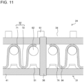
- Fig. 11 illustrates the configuration of the bridging header 24 according to a modification of Embodiment 1. As with Fig. 8 , Fig. 11 illustrates the section of the bridging header 24 taken in the longitudinal direction. As Fig. 11 illustrates, the bridging header 24 has a partition plate 36.
- the partition plate 36 is a flat plate-shaped part provided in the bridging header 24 so as to partition the bridging header 24 into portions in the longitudinal direction. Note that two or more partition plates 36 may be provided.
- the partition plate 36 separates the flow of the refrigerant on one side of the partition plate 36 from the flow of the refrigerant on the other side of the partition plate 36.
- the partition plate 36 has a thickness large enough not to be deformed even when there is a large difference in pressure between the refrigerants on one side and on the other side of the partition plate 36.
- the heat exchanger 7 can cause the refrigerants having different pressures to flow without the corrugated sheet 32 being deformed, as with the case where plural refrigerant pipes 4 constituting different refrigerant circuits are connected.
- Fig. 12 is a perspective view of a bridging header 124 according to Embodiment 2. Note that, in Fig. 12 , a covering plate 134 is transparent for an illustration purpose. Embodiment 2 differs from Embodiment 1 in that a corrugated sheet 132 has a corrugated-sheet hole 173 as Fig. 12 illustrates. In Embodiment 2, by the same parts as the parts of Embodiment 1 being denoted by the same references, the description thereof will be omitted, and differences from Embodiment 1 will be mainly described.
- Fig. 13 is a perspective view of the bridging header 124 according to Embodiment 2.
- Fig. 14 is a perspective view of the bridging header 124 according to Embodiment 2.
- the bridging header 124 has a base 131, the corrugated sheet 132, and the covering plate 134.
- the bridging header 124 has no end plate. Note that the bridging header 124 may have an end plate 33.
- Fig. 15 illustrates the configuration of the bridging header 124 according to Embodiment 2. As with Fig. 8 and Fig. 11 , Fig. 15 illustrates the section of the bridging header 124 taken in the longitudinal direction. As Fig. 12 and Fig. 15 illustrate, each of the planar portions 75 of the corrugated sheet 132 has the corrugated-sheet hole 173.
- the corrugated-sheet hole 173 is an opening through which refrigerant flows between the header flow passage 74 and the cover space 94. Thus, the cover space 94 is filled with the refrigerant that has flowed out from the header flow passage 74 through the corrugated-sheet hole 173.
- the header flow passage 74 is filled with the refrigerant flowing between the heat transfer tubes 21 facing one another in the lateral direction. That is, with the corrugated-sheet hole 173, the refrigerants in the header flow passage 74 and in the cover space 94 have uniform pressure. Note that the size of the corrugated-sheet hole 173 is set within a range in which the corrugated-sheet hole 173 is not closed by a molten metal when the fixation of a heat exchanger 107 is performed by brazing.
- the covering plate 134 is constituted by an upper covering plate 191 and a side covering plate 192.
- the upper covering plate 191 is a plate covering the upper side of the corrugated sheet 132.
- the upper covering plate 191 presses the corrugated sheet 132 toward the base 131.
- the side covering plate 192 is a plate covering a side portion of the corrugated sheet 132.
- the side covering plate 192 is fixed to the base 131 by being fitted into the plate hole 52 formed in the base 131. That is, the side covering plate 192 has a function similar to the function of the end plate 33 of Embodiment 1.
- the covering plate 134 may be constituted by only the upper covering plate 191 when the bridging header 124 has an end plate 33.
- Fig. 16 is a perspective view of the covering plate 134 according to Embodiment 2.
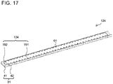
- Fig. 17 is a perspective view of the bridging header 124 according to Embodiment 2.
- the covering plate 134 may have a shape elongated toward end portions, in the longitudinal direction, of the bridging header 124. In this case, in the heat exchanger 107, the base 131 and the covering plate 134 can be fixed to one another regardless of the thickness of the covering plate 134.
- the corrugated sheet 132 has the corrugated-sheet hole 173.
- the cover space 94 is filled with the refrigerant that has flowed out from the header flow passage 74 through the corrugated-sheet hole 173.
- the header flow passage 74 is filled with the refrigerant flowing between the heat transfer tubes 21 facing one another in the lateral direction. That is, the refrigerants in the header flow passage 74 and in the cover space 94 have uniform pressure.
- the corrugated sheet 132 is further suppressed from being deformed by the pressure of the refrigerant flowing through the header flow passage 74 and is thus not required to be thickened. Consequently, regarding the heat exchanger 107, for example, the number of the heat transfer tubes 21 that are inserted into the bridging header 124 and a space between the heat transfer tubes 21 can be adjusted, and design flexibility can thus be increased.
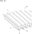
- Fig. 18 is a perspective view of a corrugated sheet 232 according to Embodiment 3.
- Embodiment 3 differs from Embodiment 1 in that a corrugated-sheet hole 273 is formed in an end portion, in the lateral direction, of the corrugated sheet 232 as Fig. 18 illustrates.
- Embodiment 3 by the same parts as the parts of Embodiment 1 being denoted by the same references, the description thereof will be omitted, and differences from Embodiment 1 will be mainly described.
- the corrugated-sheet hole 273 has a semicircular shape and is formed at each of both the end portions of the corrugated sheet 232 in the lateral direction.
- a portion of the refrigerant flowing through the header flow passage 74 flows out from the corrugated-sheet hole 273 positioned on one side and flows into the cover space 94
- a portion of the refrigerant flowing through the cover space 94 flows out from the corrugated-sheet hole 273 positioned on the other side and flows into the header flow passage 74. That is, the refrigerant circulates between the header flow passage 74 and the cover space 94.
- the refrigerants in the header flow passage 74 and in the cover space 94 have further uniform pressure.
- Fig. 19 illustrates a method of manufacturing a heat exchanger 207 according to Embodiment 3.
- Fig. 19 illustrates a bridging header 224 when the bridging header 224 is viewed in the longitudinal direction.
- Fig. 19 illustrates, for simple description, only the bottom base 41, the side base 42, and the corrugated sheet 232 are illustrated.
- the base 31 is a clad material, and a brazing material is pressure-bonded to an inner surface of the side base 42, that is, a surface to be in contact with the corrugated sheet 232.
- the bridging header 224 is disposed so that the side bases 42 are positioned above and below across the corrugated sheet 232, and brazing is performed.
- a corrugated-sheet hole 271 before brazing is referred to as a before-heating hole. That is, the corrugated-sheet hole 271 is a hole into which the before-heating hole is deformed by the brazing of the bridging header 224.
- a preferable dimension of the before-heating hole that is applicable in Embodiment 3 will be described.
- the before-heating hole is processed, for example, at the same time as uniformization of the length, in the lateral direction, of the corrugated sheet 232.
- the before-heating hole is formed in each of the upper region and the lower region of the corrugated sheet 232 and has a semicircular shape.
- the before-heating holes that is, the lower hole is referred to as a before-heating hole 280d, and the upper hole is referred to as a before-heating hole 280u.
- the width of the lower before-heating hole 280d that is, the width of a region in which the corrugated sheet 232 and the side base 42 on the lower side are not in contact with one another is referred to as a width Wd.
- the before-heating hole 280d has a semicircular shape, the distance from the side base 42 on the lower side to the outer edge of the lower before-heating hole 280d reaches a maximum distance of Wd/2 at a central portion Cd of the outer edge.
- the width of the upper before-heating hole 280u that is, the width of a region in which the corrugated sheet 232 and the side base 42 on the upper side are not in contact with one another is referred to as a width Wu. Because the before-heating hole 280u has a semicircular shape, the distance from the side base 42 on the upper side to the outer edge of the upper before-heating hole 280u reaches a maximum distance of Wu/2 at a central portion Cu of the outer edge.
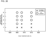
- Fig. 20 illustrates the presence or absence of closure of the before-heating hole 280d on the lower side caused by brazing according to Embodiment 3, for each of the widths Wd of the before-heating holes and for each of the peak temperatures.
- Fig. 21 illustrates the presence or absence of closure of the before-heating hole 280u on the upper side caused by brazing according to Embodiment 3, for each of the widths Wu of the before-heating holes and for each of the peak temperatures.
- Fig. 20 illustrates the presence or absence of closure of the before-heating hole 280d on the lower side caused by brazing according to Embodiment 3, for each of the widths Wd of the before-heating holes and for each of the peak temperatures.
- Fig. 21 illustrates the presence or absence of closure of the before-heating hole 280u on the upper side caused by brazing according to Embodiment 3, for each of the widths Wu of the before-heating holes and for each of the peak temperatures.
- Fig. 19 illustrates, the presence or absence of closure of the before-heating hole when brazing is performed with the side bases 42 of clad material being positioned above and below the corrugated sheet 232 is verified for each of the widths of the before-heating holes and for each of the peak temperatures, and the presence or absence of closure of the before-heating hole is plotted.
- Fig. 20 illustrates the case of the lower before-heating hole 280d
- Fig. 21 illustrates the case of the upper before-heating hole 280u.
- Fig. 20 and Fig. 21 illustrate, it has been found that even a before-heating hole whose width W is larger is closed as the peak temperature of brazing is increased. It has also been found that there is a difference in a width with which an opening is closed, between the upper before-heating hole and the lower before-heating hole. Specifically, when heating is performed at the same peak temperature, in the case of the lower before-heating hole 280d, closure occurs in a before-heating hole whose width Wd is larger, compared with the case of the upper before-heating hole 280u.
- the difference between the cases is caused by an incident in which, when the molten clad material flowing, by gravitation, along the corrugated sheet 232, the molten clad material flows into the lower before-heating hole 280d formed at a position below the upper before-heating hole 280u.
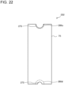
- Fig. 22 is a side view of the corrugated sheet 232 after brazing according to Embodiment 3.
- Fig. 22 illustrates the corrugated sheet 232 when the corrugated sheet 232 is viewed in the longitudinal direction. The broken line represents a before-heating hole.
- Fig. 22 illustrates, even when before-heating holes having the same width are formed in two end portions, in the lateral direction, of the corrugated sheet 232 before brazing, the corrugated-sheet holes 273 after brazing have different widths depending on the orientation of the bridging header 224 during brazing.
- the before-heating hole 280u positioned on the upper side during brazing is hardly closed even when having a width Wu smaller than the width of the before-heating hole 280d positioned on the lower side.
- the width Wu has room for reduction by 1 mm to reach a width with which closure is caused, compared with the lower before-heating hole 280d that is brazed at the same peak temperature.
- the width Wu of the before-heating hole 280u positioned on the upper side may be 1 mm smaller than the width of the before-heating hole 280d positioned on the lower side.
- the before-heating hole is formed in the planar portion 75 so as not to extend over a rounded portion of the corrugated sheet 232.
- L is a dimension, in the lateral direction, of the planar portion 75 of the corrugated sheet 232
- the before-heating hole can be within the range from 1 mm to L - processing tolerance mm.
- the processing tolerance is, for example, 0.5 mm.
- the corrugated-sheet holes 273 are formed in both the end portions, in the lateral direction, of the corrugated sheet 232.
- a portion of the refrigerant flowing through the header flow passage 74 flows out from the corrugated-sheet hole 273 positioned on one side and flows into the cover space 94, and a portion of the refrigerant flowing through the cover space 94 flows out from the corrugated-sheet hole 273 positioned on the other side and flows into the header flow passage 74. That is, the refrigerant circulates between the header flow passage 74 and the cover space 94, and the pressure of the refrigerant is further maintained uniform.
- the corrugated sheet 232 is further suppressed from being deformed by the pressure of the refrigerant flowing through the header flow passage 74 and is thus not required to be thickened. Consequently, regarding the heat exchanger 207, for example, the number of the heat transfer tubes 21 that are inserted into the bridging header 224 and a space between the heat transfer tubes 21 can be adjusted, and design flexibility can thus be increased.
- the corrugated-sheet hole 273 may be processed at the same time as the processing performed when the length, in the lateral direction, of the corrugated sheet 232 is uniformized. In this case, regarding the heat exchanger 207, the time and effort for processing can be reduced.
- the width Wu of the before-heating hole 280u positioned on the upper side during brazing is smaller than the width Wd of the before-heating hole 280d positioned on the lower side during brazing.
- the before-heating hole can be formed within the range from 1 mm to L - processing tolerance mm.
- the bonding area between the corrugated sheet 232 and the side base 42 can be ensured, and the bonding strength between the corrugated sheet 232 and the base 31 can thus be suppressed from being decreased.
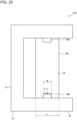
- Fig. 23 illustrates a method of manufacturing a heat exchanger 307 according to Embodiment 4.
- Fig. 23 illustrates a bridging header 324 when the bridging header 324 is viewed in the longitudinal direction.
- the method of manufacturing the heat exchanger 307 of Embodiment 4 differs from the method of manufacturing the heat exchanger of Embodiment 3 in that a corrugated sheet 332 has a before-heating hole 380 having a rectangular shape as Fig. 23 illustrates.
- Embodiment 4 by the same parts as the parts of Embodiment 3 being denoted by the same references, the description thereof will be omitted, and differences from Embodiment 3 will be mainly described.
- the before-heating hole 380 has a rectangular shape. Note that, although, in Fig. 23 , the bridging header 324 is disposed so that the side bases 42 are positioned above and below across the corrugated sheet 332, the orientation of the bridging header 324 is not limited during brazing in the method of manufacturing the heat exchanger 307 of Embodiment 4. In most cases, in brazing, a molten brazing material forms a fillet along the outer edge of the before-heating hole 380 so as to fill the before-heating hole 380 with a contact point between the outer edge of the before-heating hole 380 and the side base 42 being a starting point.
- the space between the outer edge of the before-heating hole 380 and the side base 42 reaches a maximum size only at a central portion C of the outer edge of the before-heating hole 380.
- the space between the outer edge of the before-heating hole 380 and the side base 42 reaches a maximum size at any point along a side F, of the outer edge of the before-heating hole 380, facing the inner surface of the side base 42.
- the space between the before-heating hole 380 and the side base 42 can be widened as a whole compared with the case of the semicircular before-heating hole when the width of the before-heating hole 380 is the same in both the cases, and the maximum space between the before-heating hole 380 and the side base 42 is the same between both the cases.
- the width W of the rectangular before-heating hole 380 can be within the range from 1 mm to L - processing tolerance mm, as with the diameter of the semicircular before-heating hole 380 in Embodiment 3.
- the processing tolerance is, for example, 0.5 mm.
- the space between the before-heating hole 380 and the side base 42 can be widened as a whole by the before-heating hole 380 being formed into a rectangular shape.
- the before-heating hole 380 can be suppressed from being closed after brazing, the bonding area between the corrugated sheet 232 and the side base 42 can be ensured, and the bonding strength between the corrugated sheet 232 and the base 31 can thus be suppressed from being decreased.
- Fig. 24 is a perspective view of a bridging header 424 according to Embodiment 5.
- Fig. 25 is a perspective view of the bridging header 424 according to Embodiment 5. Note that, in Fig. 25 , a covering plate 434 is transparent, and the corrugated sheet 32 is semitransparent.
- Fig. 26 is a perspective view of a base 431 according to Embodiment 5. Embodiment 5 differs from Embodiment 1 in that the base 431 has a cutout 463 as Figs. 24 to 26 illustrate. In Embodiment 5, by the same parts as the parts of Embodiment 1 being denoted by the same references, the description thereof will be omitted, and differences from Embodiment 1 will be mainly described.
- a heat exchanger 407 of Embodiment 5 is provided in the outdoor unit 2 so that, for example, a bottom base 441 serves as the lower side of the base 431.
- a side base 442 of Embodiment 5 has the cutouts 463 having a semicircular shape on both sides of each of the claw portions 61. The depth of each of the cutouts 463 is adjusted so that a lower end portion of the cutout 463 is positioned below the upper surface of the covering plate 434.
- the side base 442 when the side base 442 is provided at a position lower than the upper surface of the covering plate 434 throughout the length of the side base 442 for placing priority on drainage, the contact surface between the base 431 and the covering plate 434 cannot be sufficiently ensured, and insufficient brazing may be caused. In this case, the pressure resistance of the bridging header 424 may be decreased.
- the cutouts 463 are provided only beside both sides of the claw portion 61, and the pressure resistance and the drainage properties of the bridging header 424 can thereby be compatible with one another.
- each of the plural claw portions 61 of the side base 442 is bent at the base thereof for pressing the covering plate 434 toward the corrugated sheet 32.
- the bending workability of the claw portion 61 is improved by the cutouts 463 being provided beside both sides of the claw portions 61.
- the side base 442 has plural plate-catching portions 453. On both end portions, in the longitudinal direction, of the side base 442, two plate-catching portions 453 are provided per end portion and protrude from the inner wall surface of the side base 442.
- the bottom base 441 has no plate hole into which an end plate 433 is fitted.
- the end plate 433 is fixed by an end of the end plate 433 being held between the two plate-catching portions 453.
- the end plate 433 can be fixed while a pressure resistance on per with the pressure resistance when the end plate 433 is fitted into the plate hole 52 of Embodiment 1 is ensured.
- the plate-catching portion 453 of Embodiment 5 may be provided for the base 31 of Embodiment 1 as a substitute for a part of the base 31 or as an additional part to the base 31.
- the cutout 463 of Embodiment 5 may be formed in the base of any one of Embodiments 2 to 4.
Landscapes
- Engineering & Computer Science (AREA)
- Physics & Mathematics (AREA)
- Thermal Sciences (AREA)
- Mechanical Engineering (AREA)
- General Engineering & Computer Science (AREA)
- Geometry (AREA)
- Heat-Exchange Devices With Radiators And Conduit Assemblies (AREA)
Abstract
Description
- The present disclosure relates a heat exchanger having a bridging header and a method of manufacturing a heat exchanger.
- There has been known a heat exchanger having pairs of mutually facing heat transfer tubes. In the pairs, the heat transfer tubes in a first row and the heat transfer tubes in a second row extend parallel to one another. Regarding such a heat exchanger, a bridging header into which end portions of the heat transfer tubes are inserted has flow passages. In each of the flow passages, refrigerant flows only between a pair of the heat transfer tubes. That is, in the bridging header, the refrigerant that has flowed into the bridging header from a heat transfer tube arranged in the first row does not merge with the flow of the refrigerant that has flowed into the bridging header from another heat transfer tube arranged in the first row.
Patent Literature 1 discloses a heat exchanger having a base into which heat transfer tubes are inserted and a bridging header constituted by a corrugated sheet that is provided on the base and that has a wavy shape in which semicircular column portions are continuously formed. Each of the semicircular column portions of the corrugated sheet covers points at which the paired heat transfer tubes are inserted and forms a flow passage between the semicircular column portion and the base. - Patent Literature 1:
Japanese Patent No. 5786877 - However, the corrugated sheet of the heat exchanger of
Patent Literature 1 is required to be thickened so as not to be deformed by the pressure of the refrigerant flowing through the bridging header. In most cases, a thickened corrugated sheet is likely to interfere with the inserted heat transfer tube and is likely to cover, in a hindering way, a point at which the heat transfer tube is inserted. In the heat exchanger of thePatent Literature 1, because being thickened, the corrugated sheet reduces a region, in the base, into which the heat transfer tubes can be inserted. Thus, regarding the heat exchanger ofPatent Literature 1, for example, the number of the heat transfer tubes that are inserted into the bridging header and a space between the heat transfer tubes are limited, and design flexibility is thus decreased. - The present disclosure has been made to solve such an above-described problem and provides: a heat exchanger enabling adjustment of, for example, the number of the heat transfer tubes that are inserted into a bridging header and a space between the heat transfer tubes and thus enabling increase in design flexibility; and a method of manufacturing the heat exchanger.
- A heat exchanger of one embodiment of the present disclosure has: a heat transfer tube group made up of plural heat transfer tubes each of which has, inside the heat transfer tube, a flow passage through which refrigerant flows, the plural heat transfer tubes that are arranged in a lateral direction being arranged in a longitudinal direction so as to form plural rows; a fin provided on the heat transfer tubes and facilitating heat exchange between refrigerant flowing inside the heat transfer tubes and air; and a bridging header into which end portions of the heat transfer tubes are inserted and that causes refrigerant to flow between the heat transfer tubes arranged in a lateral direction of the heat transfer tube group. The bridging header has a base having a flat plate shape and having insertion holes into which respective ones of end portions of the plurality of heat transfer tubes are inserted. The bridging header also has a corrugated sheet being a plate having a shape of a wave in which crest portions and valley portions are continuously formed, each of the crest portions being provided so as to cover a pair of the insertion holes arranged in a lateral direction, the valley portions being in contact with the base on both sides of each of the insertion holes in a longitudinal direction of the base, the corrugated sheet forming, between the corrugated sheet and the base, a header flow passage, through which refrigerant flows, for every the heat transfer tubes arranged in a lateral direction of the heat transfer tube group. The bridging header also has a covering plate covering the corrugated sheet and pressing the corrugated sheet toward the base.
- A method of manufacturing a heat exchanger of another embodiment of the present disclosure includes: assembling: a heat transfer tube group made up of plural heat transfer tubes each of which has, inside the heat transfer tube, a flow passage through which refrigerant flows, the plural heat transfer tubes that are arranged in a lateral direction being arranged in a longitudinal direction so as to form plural rows; a fin provided on the heat transfer tubes and facilitating heat exchange between refrigerant flowing inside the heat transfer tubes and air; and a bridging header into which end portions of the heat transfer tubes are inserted and that causes refrigerant to flow between the heat transfer tubes arranged in a lateral direction of the heat transfer tube group. The method also includes performing brazing of the heat transfer tube group, the fin, and the bridging header. The assembling includes: fitting the corrugated sheet of the bridging header into the base, of the bridging header, having insertion holes into which respective ones of end portions of the plurality of heat transfer tubes are inserted, the fitting being performed so that, in the corrugated sheet being a plate having a shape of a wave in which crest portions and valley portions are continuously formed, each of the crest portions covers a pair of the insertion holes arranged in a lateral direction, and the valley portions are in contact with the base on both sides of each of the insertion holes in a longitudinal direction of the base; and carrying out attachment of a covering plate so that the covering plate covers the corrugated sheet.
- According to an embodiment of the present disclosure, the bridging header has the covering plate that presses the corrugated sheet toward the base. Thus, the corrugated sheet is suppressed from being deformed by the pressure of the refrigerant flowing through the bridging header. That is, for suppressing the corrugated sheet from being deformed by the pressure of the refrigerant flowing through the bridging header, the corrugated sheet is not required to be thickened. Consequently, regarding the heat exchanger, for example, the number of the heat transfer tubes that are inserted into the bridging header and a space between the heat transfer tubes can be adjusted, and design flexibility can thus be increased.
-
- [
Fig. 1] Fig. 1 is a circuit diagram of an air-conditioning apparatus 1 according toEmbodiment 1. - [
Fig. 2] Fig. 2 is a perspective view of aheat exchanger 7 according toEmbodiment 1. - [
Fig. 3] Fig. 3 is a side view of abridging header 24 according toEmbodiment 1. - [
Fig. 4] Fig. 4 is a perspective view of thebridging header 24 according toEmbodiment 1. - [
Fig. 5] Fig. 5 is a perspective view of thebridging header 24 according toEmbodiment 1. - [
Fig. 6] Fig. 6 is a perspective view of abase 31 according toEmbodiment 1. - [
Fig. 7] Fig. 7 is a perspective view of thebase 31 according to Embodiment 1. - [
Fig. 8] Fig. 8 illustrates the configuration of thebridging header 24 according toEmbodiment 1. - [
Fig. 9] Fig. 9 is a perspective view of thebridging header 24 according toEmbodiment 1. - [
Fig. 10] Fig. 10 is a perspective view of thebridging header 24 according to a modification ofEmbodiment 1. - [
Fig. 11] Fig. 11 illustrates the configuration of thebridging header 24 according to a modification ofEmbodiment 1. - [
Fig. 12] Fig. 12 is a perspective view of abridging header 124 according toEmbodiment 2. - [
Fig. 13] Fig. 13 is a perspective view of thebridging header 124 according toEmbodiment 2. - [
Fig. 14] Fig. 14 is a perspective view of thebridging header 124 according toEmbodiment 2. - [
Fig. 15] Fig. 15 illustrates the configuration of thebridging header 124 according toEmbodiment 2. - [
Fig. 16] Fig. 16 is a perspective view of acovering plate 134 according to Embodiment 2. - [
Fig. 17] Fig. 17 is a perspective view of thebridging header 124 according toEmbodiment 2. - [
Fig. 18] Fig. 18 is a perspective view of acorrugated sheet 232 according toEmbodiment 3. - [
Fig. 19] Fig. 19 illustrates a method of manufacturing a heat exchanger 207 according to Embodiment 3. - [
Fig. 20] Fig. 20 illustrates the presence or absence of closure of a before-heating hole 280d on the lower side caused by brazing according toEmbodiment 3, for each of the widths Wd of the before-heating holes and for each of the peak temperatures. - [
Fig. 21] Fig. 21 illustrates the presence or absence of closure of a before-heating hole 280u on the upper side caused by brazing according toEmbodiment 3, for each of the widths Wu of the before-heating holes and for each of the peak temperatures. - [
Fig. 22] Fig. 22 is a side view of thecorrugated sheet 232 after brazing according to Embodiment 3. - [
Fig. 23] Fig. 23 illustrates a method of manufacturing a heat exchanger 307 according to Embodiment 4. - [
Fig. 24] Fig. 24 is a perspective view of abridging header 424 according to Embodiment 5. - [
Fig. 25] Fig. 25 is a perspective view of thebridging header 424 according to Embodiment 5. - [
Fig. 26] Fig. 26 is a perspective view of abase 431 according to Embodiment 5. Description of Embodiments - Hereinafter, an air-
conditioning apparatus 1 provided with aheat exchanger 7 according toEmbodiment 1 will be described with reference to the drawings. In addition, theheat exchanger 7 may be provided for an apparatus other than the air-conditioning apparatus 1.Fig. 1 is a circuit diagram of the air-conditioning apparatus 1 according toEmbodiment 1. AsFig. 1 illustrates, the air-conditioning apparatus 1 has anoutdoor unit 2, anindoor unit 3, and arefrigerant pipe 4. Note that, althoughFig. 1 illustrates the singleindoor unit 3, the number of theindoor units 3 may be two or more. - The
outdoor unit 2 includes acompressor 5, a flow-switchingdevice 6, theheat exchanger 7, an outdoor fan 8, and anexpansion unit 9. Theindoor unit 3 includes anindoor heat exchanger 11 and an indoor fan 12. Therefrigerant pipe 4 constitutes a refrigerant circuit by connecting thecompressor 5, the flow-switchingdevice 6, theheat exchanger 7, theexpansion unit 9, and theindoor heat exchanger 11 to one another and by allowing refrigerant to flow inside therefrigerant pipe 4. - The
compressor 5 sucks low-temperature and low-pressure refrigerant, compresses the sucked refrigerant to bring the refrigerant into a high-temperature and high-pressure state, and discharges the refrigerant. The flow-switchingdevice 6 switches flowing directions of refrigerant in the refrigerant circuit and is, for example, a four-way valve. Theheat exchanger 7 exchanges heat between refrigerant and outdoor air. Theheat exchanger 7 operates as a condenser during a cooling operation and operates as an evaporator during a heating operation. The outdoor fan 8 is a device for sending outdoor air to theheat exchanger 7. Theexpansion unit 9 is a pressure-reducing valve or an expansion valve for reducing the pressure of refrigerant to expand the refrigerant. - The
indoor heat exchanger 11 exchanges heat between indoor air and refrigerant. Theindoor heat exchanger 11 operates as an evaporator during the cooling operation and operates as a condenser during the heating operation. The indoor fan 12 is a device for sending indoor air to theindoor heat exchanger 11. - Here, an operation of the air-
conditioning apparatus 1 will be described. First, the cooling operation will be described. In the cooling operation, the refrigerant sucked into thecompressor 5 is compressed by thecompressor 5, and the refrigerant that has turned into a high-temperature and high-pressure gas state is discharged from thecompressor 5. The high-temperature and high-pressure gas state refrigerant that has been discharged from thecompressor 5 passes through the flow-switchingdevice 6 and flows into theheat exchanger 7 operating as a condenser. The refrigerant that has flowed into theheat exchanger 7 exchanges heat with the outdoor air sent by the outdoor fan 8 and is thus condensed to be liquefied. The refrigerant in a liquid state flows into theexpansion unit 9 and is reduced in pressure and expanded to turn into a low-temperature and low-pressure two-phase gas-liquid state. The refrigerant in a gas-liquid two-phase state flows into theindoor heat exchanger 11 operating as an evaporator. The refrigerant that has flowed into theindoor heat exchanger 11 exchanges heat with the indoor air sent by the indoor fan 12 and is thus evaporated to be gasified. At this time, the indoor air is cooled and air cooling is performed in a room. Subsequently, the evaporated refrigerant in a low-temperature and low-pressure gas state passes through the flow-switchingdevice 6 and is sucked into thecompressor 5. - Next, the heating operation will be described. In the heating operation, the refrigerant sucked into the
compressor 5 is compressed by thecompressor 5, and the refrigerant that has turned into a high-temperature and high-pressure gas state is discharged from thecompressor 5. The high-temperature and high-pressure gas state refrigerant that has been discharged from thecompressor 5 passes through the flow-switchingdevice 6 and flows into theindoor heat exchanger 11 operating as a condenser. The refrigerant that has flowed into theindoor heat exchanger 11 exchanges heat with the indoor air sent by the indoor fan 12 and is thus condensed to be liquefied. At this time, the indoor air is heated and air heating is performed in the room. The refrigerant in a liquid state flows into theexpansion unit 9 and is reduced in pressure and expanded to turn into a low-temperature and low-pressure two-phase gas-liquid state. The refrigerant in a gas-liquid two-phase state flows into theheat exchanger 7 operating as an evaporator. The refrigerant that has flowed into theheat exchanger 7 exchanges heat with the outdoor air sent by the outdoor fan 8 and is thus evaporated to be gasified. Subsequently, the evaporated refrigerant in a low-temperature and low-pressure gas state passes through the flow-switchingdevice 6 and is sucked into thecompressor 5. -
Fig. 2 is a perspective view of theheat exchanger 7 according toEmbodiment 1. Here, the configuration of theheat exchanger 7 will be described in detail. Theheat exchanger 7 has a heattransfer tube group 20, afin 22, a firstlower header 23, a bridgingheader 24, and a secondlower header 25. Note that a configuration similar to the configuration of theheat exchanger 7 may be applied to theindoor heat exchanger 11. - The heat
transfer tube group 20 is constituted by pluralheat transfer tubes 21. Theheat transfer tubes 21 arranged in the lateral direction are arranged in the longitudinal direction so as to form plural rows. Theheat transfer tubes 21 are, for example, flat tubes and have plural flow passages (not illustrated) inside which refrigerant flows. InEmbodiment 1, each of theheat transfer tubes 21 extends in the vertical direction. Note that theheat transfer tube 21 may alternatively extend in a direction other than the vertical direction. In this case, other parts of theheat exchanger 7 are also assembled based on the direction where theheat transfer tube 21 extends. In addition, inEmbodiment 1, theheat transfer tubes 21 form two rows that are a first row and a second row extending parallel to one another. Note that theheat transfer tubes 21 may extend in three or more rows. Thefin 22, which is, for example, a corrugated fin, is provided on theheat transfer tubes 21 and facilitates heat exchange between the refrigerant flowing inside theheat transfer tubes 21 and air. - The first
lower header 23 is a header into which an end portion on one side of each of theheat transfer tubes 21 arranged in the first row is inserted. Therefrigerant pipe 4 is connected to the firstlower header 23. The firstlower header 23 distributes the refrigerant that has flowed into the firstlower header 23 from therefrigerant pipe 4 to theheat transfer tubes 21 arranged in the first row. The firstlower header 23 also causes the refrigerant that has merged with the refrigerant flow in the firstlower header 23 from theheat transfer tubes 21 arranged in the first row to flow out into therefrigerant pipe 4. - The bridging
header 24 is a header that faces the firstlower header 23 and the secondlower header 25 and into which an end portion on the other side of each of theheat transfer tubes 21 arranged in the first row and in the second row is inserted. The bridgingheader 24 distributes the refrigerant that has merged with the refrigerant flow in the bridgingheader 24 from aheat transfer tube 21 arranged in the first row to aheat transfer tube 21 arranged in the second row. The bridgingheader 24 also distributes the refrigerant that has merged with the refrigerant flow in the bridgingheader 24 from theheat transfer tube 21 arranged in the second row to theheat transfer tube 21 arranged in the first row and facing, in the lateral direction, theheat transfer tube 21 arranged in the second row. -
Fig. 3 is a side view of the bridgingheader 24 according toEmbodiment 1.Fig. 3 illustrates the bridgingheader 24, when the bridgingheader 24 is viewed in the longitudinal direction.Fig. 4 is a perspective view of the bridgingheader 24 according toEmbodiment 1.Fig. 5 is a perspective view of the bridgingheader 24 according toEmbodiment 1. Note that, inFig. 5 , a coveringplate 34 is transparent for an illustration purpose. AsFigs. 3 to 5 illustrate, the bridgingheader 24 has abase 31, acorrugated sheet 32, the coveringplate 34, and anend plate 33. -
Fig. 6 is a perspective view of the base 31 according toEmbodiment 1.Fig. 7 is a perspective view of the base 31 according toEmbodiment 1. AsFig. 6 andFig. 7 illustrate, thebase 31 is a flat plate-shaped part into which theheat transfer tubes 21 are inserted. Thebase 31 is constituted by abottom base 41 and aside base 42. Thebottom base 41 is a plate-shaped part constituting the bottom of thebase 31 and having plural insertion holes 51 and aplate hole 52. The insertion holes 51 are openings into which the end portions of theheat transfer tubes 21 are inserted. InEmbodiment 1, regarding the insertion holes 51, two holes are arranged in the lateral direction and are paired. The insertion holes 51 are further arranged, in two rows, in the longitudinal direction. Theplate hole 52 is an opening into which theend plate 33 is fitted. Theplate hole 52 is opened substantially throughout the width of thebottom base 41 in the lateral direction. Theside base 42 is a plate-shaped part constituting a side of thebase 31 and extending, from an edge portion of thebottom base 41, along an edge of thecorrugated sheet 32 extending in the longitudinal direction. Twoside bases 42 are provided in the longitudinal direction of theheat exchanger 7. Each of the side bases 42 hasplural claw portions 61 and plural catchingprotrusions 62. -
Fig. 8 illustrates the configuration of the bridgingheader 24 according toEmbodiment 1.Fig. 9 is a perspective view of the bridgingheader 24 according toEmbodiment 1.Fig. 8 illustrates the section of the bridgingheader 24 taken in the A-A direction illustrated inFig. 3 . That is,Fig. 8 illustrates the section of the bridgingheader 24 taken in the longitudinal direction. Note that, inFig. 9 , the coveringplate 34 is transparent, and thecorrugated sheet 32 is semitransparent. AsFig. 4 andFig. 5 illustrate, each of theclaw portions 61 is a claw-shaped part protruding from an upper end portion of theside base 42 toward the coveringplate 34. Theclaw portion 61 is in contact with a surface of the coveringplate 34 facing thecorrugated sheet 32 and presses the coveringplate 34 toward thecorrugated sheet 32. AsFig. 8 andFig. 9 illustrates, each of the catchingprotrusions 62 is a substantially hollow cylindrical part protruding from an inner wall surface of theside base 42. The catchingprotrusions 62 catches upper end portions, in the lateral direction,crest portions 71 of thecorrugated sheet 32, which will be described later. Note that theside base 42 may have no catchingprotrusion 62. - As
Fig. 5 andFig. 8 illustrate, thecorrugated sheet 32 is a sheet having a shape of a wave in which thecrest portions 71 andvalley portions 72 are continuously formed. Each of thecrest portions 71 forms an arch shape in an upper region of thecorrugated sheet 32. Each of thevalley portions 72 forms an arch shape in a lower region of thecorrugated sheet 32. Each of thecrest portions 71 covers a pair of the insertion holes 51 arranged in the lateral direction of the heattransfer tube group 20. That is, aheader flow passage 74 through which refrigerant flows is formed, between each of thecrest portions 71 and thebase 31, for every theheat transfer tubes 21 arranged in the lateral direction of the heattransfer tube group 20. In addition, the uppermost portion of thecrest portion 71 is in contact with the coveringplate 34. In the longitudinal direction of the bridgingheader 24, the lowermost portions of thevalley portions 72 are in contact with the base 31 on both sides of each of the insertion holes 51. In addition, a planar region of thecorrugated sheet 32, that is, a portion of the corrugated sheet, other than the rounded portion near the peak of thecrest portion 71 and the rounded portion near the peak of thevalley portion 72, is referred to as aplanar portion 75. Thecorrugated sheet 32 has pluralplanar portions 75 separated from one another by the rounded shapes near the peaks of thecrest portions 71 and thevalley portions 72. - The
end plate 33 is a flat plate-shaped part provided beside thecorrugated sheet 32. Theend plate 33 is fixed to thebase 31 by being fitted into theplate hole 52 formed in thebase 31. Theend plate 33 supports a side portion of the coveringplate 34. Theend plate 33 has anengagement protrusion 81. Theengagement protrusion 81 protrudes upward from the upper end face of theend plate 33. Theengagement protrusion 81 is engaged with anengagement hole 93 of the coveringplate 34, which will be described later. Note that theend plate 33 may have noengagement protrusion 81. - The covering
plate 34 is a flat plate-shaped part covering thecorrugated sheet 32. The coveringplate 34 is provided, in an upper region of the bridgingheader 24, between two side bases 42. In addition, the coveringplate 34 presses thecorrugated sheet 32 toward thebase 31. Moreover, the coveringplate 34 forms acover space 94 between the coveringplate 34 and thecorrugated sheet 32. A side portion of the coveringplate 34 has theengagement hole 93. Theengagement hole 93 is an opening into which theengagement protrusion 81 of theend plate 33 is inserted. - The second
lower header 25 is a header that is arranged parallel to the firstlower header 23 and into which an end portion on one side of each of theheat transfer tubes 21 arranged in the second row is inserted. Therefrigerant pipe 4 is connected to the secondlower header 25. The secondlower header 25 distributes the refrigerant that has flowed into the secondlower header 25 from therefrigerant pipe 4 to theheat transfer tubes 21 arranged in the second row. The secondlower header 25 also causes the refrigerant that has merged with the refrigerant flow in the secondlower header 25 from theheat transfer tubes 21 arranged in the second row to flow out into therefrigerant pipe 4. Note that, regarding theheat exchanger 7, the firstlower header 23 and the secondlower header 25 may be formed as one body and may have, in a central portion, a partition part (not illustrated) that partitions the inner space of the firstlower header 23 and the secondlower header 25. - Here, a method of manufacturing the
heat exchanger 7 will be described. Note that each of thebase 31 of the bridgingheader 24, thefin 22, the firstlower header 23, and the secondlower header 25 is made of a clad material formed by pressure-bonding of a metal for brazing being performed. First, each of the parts of theheat exchanger 7 is formed into a predetermined shape. Here, for example, thecorrugated sheet 32 is cut out as a rectangular flat plate having a predetermined size and is then processed into a wavy shape. Regarding thebase 31, the insertion holes 51 and theengagement protrusions 81, for example, are formed, and thebase 31 is then bent to have thebottom base 41 and the side bases 42. - Next, each of the parts of the
heat exchanger 7 is assembled. Specifically, first, thecorrugated sheet 32 is fitted in thebase 31 of the bridgingheader 24. Due to such assembly, each of thecrest portions 71 covers a pair of the insertion holes 51 arranged in the lateral direction, and, in the longitudinal direction of thebase 31, thevalley portions 72 come into contact with the base 31 on both sides of each of the insertion holes 51. Next, theend plate 33 is inserted into theplate hole 52 of thebase 31. Subsequently, the coveringplate 34 is attached to the base 31 so as to cover thecorrugated sheet 32. At this time, theengagement protrusion 81 of theend plate 33 is inserted into theengagement hole 93 of the coveringplate 34. Theclaw portions 61 of the side bases 42 are bent, and the bridgingheader 24 is thus assembled. - Furthermore, the
fin 22 is provided between each two of the pluralheat transfer tubes 21, and theheat transfer tubes 21 are inserted into the bridgingheader 124, into the firstlower header 23, and into the secondlower header 25. Thus, theentire heat exchanger 107 is assembled. The assembledheat exchanger 107 is then placed in a brazing apparatus and is subjected to brazing. The upper limit brazing temperature may be set at a temperature that is higher than the solidus temperature of an Al-Si alloy, which is typically used as a brazing material, and at which an Al base metal is not melted, that is, for example, a temperature higher than 580 degrees C and lower than 630 degrees C. Due to such brazing, the clad material being subjected to pressure-bonding is melted, and each of the parts of theheat exchanger 7 is fixed. In the above-described way, theheat exchanger 7 is manufactured. - Note that the sequence of the processes of the above-described manufacturing method may be appropriately changed. For example, only the bridging
header 24 may be fixed, by brazing, ahead. In addition, although the example of thebase 31, of the bridgingheader 24, made of a clad material has been described, theend plate 33 and the coveringplate 34, in addition to thebase 31, may also be made of a clad material. Alternatively, only thecorrugated sheet 32 may be made of a clad material. In addition to the bridgingheader 24, in theentire heat exchanger 7, the selection of which part is made of a clad material may be adjusted appropriately. - According to
Embodiment 1, the bridgingheader 24 has the coveringplate 34 pressing thecorrugated sheet 32 toward thebase 31. Thus, thecorrugated sheet 32 is suppressed from being deformed by the pressure of the refrigerant flowing through the bridgingheader 24. That is, for suppressing thecorrugated sheet 32 from being deformed by the pressure of the refrigerant flowing through the bridgingheader 24, thecorrugated sheet 32 is not required to be thickened. Consequently, regarding theheat exchanger 7, for example, the number of theheat transfer tubes 21 that are inserted into the bridgingheader 24 and a space between theheat transfer tubes 21 can be adjusted, and design flexibility can thus be increased. - More specifically, the covering
plate 34 presses each of thecrest portions 71 of thecorrugated sheet 32. Due to such pressing, thecrest portions 71 are uniform in height even when tolerances on the heights of thecrest portions 71 arise through the manufacturing of thecorrugated sheet 32. That is, thecorrugated sheet 32 has, at any point thereof, a constant strength against the refrigerant flowing through each of theheader flow passages 74, thereby having less points at which thecorrugated sheet 32 is likely to be broken. Thus, theheat exchanger 7 is hardly broken by the pressure of the refrigerant flowing through the bridgingheader 24. - In addition, according to
Embodiment 1, theside base 42 has theclaw portions 61. Each of theclaw portions 61 is in contact with a surface of the coveringplate 34 facing thecorrugated sheet 32 and presses the coveringplate 34 toward thecorrugated sheet 32. Thus, because being further strongly pressed by the coveringplate 34, thecorrugated sheet 32 is further suppressed from being deformed by the pressure of the refrigerant flowing through the bridgingheader 24. That is, thecorrugated sheet 32 is not required to be thickened. Consequently, regarding theheat exchanger 7, for example, the number of theheat transfer tubes 21 that are inserted into the bridgingheader 24 and a space between theheat transfer tubes 21 can be adjusted, and design flexibility can thus be increased. - Furthermore, according to
Embodiment 1, theside base 42 has the catchingprotrusion 62. In most cases, when a corrugated sheet is long, there may be a crest portion, of the corrugated sheet, being at a position at which the crest portion does not cover an insertion hole due to tolerances, on the corrugated sheet, arising in the longitudinal direction. Here, theside base 42 ofEmbodiment 1 has the catchingprotrusion 62. Thus, with the bridgingheader 24, it is possible to determine accurately the position at which thecorrugated sheet 32 is provided and to fix the corrugated sheet, by end portions, in the lateral direction, of thecrest portion 71 being caught by the catchingprotrusions 62. Accordingly, theheat exchanger 7 ofEmbodiment 1 can be upsized when, for example, a large number of theheat transfer tubes 21 are provided, and a longcorrugated sheet 32 is thus required. -
Fig. 10 is a perspective view of the bridgingheader 24 according to a modification ofEmbodiment 1. AsFig. 10 illustrates, the bridgingheader 24 has aleg portion 35. Theleg portion 35 is a plate-shaped part extending in the vertical direction of theheat exchanger 7 and supporting theheat exchanger 7. -
Fig. 11 illustrates the configuration of the bridgingheader 24 according to a modification ofEmbodiment 1. As withFig. 8 ,Fig. 11 illustrates the section of the bridgingheader 24 taken in the longitudinal direction. AsFig. 11 illustrates, the bridgingheader 24 has apartition plate 36. Thepartition plate 36 is a flat plate-shaped part provided in the bridgingheader 24 so as to partition the bridgingheader 24 into portions in the longitudinal direction. Note that two ormore partition plates 36 may be provided. Thepartition plate 36 separates the flow of the refrigerant on one side of thepartition plate 36 from the flow of the refrigerant on the other side of thepartition plate 36. In addition, thepartition plate 36 has a thickness large enough not to be deformed even when there is a large difference in pressure between the refrigerants on one side and on the other side of thepartition plate 36. Thus, in regions on both sides of thepartition plate 36, theheat exchanger 7 can cause the refrigerants having different pressures to flow without thecorrugated sheet 32 being deformed, as with the case where pluralrefrigerant pipes 4 constituting different refrigerant circuits are connected. -
Fig. 12 is a perspective view of abridging header 124 according toEmbodiment 2. Note that, inFig. 12 , acovering plate 134 is transparent for an illustration purpose.Embodiment 2 differs fromEmbodiment 1 in that acorrugated sheet 132 has a corrugated-sheet hole 173 asFig. 12 illustrates. InEmbodiment 2, by the same parts as the parts ofEmbodiment 1 being denoted by the same references, the description thereof will be omitted, and differences fromEmbodiment 1 will be mainly described. -
Fig. 13 is a perspective view of the bridgingheader 124 according toEmbodiment 2.Fig. 14 is a perspective view of the bridgingheader 124 according toEmbodiment 2. AsFigs. 12 to 14 illustrate, the bridgingheader 124 has abase 131, thecorrugated sheet 132, and thecovering plate 134. The bridgingheader 124 has no end plate. Note that the bridgingheader 124 may have anend plate 33. -
Fig. 15 illustrates the configuration of the bridgingheader 124 according toEmbodiment 2. As withFig. 8 andFig. 11 ,Fig. 15 illustrates the section of the bridgingheader 124 taken in the longitudinal direction. AsFig. 12 andFig. 15 illustrate, each of theplanar portions 75 of thecorrugated sheet 132 has the corrugated-sheet hole 173. The corrugated-sheet hole 173 is an opening through which refrigerant flows between theheader flow passage 74 and thecover space 94. Thus, thecover space 94 is filled with the refrigerant that has flowed out from theheader flow passage 74 through the corrugated-sheet hole 173. In addition, theheader flow passage 74 is filled with the refrigerant flowing between theheat transfer tubes 21 facing one another in the lateral direction. That is, with the corrugated-sheet hole 173, the refrigerants in theheader flow passage 74 and in thecover space 94 have uniform pressure. Note that the size of the corrugated-sheet hole 173 is set within a range in which the corrugated-sheet hole 173 is not closed by a molten metal when the fixation of aheat exchanger 107 is performed by brazing. - The covering
plate 134 is constituted by anupper covering plate 191 and aside covering plate 192. Theupper covering plate 191 is a plate covering the upper side of thecorrugated sheet 132. Theupper covering plate 191 presses thecorrugated sheet 132 toward thebase 131. Theside covering plate 192 is a plate covering a side portion of thecorrugated sheet 132. Theside covering plate 192 is fixed to thebase 131 by being fitted into theplate hole 52 formed in thebase 131. That is, theside covering plate 192 has a function similar to the function of theend plate 33 ofEmbodiment 1. Note that thecovering plate 134 may be constituted by only theupper covering plate 191 when the bridgingheader 124 has anend plate 33. -
Fig. 16 is a perspective view of thecovering plate 134 according toEmbodiment 2.Fig. 17 is a perspective view of the bridgingheader 124 according toEmbodiment 2. AsFig. 16 andFig. 17 illustrate, the coveringplate 134 may have a shape elongated toward end portions, in the longitudinal direction, of the bridgingheader 124. In this case, in theheat exchanger 107, thebase 131 and thecovering plate 134 can be fixed to one another regardless of the thickness of thecovering plate 134. - According to
Embodiment 2, thecorrugated sheet 132 has the corrugated-sheet hole 173. Thus, thecover space 94 is filled with the refrigerant that has flowed out from theheader flow passage 74 through the corrugated-sheet hole 173. In addition, theheader flow passage 74 is filled with the refrigerant flowing between theheat transfer tubes 21 facing one another in the lateral direction. That is, the refrigerants in theheader flow passage 74 and in thecover space 94 have uniform pressure. Thus, thecorrugated sheet 132 is further suppressed from being deformed by the pressure of the refrigerant flowing through theheader flow passage 74 and is thus not required to be thickened. Consequently, regarding theheat exchanger 107, for example, the number of theheat transfer tubes 21 that are inserted into the bridgingheader 124 and a space between theheat transfer tubes 21 can be adjusted, and design flexibility can thus be increased. -
Fig. 18 is a perspective view of acorrugated sheet 232 according toEmbodiment 3.Embodiment 3 differs fromEmbodiment 1 in that a corrugated-sheet hole 273 is formed in an end portion, in the lateral direction, of thecorrugated sheet 232 asFig. 18 illustrates. InEmbodiment 3, by the same parts as the parts ofEmbodiment 1 being denoted by the same references, the description thereof will be omitted, and differences fromEmbodiment 1 will be mainly described. - The corrugated-
sheet hole 273 has a semicircular shape and is formed at each of both the end portions of thecorrugated sheet 232 in the lateral direction. Thus, for example, a portion of the refrigerant flowing through theheader flow passage 74 flows out from the corrugated-sheet hole 273 positioned on one side and flows into thecover space 94, and a portion of the refrigerant flowing through thecover space 94 flows out from the corrugated-sheet hole 273 positioned on the other side and flows into theheader flow passage 74. That is, the refrigerant circulates between theheader flow passage 74 and thecover space 94. Thus, the refrigerants in theheader flow passage 74 and in thecover space 94 have further uniform pressure. -
Fig. 19 illustrates a method of manufacturing a heat exchanger 207 according toEmbodiment 3.Fig. 19 illustrates abridging header 224 when the bridgingheader 224 is viewed in the longitudinal direction. In addition,Fig. 19 illustrates, for simple description, only thebottom base 41, theside base 42, and thecorrugated sheet 232 are illustrated. Thebase 31 is a clad material, and a brazing material is pressure-bonded to an inner surface of theside base 42, that is, a surface to be in contact with thecorrugated sheet 232. InEmbodiment 3, asFig. 19 illustrates, the bridgingheader 224 is disposed so that the side bases 42 are positioned above and below across thecorrugated sheet 232, and brazing is performed. - In addition, a corrugated-sheet hole 271 before brazing is referred to as a before-heating hole. That is, the corrugated-sheet hole 271 is a hole into which the before-heating hole is deformed by the brazing of the bridging
header 224. Hereinafter, a preferable dimension of the before-heating hole that is applicable inEmbodiment 3 will be described. The before-heating hole is processed, for example, at the same time as uniformization of the length, in the lateral direction, of thecorrugated sheet 232. The before-heating hole is formed in each of the upper region and the lower region of thecorrugated sheet 232 and has a semicircular shape. When a distinction between the before-heating hole on the upper side and the before-heating hole on the lower side is required to be made, in the description, different references denote the before-heating holes, that is, the lower hole is referred to as a before-heating hole 280d, and the upper hole is referred to as a before-heating hole 280u. The width of the lower before-heating hole 280d, that is, the width of a region in which thecorrugated sheet 232 and theside base 42 on the lower side are not in contact with one another is referred to as a width Wd. Because the before-heating hole 280d has a semicircular shape, the distance from theside base 42 on the lower side to the outer edge of the lower before-heating hole 280d reaches a maximum distance of Wd/2 at a central portion Cd of the outer edge. Similarly, the width of the upper before-heating hole 280u, that is, the width of a region in which thecorrugated sheet 232 and theside base 42 on the upper side are not in contact with one another is referred to as a width Wu. Because the before-heating hole 280u has a semicircular shape, the distance from theside base 42 on the upper side to the outer edge of the upper before-heating hole 280u reaches a maximum distance of Wu/2 at a central portion Cu of the outer edge. - Here, the presence or absence of closure of the before-heating hole caused by brazing will be described. Typically, in brazing, a molten brazing material flows into and fill the before-heating hole, and the before-heating hole may thereby be closed.
Fig. 20 illustrates the presence or absence of closure of the before-heating hole 280d on the lower side caused by brazing according toEmbodiment 3, for each of the widths Wd of the before-heating holes and for each of the peak temperatures. Similarly,Fig. 21 illustrates the presence or absence of closure of the before-heating hole 280u on the upper side caused by brazing according toEmbodiment 3, for each of the widths Wu of the before-heating holes and for each of the peak temperatures. InFig. 20 andFig. 21 , asFig. 19 illustrates, the presence or absence of closure of the before-heating hole when brazing is performed with the side bases 42 of clad material being positioned above and below thecorrugated sheet 232 is verified for each of the widths of the before-heating holes and for each of the peak temperatures, and the presence or absence of closure of the before-heating hole is plotted.Fig. 20 illustrates the case of the lower before-heating hole 280d, andFig. 21 illustrates the case of the upper before-heating hole 280u. - As
Fig. 20 andFig. 21 illustrate, it has been found that even a before-heating hole whose width W is larger is closed as the peak temperature of brazing is increased. It has also been found that there is a difference in a width with which an opening is closed, between the upper before-heating hole and the lower before-heating hole. Specifically, when heating is performed at the same peak temperature, in the case of the lower before-heating hole 280d, closure occurs in a before-heating hole whose width Wd is larger, compared with the case of the upper before-heating hole 280u. The difference between the cases is caused by an incident in which, when the molten clad material flowing, by gravitation, along thecorrugated sheet 232, the molten clad material flows into the lower before-heating hole 280d formed at a position below the upper before-heating hole 280u. -
Fig. 22 is a side view of thecorrugated sheet 232 after brazing according toEmbodiment 3.Fig. 22 illustrates thecorrugated sheet 232 when thecorrugated sheet 232 is viewed in the longitudinal direction. The broken line represents a before-heating hole. AsFig. 22 illustrates, even when before-heating holes having the same width are formed in two end portions, in the lateral direction, of thecorrugated sheet 232 before brazing, the corrugated-sheet holes 273 after brazing have different widths depending on the orientation of the bridgingheader 224 during brazing. That is, viewing such a matter from a different angle, the before-heating hole 280u positioned on the upper side during brazing is hardly closed even when having a width Wu smaller than the width of the before-heating hole 280d positioned on the lower side. Specifically, asFig. 20 andFig. 21 illustrate, regarding the upper before-heating hole 280u, the width Wu has room for reduction by 1 mm to reach a width with which closure is caused, compared with the lower before-heating hole 280d that is brazed at the same peak temperature. Thus, for example, the width Wu of the before-heating hole 280u positioned on the upper side may be 1 mm smaller than the width of the before-heating hole 280d positioned on the lower side. - Moreover, as
Fig. 21 illustrates, even the lower before-heating hole 280d that is likely to be closed is suppressed from being closed when a width of 1 mm is ensured. In addition, the before-heating hole is formed in theplanar portion 75 so as not to extend over a rounded portion of thecorrugated sheet 232. Thus, where L is a dimension, in the lateral direction, of theplanar portion 75 of thecorrugated sheet 232, the before-heating hole can be within the range from 1 mm to L - processing tolerance mm. The processing tolerance is, for example, 0.5 mm. - According to
Embodiment 3, the corrugated-sheet holes 273 are formed in both the end portions, in the lateral direction, of thecorrugated sheet 232. Thus, for example, a portion of the refrigerant flowing through theheader flow passage 74 flows out from the corrugated-sheet hole 273 positioned on one side and flows into thecover space 94, and a portion of the refrigerant flowing through thecover space 94 flows out from the corrugated-sheet hole 273 positioned on the other side and flows into theheader flow passage 74. That is, the refrigerant circulates between theheader flow passage 74 and thecover space 94, and the pressure of the refrigerant is further maintained uniform. Thus, thecorrugated sheet 232 is further suppressed from being deformed by the pressure of the refrigerant flowing through theheader flow passage 74 and is thus not required to be thickened. Consequently, regarding the heat exchanger 207, for example, the number of theheat transfer tubes 21 that are inserted into the bridgingheader 224 and a space between theheat transfer tubes 21 can be adjusted, and design flexibility can thus be increased. - In addition, the corrugated-
sheet hole 273 may be processed at the same time as the processing performed when the length, in the lateral direction, of thecorrugated sheet 232 is uniformized. In this case, regarding the heat exchanger 207, the time and effort for processing can be reduced. - According to the method of manufacturing the heat exchanger 207 of
Embodiment 3, the width Wu of the before-heating hole 280u positioned on the upper side during brazing is smaller than the width Wd of the before-heating hole 280d positioned on the lower side during brazing. Thus, while the before-heating holes can be suppressed from being closed after brazing, the bonding area between thecorrugated sheet 232 and theside base 42 can be ensured, and the bonding strength between thecorrugated sheet 232 and the base 31 can thus be suppressed from being decreased. - In addition, according to the method of manufacturing the heat exchanger 207 of
Embodiment 3, the before-heating hole can be formed within the range from 1 mm to L - processing tolerance mm. Thus, while the before-heating holes can be suppressed from being closed after brazing, the bonding area between thecorrugated sheet 232 and theside base 42 can be ensured, and the bonding strength between thecorrugated sheet 232 and the base 31 can thus be suppressed from being decreased. -
Fig. 23 illustrates a method of manufacturing a heat exchanger 307 according toEmbodiment 4.Fig. 23 illustrates abridging header 324 when the bridgingheader 324 is viewed in the longitudinal direction. The method of manufacturing the heat exchanger 307 ofEmbodiment 4 differs from the method of manufacturing the heat exchanger ofEmbodiment 3 in that acorrugated sheet 332 has a before-heating hole 380 having a rectangular shape asFig. 23 illustrates. InEmbodiment 4, by the same parts as the parts ofEmbodiment 3 being denoted by the same references, the description thereof will be omitted, and differences fromEmbodiment 3 will be mainly described. - As
Fig. 23 illustrates, inEmbodiment 4, the before-heating hole 380 has a rectangular shape. Note that, although, inFig. 23 , the bridgingheader 324 is disposed so that the side bases 42 are positioned above and below across thecorrugated sheet 332, the orientation of the bridgingheader 324 is not limited during brazing in the method of manufacturing the heat exchanger 307 ofEmbodiment 4. In most cases, in brazing, a molten brazing material forms a fillet along the outer edge of the before-heating hole 380 so as to fill the before-heating hole 380 with a contact point between the outer edge of the before-heating hole 380 and theside base 42 being a starting point. Typically, when a molten metal flows into a space between different parts, the smaller the space therebetween is, the more easily the molten metal fills the space due to capillary force. Similarly, the narrower the space between the outer edge of the before-heating hole 380 and theside base 42 is, the more the brazing material fills the before-heating hole 380; thus, the before-heating hole 380 is likely to be closed. - For example, as the broken line in
Fig. 23 illustrates, when the before-heating hole has a semicircular shape, the space between the outer edge of the before-heating hole 380 and theside base 42 reaches a maximum size only at a central portion C of the outer edge of the before-heating hole 380. In contrast thereto, as inEmbodiment 4, when the before-heating hole 380 has a rectangular shape, the space between the outer edge of the before-heating hole 380 and theside base 42 reaches a maximum size at any point along a side F, of the outer edge of the before-heating hole 380, facing the inner surface of theside base 42. Thus, regarding the case of the rectangular before-heating hole 380, the space between the before-heating hole 380 and theside base 42 can be widened as a whole compared with the case of the semicircular before-heating hole when the width of the before-heating hole 380 is the same in both the cases, and the maximum space between the before-heating hole 380 and theside base 42 is the same between both the cases. - Note that, where L is a dimension of the
planar portion 75 of thecorrugated sheet 332, the width W of the rectangular before-heating hole 380 can be within the range from 1 mm to L - processing tolerance mm, as with the diameter of the semicircular before-heating hole 380 inEmbodiment 3. The processing tolerance is, for example, 0.5 mm. - According to the method of manufacturing the heat exchanger 307 of
Embodiment 4, the space between the before-heating hole 380 and theside base 42 can be widened as a whole by the before-heating hole 380 being formed into a rectangular shape. Thus, while the before-heating hole 380 can be suppressed from being closed after brazing, the bonding area between thecorrugated sheet 232 and theside base 42 can be ensured, and the bonding strength between thecorrugated sheet 232 and the base 31 can thus be suppressed from being decreased. -
Fig. 24 is a perspective view of abridging header 424 according toEmbodiment 5.Fig. 25 is a perspective view of the bridgingheader 424 according toEmbodiment 5. Note that, inFig. 25 , acovering plate 434 is transparent, and thecorrugated sheet 32 is semitransparent.Fig. 26 is a perspective view of a base 431 according toEmbodiment 5.Embodiment 5 differs fromEmbodiment 1 in that thebase 431 has acutout 463 asFigs. 24 to 26 illustrate. InEmbodiment 5, by the same parts as the parts ofEmbodiment 1 being denoted by the same references, the description thereof will be omitted, and differences fromEmbodiment 1 will be mainly described. - A heat exchanger 407 of
Embodiment 5 is provided in theoutdoor unit 2 so that, for example, abottom base 441 serves as the lower side of thebase 431. AsFigs. 24 to 26 illustrate, aside base 442 ofEmbodiment 5 has thecutouts 463 having a semicircular shape on both sides of each of theclaw portions 61. The depth of each of thecutouts 463 is adjusted so that a lower end portion of thecutout 463 is positioned below the upper surface of thecovering plate 434. - In most cases, during brazing, when the upper surface of the
covering plate 434 is provided at a position below the upper end face of theside base 442, rainwater, for example, that has showered down on the upper surface of thecovering plate 434 is obstructed by theside base 442, thereby not being drained; thus, such rainwater may remain thereon to be accumulated. In this case, the water retained on the upper surface of thecovering plate 434 may corrode thebridging header 424. In contrast thereto, inEmbodiment 5, the providedcutouts 463 help to remove the retained water and suppress thebridging header 424 from being corroded. - Alternatively, when the
side base 442 is provided at a position lower than the upper surface of thecovering plate 434 throughout the length of theside base 442 for placing priority on drainage, the contact surface between the base 431 and thecovering plate 434 cannot be sufficiently ensured, and insufficient brazing may be caused. In this case, the pressure resistance of the bridgingheader 424 may be decreased. In contrast thereto, inEmbodiment 5, thecutouts 463 are provided only beside both sides of theclaw portion 61, and the pressure resistance and the drainage properties of the bridgingheader 424 can thereby be compatible with one another. - Furthermore, each of the
plural claw portions 61 of theside base 442 is bent at the base thereof for pressing thecovering plate 434 toward thecorrugated sheet 32. At this point, the bending workability of theclaw portion 61 is improved by thecutouts 463 being provided beside both sides of theclaw portions 61. - In addition, the
side base 442 has plural plate-catchingportions 453. On both end portions, in the longitudinal direction, of theside base 442, two plate-catchingportions 453 are provided per end portion and protrude from the inner wall surface of theside base 442. In addition, thebottom base 441 has no plate hole into which anend plate 433 is fitted. InEmbodiment 5, theend plate 433 is fixed by an end of theend plate 433 being held between the two plate-catchingportions 453. In this case also, regarding the bridgingheader 424, theend plate 433 can be fixed while a pressure resistance on per with the pressure resistance when theend plate 433 is fitted into theplate hole 52 ofEmbodiment 1 is ensured. - The above-described embodiments and modifications may be appropriately combined with one another without departing from the spirit of the present disclosure. For example, the plate-catching
portion 453 ofEmbodiment 5 may be provided for thebase 31 ofEmbodiment 1 as a substitute for a part of the base 31 or as an additional part to thebase 31. In addition, thecutout 463 ofEmbodiment 5 may be formed in the base of any one ofEmbodiments 2 to 4. - 1: air-conditioning apparatus, 2: outdoor unit, 3: indoor unit, 4: refrigerant pipe, 5: compressor, 6: flow-switching device, 7: heat exchanger, 8: outdoor fan, 9: expansion unit, 11: indoor heat exchanger, 12: indoor fan, 20: heat transfer tube group, 21: heat transfer tube, 22: fin, 23: first lower header, 24: bridging header, 25: second lower header, 31: base, 32: corrugated sheet, 33: end plate, 34: covering plate, 35: leg portion, 36: partition plate, 41: bottom base, 42: side base, 51: insertion hole, 52: plate hole, 61: claw portion, 62: catching protrusion, 71: crest portion, 72: valley portion, 74: header flow passage, 75: planar portion, 81: engagement protrusion, 93: engagement hole, 94: cover space, 107: heat exchanger, 124: bridging header, 131: base, 132: corrugated sheet, 134: covering plate, 173: corrugated-sheet hole, 191: upper covering plate, 192: side covering plate, 207: heat exchanger, 224: bridging header, 232: corrugated sheet, 273: corrugated-sheet hole, 280d: before-heating hole, 280u: before-heating hole, 307: heat exchanger, 324: bridging header, 332: corrugated sheet, 380: before-heating hole, 407: heat exchanger, 424: bridging header, 431: base, 441: bottom base, 442: side base, 433: end plate, 453: plate-catching portion, 463: cutout
Claims (16)
- A heat exchanger comprising:a heat transfer tube group made up of a plurality of heat transfer tubes each of which has, inside the heat transfer tube, a flow passage through which refrigerant flows, the plurality of heat transfer tubes that are arranged in a lateral direction being arranged in a longitudinal direction so as to form a plurality of rows;a fin provided on the heat transfer tubes and facilitating heat exchange between refrigerant flowing inside the heat transfer tubes and air; anda bridging header into which end portions of the heat transfer tubes are inserted and that causes refrigerant to flow between the heat transfer tubes arranged in a lateral direction of the heat transfer tube group,wherein the bridging header has:a base having a flat plate shape and having insertion holes into which respective ones of end portions of the plurality of heat transfer tubes are inserted;a corrugated sheet being a plate having a shape of a wave in which crest portions and valley portions are continuously formed, each of the crest portions being provided so as to cover a pair of the insertion holes arranged in a lateral direction, the valley portions being in contact with the base on both sides of each of the insertion holes in a longitudinal direction of the base, the corrugated sheet forming, between the corrugated sheet and the base, a header flow passage, through which refrigerant flows, for every the heat transfer tubes arranged in a lateral direction of the heat transfer tube group; anda covering plate covering the corrugated sheet and pressing the corrugated sheet toward the base.
- The heat exchanger of claim 1,wherein the corrugated sheet hascorrugated-sheet holes, each of the corrugated-sheet holes being formed in corresponding one of the crest portions, the refrigerant flows through the corrugated-sheet holes between the header flow passage and a cover space left between the corrugated sheet and the covering plate.
- The heat exchanger of claim 2,wherein the corrugated-sheet holes are formedin both end portions, in a lateral direction, of the corrugated sheet.
- The heat exchanger of claim 2 or claim 3,wherein the corrugated-sheet holes are holes into which before-heating holes formed in the corrugated sheet are deformed by brazing of the bridging header, andwherein each of the before-heating holes has a semicircular shape having a width of 1 mm or more and a difference, between a length of a planar portion of the corrugated sheet and a processing tolerance, or less.
- The heat exchanger of claim 4,
wherein the before-heating holes having different widths are formed on both sides, in a lateral direction, of the corrugated sheet. - The heat exchanger of claim 2 or claim 3,wherein the corrugated-sheet holes are holes into which before-heating holes formed in the corrugated sheet are deformed by brazing of the bridging header, andwherein each of the before-heating holes has a rectangular shape.
- The heat exchanger of any one of claims 1 to 6,wherein the base hasa bottom base into which the heat transfer tubes are inserted anda side base extending, from an edge portion of the bottom base, along an edge, of the corrugated sheet, extending in a longitudinal direction.
- The heat exchanger of claim 7,wherein the side base hasa claw portion that is in contact with a surface, of the covering plate, facing the corrugated sheet and that presses the covering plate toward the corrugated sheet.
- The heat exchanger of claim 8,wherein the side base hascutouts beside both sides of the claw portion.
- The heat exchanger of claim 9,
wherein a lower end portion of each of the cutouts is positioned below an upper surface of the covering plate. - The heat exchanger of any one of claims 7 to 10,wherein the side base hasa plurality of catching protrusions protruding from an inner wall surface and catching end portions, in a lateral direction, of the crest portions.
- A method of manufacturing a heat exchanger, the method comprising:assembling:a heat transfer tube group made up of a plurality of heat transfer tubes each of which has, inside the heat transfer tube, a flow passage through which refrigerant flows, the plurality of heat transfer tubes that are arranged in a lateral direction being arranged in a longitudinal direction so as to form a plurality of rows;a fin provided on the heat transfer tubes and facilitating heat exchange between refrigerant flowing inside the heat transfer tubes and air; anda bridging header into which end portions of the heat transfer tubes are inserted and that causes refrigerant to flow between the heat transfer tubes arranged in a lateral direction of the heat transfer tube group; andperforming brazing of the heat transfer tube group, the fin, and the bridging header,wherein the assembling includes:fitting the corrugated sheet of the bridging header into the base, of the bridging header, having insertion holes into which respective ones of end portions of the plurality of heat transfer tubes are inserted, the fitting being performed so that, in the corrugated sheet being a plate having a shape of a wave in which crest portions and valley portions are continuously formed, each of the crest portions covers a pair of the insertion holes arranged in a lateral direction, and the valley portions are in contact with the base on both sides of each of the insertion holes in a longitudinal direction of the base; andcarrying out attachment of a covering plate so that the covering plate covers the corrugated sheet.
- The method of manufacturing the heat exchanger of claim 12,
wherein an upper limit brazing temperature in the performing brazing is 580 degrees C or more and 630 degrees C or less. - The method of manufacturing the heat exchanger of claim 12 or claim 13, further comprisingforming before-heating holes in the corrugated sheet before the performing brazing,wherein each of the before-heating holes has a semicircular shape having a width of 1 mm or more and a difference, between a length of a planar portion of the corrugated sheet and a processing tolerance, or less.
- The method of manufacturing the heat exchanger of claim 14,wherein, in the forming the before-heating holes, the before-heating holes are formed in both end portions, in a lateral direction, of the corrugated sheet,wherein, in the performing brazing, the bridging header is disposed so that side bases are positioned above and below across the corrugated sheet, andwherein, in the forming the before-heating holes in the corrugated sheet, a before-heating hole of the before-heating holes positioned on an upper side has a width smaller than a width of a before-heating hole of the before-heating holes positioned on a lower side.
- The method of manufacturing the heat exchanger of claim 12 or claim 13, further comprisingforming before-heating holes in the corrugated sheet before the performing brazing,wherein each of the before-heating holes has a rectangular shape.
Applications Claiming Priority (2)
| Application Number | Priority Date | Filing Date | Title |
|---|---|---|---|
| PCT/JP2020/020355 WO2021234962A1 (en) | 2020-05-22 | 2020-05-22 | Heat exchanger |
| PCT/JP2021/009971 WO2021235055A1 (en) | 2020-05-22 | 2021-03-12 | Heat exchanger and heat exchanger manufacturing method |
Publications (3)
| Publication Number | Publication Date |
|---|---|
| EP4155656A1 true EP4155656A1 (en) | 2023-03-29 |
| EP4155656A4 EP4155656A4 (en) | 2023-11-01 |
| EP4155656B1 EP4155656B1 (en) | 2025-04-23 |
Family
ID=78708413
Family Applications (1)
| Application Number | Title | Priority Date | Filing Date |
|---|---|---|---|
| EP21809841.6A Active EP4155656B1 (en) | 2020-05-22 | 2021-03-12 | Heat exchanger and heat exchanger manufacturing method |
Country Status (5)
| Country | Link |
|---|---|
| US (1) | US12270612B2 (en) |
| EP (1) | EP4155656B1 (en) |
| JP (1) | JP7345648B2 (en) |
| CN (1) | CN115552191A (en) |
| WO (2) | WO2021234962A1 (en) |
Families Citing this family (2)
| Publication number | Priority date | Publication date | Assignee | Title |
|---|---|---|---|---|
| JP7742926B2 (en) * | 2022-03-11 | 2025-09-22 | 三菱電機株式会社 | Header pipe, heat exchanger, air conditioning device, and method for manufacturing header pipe |
| CN114963796B (en) * | 2022-06-29 | 2025-12-02 | 天津三电汽车空调有限公司 | A high-pressure resistant gas chamber structure for a heat exchanger and a high-pressure resistant heat exchanger. |
Family Cites Families (32)
| Publication number | Priority date | Publication date | Assignee | Title |
|---|---|---|---|---|
| JPH0612228B2 (en) * | 1986-06-23 | 1994-02-16 | 昭和アルミニウム株式会社 | Heat exchanger |
| JPH04295599A (en) * | 1991-03-25 | 1992-10-20 | Matsushita Refrig Co Ltd | Heat exchanger |
| AU663964B2 (en) * | 1992-08-31 | 1995-10-26 | Mitsubishi Jukogyo Kabushiki Kaisha | Stacked heat exchanger |
| JP2008224213A (en) * | 2001-06-18 | 2008-09-25 | Showa Denko Kk | Evaporator |
| DE10315371A1 (en) * | 2003-04-03 | 2004-10-14 | Behr Gmbh & Co. Kg | Heat exchanger |
| JP2005069670A (en) * | 2003-08-01 | 2005-03-17 | Showa Denko Kk | Heat exchanger and evaporator |
| JP4193741B2 (en) | 2004-03-30 | 2008-12-10 | 株式会社デンソー | Refrigerant evaporator |
| US7726387B2 (en) * | 2004-05-11 | 2010-06-01 | Showa Denko K.K. | Heat exchangers |
| WO2005124259A1 (en) * | 2004-06-15 | 2005-12-29 | Showa Denko K.K. | Heat exchanger |
| JP3815491B2 (en) * | 2004-06-30 | 2006-08-30 | ダイキン工業株式会社 | Heat exchanger and air conditioner |
| KR101090225B1 (en) * | 2005-01-27 | 2011-12-08 | 한라공조주식회사 | Heat exchanger |
| JP4884754B2 (en) * | 2005-11-25 | 2012-02-29 | 三菱重工業株式会社 | Heat exchanger and air conditioner |
| JP2007147172A (en) * | 2005-11-29 | 2007-06-14 | Showa Denko Kk | Heat exchanger |
| US20080023185A1 (en) * | 2006-07-25 | 2008-01-31 | Henry Earl Beamer | Heat exchanger assembly |
| JP4881276B2 (en) * | 2007-10-19 | 2012-02-22 | 株式会社ティラド | Heat exchanger manufacturing method and heat exchanger |
| US20090229805A1 (en) * | 2008-03-13 | 2009-09-17 | Delphi Technologies, Inc. | Manifold design having an improved collector conduit and method of making same |
| US8684059B2 (en) | 2008-04-02 | 2014-04-01 | Chris Vanden Broek | Method and apparatus for tabbing manually-manipulated folded material |
| JP5737837B2 (en) * | 2009-10-16 | 2015-06-17 | 三菱重工業株式会社 | HEAT EXCHANGER AND VEHICLE AIR CONDITIONER INCLUDING THE SAME |
| ES2711572T3 (en) * | 2010-03-31 | 2019-05-06 | Modine Mfg Co | Heat exchanger |
| CN102812321B (en) * | 2010-04-09 | 2015-09-30 | 英格索尔-兰德公司 | Shaping micro channel heat exchanger |
| JP5794022B2 (en) * | 2011-07-28 | 2015-10-14 | ダイキン工業株式会社 | Heat exchanger |
| JP5853948B2 (en) | 2012-12-27 | 2016-02-09 | 株式会社デンソー | Heat exchanger |
| WO2014115332A1 (en) * | 2013-01-28 | 2014-07-31 | 三菱電機株式会社 | Heat exchanger and refrigeration cycle device |
| JP5786877B2 (en) | 2013-02-06 | 2015-09-30 | ダイキン工業株式会社 | Air conditioner outdoor unit |
| JP2015113983A (en) | 2013-12-09 | 2015-06-22 | 三星電子株式会社Samsung Electronics Co.,Ltd. | Heat exchanger |
| DE102014203038A1 (en) * | 2014-02-19 | 2015-08-20 | MAHLE Behr GmbH & Co. KG | Heat exchanger |
| CN104880116A (en) * | 2014-02-27 | 2015-09-02 | 杭州三花研究院有限公司 | Header and heat exchanger with same |
| WO2015197596A1 (en) * | 2014-06-27 | 2015-12-30 | Titanx Engine Cooling Holding Ab | Heat exchanger with reinforced header plate |
| JP5987889B2 (en) | 2014-11-14 | 2016-09-07 | ダイキン工業株式会社 | Heat exchanger |
| JP2016095086A (en) * | 2014-11-14 | 2016-05-26 | ダイキン工業株式会社 | Heat exchanger |
| CN109564071B (en) * | 2016-10-21 | 2020-09-15 | 松下知识产权经营株式会社 | Heat exchangers and refrigeration systems using them |
| JP2019027614A (en) | 2017-07-26 | 2019-02-21 | 東芝キヤリア株式会社 | Heat exchanging device and air conditioner |
-
2020
- 2020-05-22 WO PCT/JP2020/020355 patent/WO2021234962A1/en not_active Ceased
-
2021
- 2021-03-12 JP JP2022524897A patent/JP7345648B2/en active Active
- 2021-03-12 CN CN202180031166.8A patent/CN115552191A/en active Pending
- 2021-03-12 US US17/912,339 patent/US12270612B2/en active Active
- 2021-03-12 EP EP21809841.6A patent/EP4155656B1/en active Active
- 2021-03-12 WO PCT/JP2021/009971 patent/WO2021235055A1/en not_active Ceased
Also Published As
| Publication number | Publication date |
|---|---|
| JP7345648B2 (en) | 2023-09-15 |
| US20230129209A1 (en) | 2023-04-27 |
| WO2021235055A1 (en) | 2021-11-25 |
| US12270612B2 (en) | 2025-04-08 |
| EP4155656A4 (en) | 2023-11-01 |
| CN115552191A (en) | 2022-12-30 |
| EP4155656B1 (en) | 2025-04-23 |
| JPWO2021235055A1 (en) | 2021-11-25 |
| WO2021234962A1 (en) | 2021-11-25 |
Similar Documents
| Publication | Publication Date | Title |
|---|---|---|
| EP3306252B1 (en) | Heat exchanger and refrigeration cycle apparatus | |
| EP2863159B1 (en) | Heat exchanger, method for producing same, and refrigeration cycle device | |
| EP3279598A1 (en) | Heat exchanger and air conditioner | |
| JP6734002B1 (en) | Heat exchanger and refrigeration cycle device | |
| EP3156752B1 (en) | Heat exchanger | |
| US10557652B2 (en) | Heat exchanger and air conditioner | |
| EP4155656B1 (en) | Heat exchanger and heat exchanger manufacturing method | |
| EP3699538B1 (en) | Heat exchanger and refrigeration cycle device | |
| KR20170031556A (en) | Heat exchanger | |
| US20240271882A1 (en) | Heat exchanger | |
| US20220196345A1 (en) | Heat exchanger, method of manufacturing the same, and air-conditioning apparatus | |
| EP4513125A1 (en) | Heat exchanger and air conditioner | |
| JP6880206B2 (en) | How to make a heat exchanger | |
| EP4682453A1 (en) | Heat exchanger and air conditioner including same | |
| EP4328534A1 (en) | Heat exchanger | |
| AU2017444848A1 (en) | Heat exchanger and refrigeration cycle device | |
| US11988463B2 (en) | Microchannel heat exchanger for appliance condenser | |
| WO2023032155A1 (en) | Heat exchanger, refrigeration cycle device, and method for manufacturing heat exchanger | |
| EP4043823A1 (en) | Heat exchanger, heat exchanger unit, refrigeration cycle apparatus, and heat exchange member manufacturing method | |
| JP7353489B2 (en) | Heat exchanger and refrigeration cycle equipment | |
| KR101336346B1 (en) | Refrigerant system | |
| EP4080150A1 (en) | Heat exchanger, heat exchanger unit, and refrigeration cycle device | |
| KR101357938B1 (en) | Refrigerant system | |
| KR101336372B1 (en) | Refrigerant system | |
| KR20040017967A (en) | Regenerator |
Legal Events
| Date | Code | Title | Description |
|---|---|---|---|
| STAA | Information on the status of an ep patent application or granted ep patent |
Free format text: STATUS: THE INTERNATIONAL PUBLICATION HAS BEEN MADE |
|
| PUAI | Public reference made under article 153(3) epc to a published international application that has entered the european phase |
Free format text: ORIGINAL CODE: 0009012 |
|
| STAA | Information on the status of an ep patent application or granted ep patent |
Free format text: STATUS: REQUEST FOR EXAMINATION WAS MADE |
|
| 17P | Request for examination filed |
Effective date: 20220929 |
|
| AK | Designated contracting states |
Kind code of ref document: A1 Designated state(s): AL AT BE BG CH CY CZ DE DK EE ES FI FR GB GR HR HU IE IS IT LI LT LU LV MC MK MT NL NO PL PT RO RS SE SI SK SM TR |
|
| DAV | Request for validation of the european patent (deleted) | ||
| DAX | Request for extension of the european patent (deleted) | ||
| A4 | Supplementary search report drawn up and despatched |
Effective date: 20230928 |
|
| RIC1 | Information provided on ipc code assigned before grant |
Ipc: F28D 21/00 20060101ALI20230922BHEP Ipc: F28D 1/053 20060101ALI20230922BHEP Ipc: F28F 9/02 20060101AFI20230922BHEP |
|
| GRAP | Despatch of communication of intention to grant a patent |
Free format text: ORIGINAL CODE: EPIDOSNIGR1 |
|
| STAA | Information on the status of an ep patent application or granted ep patent |
Free format text: STATUS: GRANT OF PATENT IS INTENDED |
|
| INTG | Intention to grant announced |
Effective date: 20241203 |
|
| RIN1 | Information on inventor provided before grant (corrected) |
Inventor name: OONISHI, JUNKI Inventor name: INAMI, KOTA Inventor name: CHIKU, NAOKI Inventor name: NAKAMURA, MASASHI Inventor name: KAWABATA, RYOHEI |
|
| GRAS | Grant fee paid |
Free format text: ORIGINAL CODE: EPIDOSNIGR3 |
|
| GRAA | (expected) grant |
Free format text: ORIGINAL CODE: 0009210 |
|
| STAA | Information on the status of an ep patent application or granted ep patent |
Free format text: STATUS: THE PATENT HAS BEEN GRANTED |
|
| AK | Designated contracting states |
Kind code of ref document: B1 Designated state(s): AL AT BE BG CH CY CZ DE DK EE ES FI FR GB GR HR HU IE IS IT LI LT LU LV MC MK MT NL NO PL PT RO RS SE SI SK SM TR |
|
| REG | Reference to a national code |
Ref country code: GB Ref legal event code: FG4D |
|
| REG | Reference to a national code |
Ref country code: CH Ref legal event code: EP |
|
| REG | Reference to a national code |
Ref country code: DE Ref legal event code: R096 Ref document number: 602021029710 Country of ref document: DE |
|
| REG | Reference to a national code |
Ref country code: IE Ref legal event code: FG4D |
|
| REG | Reference to a national code |
Ref country code: NL Ref legal event code: MP Effective date: 20250423 |
|
| PG25 | Lapsed in a contracting state [announced via postgrant information from national office to epo] |
Ref country code: NL Free format text: LAPSE BECAUSE OF FAILURE TO SUBMIT A TRANSLATION OF THE DESCRIPTION OR TO PAY THE FEE WITHIN THE PRESCRIBED TIME-LIMIT Effective date: 20250423 |
|
| REG | Reference to a national code |
Ref country code: AT Ref legal event code: MK05 Ref document number: 1788114 Country of ref document: AT Kind code of ref document: T Effective date: 20250423 |
|
| PG25 | Lapsed in a contracting state [announced via postgrant information from national office to epo] |
Ref country code: PT Free format text: LAPSE BECAUSE OF FAILURE TO SUBMIT A TRANSLATION OF THE DESCRIPTION OR TO PAY THE FEE WITHIN THE PRESCRIBED TIME-LIMIT Effective date: 20250825 Ref country code: FI Free format text: LAPSE BECAUSE OF FAILURE TO SUBMIT A TRANSLATION OF THE DESCRIPTION OR TO PAY THE FEE WITHIN THE PRESCRIBED TIME-LIMIT Effective date: 20250423 Ref country code: ES Free format text: LAPSE BECAUSE OF FAILURE TO SUBMIT A TRANSLATION OF THE DESCRIPTION OR TO PAY THE FEE WITHIN THE PRESCRIBED TIME-LIMIT Effective date: 20250423 |
|
| REG | Reference to a national code |
Ref country code: LT Ref legal event code: MG9D |
|
| PG25 | Lapsed in a contracting state [announced via postgrant information from national office to epo] |
Ref country code: NO Free format text: LAPSE BECAUSE OF FAILURE TO SUBMIT A TRANSLATION OF THE DESCRIPTION OR TO PAY THE FEE WITHIN THE PRESCRIBED TIME-LIMIT Effective date: 20250723 Ref country code: GR Free format text: LAPSE BECAUSE OF FAILURE TO SUBMIT A TRANSLATION OF THE DESCRIPTION OR TO PAY THE FEE WITHIN THE PRESCRIBED TIME-LIMIT Effective date: 20250724 |
|
| PG25 | Lapsed in a contracting state [announced via postgrant information from national office to epo] |
Ref country code: PL Free format text: LAPSE BECAUSE OF FAILURE TO SUBMIT A TRANSLATION OF THE DESCRIPTION OR TO PAY THE FEE WITHIN THE PRESCRIBED TIME-LIMIT Effective date: 20250423 |
|
| PG25 | Lapsed in a contracting state [announced via postgrant information from national office to epo] |
Ref country code: BG Free format text: LAPSE BECAUSE OF FAILURE TO SUBMIT A TRANSLATION OF THE DESCRIPTION OR TO PAY THE FEE WITHIN THE PRESCRIBED TIME-LIMIT Effective date: 20250423 |
|
| PG25 | Lapsed in a contracting state [announced via postgrant information from national office to epo] |
Ref country code: HR Free format text: LAPSE BECAUSE OF FAILURE TO SUBMIT A TRANSLATION OF THE DESCRIPTION OR TO PAY THE FEE WITHIN THE PRESCRIBED TIME-LIMIT Effective date: 20250423 |
|
| PG25 | Lapsed in a contracting state [announced via postgrant information from national office to epo] |
Ref country code: AT Free format text: LAPSE BECAUSE OF FAILURE TO SUBMIT A TRANSLATION OF THE DESCRIPTION OR TO PAY THE FEE WITHIN THE PRESCRIBED TIME-LIMIT Effective date: 20250423 |
|
| PG25 | Lapsed in a contracting state [announced via postgrant information from national office to epo] |
Ref country code: RS Free format text: LAPSE BECAUSE OF FAILURE TO SUBMIT A TRANSLATION OF THE DESCRIPTION OR TO PAY THE FEE WITHIN THE PRESCRIBED TIME-LIMIT Effective date: 20250723 |
|
| PG25 | Lapsed in a contracting state [announced via postgrant information from national office to epo] |
Ref country code: IS Free format text: LAPSE BECAUSE OF FAILURE TO SUBMIT A TRANSLATION OF THE DESCRIPTION OR TO PAY THE FEE WITHIN THE PRESCRIBED TIME-LIMIT Effective date: 20250823 |
|
| PG25 | Lapsed in a contracting state [announced via postgrant information from national office to epo] |
Ref country code: LV Free format text: LAPSE BECAUSE OF FAILURE TO SUBMIT A TRANSLATION OF THE DESCRIPTION OR TO PAY THE FEE WITHIN THE PRESCRIBED TIME-LIMIT Effective date: 20250423 |
|
| PG25 | Lapsed in a contracting state [announced via postgrant information from national office to epo] |
Ref country code: SM Free format text: LAPSE BECAUSE OF FAILURE TO SUBMIT A TRANSLATION OF THE DESCRIPTION OR TO PAY THE FEE WITHIN THE PRESCRIBED TIME-LIMIT Effective date: 20250423 Ref country code: DK Free format text: LAPSE BECAUSE OF FAILURE TO SUBMIT A TRANSLATION OF THE DESCRIPTION OR TO PAY THE FEE WITHIN THE PRESCRIBED TIME-LIMIT Effective date: 20250423 |
|
| PG25 | Lapsed in a contracting state [announced via postgrant information from national office to epo] |
Ref country code: CZ Free format text: LAPSE BECAUSE OF FAILURE TO SUBMIT A TRANSLATION OF THE DESCRIPTION OR TO PAY THE FEE WITHIN THE PRESCRIBED TIME-LIMIT Effective date: 20250423 |
|
| PG25 | Lapsed in a contracting state [announced via postgrant information from national office to epo] |
Ref country code: EE Free format text: LAPSE BECAUSE OF FAILURE TO SUBMIT A TRANSLATION OF THE DESCRIPTION OR TO PAY THE FEE WITHIN THE PRESCRIBED TIME-LIMIT Effective date: 20250423 |
|
| REG | Reference to a national code |
Ref country code: DE Ref legal event code: R097 Ref document number: 602021029710 Country of ref document: DE |
|
| PG25 | Lapsed in a contracting state [announced via postgrant information from national office to epo] |
Ref country code: SK Free format text: LAPSE BECAUSE OF FAILURE TO SUBMIT A TRANSLATION OF THE DESCRIPTION OR TO PAY THE FEE WITHIN THE PRESCRIBED TIME-LIMIT Effective date: 20250423 |
|
| PG25 | Lapsed in a contracting state [announced via postgrant information from national office to epo] |
Ref country code: IT Free format text: LAPSE BECAUSE OF FAILURE TO SUBMIT A TRANSLATION OF THE DESCRIPTION OR TO PAY THE FEE WITHIN THE PRESCRIBED TIME-LIMIT Effective date: 20250423 |
|
| PLBE | No opposition filed within time limit |
Free format text: ORIGINAL CODE: 0009261 |
|
| STAA | Information on the status of an ep patent application or granted ep patent |
Free format text: STATUS: NO OPPOSITION FILED WITHIN TIME LIMIT |
|
| REG | Reference to a national code |
Ref country code: CH Ref legal event code: L10 Free format text: ST27 STATUS EVENT CODE: U-0-0-L10-L00 (AS PROVIDED BY THE NATIONAL OFFICE) Effective date: 20260304 |
|
| 26N | No opposition filed |
Effective date: 20260126 |
|
| PGFP | Annual fee paid to national office [announced via postgrant information from national office to epo] |
Ref country code: GB Payment date: 20260202 Year of fee payment: 6 |
|
| PGFP | Annual fee paid to national office [announced via postgrant information from national office to epo] |
Ref country code: DE Payment date: 20260128 Year of fee payment: 6 |