EP4155637B1 - Refrigerating and freezing apparatus control method - Google Patents
Refrigerating and freezing apparatus control method Download PDFInfo
- Publication number
- EP4155637B1 EP4155637B1 EP21795308.2A EP21795308A EP4155637B1 EP 4155637 B1 EP4155637 B1 EP 4155637B1 EP 21795308 A EP21795308 A EP 21795308A EP 4155637 B1 EP4155637 B1 EP 4155637B1
- Authority
- EP
- European Patent Office
- Prior art keywords
- compartment
- storage
- refrigeration
- storage compartment
- area
- Prior art date
- Legal status (The legal status is an assumption and is not a legal conclusion. Google has not performed a legal analysis and makes no representation as to the accuracy of the status listed.)
- Active
Links
Images


Classifications
-
- F—MECHANICAL ENGINEERING; LIGHTING; HEATING; WEAPONS; BLASTING
- F25—REFRIGERATION OR COOLING; COMBINED HEATING AND REFRIGERATION SYSTEMS; HEAT PUMP SYSTEMS; MANUFACTURE OR STORAGE OF ICE; LIQUEFACTION SOLIDIFICATION OF GASES
- F25D—REFRIGERATORS; COLD ROOMS; ICE-BOXES; COOLING OR FREEZING APPARATUS NOT OTHERWISE PROVIDED FOR
- F25D21/00—Defrosting; Preventing frosting; Removing condensed or defrost water
- F25D21/002—Defroster control
- F25D21/004—Control mechanisms
-
- F—MECHANICAL ENGINEERING; LIGHTING; HEATING; WEAPONS; BLASTING
- F25—REFRIGERATION OR COOLING; COMBINED HEATING AND REFRIGERATION SYSTEMS; HEAT PUMP SYSTEMS; MANUFACTURE OR STORAGE OF ICE; LIQUEFACTION SOLIDIFICATION OF GASES
- F25D—REFRIGERATORS; COLD ROOMS; ICE-BOXES; COOLING OR FREEZING APPARATUS NOT OTHERWISE PROVIDED FOR
- F25D11/00—Self-contained movable devices, e.g. domestic refrigerators
- F25D11/02—Self-contained movable devices, e.g. domestic refrigerators with cooling compartments at different temperatures
-
- F—MECHANICAL ENGINEERING; LIGHTING; HEATING; WEAPONS; BLASTING
- F25—REFRIGERATION OR COOLING; COMBINED HEATING AND REFRIGERATION SYSTEMS; HEAT PUMP SYSTEMS; MANUFACTURE OR STORAGE OF ICE; LIQUEFACTION SOLIDIFICATION OF GASES
- F25D—REFRIGERATORS; COLD ROOMS; ICE-BOXES; COOLING OR FREEZING APPARATUS NOT OTHERWISE PROVIDED FOR
- F25D17/00—Arrangements for circulating cooling fluids; Arrangements for circulating gas, e.g. air, within refrigerated spaces
- F25D17/04—Arrangements for circulating cooling fluids; Arrangements for circulating gas, e.g. air, within refrigerated spaces for circulating air, e.g. by convection
- F25D17/042—Air treating means within refrigerated spaces
-
- F—MECHANICAL ENGINEERING; LIGHTING; HEATING; WEAPONS; BLASTING
- F25—REFRIGERATION OR COOLING; COMBINED HEATING AND REFRIGERATION SYSTEMS; HEAT PUMP SYSTEMS; MANUFACTURE OR STORAGE OF ICE; LIQUEFACTION SOLIDIFICATION OF GASES
- F25D—REFRIGERATORS; COLD ROOMS; ICE-BOXES; COOLING OR FREEZING APPARATUS NOT OTHERWISE PROVIDED FOR
- F25D17/00—Arrangements for circulating cooling fluids; Arrangements for circulating gas, e.g. air, within refrigerated spaces
- F25D17/04—Arrangements for circulating cooling fluids; Arrangements for circulating gas, e.g. air, within refrigerated spaces for circulating air, e.g. by convection
- F25D17/042—Air treating means within refrigerated spaces
- F25D17/045—Air flow control arrangements
-
- F—MECHANICAL ENGINEERING; LIGHTING; HEATING; WEAPONS; BLASTING
- F25—REFRIGERATION OR COOLING; COMBINED HEATING AND REFRIGERATION SYSTEMS; HEAT PUMP SYSTEMS; MANUFACTURE OR STORAGE OF ICE; LIQUEFACTION SOLIDIFICATION OF GASES
- F25D—REFRIGERATORS; COLD ROOMS; ICE-BOXES; COOLING OR FREEZING APPARATUS NOT OTHERWISE PROVIDED FOR
- F25D17/00—Arrangements for circulating cooling fluids; Arrangements for circulating gas, e.g. air, within refrigerated spaces
- F25D17/04—Arrangements for circulating cooling fluids; Arrangements for circulating gas, e.g. air, within refrigerated spaces for circulating air, e.g. by convection
- F25D17/06—Arrangements for circulating cooling fluids; Arrangements for circulating gas, e.g. air, within refrigerated spaces for circulating air, e.g. by convection by forced circulation
- F25D17/062—Arrangements for circulating cooling fluids; Arrangements for circulating gas, e.g. air, within refrigerated spaces for circulating air, e.g. by convection by forced circulation in household refrigerators
- F25D17/065—Arrangements for circulating cooling fluids; Arrangements for circulating gas, e.g. air, within refrigerated spaces for circulating air, e.g. by convection by forced circulation in household refrigerators with compartments at different temperatures
-
- F—MECHANICAL ENGINEERING; LIGHTING; HEATING; WEAPONS; BLASTING
- F25—REFRIGERATION OR COOLING; COMBINED HEATING AND REFRIGERATION SYSTEMS; HEAT PUMP SYSTEMS; MANUFACTURE OR STORAGE OF ICE; LIQUEFACTION SOLIDIFICATION OF GASES
- F25D—REFRIGERATORS; COLD ROOMS; ICE-BOXES; COOLING OR FREEZING APPARATUS NOT OTHERWISE PROVIDED FOR
- F25D21/00—Defrosting; Preventing frosting; Removing condensed or defrost water
- F25D21/06—Removing frost
-
- F—MECHANICAL ENGINEERING; LIGHTING; HEATING; WEAPONS; BLASTING
- F25—REFRIGERATION OR COOLING; COMBINED HEATING AND REFRIGERATION SYSTEMS; HEAT PUMP SYSTEMS; MANUFACTURE OR STORAGE OF ICE; LIQUEFACTION SOLIDIFICATION OF GASES
- F25D—REFRIGERATORS; COLD ROOMS; ICE-BOXES; COOLING OR FREEZING APPARATUS NOT OTHERWISE PROVIDED FOR
- F25D21/00—Defrosting; Preventing frosting; Removing condensed or defrost water
- F25D21/06—Removing frost
- F25D21/12—Removing frost by hot-fluid circulating system separate from the refrigerant system
-
- F—MECHANICAL ENGINEERING; LIGHTING; HEATING; WEAPONS; BLASTING
- F25—REFRIGERATION OR COOLING; COMBINED HEATING AND REFRIGERATION SYSTEMS; HEAT PUMP SYSTEMS; MANUFACTURE OR STORAGE OF ICE; LIQUEFACTION SOLIDIFICATION OF GASES
- F25D—REFRIGERATORS; COLD ROOMS; ICE-BOXES; COOLING OR FREEZING APPARATUS NOT OTHERWISE PROVIDED FOR
- F25D29/00—Arrangement or mounting of control or safety devices
- F25D29/003—Arrangement or mounting of control or safety devices for movable devices
-
- F—MECHANICAL ENGINEERING; LIGHTING; HEATING; WEAPONS; BLASTING
- F25—REFRIGERATION OR COOLING; COMBINED HEATING AND REFRIGERATION SYSTEMS; HEAT PUMP SYSTEMS; MANUFACTURE OR STORAGE OF ICE; LIQUEFACTION SOLIDIFICATION OF GASES
- F25D—REFRIGERATORS; COLD ROOMS; ICE-BOXES; COOLING OR FREEZING APPARATUS NOT OTHERWISE PROVIDED FOR
- F25D2317/00—Details or arrangements for circulating cooling fluids; Details or arrangements for circulating gas, e.g. air, within refrigerated spaces, not provided for in other groups of this subclass
- F25D2317/04—Treating air flowing to refrigeration compartments
- F25D2317/041—Treating air flowing to refrigeration compartments by purification
- F25D2317/0413—Treating air flowing to refrigeration compartments by purification by humidification
-
- F—MECHANICAL ENGINEERING; LIGHTING; HEATING; WEAPONS; BLASTING
- F25—REFRIGERATION OR COOLING; COMBINED HEATING AND REFRIGERATION SYSTEMS; HEAT PUMP SYSTEMS; MANUFACTURE OR STORAGE OF ICE; LIQUEFACTION SOLIDIFICATION OF GASES
- F25D—REFRIGERATORS; COLD ROOMS; ICE-BOXES; COOLING OR FREEZING APPARATUS NOT OTHERWISE PROVIDED FOR
- F25D2317/00—Details or arrangements for circulating cooling fluids; Details or arrangements for circulating gas, e.g. air, within refrigerated spaces, not provided for in other groups of this subclass
- F25D2317/06—Details or arrangements for circulating cooling fluids; Details or arrangements for circulating gas, e.g. air, within refrigerated spaces, not provided for in other groups of this subclass with forced air circulation
- F25D2317/061—Details or arrangements for circulating cooling fluids; Details or arrangements for circulating gas, e.g. air, within refrigerated spaces, not provided for in other groups of this subclass with forced air circulation through special compartments
-
- F—MECHANICAL ENGINEERING; LIGHTING; HEATING; WEAPONS; BLASTING
- F25—REFRIGERATION OR COOLING; COMBINED HEATING AND REFRIGERATION SYSTEMS; HEAT PUMP SYSTEMS; MANUFACTURE OR STORAGE OF ICE; LIQUEFACTION SOLIDIFICATION OF GASES
- F25D—REFRIGERATORS; COLD ROOMS; ICE-BOXES; COOLING OR FREEZING APPARATUS NOT OTHERWISE PROVIDED FOR
- F25D2700/00—Means for sensing or measuring; Sensors therefor
- F25D2700/12—Sensors measuring the inside temperature
Definitions
- the present invention relates to the field of refrigerating and freezing, and particularly relates to a control method for a refrigerating and freezing device, and the refrigerating and freezing device.
- Fruits and vegetables are common food stored in refrigerators. Both low temperature and high humidity are required for keeping fruits and vegetables fresh.
- a separate fresh-keeping area is defined in a refrigerator.
- the fresh-keeping area is humidified by means of defrosted water produced by heating an evaporator, which not only needs to arrange an additional heating device for heating, increasing the production cost, but also increases the energy consumption for daily use, resulting in energy waste. All things considered, there is a need for a low-cost control method for a refrigerating and freezing device with a fresh-keeping area, and the refrigerating and freezing device in devising.
- EP 2 757 334 A1 discloses a refrigerator and a humidity control method for a chilling chamber of a refrigerator, the refrigerator comprising a body (1), a door body (2); a compressor (3); an evaporator (4); a fan (5); a first temperature sensor for detecting a temperature inside the chilling chamber (11); a second temperature sensor for detecting a temperature of the evaporator (4); a device for selecting the moisture preservation mode of the chilling chamber (61), for switching the chilling chamber between a high moisture preservation mode and a normal moisture preservation mode; and a controller (62) connected respectively to the first temperature sensor, the second temperature sensor, the compressor (3), the fan (5) and the device for selecting the moisture preservation mode of the chilling chamber (61).
- CN 1 248 691 A discloses cold storage chamber (2) and a vegetable chamber (3) which are connected between in the refrigerator (1).
- One objective of the present invention is to overcome at least one technical defect of the prior art and to provide a control method for a refrigerating and freezing device.
- One further objective of the present invention is to reduce energy consumption.
- Another further objective of the present invention is to avoid excessive frosting of a refrigeration compartment.
- the present invention provides a control method for a refrigerating and freezing device according to claim 1.
- air in the storage compartment is utilized to carry out air defrosting on the refrigeration compartment, and then the defrosted high-humidity gas is led back to the storage compartment;
- the conceptual limitation of the prior art of utilizing a heating device to generate liquid defrosted water and then carrying out humidification is broken through, and heat of the storage compartment is fully utilized to defrost the refrigeration compartment; and the air temperature after defrosting is more suitable, and more abundant humidity can be brought to the storage compartment, thereby reducing the production cost and energy consumption during use.
- the storage compartment is refrigerated before being humidified, so as to make the temperature of the storage compartment within an allowable fluctuating range, which ensures the storage quality of food in the storage compartment. Further, in the present invention, the storage compartment is humidified each time the storage compartment is refrigerated, which avoids excessive frosting of the storage compartment, thereby increasing the effective utilization rate of cold and making the humidity of the storage compartment more stable.
- the refrigeration compartment is connected with the storage area first and then connected with the fresh-keeping area, and after humidifying the fresh-keeping area, the refrigeration compartment continues to be connected with the storage area, thereby effectively improving the humidity of the fresh-keeping area and keeping the humidity of the storage area stable, since the inventors of the present invention inventively recognize that defrosting the refrigeration compartment with air from the storage compartment will take away water vapor from the storage compartment in an initial stage (the water vapor condenses in the refrigeration compartment).
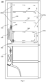
- Fig. 1 is a schematic section view of a refrigerating and freezing device 100 according to an embodiment of the present invention, showing a gas flow path that connects a refrigeration compartment 112 with a storage area 111a and disconnects the refrigeration compartment 112 from a fresh-keeping area 111b.
- the refrigerating and freezing device 100 may include a cabinet 110, a refrigeration system, a processor and a memory (the processor and the memory are not shown in Fig. 1 ).
- the cabinet 110 may include an outer container, at least one inner liner, and a thermal insulating layer arranged between the outer container and the inner liner.
- the cabinet 110 defines at least one storage compartment and at least one refrigeration compartment 112.
- Each of the inner liners defines a storage compartment and a refrigeration compartment 112, and the storage compartment and the refrigeration compartment 112 may be separated by an air duct cover plate 150.
- the storage compartments and the refrigeration compartment 112 may be independent of each other and separated by thermal insulating layers.
- the refrigeration compartment 112 may also be arranged in one inner liner together with one of the storage compartments.
- the refrigeration system may be a vapor compression refrigeration system, including a compressor, a condenser, a throttling element, an evaporator 120 and an air supply fan 130.
- the refrigeration system (e.g., the evaporator 120 and the air supply fan 130) may be at least partially arranged in the refrigeration compartment 112 to supply cold to the storage compartment.
- the memory may store a computer program which, when executed by the processor, is used to implement the control method of the present invention.
- the processor is configured to control the refrigeration system to stop supplying cold to the storage compartment, connect the refrigeration compartment 112 with the storage compartment, and control the fan 130 of the refrigeration system to operate so as to promote air in the refrigeration compartment 112 and the storage compartment to flow circularly, thereby humidifying the storage compartment.
- the air in the storage compartment is utilized to carry out air defrosting on the refrigeration compartment 112, and then the defrosted high-humidity gas is led back to the storage compartment;
- the conceptual limitation of the prior art of utilizing a heating device to generate liquid defrosted water and then carrying out humidification is broken through, and heat of the storage compartment is fully utilized to defrost the refrigeration compartment 112; and the air temperature after defrosting is more suitable, and more abundant humidity can be brought to the storage compartment, thereby reducing the production cost and energy consumption during use.
- the processor may be further configured to control the refrigeration system to supply cold to the storage compartment when a storage temperature of the storage compartment is greater than or equal to a preset start-up temperature, and then humidify the storage compartment (i.e., stopping supplying cold to the storage compartment and keeping the fan 130 operating) when the storage temperature of the storage compartment decreases to be less than or equal to a preset shutdown temperature, so as to make the temperature of the storage compartment within an allowable fluctuating range, thereby ensuring the storage quality of food in the storage compartment.
- a preset start-up temperature i.e., stopping supplying cold to the storage compartment and keeping the fan 130 operating
- the preset shutdown temperature is greater than 0°C. That is, the temperature of the storage compartment is always kept at 0°C or above to defrost the refrigeration compartment 112.
- the processor may be further configured to defrost the refrigeration compartment 112 and humidify the storage compartment (i.e., stopping supplying cold to the storage compartment and keeping the fan 130 operating) each time after the completion of refrigeration of the storage compartment (i.e., when the storage temperature of the storage compartment decreases to be less than or equal to the preset shutdown temperature), so as to avoid excessive frosting of the storage compartment, thereby increasing the effective utilization rate of cold and making the humidity of the storage compartment more stable.
- the storage compartment may be separated by shelf plates 140 and a drawer into a fresh-keeping area 111b and a storage area 111a.
- the fresh-keeping area 111b is usually configured to store fruits and vegetables.
- the processor is further configured to, when controlling the refrigeration system to supply cold to the storage compartment, connect the refrigeration compartment 112 with the storage area 111a and disconnect the refrigeration compartment 112 from the fresh-keeping area 111b, so as to avoid the humidity of the fresh-keeping area 111b from being reduced.
- the storage temperature of the storage compartment is the temperature of the storage area 111a. Whether the storage compartment needs to be supplied with cold (when the storage temperature of the storage compartment is greater than or equal to the preset start-up temperature) or whether the supply of cold to the storage compartment is completed (when the storage temperature of the storage compartment is less than or equal to the preset shutdown temperature) is judged according to the temperature of the storage area 111a.
- the fresh-keeping area 111b may be arranged below the storage area 111a, so as to supply cold to the fresh-keeping area 11 1b by means of sinking of cold air of the storage area 111a.
- Fig. 2 is a schematic section view of the refrigerating and freezing device 100 shown in Fig. 1 , showing a gas flow path that connects the refrigeration compartment 112 with the storage area 111a and the fresh-keeping area 111b.
- the processor is further configured to connect the refrigeration compartment 112 with the storage area 111a firstly after controlling the refrigeration system to stop supplying cold to the storage compartment, and connect the refrigeration compartment 112 with the storage area 111a and the fresh-keeping area 111b after a first preset time, so as to effectively humidify the fresh-keeping area 111b and keep the humidity of the storage area 111a stable.
- the processor is further configured to control the fan 130 to stop operating and disconnect the refrigeration compartment 112 from the fresh-keeping area 111b (that is, humidification of the fresh-keeping area 111b is completed) after connecting the refrigeration compartment 112 with the fresh-keeping area 111b for a second preset time, and then disconnect, after disconnecting the refrigeration compartment 112 from the fresh-keeping area 111b for a third preset time, the refrigeration compartment 112 from the storage area 111a, so as to increase the humidity of the storage area 111a.
- the fresh-keeping area 111b may be provided with a valve 160 for keeping a gas pressure of the fresh-keeping area 111b within a preset pressure threshold value to prevent the gas pressure of the fresh-keeping area 111b from being too high and causing the drawer to open automatically.
- Fig. 3 is a schematic section view of a refrigeration compartment 112 according to an embodiment of the present invention.
- the air duct cover plate 150 may form a return air inlet 152 and at least one air supply portion.
- Each air supply portion may be provided with at least one air supply port 151 and an air inlet.
- the air supply fan 130 may be arranged downstream of the evaporator 120 and includes a volute and an impeller arranged in the volute.
- the volute is configured to be rotatable and to make its air outlet to be in butt joint with the air inlet of the one or more air supply portions, so as to convey cold airflow refrigerated by the evaporator 120 to the corresponding air supply portion and blow it out from the air supply port 151 of the air supply portion.
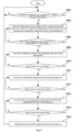
- Fig. 4 is a schematic flow chart of a control method for a refrigerating and freezing device 100 according to an embodiment of the present invention.
- the control method for the refrigerating and freezing device 100 of the present invention may include the following steps.
- a refrigeration system is controlled to stop supplying cold to a storage compartment.
- a refrigeration compartment 112 is connected with the storage compartment, and a fan 130 of the refrigeration system is controlled to operate so as to promote air in the refrigeration compartment 112 and the storage compartment to flow circularly, thereby humidifying the storage compartment.
- the air in the storage compartment is utilized to carry out air defrosting on the refrigeration compartment 112, and then the defrosted high-humidity gas is led back to the storage compartment;
- the conceptual limitation of the prior art of utilizing a heating device to generate liquid defrosted water and then carrying out humidification is broken through, and heat of the storage compartment is fully utilized to defrost the refrigeration compartment 112; and the air temperature after defrosting is more suitable, and more abundant humidity can be brought to the storage compartment, thereby reducing the production cost and energy consumption during use.
- control method of the present invention may also include the following step: controlling, when the storage temperature of the storage compartment is greater than or equal to a preset start-up temperature, the refrigeration system to supply cold to the storage compartment.
- step S402 is performed, so as to make the temperature of the storage compartment within an allowable fluctuating range, thereby ensuring the storage quality of food in the storage compartment.
- the storage temperature of the storage compartment is the temperature of the storage area 111a. Whether the storage compartment needs to be supplied with cold (when the storage temperature of the storage compartment is greater than or equal to the preset start-up temperature) or whether the supply of cold to the storage compartment is completed (when the storage temperature of the storage compartment is less than or equal to the preset shutdown temperature) is judged according to the temperature of the storage area 111a.
- the preset shutdown temperature is greater than 0°C. That is, the temperature of the storage compartment is always kept at 0°C or above to defrost the refrigeration compartment 112.
- the refrigeration compartment 112 is connected with the storage area 111a and disconnected from the fresh-keeping area 111b while the refrigeration system is controlled to supply cold to the storage compartment, so as to avoid the humidity of the fresh-keeping area 111b from being reduced.
- step S402 is performed each time the storage temperature of the storage compartment decreases to be less than or equal to the preset shutdown temperature, so as to avoid excessive frosting of the storage compartment, thereby increasing the effective utilization rate of cold and making the humidity of the storage compartment more stable.
- Step S404 further includes the following steps:
- control method of the present invention also includes the following steps:
- Fig. 5 is a schematic detailed flow chart of a control method for the refrigerating and freezing device 100 according to an embodiment of the present invention (where “Y” represents “Yes”; and “N” represents “No”).
- the control method for the refrigerating and freezing device 100 of the present invention may include the following detailed steps.
- step S502 whether a storage temperature of the storage compartment is greater than or equal to the preset start-up temperature is judged. If yes, step S504 is performed; and if not, step S502 is repeated.
- the refrigeration system is controlled to supply cold to the storage compartment, the fan 130 operates, and the refrigeration compartment 112 is connected with the storage area 111a and disconnected from the fresh-keeping area 111b .
- step S506 whether the storage temperature of the storage compartment decreases to be less than or equal to the preset shutdown temperature is judged. If yes, step S508 is performed; and if not, it returns to step S504.
- step S508 the refrigeration system is controlled to stop supplying cold to the storage compartment, the fan 130 continues to operate, and the refrigeration compartment 112 continues to be connected with the storage area 111a and disconnected from the fresh-keeping area 111b .
- step S510 whether the operation time of step S508 reaches a first preset time is judged. If yes, step S512 is performed; and if not, it returns to step S508.
- the refrigeration compartment 112 is connected with the fresh-keeping area 111b and continues to be connected with the storage area 111a.
- step S5134 whether the operation time of step S512 reaches a second preset time is judged. If yes, step S516 is performed; and if not, it returns to step S512.
- the fan 130 is controlled to stop operating, and the refrigeration compartment 112 is disconnected from the fresh-keeping area 111b and continues to be connected with the storage area 111a.
- step S516 whether the operation time of step S516 reaches a third preset time. If yes, step S520 is performed; and if not, it returns to step S516.
- step S520 the refrigeration compartment 112 is disconnected from the storage area 111a. And it returns to step S502.
Landscapes
- Engineering & Computer Science (AREA)
- Chemical & Material Sciences (AREA)
- Combustion & Propulsion (AREA)
- Physics & Mathematics (AREA)
- Mechanical Engineering (AREA)
- Thermal Sciences (AREA)
- General Engineering & Computer Science (AREA)
- Cold Air Circulating Systems And Constructional Details In Refrigerators (AREA)
- Devices That Are Associated With Refrigeration Equipment (AREA)
Description
- The present invention relates to the field of refrigerating and freezing, and particularly relates to a control method for a refrigerating and freezing device, and the refrigerating and freezing device.
- Fruits and vegetables are common food stored in refrigerators. Both low temperature and high humidity are required for keeping fruits and vegetables fresh. In the prior art, a separate fresh-keeping area is defined in a refrigerator. The fresh-keeping area is humidified by means of defrosted water produced by heating an evaporator, which not only needs to arrange an additional heating device for heating, increasing the production cost, but also increases the energy consumption for daily use, resulting in energy waste. All things considered, there is a need for a low-cost control method for a refrigerating and freezing device with a fresh-keeping area, and the refrigerating and freezing device in devising.
- For instance, prior art
JP 2017 026221 A EP 2 757 334 A1 discloses a refrigerator and a humidity control method for a chilling chamber of a refrigerator, the refrigerator comprising a body (1), a door body (2); a compressor (3); an evaporator (4); a fan (5); a first temperature sensor for detecting a temperature inside the chilling chamber (11); a second temperature sensor for detecting a temperature of the evaporator (4); a device for selecting the moisture preservation mode of the chilling chamber (61), for switching the chilling chamber between a high moisture preservation mode and a normal moisture preservation mode; and a controller (62) connected respectively to the first temperature sensor, the second temperature sensor, the compressor (3), the fan (5) and the device for selecting the moisture preservation mode of the chilling chamber (61).CN 1 248 691 A discloses cold storage chamber (2) and a vegetable chamber (3) which are connected between in the refrigerator (1). - One objective of the present invention is to overcome at least one technical defect of the prior art and to provide a control method for a refrigerating and freezing device.
- One further objective of the present invention is to reduce energy consumption.
- Another further objective of the present invention is to avoid excessive frosting of a refrigeration compartment.
- The present invention provides a control method for a refrigerating and freezing device according to claim 1.
- In the present invention, air in the storage compartment is utilized to carry out air defrosting on the refrigeration compartment, and then the defrosted high-humidity gas is led back to the storage compartment; the conceptual limitation of the prior art of utilizing a heating device to generate liquid defrosted water and then carrying out humidification is broken through, and heat of the storage compartment is fully utilized to defrost the refrigeration compartment; and the air temperature after defrosting is more suitable, and more abundant humidity can be brought to the storage compartment, thereby reducing the production cost and energy consumption during use.
- Further, in the present invention, the storage compartment is refrigerated before being humidified, so as to make the temperature of the storage compartment within an allowable fluctuating range, which ensures the storage quality of food in the storage compartment. Further, in the present invention, the storage compartment is humidified each time the storage compartment is refrigerated, which avoids excessive frosting of the storage compartment, thereby increasing the effective utilization rate of cold and making the humidity of the storage compartment more stable.
- Further, in the humidifying process of the present invention, the refrigeration compartment is connected with the storage area first and then connected with the fresh-keeping area, and after humidifying the fresh-keeping area, the refrigeration compartment continues to be connected with the storage area, thereby effectively improving the humidity of the fresh-keeping area and keeping the humidity of the storage area stable, since the inventors of the present invention inventively recognize that defrosting the refrigeration compartment with air from the storage compartment will take away water vapor from the storage compartment in an initial stage (the water vapor condenses in the refrigeration compartment).
- These and other objectives, advantages and features of the present invention will be better understood by those skilled in the art in the light of the detailed description of specific embodiments of the present invention in conjunction with the accompanying drawings below.
- Some specific embodiments of the present invention will be described below in detail in an exemplary rather than a limiting manner with reference to the accompanying drawings. Identical reference numerals in the accompanying drawings indicate identical or similar components or parts. It should be understood by those skilled in the art that these accompanying drawings are not necessarily drawn to scale. In the accompanying drawings,
-
Fig. 1 is a schematic section view of a refrigerating and freezing device according to an embodiment of the present invention, showing a gas flow path that connects a refrigeration compartment with a storage area and disconnects the refrigeration compartment from a fresh-keeping area; -
Fig. 2 is a schematic section view of the refrigerating and freezing device shown inFig. 1 , showing a gas flow path that connects the refrigeration compartment with the storage area and the fresh-keeping area; -
Fig. 3 is a schematic section view of a refrigeration compartment according to an embodiment of the present invention; -
Fig. 4 is a schematic flow chart of a control method for a refrigerating and freezing device according to an embodiment of the present invention; and -
Fig. 5 is a schematic detailed flow chart of a control method for a refrigerating and freezing device according to an embodiment of the present invention. -
Fig. 1 is a schematic section view of a refrigerating and freezingdevice 100 according to an embodiment of the present invention, showing a gas flow path that connects arefrigeration compartment 112 with astorage area 111a and disconnects therefrigeration compartment 112 from a fresh-keeping area 111b. Referring toFig. 1 , the refrigerating and freezingdevice 100 may include acabinet 110, a refrigeration system, a processor and a memory (the processor and the memory are not shown inFig. 1 ). - The
cabinet 110 may include an outer container, at least one inner liner, and a thermal insulating layer arranged between the outer container and the inner liner. Thecabinet 110 defines at least one storage compartment and at least onerefrigeration compartment 112. In the illustrated embodiment, there are two inner liners, two storage compartments and tworefrigeration compartments 112. Each of the inner liners defines a storage compartment and arefrigeration compartment 112, and the storage compartment and therefrigeration compartment 112 may be separated by an airduct cover plate 150. - In some other embodiments, there may be a plurality of storage compartments, and there may be one
refrigeration compartment 112. The storage compartments and therefrigeration compartment 112 may be independent of each other and separated by thermal insulating layers. Therefrigeration compartment 112 may also be arranged in one inner liner together with one of the storage compartments. - The refrigeration system may be a vapor compression refrigeration system, including a compressor, a condenser, a throttling element, an
evaporator 120 and anair supply fan 130. The refrigeration system (e.g., theevaporator 120 and the air supply fan 130) may be at least partially arranged in therefrigeration compartment 112 to supply cold to the storage compartment. - The memory may store a computer program which, when executed by the processor, is used to implement the control method of the present invention.
- The processor is configured to control the refrigeration system to stop supplying cold to the storage compartment, connect the
refrigeration compartment 112 with the storage compartment, and control thefan 130 of the refrigeration system to operate so as to promote air in therefrigeration compartment 112 and the storage compartment to flow circularly, thereby humidifying the storage compartment. - As for the refrigerating and freezing
device 100 of the present invention, the air in the storage compartment is utilized to carry out air defrosting on therefrigeration compartment 112, and then the defrosted high-humidity gas is led back to the storage compartment; the conceptual limitation of the prior art of utilizing a heating device to generate liquid defrosted water and then carrying out humidification is broken through, and heat of the storage compartment is fully utilized to defrost therefrigeration compartment 112; and the air temperature after defrosting is more suitable, and more abundant humidity can be brought to the storage compartment, thereby reducing the production cost and energy consumption during use. - In some embodiments, before the step of controlling the refrigeration system to stop supplying cold to the storage compartment, the processor may be further configured to control the refrigeration system to supply cold to the storage compartment when a storage temperature of the storage compartment is greater than or equal to a preset start-up temperature, and then humidify the storage compartment (i.e., stopping supplying cold to the storage compartment and keeping the
fan 130 operating) when the storage temperature of the storage compartment decreases to be less than or equal to a preset shutdown temperature, so as to make the temperature of the storage compartment within an allowable fluctuating range, thereby ensuring the storage quality of food in the storage compartment. - The preset shutdown temperature is greater than 0°C. That is, the temperature of the storage compartment is always kept at 0°C or above to defrost the
refrigeration compartment 112. - In some further embodiments, the processor may be further configured to defrost the
refrigeration compartment 112 and humidify the storage compartment (i.e., stopping supplying cold to the storage compartment and keeping thefan 130 operating) each time after the completion of refrigeration of the storage compartment (i.e., when the storage temperature of the storage compartment decreases to be less than or equal to the preset shutdown temperature), so as to avoid excessive frosting of the storage compartment, thereby increasing the effective utilization rate of cold and making the humidity of the storage compartment more stable. - In some embodiments, the storage compartment may be separated by
shelf plates 140 and a drawer into a fresh-keeping area 111b and astorage area 111a. The fresh-keepingarea 111b is usually configured to store fruits and vegetables. - The processor is further configured to, when controlling the refrigeration system to supply cold to the storage compartment, connect the
refrigeration compartment 112 with thestorage area 111a and disconnect therefrigeration compartment 112 from the fresh-keepingarea 111b, so as to avoid the humidity of the fresh-keepingarea 111b from being reduced. In this embodiment, the storage temperature of the storage compartment is the temperature of thestorage area 111a. Whether the storage compartment needs to be supplied with cold (when the storage temperature of the storage compartment is greater than or equal to the preset start-up temperature) or whether the supply of cold to the storage compartment is completed (when the storage temperature of the storage compartment is less than or equal to the preset shutdown temperature) is judged according to the temperature of thestorage area 111a. - The fresh-
keeping area 111b may be arranged below thestorage area 111a, so as to supply cold to the fresh-keeping area 11 1b by means of sinking of cold air of thestorage area 111a. -
Fig. 2 is a schematic section view of the refrigerating and freezingdevice 100 shown inFig. 1 , showing a gas flow path that connects therefrigeration compartment 112 with thestorage area 111a and the fresh-keeping area 111b. Referring toFig. 1 andFig. 2 , the processor is further configured to connect therefrigeration compartment 112 with thestorage area 111a firstly after controlling the refrigeration system to stop supplying cold to the storage compartment, and connect therefrigeration compartment 112 with thestorage area 111a and the fresh-keepingarea 111b after a first preset time, so as to effectively humidify the fresh-keepingarea 111b and keep the humidity of thestorage area 111a stable. - The processor is further configured to control the
fan 130 to stop operating and disconnect therefrigeration compartment 112 from the fresh-keepingarea 111b (that is, humidification of the fresh-keepingarea 111b is completed) after connecting therefrigeration compartment 112 with the fresh-keepingarea 111b for a second preset time, and then disconnect, after disconnecting therefrigeration compartment 112 from the fresh-keepingarea 111b for a third preset time, therefrigeration compartment 112 from thestorage area 111a, so as to increase the humidity of thestorage area 111a. - The fresh-keeping
area 111b may be provided with avalve 160 for keeping a gas pressure of the fresh-keepingarea 111b within a preset pressure threshold value to prevent the gas pressure of the fresh-keepingarea 111b from being too high and causing the drawer to open automatically. -
Fig. 3 is a schematic section view of arefrigeration compartment 112 according to an embodiment of the present invention. Referring toFig. 1 to Fig. 3 , the airduct cover plate 150 may form areturn air inlet 152 and at least one air supply portion. Each air supply portion may be provided with at least oneair supply port 151 and an air inlet. - The
air supply fan 130 may be arranged downstream of theevaporator 120 and includes a volute and an impeller arranged in the volute. The volute is configured to be rotatable and to make its air outlet to be in butt joint with the air inlet of the one or more air supply portions, so as to convey cold airflow refrigerated by theevaporator 120 to the corresponding air supply portion and blow it out from theair supply port 151 of the air supply portion. -
Fig. 4 is a schematic flow chart of a control method for a refrigerating and freezingdevice 100 according to an embodiment of the present invention. Referring toFig. 4 , the control method for the refrigerating and freezingdevice 100 of the present invention may include the following steps. - At step S402, a refrigeration system is controlled to stop supplying cold to a storage compartment.
- At step S404, a
refrigeration compartment 112 is connected with the storage compartment, and afan 130 of the refrigeration system is controlled to operate so as to promote air in therefrigeration compartment 112 and the storage compartment to flow circularly, thereby humidifying the storage compartment. - As for the control method of the present invention, the air in the storage compartment is utilized to carry out air defrosting on the
refrigeration compartment 112, and then the defrosted high-humidity gas is led back to the storage compartment; the conceptual limitation of the prior art of utilizing a heating device to generate liquid defrosted water and then carrying out humidification is broken through, and heat of the storage compartment is fully utilized to defrost therefrigeration compartment 112; and the air temperature after defrosting is more suitable, and more abundant humidity can be brought to the storage compartment, thereby reducing the production cost and energy consumption during use. - In some embodiments, before step S402, the control method of the present invention may also include the following step:
controlling, when the storage temperature of the storage compartment is greater than or equal to a preset start-up temperature, the refrigeration system to supply cold to the storage compartment. - Further, when the storage temperature of the storage compartment decreases to be less than or equal to a preset shutdown temperature, step S402 is performed, so as to make the temperature of the storage compartment within an allowable fluctuating range, thereby ensuring the storage quality of food in the storage compartment.
- In the present invention, the storage temperature of the storage compartment is the temperature of the
storage area 111a. Whether the storage compartment needs to be supplied with cold (when the storage temperature of the storage compartment is greater than or equal to the preset start-up temperature) or whether the supply of cold to the storage compartment is completed (when the storage temperature of the storage compartment is less than or equal to the preset shutdown temperature) is judged according to the temperature of thestorage area 111a. - The preset shutdown temperature is greater than 0°C. That is, the temperature of the storage compartment is always kept at 0°C or above to defrost the
refrigeration compartment 112. - In some further embodiments, the
refrigeration compartment 112 is connected with thestorage area 111a and disconnected from the fresh-keepingarea 111b while the refrigeration system is controlled to supply cold to the storage compartment, so as to avoid the humidity of the fresh-keepingarea 111b from being reduced. - In some further embodiments, step S402 is performed each time the storage temperature of the storage compartment decreases to be less than or equal to the preset shutdown temperature, so as to avoid excessive frosting of the storage compartment, thereby increasing the effective utilization rate of cold and making the humidity of the storage compartment more stable.
- Step S404 further includes the following steps:
- connecting the
refrigeration compartment 112 with thestorage area 111a; and - connecting the
refrigeration compartment 112 with thestorage area 111a and the fresh-keepingarea 111b to humidify the fresh-keepingarea 111b after a first preset time, so as to effectively humidify the fresh-keepingarea 111b and keep the humidity of thestorage area 111a stable. - The control method of the present invention also includes the following steps:
- controlling the
fan 130 to stop operating and disconnecting therefrigeration compartment 112 from the fresh-keepingarea 111b after performing the step of connecting therefrigeration compartment 112 with thestorage area 111a and the fresh-keepingarea 111b for a second preset time; and - disconnecting, after a third preset time, the
refrigeration compartment 112 from thestorage area 111a, so as to increase the humidity of thestorage area 111a. -
Fig. 5 is a schematic detailed flow chart of a control method for the refrigerating and freezingdevice 100 according to an embodiment of the present invention (where "Y" represents "Yes"; and "N" represents "No"). Referring toFig. 5 , the control method for the refrigerating and freezingdevice 100 of the present invention may include the following detailed steps. - At step S502, whether a storage temperature of the storage compartment is greater than or equal to the preset start-up temperature is judged. If yes, step S504 is performed; and if not, step S502 is repeated.
- At step S504, the refrigeration system is controlled to supply cold to the storage compartment, the
fan 130 operates, and therefrigeration compartment 112 is connected with thestorage area 111a and disconnected from the fresh-keepingarea 111b . - At step S506, whether the storage temperature of the storage compartment decreases to be less than or equal to the preset shutdown temperature is judged. If yes, step S508 is performed; and if not, it returns to step S504.
- At step S508, the refrigeration system is controlled to stop supplying cold to the storage compartment, the
fan 130 continues to operate, and therefrigeration compartment 112 continues to be connected with thestorage area 111a and disconnected from the fresh-keepingarea 111b . - At step S510, whether the operation time of step S508 reaches a first preset time is judged. If yes, step S512 is performed; and if not, it returns to step S508.
- At step S512, the
refrigeration compartment 112 is connected with the fresh-keepingarea 111b and continues to be connected with thestorage area 111a. - At step S514, whether the operation time of step S512 reaches a second preset time is judged. If yes, step S516 is performed; and if not, it returns to step S512.
- At S516, the
fan 130 is controlled to stop operating, and therefrigeration compartment 112 is disconnected from the fresh-keepingarea 111b and continues to be connected with thestorage area 111a. - At step S518, whether the operation time of step S516 reaches a third preset time. If yes, step S520 is performed; and if not, it returns to step S516.
- At step S520, the
refrigeration compartment 112 is disconnected from thestorage area 111a. And it returns to step S502.
Claims (5)
- A control method for a refrigerating and freezing device (100), the refrigerating and freezing device (100) comprising a storage compartment, a refrigeration compartment (112), and a refrigeration system at least partially arranged in the refrigeration compartment (112), wherein the control method comprises:controlling the refrigeration system to stop supplying cold to the storage compartment; andconnecting the refrigeration compartment (112) with the storage compartment, and controlling a fan of the refrigeration system to operate so as to promote air in the refrigeration compartment (112) and the storage compartment to flow circularly, the storage compartment being separated into a fresh-keeping area (111b) and a storage area (111a),characterized in that the step of connecting the refrigeration compartment (112) with the storage compartment comprises:connecting the refrigeration compartment (112) with the storage area (111a); andconnecting, after a first preset time, the refrigeration compartment (112) with the storage area (111a) and the fresh-keeping area (111b) to humidify the fresh-keeping area (111b), further comprising:controlling the fan to stop operating and disconnecting the refrigeration compartment (112) from the fresh-keeping area (111b) after performing the step of connecting the refrigeration compartment (112) with the storage area (1 11a) and the fresh-keeping area (111b) for a second preset time; anddisconnecting, after a third preset time, the refrigeration compartment (112) from the storage area (111a).
- The control method according to claim 1, before the step of controlling the refrigeration system to stop supplying cold to the storage compartment, further comprising:controlling, when a storage temperature of the storage compartment is greater than or equal to a preset start-up temperature, the refrigeration system to supply cold to the storage compartment; andperforming, when the storage temperature of the storage compartment decreases to be less than or equal to a preset shutdown temperature, the step of controlling the refrigeration system to stop supplying cold to the storage compartment.
- The control method according to claim 2, whereinthe storage temperature of the storage compartment is the temperature of the storage area (111a); and/orthe storage temperature of the storage compartment is greater than 0°C.
- The control method according to claim 2 or 3, wherein while performing the step of controlling the refrigeration system to supply cold to the storage compartment, the control method further comprises:
connecting the refrigeration compartment (112) with the storage area (111a), and disconnecting the refrigeration compartment (112) from the fresh-keeping area (111b). - The control method according to any one of claims 2 to 4, wherein
the step of controlling the refrigeration system to stop supplying cold to the storage compartment is performed each time the storage temperature of the storage compartment decreases to be less than or equal to the preset shutdown temperature.
Applications Claiming Priority (2)
| Application Number | Priority Date | Filing Date | Title |
|---|---|---|---|
| CN202010653066.6A CN113915845A (en) | 2020-07-08 | 2020-07-08 | Control method for refrigerating and freezing device and refrigerating and freezing device |
| PCT/CN2021/103182 WO2021219148A1 (en) | 2020-07-08 | 2021-06-29 | Refrigerating and freezing apparatus control method, and refrigerating and freezing apparatus |
Publications (3)
| Publication Number | Publication Date |
|---|---|
| EP4155637A1 EP4155637A1 (en) | 2023-03-29 |
| EP4155637A4 EP4155637A4 (en) | 2024-02-28 |
| EP4155637B1 true EP4155637B1 (en) | 2024-12-04 |
Family
ID=78374085
Family Applications (1)
| Application Number | Title | Priority Date | Filing Date |
|---|---|---|---|
| EP21795308.2A Active EP4155637B1 (en) | 2020-07-08 | 2021-06-29 | Refrigerating and freezing apparatus control method |
Country Status (6)
| Country | Link |
|---|---|
| US (1) | US12366402B2 (en) |
| EP (1) | EP4155637B1 (en) |
| JP (1) | JP2023532588A (en) |
| CN (1) | CN113915845A (en) |
| AU (1) | AU2021262372B2 (en) |
| WO (1) | WO2021219148A1 (en) |
Families Citing this family (1)
| Publication number | Priority date | Publication date | Assignee | Title |
|---|---|---|---|---|
| CN116717946A (en) * | 2022-02-28 | 2023-09-08 | 青岛海尔电冰箱有限公司 | Refrigeration and freezing device and control method thereof |
Family Cites Families (18)
| Publication number | Priority date | Publication date | Assignee | Title |
|---|---|---|---|---|
| JP2763622B2 (en) | 1989-10-25 | 1998-06-11 | 松下冷機株式会社 | Refrigerator with thawing room |
| JPH10311649A (en) * | 1997-05-15 | 1998-11-24 | Fuji Electric Co Ltd | Food freezer and its operation control method |
| JP3559715B2 (en) * | 1998-09-18 | 2004-09-02 | 株式会社東芝 | refrigerator |
| JP4076804B2 (en) | 2002-07-08 | 2008-04-16 | 株式会社東芝 | refrigerator |
| US7284390B2 (en) * | 2005-05-18 | 2007-10-23 | Whirlpool Corporation | Refrigerator with intermediate temperature icemaking compartment |
| CN101586898A (en) * | 2008-05-20 | 2009-11-25 | 海信(北京)电器有限公司 | Air-cooled refrigerator and defrosting method of same |
| DK2757334T3 (en) * | 2011-09-14 | 2019-04-01 | Hefei Midea Refrigerator Co | Refrigerator and method for controlling the humidity in a refrigerator of a refrigerator |
| KR101923475B1 (en) * | 2012-06-26 | 2019-02-22 | 엘지전자 주식회사 | A device protecting the over-degree of a vaccum for a vegetables container of a refrigerator and a vegetables container having it |
| KR101932047B1 (en) | 2012-07-17 | 2019-03-20 | 엘지전자 주식회사 | A refrigerator vegetable room for dew condensation reduction and refrigerator having the same, dew condensation reduction method for vegetable room of refrigerator |
| CN106152670B (en) * | 2015-04-03 | 2024-07-12 | 青岛海尔智能技术研发有限公司 | Refrigeration and freezing equipment |
| JP2017026221A (en) * | 2015-07-22 | 2017-02-02 | 東芝ライフスタイル株式会社 | refrigerator |
| CN206001774U (en) * | 2016-08-31 | 2017-03-08 | 合肥美菱股份有限公司 | A kind of refrigerator with moisture-keeping functions |
| CN106802052A (en) * | 2017-02-15 | 2017-06-06 | 合肥华凌股份有限公司 | Fridge freshness retaining system and its control method and refrigerator |
| CN106766537A (en) * | 2017-02-28 | 2017-05-31 | 海信(山东)冰箱有限公司 | A kind of three compartment refrigerators and its control method of defrost and moisturizing |
| CN106969594A (en) * | 2017-05-03 | 2017-07-21 | 合肥美的电冰箱有限公司 | Fresh-keeping control method, refrigeration system and refrigerator |
| KR102418005B1 (en) * | 2017-08-28 | 2022-07-07 | 삼성전자주식회사 | Refrigerator and controlling method thereof |
| CN210772951U (en) * | 2019-08-29 | 2020-06-16 | 海信(山东)冰箱有限公司 | Refrigerator with sealed drawer |
| CN111059841B (en) * | 2019-12-27 | 2023-08-18 | 青岛海尔智能技术研发有限公司 | Control method for refrigerating and freezing device and refrigerating and freezing device |
-
2020
- 2020-07-08 CN CN202010653066.6A patent/CN113915845A/en active Pending
-
2021
- 2021-06-29 US US18/004,497 patent/US12366402B2/en active Active
- 2021-06-29 WO PCT/CN2021/103182 patent/WO2021219148A1/en not_active Ceased
- 2021-06-29 EP EP21795308.2A patent/EP4155637B1/en active Active
- 2021-06-29 AU AU2021262372A patent/AU2021262372B2/en active Active
- 2021-06-29 JP JP2023500359A patent/JP2023532588A/en active Pending
Also Published As
| Publication number | Publication date |
|---|---|
| US20230251013A1 (en) | 2023-08-10 |
| EP4155637A1 (en) | 2023-03-29 |
| CN113915845A (en) | 2022-01-11 |
| EP4155637A4 (en) | 2024-02-28 |
| AU2021262372B2 (en) | 2024-03-14 |
| KR20230023752A (en) | 2023-02-17 |
| US12366402B2 (en) | 2025-07-22 |
| AU2021262372A1 (en) | 2023-02-16 |
| JP2023532588A (en) | 2023-07-28 |
| WO2021219148A1 (en) | 2021-11-04 |
Similar Documents
| Publication | Publication Date | Title |
|---|---|---|
| US6658879B2 (en) | Direct cooling type refrigerator | |
| CN103851874B (en) | There is the refrigerator low temperature compensating method of temperature-changing chamber | |
| JP2002147917A (en) | Refrigerating equipment and refrigerator provided with refrigerating equipment | |
| CN106482441A (en) | Refrigeration plant method of work and refrigeration plant | |
| CN104329872A (en) | Refrigerator evaporator defrosting method | |
| US10132548B2 (en) | Secondary cooling path in refrigerator | |
| CN112393492A (en) | Humidity control method for refrigerating chamber and refrigerator | |
| JP7516568B2 (en) | Method for controlling defrosting of a refrigerator | |
| CN106766508A (en) | Self-loopa moisture preservation refrigerator and its moisturizing control method | |
| AU2021262372B2 (en) | Refrigerating and freezing apparatus control method, and refrigerating and freezing apparatus | |
| JP2000230767A (en) | Refrigerator | |
| US20230332818A1 (en) | Method for controlling temperature of refrigerator, and refrigerator | |
| US20070137226A1 (en) | Refrigerator and method for controlling the refrigerator | |
| WO2023029521A1 (en) | Refrigerating and freezing apparatus and control method therefor | |
| CN115950125A (en) | Defrosting control method, refrigerating system and refrigerating equipment | |
| JP2001133112A (en) | Refrigerator | |
| CN115978869B (en) | Refrigerator with independent ice making evaporator | |
| KR102964936B1 (en) | Control method for refrigeration and freezing devices and refrigeration and freezing devices | |
| CN109883104A (en) | Refrigerator and its control method | |
| CN115978870B (en) | refrigerator | |
| JP2005024203A (en) | refrigerator | |
| CN104094071B (en) | There is the refrigerating appliance of two storage chambers | |
| CN119737722A (en) | Car refrigerator temperature control method, car refrigerator, electronic device and storage medium | |
| CN120444817A (en) | Refrigeration appliances | |
| CN120444816A (en) | Refrigerating appliance |
Legal Events
| Date | Code | Title | Description |
|---|---|---|---|
| STAA | Information on the status of an ep patent application or granted ep patent |
Free format text: STATUS: THE INTERNATIONAL PUBLICATION HAS BEEN MADE |
|
| PUAI | Public reference made under article 153(3) epc to a published international application that has entered the european phase |
Free format text: ORIGINAL CODE: 0009012 |
|
| STAA | Information on the status of an ep patent application or granted ep patent |
Free format text: STATUS: REQUEST FOR EXAMINATION WAS MADE |
|
| 17P | Request for examination filed |
Effective date: 20221223 |
|
| AK | Designated contracting states |
Kind code of ref document: A1 Designated state(s): AL AT BE BG CH CY CZ DE DK EE ES FI FR GB GR HR HU IE IS IT LI LT LU LV MC MK MT NL NO PL PT RO RS SE SI SK SM TR |
|
| DAV | Request for validation of the european patent (deleted) | ||
| DAX | Request for extension of the european patent (deleted) | ||
| REG | Reference to a national code |
Ref country code: DE Ref legal event code: R079 Free format text: PREVIOUS MAIN CLASS: F25D0029000000 Ipc: F25D0017040000 Ref document number: 602021022977 Country of ref document: DE |
|
| RIC1 | Information provided on ipc code assigned before grant |
Ipc: F25D 21/12 20060101ALI20231023BHEP Ipc: F25D 17/04 20060101AFI20231023BHEP |
|
| STAA | Information on the status of an ep patent application or granted ep patent |
Free format text: STATUS: EXAMINATION IS IN PROGRESS |
|
| A4 | Supplementary search report drawn up and despatched |
Effective date: 20240129 |
|
| RIC1 | Information provided on ipc code assigned before grant |
Ipc: F25D 21/12 20060101ALI20240123BHEP Ipc: F25D 17/04 20060101AFI20240123BHEP |
|
| 17Q | First examination report despatched |
Effective date: 20240212 |
|
| GRAP | Despatch of communication of intention to grant a patent |
Free format text: ORIGINAL CODE: EPIDOSNIGR1 |
|
| STAA | Information on the status of an ep patent application or granted ep patent |
Free format text: STATUS: GRANT OF PATENT IS INTENDED |
|
| RIC1 | Information provided on ipc code assigned before grant |
Ipc: F25D 21/12 20060101ALI20240710BHEP Ipc: F25D 17/04 20060101AFI20240710BHEP |
|
| INTG | Intention to grant announced |
Effective date: 20240719 |
|
| GRAS | Grant fee paid |
Free format text: ORIGINAL CODE: EPIDOSNIGR3 |
|
| GRAA | (expected) grant |
Free format text: ORIGINAL CODE: 0009210 |
|
| STAA | Information on the status of an ep patent application or granted ep patent |
Free format text: STATUS: THE PATENT HAS BEEN GRANTED |
|
| AK | Designated contracting states |
Kind code of ref document: B1 Designated state(s): AL AT BE BG CH CY CZ DE DK EE ES FI FR GB GR HR HU IE IS IT LI LT LU LV MC MK MT NL NO PL PT RO RS SE SI SK SM TR |
|
| REG | Reference to a national code |
Ref country code: CH Ref legal event code: EP |
|
| REG | Reference to a national code |
Ref country code: DE Ref legal event code: R096 Ref document number: 602021022977 Country of ref document: DE |
|
| REG | Reference to a national code |
Ref country code: IE Ref legal event code: FG4D |
|
| REG | Reference to a national code |
Ref country code: LT Ref legal event code: MG9D |
|
| REG | Reference to a national code |
Ref country code: NL Ref legal event code: MP Effective date: 20241204 |
|
| PG25 | Lapsed in a contracting state [announced via postgrant information from national office to epo] |
Ref country code: HR Free format text: LAPSE BECAUSE OF FAILURE TO SUBMIT A TRANSLATION OF THE DESCRIPTION OR TO PAY THE FEE WITHIN THE PRESCRIBED TIME-LIMIT Effective date: 20241204 |
|
| PG25 | Lapsed in a contracting state [announced via postgrant information from national office to epo] |
Ref country code: FI Free format text: LAPSE BECAUSE OF FAILURE TO SUBMIT A TRANSLATION OF THE DESCRIPTION OR TO PAY THE FEE WITHIN THE PRESCRIBED TIME-LIMIT Effective date: 20241204 |
|
| PG25 | Lapsed in a contracting state [announced via postgrant information from national office to epo] |
Ref country code: BG Free format text: LAPSE BECAUSE OF FAILURE TO SUBMIT A TRANSLATION OF THE DESCRIPTION OR TO PAY THE FEE WITHIN THE PRESCRIBED TIME-LIMIT Effective date: 20241204 |
|
| PG25 | Lapsed in a contracting state [announced via postgrant information from national office to epo] |
Ref country code: ES Free format text: LAPSE BECAUSE OF FAILURE TO SUBMIT A TRANSLATION OF THE DESCRIPTION OR TO PAY THE FEE WITHIN THE PRESCRIBED TIME-LIMIT Effective date: 20241204 |
|
| PG25 | Lapsed in a contracting state [announced via postgrant information from national office to epo] |
Ref country code: NO Free format text: LAPSE BECAUSE OF FAILURE TO SUBMIT A TRANSLATION OF THE DESCRIPTION OR TO PAY THE FEE WITHIN THE PRESCRIBED TIME-LIMIT Effective date: 20250304 |
|
| PG25 | Lapsed in a contracting state [announced via postgrant information from national office to epo] |
Ref country code: GR Free format text: LAPSE BECAUSE OF FAILURE TO SUBMIT A TRANSLATION OF THE DESCRIPTION OR TO PAY THE FEE WITHIN THE PRESCRIBED TIME-LIMIT Effective date: 20250305 Ref country code: LV Free format text: LAPSE BECAUSE OF FAILURE TO SUBMIT A TRANSLATION OF THE DESCRIPTION OR TO PAY THE FEE WITHIN THE PRESCRIBED TIME-LIMIT Effective date: 20241204 |
|
| PG25 | Lapsed in a contracting state [announced via postgrant information from national office to epo] |
Ref country code: RS Free format text: LAPSE BECAUSE OF FAILURE TO SUBMIT A TRANSLATION OF THE DESCRIPTION OR TO PAY THE FEE WITHIN THE PRESCRIBED TIME-LIMIT Effective date: 20250304 |
|
| PG25 | Lapsed in a contracting state [announced via postgrant information from national office to epo] |
Ref country code: NL Free format text: LAPSE BECAUSE OF FAILURE TO SUBMIT A TRANSLATION OF THE DESCRIPTION OR TO PAY THE FEE WITHIN THE PRESCRIBED TIME-LIMIT Effective date: 20241204 |
|
| REG | Reference to a national code |
Ref country code: AT Ref legal event code: MK05 Ref document number: 1748574 Country of ref document: AT Kind code of ref document: T Effective date: 20241204 |
|
| PG25 | Lapsed in a contracting state [announced via postgrant information from national office to epo] |
Ref country code: SM Free format text: LAPSE BECAUSE OF FAILURE TO SUBMIT A TRANSLATION OF THE DESCRIPTION OR TO PAY THE FEE WITHIN THE PRESCRIBED TIME-LIMIT Effective date: 20241204 |
|
| PG25 | Lapsed in a contracting state [announced via postgrant information from national office to epo] |
Ref country code: PL Free format text: LAPSE BECAUSE OF FAILURE TO SUBMIT A TRANSLATION OF THE DESCRIPTION OR TO PAY THE FEE WITHIN THE PRESCRIBED TIME-LIMIT Effective date: 20241204 |
|
| PGFP | Annual fee paid to national office [announced via postgrant information from national office to epo] |
Ref country code: DE Payment date: 20250617 Year of fee payment: 5 |
|
| PGFP | Annual fee paid to national office [announced via postgrant information from national office to epo] |
Ref country code: GB Payment date: 20250625 Year of fee payment: 5 |
|
| PG25 | Lapsed in a contracting state [announced via postgrant information from national office to epo] |
Ref country code: IS Free format text: LAPSE BECAUSE OF FAILURE TO SUBMIT A TRANSLATION OF THE DESCRIPTION OR TO PAY THE FEE WITHIN THE PRESCRIBED TIME-LIMIT Effective date: 20250404 |
|
| PG25 | Lapsed in a contracting state [announced via postgrant information from national office to epo] |
Ref country code: PT Free format text: LAPSE BECAUSE OF FAILURE TO SUBMIT A TRANSLATION OF THE DESCRIPTION OR TO PAY THE FEE WITHIN THE PRESCRIBED TIME-LIMIT Effective date: 20250404 |
|
| PG25 | Lapsed in a contracting state [announced via postgrant information from national office to epo] |
Ref country code: EE Free format text: LAPSE BECAUSE OF FAILURE TO SUBMIT A TRANSLATION OF THE DESCRIPTION OR TO PAY THE FEE WITHIN THE PRESCRIBED TIME-LIMIT Effective date: 20241204 |
|
| PGFP | Annual fee paid to national office [announced via postgrant information from national office to epo] |
Ref country code: FR Payment date: 20250630 Year of fee payment: 5 |
|
| PG25 | Lapsed in a contracting state [announced via postgrant information from national office to epo] |
Ref country code: AT Free format text: LAPSE BECAUSE OF FAILURE TO SUBMIT A TRANSLATION OF THE DESCRIPTION OR TO PAY THE FEE WITHIN THE PRESCRIBED TIME-LIMIT Effective date: 20241204 Ref country code: RO Free format text: LAPSE BECAUSE OF FAILURE TO SUBMIT A TRANSLATION OF THE DESCRIPTION OR TO PAY THE FEE WITHIN THE PRESCRIBED TIME-LIMIT Effective date: 20241204 |
|
| PG25 | Lapsed in a contracting state [announced via postgrant information from national office to epo] |
Ref country code: SK Free format text: LAPSE BECAUSE OF FAILURE TO SUBMIT A TRANSLATION OF THE DESCRIPTION OR TO PAY THE FEE WITHIN THE PRESCRIBED TIME-LIMIT Effective date: 20241204 |
|
| PG25 | Lapsed in a contracting state [announced via postgrant information from national office to epo] |
Ref country code: CZ Free format text: LAPSE BECAUSE OF FAILURE TO SUBMIT A TRANSLATION OF THE DESCRIPTION OR TO PAY THE FEE WITHIN THE PRESCRIBED TIME-LIMIT Effective date: 20241204 |
|
| PG25 | Lapsed in a contracting state [announced via postgrant information from national office to epo] |
Ref country code: IT Free format text: LAPSE BECAUSE OF FAILURE TO SUBMIT A TRANSLATION OF THE DESCRIPTION OR TO PAY THE FEE WITHIN THE PRESCRIBED TIME-LIMIT Effective date: 20241204 |
|
| REG | Reference to a national code |
Ref country code: DE Ref legal event code: R097 Ref document number: 602021022977 Country of ref document: DE |
|
| PG25 | Lapsed in a contracting state [announced via postgrant information from national office to epo] |
Ref country code: SE Free format text: LAPSE BECAUSE OF FAILURE TO SUBMIT A TRANSLATION OF THE DESCRIPTION OR TO PAY THE FEE WITHIN THE PRESCRIBED TIME-LIMIT Effective date: 20241204 |
|
| PG25 | Lapsed in a contracting state [announced via postgrant information from national office to epo] |
Ref country code: DK Free format text: LAPSE BECAUSE OF FAILURE TO SUBMIT A TRANSLATION OF THE DESCRIPTION OR TO PAY THE FEE WITHIN THE PRESCRIBED TIME-LIMIT Effective date: 20241204 |
|
| PLBE | No opposition filed within time limit |
Free format text: ORIGINAL CODE: 0009261 |
|
| STAA | Information on the status of an ep patent application or granted ep patent |
Free format text: STATUS: NO OPPOSITION FILED WITHIN TIME LIMIT |
|
| REG | Reference to a national code |
Ref country code: CH Ref legal event code: L10 Free format text: ST27 STATUS EVENT CODE: U-0-0-L10-L00 (AS PROVIDED BY THE NATIONAL OFFICE) Effective date: 20251015 |
|
| 26N | No opposition filed |
Effective date: 20250905 |
|
| REG | Reference to a national code |
Ref country code: CH Ref legal event code: H13 Free format text: ST27 STATUS EVENT CODE: U-0-0-H10-H13 (AS PROVIDED BY THE NATIONAL OFFICE) Effective date: 20260127 |
|
| PG25 | Lapsed in a contracting state [announced via postgrant information from national office to epo] |
Ref country code: MC Free format text: LAPSE BECAUSE OF FAILURE TO SUBMIT A TRANSLATION OF THE DESCRIPTION OR TO PAY THE FEE WITHIN THE PRESCRIBED TIME-LIMIT Effective date: 20241204 |
|
| PG25 | Lapsed in a contracting state [announced via postgrant information from national office to epo] |
Ref country code: LU Free format text: LAPSE BECAUSE OF NON-PAYMENT OF DUE FEES Effective date: 20250629 |
|
| REG | Reference to a national code |
Ref country code: BE Ref legal event code: MM Effective date: 20250630 |
|
| PG25 | Lapsed in a contracting state [announced via postgrant information from national office to epo] |
Ref country code: IE Free format text: LAPSE BECAUSE OF NON-PAYMENT OF DUE FEES Effective date: 20250629 |
|
| PG25 | Lapsed in a contracting state [announced via postgrant information from national office to epo] |
Ref country code: BE Free format text: LAPSE BECAUSE OF NON-PAYMENT OF DUE FEES Effective date: 20250630 |
|
| PG25 | Lapsed in a contracting state [announced via postgrant information from national office to epo] |
Ref country code: CH Free format text: LAPSE BECAUSE OF NON-PAYMENT OF DUE FEES Effective date: 20250630 |