EP4155628A1 - Heat pump having a capillary, home appliance containing the heat pump and a process for manufacturing a heat pump - Google Patents
Heat pump having a capillary, home appliance containing the heat pump and a process for manufacturing a heat pump Download PDFInfo
- Publication number
- EP4155628A1 EP4155628A1 EP22196206.1A EP22196206A EP4155628A1 EP 4155628 A1 EP4155628 A1 EP 4155628A1 EP 22196206 A EP22196206 A EP 22196206A EP 4155628 A1 EP4155628 A1 EP 4155628A1
- Authority
- EP
- European Patent Office
- Prior art keywords
- capillary
- heat pump
- evaporator
- refrigerant
- pump according
- Prior art date
- Legal status (The legal status is an assumption and is not a legal conclusion. Google has not performed a legal analysis and makes no representation as to the accuracy of the status listed.)
- Pending
Links
- 238000000034 method Methods 0.000 title claims description 12
- 238000004519 manufacturing process Methods 0.000 title claims description 9
- 239000003507 refrigerant Substances 0.000 claims abstract description 42
- 238000005520 cutting process Methods 0.000 claims description 19
- 238000004080 punching Methods 0.000 claims description 5
- 238000009966 trimming Methods 0.000 claims description 5
- XLYOFNOQVPJJNP-UHFFFAOYSA-N water Substances O XLYOFNOQVPJJNP-UHFFFAOYSA-N 0.000 claims description 5
- RYGMFSIKBFXOCR-UHFFFAOYSA-N Copper Chemical compound [Cu] RYGMFSIKBFXOCR-UHFFFAOYSA-N 0.000 claims description 3
- 229910052802 copper Inorganic materials 0.000 claims description 3
- 239000010949 copper Substances 0.000 claims description 3
- 238000001035 drying Methods 0.000 description 4
- 238000005219 brazing Methods 0.000 description 3
- 239000000463 material Substances 0.000 description 3
- 238000005476 soldering Methods 0.000 description 3
- ATUOYWHBWRKTHZ-UHFFFAOYSA-N Propane Chemical compound CCC ATUOYWHBWRKTHZ-UHFFFAOYSA-N 0.000 description 2
- 230000007704 transition Effects 0.000 description 2
- 238000005406 washing Methods 0.000 description 2
- 238000004026 adhesive bonding Methods 0.000 description 1
- 238000001816 cooling Methods 0.000 description 1
- 230000001419 dependent effect Effects 0.000 description 1
- 239000001294 propane Substances 0.000 description 1
- 230000001105 regulatory effect Effects 0.000 description 1
- 238000003466 welding Methods 0.000 description 1
Images


Classifications
-
- F—MECHANICAL ENGINEERING; LIGHTING; HEATING; WEAPONS; BLASTING
- F25—REFRIGERATION OR COOLING; COMBINED HEATING AND REFRIGERATION SYSTEMS; HEAT PUMP SYSTEMS; MANUFACTURE OR STORAGE OF ICE; LIQUEFACTION SOLIDIFICATION OF GASES
- F25B—REFRIGERATION MACHINES, PLANTS OR SYSTEMS; COMBINED HEATING AND REFRIGERATION SYSTEMS; HEAT PUMP SYSTEMS
- F25B41/00—Fluid-circulation arrangements
- F25B41/30—Expansion means; Dispositions thereof
- F25B41/37—Capillary tubes
-
- F—MECHANICAL ENGINEERING; LIGHTING; HEATING; WEAPONS; BLASTING
- F25—REFRIGERATION OR COOLING; COMBINED HEATING AND REFRIGERATION SYSTEMS; HEAT PUMP SYSTEMS; MANUFACTURE OR STORAGE OF ICE; LIQUEFACTION SOLIDIFICATION OF GASES
- F25B—REFRIGERATION MACHINES, PLANTS OR SYSTEMS; COMBINED HEATING AND REFRIGERATION SYSTEMS; HEAT PUMP SYSTEMS
- F25B39/00—Evaporators; Condensers
- F25B39/02—Evaporators
-
- F—MECHANICAL ENGINEERING; LIGHTING; HEATING; WEAPONS; BLASTING
- F25—REFRIGERATION OR COOLING; COMBINED HEATING AND REFRIGERATION SYSTEMS; HEAT PUMP SYSTEMS; MANUFACTURE OR STORAGE OF ICE; LIQUEFACTION SOLIDIFICATION OF GASES
- F25B—REFRIGERATION MACHINES, PLANTS OR SYSTEMS; COMBINED HEATING AND REFRIGERATION SYSTEMS; HEAT PUMP SYSTEMS
- F25B41/00—Fluid-circulation arrangements
- F25B41/40—Fluid line arrangements
- F25B41/42—Arrangements for diverging or converging flows, e.g. branch lines or junctions
-
- F—MECHANICAL ENGINEERING; LIGHTING; HEATING; WEAPONS; BLASTING
- F25—REFRIGERATION OR COOLING; COMBINED HEATING AND REFRIGERATION SYSTEMS; HEAT PUMP SYSTEMS; MANUFACTURE OR STORAGE OF ICE; LIQUEFACTION SOLIDIFICATION OF GASES
- F25B—REFRIGERATION MACHINES, PLANTS OR SYSTEMS; COMBINED HEATING AND REFRIGERATION SYSTEMS; HEAT PUMP SYSTEMS
- F25B43/00—Arrangements for separating or purifying gases or liquids; Arrangements for vaporising the residuum of liquid refrigerant, e.g. by heat
- F25B43/003—Filters
-
- F—MECHANICAL ENGINEERING; LIGHTING; HEATING; WEAPONS; BLASTING
- F25—REFRIGERATION OR COOLING; COMBINED HEATING AND REFRIGERATION SYSTEMS; HEAT PUMP SYSTEMS; MANUFACTURE OR STORAGE OF ICE; LIQUEFACTION SOLIDIFICATION OF GASES
- F25B—REFRIGERATION MACHINES, PLANTS OR SYSTEMS; COMBINED HEATING AND REFRIGERATION SYSTEMS; HEAT PUMP SYSTEMS
- F25B2341/00—Details of ejectors not being used as compression device; Details of flow restrictors or expansion valves
- F25B2341/06—Details of flow restrictors or expansion valves
- F25B2341/062—Capillary expansion valves
-
- F—MECHANICAL ENGINEERING; LIGHTING; HEATING; WEAPONS; BLASTING
- F25—REFRIGERATION OR COOLING; COMBINED HEATING AND REFRIGERATION SYSTEMS; HEAT PUMP SYSTEMS; MANUFACTURE OR STORAGE OF ICE; LIQUEFACTION SOLIDIFICATION OF GASES
- F25B—REFRIGERATION MACHINES, PLANTS OR SYSTEMS; COMBINED HEATING AND REFRIGERATION SYSTEMS; HEAT PUMP SYSTEMS
- F25B2500/00—Problems to be solved
- F25B2500/18—Optimization, e.g. high integration of refrigeration components
Definitions
- the invention relates to a heat pump having a capillary and a home appliance containing the heat pump.
- the invention relates to a heat pump, including an evaporator, a condenser, a compressor for driving and compressing a flow of a refrigerant, a capillary for expanding the refrigerant flow, and a refrigerant channel for circulating the refrigerant flow sequentially through the compressor, the condenser, the filter, the capillary, the evaporator, and the compressor, wherein the capillary is connected to the evaporator in a gas-tight and fluid-tight manner such that a first end of the capillary intrudes into the evaporator; and a home appliance containing the heat pump.
- Heat pumps are used in various fields of technology.
- a heat pump is a device which takes thermal energy from a reservoir with lower temperature, for example from the environment, and transfers it together with the drive energy as useful heat to a system to be heated with higher temperature.
- Heat pumps of this type can be used for example for heaters, dryers, washer-dryers, washing machines and dishwashers.
- a heat pump can also be used for cooling, e.g. in a refrigerator or in an air conditioner.
- the technical work is usually generated by means of electrical energy. It is desired to reduce the consumption of electrical energy and thus increase the energy efficiency of heat pumps. Another aim is to reduce the manufacturing costs of heat pumps. When heat pumps are used in dryers and washer-dryers, for example, drying times should also preferably be reduced.
- a known approach to achieve these goals is to reduce the diameter of the pipes carrying the refrigerant of the heat pump circuit.
- energy efficiency can be increased.
- reducing the diameter of the tubes can save material and thus reduce the manufacturing costs of the heat pump.
- the disadvantage here is that the pressure loss or pressure drop of the tubes can be increased by reducing the diameter of the tubes.
- Dryers and washer dryers with heat pumps usually use a capillary or a regulated expansion valve as a throttle.
- the capillary must have a correspondingly large length in order to be able to generate a sufficiently high pressure difference between the condenser and the evaporator.
- the capillary has a significantly smaller diameter than the tube of the evaporator, but these two elements must be connected to one another in a fluid-tight or gas-tight manner in order to close the refrigerant circuit of the heat pump.
- Copper tubes are usually used for both the capillary and the tube of the evaporator, so that the end of the capillary can be inserted into the end of the tube of the evaporator and the end of the tube of the evaporator can be crimped around the end of the capillary by reshaping to establish this connection. This connection is usually also brazed.
- an adapter piece can be used at this point, which can form the transition between the respective diameters of the end of the capillary and the tube of the evaporator.
- the adapter piece can each have an opening which corresponds to one of the diameters of the end of the capillary and the end of the tube of the evaporator.
- the transitions from the end of the capillary to the adapter piece and from the adapter piece to the end of the tube of the evaporator must be brazed, but this can be done without reshaping and thus more defined and safer, so that the risk of leaks at these brazed points can be reduced.
- this requires additional material and manufacturing costs of the adapter piece and an increased number of brazing points.
- connection between a capillary pipe and an evaporator is currently made with a capillary pipe adapter.
- a capillary pipe adapter it is known to connect the capillary pipe directly to an elbow of the evaporator instead of using a capillary pipe adapter.
- a blockage of refrigerant flow can occur.
- the first end of the capillary pipe can then touch the internal wall of the elbow avoiding a correct flow of the refrigerant.
- the publication DE 10 2017 109 065 B4 discloses a connection system for the gas-tight and fluid-tight connection of a condenser of a heat pump to an evaporator of the heat pump, the evaporator having at least two refrigerant passes, with a capillary and with a connecting element which is connected to the capillary in a gas-tight and fluid-tight manner, the connecting element having at least one first tube element, which is designed for connection to the first refrigerant pass of the evaporator, and at least one second tube element, which is designed for connection to the second refrigerant pass of the evaporator, the capillary having a passage for the passage of a refrigerant into the connecting element, wherein the passage of the capillary has at least one first outlet and at least one second outlet, which are arranged within the connecting element.
- Said publication discloses also a heat pump, with a condenser, with an evaporator with at least two refrigerant passes, and with at least one connection system described above, which connects the condenser to the evaporator in a gas-tight and fluid-tight manner.
- the invention is thus directed to a heat pump, including an evaporator, a condenser, a compressor for driving and compressing a flow of a refrigerant, a capillary for expanding the refrigerant flow, and a refrigerant channel for circulating the refrigerant flow sequentially through compressor, the condenser, the filter, the capillary, the evaporator, and the compressor, wherein the capillary is connected to the evaporator in a gas-tight and fluid-tight manner such that a first end of the capillary intrudes into the evaporator, wherein the capillary is a cylindrical tube with a lateral opening at its first end and/or at a second end thereof.
- the lateral opening or the lateral openings are obtainable by cutting the first end and/or the second end of the capillary correspondingly.
- the cut at the end of the capillary can be made by many methods, for example by punching, water jet, laser trimming or a cutting disc. It is moreover possible to have the cut performed through the entire cross section, i.e. through the entire capillary pipe diameter, or through only part of it.
- the cutting is performed by punching, water jet, laser trimming or a cutting disc.
- the lateral opening or the lateral openings extend over the entire inner cross section area A cs of the capillary.
- the lateral opening or the lateral openings extend over a part of the inner cross section A cs of the capillary.
- the desired shape of the lateral opening can be achieved by the proper use of a cutting device mentioned above.
- a surface area A cut of the lateral opening or the lateral openings is ⁇ inner cross section A cs of the capillary.
- the ratio A cut to A cs is preferably in the range of from 1 to 3.
- the capillary intrudes into an elbow of the evaporator.
- the heat pump contains a filter.
- the second end of the capillary faces a filter mesh of a filter for the refrigerant.
- a heat pump is preferred wherein the second end of the capillary facing the filter mesh has a lateral opening with an opening area A cut 2 which is ⁇ inner cross-section area A cs of the capillary.
- the first end of the capillary also has an opening with an opening area A cut 1 which is ⁇ inner cross-section area A cs of the capillary.
- refrigerants for example propane, which is also known by the designation R290 in the field of heat pump technology.
- the capillary of the heat pump preferably contains or is made of copper.
- the invention is moreover directed to a process for the manufacture of a heat-pump including an evaporator, a condenser, a compressor for driving and compressing a flow of a refrigerant, a capillary for expanding the refrigerant flow, and a refrigerant channel for circulating the refrigerant flow sequentially through compressor, the condenser, the filter, the capillary, the evaporator, and the compressor, wherein the capillary is connected to the evaporator in a gas-tight and fluid-tight manner such that a first end of the capillary intrudes into the evaporator, wherein the capillary is a cylindrical tube with an opening at its first end and/or at a second end thereof, comprising the steps
- the cutting in step (b) is performed by punching, water jet, laser trimming or a cutting disc.
- a lateral opening is present at least at one end of the capillary pipe.
- the first end and the second end of the capillary can be also termed first and second edge, respectively.
- the opening can be present over the entire surface of the capillary pipe, first end and/or second end of the capillary pipe.
- a lateral cut is usually performed on the edge of a capillary pipe end. It is preferred that the lateral opening has a surface which is at least equal to the capillary pipe internal cross section. Thus, in the case of the edge of a capillary pipe end touching another surface, at least one capillary pipe internal cross section is open to allow refrigerant flow.
- the cut is applied at the two ends of the capillary pipe, i.e. for a direct connection to an elbow of the evaporator used in a heat pump and for the other end of the capillary pipe, i.e. the second end, where there is usually a filter that in general contains a filter mesh.
- a filter that in general contains a filter mesh.
- a capillary pipe end can touch the internal filter mesh and it can produce a blockage of refrigerant flow.
- the invention is finally directed to a home appliance comprising a heat-pump according to any of the preceding embodiments.
- the home appliance of the invention is preferably embodied as a laundry dryer for pieces of laundry, a washer-dryer which combines the function of washing laundry with the function of drying.
- Another embodiment is a dishwasher that performs drying of tableware by applying a heat pump circuit.
- the drying chamber is in general a rotatable drum.
- the evaporator is connected to the capillary in a gas-tight and fluid-tight manner by means of a material connection, preferably by gluing, welding, brazing or soldering, particularly preferably by brazing.
- the invention has several advantages.
- the manufacture of the heat pump can be significantly improved.
- the manufacture can be achieved by applying simple, cheap and quickly assembled means.
- the tack time in an assembly process can be reduced since it is not necessary to pay attention to the length of the introduced capillary length.
- the capillary can be produced in a simple and inexpensive manner.
- Figure 1 shows a perspective view of a section of an evaporator 1 of a heat pump to which is connected a capillary tube 2.
- the capillary tube 2 is connected to an elbow 18 of the evaporator.
- 3 refers to the refrigerant channel within the capillary tube 2.
- Figure 2 shows a perspective view of the enlarged, vertically cut section shown in Figure 1 .
- the reference signs have the same meaning as for Figure 1 .
- the refrigerant channel 3 can be seen here more clearly.
- Figure 3 shows a front view of the cut section shown in Figure 2 .
- the reference signs have the same meaning as for Figure 1 .
- Figure 4 shows a perspective view of a filter 14 used in an embodiment of the heat pump to which a capillary tube 2 is attached.
- Figure 5 shows a perspective view of a cut through the filter 14 shown in Figure 4 wherein a filter mesh 13 can be seen that is touched by the capillary tube 2.
- Figure 6 shows a front view of a cut through the filter 14 shown in Figure 4 wherein a filter mesh 13 can be seen that is touched by the capillary tube 2 which has a lateral opening 7 at its second end 8.
- Figure 7 shows a capillary tube 2 with a lateral opening at an end 4, 8 of the capillary tube 2 that goes through the entire cross-section of the capillary 2;
- Figure 8 shows a capillary tube 2 with a lateral opening at an end 4, 8 of the capillary tube 2 that goes through a part of the cross-section of the capillary 2;
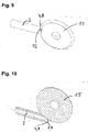
- Figure 9 shows a capillary tube 2 and a cutting disc 15 that is positioned here to provide the capillary tube 2 with a lateral opening at an end 4, 8 of the capillary tube 2 that goes through the entire cross-section of the capillary tube 2;
- Figure 10 shows a capillary tube 2 and a cutting disc 15 that is positioned here to provide the capillary tube 2 with a lateral opening at an end 4, 8 of the capillary tube 2 that goes through a part of the cross-section of the capillary tube 2.
Landscapes
- Engineering & Computer Science (AREA)
- Physics & Mathematics (AREA)
- Mechanical Engineering (AREA)
- Thermal Sciences (AREA)
- General Engineering & Computer Science (AREA)
- Chemical & Material Sciences (AREA)
- Analytical Chemistry (AREA)
- Power Engineering (AREA)
- Air-Conditioning For Vehicles (AREA)
- Heat-Pump Type And Storage Water Heaters (AREA)
Abstract
Description
- The invention relates to a heat pump having a capillary and a home appliance containing the heat pump. In particular, the invention relates to a heat pump, including an evaporator, a condenser, a compressor for driving and compressing a flow of a refrigerant, a capillary for expanding the refrigerant flow, and a refrigerant channel for circulating the refrigerant flow sequentially through the compressor, the condenser, the filter, the capillary, the evaporator, and the compressor, wherein the capillary is connected to the evaporator in a gas-tight and fluid-tight manner such that a first end of the capillary intrudes into the evaporator; and a home appliance containing the heat pump.
- Heat pumps are used in various fields of technology. A heat pump is a device which takes thermal energy from a reservoir with lower temperature, for example from the environment, and transfers it together with the drive energy as useful heat to a system to be heated with higher temperature. Heat pumps of this type can be used for example for heaters, dryers, washer-dryers, washing machines and dishwashers. A heat pump can also be used for cooling, e.g. in a refrigerator or in an air conditioner. The technical work is usually generated by means of electrical energy. It is desired to reduce the consumption of electrical energy and thus increase the energy efficiency of heat pumps. Another aim is to reduce the manufacturing costs of heat pumps. When heat pumps are used in dryers and washer-dryers, for example, drying times should also preferably be reduced. A known approach to achieve these goals is to reduce the diameter of the pipes carrying the refrigerant of the heat pump circuit. By reducing the diameter of the heat exchanger tubes, energy efficiency can be increased. Furthermore, reducing the diameter of the tubes can save material and thus reduce the manufacturing costs of the heat pump. However, the disadvantage here is that the pressure loss or pressure drop of the tubes can be increased by reducing the diameter of the tubes.
- Dryers and washer dryers with heat pumps usually use a capillary or a regulated expansion valve as a throttle. The capillary must have a correspondingly large length in order to be able to generate a sufficiently high pressure difference between the condenser and the evaporator.
- It is disadvantageous that the capillary has a significantly smaller diameter than the tube of the evaporator, but these two elements must be connected to one another in a fluid-tight or gas-tight manner in order to close the refrigerant circuit of the heat pump. Copper tubes are usually used for both the capillary and the tube of the evaporator, so that the end of the capillary can be inserted into the end of the tube of the evaporator and the end of the tube of the evaporator can be crimped around the end of the capillary by reshaping to establish this connection. This connection is usually also brazed.
- However, since the undefined result of the reshaping can make soldering more difficult, leaky soldering points can occur comparatively frequently at these points, so that no reliable gas and fluid-tight connection between the end of the capillary and the tube of the evaporator might be established.
- To avoid this, an adapter piece can be used at this point, which can form the transition between the respective diameters of the end of the capillary and the tube of the evaporator. The adapter piece can each have an opening which corresponds to one of the diameters of the end of the capillary and the end of the tube of the evaporator. The transitions from the end of the capillary to the adapter piece and from the adapter piece to the end of the tube of the evaporator must be brazed, but this can be done without reshaping and thus more defined and safer, so that the risk of leaks at these brazed points can be reduced. However, this requires additional material and manufacturing costs of the adapter piece and an increased number of brazing points.
- The connection between a capillary pipe and an evaporator is currently made with a capillary pipe adapter. On the other hand it is known to connect the capillary pipe directly to an elbow of the evaporator instead of using a capillary pipe adapter. In such a case, however, a blockage of refrigerant flow can occur. For example during an assembly process it might occur that the capillary pipe is introduced too much. The first end of the capillary pipe can then touch the internal wall of the elbow avoiding a correct flow of the refrigerant.
- The publication
DE 10 2017 109 065 B4 discloses a connection system for the gas-tight and fluid-tight connection of a condenser of a heat pump to an evaporator of the heat pump, the evaporator having at least two refrigerant passes, with a capillary and with a connecting element which is connected to the capillary in a gas-tight and fluid-tight manner, the connecting element having at least one first tube element, which is designed for connection to the first refrigerant pass of the evaporator, and at least one second tube element, which is designed for connection to the second refrigerant pass of the evaporator, the capillary having a passage for the passage of a refrigerant into the connecting element, wherein the passage of the capillary has at least one first outlet and at least one second outlet, which are arranged within the connecting element. Said publication discloses also a heat pump, with a condenser, with an evaporator with at least two refrigerant passes, and with at least one connection system described above, which connects the condenser to the evaporator in a gas-tight and fluid-tight manner. - In view of this situation it is an object of the present invention to provide an improved heat pump that does not show a blockage of refrigerant flow and that can be manufactured in an improved assembly process.
- This object is achieved according to the present invention with a heat pump, a process for the manufacture of the heat pump, and a home appliance according to the respective independent claims. Preferred embodiments of the heat pump and the process are defined in respective dependent claims, with preferred embodiments of the process and the home appliance corresponding to preferred embodiments of the heat pump, and vice versa, even if not expressly specified elsewhere herein.
- The invention is thus directed to a heat pump, including an evaporator, a condenser, a compressor for driving and compressing a flow of a refrigerant, a capillary for expanding the refrigerant flow, and a refrigerant channel for circulating the refrigerant flow sequentially through compressor, the condenser, the filter, the capillary, the evaporator, and the compressor, wherein the capillary is connected to the evaporator in a gas-tight and fluid-tight manner such that a first end of the capillary intrudes into the evaporator, wherein the capillary is a cylindrical tube with a lateral opening at its first end and/or at a second end thereof.
- In a preferred embodiment of the heat pump, the lateral opening or the lateral openings are obtainable by cutting the first end and/or the second end of the capillary correspondingly. The cut at the end of the capillary can be made by many methods, for example by punching, water jet, laser trimming or a cutting disc. It is moreover possible to have the cut performed through the entire cross section, i.e. through the entire capillary pipe diameter, or through only part of it.
- In a preferred embodiment of the heat pump, the cutting is performed by punching, water jet, laser trimming or a cutting disc.
- Moreover, as stated above, in a preferred embodiment of the heat pump, the lateral opening or the lateral openings extend over the entire inner cross section area Acs of the capillary.
- In another embodiment of the inventive heat pump, the lateral opening or the lateral openings extend over a part of the inner cross section Acs of the capillary.
- The desired shape of the lateral opening can be achieved by the proper use of a cutting device mentioned above.
- It is moreover preferred that a surface area Acut of the lateral opening or the lateral openings is ≥ inner cross section Acs of the capillary. In the heat pump of the present invention, the ratio Acut to Acs is preferably in the range of from 1 to 3.
- It is moreover preferred in the heat pump of the present invention that the capillary intrudes into an elbow of the evaporator.
- Preferably the heat pump contains a filter. In a preferred embodiment of the heat pump, the second end of the capillary faces a filter mesh of a filter for the refrigerant. In this regard, a heat pump is preferred wherein the second end of the capillary facing the filter mesh has a lateral opening with an opening area Acut 2 which is ≥ inner cross-section area Acs of the capillary.
- In a preferred embodiment of the heat pump, the first end of the capillary also has an opening with an opening area Acut 1 which is ≥ inner cross-section area Acs of the capillary.
- Numerous refrigerants can be used in the invention, for example propane, which is also known by the designation R290 in the field of heat pump technology.
- The capillary of the heat pump preferably contains or is made of copper.
- The invention is moreover directed to a process for the manufacture of a heat-pump including an evaporator, a condenser, a compressor for driving and compressing a flow of a refrigerant, a capillary for expanding the refrigerant flow, and a refrigerant channel for circulating the refrigerant flow sequentially through compressor, the condenser, the filter, the capillary, the evaporator, and the compressor, wherein the capillary is connected to the evaporator in a gas-tight and fluid-tight manner such that a first end of the capillary intrudes into the evaporator, wherein the capillary is a cylindrical tube with an opening at its first end and/or at a second end thereof, comprising the steps
- (a) providing a capillary; and
- (b) cutting the first end and/or the second end of the capillary.
- In a preferred process, the cutting in step (b) is performed by punching, water jet, laser trimming or a cutting disc.
- In the present invention, a lateral opening is present at least at one end of the capillary pipe. The first end and the second end of the capillary can be also termed first and second edge, respectively.
- The opening can be present over the entire surface of the capillary pipe, first end and/or second end of the capillary pipe.
- In the present invention, a lateral cut is usually performed on the edge of a capillary pipe end. It is preferred that the lateral opening has a surface which is at least equal to the capillary pipe internal cross section. Thus, in the case of the edge of a capillary pipe end touching another surface, at least one capillary pipe internal cross section is open to allow refrigerant flow.
- In a preferred embodiment, the cut is applied at the two ends of the capillary pipe, i.e. for a direct connection to an elbow of the evaporator used in a heat pump and for the other end of the capillary pipe, i.e. the second end, where there is usually a filter that in general contains a filter mesh. Namely, also in the case of a filter, if the capillary pipe is introduced too much, a capillary pipe end can touch the internal filter mesh and it can produce a blockage of refrigerant flow.
- The invention is finally directed to a home appliance comprising a heat-pump according to any of the preceding embodiments.
- The home appliance of the invention is preferably embodied as a laundry dryer for pieces of laundry, a washer-dryer which combines the function of washing laundry with the function of drying. Another embodiment is a dishwasher that performs drying of tableware by applying a heat pump circuit. In a laundry dryer or a washer-dryer the drying chamber is in general a rotatable drum.
- According to a further aspect of the present invention, the evaporator is connected to the capillary in a gas-tight and fluid-tight manner by means of a material connection, preferably by gluing, welding, brazing or soldering, particularly preferably by brazing.
- The invention has several advantages. The manufacture of the heat pump can be significantly improved. The manufacture can be achieved by applying simple, cheap and quickly assembled means. The tack time in an assembly process can be reduced since it is not necessary to pay attention to the length of the introduced capillary length. The capillary can be produced in a simple and inexpensive manner.
- Further details of the invention will appear from the subsequent description of specific embodiments with references to the following Figures, wherein
- Figure 1
- shows a perspective view of a section of an evaporator (elbow) of a heat pump to which is connected a capillary tube;
- Figure 2
- shows a perspective view of the enlarged, vertically cut section shown in
Figure 1 ; - Figure 3
- shows a front view of the cut section shown in
Figure 2 ; - Figure 4
- shows a perspective view of a filter used in an embodiment of the heat pump to which a capillary tube is attached;
- Figure 5
- shows a perspective view of a cut through the filter shown in
Figure 4 wherein a filter mesh can be seen that is touched by the capillary tube; - Figure 6
- shows a front view of a cut through the filter shown in
Figure 4 wherein a filter mesh can be seen that is touched by the capillary tube with a lateral opening at its second end; - Figure 7
- shows a capillary tube with a lateral opening at an end of the capillary tube that goes through the entire cross-section of the capillary;
- Figure 8
- shows a capillary tube with a lateral opening at an end of the capillary tube that goes through a part of the cross-section of the capillary;
- Figure 9
- shows a capillary tube and a cutting disc that is positioned here to provide the capillary tube with a lateral opening at an end of the capillary tube that goes through the entire cross-section of the capillary tube; and
- Figure 10
- shows a capillary tube and a cutting disc that is positioned here to provide the capillary tube with a lateral opening at an end of the capillary tube that goes through a part of the cross-section of the capillary tube.
-
Figure 1 shows a perspective view of a section of an evaporator 1 of a heat pump to which is connected acapillary tube 2. Thecapillary tube 2 is connected to an elbow 18 of the evaporator. 3 refers to the refrigerant channel within thecapillary tube 2. -
Figure 2 shows a perspective view of the enlarged, vertically cut section shown inFigure 1 . The reference signs have the same meaning as forFigure 1 . Therefrigerant channel 3 can be seen here more clearly. -
Figure 3 shows a front view of the cut section shown inFigure 2 . The reference signs have the same meaning as forFigure 1 . -
Figure 4 shows a perspective view of afilter 14 used in an embodiment of the heat pump to which acapillary tube 2 is attached. -
Figure 5 shows a perspective view of a cut through thefilter 14 shown inFigure 4 wherein afilter mesh 13 can be seen that is touched by thecapillary tube 2. -
Figure 6 shows a front view of a cut through thefilter 14 shown inFigure 4 wherein afilter mesh 13 can be seen that is touched by thecapillary tube 2 which has alateral opening 7 at itssecond end 8. -
Figure 7 shows acapillary tube 2 with a lateral opening at anend 4, 8 of thecapillary tube 2 that goes through the entire cross-section of thecapillary 2; -
Figure 8 shows acapillary tube 2 with a lateral opening at anend 4, 8 of thecapillary tube 2 that goes through a part of the cross-section of thecapillary 2; -
Figure 9 shows acapillary tube 2 and acutting disc 15 that is positioned here to provide thecapillary tube 2 with a lateral opening at anend 4, 8 of thecapillary tube 2 that goes through the entire cross-section of thecapillary tube 2; and -
Figure 10 shows acapillary tube 2 and acutting disc 15 that is positioned here to provide thecapillary tube 2 with a lateral opening at anend 4, 8 of thecapillary tube 2 that goes through a part of the cross-section of thecapillary tube 2. -
- 1
- Evaporator
- 2
- Capillary
- 3
- Refrigerant channel
- 4
- First end of the capillary
- 5
- Cylindrical tube
- 6
- Lateral opening at the first end of the capillary
- 7
- Lateral opening at the second end of the capillary
- 8
- Second end of the capillary
- 9
- Inner cross section area Acs of the capillary
- 10
- Part of the inner cross section Acs of the capillary over which the opening extends
- 11
- Surface area Acut 1 of the opening at the first end of the capillary
- 12
- Surface area Acut 2 of the opening at the second end of the capillary
- 13
- Filter mesh
- 14
- Filter
- 15
- Cutting disc
- 16
- Lateral opening through the entire capillary
- 17
- Lateral opening through part of the capillary
- 18
- Elbow of an evaporator
Claims (15)
- Heat pump, including an evaporator (1), a condenser, a compressor for driving and compressing a flow of a refrigerant, a capillary (2) for expanding the refrigerant flow, and a refrigerant channel (3) for circulating the refrigerant flow sequentially through the compressor, the condenser, the filter (14), the capillary (2), the evaporator (1), and the compressor, wherein the capillary (2) is connected to the evaporator (1) in a gas-tight and fluid-tight manner such that a first end (4) of the capillary (2) intrudes into the evaporator (1), characterized in that the capillary (2) is a cylindrical tube (5) with a lateral opening (6,7) at its first end (4) and/or at a second end (8) thereof.
- Heat pump according to claim 1, wherein the lateral opening (6) or the openings (6,7) are obtainable by cutting the first end (4) and/or the second end (8) of the capillary (2).
- Heat pump according to claim 1 or 2, wherein the cutting is performed by punching, water jet, laser trimming or a cutting disc.
- Heat pump according to any of claims 1 to 3, wherein the lateral opening (6) or the lateral openings (6,7) extend over the entire inner cross section area Acs (9) of the capillary (2).
- Heat pump according to any of claims 1 to 3, wherein the lateral opening (6) or the lateral openings (6,7) extend over a part (10) of the inner cross section Acs (9) of the capillary (2).
- Heat pump according to any of claims 1 to 5, wherein a surface area Acut (11,12) of the opening (6) or the openings (6,7) is ≥ inner cross section Acs (9) of the capillary (2).
- Heat-pump according to any of claims 1 to 6, wherein the ratio Acut (11,12) to Acs (9) is in the range of from 1 to 3.
- Heat pump according to any of claims 1 to 7, wherein the capillary (2) intrudes into an elbow (18) of the evaporator (1).
- Heat pump according to any of claims 1 to 7, wherein the second end (8) of the capillary (2) faces a filter mesh (13) of a filter (14) for the refrigerant.
- Heat pump according to claim 9, wherein the second end (8) of the capillary (2) facing the filter mesh (13) has an opening (7) with an opening area Acut 2 which is ≥ inner cross-section area Qcs of the capillary (2).
- Heat pump according to any of claims 1 to 10, wherein the first end (4) of the capillary (2) facing the filter mesh (13) has an opening (6) with an opening area Acut 1 which is ≥ inner cross-section area Acs of the capillary (2).
- Heat pump according to any of claims 1 to 11, wherein the capillary (2) contains or is made of copper.
- Process for the manufacture of a heat pump including an evaporator (1), a condenser, a compressor for driving and compressing a flow of a refrigerant, a capillary (2) for expanding the refrigerant flow, and a refrigerant channel (3) for circulating the refrigerant flow sequentially through the compressor, the condenser, the filter (14), the capillary (2), the evaporator (1), and the compressor, wherein the capillary (2) is connected to the evaporator (1) in a gas-tight and fluid-tight manner such that a first end (4) of the capillary (2) intrudes into the evaporator (1), wherein the capillary (2) is a cylindrical tube (5) with an opening (6,7) at its first end (4) and/or at a second end (8) thereof, comprising the steps(a) providing a capillary (2); and(b) cutting the first end (4) and/or the second end (8) of the capillary (2).
- Process according to claim 13, wherein the cutting of step (b) is performed by punching, water jet, laser trimming or a cutting disc.
- A home appliance comprising a heat pump according to any of claims 1 to 12.
Applications Claiming Priority (1)
| Application Number | Priority Date | Filing Date | Title |
|---|---|---|---|
| EP21382859 | 2021-09-24 |
Publications (1)
| Publication Number | Publication Date |
|---|---|
| EP4155628A1 true EP4155628A1 (en) | 2023-03-29 |
Family
ID=78413910
Family Applications (1)
| Application Number | Title | Priority Date | Filing Date |
|---|---|---|---|
| EP22196206.1A Pending EP4155628A1 (en) | 2021-09-24 | 2022-09-16 | Heat pump having a capillary, home appliance containing the heat pump and a process for manufacturing a heat pump |
Country Status (2)
| Country | Link |
|---|---|
| EP (1) | EP4155628A1 (en) |
| CN (1) | CN115854602A (en) |
Citations (3)
| Publication number | Priority date | Publication date | Assignee | Title |
|---|---|---|---|---|
| EP2562490A1 (en) * | 2010-04-22 | 2013-02-27 | Panasonic Corporation | Refrigerator |
| EP2667130A1 (en) * | 2011-01-17 | 2013-11-27 | Martinez Aroca, Jose Antonio | Electrical appliance that can also be used in industry for cooling or freezing products with maximum speed |
| DE102017109065B4 (en) | 2017-04-27 | 2019-06-06 | Miele & Cie. Kg | Connection system for gas- and fluid-tight connection of a condenser of a heat pump with a heat pump evaporator |
-
2022
- 2022-09-16 EP EP22196206.1A patent/EP4155628A1/en active Pending
- 2022-09-21 CN CN202211150311.7A patent/CN115854602A/en active Pending
Patent Citations (3)
| Publication number | Priority date | Publication date | Assignee | Title |
|---|---|---|---|---|
| EP2562490A1 (en) * | 2010-04-22 | 2013-02-27 | Panasonic Corporation | Refrigerator |
| EP2667130A1 (en) * | 2011-01-17 | 2013-11-27 | Martinez Aroca, Jose Antonio | Electrical appliance that can also be used in industry for cooling or freezing products with maximum speed |
| DE102017109065B4 (en) | 2017-04-27 | 2019-06-06 | Miele & Cie. Kg | Connection system for gas- and fluid-tight connection of a condenser of a heat pump with a heat pump evaporator |
Also Published As
| Publication number | Publication date |
|---|---|
| CN115854602A (en) | 2023-03-28 |
Similar Documents
| Publication | Publication Date | Title |
|---|---|---|
| JP6333401B2 (en) | Heat exchanger and air conditioner | |
| JP2005083741A (en) | Air conditioner having heat exchanger and refrigerant switching means | |
| EP2184565A1 (en) | Heating device for refrigerant | |
| JPWO2017109933A1 (en) | HEAT EXCHANGER, AIR CONDITIONER HAVING THE SAME, AND METHOD FOR MANUFACTURING FLAT TUBE BEND | |
| KR20040082571A (en) | Fin and tube solid type heat exchanger | |
| CN1523312B (en) | Multi-type air conditioner and method for controlling operation of the same | |
| EP4283220A1 (en) | Gas collecting pipe assembly | |
| CN115854602A (en) | Heat pump with capillary tube and household appliance including heat pump | |
| JP6656368B2 (en) | Fin tube type heat exchanger and heat pump device provided with this fin tube type heat exchanger | |
| JP2008039298A (en) | Heat pump cycle | |
| JP2013134024A (en) | Refrigeration cycle device | |
| JP5525763B2 (en) | Heat transfer tube, heat exchanger, and air conditioner equipped with the heat exchanger | |
| JP2016095039A (en) | Refrigeration cycle equipment | |
| KR20220056855A (en) | Expansion device for refrigeration units | |
| KR20090071730A (en) | Inlet refrigerant pipe for evaporator of air conditioner | |
| JP2020076569A (en) | Heat exchanger manufacturing method | |
| JP7706580B2 (en) | Refrigerant distributor, heat exchanger and refrigeration cycle device | |
| JP4702411B2 (en) | Evaporator | |
| KR102385752B1 (en) | Heat exchange assembly for refrigeration cycle and manufacturing method therof | |
| JP2020076531A (en) | Heat exchanger and air conditioner including the same | |
| JP2006242443A (en) | Air conditioner | |
| WO2025120791A1 (en) | Air conditioner | |
| KR20040037684A (en) | Drainage apparatus for regenerator | |
| JP2024178519A (en) | Air conditioner and method for manufacturing heat exchanger | |
| KR100517925B1 (en) | Fin and tube solid type heat exchanger |
Legal Events
| Date | Code | Title | Description |
|---|---|---|---|
| PUAI | Public reference made under article 153(3) epc to a published international application that has entered the european phase |
Free format text: ORIGINAL CODE: 0009012 |
|
| STAA | Information on the status of an ep patent application or granted ep patent |
Free format text: STATUS: THE APPLICATION HAS BEEN PUBLISHED |
|
| AK | Designated contracting states |
Kind code of ref document: A1 Designated state(s): AL AT BE BG CH CY CZ DE DK EE ES FI FR GB GR HR HU IE IS IT LI LT LU LV MC MK MT NL NO PL PT RO RS SE SI SK SM TR |
|
| STAA | Information on the status of an ep patent application or granted ep patent |
Free format text: STATUS: REQUEST FOR EXAMINATION WAS MADE |
|
| 17P | Request for examination filed |
Effective date: 20230929 |
|
| RBV | Designated contracting states (corrected) |
Designated state(s): AL AT BE BG CH CY CZ DE DK EE ES FI FR GB GR HR HU IE IS IT LI LT LU LV MC MK MT NL NO PL PT RO RS SE SI SK SM TR |