EP4155620B1 - Water heater and methods to operate a water heater - Google Patents
Water heater and methods to operate a water heater Download PDFInfo
- Publication number
- EP4155620B1 EP4155620B1 EP21198629.4A EP21198629A EP4155620B1 EP 4155620 B1 EP4155620 B1 EP 4155620B1 EP 21198629 A EP21198629 A EP 21198629A EP 4155620 B1 EP4155620 B1 EP 4155620B1
- Authority
- EP
- European Patent Office
- Prior art keywords
- water
- valve
- siphon
- trap
- heated
- Prior art date
- Legal status (The legal status is an assumption and is not a legal conclusion. Google has not performed a legal analysis and makes no representation as to the accuracy of the status listed.)
- Active
Links
Images



Classifications
-
- F—MECHANICAL ENGINEERING; LIGHTING; HEATING; WEAPONS; BLASTING
- F24—HEATING; RANGES; VENTILATING
- F24H—FLUID HEATERS, e.g. WATER OR AIR HEATERS, HAVING HEAT-GENERATING MEANS, e.g. HEAT PUMPS, IN GENERAL
- F24H8/00—Fluid heaters characterised by means for extracting latent heat from flue gases by means of condensation
-
- F—MECHANICAL ENGINEERING; LIGHTING; HEATING; WEAPONS; BLASTING
- F24—HEATING; RANGES; VENTILATING
- F24H—FLUID HEATERS, e.g. WATER OR AIR HEATERS, HAVING HEAT-GENERATING MEANS, e.g. HEAT PUMPS, IN GENERAL
- F24H9/00—Details
- F24H9/16—Arrangements for water drainage
-
- F—MECHANICAL ENGINEERING; LIGHTING; HEATING; WEAPONS; BLASTING
- F24—HEATING; RANGES; VENTILATING
- F24D—DOMESTIC- OR SPACE-HEATING SYSTEMS, e.g. CENTRAL HEATING SYSTEMS; DOMESTIC HOT-WATER SUPPLY SYSTEMS; ELEMENTS OR COMPONENTS THEREFOR
- F24D17/00—Domestic hot-water supply systems
- F24D17/0026—Domestic hot-water supply systems with conventional heating means
-
- F—MECHANICAL ENGINEERING; LIGHTING; HEATING; WEAPONS; BLASTING
- F24—HEATING; RANGES; VENTILATING
- F24D—DOMESTIC- OR SPACE-HEATING SYSTEMS, e.g. CENTRAL HEATING SYSTEMS; DOMESTIC HOT-WATER SUPPLY SYSTEMS; ELEMENTS OR COMPONENTS THEREFOR
- F24D19/00—Details
- F24D19/0092—Devices for preventing or removing corrosion, slime or scale
-
- F—MECHANICAL ENGINEERING; LIGHTING; HEATING; WEAPONS; BLASTING
- F24—HEATING; RANGES; VENTILATING
- F24H—FLUID HEATERS, e.g. WATER OR AIR HEATERS, HAVING HEAT-GENERATING MEANS, e.g. HEAT PUMPS, IN GENERAL
- F24H15/00—Control of fluid heaters
- F24H15/30—Control of fluid heaters characterised by control outputs; characterised by the components to be controlled
- F24H15/305—Control of valves
- F24H15/31—Control of valves of valves having only one inlet port and one outlet port, e.g. flow rate regulating valves
-
- F—MECHANICAL ENGINEERING; LIGHTING; HEATING; WEAPONS; BLASTING
- F24—HEATING; RANGES; VENTILATING
- F24H—FLUID HEATERS, e.g. WATER OR AIR HEATERS, HAVING HEAT-GENERATING MEANS, e.g. HEAT PUMPS, IN GENERAL
- F24H15/00—Control of fluid heaters
- F24H15/30—Control of fluid heaters characterised by control outputs; characterised by the components to be controlled
- F24H15/305—Control of valves
- F24H15/32—Control of valves of switching valves
-
- F—MECHANICAL ENGINEERING; LIGHTING; HEATING; WEAPONS; BLASTING
- F24—HEATING; RANGES; VENTILATING
- F24H—FLUID HEATERS, e.g. WATER OR AIR HEATERS, HAVING HEAT-GENERATING MEANS, e.g. HEAT PUMPS, IN GENERAL
- F24H8/00—Fluid heaters characterised by means for extracting latent heat from flue gases by means of condensation
- F24H8/006—Means for removing condensate from the heater
-
- F—MECHANICAL ENGINEERING; LIGHTING; HEATING; WEAPONS; BLASTING
- F24—HEATING; RANGES; VENTILATING
- F24H—FLUID HEATERS, e.g. WATER OR AIR HEATERS, HAVING HEAT-GENERATING MEANS, e.g. HEAT PUMPS, IN GENERAL
- F24H9/00—Details
- F24H9/0005—Details for water heaters
- F24H9/0042—Cleaning arrangements
-
- F—MECHANICAL ENGINEERING; LIGHTING; HEATING; WEAPONS; BLASTING
- F24—HEATING; RANGES; VENTILATING
- F24H—FLUID HEATERS, e.g. WATER OR AIR HEATERS, HAVING HEAT-GENERATING MEANS, e.g. HEAT PUMPS, IN GENERAL
- F24H9/00—Details
- F24H9/20—Arrangement or mounting of control or safety devices
- F24H9/2007—Arrangement or mounting of control or safety devices for water heaters
- F24H9/2035—Arrangement or mounting of control or safety devices for water heaters using fluid fuel
-
- F—MECHANICAL ENGINEERING; LIGHTING; HEATING; WEAPONS; BLASTING
- F24—HEATING; RANGES; VENTILATING
- F24H—FLUID HEATERS, e.g. WATER OR AIR HEATERS, HAVING HEAT-GENERATING MEANS, e.g. HEAT PUMPS, IN GENERAL
- F24H1/00—Water heaters, e.g. boilers, continuous-flow heaters or water-storage heaters
- F24H1/48—Water heaters for central heating incorporating heaters for domestic water
- F24H1/52—Water heaters for central heating incorporating heaters for domestic water incorporating heat exchangers for domestic water
-
- Y—GENERAL TAGGING OF NEW TECHNOLOGICAL DEVELOPMENTS; GENERAL TAGGING OF CROSS-SECTIONAL TECHNOLOGIES SPANNING OVER SEVERAL SECTIONS OF THE IPC; TECHNICAL SUBJECTS COVERED BY FORMER USPC CROSS-REFERENCE ART COLLECTIONS [XRACs] AND DIGESTS
- Y02—TECHNOLOGIES OR APPLICATIONS FOR MITIGATION OR ADAPTATION AGAINST CLIMATE CHANGE
- Y02B—CLIMATE CHANGE MITIGATION TECHNOLOGIES RELATED TO BUILDINGS, e.g. HOUSING, HOUSE APPLIANCES OR RELATED END-USER APPLICATIONS
- Y02B30/00—Energy efficient heating, ventilation or air conditioning [HVAC]
Definitions
- the invention relates to a water heater. Further on, the invention relates to methods to operate a water heater.
- EP 1 063 481 B1 discloses a water heater comprising a gas burner being configured to combust gas if a heat demand is present, further comprising a heat exchanger being configured to heat water using the thermal energy provided with the combustion of the gas, further comprising an input pipe being configured to provide water to be heated to the heat exchanger, further comprising an output pipe being configured to provide water heated by the heat exchanger to the at least one water consumer, and further comprising a connecting pipe, namely a bypass pipe, extending between the input pipe and the output pipe.
- the gas burner comprises a burner chamber in which the combustion of the gas takes place.
- the gas burner further comprises a gas armature providing the gas to be combusted to the burner chamber. Both, the burner chamber and the gas armature from part of the gas burner.
- the gas burner of a water heater needs to be calibrated from time to time.
- the gas burner needs to be operated at a defined calibration burner load for a defined calibration time interval.
- a calibration of the gas burner can only be executed when a heat demand is present, namely if heated water is requested by at least one water consumer.
- the operation of the gas burner at the defined calibration burner load for the defined calibration time interval can lead to a water temperature at the respective water consumer being either too high or too low. This is a significant disadvantage of water heaters known from prior art.
- the invention provides a water heater according to claim 1.
- the water heater comprises a gas burner being configured to combust gas if a heat demand is present, namely if heated water is requested by at least one water consumer.
- the water heater further comprises a heat exchanger being configured to heat water using the thermal energy provided with the combustion of the gas, wherein the heat exchanger is a condensing heat exchanger.
- the water heater further comprises an input pipe being configured to provide water to be heated to the heat exchanger.
- the water heater further comprises an output pipe being configured to provide water heated by the heat exchanger to the at least one water consumer.
- the water heater further comprises a siphon or trap being configured to collect condensate resulting at the condensing heat exchanger during operation of the water heater.
- the water heater further comprises a first connection pipe and a valve acting together with the first connection pipe, both the first connection pipe and the valve are configured to guide water heated by heat exchanger from the output pipe to the siphon or trap, and/or to guide water not heated by the heat exchanger from the output pipe to the siphon or trap.
- the water heater further comprises a second connecting pipe extending between the input pipe and the output pipe.
- a separate valve acts together with the second connection pipe being configured to guide water from input pipe to the output pipe.
- the first connecting pipe extends between the second connecting pipe and the siphon or trap.
- the valve acting together with the first connection pipe is provided by a 3-way-valve connected between the first connecting pipe and the second connecting pipe. Said valve acts also together with the second connection pipe, wherein a first port of the 3-way-valve is connected to the output pipe through a first section of the second connecting pipe, wherein a second port of the 3-way-valve is connected to the input pipe through a second section of the second connecting pipe, and wherein a third port of the 3-way-valve is connected to the siphon or trap through the first connecting pipe.
- water heated by heat exchanger and water not heated by the heat exchanger can be guided from the output pipe to the siphon or trap through the first connection pipe and the valve acting together with the first connection pipe.
- the novel water heater can be operated with the gas burner combusting gas even if there is no heat demand by a water consumer.
- Calibrations of the water heater can be executed even if there is no heat demand by a water consumer.
- the water heated by the water heater during such a calibration can be guided to the siphon or trap.
- the valve acting together with the first connection pipe is a 2-way valve positioned within the first connection pipe, wherein a first port of the 2-way-valve is connected to the output pipe through a first section of the first connecting pipe, and wherein a second port of the 2-way-valve is connected to the siphon or trap through a second section of the first connecting pipe.
- a first port of the 2-way-valve is connected to the output pipe through a first section of the first connecting pipe
- a second port of the 2-way-valve is connected to the siphon or trap through a second section of the first connecting pipe.
- the valve acting together with the first connection pipe is a 3-way valve, wherein a first port of the 3-way-valve is connected to the heat exchanger through a first section of the output pipe, wherein a second port of the 3-way-valve is connected to the at least one water consumer through a second section of the output pipe, and wherein a third port of the 3-way-valve is connected to the siphon or trap through the first connecting pipe.
- a first port of the 3-way-valve is connected to the heat exchanger through a first section of the output pipe
- a second port of the 3-way-valve is connected to the at least one water consumer through a second section of the output pipe
- a third port of the 3-way-valve is connected to the siphon or trap through the first connecting pipe.
- the invention provides methods to operate a water heater according to claims 5, 7, 9, 11 and 12.
- FIGS 1 and 2 each show a water heater 10.
- the water heater 10 comprises a gas burner 11 being configured to combust a gas if a heat demand is present, namely if heated water is requested by at least one water consumer 24.
- the gas burner comprises 11 a burner chamber 12.
- a burner rod 13 of the gas burner 11 is positioned within the burner chamber 11.
- Gas 14 is provided to the burner rod 13 for combusting the gas 14 within the burner chamber 12.
- the gas 14 is preferably provided as a gas/air mixture 28.
- the combustion of the gas 14 of gas/air mixture 28 results into flames 16 and exhaust gas 15.
- the exhaust gas 15 emerges from the burner chamber 12 through a chimney.
- the gas 14 is preferably provided as a gas/air mixture 28.
- a gas/air mixture 28 is usually provided by a gas armature 30 of the gas burner 11.
- gas armatures 30 are well known.
- Such a gas armature 30 usually comprises a fan (not shown) proving a flow of air 29, a gas valve or gas modulator (not shown) providing a flow of the gas 14 and a mixing unit (not shown) mixing the air flow with the gas flow.
- the mixing ratio of gas 14 and air 29 within the gas/air mixture 28 is usually kept at a defined value over the entire modulation rage of the gas burner 11 such that at any burner load of the gas burner 11 the mixing ratio of the gas/air mixture 28 is kept at the defined value.
- the water heater 10 further comprises a heat exchanger 17 being configured to heat water using the thermal energy provided with the combustion of the gas 14.
- the heat exchanger 17 is positioned inside the burner chamber 12.
- the heat exchanger 17 is a condensing heat exchanger.
- the water heater 10 further comprises an input pipe 18 being configured to provide unheated water, namely water to be heated by the heat exchanger 17, to the heat exchanger 17.
- the water heater 10 further comprises an output pipe 19 being configured to provide water heated by the heat exchanger 17 to the at least one water consumer 24.
- the water heater 10 further comprises a siphon or trap 22 being configured to collect condensate resulting at the condensing heat exchanger 17 during operation of the water heater 10.
- the water heater 10 further comprises a first connecting pipe 21 and a valve 23 acting together with the first connection pipe 21. Both the first connection pipe 21 and the valve 23 are configured to guide water heated by heat exchanger 17 from the output pipe 19 to the siphon or trap 22, and to guide water not heated by the heat exchanger 17 from the output pipe 19 to the siphon or trap 22.
- the first connection pipe 21 extends between the output pipe 19 and the siphon or trap 22.
- the valve 23 acting together with the first connection pipe 21 is a 2-way valve positioned within the first connection pipe 21, wherein a first port 23a of the 2-way-valve is connected to the output pipe 19 through a first section 21a of the first connecting pipe 21, and wherein a second port 23b of the 2-way-valve is connected to the siphon or trap 22 through a second section 21b of the first connecting pipe 21.
- Figure 2 according to a first embodiment of the invention shows a modification of water heater 10 of Figure 1 .
- the water heater 10 comprises further a second connecting pipe 20 extending between the input pipe 18 and the output pipe 19, and a separate valve 26 acting together with the second connection pipe 20 being configured to guide water from input pipe 18 to the output pipe 19.
- a first section 20a of the second connecting pipe 20 extends between the output pipe 19 and the separate valve 26.
- a second section 20a of the second connecting pipe 20 extends between the input pipe 18 and the separate valve 26. All other details of the water heater of Figure 2 are identical to the water heater of Figure 1 .
- the second connecting pipe 20 may also be called bypass pipe.
- the input pipe 18 provides water to the heat exchanger 17, said water becomes heated by the heat exchanger 17 when flowing through the same using the thermal energy resulting from the combustion of the gas 14 by the gas burner 11, and the water heated by the heat exchanger 17 is provided to the respective water consumer 24.
- the valve 23 is closed.
- the valve 26 may be opened or closed in this situation. If the valve 26 is closed in this situation, only water heated by the heat exchanger 17 is provided to the respective water consumer 24.
- the gas burner 11 may be active and may combust gas 14 or may inactive and may not combust gas 14.
- water heated by the heat exchanger 17 can be provided to the siphon or trap 22 from the output pipe 19 through the first connecting pipe 21 and through the valve 23.
- heated water as well as unheated water can be provided to the siphon or trap 22 without any water consumption at a water consumer 24.
- the water heater 10 is operated as follows: The gas burner 11 is operated at a defined calibration burner load for a defined calibration time interval and the water heated by the heat exchanger 17 during the calibration is provided by the valve 23 to the siphon or trap 22. During the calibration, the heated water is provided by the valve 23 to the siphon or trap 22 from the output pipe 19, namely in such a way that the heated water flows from the output pipe 19 through the first section 21a of the first connecting pipe 21, through the valve 23 and through the second section 21b of the first connecting pipe 21 to the siphon or trap 22.
- the water heater 10 is operated as follows: Unheated water or heated water is provided by the valve 23 to the siphon or trap 22.
- the unheated water or the heated water is provided by the valve 23 to the siphon or trap 22 from the output pipe 19.
- the gas burner 11 is combusting gas 14 at a defined burner load.
- the gas burner 11 is not combusting gas 14.
- the heated water or the unheated water is provided by the valve 23 to the siphon or trap 22 from the output pipe 19, namely in such a way that the water flows from the output pipe 19 through the first section 21a of the first connecting pipe 21, through the valve 23 and through the second section 21b of the first connecting pipe 21 to the siphon or trap 22.
- the water heater 10 of Figures 1 and 2 is operated as follows: Unheated water or heated water is provided by the valve 23 to the siphon or trap 22. Unheated water or heated water is provided by the valve 23 to the siphon or trap 22. Preferably, the unheated water or the heated water is provided by the valve 23 to the siphon or trap 22 from the output pipe 19.
- the gas burner 11 is combusting gas 14 at a defined burner load.
- the gas burner 11 is not combusting gas 14.
- the heated water or the unheated water is provided by the valve 23 to the siphon or trap 22 from the output pipe 19, namely in such a way that the water flows from the output pipe 19 through the first section 21a of the first connecting pipe 21, through the valve 23 and through the second section 21b of the first connecting pipe 21 to the siphon or trap 22.
- Step i) Combust gas with the gas burner 11 at a defined burner load for a defined first time interval and provide the heated water to the siphon or trap 22.
- Step i) Combust gas with the gas burner 11 at a defined first burner load for a defined first time interval and provide the heated water to the siphon or trap 22.
- Step ii) combust gas with the gas burner 11 at a defined second burner load for a defined second time interval and provide the heated water to the siphon or trap 22, wherein the first burner load is relatively low compared to the second burner load.
- the first burner load may be a minimum burner load and the second burner load may be a maximum burner load.
- the water is provided from the output pipe 19 to the siphon or trap 22 through the valve 23, namely in such a way that the water flows from the output pipe 19 through the first section 21a of the first connecting pipe 21, through the valve 23 and through the second section 21b of the first connecting pipe 21 to the siphon or trap 22.
- Figures 3 and 4 both show a water heater 10.
- the comparative water heater of Figure 3 differs from the comparative water heater of Figure 1 and the water heater of Figure 4 according to a second embodiment of the invention differs from the water heater of Figure 2 according the first embodiment of the invention merely by the design of the respective valve 23, 25 acting together with first connection pipe 21. While in Figures 1 and 2 said valve 23 is provided by a 2-way-valve, in Figures 3 and 4 said valve 25 is provided by a 3-way-valve.
- a first port 25a of the 3-way-valve is connected to the heat exchanger 17 through a first section 19a of the output pipe 19, wherein a second port 25b of the 3-way-valve is connected to the at least one water consumer 24 through a second section 19b of the output pipe 19, and wherein a third port 25c of the 3-way-valve is connected to the siphon or trap 22 through the first connecting pipe 21.
- Figure 4 differs from Figure 3 merely by the second connecting pipe 20 extending between the input pipe 18 and the output pipe 19, and by the separate valve 26 acting together with second connection pipe 20 being configured to guide water from input pipe 18 to the output pipe 19.
- both the first connection pipe 21 and the respective valve 23, 25 are configured to guide water heated by heat exchanger 17 from the output pipe 19 to the siphon or trap 22, and to guide water not heated by the heat exchanger 17 from the output pipe 19 to the siphon or trap 22.
- the second connecting pipe 20 may also be called bypass pipe.
- the input pipe 18 provides water to the heat exchanger 17, said water becomes heated by the heat exchanger 17 when flowing through the same using the thermal energy resulting from the combustion of the gas 14 by the gas burner 11, and the water heated by the heat exchanger 17 is provided to the respective water consumer 24.
- the ports 25a, 25b of the valve 25 are opened and the port 25c of the valve 25 is closed.
- the valve 26 may be opened or closed in this situation. If the valve 26 is closed in this situation, only water heated by the heat exchanger 17 is provided to the respective water consumer 24.
- the gas burner 11 may be active and may combust gas 14 or may inactive and may not combust gas 14.
- water heated by the heat exchanger 17 can be provided to the siphon or trap 22 from the output pipe 19 through the first connecting pipe 21 and through the valve 25.
- the water heater 10 is operated as follows: The gas burner 11 is operated at a defined calibration burner load for a defined calibration time interval and the water heated by the heat exchanger 17 during the calibration is provided by the valve 25 to the siphon or trap 22. In this situation the ports 25a, 25c of the valve 25 are opened and the port 25b of the valve 25 is closed.
- the heated water is provided by the valve 25 to the siphon or trap 22 from the output pipe 19, namely in such a way that the heated water flows from the first section 19a of the output pipe 19 through the valve 25 and through the first connecting pipe 21 to the siphon or trap 22.
- the water heater 10 is operated as follows: Unheated water or heated water is provided by the valve 25 to the siphon or trap 22. Preferably, the unheated water or the heated water is provided by the valve 25 to the siphon or trap 22 from the output pipe 19. To provide heated water to the siphon or trap 22, the gas burner 11 is combusting gas 14 at a defined burner load. To provide unheated water to the siphon or trap 22, the gas burner 11 is not combusting gas 14.
- the heated water or the unheated water is provided by the valve 25 to the siphon or trap 22 from the output pipe 19, namely in such a way that the water flows from the first section 19a of the output pipe 19 through the valve 25 and through the first connecting pipe 21 to the siphon or trap 22.
- the water heater 10 of Figures 3 and 4 is operated as follows: Unheated water or heated water is provided by the valve 25 to the siphon or trap 22. Unheated water or heated water is provided by the valve 25 to the siphon or trap 22. Preferably, the unheated water or the heated water is provided by the valve 25 to the siphon or trap 22 from the output pipe 19. To provide heated water to the siphon or trap 22, the gas burner 11 is combusting gas 14 at a defined burner load. To provide unheated water to the siphon or trap 22, the gas burner 11 is not combusting gas 14.
- the heated water or the unheated water is provided by the valve 25 to the siphon or trap 22 from the output pipe 19, namely in such a way that the water flows from the first section 19a of the output pipe 19 through the valve 25 and through the first connecting pipe 21 to the siphon or trap 22.
- Step i) Combust gas with the gas burner 11 at a defined burner load for a defined first time interval and provide the heated water to the siphon or trap 22.
- Step i) Combust gas with the gas burner 11 at a defined first burner load for a defined first time interval and provide the heated water to the siphon or trap 22.
- Step ii) combust gas with the gas burner 11 at a defined second burner load for a defined second time interval and provide the heated water to the siphon or trap 22, wherein the first burner load is relatively low compared to the second burner load.
- the first burner load may be a minimum burner load and the second burner load may be a maximum burner load.
- the water is provided from the output pipe 19 to the siphon or trap 22 through the valve 25, namely in such a way that the water flows from the first section 19a of the output pipe 19 through the valve 25 and through the first connecting pipe 21 to the siphon or trap 22.
- Figures 5 both shows a water heater 10 according to a third embodiment of the present invention.
- the water heater 10 of Figure 5 mandatorily comprises the second connecting pipe 20 extending between the input pipe 18 and the output pipe 19.
- the second connecting pipe 20 may also be called bypass pipe.
- the first connecting pipe 21 extends between the second connecting pipe 20 and the siphon or trap 22.
- the water heater of Figure 5 further comprises a valve 27 connected between the first connecting pipe 21 and the second connecting pipe 22.
- Said valve 27 is configured to guide water heated by heat exchanger 17 from the output pipe 19 to the siphon or trap 22, and to guide water unheated by the heat exchanger 17 but flowing through the same from the output pipe 19 to the siphon or trap 22. This can be done even if no heat demand is present, namely if heated water is not requested by the at least one water consumer 24.
- Said valve 27 is also configured to guide unheated water bypassing the heat exchanger 18 from the input pipe 18 to the siphon or trap 22.
- the valve 27 of Figure 5 is a 3-way-valve.
- a first port 27a of the 3-way-valve 27 is connected to output pipe 19 through a first section 20a of the second connecting pipe 20.
- a second port 27b of the 3-way-valve 27 is connected to input pipe 18 through a second section 20b of the second connecting pipe 20.
- a third port 27c of the 3-way-valve 27 is connected to the siphon or trap 22 through the first connecting pipe 21.
- the input pipe 18 provides water to the heat exchanger 17, said water becomes heated by the heat exchanger 17 when flowing through the same using the thermal energy resulting from the combustion of the gas 14 by the gas burner 11, and the water heated by the heat exchanger 17 is provided to the respective water consumer 24.
- the valve 27 may be closed or opened.
- valve 27 If the valve 27 is closed in this situation, only water heated by the heat exchanger 17 is provided to the respective water consumer 24. If the valve 27 is opened in this situation, the water heated by the heat exchanger 17 becomes mixed with unheated water bypassing the heat exchanger and said mixture is provided to the respective water consumer 24.
- the gas burner 11 may be active and may combust gas 14 or may inactive and may not combust gas 14.
- water heated by the heat exchanger 17 can be provided to the siphon or trap 22 from the output pipe 19 through the first section 20a of first connecting pipe 20, through the 3-way valve 27 and through the second connecting pipe 21.
- heated water as well as unheated water can be provided to the siphon or trap 22 without any water consumption at a water consumer 24.
- the water heater 10 is operated as follows: The gas burner 11 is operated at a defined calibration burner load for a defined calibration time interval and the water heated by the heat exchanger 17 during the calibration is provided by the valve 27 to the siphon or trap 22. During the calibration, the heated water is provided by the valve 27 to the siphon or trap 22 from the output pipe 19, namely in such a way that the heater water flows from the output pipe 19 through the first section 20a of the first connecting pipe 20, through the valve 27 and through the second connection pipe 21 to the siphon or trap 22.
- the water heater 10 is operated as follows: Unheated water or heated water is provided by the valve 27 to the siphon or trap 22. Preferably, the unheated water or the heated water is provided by the valve 27 to the siphon or trap 22 from the output pipe 19. To provide heated water to the siphon or trap 22, the gas burner 11 is combusting gas 14 at a defined burner load. To provide unheated water to the siphon or trap 22, the gas burner 11 is not combusting gas 14.
- the heated water or the unheated water is provided by the valve 27 to the siphon or trap 22 from the output pipe 19, namely in such a way that the water flows from the output pipe 19 through the first section 20a of the first connecting pipe 20, through the valve 27 and through the second connection pipe 21 to the siphon or trap 22.
- the water heater 10 of Figure 5 is operated as follows: Unheated water or heated water is provided by the valve to the siphon or trap 22. Unheated water or heated water is provided by the valve 27 to the siphon or trap 22. Preferably, the unheated water or the heated water is provided by the valve 27 to the siphon or trap 22 from the output pipe 19. To provide heated water to the siphon or trap 22, the gas burner 11 is combusting gas 14 at a defined burner load. To provide unheated water to the siphon or trap 22, the gas burner 11 is not combusting gas 14.
- the heated water or the unheated water is provided by the valve 27 to the siphon or trap 22 from the output pipe 19, namely in such a way that the water flows from the output pipe 19 through the first section 20a of the first connecting pipe 20, through the valve 27 and through the second connection pipe 21 to the siphon or trap 22.
- Step i) Combust gas with the gas burner 11 at a defined burner load for a defined first time interval and provide the heated water to the siphon or trap 22.
- Step i) Combust gas with the gas burner 11 at a defined first burner load for a defined first time interval and provide the heated water to the siphon or trap 22.
- Step ii) combust gas with the gas burner 11 at a defined second burner load for a defined second time interval and provide the heated water to the siphon or trap 22, wherein the first burner load is relatively low compared to the second burner load.
- the first burner load may be a minimum burner load and the second burner load may be a maximum burner load.
- the water is provided from the output pipe 19 to the siphon or trap 22 through the valve 27, namely in such a way that the water flows from the output pipe 19 through the first section 20a of the first connecting pipe 20, through the valve 27 and through the second connection pipe 21 to the siphon or trap 22.
- valve 27 is in a status in which the first valve port 27a and third valve port valve 27c are unblocked or opened while the second valve port 27b is blocked or closed.
Landscapes
- Engineering & Computer Science (AREA)
- Physics & Mathematics (AREA)
- Thermal Sciences (AREA)
- Chemical & Material Sciences (AREA)
- Combustion & Propulsion (AREA)
- Mechanical Engineering (AREA)
- General Engineering & Computer Science (AREA)
- Fluid Mechanics (AREA)
- Domestic Hot-Water Supply Systems And Details Of Heating Systems (AREA)
- Instantaneous Water Boilers, Portable Hot-Water Supply Apparatuses, And Control Of Portable Hot-Water Supply Apparatuses (AREA)
Description
- The invention relates to a water heater. Further on, the invention relates to methods to operate a water heater.
-
EP 1 063 481 B1 discloses a water heater comprising a gas burner being configured to combust gas if a heat demand is present, further comprising a heat exchanger being configured to heat water using the thermal energy provided with the combustion of the gas, further comprising an input pipe being configured to provide water to be heated to the heat exchanger, further comprising an output pipe being configured to provide water heated by the heat exchanger to the at least one water consumer, and further comprising a connecting pipe, namely a bypass pipe, extending between the input pipe and the output pipe. The gas burner comprises a burner chamber in which the combustion of the gas takes place. The gas burner further comprises a gas armature providing the gas to be combusted to the burner chamber. Both, the burner chamber and the gas armature from part of the gas burner. -
US 4 922 861 A ,US 7 298 968 B1 andUS 10 883 743 B2 - The gas burner of a water heater, especially the gas armature of the gas burner, needs to be calibrated from time to time. For performing a calibration of the gas burner, the gas burner needs to be operated at a defined calibration burner load for a defined calibration time interval. For water heaters according to the prior art, such a calibration of the gas burner can only be executed when a heat demand is present, namely if heated water is requested by at least one water consumer. Depending on the heat demand of the at least one water consumer, the operation of the gas burner at the defined calibration burner load for the defined calibration time interval can lead to a water temperature at the respective water consumer being either too high or too low. This is a significant disadvantage of water heaters known from prior art.
-
DE 91 12 866.8 discloses a water heater according vto the preamble of claim 1. -
AT 394 769 B DE 10 2006 059 582 B3 disclose other prior art. - Against this background, a novel water heater and methods to operate such a water heater are provided.
- The invention provides a water heater according to claim 1.
- The water heater comprises a gas burner being configured to combust gas if a heat demand is present, namely if heated water is requested by at least one water consumer.
- The water heater further comprises a heat exchanger being configured to heat water using the thermal energy provided with the combustion of the gas, wherein the heat exchanger is a condensing heat exchanger.
- The water heater further comprises an input pipe being configured to provide water to be heated to the heat exchanger.
- The water heater further comprises an output pipe being configured to provide water heated by the heat exchanger to the at least one water consumer.
- The water heater further comprises a siphon or trap being configured to collect condensate resulting at the condensing heat exchanger during operation of the water heater.
- The water heater further comprises a first connection pipe and a valve acting together with the first connection pipe, both the first connection pipe and the valve are configured to guide water heated by heat exchanger from the output pipe to the siphon or trap, and/or to guide water not heated by the heat exchanger from the output pipe to the siphon or trap.
- The water heater further comprises a second connecting pipe extending between the input pipe and the output pipe.
- In a first alternative defined in claim 1, a separate valve acts together with the second connection pipe being configured to guide water from input pipe to the output pipe.
- In a second alternative defined in claim 1, the first connecting pipe extends between the second connecting pipe and the siphon or trap. The valve acting together with the first connection pipe is provided by a 3-way-valve connected between the first connecting pipe and the second connecting pipe. Said valve acts also together with the second connection pipe, wherein a first port of the 3-way-valve is connected to the output pipe through a first section of the second connecting pipe, wherein a second port of the 3-way-valve is connected to the input pipe through a second section of the second connecting pipe, and wherein a third port of the 3-way-valve is connected to the siphon or trap through the first connecting pipe. Both, water heated by heat exchanger and water not heated by the heat exchanger can be guided from the output pipe to the siphon or trap through the first connection pipe and the valve acting together with the first connection pipe.
- The novel water heater can be operated with the gas burner combusting gas even if there is no heat demand by a water consumer.
- Calibrations of the water heater can be executed even if there is no heat demand by a water consumer. The water heated by the water heater during such a calibration can be guided to the siphon or trap.
- According to a first embodiment of the first alternative, the valve acting together with the first connection pipe is a 2-way valve positioned within the first connection pipe, wherein a first port of the 2-way-valve is connected to the output pipe through a first section of the first connecting pipe, and wherein a second port of the 2-way-valve is connected to the siphon or trap through a second section of the first connecting pipe. Both, water heated by heat exchanger and water not heated by the heat exchanger can be guided from the output pipe to the siphon or trap through the first connection pipe and the valve acting together with the first connection pipe.
- According to a second embodiment of the first alternative, the valve acting together with the first connection pipe is a 3-way valve, wherein a first port of the 3-way-valve is connected to the heat exchanger through a first section of the output pipe, wherein a second port of the 3-way-valve is connected to the at least one water consumer through a second section of the output pipe, and wherein a third port of the 3-way-valve is connected to the siphon or trap through the first connecting pipe. Both, water heated by heat exchanger and water not heated by the heat exchanger can be guided from the output pipe to the siphon or trap through the first connection pipe and the valve acting together with the first connection pipe.
- Further on, the invention provides methods to operate a water heater according to
claims - Preferred developments of the invention are provided by the dependent claims and the description which follows. Exemplary embodiments are explained in more detail on the basis of the drawing, in which:
- Figure 1
- shows a first water heater according to a comparative example,
- Figure 2
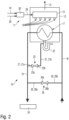
- shows a second water heater according to the present invention,
- Figure 3
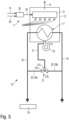
- shows a third water heater according to a comparative example,
- Figure 4
- shows a fourth water heater according to the present invention,
- Figure 5
- shows a fifth water heater according to the present invention.
-
Figures 1 and2 each show awater heater 10. - The
water heater 10 comprises agas burner 11 being configured to combust a gas if a heat demand is present, namely if heated water is requested by at least onewater consumer 24. - The gas burner comprises 11 a
burner chamber 12. Aburner rod 13 of thegas burner 11 is positioned within theburner chamber 11. -
Gas 14 is provided to theburner rod 13 for combusting thegas 14 within theburner chamber 12. Thegas 14 is preferably provided as a gas/air mixture 28. The combustion of thegas 14 of gas/air mixture 28 results intoflames 16 andexhaust gas 15. Theexhaust gas 15 emerges from theburner chamber 12 through a chimney. - As mentioned above, the
gas 14 is preferably provided as a gas/air mixture 28. Such a gas/air mixture 28 is usually provided by agas armature 30 of thegas burner 11.Such gas armatures 30 are well known. Such agas armature 30 usually comprises a fan (not shown) proving a flow ofair 29, a gas valve or gas modulator (not shown) providing a flow of thegas 14 and a mixing unit (not shown) mixing the air flow with the gas flow. The mixing ratio ofgas 14 andair 29 within the gas/air mixture 28 is usually kept at a defined value over the entire modulation rage of thegas burner 11 such that at any burner load of thegas burner 11 the mixing ratio of the gas/air mixture 28 is kept at the defined value. - The
water heater 10 further comprises aheat exchanger 17 being configured to heat water using the thermal energy provided with the combustion of thegas 14. Theheat exchanger 17 is positioned inside theburner chamber 12. Theheat exchanger 17 is a condensing heat exchanger. - The
water heater 10 further comprises aninput pipe 18 being configured to provide unheated water, namely water to be heated by theheat exchanger 17, to theheat exchanger 17. Thewater heater 10 further comprises anoutput pipe 19 being configured to provide water heated by theheat exchanger 17 to the at least onewater consumer 24. Thewater heater 10 further comprises a siphon ortrap 22 being configured to collect condensate resulting at the condensingheat exchanger 17 during operation of thewater heater 10. - The
water heater 10 further comprises a first connectingpipe 21 and avalve 23 acting together with thefirst connection pipe 21. Both thefirst connection pipe 21 and thevalve 23 are configured to guide water heated byheat exchanger 17 from theoutput pipe 19 to the siphon ortrap 22, and to guide water not heated by theheat exchanger 17 from theoutput pipe 19 to the siphon ortrap 22. - In
Figure 1 and2 , thefirst connection pipe 21 extends between theoutput pipe 19 and the siphon ortrap 22. Thevalve 23 acting together with thefirst connection pipe 21 is a 2-way valve positioned within thefirst connection pipe 21, wherein afirst port 23a of the 2-way-valve is connected to theoutput pipe 19 through a first section 21a of the first connectingpipe 21, and wherein asecond port 23b of the 2-way-valve is connected to the siphon ortrap 22 through a second section 21b of the first connectingpipe 21.Figure 2 according to a first embodiment of the invention shows a modification ofwater heater 10 ofFigure 1 . InFigure 2 thewater heater 10 comprises further a second connecting pipe 20 extending between theinput pipe 18 and theoutput pipe 19, and aseparate valve 26 acting together with the second connection pipe 20 being configured to guide water frominput pipe 18 to theoutput pipe 19. A first section 20a of the second connecting pipe 20 extends between theoutput pipe 19 and theseparate valve 26. A second section 20a of the second connecting pipe 20 extends between theinput pipe 18 and theseparate valve 26. All other details of the water heater ofFigure 2 are identical to the water heater ofFigure 1 . The second connecting pipe 20 may also be called bypass pipe. - If a heat demand is present at the
water heater 10 ofFigures 1 and2 , namely if heated water is requested by the at least onewater consumer 24, theinput pipe 18 provides water to theheat exchanger 17, said water becomes heated by theheat exchanger 17 when flowing through the same using the thermal energy resulting from the combustion of thegas 14 by thegas burner 11, and the water heated by theheat exchanger 17 is provided to therespective water consumer 24. In this situation thevalve 23 is closed. InFigure 2 thevalve 26 may be opened or closed in this situation. If thevalve 26 is closed in this situation, only water heated by theheat exchanger 17 is provided to therespective water consumer 24. If thevalve 26 is opened in this situation, the water heated by theheat exchanger 17 becomes mixed with unheated water bypassing theheat exchanger 17 and said mixture is provided to therespective water consumer 24. If a heat demand is not present at thewater heater 10 ofFigures 1 and2 , namely if heated water is not requested by the at least onewater consumer 24, thegas burner 11 may be active and may combustgas 14 or may inactive and may not combustgas 14. - If a heat demand is not present and if the
gas burner 11 of thewater heater 10 ofFigures 1 and2 is combustinggas 14, water heated by theheat exchanger 17 can be provided to the siphon ortrap 22 from theoutput pipe 19 through the first connectingpipe 21 and through thevalve 23. - If a heat demand is not present and if the
gas burner 11 of thewater heater 10 ofFigures 1 and2 is not combustinggas 14, water not being heated by theheat exchanger 17 but flowing through the same can be provided to the siphon ortrap 22 from theoutput pipe 19 through the first connectingpipe 21 and through thevalve 23. - So, heated water as well as unheated water can be provided to the siphon or
trap 22 without any water consumption at awater consumer 24. - If no heat demand is present, namely if heated water is not requested by the at least one
water consumer 24, for a calibration of thegas burner 11 of thewater heater 10 ofFigures 1 and2 , thewater heater 10 is operated as follows: Thegas burner 11 is operated at a defined calibration burner load for a defined calibration time interval and the water heated by theheat exchanger 17 during the calibration is provided by thevalve 23 to the siphon ortrap 22. During the calibration, the heated water is provided by thevalve 23 to the siphon ortrap 22 from theoutput pipe 19, namely in such a way that the heated water flows from theoutput pipe 19 through the first section 21a of the first connectingpipe 21, through thevalve 23 and through the second section 21b of the first connectingpipe 21 to the siphon ortrap 22. - If no heat demand is present, namely if heated water is not requested by the at least one
water consumer 24, for a filling the siphon ortrap 22 directly after installation of thewater heater 10 ofFigures 1 and2 , thewater heater 10 is operated as follows: Unheated water or heated water is provided by thevalve 23 to the siphon ortrap 22. Preferably, the unheated water or the heated water is provided by thevalve 23 to the siphon ortrap 22 from theoutput pipe 19. - To provide heated water to the siphon or
trap 22, thegas burner 11 is combustinggas 14 at a defined burner load. To provide unheated water to the siphon ortrap 22, thegas burner 11 is not combustinggas 14. The heated water or the unheated water is provided by thevalve 23 to the siphon ortrap 22 from theoutput pipe 19, namely in such a way that the water flows from theoutput pipe 19 through the first section 21a of the first connectingpipe 21, through thevalve 23 and through the second section 21b of the first connectingpipe 21 to the siphon ortrap 22. - If no heat demand is present, namely if heated water is not requested by the at least one
water consumer 24, for a cleaning the siphon ortrap 22 thewater heater 10 ofFigures 1 and2 is operated as follows: Unheated water or heated water is provided by thevalve 23 to the siphon ortrap 22. Unheated water or heated water is provided by thevalve 23 to the siphon ortrap 22. Preferably, the unheated water or the heated water is provided by thevalve 23 to the siphon ortrap 22 from theoutput pipe 19. - To provide heated water to the siphon or
trap 22, thegas burner 11 is combustinggas 14 at a defined burner load. To provide unheated water to the siphon ortrap 22, thegas burner 11 is not combustinggas 14. The heated water or the unheated water is provided by thevalve 23 to the siphon ortrap 22 from theoutput pipe 19, namely in such a way that the water flows from theoutput pipe 19 through the first section 21a of the first connectingpipe 21, through thevalve 23 and through the second section 21b of the first connectingpipe 21 to the siphon ortrap 22. - If no heat demand is present, namely if heated water is not requested by the at least one
water consumer 24, for a descaling of theheat exchanger 17 thewater heater 10 ofFigures 1 and2 is operated as follows. The following steps i) and ii) are alternately executed. Step i): Combust gas with thegas burner 11 at a defined burner load for a defined first time interval and provide the heated water to the siphon ortrap 22. Step ii): Stop combustion of gas within thegas burner 11 for a defined second time interval and provide the unheated water to the siphon ortrap 22. - If no heat demand is present, namely if heated water is not requested by the at least one
water consumer 24, for a descaling of theheat exchanger 17 thewater heater 10 ofFigures 1 and2 is alternatively operated as follows. The following steps i) and ii) are alternately executed. Step i): Combust gas with thegas burner 11 at a defined first burner load for a defined first time interval and provide the heated water to the siphon ortrap 22. Step ii) combust gas with thegas burner 11 at a defined second burner load for a defined second time interval and provide the heated water to the siphon ortrap 22, wherein the first burner load is relatively low compared to the second burner load. The first burner load may be a minimum burner load and the second burner load may be a maximum burner load. - For the descaling of the
heat exchanger 17 of thewater heater 10, during the first time interval and during the second time interval the water is provided from theoutput pipe 19 to the siphon ortrap 22 through thevalve 23, namely in such a way that the water flows from theoutput pipe 19 through the first section 21a of the first connectingpipe 21, through thevalve 23 and through the second section 21b of the first connectingpipe 21 to the siphon ortrap 22. - If in
Figures 1 and2 water flows fromoutput pipe 19 to the siphon ortrap 22, thevalve 23 is opened. -
Figures 3 and4 both show awater heater 10. The comparative water heater ofFigure 3 differs from the comparative water heater ofFigure 1 and the water heater ofFigure 4 according to a second embodiment of the invention differs from the water heater ofFigure 2 according the first embodiment of the invention merely by the design of therespective valve first connection pipe 21. While inFigures 1 and2 saidvalve 23 is provided by a 2-way-valve, inFigures 3 and4 saidvalve 25 is provided by a 3-way-valve. InFigures 3 and4 , afirst port 25a of the 3-way-valve is connected to theheat exchanger 17 through a first section 19a of theoutput pipe 19, wherein asecond port 25b of the 3-way-valve is connected to the at least onewater consumer 24 through a second section 19b of theoutput pipe 19, and wherein athird port 25c of the 3-way-valve is connected to the siphon ortrap 22 through the first connectingpipe 21. -
Figure 4 differs fromFigure 3 merely by the second connecting pipe 20 extending between theinput pipe 18 and theoutput pipe 19, and by theseparate valve 26 acting together with second connection pipe 20 being configured to guide water frominput pipe 18 to theoutput pipe 19. - In
Figures 3 and4 as well as inFigures 1 and2 both thefirst connection pipe 21 and therespective valve heat exchanger 17 from theoutput pipe 19 to the siphon ortrap 22, and to guide water not heated by theheat exchanger 17 from theoutput pipe 19 to the siphon ortrap 22. The second connecting pipe 20 may also be called bypass pipe. - If a heat demand is present at the
water heater 10 ofFigures 3 and4 , namely if heated water is requested by the at least onewater consumer 24, theinput pipe 18 provides water to theheat exchanger 17, said water becomes heated by theheat exchanger 17 when flowing through the same using the thermal energy resulting from the combustion of thegas 14 by thegas burner 11, and the water heated by theheat exchanger 17 is provided to therespective water consumer 24. In this situation theports valve 25 are opened and theport 25c of thevalve 25 is closed. InFigure 4 thevalve 26 may be opened or closed in this situation. If thevalve 26 is closed in this situation, only water heated by theheat exchanger 17 is provided to therespective water consumer 24. If thevalve 26 is opened in this situation, the water heated by theheat exchanger 17 becomes mixed with unheated water bypassing theheat exchanger 17 and said mixture is provided to therespective water consumer 24. If a heat demand is not present at thewater heater 10 ofFigures 3 and4 , namely if heated water is not requested by the at least onewater consumer 24, thegas burner 11 may be active and may combustgas 14 or may inactive and may not combustgas 14. - If a heat demand is not present and if the
gas burner 11 of thewater heater 10 ofFigures 3 and4 is combustinggas 14, water heated by theheat exchanger 17 can be provided to the siphon ortrap 22 from theoutput pipe 19 through the first connectingpipe 21 and through thevalve 25. - If a heat demand is not present and if the
gas burner 11 of thewater heater 10 ofFigures 3 and4 is not combustinggas 14, water not being heated by theheat exchanger 17 but flowing through the same can be provided to the siphon ortrap 22 from theoutput pipe 19 through the first connectingpipe 21 and through thevalve 25. So, heated water as well as unheated water can be provided to the siphon ortrap 22 without any water consumption at awater consumer 24. - If no heat demand is present, namely if heated water is not requested by the at least one
water consumer 24, for a calibration of thegas burner 11 of thewater heater 10 ofFigures 3 and4 , thewater heater 10 is operated as follows: Thegas burner 11 is operated at a defined calibration burner load for a defined calibration time interval and the water heated by theheat exchanger 17 during the calibration is provided by thevalve 25 to the siphon ortrap 22. In this situation theports valve 25 are opened and theport 25b of thevalve 25 is closed. During the calibration, the heated water is provided by thevalve 25 to the siphon ortrap 22 from theoutput pipe 19, namely in such a way that the heated water flows from the first section 19a of theoutput pipe 19 through thevalve 25 and through the first connectingpipe 21 to the siphon ortrap 22. - If no heat demand is present, namely if heated water is not requested by the at least one
water consumer 24, for a filling the siphon ortrap 22 directly after installation of thewater heater 10 ofFigures 3 and4 , thewater heater 10 is operated as follows: Unheated water or heated water is provided by thevalve 25 to the siphon ortrap 22. Preferably, the unheated water or the heated water is provided by thevalve 25 to the siphon ortrap 22 from theoutput pipe 19. To provide heated water to the siphon ortrap 22, thegas burner 11 is combustinggas 14 at a defined burner load. To provide unheated water to the siphon ortrap 22, thegas burner 11 is not combustinggas 14. The heated water or the unheated water is provided by thevalve 25 to the siphon ortrap 22 from theoutput pipe 19, namely in such a way that the water flows from the first section 19a of theoutput pipe 19 through thevalve 25 and through the first connectingpipe 21 to the siphon ortrap 22. - If no heat demand is present, namely if heated water is not requested by the at least one
water consumer 24, for a cleaning the siphon ortrap 22 thewater heater 10 ofFigures 3 and4 is operated as follows: Unheated water or heated water is provided by thevalve 25 to the siphon ortrap 22. Unheated water or heated water is provided by thevalve 25 to the siphon ortrap 22. Preferably, the unheated water or the heated water is provided by thevalve 25 to the siphon ortrap 22 from theoutput pipe 19. To provide heated water to the siphon ortrap 22, thegas burner 11 is combustinggas 14 at a defined burner load. To provide unheated water to the siphon ortrap 22, thegas burner 11 is not combustinggas 14. The heated water or the unheated water is provided by thevalve 25 to the siphon ortrap 22 from theoutput pipe 19, namely in such a way that the water flows from the first section 19a of theoutput pipe 19 through thevalve 25 and through the first connectingpipe 21 to the siphon ortrap 22. - If no heat demand is present, namely if heated water is not requested by the at least one
water consumer 24, for a descaling of theheat exchanger 17 thewater heater 10 ofFigures 3 and4 is operated as follows. The following steps i) and ii) are alternately executed. Step i): Combust gas with thegas burner 11 at a defined burner load for a defined first time interval and provide the heated water to the siphon ortrap 22. Step ii): Stop combustion of gas within thegas burner 11 for a defined second time interval and provide the unheated water to the siphon ortrap 22. - If no heat demand is present, namely if heated water is not requested by the at least one
water consumer 24, for a descaling of theheat exchanger 17 thewater heater 10 ofFigures 3 and4 is alternatively operated as follows. The following steps i) and ii) are alternately executed. Step i): Combust gas with thegas burner 11 at a defined first burner load for a defined first time interval and provide the heated water to the siphon ortrap 22. Step ii) combust gas with thegas burner 11 at a defined second burner load for a defined second time interval and provide the heated water to the siphon ortrap 22, wherein the first burner load is relatively low compared to the second burner load. The first burner load may be a minimum burner load and the second burner load may be a maximum burner load. - For the descaling of the
heat exchanger 17 of thewater heater 10, during the first time interval and during the second time interval the water is provided from theoutput pipe 19 to the siphon ortrap 22 through thevalve 25, namely in such a way that the water flows from the first section 19a of theoutput pipe 19 through thevalve 25 and through the first connectingpipe 21 to the siphon ortrap 22. - If in
Figures 3 and4 water flows fromoutput pipe 19 to the siphon ortrap 22, theports valve 25 are opened and theport 25b of thevalve 25 is closed. -
Figures 5 both shows awater heater 10 according to a third embodiment of the present invention. - The
water heater 10 ofFigure 5 mandatorily comprises the second connecting pipe 20 extending between theinput pipe 18 and theoutput pipe 19. The second connecting pipe 20 may also be called bypass pipe. InFigure 5 , the first connectingpipe 21 extends between the second connecting pipe 20 and the siphon ortrap 22. The water heater ofFigure 5 further comprises avalve 27 connected between the first connectingpipe 21 and the second connectingpipe 22. Saidvalve 27 is configured to guide water heated byheat exchanger 17 from theoutput pipe 19 to the siphon ortrap 22, and to guide water unheated by theheat exchanger 17 but flowing through the same from theoutput pipe 19 to the siphon ortrap 22. This can be done even if no heat demand is present, namely if heated water is not requested by the at least onewater consumer 24. Saidvalve 27 is also configured to guide unheated water bypassing theheat exchanger 18 from theinput pipe 18 to the siphon ortrap 22. - The
valve 27 ofFigure 5 is a 3-way-valve. Afirst port 27a of the 3-way-valve 27 is connected tooutput pipe 19 through a first section 20a of the second connecting pipe 20. Asecond port 27b of the 3-way-valve 27 is connected to inputpipe 18 through a second section 20b of the second connecting pipe 20. A third port 27c of the 3-way-valve 27 is connected to the siphon ortrap 22 through the first connectingpipe 21. - If a heat demand is present at the water heater of
Figure 5 , namely if heated water is requested by the at least onewater consumer 24, theinput pipe 18 provides water to theheat exchanger 17, said water becomes heated by theheat exchanger 17 when flowing through the same using the thermal energy resulting from the combustion of thegas 14 by thegas burner 11, and the water heated by theheat exchanger 17 is provided to therespective water consumer 24. In this situation thevalve 27 may be closed or opened. - If the
valve 27 is closed in this situation, only water heated by theheat exchanger 17 is provided to therespective water consumer 24. If thevalve 27 is opened in this situation, the water heated by theheat exchanger 17 becomes mixed with unheated water bypassing the heat exchanger and said mixture is provided to therespective water consumer 24. - If a heat demand is not present at the water heater of
Figure 5 , namely if heated water is not requested by the at least onewater consumer 24, thegas burner 11 may be active and may combustgas 14 or may inactive and may not combustgas 14. - If a heat demand is not present and if the
gas burner 11 of the water heater ofFigure 5 is combustinggas 14, water heated by theheat exchanger 17 can be provided to the siphon ortrap 22 from theoutput pipe 19 through the first section 20a of first connecting pipe 20, through the 3-way valve 27 and through the second connectingpipe 21. - If a heat demand is not present and if the
gas burner 11 of the water heater ofFigure 5 is not combustinggas 14, water not being heated by theheat exchanger 17 but flowing through the same can be provided to the siphon ortrap 22 from theoutput pipe 19 through the first section 20a of first connecting pipe 20, through the 3-way valve 27 and through the second connectingpipe 21. - So, heated water as well as unheated water can be provided to the siphon or
trap 22 without any water consumption at awater consumer 24. - If no heat demand is present, namely if heated water is not requested by the at least one
water consumer 24, for a calibration of thegas burner 11 of thewater heater 10 ofFigure 5 thewater heater 10 is operated as follows: Thegas burner 11 is operated at a defined calibration burner load for a defined calibration time interval and the water heated by theheat exchanger 17 during the calibration is provided by thevalve 27 to the siphon ortrap 22. During the calibration, the heated water is provided by thevalve 27 to the siphon ortrap 22 from theoutput pipe 19, namely in such a way that the heater water flows from theoutput pipe 19 through the first section 20a of the first connecting pipe 20, through thevalve 27 and through thesecond connection pipe 21 to the siphon ortrap 22. - If no heat demand is present, namely if heated water is not requested by the at least one
water consumer 24, for a filling the siphon ortrap 22 directly after installation of thewater heater 10 ofFigure 5 , thewater heater 10 is operated as follows: Unheated water or heated water is provided by thevalve 27 to the siphon ortrap 22. Preferably, the unheated water or the heated water is provided by thevalve 27 to the siphon ortrap 22 from theoutput pipe 19. To provide heated water to the siphon ortrap 22, thegas burner 11 is combustinggas 14 at a defined burner load. To provide unheated water to the siphon ortrap 22, thegas burner 11 is not combustinggas 14. The heated water or the unheated water is provided by thevalve 27 to the siphon ortrap 22 from theoutput pipe 19, namely in such a way that the water flows from theoutput pipe 19 through the first section 20a of the first connecting pipe 20, through thevalve 27 and through thesecond connection pipe 21 to the siphon ortrap 22. - If no heat demand is present, namely if heated water is not requested by the at least one
water consumer 24, for a cleaning the siphon ortrap 22 thewater heater 10 ofFigure 5 is operated as follows: Unheated water or heated water is provided by the valve to the siphon ortrap 22. Unheated water or heated water is provided by thevalve 27 to the siphon ortrap 22. Preferably, the unheated water or the heated water is provided by thevalve 27 to the siphon ortrap 22 from theoutput pipe 19. To provide heated water to the siphon ortrap 22, thegas burner 11 is combustinggas 14 at a defined burner load. To provide unheated water to the siphon ortrap 22, thegas burner 11 is not combustinggas 14. The heated water or the unheated water is provided by thevalve 27 to the siphon ortrap 22 from theoutput pipe 19, namely in such a way that the water flows from theoutput pipe 19 through the first section 20a of the first connecting pipe 20, through thevalve 27 and through thesecond connection pipe 21 to the siphon ortrap 22. - If no heat demand is present, namely if heated water is not requested by the at least one
water consumer 24, for a descaling of theheat exchanger 17 thewater heater 10 ofFigure 5 is operated as follows. The following steps i) and ii) are alternately executed. Step i): Combust gas with thegas burner 11 at a defined burner load for a defined first time interval and provide the heated water to the siphon ortrap 22. Step ii): Stop combustion of gas within thegas burner 11 for a defined second time interval and provide the unheated water to the siphon ortrap 22. - If no heat demand is present, namely if heated water is not re-quested by the at least one
water consumer 24, for a descaling of theheat exchanger 17 thewater heater 10 ofFigure 5 is alternatively operated as follows. The following steps i) and ii) are alternately executed. Step i): Combust gas with thegas burner 11 at a defined first burner load for a defined first time interval and provide the heated water to the siphon ortrap 22. Step ii) combust gas with thegas burner 11 at a defined second burner load for a defined second time interval and provide the heated water to the siphon ortrap 22, wherein the first burner load is relatively low compared to the second burner load. The first burner load may be a minimum burner load and the second burner load may be a maximum burner load. - For the descaling of the
heat exchanger 17 of thewater heater 10 ofFigure 5 , during the first time interval and during the second time interval the water is provided from theoutput pipe 19 to the siphon ortrap 22 through thevalve 27, namely in such a way that the water flows from theoutput pipe 19 through the first section 20a of the first connecting pipe 20, through thevalve 27 and through thesecond connection pipe 21 to the siphon ortrap 22. - If in
Figure 5 water flows fromoutput pipe 19 through the first section 20a of the first connecting pipe 20, through thevalve 27 and through thesecond connection pipe 21 to the siphon ortrap 22, thevalve 27 is in a status in which thefirst valve port 27a and third valve port valve 27c are unblocked or opened while thesecond valve port 27b is blocked or closed. -
- 10
- water heater
- 11
- gas burner
- 12
- combustion camber
- 13
- burner rod
- 14
- gas or gas/air mixture
- 15
- exhaust gas
- 16
- flame
- 17
- heat exchanger
- 18
- input pipe
- 19
- output pipe
- 19a
- first section
- 19b
- second section
- 20
- connecting pipe
- 20a
- first section
- 20b
- second section
- 21
- connecting pipe
- 21a
- first section
- 21b
- second section
- 22
- siphon or trap
- 23
- valve
- 23a
- first valve port
- 23b
- second valve port
- 24
- water consumer
- 25
- valve
- 25a
- first valve port
- 25b
- second valve port
- 25c
- third valve port
- 26
- valve
- 26a
- first valve port
- 26b
- second valve port
- 27
- valve
- 27a
- first valve port
- 27b
- second valve port
- 27c
- third valve port
- 28
- gas/air mixture
- 29
- air
- 30
- gas armature
Claims (13)
- Water heater (10) comprising:a gas burner (11) being configured to combust gas if a heat demand is present, namely if heated water is requested by at least one water consumer (24),a heat exchanger (17) being configured to heat water using the thermal energy provided with the combustion of the gas, wherein the heat exchanger (17) is a condensing heat exchanger,an input pipe (18) being configured to provide water to be heated to the heat exchanger (17),an output pipe (19) being configured to provide water heated by the heat exchanger (17) to the at least one water consumer (24),a siphon or trap (22) being configured to collect condensate resulting at the condensing heat exchanger (17) during operation of the water heater (10),a first connection pipe (21) and a valve (23, 25, 27) acting together with the first connection pipe (21), both the first connection pipe (21) and the valve (23, 25, 27) being configured toguide water heated by heat exchanger (17) from the output pipe (19) to the siphon or trap (22), and/orguide water not heated by the heat exchanger (17) from the output pipe (19) to the siphon or trap (22),characterized bya second connecting pipe (20) extending between the input pipe (18) and the output pipe (19),wherein in a first alternative a separate valve (26) acts together with the second connection pipe (20) being configured to guide water from input pipe (18) to the output pipe (19), orwherein in a second alternative the first connecting pipe (21) extends between the second connecting pipe (20) and the siphon or trap (22), the valve (27) acting together with the first connection pipe (21) is provided by a 3-way-valve, is connected between the first connecting pipe (21) and the second connecting pipe (20) and acts also together with the second connection pipe (20), a first port (27a) of the 3-way-valve is connected to the output pipe (19) through a first section (20a) of the second connecting pipe (20), a second port (27b) of the 3-way-valve is connected to the input pipe (18) through a second section (10b) of the second connecting pipe (20), and a third port (27c) of the 3-way-valve is connected to the siphon or trap (22) through the first connecting pipe (21).
- Water heater (10) of claim 1, characterized in that
in the first alternative the valve (23) acting together with first connection pipe (21) is a 2-way valve positioned within the first connection pipe (21),wherein a first port (23a) of the 2-way-valve is connected to the output pipe (19) through a first section (21a) of the first connecting pipe (21),wherein a second port (23b) of the 2-way-valve is connected to the siphon or trap (22) through a second section (21b) of the first connecting pipe (21). - Water heater (10) of claim 1, characterized in that
in the first alternative the valve (25) acting together with first connection pipe (21) is a 3-way valve,wherein a first port (25a) of the 3-way-valve is connected to the heat exchanger (17) through a first section (19a) of the output pipe (19),wherein a second port (25b) of the 3-way-valve is connected to the at least one water consumer (24) through a second section (19b) of the output pipe (19),wherein a third port (25c) of the 3-way-valve is connected to the siphon or trap (22) through the first connecting pipe (21). - Water heater of one of claims 1 to 3, characterized in thatthe gas burner (11) comprises a burner chamber (12),the heat exchanger (17) is positioned inside the burner chamber (12) of the gas burner (11),the siphon or trap (22) is positioned outside of the burner chamber (12) of the gas burner (11).
- Method to operate the water heater of one of claims 1 to 4, characterized in that
if no heat demand is present, namely if heated water is not requested by the at least one water consumer (24), for a calibration of the gas burner (11) of the water heater (10) the gas burner (11) is operated at a defined burner load for a defined time interval and the water heated by the heat exchanger (17) during the calibration is provided to the siphon or trap (22). - Method of claim 5, characterized in that
the water heated during the calibration is provided from the output pipe (19) to the siphon or trap (22) through the valve (23, 25, 27). - Method to operate the water heater of one of claims 1 to 4, preferably according to claim 5 or 6, characterized in that
if no heat demand is present, namely if heated water is not requested by the at least one water consumer (24), for a filling of the siphon or trap (22) directly after installation of the water heater (10) unheated water or heated water is provided to the siphon or trap (22). - Method of claim 7, characterized in that
the unheated water or the heated water is provided from the output pipe (19) to the siphon or trap (22) through the valve (23, 25, 27). - Method to operate the water heater of one of claims 1 to 6, preferably according to one of claims 5 to 8, characterized in that
if no heat demand is present, namely if heated water is not requested by the at least one water consumer (24), for a cleaning of the siphon or trap (22) unheated water or heated water is provided to the siphon or trap (22). - Method of claim 9, characterized in that
the unheated water or the heated water is provided from the output pipe (19) to the siphon or trap (22) through the valve (23, 25, 27). - Method to operate the water heater of one of claims 1 to 4, preferably according to one of claims 5 to 10, characterized in that
if no heat demand is present, namely if heated water is not requested by the at least one water consumer (24), for a descaling of the heat exchanger (17) the following steps are alternately executed:i) combust gas with the gas burner (11) at a defined burner load for a defined first time interval and provide the heated water to the siphon or trap (22),ii) stop combustion of gas within the gas burner (11) for a defined second time interval and provide the unheated water to the siphon or trap (22). - Method to operate the water heater of one of claims 1 to 4, preferably according to one of claims 5 to 10, characterized in that
if no heat demand is present, namely if heated water is not requested by the at least one water consumer (24), for a descaling of the heat exchanger (17) the following steps are alternately executed:i) combust gas with the gas burner (11) at a defined first burner load, preferably at a minimum burner load, for a defined first time interval and provide the heated water to the siphon or trap (22),ii) combust gas with the gas burner (11) at a defined second burner load, preferably at a maximum burner load, for a defined second time interval and provide the heated water to the siphon or trap (22), wherein the first burner load is relatively low compared to the second burner load. - Method of claim 11 or 12, characterized in that
the during the first time interval and during the second time interval the water is provided from the output pipe (19) to the siphon or trap (22) through the valve (23).
Priority Applications (3)
| Application Number | Priority Date | Filing Date | Title |
|---|---|---|---|
| EP21198629.4A EP4155620B1 (en) | 2021-09-23 | 2021-09-23 | Water heater and methods to operate a water heater |
| US18/694,082 US20240393014A1 (en) | 2021-09-23 | 2022-09-07 | Water heater and methods to operate a water heater |
| PCT/EP2022/074784 WO2023046467A1 (en) | 2021-09-23 | 2022-09-07 | Water heater and methods to operate a water heater |
Applications Claiming Priority (1)
| Application Number | Priority Date | Filing Date | Title |
|---|---|---|---|
| EP21198629.4A EP4155620B1 (en) | 2021-09-23 | 2021-09-23 | Water heater and methods to operate a water heater |
Publications (2)
| Publication Number | Publication Date |
|---|---|
| EP4155620A1 EP4155620A1 (en) | 2023-03-29 |
| EP4155620B1 true EP4155620B1 (en) | 2025-01-08 |
Family
ID=77913018
Family Applications (1)
| Application Number | Title | Priority Date | Filing Date |
|---|---|---|---|
| EP21198629.4A Active EP4155620B1 (en) | 2021-09-23 | 2021-09-23 | Water heater and methods to operate a water heater |
Country Status (3)
| Country | Link |
|---|---|
| US (1) | US20240393014A1 (en) |
| EP (1) | EP4155620B1 (en) |
| WO (1) | WO2023046467A1 (en) |
Family Cites Families (7)
| Publication number | Priority date | Publication date | Assignee | Title |
|---|---|---|---|---|
| KR910000677B1 (en) | 1985-07-15 | 1991-01-31 | 도오도오 기기 가부시기가이샤 | Multiple-purpose instantaneous gas water heater |
| CH685067A5 (en) * | 1990-10-19 | 1995-03-15 | Vaillant Gmbh | Heater. |
| AT394769B (en) * | 1990-11-26 | 1992-06-25 | Vaillant Gmbh | Heating appliance with burner |
| EP1063481B1 (en) | 1999-06-25 | 2006-01-18 | Vaillant GmbH | Gas fired instantaneous water heater |
| DE102006059582B3 (en) * | 2006-12-16 | 2008-03-27 | Robert Bosch Gmbh | Siphon freeze protection device for condensing heating device, has heating unit provided for heating siphon to prevent freezing of condensation water and/or sealing liquid and formed as condensing heating device-internal heating unit |
| US7298968B1 (en) | 2007-01-05 | 2007-11-20 | Rheem Manufacturing Company | Pumpless combination instantaneous/storage water heater system |
| CA3013142A1 (en) | 2017-08-03 | 2019-02-03 | Rheem Manufacturing Company | Water heater with flow bypass |
-
2021
- 2021-09-23 EP EP21198629.4A patent/EP4155620B1/en active Active
-
2022
- 2022-09-07 WO PCT/EP2022/074784 patent/WO2023046467A1/en not_active Ceased
- 2022-09-07 US US18/694,082 patent/US20240393014A1/en active Pending
Also Published As
| Publication number | Publication date |
|---|---|
| WO2023046467A1 (en) | 2023-03-30 |
| EP4155620A1 (en) | 2023-03-29 |
| US20240393014A1 (en) | 2024-11-28 |
Similar Documents
| Publication | Publication Date | Title |
|---|---|---|
| AU2011339872B2 (en) | Heating and method for controlling a heating | |
| US6283115B1 (en) | Modulating furnace having improved low stage characteristics | |
| CN110455078B (en) | A pulse heating furnace control method | |
| US6321744B1 (en) | Modulating furnace having a low stage with an improved fuel utilization efficiency | |
| CN112833555B (en) | Gas water heater and control method thereof | |
| AU2007237285A1 (en) | Four-stage high efficiency furnace | |
| US20080127962A1 (en) | Pressure switch assembly for a furnace | |
| EP4155620A1 (en) | Water heater and methods to operate a water heater | |
| EP4219986A1 (en) | 3-way fluid valve, appliance for handling a fluid flow having a 3-way fluid valve and water heater having a 3-way fluid valve and methods to operate the same | |
| JP2007155163A (en) | Combined heat source machine | |
| CN210624950U (en) | Gas water heater | |
| CA2677549C (en) | Thermal switch for energy sustaining water heater | |
| CN214949847U (en) | High-load regulation ratio gas heating water heater | |
| CN211503218U (en) | Heating system | |
| CN110793186B (en) | Heating system and control method thereof | |
| CN110793185A (en) | Gas water heating system and control method thereof | |
| CN211503219U (en) | Gas water heating system | |
| CN211400281U (en) | Wall-mounted furnace | |
| JPH0422209Y2 (en) | ||
| DE102007029971B4 (en) | Method for operating a heater | |
| CN112212511A (en) | High-load regulation ratio gas heating water heater | |
| CN216432106U (en) | Three-return-stroke low-nitrogen vacuum boiler | |
| CN222911389U (en) | A booster frequency conversion water servo water inlet valve and gas heating hot water boiler | |
| KR100291490B1 (en) | Control method of rapid operation of gas boiler | |
| CN211503221U (en) | Zero-cold water gas water heater |
Legal Events
| Date | Code | Title | Description |
|---|---|---|---|
| PUAI | Public reference made under article 153(3) epc to a published international application that has entered the european phase |
Free format text: ORIGINAL CODE: 0009012 |
|
| STAA | Information on the status of an ep patent application or granted ep patent |
Free format text: STATUS: THE APPLICATION HAS BEEN PUBLISHED |
|
| AK | Designated contracting states |
Kind code of ref document: A1 Designated state(s): AL AT BE BG CH CY CZ DE DK EE ES FI FR GB GR HR HU IE IS IT LI LT LU LV MC MK MT NL NO PL PT RO RS SE SI SK SM TR |
|
| STAA | Information on the status of an ep patent application or granted ep patent |
Free format text: STATUS: REQUEST FOR EXAMINATION WAS MADE |
|
| P01 | Opt-out of the competence of the unified patent court (upc) registered |
Effective date: 20230827 |
|
| RIN1 | Information on inventor provided before grant (corrected) |
Inventor name: STURM, CHRISTOPH Inventor name: DEPTOLLA, UWE |
|
| 17P | Request for examination filed |
Effective date: 20230925 |
|
| RBV | Designated contracting states (corrected) |
Designated state(s): AL AT BE BG CH CY CZ DE DK EE ES FI FR GB GR HR HU IE IS IT LI LT LU LV MC MK MT NL NO PL PT RO RS SE SI SK SM TR |
|
| GRAP | Despatch of communication of intention to grant a patent |
Free format text: ORIGINAL CODE: EPIDOSNIGR1 |
|
| STAA | Information on the status of an ep patent application or granted ep patent |
Free format text: STATUS: GRANT OF PATENT IS INTENDED |
|
| RIC1 | Information provided on ipc code assigned before grant |
Ipc: F24D 19/00 20060101ALI20240709BHEP Ipc: F24H 15/31 20220101ALI20240709BHEP Ipc: F24H 1/52 20220101ALI20240709BHEP Ipc: F24H 9/20 20220101ALI20240709BHEP Ipc: F24H 8/00 20220101AFI20240709BHEP |
|
| INTG | Intention to grant announced |
Effective date: 20240723 |
|
| RIN1 | Information on inventor provided before grant (corrected) |
Inventor name: DEPTOLLA, UWE Inventor name: STURM, CHRISTOPH |
|
| RIN1 | Information on inventor provided before grant (corrected) |
Inventor name: MICHALEK, DUSAN Inventor name: DEPTOLLA, UWE |
|
| GRAS | Grant fee paid |
Free format text: ORIGINAL CODE: EPIDOSNIGR3 |
|
| GRAJ | Information related to disapproval of communication of intention to grant by the applicant or resumption of examination proceedings by the epo deleted |
Free format text: ORIGINAL CODE: EPIDOSDIGR1 |
|
| GRAL | Information related to payment of fee for publishing/printing deleted |
Free format text: ORIGINAL CODE: EPIDOSDIGR3 |
|
| STAA | Information on the status of an ep patent application or granted ep patent |
Free format text: STATUS: REQUEST FOR EXAMINATION WAS MADE |
|
| GRAP | Despatch of communication of intention to grant a patent |
Free format text: ORIGINAL CODE: EPIDOSNIGR1 |
|
| STAA | Information on the status of an ep patent application or granted ep patent |
Free format text: STATUS: GRANT OF PATENT IS INTENDED |
|
| GRAA | (expected) grant |
Free format text: ORIGINAL CODE: 0009210 |
|
| STAA | Information on the status of an ep patent application or granted ep patent |
Free format text: STATUS: THE PATENT HAS BEEN GRANTED |
|
| INTC | Intention to grant announced (deleted) | ||
| INTG | Intention to grant announced |
Effective date: 20241121 |
|
| AK | Designated contracting states |
Kind code of ref document: B1 Designated state(s): AL AT BE BG CH CY CZ DE DK EE ES FI FR GB GR HR HU IE IS IT LI LT LU LV MC MK MT NL NO PL PT RO RS SE SI SK SM TR |
|
| REG | Reference to a national code |
Ref country code: GB Ref legal event code: FG4D |
|
| REG | Reference to a national code |
Ref country code: CH Ref legal event code: EP |
|
| REG | Reference to a national code |
Ref country code: DE Ref legal event code: R096 Ref document number: 602021024599 Country of ref document: DE |
|
| REG | Reference to a national code |
Ref country code: IE Ref legal event code: FG4D |
|
| REG | Reference to a national code |
Ref country code: LT Ref legal event code: MG9D |
|
| REG | Reference to a national code |
Ref country code: NL Ref legal event code: MP Effective date: 20250108 |
|
| REG | Reference to a national code |
Ref country code: AT Ref legal event code: MK05 Ref document number: 1758560 Country of ref document: AT Kind code of ref document: T Effective date: 20250108 |
|
| PG25 | Lapsed in a contracting state [announced via postgrant information from national office to epo] |
Ref country code: NL Free format text: LAPSE BECAUSE OF FAILURE TO SUBMIT A TRANSLATION OF THE DESCRIPTION OR TO PAY THE FEE WITHIN THE PRESCRIBED TIME-LIMIT Effective date: 20250108 |
|
| PG25 | Lapsed in a contracting state [announced via postgrant information from national office to epo] |
Ref country code: RS Free format text: LAPSE BECAUSE OF FAILURE TO SUBMIT A TRANSLATION OF THE DESCRIPTION OR TO PAY THE FEE WITHIN THE PRESCRIBED TIME-LIMIT Effective date: 20250408 |
|
| PG25 | Lapsed in a contracting state [announced via postgrant information from national office to epo] |
Ref country code: FI Free format text: LAPSE BECAUSE OF FAILURE TO SUBMIT A TRANSLATION OF THE DESCRIPTION OR TO PAY THE FEE WITHIN THE PRESCRIBED TIME-LIMIT Effective date: 20250108 |
|
| PG25 | Lapsed in a contracting state [announced via postgrant information from national office to epo] |
Ref country code: PL Free format text: LAPSE BECAUSE OF FAILURE TO SUBMIT A TRANSLATION OF THE DESCRIPTION OR TO PAY THE FEE WITHIN THE PRESCRIBED TIME-LIMIT Effective date: 20250108 |
|
| PG25 | Lapsed in a contracting state [announced via postgrant information from national office to epo] |
Ref country code: ES Free format text: LAPSE BECAUSE OF FAILURE TO SUBMIT A TRANSLATION OF THE DESCRIPTION OR TO PAY THE FEE WITHIN THE PRESCRIBED TIME-LIMIT Effective date: 20250108 |
|
| PG25 | Lapsed in a contracting state [announced via postgrant information from national office to epo] |
Ref country code: NO Free format text: LAPSE BECAUSE OF FAILURE TO SUBMIT A TRANSLATION OF THE DESCRIPTION OR TO PAY THE FEE WITHIN THE PRESCRIBED TIME-LIMIT Effective date: 20250408 Ref country code: IS Free format text: LAPSE BECAUSE OF FAILURE TO SUBMIT A TRANSLATION OF THE DESCRIPTION OR TO PAY THE FEE WITHIN THE PRESCRIBED TIME-LIMIT Effective date: 20250508 |
|
| PG25 | Lapsed in a contracting state [announced via postgrant information from national office to epo] |
Ref country code: HR Free format text: LAPSE BECAUSE OF FAILURE TO SUBMIT A TRANSLATION OF THE DESCRIPTION OR TO PAY THE FEE WITHIN THE PRESCRIBED TIME-LIMIT Effective date: 20250108 |
|
| PG25 | Lapsed in a contracting state [announced via postgrant information from national office to epo] |
Ref country code: LV Free format text: LAPSE BECAUSE OF FAILURE TO SUBMIT A TRANSLATION OF THE DESCRIPTION OR TO PAY THE FEE WITHIN THE PRESCRIBED TIME-LIMIT Effective date: 20250108 Ref country code: PT Free format text: LAPSE BECAUSE OF FAILURE TO SUBMIT A TRANSLATION OF THE DESCRIPTION OR TO PAY THE FEE WITHIN THE PRESCRIBED TIME-LIMIT Effective date: 20250508 |
|
| PG25 | Lapsed in a contracting state [announced via postgrant information from national office to epo] |
Ref country code: BG Free format text: LAPSE BECAUSE OF FAILURE TO SUBMIT A TRANSLATION OF THE DESCRIPTION OR TO PAY THE FEE WITHIN THE PRESCRIBED TIME-LIMIT Effective date: 20250108 Ref country code: GR Free format text: LAPSE BECAUSE OF FAILURE TO SUBMIT A TRANSLATION OF THE DESCRIPTION OR TO PAY THE FEE WITHIN THE PRESCRIBED TIME-LIMIT Effective date: 20250409 |
|
| PG25 | Lapsed in a contracting state [announced via postgrant information from national office to epo] |
Ref country code: AT Free format text: LAPSE BECAUSE OF FAILURE TO SUBMIT A TRANSLATION OF THE DESCRIPTION OR TO PAY THE FEE WITHIN THE PRESCRIBED TIME-LIMIT Effective date: 20250108 |
|
| PG25 | Lapsed in a contracting state [announced via postgrant information from national office to epo] |
Ref country code: SE Free format text: LAPSE BECAUSE OF FAILURE TO SUBMIT A TRANSLATION OF THE DESCRIPTION OR TO PAY THE FEE WITHIN THE PRESCRIBED TIME-LIMIT Effective date: 20250108 |
|
| PG25 | Lapsed in a contracting state [announced via postgrant information from national office to epo] |
Ref country code: SM Free format text: LAPSE BECAUSE OF FAILURE TO SUBMIT A TRANSLATION OF THE DESCRIPTION OR TO PAY THE FEE WITHIN THE PRESCRIBED TIME-LIMIT Effective date: 20250108 |
|
| REG | Reference to a national code |
Ref country code: DE Ref legal event code: R097 Ref document number: 602021024599 Country of ref document: DE |
|
| PG25 | Lapsed in a contracting state [announced via postgrant information from national office to epo] |
Ref country code: DK Free format text: LAPSE BECAUSE OF FAILURE TO SUBMIT A TRANSLATION OF THE DESCRIPTION OR TO PAY THE FEE WITHIN THE PRESCRIBED TIME-LIMIT Effective date: 20250108 |
|
| PG25 | Lapsed in a contracting state [announced via postgrant information from national office to epo] |
Ref country code: CZ Free format text: LAPSE BECAUSE OF FAILURE TO SUBMIT A TRANSLATION OF THE DESCRIPTION OR TO PAY THE FEE WITHIN THE PRESCRIBED TIME-LIMIT Effective date: 20250108 Ref country code: EE Free format text: LAPSE BECAUSE OF FAILURE TO SUBMIT A TRANSLATION OF THE DESCRIPTION OR TO PAY THE FEE WITHIN THE PRESCRIBED TIME-LIMIT Effective date: 20250108 |
|
| PG25 | Lapsed in a contracting state [announced via postgrant information from national office to epo] |
Ref country code: RO Free format text: LAPSE BECAUSE OF FAILURE TO SUBMIT A TRANSLATION OF THE DESCRIPTION OR TO PAY THE FEE WITHIN THE PRESCRIBED TIME-LIMIT Effective date: 20250108 |
|
| PG25 | Lapsed in a contracting state [announced via postgrant information from national office to epo] |
Ref country code: SK Free format text: LAPSE BECAUSE OF FAILURE TO SUBMIT A TRANSLATION OF THE DESCRIPTION OR TO PAY THE FEE WITHIN THE PRESCRIBED TIME-LIMIT Effective date: 20250108 |
|
| PLBE | No opposition filed within time limit |
Free format text: ORIGINAL CODE: 0009261 |
|
| STAA | Information on the status of an ep patent application or granted ep patent |
Free format text: STATUS: NO OPPOSITION FILED WITHIN TIME LIMIT |
|
| REG | Reference to a national code |
Ref country code: CH Ref legal event code: L10 Free format text: ST27 STATUS EVENT CODE: U-0-0-L10-L00 (AS PROVIDED BY THE NATIONAL OFFICE) Effective date: 20251119 |
|
| 26N | No opposition filed |
Effective date: 20251009 |
|
| PG25 | Lapsed in a contracting state [announced via postgrant information from national office to epo] |
Ref country code: IT Free format text: LAPSE BECAUSE OF FAILURE TO SUBMIT A TRANSLATION OF THE DESCRIPTION OR TO PAY THE FEE WITHIN THE PRESCRIBED TIME-LIMIT Effective date: 20250108 |
|
| PGFP | Annual fee paid to national office [announced via postgrant information from national office to epo] |
Ref country code: DE Payment date: 20260320 Year of fee payment: 5 |
|
| REG | Reference to a national code |
Ref country code: CH Ref legal event code: H13 Free format text: ST27 STATUS EVENT CODE: U-0-0-H10-H13 (AS PROVIDED BY THE NATIONAL OFFICE) Effective date: 20260504 |