EP4155563A1 - Methods and apparatus for a rolling bearing assembly with electrical discharge damage protection - Google Patents
Methods and apparatus for a rolling bearing assembly with electrical discharge damage protection Download PDFInfo
- Publication number
- EP4155563A1 EP4155563A1 EP22207861.0A EP22207861A EP4155563A1 EP 4155563 A1 EP4155563 A1 EP 4155563A1 EP 22207861 A EP22207861 A EP 22207861A EP 4155563 A1 EP4155563 A1 EP 4155563A1
- Authority
- EP
- European Patent Office
- Prior art keywords
- electrically conductive
- ring
- bearing assembly
- inner ring
- outer ring
- Prior art date
- Legal status (The legal status is an assumption and is not a legal conclusion. Google has not performed a legal analysis and makes no representation as to the accuracy of the status listed.)
- Granted
Links
Images




Classifications
-
- F—MECHANICAL ENGINEERING; LIGHTING; HEATING; WEAPONS; BLASTING
- F16—ENGINEERING ELEMENTS AND UNITS; GENERAL MEASURES FOR PRODUCING AND MAINTAINING EFFECTIVE FUNCTIONING OF MACHINES OR INSTALLATIONS; THERMAL INSULATION IN GENERAL
- F16C—SHAFTS; FLEXIBLE SHAFTS; ELEMENTS OR CRANKSHAFT MECHANISMS; ROTARY BODIES OTHER THAN GEARING ELEMENTS; BEARINGS
- F16C41/00—Other accessories, e.g. devices integrated in the bearing not relating to the bearing function as such
- F16C41/002—Conductive elements, e.g. to prevent static electricity
-
- F—MECHANICAL ENGINEERING; LIGHTING; HEATING; WEAPONS; BLASTING
- F16—ENGINEERING ELEMENTS AND UNITS; GENERAL MEASURES FOR PRODUCING AND MAINTAINING EFFECTIVE FUNCTIONING OF MACHINES OR INSTALLATIONS; THERMAL INSULATION IN GENERAL
- F16C—SHAFTS; FLEXIBLE SHAFTS; ELEMENTS OR CRANKSHAFT MECHANISMS; ROTARY BODIES OTHER THAN GEARING ELEMENTS; BEARINGS
- F16C19/00—Bearings with rolling contact, for exclusively rotary movement
- F16C19/02—Bearings with rolling contact, for exclusively rotary movement with bearing balls essentially of the same size in one or more circular rows
- F16C19/04—Bearings with rolling contact, for exclusively rotary movement with bearing balls essentially of the same size in one or more circular rows for radial load mainly
- F16C19/06—Bearings with rolling contact, for exclusively rotary movement with bearing balls essentially of the same size in one or more circular rows for radial load mainly with a single row or balls
-
- F—MECHANICAL ENGINEERING; LIGHTING; HEATING; WEAPONS; BLASTING
- F16—ENGINEERING ELEMENTS AND UNITS; GENERAL MEASURES FOR PRODUCING AND MAINTAINING EFFECTIVE FUNCTIONING OF MACHINES OR INSTALLATIONS; THERMAL INSULATION IN GENERAL
- F16C—SHAFTS; FLEXIBLE SHAFTS; ELEMENTS OR CRANKSHAFT MECHANISMS; ROTARY BODIES OTHER THAN GEARING ELEMENTS; BEARINGS
- F16C19/00—Bearings with rolling contact, for exclusively rotary movement
- F16C19/52—Bearings with rolling contact, for exclusively rotary movement with devices affected by abnormal or undesired conditions
-
- F—MECHANICAL ENGINEERING; LIGHTING; HEATING; WEAPONS; BLASTING
- F16—ENGINEERING ELEMENTS AND UNITS; GENERAL MEASURES FOR PRODUCING AND MAINTAINING EFFECTIVE FUNCTIONING OF MACHINES OR INSTALLATIONS; THERMAL INSULATION IN GENERAL
- F16C—SHAFTS; FLEXIBLE SHAFTS; ELEMENTS OR CRANKSHAFT MECHANISMS; ROTARY BODIES OTHER THAN GEARING ELEMENTS; BEARINGS
- F16C33/00—Parts of bearings; Special methods for making bearings or parts thereof
- F16C33/72—Sealings
- F16C33/76—Sealings of ball or roller bearings
- F16C33/78—Sealings of ball or roller bearings with a diaphragm, disc, or ring, with or without resilient members
- F16C33/7816—Details of the sealing or parts thereof, e.g. geometry, material
-
- F—MECHANICAL ENGINEERING; LIGHTING; HEATING; WEAPONS; BLASTING
- F16—ENGINEERING ELEMENTS AND UNITS; GENERAL MEASURES FOR PRODUCING AND MAINTAINING EFFECTIVE FUNCTIONING OF MACHINES OR INSTALLATIONS; THERMAL INSULATION IN GENERAL
- F16C—SHAFTS; FLEXIBLE SHAFTS; ELEMENTS OR CRANKSHAFT MECHANISMS; ROTARY BODIES OTHER THAN GEARING ELEMENTS; BEARINGS
- F16C33/00—Parts of bearings; Special methods for making bearings or parts thereof
- F16C33/72—Sealings
- F16C33/76—Sealings of ball or roller bearings
- F16C33/78—Sealings of ball or roller bearings with a diaphragm, disc, or ring, with or without resilient members
- F16C33/784—Sealings of ball or roller bearings with a diaphragm, disc, or ring, with or without resilient members mounted to a groove in the inner surface of the outer race and extending toward the inner race
- F16C33/7843—Sealings of ball or roller bearings with a diaphragm, disc, or ring, with or without resilient members mounted to a groove in the inner surface of the outer race and extending toward the inner race with a single annular sealing disc
- F16C33/7853—Sealings of ball or roller bearings with a diaphragm, disc, or ring, with or without resilient members mounted to a groove in the inner surface of the outer race and extending toward the inner race with a single annular sealing disc with one or more sealing lips to contact the inner race
-
- F—MECHANICAL ENGINEERING; LIGHTING; HEATING; WEAPONS; BLASTING
- F16—ENGINEERING ELEMENTS AND UNITS; GENERAL MEASURES FOR PRODUCING AND MAINTAINING EFFECTIVE FUNCTIONING OF MACHINES OR INSTALLATIONS; THERMAL INSULATION IN GENERAL
- F16C—SHAFTS; FLEXIBLE SHAFTS; ELEMENTS OR CRANKSHAFT MECHANISMS; ROTARY BODIES OTHER THAN GEARING ELEMENTS; BEARINGS
- F16C33/00—Parts of bearings; Special methods for making bearings or parts thereof
- F16C33/72—Sealings
- F16C33/76—Sealings of ball or roller bearings
- F16C33/78—Sealings of ball or roller bearings with a diaphragm, disc, or ring, with or without resilient members
- F16C33/784—Sealings of ball or roller bearings with a diaphragm, disc, or ring, with or without resilient members mounted to a groove in the inner surface of the outer race and extending toward the inner race
- F16C33/7843—Sealings of ball or roller bearings with a diaphragm, disc, or ring, with or without resilient members mounted to a groove in the inner surface of the outer race and extending toward the inner race with a single annular sealing disc
- F16C33/7853—Sealings of ball or roller bearings with a diaphragm, disc, or ring, with or without resilient members mounted to a groove in the inner surface of the outer race and extending toward the inner race with a single annular sealing disc with one or more sealing lips to contact the inner race
- F16C33/7856—Sealings of ball or roller bearings with a diaphragm, disc, or ring, with or without resilient members mounted to a groove in the inner surface of the outer race and extending toward the inner race with a single annular sealing disc with one or more sealing lips to contact the inner race with a single sealing lip
-
- F—MECHANICAL ENGINEERING; LIGHTING; HEATING; WEAPONS; BLASTING
- F16—ENGINEERING ELEMENTS AND UNITS; GENERAL MEASURES FOR PRODUCING AND MAINTAINING EFFECTIVE FUNCTIONING OF MACHINES OR INSTALLATIONS; THERMAL INSULATION IN GENERAL
- F16C—SHAFTS; FLEXIBLE SHAFTS; ELEMENTS OR CRANKSHAFT MECHANISMS; ROTARY BODIES OTHER THAN GEARING ELEMENTS; BEARINGS
- F16C2202/00—Solid materials defined by their properties
- F16C2202/30—Electric properties; Magnetic properties
- F16C2202/32—Conductivity
Definitions
- the present disclosure relates to electrical discharge damage remediation, and more particularly, to methods and apparatus for a rolling bearing assembly with electrical discharge damage protection.
- a rolling bearing assembly may be used to allow smoother rotations of a rotor in, for example, an electric motor.
- voltages may be created on motor shafts, and the built-up voltage can discharge through the bearings. Discharging of the voltage can damage the rolling bearings such that, over time, the rolling bearing assembly will need to be replaced for continued operation of the motor.
- Various examples of the disclosure describe a rolling bearing assembly with electrical discharge damage protection.
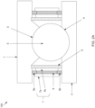
- FIG. 1 there is shown a cross-section of a rolling bearing assembly 100 that is generally circular (or ring shaped).
- the cross-section view is of the top of the circular rolling bearing assembly 100.
- a shaft (not shown) extending horizontally across the page may be below the shown cross-section.
- a similar cross-section (not shown) of the bottom of the circular rolling bearing assembly 100 would be below the shaft. Therefore, if the shaft and the bottom cross-section are included in the drawing, a top of the shaft is in contact with the inner ring 2 of the shown cross-section of the top part and the bottom of the shaft is in contact with inner ring 2 of the cross-section of the bottom part. Note that the inner ring of the bottom part would be above the outer ring of the bottom part. Therefore, the shaft would be encircled by the inner ring 2.
- a rolling bearing assembly 100 with electrical discharge damage protection comprises an inner ring 2 and an outer ring 1, where the inner ring 2 includes an inner ring raceway 4 and the outer ring 1 includes an outer ring raceway 3.
- the rolling bearing assembly 100 includes a plurality of rolling elements 5, where the plurality of rolling elements 5 are supported to roll on the inner ring raceway 4 and/or the inner ring raceway 3. At times the rolling elements 5 may contact both the inner ring raceway 4 and the outer ring raceway 3. At other times the rolling elements 5 may contact only one of the inner ring raceway 4 or the outer ring raceway 3. This may depend, for example, on the load and the location of the load on the rolling bearing assembly 100.
- the rolling elements 5 may be of different appropriate shapes for different example rolling bearing assembly 100.
- the rolling bearing elements 5 may be spherical, cylindrical, or other appropriate shapes.
- the rolling bearing assembly 100 may further include at least one ring 7 that does not directly contact either of the inner ring 2 or the outer ring 1.
- the at least one ring 7 may be electrically conductive or not.
- the at least one ring 7 may comprise, for example, a first ring 7a and a second ring 7b.
- An electrically conductive part 8 may be fixed to at least one of the first ring 7a and/or the second ring 7b, where the electrically conductive part 8 contacts the inner ring 2 and the outer ring 1.
- the electrically conductive part 8 may comprise, for example, filaments. While the term “filaments" is used for ease of application, it should be understood that “filaments” may refer to a single filament or multiple filaments.
- an example of the disclosure may have the electrically conductive part 8 with end pieces 8a and/or 8b that are filaments.
- the electrically conductive part 8 may be coupled to the ring 7 via a bracket (or cap) 9 as shown in FIGS. 3A and 3B .
- the end pieces 8a and 8b may be attached to the electrically conductive part 8 via a cap 10 as shown in FIG. 3C , screwed in, or via any other method appropriate for attaching the end pieces 8a and 8b to the electrically conductive part 8.
- the rolling bearing assembly 100 may also include a seal 6 that is integrally connected to the at least one ring 7 that may contact the inner ring 2 and/or outer ring 1.
- FIGS. 1 and 2 show one seal 6 coupled to only one side of the ring 7b.
- various examples of the disclosure may allow a plurality of seals 6, with one or more seals 6 coupled to one or both sides of the ring 7.
- the seal 6 are shown to be between the electrically conductive part 8 and the rolling elements 5.
- the seal 6 is shown to be between the rolling elements 5 and the second ring 7b of the ring 7.
- FIGS. 1 and 2 there is an electrical path between the inner ring 2 and the outer ring 1 such that voltage at the motor shaft can be dissipated without damaging the rolling elements 5.
- the electrically conductive part 8 may be fastened (or coupled, attached, etc.) to the ring 7 by one or many methods that are suitable for such a purpose.
- the electrically conductive part 8 may be fastened to one or both of the first ring 7a and the second ring 7b by using an adhesive.
- FIGS. 1 and 2 show the ring 7 on both sides of the rolling elements 5.
- the ring 7 may not be a ring.
- FIG. 5 illustrates a side view of the rolling bearing assembly 100.
- FIG. 5 shows the rolling bearing assembly 100 with the outer ring 1 and the inner ring 2, where the ring 7 comprises at least one discrete part between the inner ring 2 and the outer ring 1, and where the at least one discrete part is not a ring.
- FIG. 5 shows 4 discrete electrically conductive parts 7 between the outer ring 1 and the inner ring 2 that do not touch either of the outer ring 1 or the inner ring 2.
- These discrete electrically conductive parts 7 may have similar accessory parts such as the corresponding seals 6 and electrically conductive part 8.
- These discrete electrically conductive parts 7 may also comprise a first ring 7a and a second ring 7b.
- the ring 7 of FIG. 5 may also be coupled to the electrically conductive part 8 and the seal 6 as described previously. It may be noted that the electrically conductive part 8 may also be discrete parts or a ring coupled to the discrete parts of the ring 7.
- discrete electrically conductive parts of the ring 7 While four discrete electrically conductive parts of the ring 7 are shown, various examples of disclosure may have one or more electrically discrete conductive parts of the ring 7. Additionally, the shape of the discrete electrically conductive parts of the 7 may be different than the example of rectangles shown in FIG. 5 .
- FIG. 2B is similar to FIG. 1 except that the seal 6 is next to the electrically conductive part 8 without a ring 7 in between. It can also be seen that another example of the disclosure can have the ring 7 between the seal 6 and the electrically conductive part 8 without another ring 7 on the other side of the electrically conductive part 8. Additionally, rather than have the ring 7 on both sides of the rolling elements 5, there may only be a single ring 7 on one side of the rolling elements 5.
- FIGS. 3A and 3B illustrate a cap or bracket 9 that may be a part of the electrically conductive part 8.
- the cap 9 may fit over, for example, an end of the ring 7. Accordingly, the cap 9 may be configured such that the electrically conductive part 8 may be attached to either end or both ends of the first ring 7a or the second ring 7b.
- the cap 9 may also be used to couple to the first ring 7a and the second ring 7b. While it is referred to as a "cap,” the cap 9 may also be a pin or a screw configured to fit into, for example, a hole at an end of the ring 7.
- FIG. 3C illustrates a cap (or bracket) 10 that allows filaments 8a and 8b to fit on ends of the central part 8c.
- the central part 8c need not be electrically conductive. Rather, the filaments 8a and 8b enable electrical conduction from the inner ring 2 to one of the filaments 8a or 8b to the ring 7 to the other of the filaments 8b or 8a to the outer ring 1.
- the electrically conductive part 8 without the filaments 8a and 8b is made of conductive material, and/or when the central part 8c is conductive with the conductive filaments 8a and 8b, the ring 7 can be a nonconductive material. Whether the ring 7 is conductive or not, the ring 7 (whether one or more) may act as a brace for the electrically conducive part 8 and/or the seal 6.
- This fixing/coupling may be permanently fixed or removably fixed.
- permanently fixing/coupling two objects may be when separating the two objects is difficult or may result in one or both of the objects being damaged.
- permanently fixing may be adhesives that is not meant to be dissolved or loosened, mechanical fastening such as riveting, crimping, force fitting, welding, etc.
- Removably fixing/coupling may indicate that the two objects are intended to be taken apart such that they, or replacement parts, can be fixed/coupled again.
- removably fixing/coupling may use adhesives that can be dissolved or loosened, or use mechanical fastening mechanisms such as screws, bolts, latches, hook and loop fasteners, etc. It may be noted that a fastening process may be considered to be permanent or removable depending on the amount of effort needed to remove and to couple.
- Some examples of mechanical fastening may include crimping, staking, riveting, pressing (or interference fit), using screws/bolts, using hook and loop fasteners, latches, applying force by tension or compression, etc. or other technologies that may be useful in devices such as bearing assemblies described herein.
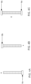
- FIGs. 4A, 4B, and 4C provide illustrations of lips at one or both ends of the seal 6.
- a lip 6a at a bottom end of the seal 6.
- a lip 6b at a top end of the seal 6.
- FIG. 4C there are shown lips 6a and 6b at the bottom end of the seal 6 and the top end of the seal 6, respectively.
- the lips 6a and/or 6b may be flexible lips.
- the seal 6 may also be a flexible seal.
- the seal 6 may be made of similar material as the lips 6a, 6b or different material.
- a bearing assembly that comprises, for example, an inner ring with an inner ring raceway, an outer ring with an outer ring raceway, rolling elements configured to roll or rotate between the inner ring raceway and the outer ring raceway.
- the rolling elements may touch one or both of the inner ring raceway and the outer ring raceway at different times depending on loading on the bearing assembly at a specific time.
- the bearing assembly may also comprise at least one electrically conductive part with a first end and a second end, where the first end is configured to electrically contact the inner ring and the second end is configured to electrically contact the outer ring.
- the bearing assembly may comprise first electrically conductive brush filaments coupled to the first end and second electrically conductive brush filaments coupled to the second end, where the first end is configured to electrically contact the inner ring via the first electrically conductive brush filaments and the second end is configured to electrically contact the outer ring via the second electrically conductive brush filaments. While “filaments” is used for ease of description, it should be understood that “filaments” is used in this disclosure can refer to a single filament or to multiple filaments.
- the first electrically conductive brush filaments may be removably coupled to the first end, and the second electrically conductive brush filaments may be removably coupled to the second end.
- the brush filaments may be held by a cap that fits over the first end or the second end.
- the brush filaments may be held by a holder such that the holder fits into a hole in the first end or the second end.
- the brush filaments may fit into the hole without a holder. Accordingly, it can be seen that the brush filaments may be removably coupled to the electrically conductive part.
- various aspects of the disclosure may also allow for permanently coupling the brush filaments to the electrically conductive part.
- the at least one electrically conductive part comprises electrically conductive brush filaments, where a first end of the electrically conductive brush filaments is the first end of the electrically conductive part, and a second end of the electrically conductive brush filaments is the second end of the electrically conductive part.
- the at least one electrically conductive part may directly contact the inner ring and the outer ring.
- the at least one electrically conductive part may be a seal.
- the seal comprises a surface that faces the rolling elements and a surface that faces away from the rolling elements. where a portion near a first surface of the electrically conductive part facing away from the rolling elements comprises electrically conductive brush filaments.
- the seal may comprise a sealing lip that contacts one of the inner ring or the outer ring, and the sealing lip may be a flexible sealing lip.
- a bearing assembly generally has one of the inner ring or the outer ring stationary, and the other of the inner ring or the outer ring in motion, the sealing lip may contact the moving ring and the other end of the seal may be fixed to the corresponding ring.
- some aspects of the disclosure may allow both ends of a seal to be non-fixed.
- the electrically conductive part may have a first electrically conductive part and a second electrically conductive part on opposite sides of the rolling elements, or the electrically conductive part may be on only one side of one of the rolling elements.
- the electrically conductive part may be a conductive ring between the inner ring and the outer ring, where the conductive ring may be continuous.
- the electrically conductive part may be discrete pieces that connect the inner ring to the outer ring. The discrete pieces may be thought of as pillars for ease of description, although various aspects of the disclosure may have different shapes, including arcs.
- the electrically conductive part may have one end fixed to one of the inner ring or the outer ring, and the other end not fixed to the other of the inner ring or the outer ring.
- Various aspects of the disclosure may also comprise a bearing assembly with an inner ring comprising an inner ring raceway, an outer ring comprising an outer ring raceway, and rolling elements configured to roll or rotate between the inner ring raceway and the outer ring raceway.
- the bearing assembly may also comprise at least one brace, and electrically conductive brush filaments, fastened to the at least one brace, with a first end and a second end.
- the at least one brace does not directly contact either of the inner ring or the outer ring, and the first end of the electrically conductive brush filament is configured to directly electrically contact the inner ring and the second end of the electrically conductive brush filaments is configured to directly electrically contact the outer ring.
- the electrically conductive brush filaments may be fastened to the at least one brace with an adhesive or the electrically conductive brush filaments may be mechanically fastened to the at least one brace.
- the bearing assembly may also comprise a seal between the rolling elements and one or both of the at least one brace and electrically conductive brush filaments.
- the at least one brace may be a first brace between the electrically conductive brush filaments and the seal, where the seal is coupled to a side of the first brace that faces at least one of the rolling elements.
- the seal may have a sealing lip that contacts one of the inner ring or the outer ring, where the sealing lip may be flexible. The seal may directly touch both of the inner ring and the outer ring.
- the seal, the at least one brace, and the electrically conductive brush filaments may be coupled together.
- Various aspects of the disclosure may be such that two or more of adjacent ones of the seal, the at least one brace, and the electrically conductive brush filaments are removably coupled together.
- the at least one brace may comprise a first brace coupled to a first side of the electrically conductive brush filaments that faces at least one of the rolling elements and a second brace coupled to a second side of the electrically conductive brush filaments that faces away from at least one of the rolling elements.
- One or both of the first brace and the second brace may be removably coupled to the electrically conductive brush filaments.
- the electrically conductive brush filaments comprise a first electrically conductive brush filaments and a second electrically conductive brush filaments on opposite sides of the rolling elements. Or, the electrically conductive brush filaments may be on only one side of one of the rolling elements.
- the electrically conductive brush filaments is a conductive ring.
- the electrically conductive brush filaments comprise at least one discrete part that is not a ring.
- the electrically conductive brush filaments may have a first electrically conductive brush filaments and a second electrically conductive brush filaments on opposite sides of the rolling elements, or the electrically conductive brush filaments may be on only one side of the rolling elements.
- the electrically conductive brush filaments may be a conductive ring between the inner ring and the outer ring, where the conductive ring may be continuous.
- the electrically conductive brush filaments may be discrete pieces that connect the inner ring to the outer ring.
- the discrete pieces may be thought of as pillars for ease of description, although various aspects of the disclosure may have different shapes, including arcs. It may also be noted that since the inner ring and the outer ring move with respect to each other, the electrically conductive brush filaments may have one end fixed to one of the inner ring or the outer ring, and the other end not fixed.
- the disclosure may also provide for a rolling bearing assembly with electrical discharge damage protection that comprises an inner ring and an outer ring.
- the inner ring includes an inner ring raceway and the outer ring includes an outer ring raceway.
- a plurality of rolling elements may be supported to roll on the inner ring raceway and the inner ring raceway.
- a seal may extend radially between the outer ring and the inner ring, where the seal includes a fixed seal end that is fixed to one of the inner ring or the outer ring and a the other end that contacts the other one of the inner ring or outer ring, where the other end may be a flexible sealing lip.
- the rolling bearing assembly may comprise at least one electrically conductive ring, and the seal may be integrally connected to the at least one electrically conductive ring.
- the at least one electrically conductive ring may have electrically conductive brush filaments fixed to at least one end.
- the electrically conductive brush filaments may electrically connect the inner ring and the outer ring to the electrically conductive ring.
- x and/or y means any element of the three-element set ⁇ (x), (y), (x, y) ⁇ . In other words, “x and/or y” means “one or both of x and y”.
- x, y, and/or z means any element of the seven-element set ⁇ (x), (y), (z), (x, y), (x, z), (y, z), (x, y, z) ⁇ . In other words, "x, y and/or z” means “one or more of x, y and z”.
- the term “exemplary” means serving as a non-limiting example, instance, or illustration.
- the terms "e.g.,” and “for example” set off lists of one or more non-limiting examples, instances, or illustrations.
Landscapes
- Engineering & Computer Science (AREA)
- General Engineering & Computer Science (AREA)
- Mechanical Engineering (AREA)
- Rolling Contact Bearings (AREA)
- Sealing With Elastic Sealing Lips (AREA)
- Sealing Devices (AREA)
- Sealing Of Bearings (AREA)
- Motor Or Generator Frames (AREA)
Abstract
Description
- This patent application makes reference to, claims priority to and claims benefit from
United States Provisional Patent Application Serial No. 62/726,897, filed on September 4, 2018 U.S. Patent Application No. 16/558,923, filed on September 3, 2019 - The present disclosure relates to electrical discharge damage remediation, and more particularly, to methods and apparatus for a rolling bearing assembly with electrical discharge damage protection.
- Limitations and disadvantages of conventional approaches will become apparent to one of skill in the art, through comparison of such approaches with some aspects of the present methods and system set forth in the remainder of this disclosure with reference to the drawings.
- Methods and systems are provided for a rolling bearing assembly with electrical discharge damage protection, substantially as illustrated by and described in connection with at least one of the figures, as set forth more completely in the claims.
- These and/or other aspects will become apparent and more readily appreciated from the following description of the exemplary embodiments, taken in conjunction with the accompanying drawings.
-
FIG. 1 illustrates a cross-section view of an example rolling bearing assembly with electrical discharge damage protection, in accordance with aspects of this disclosure. -
FIG. 2A illustrates a cross-section view of another example rolling bearing assembly with electrical discharge damage protection, in accordance with aspects of this disclosure. -
FIG. 2B illustrates a cross-section view of yet another example rolling bearing assembly with electrical discharge damage protection, in accordance with aspects of this disclosure. -
FIGs. 3A, 3B, and 3C illustrate example caps for coupling conductive brush filaments onto another part, in accordance with aspects of this disclosure. -
FIGs. 4A, 4B, and 4C illustrate example sealing lips, in accordance with aspects of this disclosure. -
FIG. 5 illustrates a side view of a rolling bearing assembly with electrical discharge damage protection, in accordance with aspects of this disclosure. - Generally, a rolling bearing assembly may be used to allow smoother rotations of a rotor in, for example, an electric motor. However, voltages may be created on motor shafts, and the built-up voltage can discharge through the bearings. Discharging of the voltage can damage the rolling bearings such that, over time, the rolling bearing assembly will need to be replaced for continued operation of the motor.
- Various examples of the disclosure describe a rolling bearing assembly with electrical discharge damage protection.
- In
FIG. 1 , there is shown a cross-section of a rollingbearing assembly 100 that is generally circular (or ring shaped). The cross-section view is of the top of the circular rollingbearing assembly 100. Accordingly, a shaft (not shown) extending horizontally across the page may be below the shown cross-section. A similar cross-section (not shown) of the bottom of the circular rollingbearing assembly 100 would be below the shaft. Therefore, if the shaft and the bottom cross-section are included in the drawing, a top of the shaft is in contact with theinner ring 2 of the shown cross-section of the top part and the bottom of the shaft is in contact withinner ring 2 of the cross-section of the bottom part. Note that the inner ring of the bottom part would be above the outer ring of the bottom part. Therefore, the shaft would be encircled by theinner ring 2. - A rolling
bearing assembly 100 with electrical discharge damage protection comprises aninner ring 2 and anouter ring 1, where theinner ring 2 includes aninner ring raceway 4 and theouter ring 1 includes anouter ring raceway 3. The rollingbearing assembly 100 includes a plurality ofrolling elements 5, where the plurality ofrolling elements 5 are supported to roll on theinner ring raceway 4 and/or theinner ring raceway 3. At times therolling elements 5 may contact both theinner ring raceway 4 and theouter ring raceway 3. At other times therolling elements 5 may contact only one of theinner ring raceway 4 or theouter ring raceway 3. This may depend, for example, on the load and the location of the load on the rollingbearing assembly 100. Therolling elements 5 may be of different appropriate shapes for different example rollingbearing assembly 100. For example, the rolling bearingelements 5 may be spherical, cylindrical, or other appropriate shapes. - The rolling
bearing assembly 100 may further include at least onering 7 that does not directly contact either of theinner ring 2 or theouter ring 1. The at least onering 7 may be electrically conductive or not. The at least onering 7 may comprise, for example, afirst ring 7a and asecond ring 7b. An electricallyconductive part 8 may be fixed to at least one of thefirst ring 7a and/or thesecond ring 7b, where the electricallyconductive part 8 contacts theinner ring 2 and theouter ring 1. The electricallyconductive part 8 may comprise, for example, filaments. While the term "filaments" is used for ease of application, it should be understood that "filaments" may refer to a single filament or multiple filaments. - As shown in
FIG. 2A , an example of the disclosure may have the electricallyconductive part 8 withend pieces 8a and/or 8b that are filaments. The electricallyconductive part 8 may be coupled to thering 7 via a bracket (or cap) 9 as shown inFIGS. 3A and 3B . Theend pieces conductive part 8 via acap 10 as shown inFIG. 3C , screwed in, or via any other method appropriate for attaching theend pieces conductive part 8. - The rolling
bearing assembly 100 may also include aseal 6 that is integrally connected to the at least onering 7 that may contact theinner ring 2 and/orouter ring 1.FIGS. 1 and2 show oneseal 6 coupled to only one side of thering 7b. However, various examples of the disclosure may allow a plurality ofseals 6, with one ormore seals 6 coupled to one or both sides of thering 7. Theseal 6 are shown to be between the electricallyconductive part 8 and therolling elements 5. InFIGS. 1 and2 , theseal 6 is shown to be between therolling elements 5 and thesecond ring 7b of thering 7. - As shown, in
FIGS. 1 and2 there is an electrical path between theinner ring 2 and theouter ring 1 such that voltage at the motor shaft can be dissipated without damaging therolling elements 5. - The electrically
conductive part 8 may be fastened (or coupled, attached, etc.) to thering 7 by one or many methods that are suitable for such a purpose. For example, the electricallyconductive part 8 may be fastened to one or both of thefirst ring 7a and thesecond ring 7b by using an adhesive. -
FIGS. 1 and2 show thering 7 on both sides of therolling elements 5. However, other examples of the disclosure may have thering 7 on only one side of therolling elements 5. In some examples of the disclosure, thering 7 may not be a ring. - For example,
FIG. 5 illustrates a side view of the rollingbearing assembly 100.FIG. 5 shows the rollingbearing assembly 100 with theouter ring 1 and theinner ring 2, where thering 7 comprises at least one discrete part between theinner ring 2 and theouter ring 1, and where the at least one discrete part is not a ring. For example,FIG. 5 shows 4 discrete electricallyconductive parts 7 between theouter ring 1 and theinner ring 2 that do not touch either of theouter ring 1 or theinner ring 2. These discrete electricallyconductive parts 7 may have similar accessory parts such as the correspondingseals 6 and electricallyconductive part 8. These discrete electricallyconductive parts 7 may also comprise afirst ring 7a and asecond ring 7b. Thering 7 ofFIG. 5 may also be coupled to the electricallyconductive part 8 and theseal 6 as described previously. It may be noted that the electricallyconductive part 8 may also be discrete parts or a ring coupled to the discrete parts of thering 7. - While four discrete electrically conductive parts of the
ring 7 are shown, various examples of disclosure may have one or more electrically discrete conductive parts of thering 7. Additionally, the shape of the discrete electrically conductive parts of the 7 may be different than the example of rectangles shown inFIG. 5 . -
FIG. 2B is similar toFIG. 1 except that theseal 6 is next to the electricallyconductive part 8 without aring 7 in between. It can also be seen that another example of the disclosure can have thering 7 between theseal 6 and the electricallyconductive part 8 without anotherring 7 on the other side of the electricallyconductive part 8. Additionally, rather than have thering 7 on both sides of the rollingelements 5, there may only be asingle ring 7 on one side of the rollingelements 5. -
FIGS. 3A and 3B illustrate a cap orbracket 9 that may be a part of the electricallyconductive part 8. Thecap 9 may fit over, for example, an end of thering 7. Accordingly, thecap 9 may be configured such that the electricallyconductive part 8 may be attached to either end or both ends of thefirst ring 7a or thesecond ring 7b. Thecap 9 may also be used to couple to thefirst ring 7a and thesecond ring 7b. While it is referred to as a "cap," thecap 9 may also be a pin or a screw configured to fit into, for example, a hole at an end of thering 7. -
FIG. 3C illustrates a cap (or bracket) 10 that allowsfilaments central part 8c. While referred to as the electricallyconductive part 8, when fitted with thefilaments central part 8c need not be electrically conductive. Rather, thefilaments inner ring 2 to one of thefilaments ring 7 to the other of thefilaments outer ring 1. Similarly, when the electricallyconductive part 8, without thefilaments central part 8c is conductive with theconductive filaments ring 7 can be a nonconductive material. Whether thering 7 is conductive or not, the ring 7 (whether one or more) may act as a brace for the electricallyconducive part 8 and/or theseal 6. - Various items may be discussed as being "fastened," "attached," "fixed," or "coupled" to each other. This fixing/coupling may be permanently fixed or removably fixed. For example, permanently fixing/coupling two objects may be when separating the two objects is difficult or may result in one or both of the objects being damaged. Examples of permanently fixing may be adhesives that is not meant to be dissolved or loosened, mechanical fastening such as riveting, crimping, force fitting, welding, etc. Removably fixing/coupling may indicate that the two objects are intended to be taken apart such that they, or replacement parts, can be fixed/coupled again. For example, removably fixing/coupling may use adhesives that can be dissolved or loosened, or use mechanical fastening mechanisms such as screws, bolts, latches, hook and loop fasteners, etc. It may be noted that a fastening process may be considered to be permanent or removable depending on the amount of effort needed to remove and to couple.
- Some examples of mechanical fastening, without regard to whether the fastening is removable or permanent, or whether any may apply to an example of the disclosure, may include crimping, staking, riveting, pressing (or interference fit), using screws/bolts, using hook and loop fasteners, latches, applying force by tension or compression, etc. or other technologies that may be useful in devices such as bearing assemblies described herein.
-
FIGs. 4A, 4B, and 4C provide illustrations of lips at one or both ends of theseal 6. InFIG. 4A , there is shown alip 6a at a bottom end of theseal 6. InFIG. 4B , there is shown alip 6b at a top end of theseal 6. InFIG. 4C , there are shownlips seal 6 and the top end of theseal 6, respectively. Thelips 6a and/or 6b may be flexible lips. Theseal 6 may also be a flexible seal. In various aspects of the disclosure, theseal 6 may be made of similar material as thelips - Therefore, it can be seen that the disclosure provides for a bearing assembly that comprises, for example, an inner ring with an inner ring raceway, an outer ring with an outer ring raceway, rolling elements configured to roll or rotate between the inner ring raceway and the outer ring raceway. The rolling elements may touch one or both of the inner ring raceway and the outer ring raceway at different times depending on loading on the bearing assembly at a specific time. The bearing assembly may also comprise at least one electrically conductive part with a first end and a second end, where the first end is configured to electrically contact the inner ring and the second end is configured to electrically contact the outer ring.
- The bearing assembly may comprise first electrically conductive brush filaments coupled to the first end and second electrically conductive brush filaments coupled to the second end, where the first end is configured to electrically contact the inner ring via the first electrically conductive brush filaments and the second end is configured to electrically contact the outer ring via the second electrically conductive brush filaments. While "filaments" is used for ease of description, it should be understood that "filaments" is used in this disclosure can refer to a single filament or to multiple filaments.
- The first electrically conductive brush filaments may be removably coupled to the first end, and the second electrically conductive brush filaments may be removably coupled to the second end. For example, the brush filaments may be held by a cap that fits over the first end or the second end. Or the brush filaments may be held by a holder such that the holder fits into a hole in the first end or the second end. Or the brush filaments may fit into the hole without a holder. Accordingly, it can be seen that the brush filaments may be removably coupled to the electrically conductive part. However, various aspects of the disclosure may also allow for permanently coupling the brush filaments to the electrically conductive part.
- The at least one electrically conductive part comprises electrically conductive brush filaments, where a first end of the electrically conductive brush filaments is the first end of the electrically conductive part, and a second end of the electrically conductive brush filaments is the second end of the electrically conductive part. The at least one electrically conductive part may directly contact the inner ring and the outer ring.
- The at least one electrically conductive part may be a seal. The seal comprises a surface that faces the rolling elements and a surface that faces away from the rolling elements. where a portion near a first surface of the electrically conductive part facing away from the rolling elements comprises electrically conductive brush filaments. The seal may comprise a sealing lip that contacts one of the inner ring or the outer ring, and the sealing lip may be a flexible sealing lip.
- As a bearing assembly generally has one of the inner ring or the outer ring stationary, and the other of the inner ring or the outer ring in motion, the sealing lip may contact the moving ring and the other end of the seal may be fixed to the corresponding ring. However, some aspects of the disclosure may allow both ends of a seal to be non-fixed.
- The electrically conductive part may have a first electrically conductive part and a second electrically conductive part on opposite sides of the rolling elements, or the electrically conductive part may be on only one side of one of the rolling elements. In some aspects of the disclosure, the electrically conductive part may be a conductive ring between the inner ring and the outer ring, where the conductive ring may be continuous. In other aspects of the disclosure, the electrically conductive part may be discrete pieces that connect the inner ring to the outer ring. The discrete pieces may be thought of as pillars for ease of description, although various aspects of the disclosure may have different shapes, including arcs. It may also be noted that since the inner ring and the outer ring move with respect to each other, the electrically conductive part may have one end fixed to one of the inner ring or the outer ring, and the other end not fixed to the other of the inner ring or the outer ring.
- Various aspects of the disclosure may also comprise a bearing assembly with an inner ring comprising an inner ring raceway, an outer ring comprising an outer ring raceway, and rolling elements configured to roll or rotate between the inner ring raceway and the outer ring raceway. The bearing assembly may also comprise at least one brace, and electrically conductive brush filaments, fastened to the at least one brace, with a first end and a second end. The at least one brace does not directly contact either of the inner ring or the outer ring, and the first end of the electrically conductive brush filament is configured to directly electrically contact the inner ring and the second end of the electrically conductive brush filaments is configured to directly electrically contact the outer ring.
- The electrically conductive brush filaments may be fastened to the at least one brace with an adhesive or the electrically conductive brush filaments may be mechanically fastened to the at least one brace. The bearing assembly may also comprise a seal between the rolling elements and one or both of the at least one brace and electrically conductive brush filaments. The at least one brace may be a first brace between the electrically conductive brush filaments and the seal, where the seal is coupled to a side of the first brace that faces at least one of the rolling elements. The seal may have a sealing lip that contacts one of the inner ring or the outer ring, where the sealing lip may be flexible. The seal may directly touch both of the inner ring and the outer ring.
- The seal, the at least one brace, and the electrically conductive brush filaments may be coupled together. Various aspects of the disclosure may be such that two or more of adjacent ones of the seal, the at least one brace, and the electrically conductive brush filaments are removably coupled together.
- The at least one brace may comprise a first brace coupled to a first side of the electrically conductive brush filaments that faces at least one of the rolling elements and a second brace coupled to a second side of the electrically conductive brush filaments that faces away from at least one of the rolling elements. One or both of the first brace and the second brace may be removably coupled to the electrically conductive brush filaments.
- The electrically conductive brush filaments comprise a first electrically conductive brush filaments and a second electrically conductive brush filaments on opposite sides of the rolling elements. Or, the electrically conductive brush filaments may be on only one side of one of the rolling elements.
- The electrically conductive brush filaments is a conductive ring. The electrically conductive brush filaments comprise at least one discrete part that is not a ring. Similarly as described previously, the electrically conductive brush filaments may have a first electrically conductive brush filaments and a second electrically conductive brush filaments on opposite sides of the rolling elements, or the electrically conductive brush filaments may be on only one side of the rolling elements. In some aspects of the disclosure, the electrically conductive brush filaments may be a conductive ring between the inner ring and the outer ring, where the conductive ring may be continuous. In other aspects of the disclosure, the electrically conductive brush filaments may be discrete pieces that connect the inner ring to the outer ring. The discrete pieces may be thought of as pillars for ease of description, although various aspects of the disclosure may have different shapes, including arcs. It may also be noted that since the inner ring and the outer ring move with respect to each other, the electrically conductive brush filaments may have one end fixed to one of the inner ring or the outer ring, and the other end not fixed.
- The disclosure may also provide for a rolling bearing assembly with electrical discharge damage protection that comprises an inner ring and an outer ring. The inner ring includes an inner ring raceway and the outer ring includes an outer ring raceway. A plurality of rolling elements may be supported to roll on the inner ring raceway and the inner ring raceway. A seal may extend radially between the outer ring and the inner ring, where the seal includes a fixed seal end that is fixed to one of the inner ring or the outer ring and a the other end that contacts the other one of the inner ring or outer ring, where the other end may be a flexible sealing lip.
- The rolling bearing assembly may comprise at least one electrically conductive ring, and the seal may be integrally connected to the at least one electrically conductive ring. The at least one electrically conductive ring may have electrically conductive brush filaments fixed to at least one end. The electrically conductive brush filaments may electrically connect the inner ring and the outer ring to the electrically conductive ring.
- As utilized herein, "and/or" means any one or more of the items in the list joined by "and/or." As an example, "x and/or y" means any element of the three-element set {(x), (y), (x, y)}. In other words, "x and/or y" means "one or both of x and y". As another example, "x, y, and/or z" means any element of the seven-element set {(x), (y), (z), (x, y), (x, z), (y, z), (x, y, z)}. In other words, "x, y and/or z" means "one or more of x, y and z". As utilized herein, the term "exemplary" means serving as a non-limiting example, instance, or illustration. As utilized herein, the terms "e.g.," and "for example" set off lists of one or more non-limiting examples, instances, or illustrations.
- While the present method and/or system has been described with reference to certain implementations, it will be understood by those skilled in the art that various changes may be made and equivalents may be substituted without departing from the scope of the present method and/or system. In addition, many modifications may be made to adapt a particular situation or material to the teachings of the present disclosure without departing from its scope. Therefore, the present method and/or system are not limited to the particular implementations disclosed. Instead, the present method and/or system will include all implementations falling within the scope of the appended claims, both literally and under the doctrine of equivalents.
- Further examples of the disclosure are presented in the below clauses, which are not to be confused with the claim.
-
Clause 1. A bearing assembly, comprising:- an inner ring comprising an inner ring raceway;
- an outer ring comprising an outer ring raceway;
- rolling elements configured to roll or rotate between the inner ring raceway and the outer ring raceway; and
- at least one electrically conductive part with a first end and a second end, wherein the first end is configured to electrically contact the inner ring and the second end is configured to electrically contact the outer ring.
-
Clause 2. The bearing assembly ofclause 1, comprising first electrically conductive brush filaments coupled to the first end and second electrically conductive brush filaments coupled to the second end, wherein the first end is configured to electrically contact the inner ring via the first electrically conductive brush filaments and the second end is configured to electrically contact the outer ring via the second electrically conductive brush filaments. -
Clause 3. The bearing assembly ofclause 2, wherein:- the first electrically conductive brush filaments are removably coupled to the first end, and
- the second electrically conductive brush filaments are removably coupled to the second end.
-
Clause 4. The bearing assembly ofclause 1, wherein:- the at least one electrically conductive part comprises electrically conductive brush filaments,
- a first end of the electrically conductive brush filaments is the first end of the electrically conductive part, and
- a second end of the electrically conductive brush filaments is the second end of the electrically conductive part.
-
Clause 5. The bearing assembly ofclause 1, wherein the at least one electrically conductive part is a seal. -
Clause 6. The bearing assembly ofclause 5, wherein the seal comprises a sealing lip that contacts one of the inner ring or the outer ring. -
Clause 7. The bearing assembly ofclause 6, wherein the sealing lip is a flexible sealing lip. -
Clause 8. The bearing assembly ofclause 1, wherein the at least one electrically conductive part comprises at least one discrete part that is not a ring. -
Clause 9. A bearing assembly, comprising:- an inner ring comprising an inner ring raceway;
- an outer ring comprising an outer ring raceway;
- rolling elements configured to roll or rotate between the inner ring raceway and the outer ring raceway;
- at least one brace; and
- electrically conductive brush filaments, fastened to the at least one brace, with a first end and a second end,
- wherein:
- the at least one brace does not directly contact either of the inner ring or the outer ring, and
- the first end is configured to directly electrically contact the inner ring and the second end is configured to directly electrically contact the outer ring.
-
Clause 10. The bearing assembly ofclause 9, comprising a seal between the rolling elements and one or both of the at least one brace and the electrically conductive brush filaments. - Clause 11. The bearing assembly of
clause 10, wherein the seal comprises a sealing lip that contacts one of the inner ring or the outer ring. - Clause 12. The bearing assembly of
clause 10, wherein the seal, the at least one brace, and the electrically conductive brush filaments are coupled together. - Clause 13. The bearing assembly of
clause 10, wherein two or more of adjacent ones of the seal, the at least one brace, and the electrically conductive brush filaments are removably coupled together. - Clause 14. The bearing assembly of
clause 9, wherein the electrically conductive brush filaments is on only one side of one of the rolling elements. - Clause 15. The bearing assembly of
clause 9, wherein the electrically conductive brush filaments is a conductive ring. - Clause 16. The bearing assembly of
clause 9, wherein the electrically conductive brush filaments comprise at least one discrete part that is not a ring. - Clause 17. A rolling bearing assembly with electrical discharge damage protection, comprising:
- an inner ring and an outer ring, the inner ring including an inner ring raceway and the outer ring including an outer ring raceway;
- a plurality of rolling elements, the plurality of rolling elements are supported to roll on the inner ring raceway and the inner ring raceway; and
- a seal extending radially between the outer ring and the inner ring, the seal including a fixed seal end that is fixed to one of the inner ring or the outer ring and a flexible sealing lip that contacts the other one of the inner ring or the outer ring.
- Clause 18. The rolling bearing assembly of clause 17, comprising at least one electrically conductive ring.
- Clause 19. The rolling bearing assembly of clause 18, wherein the seal is integrally connected to the at least one electrically conductive ring.
- Clause 20. The rolling bearing assembly of clause 18, wherein the at least one electrically conductive ring has electrically conductive brush filaments fixed to at least one end.
Claims (12)
- A bearing assembly, comprising:an inner ring comprising an inner ring raceway;an outer ring comprising an outer ring raceway;rolling elements configured to roll or rotate between the inner ring raceway and the outer ring raceway;at least one brace; andelectrically conductive brush filaments, fastened to the at least one brace, with a first end and a second end,wherein:the at least one brace does not directly contact either of the inner ring or the outer ring, andthe first end is configured to directly electrically contact the inner ring and the second end is configured to directly electrically contact the outer ring.
- The bearing assembly of claim 1, comprising a seal between the rolling elements and one or both of the at least one brace and the electrically conductive brush filaments.
- The bearing assembly of claim 2, wherein the seal comprises a sealing lip that contacts one of the inner ring or the outer ring.
- The bearing assembly of claim 2, wherein the seal, the at least one brace, and the electrically conductive brush filaments are coupled together.
- The bearing assembly of claim 2, wherein two or more of adjacent ones of the seal, the at least one brace, and the electrically conductive brush filaments are removably coupled together.
- The bearing assembly of claim 1, wherein the electrically conductive brush filaments is on only one side of one of the rolling elements.
- The bearing assembly of claim 1, wherein the electrically conductive brush filaments is a conductive ring.
- The bearing assembly of claim 1, wherein the electrically conductive brush filaments comprise at least one discrete part that is not a ring.
- A rolling bearing assembly with electrical discharge damage protection, comprising:an inner ring and an outer ring, the inner ring including an inner ring raceway and the outer ring including an outer ring raceway;a plurality of rolling elements, the plurality of rolling elements are supported to roll on the inner ring raceway and the inner ring raceway; anda seal extending radially between the outer ring and the inner ring, the seal including a fixed seal end that is fixed to one of the inner ring or the outer ring and a flexible sealing lip that contacts the other one of the inner ring or the outer ring.
- The rolling bearing assembly of claim 9, comprising at least one electrically conductive ring.
- The rolling bearing assembly of claim 10, wherein the seal is integrally connected to the at least one electrically conductive ring.
- The rolling bearing assembly of claim 10, wherein the at least one electrically conductive ring has electrically conductive brush filaments fixed to at least one end.
Applications Claiming Priority (4)
| Application Number | Priority Date | Filing Date | Title |
|---|---|---|---|
| US201862726897P | 2018-09-04 | 2018-09-04 | |
| US16/558,923 US11028882B2 (en) | 2018-09-04 | 2019-09-03 | Methods and apparatus for a rolling bearing assembly with electrical discharge damage protection |
| EP19850858.2A EP3847381B1 (en) | 2018-09-04 | 2019-09-04 | Apparatus for a rolling bearing assembly with electrical discharge damage protection |
| PCT/US2019/049521 WO2020060760A2 (en) | 2018-09-04 | 2019-09-04 | Method and apparatus for a rolling bearing assembly with electrical discharge damage protection |
Related Parent Applications (2)
| Application Number | Title | Priority Date | Filing Date |
|---|---|---|---|
| EP19850858.2A Division EP3847381B1 (en) | 2018-09-04 | 2019-09-04 | Apparatus for a rolling bearing assembly with electrical discharge damage protection |
| EP19850858.2A Division-Into EP3847381B1 (en) | 2018-09-04 | 2019-09-04 | Apparatus for a rolling bearing assembly with electrical discharge damage protection |
Publications (2)
| Publication Number | Publication Date |
|---|---|
| EP4155563A1 true EP4155563A1 (en) | 2023-03-29 |
| EP4155563B1 EP4155563B1 (en) | 2026-02-18 |
Family
ID=69642191
Family Applications (2)
| Application Number | Title | Priority Date | Filing Date |
|---|---|---|---|
| EP22207861.0A Active EP4155563B1 (en) | 2018-09-04 | 2019-09-04 | Rolling bearing assembly with electrical discharge damage protection |
| EP19850858.2A Active EP3847381B1 (en) | 2018-09-04 | 2019-09-04 | Apparatus for a rolling bearing assembly with electrical discharge damage protection |
Family Applications After (1)
| Application Number | Title | Priority Date | Filing Date |
|---|---|---|---|
| EP19850858.2A Active EP3847381B1 (en) | 2018-09-04 | 2019-09-04 | Apparatus for a rolling bearing assembly with electrical discharge damage protection |
Country Status (8)
| Country | Link |
|---|---|
| US (1) | US11028882B2 (en) |
| EP (2) | EP4155563B1 (en) |
| JP (1) | JP7449277B2 (en) |
| KR (2) | KR102817023B1 (en) |
| CN (1) | CN113167317A (en) |
| PL (1) | PL3847381T3 (en) |
| TW (1) | TWI816874B (en) |
| WO (1) | WO2020060760A2 (en) |
Families Citing this family (4)
| Publication number | Priority date | Publication date | Assignee | Title |
|---|---|---|---|---|
| CN114641921B (en) * | 2019-12-11 | 2024-04-02 | 舍弗勒技术股份两合公司 | Discharge device for discharging electric charge from a rotor of an electric motor |
| DE102020125005A1 (en) | 2020-09-25 | 2021-12-30 | Schaeffler Technologies AG & Co. KG | Rolling bearing arrangement |
| JP2024117595A (en) * | 2023-02-17 | 2024-08-29 | 中西金属工業株式会社 | Bearing seal |
| WO2025224881A1 (en) * | 2024-04-24 | 2025-10-30 | 株式会社ジェイテクトシーリングテクノ | Sliding member and rolling bearing |
Citations (6)
| Publication number | Priority date | Publication date | Assignee | Title |
|---|---|---|---|---|
| JP2009079643A (en) * | 2007-09-26 | 2009-04-16 | Nsk Ltd | Energizing type rolling bearing |
| WO2009056098A1 (en) * | 2007-10-31 | 2009-05-07 | Schaeffler Kg | Sealing element for a bearing, in particular for an anti-friction bearing |
| US20140334758A1 (en) * | 2013-05-09 | 2014-11-13 | Schaeffler Technologies Gmbh & Co. Kg | Rolling bearing with integrated electrical shunt |
| US20160312834A1 (en) * | 2015-04-22 | 2016-10-27 | Schaeffler Technologies AG & Co. KG | Shunt bearing with insulating coating |
| US20170108047A1 (en) * | 2015-10-19 | 2017-04-20 | Schaeffler Technologies AG & Co. KG | Bearing seal with integrated grounding brush |
| DE102017106695B3 (en) * | 2017-03-29 | 2018-04-19 | Schaeffler Technologies AG & Co. KG | Rolling bearings with integrated current discharge function |
Family Cites Families (15)
| Publication number | Priority date | Publication date | Assignee | Title |
|---|---|---|---|---|
| US822723A (en) | 1904-02-23 | 1906-06-05 | Robert Conrad | Ball-bearing. |
| JP3654924B2 (en) * | 1994-03-24 | 2005-06-02 | 株式会社東芝 | Scanner motor for laser beam printer |
| CN200999862Y (en) * | 2006-12-01 | 2008-01-02 | 韶关东南轴承有限公司 | Double-layer type high sealing property sealed ring |
| JP2009156298A (en) | 2007-12-25 | 2009-07-16 | Jtekt Corp | Rolling bearing |
| JP2010106971A (en) | 2008-10-30 | 2010-05-13 | Ntn Corp | Rolling bearing |
| CN201575047U (en) * | 2009-11-02 | 2010-09-08 | 浙江八环轴承有限公司 | Double-sealed bearing |
| CN103573830A (en) * | 2013-11-12 | 2014-02-12 | 无锡华洋滚动轴承有限公司 | High-temperature-resisting oil-pressure double-layer rubber sealing ball bearing |
| CN112118217B9 (en) | 2015-01-16 | 2023-05-09 | 三星电子株式会社 | Control information transmission method and device in wireless communication system |
| US10190640B2 (en) | 2016-03-23 | 2019-01-29 | Schaeffler Technologies AG & Co. KG | Bearing with integrated shunt |
| US11396865B2 (en) * | 2016-07-05 | 2022-07-26 | Vestas Wind Systems A/S | Wind turbine generator with an electric generator bearing assembly |
| US10253815B2 (en) | 2017-08-29 | 2019-04-09 | Schaeffler Technologies AG & Co. KG | Rolling bearing assembly including a crimped sealing assembly having a grounding element |
| US10422384B2 (en) * | 2018-01-25 | 2019-09-24 | Aktiebolaget Skf | Electrical insulating device for bearings |
| US10927897B2 (en) * | 2018-09-04 | 2021-02-23 | Illinois Tool Works Inc. | Method and apparatus for a rolling bearing assembly with electrical discharge damage protection |
| US10612599B2 (en) * | 2018-09-12 | 2020-04-07 | Schaeffler Technologies As & Co. Kg | Bearing seal with integrated grounding shunt |
| US10578164B1 (en) * | 2018-09-26 | 2020-03-03 | Schaeffleer Technologies Ag & Co. Kg | Bearing having integrated soft connected grounding device |
-
2019
- 2019-09-03 US US16/558,923 patent/US11028882B2/en active Active
- 2019-09-04 EP EP22207861.0A patent/EP4155563B1/en active Active
- 2019-09-04 KR KR1020217007271A patent/KR102817023B1/en active Active
- 2019-09-04 PL PL19850858.2T patent/PL3847381T3/en unknown
- 2019-09-04 WO PCT/US2019/049521 patent/WO2020060760A2/en not_active Ceased
- 2019-09-04 TW TW108131884A patent/TWI816874B/en active
- 2019-09-04 EP EP19850858.2A patent/EP3847381B1/en active Active
- 2019-09-04 JP JP2021512543A patent/JP7449277B2/en active Active
- 2019-09-04 KR KR1020257003891A patent/KR20250024124A/en active Pending
- 2019-09-04 CN CN201980057149.4A patent/CN113167317A/en active Pending
Patent Citations (6)
| Publication number | Priority date | Publication date | Assignee | Title |
|---|---|---|---|---|
| JP2009079643A (en) * | 2007-09-26 | 2009-04-16 | Nsk Ltd | Energizing type rolling bearing |
| WO2009056098A1 (en) * | 2007-10-31 | 2009-05-07 | Schaeffler Kg | Sealing element for a bearing, in particular for an anti-friction bearing |
| US20140334758A1 (en) * | 2013-05-09 | 2014-11-13 | Schaeffler Technologies Gmbh & Co. Kg | Rolling bearing with integrated electrical shunt |
| US20160312834A1 (en) * | 2015-04-22 | 2016-10-27 | Schaeffler Technologies AG & Co. KG | Shunt bearing with insulating coating |
| US20170108047A1 (en) * | 2015-10-19 | 2017-04-20 | Schaeffler Technologies AG & Co. KG | Bearing seal with integrated grounding brush |
| DE102017106695B3 (en) * | 2017-03-29 | 2018-04-19 | Schaeffler Technologies AG & Co. KG | Rolling bearings with integrated current discharge function |
Also Published As
| Publication number | Publication date |
|---|---|
| JP2021536555A (en) | 2021-12-27 |
| KR20250024124A (en) | 2025-02-18 |
| PL3847381T3 (en) | 2023-06-26 |
| KR102817023B1 (en) | 2025-06-04 |
| CN113167317A (en) | 2021-07-23 |
| EP3847381A2 (en) | 2021-07-14 |
| JP7449277B2 (en) | 2024-03-13 |
| WO2020060760A2 (en) | 2020-03-26 |
| EP4155563B1 (en) | 2026-02-18 |
| US20200072289A1 (en) | 2020-03-05 |
| EP3847381B1 (en) | 2023-02-22 |
| TW202024500A (en) | 2020-07-01 |
| KR20210049835A (en) | 2021-05-06 |
| TWI816874B (en) | 2023-10-01 |
| WO2020060760A3 (en) | 2020-05-14 |
| US11028882B2 (en) | 2021-06-08 |
Similar Documents
| Publication | Publication Date | Title |
|---|---|---|
| EP3847380B1 (en) | Apparatus for a rolling bearing assembly with electrical discharge damage protection | |
| EP3847381B1 (en) | Apparatus for a rolling bearing assembly with electrical discharge damage protection | |
| JP6163480B2 (en) | Current shunt ring | |
| EP2727225B1 (en) | Current control brush assembly | |
| WO2013062988A2 (en) | Current control brush assembly | |
| WO1999013553A1 (en) | Replaceable bearing cartridge assembly for flywheel energy system | |
| US11637477B2 (en) | Rotating machine | |
| US9419501B1 (en) | Constant force shaft grounding brush holder | |
| CN1750363A (en) | Ground brushes to moderate current on motor shaft | |
| EP0744252A1 (en) | Seal device for rotary portion, and industrial robot provided at rotary portion thereof with seal device | |
| US20240154505A1 (en) | Potential equalisation arrangement for an electric motor | |
| US20220131448A1 (en) | Systems and methods for threaded fasteners with grounding brush endpoints | |
| US20250129819A1 (en) | Electrolytic corrosion prevention member for rolling bearing and electrolytic corrosion prevention rolling bearing unit | |
| US12607230B2 (en) | Electrolytic corrosion prevention member for rolling bearing and electrolytic corrosion prevention rolling bearing unit | |
| CN211936244U (en) | Zeolite runner sealing device and zeolite runner system | |
| EP4526982A1 (en) | Modular sealing system and an electric motor with such a modular sealing system | |
| HK1169739B (en) | Current diverter ring |
Legal Events
| Date | Code | Title | Description |
|---|---|---|---|
| PUAI | Public reference made under article 153(3) epc to a published international application that has entered the european phase |
Free format text: ORIGINAL CODE: 0009012 |
|
| STAA | Information on the status of an ep patent application or granted ep patent |
Free format text: STATUS: THE APPLICATION HAS BEEN PUBLISHED |
|
| AC | Divisional application: reference to earlier application |
Ref document number: 3847381 Country of ref document: EP Kind code of ref document: P |
|
| AK | Designated contracting states |
Kind code of ref document: A1 Designated state(s): AL AT BE BG CH CY CZ DE DK EE ES FI FR GB GR HR HU IE IS IT LI LT LU LV MC MK MT NL NO PL PT RO RS SE SI SK SM TR |
|
| STAA | Information on the status of an ep patent application or granted ep patent |
Free format text: STATUS: REQUEST FOR EXAMINATION WAS MADE |
|
| 17P | Request for examination filed |
Effective date: 20230925 |
|
| RBV | Designated contracting states (corrected) |
Designated state(s): AL AT BE BG CH CY CZ DE DK EE ES FI FR GB GR HR HU IE IS IT LI LT LU LV MC MK MT NL NO PL PT RO RS SE SI SK SM TR |
|
| STAA | Information on the status of an ep patent application or granted ep patent |
Free format text: STATUS: EXAMINATION IS IN PROGRESS |
|
| 17Q | First examination report despatched |
Effective date: 20240510 |
|
| GRAP | Despatch of communication of intention to grant a patent |
Free format text: ORIGINAL CODE: EPIDOSNIGR1 |
|
| STAA | Information on the status of an ep patent application or granted ep patent |
Free format text: STATUS: GRANT OF PATENT IS INTENDED |
|
| INTG | Intention to grant announced |
Effective date: 20251007 |
|
| P01 | Opt-out of the competence of the unified patent court (upc) registered |
Free format text: CASE NUMBER: UPC_APP_0013721_4155563/2025 Effective date: 20251117 |
|
| GRAS | Grant fee paid |
Free format text: ORIGINAL CODE: EPIDOSNIGR3 |
|
| GRAA | (expected) grant |
Free format text: ORIGINAL CODE: 0009210 |
|
| STAA | Information on the status of an ep patent application or granted ep patent |
Free format text: STATUS: THE PATENT HAS BEEN GRANTED |
|
| AC | Divisional application: reference to earlier application |
Ref document number: 3847381 Country of ref document: EP Kind code of ref document: P |
|
| AK | Designated contracting states |
Kind code of ref document: B1 Designated state(s): AL AT BE BG CH CY CZ DE DK EE ES FI FR GB GR HR HU IE IS IT LI LT LU LV MC MK MT NL NO PL PT RO RS SE SI SK SM TR |
|
| REG | Reference to a national code |
Ref country code: CH Ref legal event code: F10 Free format text: ST27 STATUS EVENT CODE: U-0-0-F10-F00 (AS PROVIDED BY THE NATIONAL OFFICE) Effective date: 20260218 Ref country code: GB Ref legal event code: FG4D |
|
| REG | Reference to a national code |
Ref country code: IE Ref legal event code: FG4D |
|
| REG | Reference to a national code |
Ref country code: DE Ref legal event code: R096 Ref document number: 602019081666 Country of ref document: DE |
|
| REG | Reference to a national code |
Ref country code: NL Ref legal event code: MP Effective date: 20260218 |
|
| PG25 | Lapsed in a contracting state [announced via postgrant information from national office to epo] |
Ref country code: RS Free format text: LAPSE BECAUSE OF FAILURE TO SUBMIT A TRANSLATION OF THE DESCRIPTION OR TO PAY THE FEE WITHIN THE PRESCRIBED TIME-LIMIT Effective date: 20260518 |
|
| PG25 | Lapsed in a contracting state [announced via postgrant information from national office to epo] |
Ref country code: ES Free format text: LAPSE BECAUSE OF FAILURE TO SUBMIT A TRANSLATION OF THE DESCRIPTION OR TO PAY THE FEE WITHIN THE PRESCRIBED TIME-LIMIT Effective date: 20260218 |
|
| PG25 | Lapsed in a contracting state [announced via postgrant information from national office to epo] |
Ref country code: GR Free format text: LAPSE BECAUSE OF FAILURE TO SUBMIT A TRANSLATION OF THE DESCRIPTION OR TO PAY THE FEE WITHIN THE PRESCRIBED TIME-LIMIT Effective date: 20260519 |
|
| REG | Reference to a national code |
Ref country code: LT Ref legal event code: MG9D |
|
| PG25 | Lapsed in a contracting state [announced via postgrant information from national office to epo] |
Ref country code: LT Free format text: LAPSE BECAUSE OF FAILURE TO SUBMIT A TRANSLATION OF THE DESCRIPTION OR TO PAY THE FEE WITHIN THE PRESCRIBED TIME-LIMIT Effective date: 20260218 |
|
| PG25 | Lapsed in a contracting state [announced via postgrant information from national office to epo] |
Ref country code: NO Free format text: LAPSE BECAUSE OF FAILURE TO SUBMIT A TRANSLATION OF THE DESCRIPTION OR TO PAY THE FEE WITHIN THE PRESCRIBED TIME-LIMIT Effective date: 20260518 |
|
| PG25 | Lapsed in a contracting state [announced via postgrant information from national office to epo] |
Ref country code: FI Free format text: LAPSE BECAUSE OF FAILURE TO SUBMIT A TRANSLATION OF THE DESCRIPTION OR TO PAY THE FEE WITHIN THE PRESCRIBED TIME-LIMIT Effective date: 20260218 Ref country code: SE Free format text: LAPSE BECAUSE OF FAILURE TO SUBMIT A TRANSLATION OF THE DESCRIPTION OR TO PAY THE FEE WITHIN THE PRESCRIBED TIME-LIMIT Effective date: 20260218 Ref country code: AT Free format text: LAPSE BECAUSE OF FAILURE TO SUBMIT A TRANSLATION OF THE DESCRIPTION OR TO PAY THE FEE WITHIN THE PRESCRIBED TIME-LIMIT Effective date: 20260218 |
|
| REG | Reference to a national code |
Ref country code: AT Ref legal event code: MK05 Ref document number: 1888311 Country of ref document: AT Kind code of ref document: T Effective date: 20260218 |
|
| PG25 | Lapsed in a contracting state [announced via postgrant information from national office to epo] |
Ref country code: HR Free format text: LAPSE BECAUSE OF FAILURE TO SUBMIT A TRANSLATION OF THE DESCRIPTION OR TO PAY THE FEE WITHIN THE PRESCRIBED TIME-LIMIT Effective date: 20260218 |
|
| PG25 | Lapsed in a contracting state [announced via postgrant information from national office to epo] |
Ref country code: IS Free format text: LAPSE BECAUSE OF FAILURE TO SUBMIT A TRANSLATION OF THE DESCRIPTION OR TO PAY THE FEE WITHIN THE PRESCRIBED TIME-LIMIT Effective date: 20260618 Ref country code: PT Free format text: LAPSE BECAUSE OF FAILURE TO SUBMIT A TRANSLATION OF THE DESCRIPTION OR TO PAY THE FEE WITHIN THE PRESCRIBED TIME-LIMIT Effective date: 20260618 |
|
| PG25 | Lapsed in a contracting state [announced via postgrant information from national office to epo] |
Ref country code: NL Free format text: LAPSE BECAUSE OF FAILURE TO SUBMIT A TRANSLATION OF THE DESCRIPTION OR TO PAY THE FEE WITHIN THE PRESCRIBED TIME-LIMIT Effective date: 20260218 |
|
| PG25 | Lapsed in a contracting state [announced via postgrant information from national office to epo] |
Ref country code: LV Free format text: LAPSE BECAUSE OF FAILURE TO SUBMIT A TRANSLATION OF THE DESCRIPTION OR TO PAY THE FEE WITHIN THE PRESCRIBED TIME-LIMIT Effective date: 20260218 |
|
| PG25 | Lapsed in a contracting state [announced via postgrant information from national office to epo] |
Ref country code: BG Free format text: LAPSE BECAUSE OF FAILURE TO SUBMIT A TRANSLATION OF THE DESCRIPTION OR TO PAY THE FEE WITHIN THE PRESCRIBED TIME-LIMIT Effective date: 20260218 |