EP4155528A1 - High-pressure fuel supply pump - Google Patents
High-pressure fuel supply pump Download PDFInfo
- Publication number
- EP4155528A1 EP4155528A1 EP21809840.8A EP21809840A EP4155528A1 EP 4155528 A1 EP4155528 A1 EP 4155528A1 EP 21809840 A EP21809840 A EP 21809840A EP 4155528 A1 EP4155528 A1 EP 4155528A1
- Authority
- EP
- European Patent Office
- Prior art keywords
- pump body
- peripheral surface
- pressure fuel
- fuel supply
- welding
- Prior art date
- Legal status (The legal status is an assumption and is not a legal conclusion. Google has not performed a legal analysis and makes no representation as to the accuracy of the status listed.)
- Granted
Links
Images



Classifications
-
- F—MECHANICAL ENGINEERING; LIGHTING; HEATING; WEAPONS; BLASTING
- F02—COMBUSTION ENGINES; HOT-GAS OR COMBUSTION-PRODUCT ENGINE PLANTS
- F02M—SUPPLYING COMBUSTION ENGINES IN GENERAL WITH COMBUSTIBLE MIXTURES OR CONSTITUENTS THEREOF
- F02M59/00—Pumps specially adapted for fuel-injection and not provided for in groups F02M39/00 -F02M57/00, e.g. rotary cylinder-block type of pumps
- F02M59/44—Details, components parts, or accessories not provided for in, or of interest apart from, the apparatus of groups F02M59/02 - F02M59/42; Pumps having transducers, e.g. to measure displacement of pump rack or piston
-
- F—MECHANICAL ENGINEERING; LIGHTING; HEATING; WEAPONS; BLASTING
- F02—COMBUSTION ENGINES; HOT-GAS OR COMBUSTION-PRODUCT ENGINE PLANTS
- F02M—SUPPLYING COMBUSTION ENGINES IN GENERAL WITH COMBUSTIBLE MIXTURES OR CONSTITUENTS THEREOF
- F02M59/00—Pumps specially adapted for fuel-injection and not provided for in groups F02M39/00 -F02M57/00, e.g. rotary cylinder-block type of pumps
- F02M59/44—Details, components parts, or accessories not provided for in, or of interest apart from, the apparatus of groups F02M59/02 - F02M59/42; Pumps having transducers, e.g. to measure displacement of pump rack or piston
- F02M59/48—Assembling; Disassembling; Replacing
-
- F—MECHANICAL ENGINEERING; LIGHTING; HEATING; WEAPONS; BLASTING
- F02—COMBUSTION ENGINES; HOT-GAS OR COMBUSTION-PRODUCT ENGINE PLANTS
- F02M—SUPPLYING COMBUSTION ENGINES IN GENERAL WITH COMBUSTIBLE MIXTURES OR CONSTITUENTS THEREOF
- F02M2200/00—Details of fuel-injection apparatus, not otherwise provided for
- F02M2200/80—Fuel injection apparatus manufacture, repair or assembly
- F02M2200/8084—Fuel injection apparatus manufacture, repair or assembly involving welding or soldering
Definitions
- the present invention relates to a high-pressure fuel supply pump, and more particularly to a high-pressure fuel supply pump in which a functional member such as a discharge joint is joined to a pump body having a pressurizing chamber for pressurizing fuel by welding.
- a high-pressure fuel supply pump for increasing a pressure of fuel is widely used.
- Some high-pressure fuel supply pumps include a pump body having a pressurizing chamber for pressurizing fuel, to which functional components such as a discharge joint and an electromagnetic suction valve mechanism are joined by welding (see, for example, PTL 1).
- a discharge joint is inserted into a hole formed in an outer peripheral surface of a pump body, and an inner peripheral portion of the hole of the pump body and an outer peripheral portion of the discharge joint are fixed by welding at contact surfaces thereof.
- a space is formed on the side opposite to the outer peripheral surface of the pump body with respect to the welding portion joining the pump body and the discharge joint. This space prevents formation of a notch having an acute angle, a notch having a small corner radius, or the like at the terminal end portion of the welding portion where stress concentration occurs.
- This space is formed by, for example, the annular recessed shape of the pump body and the annular recessed shape of the discharge joint.
- the inner peripheral portion of the hole of the pump body and the outer peripheral portion of the discharge joint are brought into contact with each other on the deep side of the hole with respect to the space described above, thereby preventing the spatter generated during welding from entering the pump body.
- the inner peripheral portion of the hole of the pump body and the outer peripheral portion of the discharge joint are brought into contact with each other on the deeper side of the hole than the annular recessed shape of the pump body and the discharge joint. Therefore, in the current structure, it is difficult to further increase the curvature radius of the contour curve of the annular concave shape of the pump body.
- the present invention has been made to solve the above problems, and an object of the present invention is to provide a high-pressure fuel supply pump capable of reducing the stress generated in the portion forming the space provided for the welding portion while preventing the spatter from entering the pump.
- the present application includes a plurality of means for solving the above problems, and there is a high-pressure fuel supply pump, as an example thereof, including: a pump body provided with a hole on an outer surface; a functional component attached to the hole of the pump body; and a welding portion configured to join the pump body and the functional component.
- a space portion is formed between the pump body and the functional component from a terminal end portion of the welding portion in a penetration direction toward a deep side of the hole of the pump body.
- the functional component includes: an end surface of the hole in a depth direction; and an outer peripheral surface rising from an outer edge of the end surface.
- a wall surface forming the hole of the pump body includes: a facing surface facing the end surface of the functional component; and an inner peripheral surface located outside the outer peripheral surface of the functional component and extending from an outer edge of the facing surface to the terminal end portion of the welding portion.
- the end surface of the functional component and the facing surface of the pump body form a gap having a size within a predetermined range.
- the space portion is formed from the terminal end portion of the welding portion to a range of the facing surface of the pump body.
- the entire inner peripheral surface of the pump body from the terminal end portion of the welding portion to the facing surface is formed as a concave curved surface to constitute a part of a wall surface of the space portion.
- the spatter is prevented from entering the pump by the combination of the end surface of the functional component and the facing surface of the pump body facing the end surface, it is possible to reduce the curvature of the concave curved surface of the inner peripheral surface of the pump body forming the space portion by extending the space portion provided for the welding portion to the range up to the facing surface of the pump body. Therefore, it is possible to reduce the stress generated on the inner peripheral surface of the pump body forming the space portion while preventing the spatter from entering the pump.
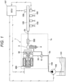
- FIG. 1 is a configuration diagram illustrating the fuel supply system for the internal combustion engine including the high-pressure fuel supply pump according to the embodiment of the present invention.
- FIG. 1 a portion surrounded by a broken line indicates a pump body which is a main body of the high-pressure fuel supply pump.
- the mechanisms and components illustrated in the broken lines indicate that they are incorporated in the pump body.
- FIG. 1 is a diagram schematically illustrating a configuration of a fuel supply system, and the configuration of the high-pressure fuel supply pump illustrated in FIG. 1 is different from the configuration illustrated in FIG. 2 and subsequent drawings described later.
- a fuel supply system of an internal combustion engine includes, for example, a fuel tank 101 that stores fuel, a feed pump 102 that pumps up and delivers the fuel in the fuel tank 101, a high-pressure fuel supply pump 1 that pressurizes and discharges the fuel delivered from the feed pump 102, and a plurality of injectors 103 that injects high-pressure fuel pressure-fed from the high-pressure fuel supply pump 1.
- the high-pressure fuel supply pump 1 is connected to the feed pump 102 via a suction pipe 104 and is connected to the injector 103 via a common rail 105.
- the injector 103 is mounted on the common rail 105 according to the number of cylinders of the engine.
- a pressure sensor 106 that detects the pressure of the fuel discharged from the high-pressure fuel supply pump 1 is attached to the common rail 105.
- the present system is a system that directly injects fuel into a cylinder of an engine, a so-called direct injection engine system.
- the high-pressure fuel supply pump 1 includes a pump body 1a having a pressurizing chamber 3 for pressurizing fuel therein, a plunger 4 assembled to a pump body 1a, an electromagnetic suction valve mechanism 300, and a discharge valve mechanism 500.
- the plunger 4 pressurizes the fuel in the pressurizing chamber 3 by reciprocating motion.
- the electromagnetic suction valve mechanism 300 functions as a variable capacity mechanism that adjusts a flow rate of fuel sucked into the pressurizing chamber 3.
- the discharge valve mechanism 500 discharges the fuel pressurized by the plunger 4 toward the common rail 105.
- a pressure pulsation reduction mechanism 12 that reduces propagation of pressure pulsation generated in the high-pressure fuel supply pump 1 to the suction pipe 104 is provided upstream of the electromagnetic suction valve mechanism 300.
- the feed pump 102, the electromagnetic suction valve mechanism 300 of the high-pressure fuel supply pump 1, and the injector 103 are electrically connected to an engine control unit (hereinafter, referred to as ECU) 107, and are controlled by a control signal output from the ECU 107.
- ECU engine control unit
- the detection signal from the pressure sensor 106 is input to the ECU 107.
- the fuel in the fuel tank 101 is pumped up by the feed pump 102 driven based on a control signal of the ECU 107.
- This fuel is pressurized to an appropriate feed pressure by the feed pump 102 and sent to a low-pressure fuel suction port 2a of the high-pressure fuel supply pump 1 through the suction pipe 104.
- the fuel that has passed through the low-pressure fuel suction port 2a reaches the electromagnetic suction valve mechanism 300 via the pressure pulsation reduction mechanism 12 and a suction passage 2d.
- the fuel flowing into the electromagnetic suction valve mechanism 300 passes through an opening opened and closed by a suction valve 30.
- the fuel is sucked into the pressurizing chamber 3 during a downward stroke of the plunger 4 which reciprocates, and is pressurized in the pressurizing chamber 3 during an upward stroke of the plunger 4.
- the pressurized fuel is pressure-fed from the discharge valve mechanism 500 to the common rail 105 via a fuel discharge port 2h.
- the high-pressure fuel in the common rail 105 is injected into each cylinder of the engine by each injector 103 driven based on a control signal of the ECU 107.
- the high-pressure fuel supply pump 1 discharges a desired flow rate of fuel by opening and closing the suction valve 30 of the electromagnetic suction valve mechanism 300 according to a control signal from the ECU 107 to the electromagnetic suction valve mechanism 300.
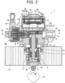
- FIG. 2 is a longitudinal cross-sectional view illustrating the high-pressure fuel supply pump according to the first embodiment of the present invention.
- FIG. 3 is a longitudinal cross-sectional view of the high-pressure fuel supply pump according to the first embodiment of the present invention taken along a cross section different from the longitudinal cross-sectional view illustrated in FIG. 2 .
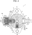
- FIG. 4 is a cross-sectional view of the high-pressure fuel supply pump according to the first embodiment of the present invention illustrated in FIG. 2 , as viewed from the direction of arrow IV-IV.
- the high-pressure fuel supply pump 1 includes a pump body 1a having a pressurizing chamber 3 for pressurizing fuel therein, a plunger 4 assembled to the pump body 1a, an electromagnetic suction valve mechanism 300 (shown in FIGS. 2 and 4 ), a discharge valve mechanism 500 (shown only in FIG. 4 ), and a relief valve mechanism 600 (shown only in FIG. 2 ).
- the high-pressure fuel supply pump 1 is in close contact with a pump mounting portion 111 (illustrated in FIGS. 2 and 3 ) of the engine via a mounting flange 1b provided in the pump body 1a, and is fixed by a plurality of bolts (not illustrated).
- An O-ring 15 shown in FIGS.
- the O-ring 15 seals between the pump mounting portion 111 and the pump body 1a, and prevents engine oil and the like from leaking out of the engine.
- an insertion hole 1d extending in the longitudinal direction is formed in the central portion of the pump body 1a, and a cylinder 5 is press-fitted and attached to the insertion hole 1d.
- the cylinder 5 guides the reciprocating motion of the plunger 4, and forms a part of the pressurizing chamber 3 together with the pump body 1a.
- a fixing portion 1c provided at an opening edge portion of the insertion hole 1d of the pump body 1a is engaged with a central portion in the axial direction of the cylinder 5.
- the fixing portion 1c presses the cylinder 5 toward the pressurizing chamber 3, and seals so that the fuel pressurized in the pressurizing chamber 3 does not leak to the low pressure side from between the end surface of the cylinder 5 and the wall surface of the insertion hole 1d of the pump body 1a.
- a tappet 6 is provided on the leading end side (lower end side in FIGS. 2 and 3 ) of the plunger 4.
- the tappet 6 converts rotational motion of a cam 112 attached to a cam shaft (not illustrated) of the engine into linear reciprocating motion and transmits the linear reciprocating motion to the plunger 4.
- the plunger 4 is crimped to the tappet 6 by the biasing force of the spring 8 via a retainer 7.
- the tappet 6 reciprocates with the rotational movement of the cam 112, so that the plunger 4 reciprocates along the cylinder 5, and the volume of the pressurizing chamber 3 increases or decreases.
- a seal holder 9 having a bottomed cylindrical portion is fixed to the pump body 1a on the engine side of the cylinder 5, and the plunger 4 penetrates the bottom of the seal holder 9.
- An auxiliary chamber 9a for storing fuel leaking from the pressurizing chamber 3 via a sliding portion between the plunger 4 and the cylinder 5 is formed inside the seal holder 9.
- a plunger seal 10 is held on the bottom side (lower end side in FIGS. 2 and 3 ) inside the seal holder 9.
- the plunger seal 10 is installed so that the outer peripheral surface of the plunger 4 is in contact with the plunger seal 10 in a slidable manner.
- the plunger seal 10 prevents the fuel in the auxiliary chamber 9a from flowing out to the engine side during the reciprocating motion of the plunger 4.
- the lubricating oil (including the engine oil) in the engine is prevented from flowing into the pump body 1a from the engine side.
- a cup-shaped cover 13 is attached to a distal end portion (upper end portion in FIGS. 2 and 3 ) of the pump body 1a on the side opposite to the engine.
- a low-pressure fuel chamber 2c is formed by the distal end portion of the pump body 1a and the cover 13.
- the pressure pulsation reduction mechanism 12 is disposed in the low-pressure fuel chamber 2c.
- the pressure pulsation reduction mechanism 12 includes, for example, two dampers 12a and a plurality of holding members 12b holding two dampers 12a in the low-pressure fuel chamber 2c.
- Each damper 12a is formed by overlapping two metal diaphragms and enclosing an inert gas in a space between both the metal diaphragms.
- the damper 12a expands and contracts to reduce pressure pulsation.
- the plurality of holding members 12b holds the two dampers 12a in the low-pressure fuel chamber 2c by sandwiching the two dampers between the cover 13 and the distal end portion of the pump body 1a.
- a suction joint 17 having the low-pressure fuel suction port 2a is attached to an outer peripheral surface portion of the cover 13.
- the suction pipe 104 (see FIG. 1 ) is connected to the suction joint 17, and fuel from the fuel tank 101 (see FIG. 1 ) is supplied to the inside of the high-pressure fuel supply pump 1 via the suction joint 17.
- a suction filter 18 is disposed in the flow path of the suction joint 17. The suction filter 18 serves to prevent foreign matter existing between the fuel tank 101 and the low-pressure fuel suction port 2a from being absorbed into the high-pressure fuel supply pump 1 by the flow of fuel.
- a first attachment hole 1f is provided in an outer peripheral surface (outer surface) 1e of the pump body 1a.
- the first attachment hole 1f communicates with the low-pressure fuel chamber 2c via the suction passage 2d formed in the pump body 1a, and communicates with the pressurizing chamber 3 via a suction passage 2e formed in the pump body 1a.
- the electromagnetic suction valve mechanism 300 is attached to the first attachment hole 1f.
- the electromagnetic suction valve mechanism 300 is roughly divided into a valve unit, an anchor unit, and a solenoid unit.
- the valve unit includes, for example, a suction valve 30, a suction valve seat 31, a suction valve biasing spring 32, a spring holder 33, and a suction valve stopper 34.
- the suction valve 30 includes a disk-shaped valve portion 30a and a rod portion 30b extending from a central portion of the valve portion 30a in a direction orthogonal to the valve portion 30a.
- the spring holder 33 is attached to a distal end portion of the rod portion 30b.
- a valve seat portion 31a on which the valve portion 30a of the suction valve 30 is seated or separated and a rod guide portion 31b that slidably supports the rod portion 30b of the suction valve 30 are integrally formed.
- the suction valve seat 31 is provided with a plurality of suction ports 31c communicating with the suction passage 2d of the pump body 1a.
- the suction valve biasing spring 32 is disposed in the rod guide portion 31b of the suction valve seat 31 and biases the suction valve 30 toward the valve seat portion 31a (valve closing direction) via the spring holder 33.
- the suction valve stopper 34 regulates a lift amount of the valve portion 30a of the suction valve 30.
- the anchor unit includes a housing 36 as a fixed portion, a magnetic core 37, an anchor guide 38, an anchor 39 and an anchor sleeve 40 integrally assembled as a movable portion, and an anchor biasing spring 41 that biases the movable portion.
- the housing 36 is formed in a bottomed cylindrical shape, and an opening portion is fitted to the suction valve seat 31 of the valve unit.
- the magnetic core 37, the anchor guide 38, the anchor 39, and the anchor sleeve 40 are disposed.
- the magnetic core 37 is formed in a cylindrical shape, and is fixed in contact with the inner peripheral surface on the bottom side in the housing 36.
- the anchor guide 38 is fixed to a bottom in the housing 36.
- the anchor guide 38 is formed in a columnar shape extending from the bottom of the housing 36 toward the opening, and is inserted into the magnetic core 37.
- the anchor 39 is formed in a cylindrical shape and is disposed so as to face an end surface on an opening side of the housing 36 in the axial direction of the magnetic core 37.
- the magnetic core 37 and the anchor 39 are arranged on an inner peripheral side of an electromagnetic coil 44 to be described later of the solenoid unit, and end surfaces of the magnetic core 37 and the anchor 39 facing each other constitute a magnetic attraction surface on which a magnetic attraction force acts.
- the anchor sleeve 40 is press-fitted and fixed to the inner peripheral side of the anchor 39, and the anchor 39 and the anchor sleeve 40 are integrally movable in the housing 36.
- the movement of the anchor 39 and the anchor sleeve 40 is guided by the outer peripheral surface of the anchor 39 sliding on the inner peripheral surface of the housing 36 and the anchor sleeve 40 sliding on the outer peripheral surface of the anchor guide 38.
- the anchor 39 and the anchor sleeve 40 of the movable portion are configured to be able to abut on the distal end portion of the rod portion 30b of the suction valve 30 of the valve unit.
- the anchor biasing spring 41 is disposed in a housing space formed between the inner peripheral surface of the magnetic core 37 and the outer peripheral surface of the anchor guide 38, and has one end portion side abutting on the anchor guide 38 which is a fixed portion and the other end portion side abutting on the anchor sleeve 40 which is a movable portion.
- the anchor biasing spring 41 biases the anchor 39 and the anchor sleeve 40 as the movable portion in a direction away from the magnetic core 37. That is, when no magnetic attraction force acts between the magnetic core 37 and the anchor 39, a clearance is generated between the magnetic core 37 and the anchor 39.
- the anchor 39 and the anchor sleeve 40 of the movable portion move against the biasing force of the anchor biasing spring 41, and the anchor 39 comes into contact with the magnetic core 37.
- the anchor 39 and the anchor sleeve 40 of the movable portion move in a direction away from the magnetic core 37 by the biasing force of the anchor biasing spring 41, the suction valve 30 of the valve unit is pressed, and the suction valve 30 is separated from the suction valve seat 31 and enters a valve opening state. That is, the anchor biasing spring 41 is configured to bias the anchor 39 and the anchor sleeve 40 of the movable portion in the valve opening direction.
- the solenoid unit includes, for example, a base member 43, an electromagnetic coil 44, and a connection terminal 45.
- the base member 43 is fitted to the outer peripheral side of the housing 36 of the anchor unit.
- the base member 43 is formed of a resin material or the like, and forms a connector fitting portion connectable to a connector fitting portion of a control line of the ECU 107 (see FIG. 1 ).
- the electromagnetic coil 44 is annularly formed on the outer peripheral side of the housing 36 of the anchor unit and is fixed to the base member 43.
- a part of the connection terminal 45 is embedded in the base member 43, and one end portion side thereof is electrically connected to the electromagnetic coil 44.
- connection terminal 45 is exposed in the connector fitting portion of the base member 43 and can be connected to a control line on the ECU 107 (see FIG. 1 ) side.
- the flow rate of fuel discharged at high pressure can be controlled to a flow rate required by the engine by controlling the energization timing to the electromagnetic coil 44.
- a second attachment hole 1g communicating with the pressurizing chamber 3 is provided at a position shifted in the circumferential direction from the first attachment hole 1f on the outer peripheral surface (outer surface) 1e of the pump body 1a.
- the discharge valve mechanism 500 as a functional component is attached to the second attachment hole 1g.
- the discharge valve mechanism 500 includes, for example, a discharge valve seat 51, a discharge valve 52 that can be seated on and separated from the discharge valve seat 51, a discharge valve spring 53 that biases the discharge valve 52 toward the discharge valve seat 51, and a discharge valve holder 54 that houses the discharge valve 52 and the discharge valve spring 53.
- the discharge valve holder 54 functions as a stopper that regulates the lift amount of the discharge valve 52.
- a plug 55 that closes the opening is disposed in the opening of the second attachment hole 1g.
- the plug 55 is joined to the side wall of the second attachment hole 1g of the pump body 1a by welding, and has a function of preventing fuel from leaking to the outside.
- the second attachment hole 1g in which the discharge valve mechanism 500 is disposed communicates with a fuel discharge port 2h described later via a discharge passage 2g formed in the pump body 1a.
- the discharge valve mechanism 500 is configured such that the discharge valve 52 is pressed against the discharge valve seat 51 by the biasing force of the discharge valve spring 53 to be in a closed state in a state where there is no fuel differential pressure between the pressurizing chamber 3 and the internal space on the secondary side of the discharge valve 52 (internal space communicating with the discharge passage 2g).
- the discharge valve 52 is opened against the biasing force of the discharge valve spring 53 only when the fuel pressure in the pressurizing chamber 3 becomes larger than the fuel pressure in the internal space on the secondary side of the discharge valve 52.
- the discharge valve mechanism 500 having the above configuration functions as a check valve that restricts the flow direction of the fuel.
- a third attachment hole 1h is provided on the outer peripheral surface (outer surface) 1e of the pump body 1a at a position opposite to the first attachment hole 1f across the pressurizing chamber 3.
- a discharge joint 19 as a functional component is attached to the third attachment hole 1h of the pump body 1a by welding.
- the discharge joint 19 has the fuel discharge port 2h for discharging pressurized fuel, and communicates with the common rail 105 (see FIG. 1 ). Details of a joint structure between the discharge joint 19 and the pump body 1a will be described later.
- a relief passage 2i connected to the pressurizing chamber 3 and the third attachment hole 1h is formed in the pump body 1a.
- the relief valve mechanism 600 is disposed across the relief passage 2i and the pressurizing chamber 3.
- the relief valve mechanism 600 includes, for example, a relief valve seat 61, a relief valve 62 that comes into contact with and separates from the relief valve seat 61, a relief valve holder 63 that holds the relief valve 62, and a relief spring 64 that biases the relief valve 62 toward the relief valve seat 61.
- the fuel passage of the relief valve seat 61 communicates with the fuel discharge port 2h of the discharge joint 19.
- One end side of the relief spring 64 is in contact with a wall surface forming the pressurizing chamber 3, and the other end side is in contact with the relief valve holder 63.
- the biasing force of the relief spring 64 acts via the relief valve holder 63 to press the relief valve 62 on the relief valve seat 61, whereby the relief valve 62 blocks the flow of the fuel.
- the valve opening pressure of the relief valve 62 is determined by the biasing force of the relief spring 64.
- the relief valve mechanism 600 is a valve mechanism configured to operate when some problem occurs in the common rail 105 (see FIG. 1 ) or a member beyond the common rail 105 and the common rail has an abnormally high pressure. That is, the relief valve mechanism 600 is configured such that the relief valve 62 opens against the biasing force of the relief spring 64 when the differential pressure between the upstream side (pressurizing chamber 3) and the downstream side of the relief valve 62 exceeds the set pressure.
- the relief valve mechanism 600 has a function of opening and returning the fuel to the pressurizing chamber 3 when the pressure in the common rail 105 increases.
- the relief valve mechanism 600 of the present embodiment is disposed across the relief passage 2i and the pressurizing chamber 3, the present invention is not limited thereto.
- the relief valve mechanism 600 can be disposed in the relief passage 2i communicating with a low-pressure passage such as the low-pressure fuel chamber 2c.
- the plunger 4 turns into an upward motion after the end of the downward motion.
- the electromagnetic coil 44 of the electromagnetic suction valve mechanism 300 remains in a non-energized state, and no magnetic biasing force is generated.
- the suction valve 30 is maintained in the valve opening state by the biasing force of the anchor biasing spring 41.
- the volume of the pressurizing chamber 3 decreases with the upward movement of the plunger 4, but in a state where the suction valve 30 is opened, the fuel once sucked into the pressurizing chamber 3 is returned to the suction passage 2d through the opening of the suction valve 30 again, so that the pressure in the pressurizing chamber 3 does not increase. This state is referred to as a return stroke.
- the suction valve 30 is closed by the biasing force of the suction valve biasing spring 32 of the electromagnetic suction valve mechanism 300 and the fluid force due to the fuel flowing into the suction passage 2d.
- the suction valve 30 By closing the suction valve 30, the fuel pressure in the pressurizing chamber 3 rises according to the rising motion of the plunger 4, and when the fuel pressure becomes equal to or higher than the pressure of the fuel discharge port 2h, the discharge valve 52 of the discharge valve mechanism 500 illustrated in FIG. 4 opens.
- the high-pressure fuel in the pressurizing chamber 3 is discharged from the fuel discharge port 2h via the discharge valve mechanism 500 and the discharge passage 2g and supplied to the common rail 105 (see FIG. 1 ). This state is referred to as a discharge stroke.
- the flow rate of the discharged high-pressure fuel can be controlled by the timing of energizing the electromagnetic coil 44 of the electromagnetic suction valve mechanism 300 illustrated in FIG. 2 . If the timing of energizing the electromagnetic coil 44 is advanced, the ratio of the return stroke during the upward movement of the plunger 4 decreases, and the ratio of the discharge stroke increases. In other words, the fuel returning to the suction passage 2d becomes less, and on the other hand the discharged high-pressure fuel becomes large. On the other hand, if the energization timing is delayed, the ratio of the return stroke during the rising motion increases, and the ratio of the discharge stroke decreases. In other words, the fuel returning to the suction passage 2d becomes large, and on the other hand the discharged high-pressure fuel becomes less.
- the timing for energizing the electromagnetic coil 44 is controlled by a command from the ECU 107.
- the strength in the vicinity of the welded joint to the pump body 1a of the discharge joint 19 that discharges the fuel increased in pressure is increased corresponding to the increase in pressure of the fuel.
- FIG. 5 is an enlarged cross-sectional view of a joint structure between the discharge joint and the pump body indicated by reference sign Z in FIG. 4 .
- the discharge joint 19 is a cylindrical member having an axis X, and includes a flow path 19a through which high-pressure fuel pressurized in the pressurizing chamber 3 flows.
- the discharge joint 19 is joined to the pump body 1a via a welding portion 90 in a state where one end portion 70 is inserted into the third attachment hole 1h of the pump body 1a.
- An annular space portion 91 is formed between the pump body 1a and the one end portion 70 of a discharge joint 19 from a terminal end portion 90b to be described later of the welding portion 90 in the penetration direction D toward the deep side of the third attachment hole 1h of the pump body 1a.
- the space portion 91 prevents formation of a notch having an acute angle or a notch having a small corner radius at the terminal end portion 90b of the welding portion where stress concentration occurs.
- the one end portion 70 of the discharge joint 19 is formed in, for example, a cylindrical shape, and has an annular end surface 71 (left end surface in FIG. 5 ) in the depth direction of the third attachment hole 1h and a cylindrical outer peripheral surface 72 extending from the outer edge of the end surface 71 to the terminal end portion 90b of the rising welding portion 90.
- the outer peripheral surface 72 constitutes a wall surface of the space portion 91 together with an inner peripheral surface 82 to be described later of the pump body 1a.
- the one end portion 70 of the discharge joint 19 has a tapered inclined surface 73 inclined with respect to the cylindrical outer peripheral surface 72 so as to gradually expand toward the outer peripheral side with increasing distance from the outer peripheral surface 72 in the state of the single component before being welded to the pump body 1a.
- the inclined surface 73 is a portion that abuts against an inclined surface 87 to be described later of the pump body 1a, and is a portion that is melted together with a part of the pump body 1a at the time of welding to become the welding portion 90.
- the discharge joint 19 has an annular flange portion 75 formed so as to protrude toward the outer peripheral side from the one end portion 70 and abut on the outer peripheral surface (outer surface) 1e of the pump body 1a in the state of a single component.
- the flange portion 75 is configured such that the end surface 71 of the discharge joint 19 is disposed at a position where a minute gap C to be described later is formed when the flange portion abuts on the outer surface of the pump body 1a. That is, the flange portion 75 functions as a positioning portion in the insertion direction of the third attachment hole 1h. Similarly to the inclined surface 73, the flange portion 75 is a portion that is melted together with a part of the pump body 1a at the time of welding to become the welding portion 90.
- the third attachment hole 1h of the pump body 1a has an axis extending in substantially the same direction as the axis X of the discharge joint 19.
- the wall surface forming the third attachment hole 1h of the pump body 1a has a facing surface 81 facing the end surface 71 of the discharge joint 19 and an inner peripheral surface 82 positioned outside the outer peripheral surface 72 of the discharge joint 19.
- the facing surface 81 constitutes, for example, a bottom surface of the third attachment hole 1h.
- the inner peripheral surface 82 constitutes a side surface of the third attachment hole 1h, and extends from the outer edge of the facing surface 81 to the terminal end portion 90b of the welding portion 90.
- the entire inner peripheral surface 82 from the terminal end portion 90b of the welding portion 90 to the outer edge of the facing surface 81 is formed as a concave curved surface.
- the entire inner peripheral surface 82 constitutes a wall surface of the space portion 91 together with the outer peripheral surface 72 of the discharge joint 19.
- a contour curve obtained by cutting the inner peripheral surface 82 along a plane orthogonal to the annular direction along the inner peripheral surface 82 includes a first curved portion 83 having one end 83a connected to the terminal end portion 90b of the welding portion 90 and a second curved portion 84 having one end 84a connected to the other end 83b of the first curved portion 83 and the other end 84b connected to the outer edge of the facing surface 81.
- the first curved portion 83 has a first curvature radius having a relatively large curvature radius.
- the second curved portion 84 has a second curvature radius smaller than the first curvature radius.
- the contour curves (meridian cross sections of the inner peripheral surface 82) 83 and 84 are configured such that a first length L1 of the third attachment hole 1h in the depth direction from the one end 83a to the other end 83b of the first curved portion 83 is longer than a second length L2 of the third attachment hole 1h in the depth direction from the one end 84a to the other end 84b of the second curved portion 84.
- the contour curves (meridian cross sections of the inner peripheral surface 82) 83 and 84 are formed such that a first area S1 surrounded by a perpendicular line PL (in FIG.
- a broken line drawn from the other end 83b of the first curved portion 83 (the one end 84a of the second curved portion 84) and the first curved portion 83 with respect to a line segment LS (in FIG. 5 , a broken line) connecting the one end 83a of the first curved portion 83 and the other end 84b of the second curved portion 84 among the portions surrounded by the contour curves 83 and 84 is larger than a second area S2 surrounded by the perpendicular line PL and the second curved portion 84.
- the point F is a foot of the perpendicular line PL.
- a side surface of the third attachment hole 1h has a cylindrical guide surface 86 connected to an end portion of the inner peripheral surface 82 on the opening side, and an inclined surface 87 having one end side connected to the guide surface 86 and the other end side connected to the outer peripheral surface (outer surface) 1e.
- the guide surface 86 is formed such that the outer peripheral surface 72 of the one end portion 70 slides when the one end portion 70 of the discharge joint 19 is inserted into the third attachment hole 1h, and has a guide function of guiding the one end portion 70.
- the guide surface 86 is a portion that is melted together with a part of the discharge joint 19 at the time of welding to become the welding portion 90.
- the inclined surface 87 is formed in a tapered shape inclined with respect to the guide surface 86 having a cylindrical surface shape so as to gradually expand toward the outer peripheral side with increasing distance from the guide surface 86.
- the inclined surface 87 is a portion that abuts against the inclined surface 73 of the discharge joint 19, and is a portion that is melted together with a part of the discharge joint 19 at the time of welding to become the welding portion 90.
- the welding portion 90 is formed by, for example, melting the pump body 1a and the discharge joint 19 by laser welding in a state where the inclined surface 87 of the pump body 1a and the inclined surface 73 of the discharge joint 19 are abutted with each other. Therefore, the penetration direction D of the welding portion 90 is along the inclined surface 87 of the pump body 1a and the inclined surface 73 of the discharge joint 19.
- the welding portion 90 is formed from the outer peripheral surface (outer surface) 1e of the pump body 1a and the outer surface of the flange portion 75 of the discharge joint 19 to the space portion 91.
- a starting end portion 90a of the welding portion 90 in the penetration direction is formed on the outer peripheral surface (outer surface) 1e of the pump body 1a and the outer surface side of the flange portion 75 of the discharge joint 19, and the terminal end portion 90b of the welding portion 90 in the penetration direction D is formed in the space portion 91.
- a part of the terminal end portion 90b of the welding portion 90 constitutes a wall surface of an extreme part of the space portion 91.
- a minute gap C having a size within a predetermined range is formed by the facing surface 81 of the pump body 1a and the end surface 71 of the discharge joint 19.
- the minute gap C prevents entry of spatter into the pump body 1a, the spatter being generated when the pump body 1a and the discharge joint 19 are joined by welding. Further, the air in the space portion 91 expanded by heat generated at the time of welding is released to the flow path 19a of the discharge joint 19 or the flow path in the pump body 1a.
- the upper limit of the minute gap C is set to 0.095 mm, for example, in order to prevent the entry of spatter of 0.1 mm or more that may cause a defect.
- the lower limit of the minute gap C is set to 0.005 mm, for example, so that the air expanded in the space portion 91 due to the temperature rise at the time of welding can be reliably released to the flow path 19a of the discharge joint 19 and the like. That is, the predetermined range of the minute gap C is set to 0.005 mm or more and 0.095 mm or less.
- the space portion 91 is formed in a range from the terminal end portion 90b of the welding portion 90 to the facing surface 81 of the pump body 1a in the depth direction of the third attachment hole 1h, and is formed by being surrounded by the cylindrical outer peripheral surface 72 of the discharge joint 19 and the concave inner peripheral surface 82 of the pump body 1a.
- the space portion 91 has, for example, a meridian cross section obtained by cutting along a plane including the axis of the third attachment hole 1h and having a shape similar to a semicircle.
- the curvature of the meridian cross section can be reduced as compared with the conventional joint structure.
- the one end portion 70 of the discharge joint 19 illustrated in FIG. 4 is inserted into the third attachment hole 1h of the pump body 1a.
- the outer peripheral surface 72 of the discharge joint 19 illustrated in FIG. 5 slides on the guide surface 86 of the pump body 1a to be guided.
- the flange portion 75 of the discharge joint 19 abuts on the outer surface 1e of the pump body 1a, the movement of the discharge joint 19 in the insertion direction is restricted.
- a minute gap C having a size within a predetermined range is automatically formed by the facing surface 81 of the pump body 1a and the end surface 71 of the discharge joint 19, and the inclined surface 73 of the discharge joint 19 and the inclined surface 87 of the pump body 1a abut against each other.
- the one end portion 70 of the discharge joint 19 and the opening edge portion of the third attachment hole 1h of the pump body 1a are joined by welding.
- the welding laser is irradiated from the outer surface 1e side of the pump body 1a along the inclined surface 73 of the discharge joint 19 and the inclined surface 87 of the pump body 1a, and the entire circumference of the one end portion 70 of the discharge joint 19 and the opening edge portion of the third attachment hole 1h is welded.
- the gap between the one end portion 70 of the discharge joint 19 and the opening edge portion of the third attachment hole 1h of the pump body 1a is completely closed, so that the leakage of the high-pressure fuel can be prevented.
- the welding portion 90 is formed so as to reach the space portion 91.
- the end portion (terminal end portion 90b) of the welding portion 90 on the space portion 91 side is in a state of being continuous to the outer peripheral surface 72 of the discharge joint 19 and the inner peripheral surface 82 of the pump body 1a, and constitutes a part of the wall surface of the space portion 91.
- the air in the space portion 91 expands due to the heat of welding, the air escapes to the inside of the flow path 19a of the discharge joint 19 or the pump body 1a via the minute gap C. Therefore, the pressure in the space portion 91 does not excessively increase, and the weld joint length Lw can be prevented from becoming shorter than expected.
- the high-pressure fuel supply pump 1 includes the pump body 1a provided with the third attachment hole 1h (hole) on the outer surface 1e, the discharge joint 19 as a functional component attached to the third attachment hole 1h (hole) of the pump body 1a, and the welding portion 90 joining the pump body 1a and the discharge joint (functional component) 19.
- the space portion 91 is formed between the pump body 1a and the discharge joint (functional component) 19 from the terminal end portion 90b of the welding portion 90 in the penetration direction D toward the deep side of the third attachment hole 1h (hole) of the pump body 1a.
- the discharge joint (functional component) 19 has the end surface 71 in the depth direction of the third attachment hole 1h (hole) and the outer peripheral surface 72 rising from an outer edge of the end surface 71.
- the wall surface forming the third attachment hole 1h (hole) of the pump body 1a has the facing surface 81 facing the end surface 71 of the discharge joint (functional component) 19 and the inner peripheral surface 82 positioned outside the outer peripheral surface 72 of the discharge joint (functional component) 19 and extending from the outer edge of the facing surface 81 to the terminal end portion 90b of the welding portion 90.
- the end surface 71 of the discharge joint (functional component) 19 and the facing surface 81 of the pump body 1a form a minute gap (gap) C having a size within a predetermined range.
- the space portion 91 is formed in a range from the terminal end portion 90b of the welding portion 90 to the facing surface 81 of the pump body 1a.
- the entire inner peripheral surface 82 of the pump body 1a from the terminal end portion 90b of the welding portion 90 to the facing surface 81 is formed as a concave curved surface and constitutes a part of the wall surface of the space portion 91.
- the spatter is prevented from entering the pump by the combination of the end surface 71 of the discharge joint 19 (functional component) and the facing surface 81 of the pump body 1a facing the end surface, it is possible to reduce the curvature of the concave curved surface of the inner peripheral surface 82 of the pump body 1a forming the space portion 91 by extending the space portion 91 provided for the welding portion 90 to the range up to the facing surface 81 of the pump body 1a. Therefore, it is possible to reduce the stress generated on the inner peripheral surface 82 of the pump body 1a forming the space portion 91 while preventing the spatter from entering the pump.
- a contour curve obtained when the inner peripheral surface 82 of the pump body 1a is cut by a plane orthogonal to the direction along the inner peripheral surface 82 is configured by a first curved portion 83 having a first curvature radius and having one end 83a side connected to the terminal end portion 90b of the welding portion 90 and a second curved portion 84 having a second curvature radius smaller than the first curvature radius, having one end 84a connected to the other end 83b of the first curved portion 83 and the other end 84b connected to the outer edge of the facing surface 81.
- the stress generated in the vicinity region (first curved portion 83) of the welding portion 90 can be further reduced.
- the contour curves 83 and 84 are configured such that, among the portions surrounded by the contour curves 83 and 84, the first area S1 surrounded by the perpendicular line PL drawn from the other end 83b of the first curved portion 83 and the first curved portion 83 with respect to the line segment LS connecting the one end 83a of the first curved portion 83 and the other end 84b of the second curved portion 84 is larger than the second area S2 surrounded by the perpendicular line PL and the second curved portion 84.
- the stress generated in the vicinity region (first curved portion 83) of the welding portion 90 can be further reduced.
- the contour curves 83 and 84 are configured such that the first length L1 of the third attachment hole 1h in the depth direction from the one end 83a to the other end 83b of the first curved portion 83 is longer than the second length L2 of the hole 1h in the depth direction from the one end 84a to the other end 84b of the second curved portion 84.
- the length L1 of the first curved portion 83 at the position close to the welding portion 90 is longer than the length L2 of the second curved portion 84, the stress generated in the vicinity region (first curved portion 83) of the welding portion 90 can be further reduced.
- the predetermined range of the minute gap C (gap) is set to 0.005 mm or more and 0.095 mm or less. According to this configuration, the minute gap C (gap) can prevent entry of spatter of 0.1 mm or more into the pump body 1a, which can cause a failure. In addition, due to the minute gap C (gap), the air in the space portion 91 expanded due to the temperature rise at the time of welding can be reliably released into the flow path 19a of the discharge joint 19 and the pump body 1a.
- the discharge joint 19 (functional component) has the flange portion 75 formed so as to protrude toward the outer peripheral side from the outer peripheral surface 72 and abut on the outer surface 1e of the pump body 1a in the state of the single component before being joined to the pump body 1a.
- the flange portion 75 is configured to be arranged at a position where the end surface 71 of the discharge joint 19 (functional component) forms a minute gap C (gap) with respect to the facing surface 81 of the pump body 1a when abutting on the outer surface 1e of the pump body 1a.
- the minute gap C having a size within a predetermined range is formed between the end surface 71 of the discharge joint 19 (functional component) and the facing surface 81 of the pump body 1a, so that assembly of the discharge joint 19 (functional component) to the pump body 1a is facilitated.
- FIG. 6 is an enlarged cross-sectional view of a joint structure between a discharge joint and a pump body in the high-pressure fuel supply pump according to the second embodiment of the present invention.
- the same reference numerals as those illustrated in FIGS. 1 to 5 are the same parts, and a detailed description thereof will be omitted.
- a high-pressure fuel supply pump 1A according to the second embodiment of the present invention illustrated in FIG. 6 is different from the high-pressure fuel supply pump (see FIG. 5 ) according to the first embodiment in that the shape of the portion abutting on each other is changed in order to join a discharge joint 19A and the pump body 1a, and the penetration direction D of the welding portion 90 is changed in a direction along the insertion direction (axial direction of the third attachment hole 1h) of the discharge joint 19A into the third attachment hole 1h according to the change in the shape of the abutting portion.
- one end portion 70A of the discharge joint 19A is obtained by changing a portion of the tapered inclined surface 73 (see FIG. 5 ) according to the first embodiment existing in a state of a single component before being welded to the pump body 1a to an abutting surface 73A having a cylindrical surface shape in which the outer peripheral surface 72 is extended. That is, one end side (Left side in FIG. 6 ) of the abutting surface 73A is connected to the outer peripheral surface 72, and the other end side (Right side in FIG. 6 ) is connected to the flange portion 75.
- the abutting surface 73A is a portion that abuts (faces) a guide surface 86A to be described later of the pump body 1a, and is a portion that melts at the time of welding to become the welding portion 90.
- the guide surface 86A has a cylindrical surface shape in which one end side (Left side in FIG. 6 ) is connected to the inner peripheral surface 82 and the other end side (Right side in FIG. 6 ) is connected to the outer surface 1e.
- the guide surface 86A guides the one end portion 70A of the discharge joint 19A, and is also a portion that abuts (faces) the abutting surface 73A of the discharge joint 19A.
- the guide surface 86A is a portion that is melted together with a part of the discharge joint 19A to become the welding portion 90 at the time of welding.
- the welding portion 90 is formed by melting the pump body 1a and the discharge joint 19A by laser welding along the guide surface 86A of the pump body 1a and the abutting surface 73A of the discharge joint 19A. Therefore, the penetration direction D of the welding portion 90 is along the guide surface 86A of the pump body 1a and the abutting surface 73A of the discharge joint 19A. That is, the penetration direction D of the welding portion 90 is along the insertion direction of the discharge joint 19A into the third attachment hole 1h (the axial direction of the third attachment hole 1h).
- the welding portion 90 is formed in a range from the outer surface of the flange portion 75 of the discharge joint 19A to the space portion 91. A part of the terminal end portion 90b of the welding portion 90 constitutes a wall surface of an extreme part of the space portion 91.
- the space portion 91 is formed in a range from the terminal end portion 90b of the welding portion 90 to the facing surface 81 of the pump body 1a in the depth direction of the third attachment hole 1h, and is formed by being surrounded by the cylindrical outer peripheral surface 72 of the discharge joint 19A and the concave inner peripheral surface 82 of the pump body 1a.
- the spatter is prevented from entering the pump by the combination of the end surface 71 of the discharge joint 19A (functional component) and the facing surface 81 of the pump body 1a facing the end surface, it is possible to reduce the curvature of the concave curved surface of the inner peripheral surface 82 of the pump body 1a forming the space portion 91 by extending the space portion 91 provided for the welding portion 90 to the range up to the facing surface 81 of the pump body 1a. Therefore, it is possible to reduce the stress generated on the inner peripheral surface 82 of the pump body 1a forming the space portion 91 while preventing the spatter from entering the pump.
- the present invention is not limited to the above embodiments, but various modifications may be contained.
- the above-described embodiments have been described in detail for clear understating of the present invention, and are not necessarily limited to those having all the described configurations. Some of the configurations of a certain embodiment may be replaced with the configurations of the other embodiments, and the configurations of the other embodiments may be added to the configurations of a certain embodiment. Some of the configurations of each embodiment may be omitted, replaced with other configurations, and added to other configurations.
- the present invention is applied to a structure in which the discharge joints 19 and 19A as functional components are joined to the pump body 1a.
- the present invention can also be applied to a structure in which the discharge valve mechanism 500 as a functional component is joined to the pump body 1a.
- an outer peripheral surface 72B of the discharge joint may be formed of a concave curved surface.
- the space portion 91 is formed to be surrounded by the inner peripheral surface 82 of the concave curved surface of the pump body 1a and the outer peripheral surface 72B of the concave curved surface of the discharge joint.
- the contour curve can be configured by three or more curved portions having different curvature radii.
- the size of the minute gap C is set to 0.005 mm or more and 0.095 mm or less.
- the size of the minute gap C can be made smaller than 0.005 mm.
Landscapes
- Engineering & Computer Science (AREA)
- Chemical & Material Sciences (AREA)
- Combustion & Propulsion (AREA)
- Mechanical Engineering (AREA)
- General Engineering & Computer Science (AREA)
- Fuel-Injection Apparatus (AREA)
Abstract
Description
- The present invention relates to a high-pressure fuel supply pump, and more particularly to a high-pressure fuel supply pump in which a functional member such as a discharge joint is joined to a pump body having a pressurizing chamber for pressurizing fuel by welding.
- Among internal combustion engines of automobiles and the like, in a direct injection type in which fuel is directly injected into a combustion chamber, a high-pressure fuel supply pump for increasing a pressure of fuel is widely used. Some high-pressure fuel supply pumps include a pump body having a pressurizing chamber for pressurizing fuel, to which functional components such as a discharge joint and an electromagnetic suction valve mechanism are joined by welding (see, for example, PTL 1).
- In the high-pressure fuel supply pump described in
PTL 1, a discharge joint is inserted into a hole formed in an outer peripheral surface of a pump body, and an inner peripheral portion of the hole of the pump body and an outer peripheral portion of the discharge joint are fixed by welding at contact surfaces thereof. A space is formed on the side opposite to the outer peripheral surface of the pump body with respect to the welding portion joining the pump body and the discharge joint. This space prevents formation of a notch having an acute angle, a notch having a small corner radius, or the like at the terminal end portion of the welding portion where stress concentration occurs. This space is formed by, for example, the annular recessed shape of the pump body and the annular recessed shape of the discharge joint. In the high-pressure fuel supply pump described inPTL 1, the inner peripheral portion of the hole of the pump body and the outer peripheral portion of the discharge joint are brought into contact with each other on the deep side of the hole with respect to the space described above, thereby preventing the spatter generated during welding from entering the pump body. - PTL 1:
JP 2017-066956 A - In recent years, there has been a demand for further increasing the pressure of fuel in order to further improve fuel efficiency and the like.
- Therefore, it is necessary to increase the strength of the welding portion between the discharge joint and the pump body and the vicinity thereof in accordance with the increase in the pressure of the fuel.
- However, in the high-pressure fuel supply pump described in
PTL 1, there is a concern that the maximum stress generated in the annular recess shape of the pump body forming the above-described space becomes greater than or equal to the material strength due to the further increase in the pressure of the fuel. In order to reduce the maximum stress of the annular recess shape, it is effective to increase the curvature radius of the contour curve (substantially semicircular curve) of the cross section cut along the plane orthogonal to the annular direction in the annular recess shape. However, in order to prevent the spatter from entering the inside of the pump body, the inner peripheral portion of the hole of the pump body and the outer peripheral portion of the discharge joint are brought into contact with each other on the deeper side of the hole than the annular recessed shape of the pump body and the discharge joint. Therefore, in the current structure, it is difficult to further increase the curvature radius of the contour curve of the annular concave shape of the pump body. - The present invention has been made to solve the above problems, and an object of the present invention is to provide a high-pressure fuel supply pump capable of reducing the stress generated in the portion forming the space provided for the welding portion while preventing the spatter from entering the pump.
- The present application includes a plurality of means for solving the above problems, and there is a high-pressure fuel supply pump, as an example thereof, including: a pump body provided with a hole on an outer surface; a functional component attached to the hole of the pump body; and a welding portion configured to join the pump body and the functional component. A space portion is formed between the pump body and the functional component from a terminal end portion of the welding portion in a penetration direction toward a deep side of the hole of the pump body. The functional component includes: an end surface of the hole in a depth direction; and an outer peripheral surface rising from an outer edge of the end surface. A wall surface forming the hole of the pump body includes: a facing surface facing the end surface of the functional component; and an inner peripheral surface located outside the outer peripheral surface of the functional component and extending from an outer edge of the facing surface to the terminal end portion of the welding portion. The end surface of the functional component and the facing surface of the pump body form a gap having a size within a predetermined range. The space portion is formed from the terminal end portion of the welding portion to a range of the facing surface of the pump body. The entire inner peripheral surface of the pump body from the terminal end portion of the welding portion to the facing surface is formed as a concave curved surface to constitute a part of a wall surface of the space portion.
- According to the present invention, since the spatter is prevented from entering the pump by the combination of the end surface of the functional component and the facing surface of the pump body facing the end surface, it is possible to reduce the curvature of the concave curved surface of the inner peripheral surface of the pump body forming the space portion by extending the space portion provided for the welding portion to the range up to the facing surface of the pump body. Therefore, it is possible to reduce the stress generated on the inner peripheral surface of the pump body forming the space portion while preventing the spatter from entering the pump.
- Objects, configurations, and effects besides the above description will be apparent through the explanation on the following embodiments.
-
- [
FIG. 1] FIG. 1 is a configuration diagram illustrating a fuel supply system for an internal combustion engine including a high-pressure fuel supply pump according to an embodiment of the present invention. - [
FIG. 2] FIG. 2 is a longitudinal cross-sectional view illustrating the high-pressure fuel supply pump according to a first embodiment of the present invention. - [
FIG. 3] FIG. 3 is a longitudinal cross-sectional view of the high-pressure fuel supply pump according to the first embodiment of the present invention taken along a cross section different from the longitudinal cross-sectional view illustrated inFIG. 2 . - [
FIG. 4] FIG. 4 is a cross-sectional view of the high-pressure fuel supply pump according to the first embodiment of the present invention illustrated inFIG. 2 as viewed from the direction of arrow IVIV. - [
FIG. 5] FIG. 5 is an enlarged cross-sectional view of a joint structure between a discharge joint and a pump body indicated by reference sign Z inFIG. 4 . - [
FIG. 6] FIG. 6 is an enlarged cross-sectional view of a joint structure between a discharge joint and a pump body in a high-pressure fuel supply pump according to a second embodiment of the present invention. - Hereinafter, an embodiment of a high-pressure fuel supply pump of the present invention will be described with reference to the drawings. First, a configuration of a fuel supply system of an internal combustion engine including a high-pressure fuel supply pump according to an embodiment of the present invention will be described with reference to
FIG. 1. FIG. 1 is a configuration diagram illustrating the fuel supply system for the internal combustion engine including the high-pressure fuel supply pump according to the embodiment of the present invention. - In
FIG. 1 , a portion surrounded by a broken line indicates a pump body which is a main body of the high-pressure fuel supply pump. The mechanisms and components illustrated in the broken lines indicate that they are incorporated in the pump body.FIG. 1 is a diagram schematically illustrating a configuration of a fuel supply system, and the configuration of the high-pressure fuel supply pump illustrated inFIG. 1 is different from the configuration illustrated inFIG. 2 and subsequent drawings described later. - In
FIG. 1 , a fuel supply system of an internal combustion engine includes, for example, afuel tank 101 that stores fuel, afeed pump 102 that pumps up and delivers the fuel in thefuel tank 101, a high-pressurefuel supply pump 1 that pressurizes and discharges the fuel delivered from thefeed pump 102, and a plurality ofinjectors 103 that injects high-pressure fuel pressure-fed from the high-pressurefuel supply pump 1. The high-pressurefuel supply pump 1 is connected to thefeed pump 102 via asuction pipe 104 and is connected to theinjector 103 via acommon rail 105. Theinjector 103 is mounted on thecommon rail 105 according to the number of cylinders of the engine. Apressure sensor 106 that detects the pressure of the fuel discharged from the high-pressurefuel supply pump 1 is attached to thecommon rail 105. The present system is a system that directly injects fuel into a cylinder of an engine, a so-called direct injection engine system. - The high-pressure
fuel supply pump 1 includes apump body 1a having a pressurizingchamber 3 for pressurizing fuel therein, aplunger 4 assembled to apump body 1a, an electromagneticsuction valve mechanism 300, and adischarge valve mechanism 500. Theplunger 4 pressurizes the fuel in the pressurizingchamber 3 by reciprocating motion. The electromagneticsuction valve mechanism 300 functions as a variable capacity mechanism that adjusts a flow rate of fuel sucked into the pressurizingchamber 3. Thedischarge valve mechanism 500 discharges the fuel pressurized by theplunger 4 toward thecommon rail 105. A pressurepulsation reduction mechanism 12 that reduces propagation of pressure pulsation generated in the high-pressurefuel supply pump 1 to thesuction pipe 104 is provided upstream of the electromagneticsuction valve mechanism 300. - The
feed pump 102, the electromagneticsuction valve mechanism 300 of the high-pressurefuel supply pump 1, and theinjector 103 are electrically connected to an engine control unit (hereinafter, referred to as ECU) 107, and are controlled by a control signal output from theECU 107. The detection signal from thepressure sensor 106 is input to theECU 107. - In the fuel supply system, the fuel in the
fuel tank 101 is pumped up by thefeed pump 102 driven based on a control signal of the ECU 107. This fuel is pressurized to an appropriate feed pressure by thefeed pump 102 and sent to a low-pressurefuel suction port 2a of the high-pressurefuel supply pump 1 through thesuction pipe 104. The fuel that has passed through the low-pressurefuel suction port 2a reaches the electromagneticsuction valve mechanism 300 via the pressurepulsation reduction mechanism 12 and asuction passage 2d. The fuel flowing into the electromagneticsuction valve mechanism 300 passes through an opening opened and closed by asuction valve 30. The fuel is sucked into the pressurizingchamber 3 during a downward stroke of theplunger 4 which reciprocates, and is pressurized in the pressurizingchamber 3 during an upward stroke of theplunger 4. The pressurized fuel is pressure-fed from thedischarge valve mechanism 500 to thecommon rail 105 via afuel discharge port 2h. The high-pressure fuel in thecommon rail 105 is injected into each cylinder of the engine by eachinjector 103 driven based on a control signal of theECU 107. The high-pressurefuel supply pump 1 discharges a desired flow rate of fuel by opening and closing thesuction valve 30 of the electromagneticsuction valve mechanism 300 according to a control signal from theECU 107 to the electromagneticsuction valve mechanism 300. - [First Embodiment] Next, a configuration of each part of the high-pressure fuel supply pump according to the first embodiment of the present invention will be described with reference to
FIGS. 2 to 4 .FIG. 2 is a longitudinal cross-sectional view illustrating the high-pressure fuel supply pump according to the first embodiment of the present invention.FIG. 3 is a longitudinal cross-sectional view of the high-pressure fuel supply pump according to the first embodiment of the present invention taken along a cross section different from the longitudinal cross-sectional view illustrated inFIG. 2 .FIG. 4 is a cross-sectional view of the high-pressure fuel supply pump according to the first embodiment of the present invention illustrated inFIG. 2 , as viewed from the direction of arrow IV-IV. - In
FIGS. 2 to 4 , the high-pressurefuel supply pump 1 includes apump body 1a having a pressurizingchamber 3 for pressurizing fuel therein, aplunger 4 assembled to thepump body 1a, an electromagnetic suction valve mechanism 300 (shown inFIGS. 2 and4 ), a discharge valve mechanism 500 (shown only inFIG. 4 ), and a relief valve mechanism 600 (shown only inFIG. 2 ). The high-pressurefuel supply pump 1 is in close contact with a pump mounting portion 111 (illustrated inFIGS. 2 and3 ) of the engine via a mountingflange 1b provided in thepump body 1a, and is fixed by a plurality of bolts (not illustrated). An O-ring 15 (shown inFIGS. 2 and3 ) is fitted into an outer peripheral surface of thepump body 1a fitted to thepump mounting portion 111. The O-ring 15 seals between thepump mounting portion 111 and thepump body 1a, and prevents engine oil and the like from leaking out of the engine. - As illustrated in
FIGS. 2 and3 , aninsertion hole 1d extending in the longitudinal direction (inFIGS. 2 and3 , vertical direction) is formed in the central portion of thepump body 1a, and acylinder 5 is press-fitted and attached to theinsertion hole 1d. Thecylinder 5 guides the reciprocating motion of theplunger 4, and forms a part of the pressurizingchamber 3 together with thepump body 1a. A fixingportion 1c provided at an opening edge portion of theinsertion hole 1d of thepump body 1a is engaged with a central portion in the axial direction of thecylinder 5. The fixingportion 1c presses thecylinder 5 toward the pressurizingchamber 3, and seals so that the fuel pressurized in the pressurizingchamber 3 does not leak to the low pressure side from between the end surface of thecylinder 5 and the wall surface of theinsertion hole 1d of thepump body 1a. - A tappet 6 is provided on the leading end side (lower end side in
FIGS. 2 and3 ) of theplunger 4. The tappet 6 converts rotational motion of acam 112 attached to a cam shaft (not illustrated) of the engine into linear reciprocating motion and transmits the linear reciprocating motion to theplunger 4. Theplunger 4 is crimped to the tappet 6 by the biasing force of the spring 8 via aretainer 7. As a result, the tappet 6 reciprocates with the rotational movement of thecam 112, so that theplunger 4 reciprocates along thecylinder 5, and the volume of the pressurizingchamber 3 increases or decreases. - A
seal holder 9 having a bottomed cylindrical portion is fixed to thepump body 1a on the engine side of thecylinder 5, and theplunger 4 penetrates the bottom of theseal holder 9. Anauxiliary chamber 9a for storing fuel leaking from the pressurizingchamber 3 via a sliding portion between theplunger 4 and thecylinder 5 is formed inside theseal holder 9. - A
plunger seal 10 is held on the bottom side (lower end side inFIGS. 2 and3 ) inside theseal holder 9. Theplunger seal 10 is installed so that the outer peripheral surface of theplunger 4 is in contact with theplunger seal 10 in a slidable manner. Theplunger seal 10 prevents the fuel in theauxiliary chamber 9a from flowing out to the engine side during the reciprocating motion of theplunger 4. At the same time, the lubricating oil (including the engine oil) in the engine is prevented from flowing into thepump body 1a from the engine side. - A cup-shaped
cover 13 is attached to a distal end portion (upper end portion inFIGS. 2 and3 ) of thepump body 1a on the side opposite to the engine. A low-pressure fuel chamber 2c is formed by the distal end portion of thepump body 1a and thecover 13. - The pressure
pulsation reduction mechanism 12 is disposed in the low-pressure fuel chamber 2c. The pressurepulsation reduction mechanism 12 includes, for example, twodampers 12a and a plurality of holdingmembers 12b holding twodampers 12a in the low-pressure fuel chamber 2c. Eachdamper 12a is formed by overlapping two metal diaphragms and enclosing an inert gas in a space between both the metal diaphragms. Thedamper 12a expands and contracts to reduce pressure pulsation. The plurality of holdingmembers 12b holds the twodampers 12a in the low-pressure fuel chamber 2c by sandwiching the two dampers between thecover 13 and the distal end portion of thepump body 1a. - As illustrated in
FIG. 3 , a suction joint 17 having the low-pressurefuel suction port 2a is attached to an outer peripheral surface portion of thecover 13. The suction pipe 104 (seeFIG. 1 ) is connected to the suction joint 17, and fuel from the fuel tank 101 (seeFIG. 1 ) is supplied to the inside of the high-pressurefuel supply pump 1 via the suction joint 17. Asuction filter 18 is disposed in the flow path of the suction joint 17. Thesuction filter 18 serves to prevent foreign matter existing between thefuel tank 101 and the low-pressurefuel suction port 2a from being absorbed into the high-pressurefuel supply pump 1 by the flow of fuel. - As illustrated in
FIGS. 2 and4 , afirst attachment hole 1f is provided in an outer peripheral surface (outer surface) 1e of thepump body 1a. Thefirst attachment hole 1f communicates with the low-pressure fuel chamber 2c via thesuction passage 2d formed in thepump body 1a, and communicates with the pressurizingchamber 3 via asuction passage 2e formed in thepump body 1a. The electromagneticsuction valve mechanism 300 is attached to thefirst attachment hole 1f. The electromagneticsuction valve mechanism 300 is roughly divided into a valve unit, an anchor unit, and a solenoid unit. - The valve unit includes, for example, a
suction valve 30, asuction valve seat 31, a suctionvalve biasing spring 32, aspring holder 33, and asuction valve stopper 34. Thesuction valve 30 includes a disk-shapedvalve portion 30a and arod portion 30b extending from a central portion of thevalve portion 30a in a direction orthogonal to thevalve portion 30a. Thespring holder 33 is attached to a distal end portion of therod portion 30b. In thesuction valve seat 31, avalve seat portion 31a on which thevalve portion 30a of thesuction valve 30 is seated or separated and arod guide portion 31b that slidably supports therod portion 30b of thesuction valve 30 are integrally formed. - The
suction valve seat 31 is provided with a plurality ofsuction ports 31c communicating with thesuction passage 2d of thepump body 1a. The suctionvalve biasing spring 32 is disposed in therod guide portion 31b of thesuction valve seat 31 and biases thesuction valve 30 toward thevalve seat portion 31a (valve closing direction) via thespring holder 33. Thesuction valve stopper 34 regulates a lift amount of thevalve portion 30a of thesuction valve 30. - The anchor unit includes a
housing 36 as a fixed portion, amagnetic core 37, ananchor guide 38, ananchor 39 and ananchor sleeve 40 integrally assembled as a movable portion, and ananchor biasing spring 41 that biases the movable portion. Thehousing 36 is formed in a bottomed cylindrical shape, and an opening portion is fitted to thesuction valve seat 31 of the valve unit. In thehousing 36, themagnetic core 37, theanchor guide 38, theanchor 39, and theanchor sleeve 40 are disposed. Themagnetic core 37 is formed in a cylindrical shape, and is fixed in contact with the inner peripheral surface on the bottom side in thehousing 36. Theanchor guide 38 is fixed to a bottom in thehousing 36. Theanchor guide 38 is formed in a columnar shape extending from the bottom of thehousing 36 toward the opening, and is inserted into themagnetic core 37. - The
anchor 39 is formed in a cylindrical shape and is disposed so as to face an end surface on an opening side of thehousing 36 in the axial direction of themagnetic core 37. Themagnetic core 37 and theanchor 39 are arranged on an inner peripheral side of anelectromagnetic coil 44 to be described later of the solenoid unit, and end surfaces of themagnetic core 37 and theanchor 39 facing each other constitute a magnetic attraction surface on which a magnetic attraction force acts. Theanchor sleeve 40 is press-fitted and fixed to the inner peripheral side of theanchor 39, and theanchor 39 and theanchor sleeve 40 are integrally movable in thehousing 36. The movement of theanchor 39 and theanchor sleeve 40 is guided by the outer peripheral surface of theanchor 39 sliding on the inner peripheral surface of thehousing 36 and theanchor sleeve 40 sliding on the outer peripheral surface of theanchor guide 38. Theanchor 39 and theanchor sleeve 40 of the movable portion are configured to be able to abut on the distal end portion of therod portion 30b of thesuction valve 30 of the valve unit. Theanchor biasing spring 41 is disposed in a housing space formed between the inner peripheral surface of themagnetic core 37 and the outer peripheral surface of theanchor guide 38, and has one end portion side abutting on theanchor guide 38 which is a fixed portion and the other end portion side abutting on theanchor sleeve 40 which is a movable portion. Theanchor biasing spring 41 biases theanchor 39 and theanchor sleeve 40 as the movable portion in a direction away from themagnetic core 37. That is, when no magnetic attraction force acts between themagnetic core 37 and theanchor 39, a clearance is generated between themagnetic core 37 and theanchor 39. - On the other hand, when the magnetic attraction force acts between the
magnetic core 37 and theanchor 39, theanchor 39 and theanchor sleeve 40 of the movable portion move against the biasing force of theanchor biasing spring 41, and theanchor 39 comes into contact with themagnetic core 37. When theanchor 39 and theanchor sleeve 40 of the movable portion move in a direction away from themagnetic core 37 by the biasing force of theanchor biasing spring 41, thesuction valve 30 of the valve unit is pressed, and thesuction valve 30 is separated from thesuction valve seat 31 and enters a valve opening state. That is, theanchor biasing spring 41 is configured to bias theanchor 39 and theanchor sleeve 40 of the movable portion in the valve opening direction. - The solenoid unit includes, for example, a
base member 43, anelectromagnetic coil 44, and aconnection terminal 45. Thebase member 43 is fitted to the outer peripheral side of thehousing 36 of the anchor unit. Thebase member 43 is formed of a resin material or the like, and forms a connector fitting portion connectable to a connector fitting portion of a control line of the ECU 107 (seeFIG. 1 ). Theelectromagnetic coil 44 is annularly formed on the outer peripheral side of thehousing 36 of the anchor unit and is fixed to thebase member 43. A part of theconnection terminal 45 is embedded in thebase member 43, and one end portion side thereof is electrically connected to theelectromagnetic coil 44. The other end portion of theconnection terminal 45 is exposed in the connector fitting portion of thebase member 43 and can be connected to a control line on the ECU 107 (seeFIG. 1 ) side. In the high-pressurefuel supply pump 1, the flow rate of fuel discharged at high pressure can be controlled to a flow rate required by the engine by controlling the energization timing to theelectromagnetic coil 44. - As illustrated in
FIG. 4 , asecond attachment hole 1g communicating with the pressurizingchamber 3 is provided at a position shifted in the circumferential direction from thefirst attachment hole 1f on the outer peripheral surface (outer surface) 1e of thepump body 1a. Thedischarge valve mechanism 500 as a functional component is attached to thesecond attachment hole 1g. Thedischarge valve mechanism 500 includes, for example, adischarge valve seat 51, adischarge valve 52 that can be seated on and separated from thedischarge valve seat 51, adischarge valve spring 53 that biases thedischarge valve 52 toward thedischarge valve seat 51, and adischarge valve holder 54 that houses thedischarge valve 52 and thedischarge valve spring 53. Thedischarge valve holder 54 functions as a stopper that regulates the lift amount of thedischarge valve 52. - A
plug 55 that closes the opening is disposed in the opening of thesecond attachment hole 1g. Theplug 55 is joined to the side wall of thesecond attachment hole 1g of thepump body 1a by welding, and has a function of preventing fuel from leaking to the outside. Thesecond attachment hole 1g in which thedischarge valve mechanism 500 is disposed communicates with afuel discharge port 2h described later via adischarge passage 2g formed in thepump body 1a. - The
discharge valve mechanism 500 is configured such that thedischarge valve 52 is pressed against thedischarge valve seat 51 by the biasing force of thedischarge valve spring 53 to be in a closed state in a state where there is no fuel differential pressure between the pressurizingchamber 3 and the internal space on the secondary side of the discharge valve 52 (internal space communicating with thedischarge passage 2g). Thedischarge valve 52 is opened against the biasing force of thedischarge valve spring 53 only when the fuel pressure in the pressurizingchamber 3 becomes larger than the fuel pressure in the internal space on the secondary side of thedischarge valve 52. Thedischarge valve mechanism 500 having the above configuration functions as a check valve that restricts the flow direction of the fuel. - As shown in
FIGS. 2 and4 , athird attachment hole 1h is provided on the outer peripheral surface (outer surface) 1e of thepump body 1a at a position opposite to thefirst attachment hole 1f across the pressurizingchamber 3. A discharge joint 19 as a functional component is attached to thethird attachment hole 1h of thepump body 1a by welding. The discharge joint 19 has thefuel discharge port 2h for discharging pressurized fuel, and communicates with the common rail 105 (seeFIG. 1 ). Details of a joint structure between the discharge joint 19 and thepump body 1a will be described later. - As illustrated in
FIG. 2 , a relief passage 2i connected to the pressurizingchamber 3 and thethird attachment hole 1h is formed in thepump body 1a. Therelief valve mechanism 600 is disposed across the relief passage 2i and the pressurizingchamber 3. Therelief valve mechanism 600 includes, for example, arelief valve seat 61, arelief valve 62 that comes into contact with and separates from therelief valve seat 61, arelief valve holder 63 that holds therelief valve 62, and arelief spring 64 that biases therelief valve 62 toward therelief valve seat 61. The fuel passage of therelief valve seat 61 communicates with thefuel discharge port 2h of the discharge joint 19. One end side of therelief spring 64 is in contact with a wall surface forming the pressurizingchamber 3, and the other end side is in contact with therelief valve holder 63. The biasing force of therelief spring 64 acts via therelief valve holder 63 to press therelief valve 62 on therelief valve seat 61, whereby therelief valve 62 blocks the flow of the fuel. The valve opening pressure of therelief valve 62 is determined by the biasing force of therelief spring 64. - The
relief valve mechanism 600 is a valve mechanism configured to operate when some problem occurs in the common rail 105 (seeFIG. 1 ) or a member beyond thecommon rail 105 and the common rail has an abnormally high pressure. That is, therelief valve mechanism 600 is configured such that therelief valve 62 opens against the biasing force of therelief spring 64 when the differential pressure between the upstream side (pressurizing chamber 3) and the downstream side of therelief valve 62 exceeds the set pressure. Therelief valve mechanism 600 has a function of opening and returning the fuel to the pressurizingchamber 3 when the pressure in thecommon rail 105 increases. Although therelief valve mechanism 600 of the present embodiment is disposed across the relief passage 2i and the pressurizingchamber 3, the present invention is not limited thereto. For example, therelief valve mechanism 600 can be disposed in the relief passage 2i communicating with a low-pressure passage such as the low-pressure fuel chamber 2c. - Next, the operation of the high-pressure fuel supply pump will be described with reference to
FIGS. 2 to 4 . - In the high-pressure
fuel supply pump 1 illustrated inFIG. 3 , fuel flows in from the low-pressurefuel suction port 2a of the suction joint 17, and foreign substances in the fuel are removed by thesuction filter 18. Thereafter, the pressure pulsation of the fuel flowing into the low-pressure fuel chamber 2c is reduced by the pressurepulsation reduction mechanism 12 in the low-pressure fuel chamber 2c, and reaches the electromagneticsuction valve mechanism 300 via thesuction passage 2d illustrated inFIG. 2 . - When the
plunger 4 illustrated inFIG. 2 moves downward toward thecam 112 by the rotation of thecam 112, the volume of the pressurizingchamber 3 increases, and the fuel pressure in the pressurizingchamber 3 decreases. At this time, when the differential pressure between the pressurizingchamber 3 and thesuction port 31c of the electromagneticsuction valve mechanism 300 is small, thesuction valve 30 is opened by theanchor biasing spring 41 of the electromagneticsuction valve mechanism 300. Therefore, the fuel passes through the opening of thesuction valve 30 and flows into the pressurizingchamber 3. This state is referred to as a suction process. - The
plunger 4 turns into an upward motion after the end of the downward motion. Here, theelectromagnetic coil 44 of the electromagneticsuction valve mechanism 300 remains in a non-energized state, and no magnetic biasing force is generated. In this case, thesuction valve 30 is maintained in the valve opening state by the biasing force of theanchor biasing spring 41. The volume of the pressurizingchamber 3 decreases with the upward movement of theplunger 4, but in a state where thesuction valve 30 is opened, the fuel once sucked into the pressurizingchamber 3 is returned to thesuction passage 2d through the opening of thesuction valve 30 again, so that the pressure in the pressurizingchamber 3 does not increase. This state is referred to as a return stroke. - In this return stroke, when a control signal of the ECU 107 (see
FIG. 1 ) is applied to the electromagneticsuction valve mechanism 300, a current flows through theelectromagnetic coil 44 via theconnection terminal 45. Then, a magnetic attraction force acts between themagnetic core 37 and theanchor 39 of the electromagneticsuction valve mechanism 300, and themagnetic core 37 and theanchor 39 collide with each other on the facing magnetic attraction surface. The magnetic attraction force overcomes the biasing force of theanchor biasing spring 41, and theanchor 39 and theanchor sleeve 40 of the movable portion move in the valve closing direction (direction away from the suction valve 30). - At this time, the
suction valve 30 is closed by the biasing force of the suctionvalve biasing spring 32 of the electromagneticsuction valve mechanism 300 and the fluid force due to the fuel flowing into thesuction passage 2d. By closing thesuction valve 30, the fuel pressure in the pressurizingchamber 3 rises according to the rising motion of theplunger 4, and when the fuel pressure becomes equal to or higher than the pressure of thefuel discharge port 2h, thedischarge valve 52 of thedischarge valve mechanism 500 illustrated inFIG. 4 opens. As a result, the high-pressure fuel in the pressurizingchamber 3 is discharged from thefuel discharge port 2h via thedischarge valve mechanism 500 and thedischarge passage 2g and supplied to the common rail 105 (seeFIG. 1 ). This state is referred to as a discharge stroke. - The flow rate of the discharged high-pressure fuel can be controlled by the timing of energizing the
electromagnetic coil 44 of the electromagneticsuction valve mechanism 300 illustrated inFIG. 2 . If the timing of energizing theelectromagnetic coil 44 is advanced, the ratio of the return stroke during the upward movement of theplunger 4 decreases, and the ratio of the discharge stroke increases. In other words, the fuel returning to thesuction passage 2d becomes less, and on the other hand the discharged high-pressure fuel becomes large. On the other hand, if the energization timing is delayed, the ratio of the return stroke during the rising motion increases, and the ratio of the discharge stroke decreases. In other words, the fuel returning to thesuction passage 2d becomes large, and on the other hand the discharged high-pressure fuel becomes less. The timing for energizing theelectromagnetic coil 44 is controlled by a command from theECU 107. - When the pressure of the
fuel discharge port 2h becomes larger than a set pressure of therelief valve mechanism 600 due to some kind of failure or the like, therelief valve 62 is opened, and the abnormally high-pressure fuel is relieved to the pressurizingchamber 3. - In recent years, there has been a demand for further increasing the pressure of fuel in order to further improve fuel efficiency and the like.
- In the present embodiment, the strength in the vicinity of the welded joint to the
pump body 1a of the discharge joint 19 that discharges the fuel increased in pressure is increased corresponding to the increase in pressure of the fuel. - Next, a joint structure between the discharge joint and the pump body according to the first embodiment of the present invention will be described with reference to
FIGS. 4 and5. FIG. 5 is an enlarged cross-sectional view of a joint structure between the discharge joint and the pump body indicated by reference sign Z inFIG. 4 . - In
FIG. 4 , the discharge joint 19 is a cylindrical member having an axis X, and includes aflow path 19a through which high-pressure fuel pressurized in the pressurizingchamber 3 flows. As shown inFIG. 5 , the discharge joint 19 is joined to thepump body 1a via awelding portion 90 in a state where oneend portion 70 is inserted into thethird attachment hole 1h of thepump body 1a. Anannular space portion 91 is formed between thepump body 1a and the oneend portion 70 of a discharge joint 19 from aterminal end portion 90b to be described later of thewelding portion 90 in the penetration direction D toward the deep side of thethird attachment hole 1h of thepump body 1a. Thespace portion 91 prevents formation of a notch having an acute angle or a notch having a small corner radius at theterminal end portion 90b of the welding portion where stress concentration occurs. - The one
end portion 70 of the discharge joint 19 is formed in, for example, a cylindrical shape, and has an annular end surface 71 (left end surface inFIG. 5 ) in the depth direction of thethird attachment hole 1h and a cylindrical outerperipheral surface 72 extending from the outer edge of theend surface 71 to theterminal end portion 90b of the risingwelding portion 90. The outerperipheral surface 72 constitutes a wall surface of thespace portion 91 together with an innerperipheral surface 82 to be described later of thepump body 1a. - The one
end portion 70 of the discharge joint 19 has a taperedinclined surface 73 inclined with respect to the cylindrical outerperipheral surface 72 so as to gradually expand toward the outer peripheral side with increasing distance from the outerperipheral surface 72 in the state of the single component before being welded to thepump body 1a. Theinclined surface 73 is a portion that abuts against aninclined surface 87 to be described later of thepump body 1a, and is a portion that is melted together with a part of thepump body 1a at the time of welding to become thewelding portion 90. The discharge joint 19 has anannular flange portion 75 formed so as to protrude toward the outer peripheral side from the oneend portion 70 and abut on the outer peripheral surface (outer surface) 1e of thepump body 1a in the state of a single component. - The
flange portion 75 is configured such that theend surface 71 of the discharge joint 19 is disposed at a position where a minute gap C to be described later is formed when the flange portion abuts on the outer surface of thepump body 1a. That is, theflange portion 75 functions as a positioning portion in the insertion direction of thethird attachment hole 1h. Similarly to theinclined surface 73, theflange portion 75 is a portion that is melted together with a part of thepump body 1a at the time of welding to become thewelding portion 90. - The
third attachment hole 1h of thepump body 1a has an axis extending in substantially the same direction as the axis X of the discharge joint 19. As illustrated inFIG. 5 , the wall surface forming thethird attachment hole 1h of thepump body 1a has a facingsurface 81 facing theend surface 71 of the discharge joint 19 and an innerperipheral surface 82 positioned outside the outerperipheral surface 72 of the discharge joint 19. The facingsurface 81 constitutes, for example, a bottom surface of thethird attachment hole 1h. The innerperipheral surface 82 constitutes a side surface of thethird attachment hole 1h, and extends from the outer edge of the facingsurface 81 to theterminal end portion 90b of thewelding portion 90. - The entire inner
peripheral surface 82 from theterminal end portion 90b of thewelding portion 90 to the outer edge of the facingsurface 81 is formed as a concave curved surface. The entire innerperipheral surface 82 constitutes a wall surface of thespace portion 91 together with the outerperipheral surface 72 of the discharge joint 19. A contour curve obtained by cutting the innerperipheral surface 82 along a plane orthogonal to the annular direction along the inner peripheral surface 82 (meridian cross section obtained by cutting along a plane including the axis of thethird attachment hole 1h) includes a firstcurved portion 83 having oneend 83a connected to theterminal end portion 90b of thewelding portion 90 and a secondcurved portion 84 having oneend 84a connected to theother end 83b of the firstcurved portion 83 and theother end 84b connected to the outer edge of the facingsurface 81. The firstcurved portion 83 has a first curvature radius having a relatively large curvature radius. The secondcurved portion 84 has a second curvature radius smaller than the first curvature radius. - The contour curves (meridian cross sections of the inner peripheral surface 82) 83 and 84 are configured such that a first length L1 of the
third attachment hole 1h in the depth direction from the oneend 83a to theother end 83b of the firstcurved portion 83 is longer than a second length L2 of thethird attachment hole 1h in the depth direction from the oneend 84a to theother end 84b of the secondcurved portion 84. The contour curves (meridian cross sections of the inner peripheral surface 82) 83 and 84 are formed such that a first area S1 surrounded by a perpendicular line PL (inFIG. 5 , a broken line) drawn from theother end 83b of the first curved portion 83 (the oneend 84a of the second curved portion 84) and the firstcurved portion 83 with respect to a line segment LS (inFIG. 5 , a broken line) connecting the oneend 83a of the firstcurved portion 83 and theother end 84b of the secondcurved portion 84 among the portions surrounded by the contour curves 83 and 84 is larger than a second area S2 surrounded by the perpendicular line PL and the secondcurved portion 84. The point F is a foot of the perpendicular line PL. - In the
pump body 1a, in a state before the discharge joint 19 is welded, a side surface of thethird attachment hole 1h has acylindrical guide surface 86 connected to an end portion of the innerperipheral surface 82 on the opening side, and aninclined surface 87 having one end side connected to theguide surface 86 and the other end side connected to the outer peripheral surface (outer surface) 1e. Theguide surface 86 is formed such that the outerperipheral surface 72 of the oneend portion 70 slides when the oneend portion 70 of the discharge joint 19 is inserted into thethird attachment hole 1h, and has a guide function of guiding the oneend portion 70. Theguide surface 86 is a portion that is melted together with a part of the discharge joint 19 at the time of welding to become thewelding portion 90. Theinclined surface 87 is formed in a tapered shape inclined with respect to theguide surface 86 having a cylindrical surface shape so as to gradually expand toward the outer peripheral side with increasing distance from theguide surface 86. Theinclined surface 87 is a portion that abuts against theinclined surface 73 of the discharge joint 19, and is a portion that is melted together with a part of the discharge joint 19 at the time of welding to become thewelding portion 90. - The
welding portion 90 is formed by, for example, melting thepump body 1a and the discharge joint 19 by laser welding in a state where theinclined surface 87 of thepump body 1a and theinclined surface 73 of the discharge joint 19 are abutted with each other. Therefore, the penetration direction D of thewelding portion 90 is along theinclined surface 87 of thepump body 1a and theinclined surface 73 of the discharge joint 19. Thewelding portion 90 is formed from the outer peripheral surface (outer surface) 1e of thepump body 1a and the outer surface of theflange portion 75 of the discharge joint 19 to thespace portion 91. That is, a startingend portion 90a of thewelding portion 90 in the penetration direction is formed on the outer peripheral surface (outer surface) 1e of thepump body 1a and the outer surface side of theflange portion 75 of the discharge joint 19, and theterminal end portion 90b of thewelding portion 90 in the penetration direction D is formed in thespace portion 91. A part of theterminal end portion 90b of thewelding portion 90 constitutes a wall surface of an extreme part of thespace portion 91. - In the present embodiment, a minute gap C having a size within a predetermined range is formed by the facing
surface 81 of thepump body 1a and theend surface 71 of the discharge joint 19. The minute gap C prevents entry of spatter into thepump body 1a, the spatter being generated when thepump body 1a and the discharge joint 19 are joined by welding. Further, the air in thespace portion 91 expanded by heat generated at the time of welding is released to theflow path 19a of the discharge joint 19 or the flow path in thepump body 1a. If the air in thespace portion 91 cannot be released to theflow path 19a of the discharge joint 19 or the like when expanding due to an increase in temperature at the time of welding, the pressure in thespace portion 91 increases, and the pressure acts on thewelding portion 90 from the inner side of thepump body 1a, so that a weld joint length Lw may be shortened. - Therefore, the upper limit of the minute gap C is set to 0.095 mm, for example, in order to prevent the entry of spatter of 0.1 mm or more that may cause a defect. The lower limit of the minute gap C is set to 0.005 mm, for example, so that the air expanded in the
space portion 91 due to the temperature rise at the time of welding can be reliably released to theflow path 19a of the discharge joint 19 and the like. That is, the predetermined range of the minute gap C is set to 0.005 mm or more and 0.095 mm or less. - By the way, in the conventional joint structure by welding the pump body and the discharge joint, in order to prevent the spatter from entering the pump, a contact portion to be brought into contact with the inner peripheral portion (side surface) of the attachment hole of the pump body and the outer peripheral portion of the discharge joint is provided. For this reason, the space portion provided for the
welding portion 90 cannot be formed on the deeper side of the attachment hole than the contact portion, and it is difficult to reduce the curvature of the inner peripheral portion (concave portion) of the pump body forming the space portion. - On the other hand, the
space portion 91 according to the present embodiment is formed in a range from theterminal end portion 90b of thewelding portion 90 to the facingsurface 81 of thepump body 1a in the depth direction of thethird attachment hole 1h, and is formed by being surrounded by the cylindrical outerperipheral surface 72 of the discharge joint 19 and the concave innerperipheral surface 82 of thepump body 1a. Thespace portion 91 has, for example, a meridian cross section obtained by cutting along a plane including the axis of thethird attachment hole 1h and having a shape similar to a semicircle. Since the substantially semicircular shape of the meridian cross section of thespace portion 91 is formed to extend to the range reaching the facingsurface 81 of thepump body 1a as compared with the conventional joint structure, the curvature of the meridian cross section can be reduced as compared with the conventional joint structure. - When the high-pressure fuel flows inside the
pump body 1a and the discharge joint 19, a stress relatively larger than other portions is generated in a portion of the concave innerperipheral surface 82 of thepump body 1a forming thespace portion 91 in the vicinity of thewelding portion 90 of the discharge joint 19 by the pressure of the fuel. In the present embodiment, by forming thespace portion 91 in a range from theterminal end portion 90b of thewelding portion 90 to the facingsurface 81 of thepump body 1a, the curvature of the innerperipheral surface 82 forming thespace portion 91 can be reduced as compared with the conventional joint structure. Therefore, the stress generated on the innerperipheral surface 82 of the discharge joint 19 can be reduced without changing the appearance shape and arrangement of the high-pressurefuel supply pump 1, and the safety factor of thewelding portion 90 is improved. - Next, a method of joining the discharge joint to the pump body will be described with reference to
FIGS. 4 and5 . - First, the one
end portion 70 of the discharge joint 19 illustrated inFIG. 4 is inserted into thethird attachment hole 1h of thepump body 1a. At this time, the outerperipheral surface 72 of the discharge joint 19 illustrated inFIG. 5 slides on theguide surface 86 of thepump body 1a to be guided. When theflange portion 75 of the discharge joint 19 abuts on theouter surface 1e of thepump body 1a, the movement of the discharge joint 19 in the insertion direction is restricted. As a result, a minute gap C having a size within a predetermined range is automatically formed by the facingsurface 81 of thepump body 1a and theend surface 71 of the discharge joint 19, and theinclined surface 73 of the discharge joint 19 and theinclined surface 87 of thepump body 1a abut against each other. - Next, the one
end portion 70 of the discharge joint 19 and the opening edge portion of thethird attachment hole 1h of thepump body 1a are joined by welding. Specifically, the welding laser is irradiated from theouter surface 1e side of thepump body 1a along theinclined surface 73 of the discharge joint 19 and theinclined surface 87 of thepump body 1a, and the entire circumference of the oneend portion 70 of the discharge joint 19 and the opening edge portion of thethird attachment hole 1h is welded. As a result, the gap between the oneend portion 70 of the discharge joint 19 and the opening edge portion of thethird attachment hole 1h of thepump body 1a is completely closed, so that the leakage of the high-pressure fuel can be prevented. - In this welding, as illustrated in
FIG. 5 , thewelding portion 90 is formed so as to reach thespace portion 91. As a result, the end portion (terminal end portion 90b) of thewelding portion 90 on thespace portion 91 side is in a state of being continuous to the outerperipheral surface 72 of the discharge joint 19 and the innerperipheral surface 82 of thepump body 1a, and constitutes a part of the wall surface of thespace portion 91. At this time, since an angle formed by theterminal end portion 90b of thewelding portion 90 and the outerperipheral surface 72 of the discharge joint 19 and an angle formed by theterminal end portion 90b of thewelding portion 90 and the innerperipheral surface 82 of thepump body 1a become obtuse angles, it is possible to avoid theterminal end portion 90b from having a shape in which stress concentration occurs. - Although the air in the
space portion 91 expands due to the heat of welding, the air escapes to the inside of theflow path 19a of the discharge joint 19 or thepump body 1a via the minute gap C. Therefore, the pressure in thespace portion 91 does not excessively increase, and the weld joint length Lw can be prevented from becoming shorter than expected. - As described above, the high-pressure
fuel supply pump 1 according to the first embodiment of the present invention includes thepump body 1a provided with thethird attachment hole 1h (hole) on theouter surface 1e, the discharge joint 19 as a functional component attached to thethird attachment hole 1h (hole) of thepump body 1a, and thewelding portion 90 joining thepump body 1a and the discharge joint (functional component) 19. Thespace portion 91 is formed between thepump body 1a and the discharge joint (functional component) 19 from theterminal end portion 90b of thewelding portion 90 in the penetration direction D toward the deep side of thethird attachment hole 1h (hole) of thepump body 1a. The discharge joint (functional component) 19 has theend surface 71 in the depth direction of thethird attachment hole 1h (hole) and the outerperipheral surface 72 rising from an outer edge of theend surface 71. - The wall surface forming the
third attachment hole 1h (hole) of thepump body 1a has the facingsurface 81 facing theend surface 71 of the discharge joint (functional component) 19 and the innerperipheral surface 82 positioned outside the outerperipheral surface 72 of the discharge joint (functional component) 19 and extending from the outer edge of the facingsurface 81 to theterminal end portion 90b of thewelding portion 90. Theend surface 71 of the discharge joint (functional component) 19 and the facingsurface 81 of thepump body 1a form a minute gap (gap) C having a size within a predetermined range. Thespace portion 91 is formed in a range from theterminal end portion 90b of thewelding portion 90 to the facingsurface 81 of thepump body 1a. The entire innerperipheral surface 82 of thepump body 1a from theterminal end portion 90b of thewelding portion 90 to the facingsurface 81 is formed as a concave curved surface and constitutes a part of the wall surface of thespace portion 91. - According to this configuration, since the spatter is prevented from entering the pump by the combination of the
end surface 71 of the discharge joint 19 (functional component) and the facingsurface 81 of thepump body 1a facing the end surface, it is possible to reduce the curvature of the concave curved surface of the innerperipheral surface 82 of thepump body 1a forming thespace portion 91 by extending thespace portion 91 provided for thewelding portion 90 to the range up to the facingsurface 81 of thepump body 1a. Therefore, it is possible to reduce the stress generated on the innerperipheral surface 82 of thepump body 1a forming thespace portion 91 while preventing the spatter from entering the pump. - In the present embodiment, a contour curve obtained when the inner
peripheral surface 82 of thepump body 1a is cut by a plane orthogonal to the direction along the innerperipheral surface 82 is configured by a firstcurved portion 83 having a first curvature radius and having oneend 83a side connected to theterminal end portion 90b of thewelding portion 90 and a secondcurved portion 84 having a second curvature radius smaller than the first curvature radius, having oneend 84a connected to theother end 83b of the firstcurved portion 83 and theother end 84b connected to the outer edge of the facingsurface 81. - According to this configuration, since the first
curved portion 83 at the position close to thewelding portion 90 has a larger radius of curvature than the secondcurved portion 84, the stress generated in the vicinity region (first curved portion 83) of thewelding portion 90 can be further reduced. - In the present embodiment, the contour curves 83 and 84 are configured such that, among the portions surrounded by the contour curves 83 and 84, the first area S1 surrounded by the perpendicular line PL drawn from the
other end 83b of the firstcurved portion 83 and the firstcurved portion 83 with respect to the line segment LS connecting the oneend 83a of the firstcurved portion 83 and theother end 84b of the secondcurved portion 84 is larger than the second area S2 surrounded by the perpendicular line PL and the secondcurved portion 84. - According to this configuration, since the area S1 formed by the first
curved portion 83 at the position close to thewelding portion 90 is larger than the area S2 formed by the secondcurved portion 84, the stress generated in the vicinity region (first curved portion 83) of thewelding portion 90 can be further reduced. - In the present embodiment, the contour curves 83 and 84 are configured such that the first length L1 of the
third attachment hole 1h in the depth direction from the oneend 83a to theother end 83b of the firstcurved portion 83 is longer than the second length L2 of thehole 1h in the depth direction from the oneend 84a to theother end 84b of the secondcurved portion 84. - According to this configuration, since the length L1 of the first
curved portion 83 at the position close to thewelding portion 90 is longer than the length L2 of the secondcurved portion 84, the stress generated in the vicinity region (first curved portion 83) of thewelding portion 90 can be further reduced. - In the present embodiment, the predetermined range of the minute gap C (gap) is set to 0.005 mm or more and 0.095 mm or less. According to this configuration, the minute gap C (gap) can prevent entry of spatter of 0.1 mm or more into the
pump body 1a, which can cause a failure. In addition, due to the minute gap C (gap), the air in thespace portion 91 expanded due to the temperature rise at the time of welding can be reliably released into theflow path 19a of the discharge joint 19 and thepump body 1a. - The discharge joint 19 (functional component) according to the present embodiment has the
flange portion 75 formed so as to protrude toward the outer peripheral side from the outerperipheral surface 72 and abut on theouter surface 1e of thepump body 1a in the state of the single component before being joined to thepump body 1a. Theflange portion 75 is configured to be arranged at a position where theend surface 71 of the discharge joint 19 (functional component) forms a minute gap C (gap) with respect to the facingsurface 81 of thepump body 1a when abutting on theouter surface 1e of thepump body 1a. - According to this configuration, by simply inserting the discharge joint 19 (functional component) into the
third attachment hole 1h (hole) of thepump body 1a, the minute gap C having a size within a predetermined range is formed between theend surface 71 of the discharge joint 19 (functional component) and the facingsurface 81 of thepump body 1a, so that assembly of the discharge joint 19 (functional component) to thepump body 1a is facilitated. - [Second Embodiment] Next, a high-pressure fuel supply pump according to a second embodiment of the present invention will be described with reference to
FIG. 6. FIG. 6 is an enlarged cross-sectional view of a joint structure between a discharge joint and a pump body in the high-pressure fuel supply pump according to the second embodiment of the present invention. InFIG. 6 , the same reference numerals as those illustrated inFIGS. 1 to 5 are the same parts, and a detailed description thereof will be omitted. - A high-pressure
fuel supply pump 1A according to the second embodiment of the present invention illustrated inFIG. 6 is different from the high-pressure fuel supply pump (seeFIG. 5 ) according to the first embodiment in that the shape of the portion abutting on each other is changed in order to join a discharge joint 19A and thepump body 1a, and the penetration direction D of thewelding portion 90 is changed in a direction along the insertion direction (axial direction of thethird attachment hole 1h) of the discharge joint 19A into thethird attachment hole 1h according to the change in the shape of the abutting portion. - Specifically, one
end portion 70A of the discharge joint 19A is obtained by changing a portion of the tapered inclined surface 73 (seeFIG. 5 ) according to the first embodiment existing in a state of a single component before being welded to thepump body 1a to anabutting surface 73A having a cylindrical surface shape in which the outerperipheral surface 72 is extended. That is, one end side (Left side inFIG. 6 ) of theabutting surface 73A is connected to the outerperipheral surface 72, and the other end side (Right side inFIG. 6 ) is connected to theflange portion 75. Theabutting surface 73A is a portion that abuts (faces) aguide surface 86A to be described later of thepump body 1a, and is a portion that melts at the time of welding to become thewelding portion 90. - In the
pump body 1a, a portion of thecylindrical guide surface 86 and the tapered inclined surface 87 (seeFIG. 5 ) according to the first embodiment existing in a state before the discharge joint 19A is welded is changed to acylindrical guide surface 86A extended from theguide surface 86 according to the first embodiment. That is, theguide surface 86A has a cylindrical surface shape in which one end side (Left side inFIG. 6 ) is connected to the innerperipheral surface 82 and the other end side (Right side inFIG. 6 ) is connected to theouter surface 1e. Theguide surface 86A guides the oneend portion 70A of the discharge joint 19A, and is also a portion that abuts (faces) theabutting surface 73A of the discharge joint 19A. Theguide surface 86A is a portion that is melted together with a part of the discharge joint 19A to become thewelding portion 90 at the time of welding. - The
welding portion 90 is formed by melting thepump body 1a and the discharge joint 19A by laser welding along theguide surface 86A of thepump body 1a and theabutting surface 73A of the discharge joint 19A. Therefore, the penetration direction D of thewelding portion 90 is along theguide surface 86A of thepump body 1a and theabutting surface 73A of the discharge joint 19A. That is, the penetration direction D of thewelding portion 90 is along the insertion direction of the discharge joint 19A into thethird attachment hole 1h (the axial direction of thethird attachment hole 1h). Thewelding portion 90 is formed in a range from the outer surface of theflange portion 75 of the discharge joint 19A to thespace portion 91. A part of theterminal end portion 90b of thewelding portion 90 constitutes a wall surface of an extreme part of thespace portion 91. - Also in the present embodiment, the
space portion 91 according to the present embodiment is formed in a range from theterminal end portion 90b of thewelding portion 90 to the facingsurface 81 of thepump body 1a in the depth direction of thethird attachment hole 1h, and is formed by being surrounded by the cylindrical outerperipheral surface 72 of the discharge joint 19A and the concave innerperipheral surface 82 of thepump body 1a. - In the high-pressure
fuel supply pump 1 according to the second embodiment of the present invention described above, similarly to the first embodiment, since the spatter is prevented from entering the pump by the combination of theend surface 71 of the discharge joint 19A (functional component) and the facingsurface 81 of thepump body 1a facing the end surface, it is possible to reduce the curvature of the concave curved surface of the innerperipheral surface 82 of thepump body 1a forming thespace portion 91 by extending thespace portion 91 provided for thewelding portion 90 to the range up to the facingsurface 81 of thepump body 1a. Therefore, it is possible to reduce the stress generated on the innerperipheral surface 82 of thepump body 1a forming thespace portion 91 while preventing the spatter from entering the pump. - Further, the present invention is not limited to the above embodiments, but various modifications may be contained. The above-described embodiments have been described in detail for clear understating of the present invention, and are not necessarily limited to those having all the described configurations. Some of the configurations of a certain embodiment may be replaced with the configurations of the other embodiments, and the configurations of the other embodiments may be added to the configurations of a certain embodiment. Some of the configurations of each embodiment may be omitted, replaced with other configurations, and added to other configurations.
- For example, in the first and second embodiments described above, an example has been described in which the present invention is applied to a structure in which the discharge joints 19 and 19A as functional components are joined to the
pump body 1a. However, the present invention can also be applied to a structure in which thedischarge valve mechanism 500 as a functional component is joined to thepump body 1a. - In the embodiment described above, the example in which the outer
peripheral surfaces 72 of the discharge joints 19 and 19A are formed in a cylindrical surface shape has been described. However, as indicated by a two-dot chain line inFIGS. 5 and6 , an outerperipheral surface 72B of the discharge joint may be formed of a concave curved surface. In this case, thespace portion 91 is formed to be surrounded by the innerperipheral surface 82 of the concave curved surface of thepump body 1a and the outerperipheral surface 72B of the concave curved surface of the discharge joint. - In the above-described embodiment, an example in which a contour curve obtained when the inner
peripheral surface 82 of thepump body 1a is cut along a plane orthogonal to the annular direction along the innerperipheral surface 82 is configured by two curved portions of the firstcurved portion 83 and the secondcurved portion 84 having different curvature radii has been described. However, it is also possible to configure the contour curve by one curve having one curvature radius. - The contour curve can be configured by three or more curved portions having different curvature radii.
- In the above-described embodiment, an example in which the size of the minute gap C is set to 0.005 mm or more and 0.095 mm or less has been described. However, in order to prioritize prevention of entry of extremely minute spatter into the
pump body 1a, the size of the minute gap C can be made smaller than 0.005 mm. -
- 1, 1A
- high-pressure fuel supply pump
- 1a
- pump body
- 1e
- outer peripheral surface (outer surface)
- 1h
- third attachment hole (hole)
- 3
- pressurizing chamber
- 19, 19A
- discharge joint (functional component)
- 71
- end surface
- 72
- outer peripheral surface
- 75
- flange portion
- 81
- end surface
- 82
- inner peripheral surface
- 83
- first curved portion
- 83a
- one end
- 83b
- other end
- 84
- second curved portion
- 84a
- one end
- 84b
- other end
- 90
- welding portion
- 90b
- terminal end portion
- 91
- space portion
- C
- minute gap (gap)
- SL
- line segment
- PL
- perpendicular line
- S1
- first area
- S2
- second area
- L1
- first length
- L2
- second length
Claims (7)
- A high-pressure fuel supply pump comprising:a pump body provided with a hole on an outer surface;a functional component attached to the hole of the pump body; anda welding portion configured to join the pump body and the functional component, whereina space portion is formed between the pump body and the functional component from a terminal end portion of the welding portion in a penetration direction toward a deep side of the hole of the pump body,the functional component includes:an end surface of the hole in a depth direction; andan outer peripheral surface rising from an outer edge of the end surface,a wall surface forming the hole of the pump body includes:a facing surface facing the end surface of the functional component; andan inner peripheral surface located outside the outer peripheral surface of the functional component and extending from an outer edge of the facing surface to the terminal end portion of the welding portion,the end surface of the functional component and the facing surface of the pump body form a gap having a size within a predetermined range,the space portion is formed from the terminal end portion of the welding portion to a range of the facing surface of the pump body, andthe entire inner peripheral surface of the pump body from the terminal end portion of the welding portion to the facing surface is formed as a concave curved surface to constitute a part of a wall surface of the space portion.
- The high-pressure fuel supply pump according to claim 1, wherein
a contour curve obtained when the inner peripheral surface of the pump body is cut along a plane orthogonal to a direction along the inner peripheral surface includes:a first curved portion having a first curvature radius and having one end side connected to the terminal end portion of the welding portion; anda second curved portion having a second curvature radius smaller than the first curvature radius and having one end connected to the other end of the first curved portion and the other end connected to an outer edge of the facing surface. - The high-pressure fuel supply pump according to claim 2, wherein the contour curve is configured in such a manner that, in a portion surrounded by the contour curve, a first area surrounded by a perpendicular line drawn from the other end of the first curved portion with respect to a line segment connecting the one end of the first curved portion and the other end of the second curved portion and the first curved portion is larger than a second area surrounded by the perpendicular line and the second curved portion.
- The high-pressure fuel supply pump according to claim 2, wherein the contour curve is configured in such a manner that a first length of the hole in the depth direction from the one end to the other end of the first curved portion is longer than a second length of the hole in the depth direction from the one end to the other end of the second curved portion.
- The high-pressure fuel supply pump according to claim 1, wherein the predetermined range of the gap is set to 0.005 mm or more and 0.095 mm or less.
- The high-pressure fuel supply pump according to claim 1, whereinthe functional component includes a flange portion formed so as to protrude toward an outer peripheral side from the outer peripheral surface and abut on the outer surface of the pump body in a state of a single component before being joined to the pump body, andthe flange portion is disposed at a position where the end surface of the functional component forms the gap with respect to the facing surface of the pump body when the flange portion abuts on the outer surface of the pump body.
- The high-pressure fuel supply pump according to claim 1, wherein the functional component is a discharge joint for discharging pressurized fuel.
Applications Claiming Priority (2)
| Application Number | Priority Date | Filing Date | Title |
|---|---|---|---|
| JP2020086659 | 2020-05-18 | ||
| PCT/JP2021/004249 WO2021235018A1 (en) | 2020-05-18 | 2021-02-05 | High-pressure fuel supply pump |
Publications (3)
| Publication Number | Publication Date |
|---|---|
| EP4155528A1 true EP4155528A1 (en) | 2023-03-29 |
| EP4155528A4 EP4155528A4 (en) | 2024-05-29 |
| EP4155528B1 EP4155528B1 (en) | 2026-04-08 |
Family
ID=78708837
Family Applications (1)
| Application Number | Title | Priority Date | Filing Date |
|---|---|---|---|
| EP21809840.8A Active EP4155528B1 (en) | 2020-05-18 | 2021-02-05 | High-pressure fuel supply pump |
Country Status (4)
| Country | Link |
|---|---|
| EP (1) | EP4155528B1 (en) |
| JP (1) | JP7284348B2 (en) |
| CN (1) | CN115552109B (en) |
| WO (1) | WO2021235018A1 (en) |
Families Citing this family (1)
| Publication number | Priority date | Publication date | Assignee | Title |
|---|---|---|---|---|
| WO2021235019A1 (en) * | 2020-05-21 | 2021-11-25 | 日立Astemo株式会社 | Fuel pump |
Family Cites Families (7)
| Publication number | Priority date | Publication date | Assignee | Title |
|---|---|---|---|---|
| DE102004015440B4 (en) * | 2004-03-30 | 2021-06-17 | Robert Bosch Gmbh | Welded connection between a thick-walled component and a thin-walled component and a high-pressure fuel pump for an internal combustion engine |
| JP5039507B2 (en) * | 2007-10-31 | 2012-10-03 | 日立オートモティブシステムズ株式会社 | High pressure fuel supply pump and method of manufacturing the same |
| JP5628121B2 (en) * | 2011-09-20 | 2014-11-19 | 日立オートモティブシステムズ株式会社 | High pressure fuel supply pump |
| JP6171884B2 (en) * | 2013-11-20 | 2017-08-02 | 株式会社デンソー | High pressure pump |
| JP6463980B2 (en) * | 2015-02-16 | 2019-02-06 | 日立オートモティブシステムズ株式会社 | Joint and fuel supply pump |
| JP6430354B2 (en) * | 2015-09-30 | 2018-11-28 | 日立オートモティブシステムズ株式会社 | High pressure fuel supply pump |
| WO2018142930A1 (en) * | 2017-01-31 | 2018-08-09 | 日立オートモティブシステムズ株式会社 | High-pressure fuel supply pump |
-
2021
- 2021-02-05 CN CN202180034326.4A patent/CN115552109B/en active Active
- 2021-02-05 JP JP2022524884A patent/JP7284348B2/en active Active
- 2021-02-05 WO PCT/JP2021/004249 patent/WO2021235018A1/en not_active Ceased
- 2021-02-05 EP EP21809840.8A patent/EP4155528B1/en active Active
Also Published As
| Publication number | Publication date |
|---|---|
| JP7284348B2 (en) | 2023-05-30 |
| CN115552109A (en) | 2022-12-30 |
| WO2021235018A1 (en) | 2021-11-25 |
| CN115552109B (en) | 2025-02-18 |
| EP4155528A4 (en) | 2024-05-29 |
| EP4155528B1 (en) | 2026-04-08 |
| JPWO2021235018A1 (en) | 2021-11-25 |
Similar Documents
| Publication | Publication Date | Title |
|---|---|---|
| US10731615B2 (en) | Flow rate control valve and high-pressure fuel supply pump | |
| US11713741B2 (en) | Fuel supply pump | |
| EP3578802B1 (en) | High-pressure fuel supply pump | |
| EP3543519B1 (en) | High-pressure fuel supply pump | |
| EP4155528B1 (en) | High-pressure fuel supply pump | |
| WO2021054006A1 (en) | Electromagnetic suction valve and high-pressure fuel supply pump | |
| EP3653867B1 (en) | High-pressure fuel pump | |
| EP4184001B1 (en) | Fuel pump | |
| US20200284229A1 (en) | High-pressure fuel supply pump | |
| JP5178676B2 (en) | High pressure fuel supply pump | |
| JP2021188544A (en) | Fuel pump | |
| JP7482313B2 (en) | Fuel pump | |
| JP7178504B2 (en) | Fuel pump | |
| JP2023071061A (en) | Fuel pump | |
| JP2018119479A (en) | High pressure fuel pump | |
| JP6938101B2 (en) | Manufacturing method of high-pressure fuel supply pump and high-pressure fuel supply pump | |
| JP6952191B2 (en) | Fuel pump | |
| JP2018178969A (en) | High pressure fuel supply pump | |
| WO2023058287A1 (en) | Electromagnetic intake valve mechanism and fuel pump | |
| WO2021229862A1 (en) | Valve mechanism, and high-pressure fuel supply pump provided with same | |
| WO2022269977A1 (en) | Electromagnetic suction valve mechanism and fuel pump | |
| JP2023169731A (en) | Fuel pump | |
| US20200392930A1 (en) | High-Pressure Fuel Supply Pump | |
| JP2023030297A (en) | Fuel pump | |
| WO2020255524A1 (en) | Joint structure and high-pressure fuel supply pump using same |
Legal Events
| Date | Code | Title | Description |
|---|---|---|---|
| STAA | Information on the status of an ep patent application or granted ep patent |
Free format text: STATUS: THE INTERNATIONAL PUBLICATION HAS BEEN MADE |
|
| PUAI | Public reference made under article 153(3) epc to a published international application that has entered the european phase |
Free format text: ORIGINAL CODE: 0009012 |
|
| STAA | Information on the status of an ep patent application or granted ep patent |
Free format text: STATUS: REQUEST FOR EXAMINATION WAS MADE |
|
| 17P | Request for examination filed |
Effective date: 20221007 |
|
| AK | Designated contracting states |
Kind code of ref document: A1 Designated state(s): AL AT BE BG CH CY CZ DE DK EE ES FI FR GB GR HR HU IE IS IT LI LT LU LV MC MK MT NL NO PL PT RO RS SE SI SK SM TR |
|
| DAV | Request for validation of the european patent (deleted) | ||
| DAX | Request for extension of the european patent (deleted) | ||
| A4 | Supplementary search report drawn up and despatched |
Effective date: 20240426 |
|
| RIC1 | Information provided on ipc code assigned before grant |
Ipc: F02M 59/48 20060101ALI20240422BHEP Ipc: F02M 59/44 20060101AFI20240422BHEP |
|
| RAP3 | Party data changed (applicant data changed or rights of an application transferred) |
Owner name: ASTEMO, LTD. |
|
| GRAP | Despatch of communication of intention to grant a patent |
Free format text: ORIGINAL CODE: EPIDOSNIGR1 |
|
| STAA | Information on the status of an ep patent application or granted ep patent |
Free format text: STATUS: GRANT OF PATENT IS INTENDED |
|
| INTG | Intention to grant announced |
Effective date: 20251201 |
|
| GRAS | Grant fee paid |
Free format text: ORIGINAL CODE: EPIDOSNIGR3 |
|
| GRAA | (expected) grant |
Free format text: ORIGINAL CODE: 0009210 |
|
| STAA | Information on the status of an ep patent application or granted ep patent |
Free format text: STATUS: THE PATENT HAS BEEN GRANTED |
|
| AK | Designated contracting states |
Kind code of ref document: B1 Designated state(s): AL AT BE BG CH CY CZ DE DK EE ES FI FR GB GR HR HU IE IS IT LI LT LU LV MC MK MT NL NO PL PT RO RS SE SI SK SM TR |
|
| REG | Reference to a national code |
Ref country code: CH Ref legal event code: F10 Free format text: ST27 STATUS EVENT CODE: U-0-0-F10-F00 (AS PROVIDED BY THE NATIONAL OFFICE) Effective date: 20260408 Ref country code: GB Ref legal event code: FG4D |
|
| REG | Reference to a national code |
Ref country code: DE Ref legal event code: R096 Ref document number: 602021051751 Country of ref document: DE |