EP4155269A1 - Dehumidification member, dehumidification rotor, and method for producing dehumidification member - Google Patents
Dehumidification member, dehumidification rotor, and method for producing dehumidification member Download PDFInfo
- Publication number
- EP4155269A1 EP4155269A1 EP21808126.3A EP21808126A EP4155269A1 EP 4155269 A1 EP4155269 A1 EP 4155269A1 EP 21808126 A EP21808126 A EP 21808126A EP 4155269 A1 EP4155269 A1 EP 4155269A1
- Authority
- EP
- European Patent Office
- Prior art keywords
- base material
- silica gel
- dehumidifying
- honeycomb structure
- adhesive agent
- Prior art date
- Legal status (The legal status is an assumption and is not a legal conclusion. Google has not performed a legal analysis and makes no representation as to the accuracy of the status listed.)
- Pending
Links
Images


Classifications
-
- F—MECHANICAL ENGINEERING; LIGHTING; HEATING; WEAPONS; BLASTING
- F24—HEATING; RANGES; VENTILATING
- F24F—AIR-CONDITIONING; AIR-HUMIDIFICATION; VENTILATION; USE OF AIR CURRENTS FOR SCREENING
- F24F3/00—Air-conditioning systems in which conditioned primary air is supplied from one or more central stations to distributing units in the rooms or spaces where it may receive secondary treatment; Apparatus specially designed for such systems
- F24F3/12—Air-conditioning systems in which conditioned primary air is supplied from one or more central stations to distributing units in the rooms or spaces where it may receive secondary treatment; Apparatus specially designed for such systems characterised by the treatment of the air otherwise than by heating and cooling
- F24F3/14—Air-conditioning systems in which conditioned primary air is supplied from one or more central stations to distributing units in the rooms or spaces where it may receive secondary treatment; Apparatus specially designed for such systems characterised by the treatment of the air otherwise than by heating and cooling by humidification; by dehumidification
- F24F3/1411—Air-conditioning systems in which conditioned primary air is supplied from one or more central stations to distributing units in the rooms or spaces where it may receive secondary treatment; Apparatus specially designed for such systems characterised by the treatment of the air otherwise than by heating and cooling by humidification; by dehumidification by absorbing or adsorbing water, e.g. using an hygroscopic desiccant
- F24F3/1423—Air-conditioning systems in which conditioned primary air is supplied from one or more central stations to distributing units in the rooms or spaces where it may receive secondary treatment; Apparatus specially designed for such systems characterised by the treatment of the air otherwise than by heating and cooling by humidification; by dehumidification by absorbing or adsorbing water, e.g. using an hygroscopic desiccant with a moving bed of solid desiccants, e.g. a rotary wheel supporting solid desiccants
-
- B—PERFORMING OPERATIONS; TRANSPORTING
- B01—PHYSICAL OR CHEMICAL PROCESSES OR APPARATUS IN GENERAL
- B01D—SEPARATION
- B01D53/00—Separation of gases or vapours; Recovering vapours of volatile solvents from gases; Chemical or biological purification of waste gases, e.g. engine exhaust gases, smoke, fumes, flue gases, aerosols
- B01D53/02—Separation of gases or vapours; Recovering vapours of volatile solvents from gases; Chemical or biological purification of waste gases, e.g. engine exhaust gases, smoke, fumes, flue gases, aerosols by adsorption, e.g. preparative gas chromatography
- B01D53/06—Separation of gases or vapours; Recovering vapours of volatile solvents from gases; Chemical or biological purification of waste gases, e.g. engine exhaust gases, smoke, fumes, flue gases, aerosols by adsorption, e.g. preparative gas chromatography with moving adsorbents, e.g. rotating beds
-
- B—PERFORMING OPERATIONS; TRANSPORTING
- B01—PHYSICAL OR CHEMICAL PROCESSES OR APPARATUS IN GENERAL
- B01D—SEPARATION
- B01D53/00—Separation of gases or vapours; Recovering vapours of volatile solvents from gases; Chemical or biological purification of waste gases, e.g. engine exhaust gases, smoke, fumes, flue gases, aerosols
- B01D53/26—Drying gases or vapours
- B01D53/261—Drying gases or vapours by adsorption
-
- B—PERFORMING OPERATIONS; TRANSPORTING
- B01—PHYSICAL OR CHEMICAL PROCESSES OR APPARATUS IN GENERAL
- B01D—SEPARATION
- B01D53/00—Separation of gases or vapours; Recovering vapours of volatile solvents from gases; Chemical or biological purification of waste gases, e.g. engine exhaust gases, smoke, fumes, flue gases, aerosols
- B01D53/26—Drying gases or vapours
- B01D53/28—Selection of materials for use as drying agents
-
- B—PERFORMING OPERATIONS; TRANSPORTING
- B01—PHYSICAL OR CHEMICAL PROCESSES OR APPARATUS IN GENERAL
- B01J—CHEMICAL OR PHYSICAL PROCESSES, e.g. CATALYSIS OR COLLOID CHEMISTRY; THEIR RELEVANT APPARATUS
- B01J20/00—Solid sorbent compositions or filter aid compositions; Sorbents for chromatography; Processes for preparing, regenerating or reactivating thereof
- B01J20/02—Solid sorbent compositions or filter aid compositions; Sorbents for chromatography; Processes for preparing, regenerating or reactivating thereof comprising inorganic material
- B01J20/10—Solid sorbent compositions or filter aid compositions; Sorbents for chromatography; Processes for preparing, regenerating or reactivating thereof comprising inorganic material comprising silica or silicate
-
- B—PERFORMING OPERATIONS; TRANSPORTING
- B01—PHYSICAL OR CHEMICAL PROCESSES OR APPARATUS IN GENERAL
- B01J—CHEMICAL OR PHYSICAL PROCESSES, e.g. CATALYSIS OR COLLOID CHEMISTRY; THEIR RELEVANT APPARATUS
- B01J20/00—Solid sorbent compositions or filter aid compositions; Sorbents for chromatography; Processes for preparing, regenerating or reactivating thereof
- B01J20/02—Solid sorbent compositions or filter aid compositions; Sorbents for chromatography; Processes for preparing, regenerating or reactivating thereof comprising inorganic material
- B01J20/10—Solid sorbent compositions or filter aid compositions; Sorbents for chromatography; Processes for preparing, regenerating or reactivating thereof comprising inorganic material comprising silica or silicate
- B01J20/103—Solid sorbent compositions or filter aid compositions; Sorbents for chromatography; Processes for preparing, regenerating or reactivating thereof comprising inorganic material comprising silica or silicate comprising silica
-
- B—PERFORMING OPERATIONS; TRANSPORTING
- B01—PHYSICAL OR CHEMICAL PROCESSES OR APPARATUS IN GENERAL
- B01J—CHEMICAL OR PHYSICAL PROCESSES, e.g. CATALYSIS OR COLLOID CHEMISTRY; THEIR RELEVANT APPARATUS
- B01J20/00—Solid sorbent compositions or filter aid compositions; Sorbents for chromatography; Processes for preparing, regenerating or reactivating thereof
- B01J20/28—Solid sorbent compositions or filter aid compositions; Sorbents for chromatography; Processes for preparing, regenerating or reactivating thereof characterised by their form or physical properties
- B01J20/28014—Solid sorbent compositions or filter aid compositions; Sorbents for chromatography; Processes for preparing, regenerating or reactivating thereof characterised by their form or physical properties characterised by their form
- B01J20/28042—Shaped bodies; Monolithic structures
- B01J20/28045—Honeycomb or cellular structures; Solid foams or sponges
-
- B—PERFORMING OPERATIONS; TRANSPORTING
- B01—PHYSICAL OR CHEMICAL PROCESSES OR APPARATUS IN GENERAL
- B01J—CHEMICAL OR PHYSICAL PROCESSES, e.g. CATALYSIS OR COLLOID CHEMISTRY; THEIR RELEVANT APPARATUS
- B01J20/00—Solid sorbent compositions or filter aid compositions; Sorbents for chromatography; Processes for preparing, regenerating or reactivating thereof
- B01J20/28—Solid sorbent compositions or filter aid compositions; Sorbents for chromatography; Processes for preparing, regenerating or reactivating thereof characterised by their form or physical properties
- B01J20/28014—Solid sorbent compositions or filter aid compositions; Sorbents for chromatography; Processes for preparing, regenerating or reactivating thereof characterised by their form or physical properties characterised by their form
- B01J20/28047—Gels
-
- B—PERFORMING OPERATIONS; TRANSPORTING
- B01—PHYSICAL OR CHEMICAL PROCESSES OR APPARATUS IN GENERAL
- B01J—CHEMICAL OR PHYSICAL PROCESSES, e.g. CATALYSIS OR COLLOID CHEMISTRY; THEIR RELEVANT APPARATUS
- B01J20/00—Solid sorbent compositions or filter aid compositions; Sorbents for chromatography; Processes for preparing, regenerating or reactivating thereof
- B01J20/30—Processes for preparing, regenerating, or reactivating
-
- B—PERFORMING OPERATIONS; TRANSPORTING
- B01—PHYSICAL OR CHEMICAL PROCESSES OR APPARATUS IN GENERAL
- B01J—CHEMICAL OR PHYSICAL PROCESSES, e.g. CATALYSIS OR COLLOID CHEMISTRY; THEIR RELEVANT APPARATUS
- B01J20/00—Solid sorbent compositions or filter aid compositions; Sorbents for chromatography; Processes for preparing, regenerating or reactivating thereof
- B01J20/30—Processes for preparing, regenerating, or reactivating
- B01J20/32—Impregnating or coating ; Solid sorbent compositions obtained from processes involving impregnating or coating
- B01J20/3202—Impregnating or coating ; Solid sorbent compositions obtained from processes involving impregnating or coating characterised by the carrier, support or substrate used for impregnation or coating
- B01J20/3206—Organic carriers, supports or substrates
- B01J20/3208—Polymeric carriers, supports or substrates
-
- B—PERFORMING OPERATIONS; TRANSPORTING
- B01—PHYSICAL OR CHEMICAL PROCESSES OR APPARATUS IN GENERAL
- B01J—CHEMICAL OR PHYSICAL PROCESSES, e.g. CATALYSIS OR COLLOID CHEMISTRY; THEIR RELEVANT APPARATUS
- B01J20/00—Solid sorbent compositions or filter aid compositions; Sorbents for chromatography; Processes for preparing, regenerating or reactivating thereof
- B01J20/30—Processes for preparing, regenerating, or reactivating
- B01J20/32—Impregnating or coating ; Solid sorbent compositions obtained from processes involving impregnating or coating
- B01J20/3214—Impregnating or coating ; Solid sorbent compositions obtained from processes involving impregnating or coating characterised by the method for obtaining this coating or impregnating
- B01J20/3223—Impregnating or coating ; Solid sorbent compositions obtained from processes involving impregnating or coating characterised by the method for obtaining this coating or impregnating by means of an adhesive agent
-
- B—PERFORMING OPERATIONS; TRANSPORTING
- B01—PHYSICAL OR CHEMICAL PROCESSES OR APPARATUS IN GENERAL
- B01J—CHEMICAL OR PHYSICAL PROCESSES, e.g. CATALYSIS OR COLLOID CHEMISTRY; THEIR RELEVANT APPARATUS
- B01J20/00—Solid sorbent compositions or filter aid compositions; Sorbents for chromatography; Processes for preparing, regenerating or reactivating thereof
- B01J20/30—Processes for preparing, regenerating, or reactivating
- B01J20/32—Impregnating or coating ; Solid sorbent compositions obtained from processes involving impregnating or coating
- B01J20/3231—Impregnating or coating ; Solid sorbent compositions obtained from processes involving impregnating or coating characterised by the coating or impregnating layer
- B01J20/3234—Inorganic material layers
- B01J20/3236—Inorganic material layers containing metal, other than zeolites, e.g. oxides, hydroxides, sulphides or salts
-
- C—CHEMISTRY; METALLURGY
- C01—INORGANIC CHEMISTRY
- C01B—NON-METALLIC ELEMENTS; COMPOUNDS THEREOF; METALLOIDS OR COMPOUNDS THEREOF NOT COVERED BY SUBCLASS C01C
- C01B33/00—Silicon; Compounds thereof
- C01B33/113—Silicon oxides; Hydrates thereof
- C01B33/12—Silica; Hydrates thereof, e.g. lepidoic silicic acid
- C01B33/14—Colloidal silica, e.g. dispersions, gels, sols
- C01B33/152—Preparation of hydrogels
- C01B33/154—Preparation of hydrogels by acidic treatment of aqueous silicate solutions
-
- D—TEXTILES; PAPER
- D21—PAPER-MAKING; PRODUCTION OF CELLULOSE
- D21H—PULP COMPOSITIONS; PREPARATION THEREOF NOT COVERED BY SUBCLASSES D21C OR D21D; IMPREGNATING OR COATING OF PAPER; TREATMENT OF FINISHED PAPER NOT COVERED BY CLASS B31 OR SUBCLASS D21G; PAPER NOT OTHERWISE PROVIDED FOR
- D21H17/00—Non-fibrous material added to the pulp, characterised by its constitution; Paper-impregnating material characterised by its constitution
- D21H17/63—Inorganic compounds
- D21H17/67—Water-insoluble compounds, e.g. fillers, pigments
- D21H17/68—Water-insoluble compounds, e.g. fillers, pigments siliceous, e.g. clays
-
- D—TEXTILES; PAPER
- D21—PAPER-MAKING; PRODUCTION OF CELLULOSE
- D21H—PULP COMPOSITIONS; PREPARATION THEREOF NOT COVERED BY SUBCLASSES D21C OR D21D; IMPREGNATING OR COATING OF PAPER; TREATMENT OF FINISHED PAPER NOT COVERED BY CLASS B31 OR SUBCLASS D21G; PAPER NOT OTHERWISE PROVIDED FOR
- D21H27/00—Special paper not otherwise provided for, e.g. made by multi-step processes
- D21H27/30—Multi-ply
- D21H27/40—Multi-ply at least one of the sheets being non-planar, e.g. crêped
-
- B—PERFORMING OPERATIONS; TRANSPORTING
- B01—PHYSICAL OR CHEMICAL PROCESSES OR APPARATUS IN GENERAL
- B01D—SEPARATION
- B01D2253/00—Adsorbents used in seperation treatment of gases and vapours
- B01D2253/10—Inorganic adsorbents
- B01D2253/106—Silica or silicates
-
- B—PERFORMING OPERATIONS; TRANSPORTING
- B01—PHYSICAL OR CHEMICAL PROCESSES OR APPARATUS IN GENERAL
- B01D—SEPARATION
- B01D2253/00—Adsorbents used in seperation treatment of gases and vapours
- B01D2253/30—Physical properties of adsorbents
- B01D2253/34—Specific shapes
- B01D2253/342—Monoliths
- B01D2253/3425—Honeycomb shape
-
- B—PERFORMING OPERATIONS; TRANSPORTING
- B01—PHYSICAL OR CHEMICAL PROCESSES OR APPARATUS IN GENERAL
- B01D—SEPARATION
- B01D2259/00—Type of treatment
- B01D2259/45—Gas separation or purification devices adapted for specific applications
- B01D2259/4508—Gas separation or purification devices adapted for specific applications for cleaning air in buildings
-
- F—MECHANICAL ENGINEERING; LIGHTING; HEATING; WEAPONS; BLASTING
- F24—HEATING; RANGES; VENTILATING
- F24F—AIR-CONDITIONING; AIR-HUMIDIFICATION; VENTILATION; USE OF AIR CURRENTS FOR SCREENING
- F24F2203/00—Devices or apparatus used for air treatment
- F24F2203/10—Rotary wheel
- F24F2203/1032—Desiccant wheel
- F24F2203/1036—Details
-
- F—MECHANICAL ENGINEERING; LIGHTING; HEATING; WEAPONS; BLASTING
- F24—HEATING; RANGES; VENTILATING
- F24F—AIR-CONDITIONING; AIR-HUMIDIFICATION; VENTILATION; USE OF AIR CURRENTS FOR SCREENING
- F24F2203/00—Devices or apparatus used for air treatment
- F24F2203/10—Rotary wheel
- F24F2203/1048—Geometric details
-
- F—MECHANICAL ENGINEERING; LIGHTING; HEATING; WEAPONS; BLASTING
- F24—HEATING; RANGES; VENTILATING
- F24F—AIR-CONDITIONING; AIR-HUMIDIFICATION; VENTILATION; USE OF AIR CURRENTS FOR SCREENING
- F24F2203/00—Devices or apparatus used for air treatment
- F24F2203/10—Rotary wheel
- F24F2203/1068—Rotary wheel comprising one rotor
Definitions
- the disclosure of the present application relates to a dehumidifying member, a dehumidifying rotor, and a manufacturing method of a dehumidifying member.
- Some manufacturing sites such as a factory may need dry air from which moisture has been removed.
- a device for supplying dry air a dehumidifying device equipped with a dehumidifying rotor that carries silica gel or zeolite in a honeycomb structure is known (see Patent Literature 1).
- the dehumidifying device equipped with a dehumidifying rotor is divided into a treatment zone and a reproduction zone as illustrated in FIG. 6 of Patent Literature 1, for example, and the dehumidifying rotor is rotated to move through the treatment zone, the reproduction zone, the treatment zone, the reproduction zone, ... sequentially at a predetermined speed. Further, when located in the treatment zone, the dehumidifying rotor adsorbs moisture from high humidity air, and when located in the reproduction zone, the dehumidifying rotor releases moisture adsorbed to the dehumidifying rotor and thereby reproduces the dehumidifying function of the dehumidifying rotor. Such repetition of moisture absorption to the dehumidifying rotor and moisture removal from the dehumidifying rotor enables a continuous operation of the dehumidifying device.
- Patent Literature 1 As a manufacturing method of a dehumidifying rotor, a method including the following steps is disclosed in Patent Literature 1, for example.
- Patent Literature 2 discloses another manufacturing method of a dehumidifying rotor including the following steps.
- Either an increase in scale of a factory or an increase in required dehumidifying performance may require an increase in size of a dehumidifying rotor.
- compression force works on the upper side in the perpendicular direction because of the weight of the dehumidifying rotor when viewed from the center of rotation of the dehumidifying rotor.
- force in a direction in which an adhesion portion of the honeycomb structure is peeled off works on the lower side in the perpendicular direction when viewed from the center of rotation of the dehumidifying rotor because of the weight of the dehumidifying rotor.
- a dehumidifying member may be fixed by a sheet metal.
- a tensile stress may occur at the adhesion portion of the honeycomb structure causing peeling off.
- a more robust adhesion portion of the honeycomb structure is desired.
- the dehumidifying rotor disclosed in Patent Literature 1 increases the amount of silica gel deposition and thus is manufactured by steps of (1) using a paper sheet having an extremely small density of inorganic fibers forming the honeycomb structure to impregnate waterglass into deep inside of the paper sheet, (2) using waterglass as an adhesive agent used for forming the honeycomb structure, and (3) gelating the waterglass into silica gel through acid treatment.
- waterglass as an adhesive agent used for forming the honeycomb structure
- gelating the waterglass into silica gel through acid treatment there is a problem of there being no choice other than waterglass for the adhesive agent when it is intended to increase the amount of silica gel deposition on the dehumidifying rotor.
- the dehumidifying rotor disclosed in Patent Literature 2 is manufactured by impregnating a honeycomb structure with silica gel slurry, and drying, then heating, and burning the impregnated honeycomb structure.
- the inventors have newly found a problem that the tensile strength of the honeycomb structure is very low, that is, interlayer peeling in the honeycomb structure is likely to occur in the manufacturing method of the dehumidifying rotor disclosed in Patent Literature 2, as illustrated in a comparative example described later.
- the disclosure of the present application has been made in order to solve the problem described above, and according to a thorough study, it has been newly found that it is possible to provide a dehumidifying member having a high tensile strength by forming a contact part between a planar base material and a corrugated base material, which form a honeycomb structure, by using an adhesion part adhered with an adhesive agent and using silica gel formed on an air hole side from the adhesion part.
- an object of the disclosure of the present application is to provide a dehumidifying member having a high tensile strength, a dehumidifying rotor including the same, and a manufacturing method of the dehumidifying member.
- the disclosure of the present application relates to a dehumidifying member, a dehumidifying rotor, and a manufacturing method of a dehumidifying member illustrated below.
- a dehumidifying member, a dehumidifying rotor, and a manufacturing method of a dehumidifying member disclosed in the present application will be described below in detail.
- FIG. 1 is a perspective view illustrating the overview of a dehumidifying rotor 10 and dehumidifying members 1.
- FIG. 2 is a diagram illustrating the overview of a honeycomb structure 2 when the dehumidifying member 1 is viewed in the Z direction that is the center axis of rotation of the dehumidifying rotor 10 of FIG. 1 .
- FIG. 3 is a schematic enlarged sectional view of a contact part 23 of the honeycomb structure 2.
- the dehumidifying member 1 is one of sections divided into one or more from the dehumidifying rotor 10. Although an example in which three dehumidifying members 1 are combined to form the dehumidifying rotor 10 is illustrated in the example illustrated in FIG. 1 , any number of dehumidifying members 1 forming the dehumidifying rotor 10 may be employed. Further, the dehumidifying rotor 10 may be formed of a single dehumidifying member 1.
- the dehumidifying member 1 has the honeycomb structure 2.
- the honeycomb structure 2 includes planar base materials 21, corrugated base materials 22, contact parts 23 where wave top portions 22a of each corrugated base material 22 and each planar base material 21 are in contact with each other, and air holes 24.
- Each contact part 23 includes an adhesion part 23a adhered with an adhesive agent and silica gel 23b formed on the air hole side from the adhesion part 23a.
- the dehumidifying member 1 is made by, first, manufacturing the honeycomb structure 2 including the adhesion parts 23, subsequently causing the honeycomb structure 2 to carry a sodium silicate solution, and then synthesizing the silica gel 23b from sodium silicate through acid treatment (hereafter, silica gel synthesized from sodium silicate may be referred to as "synthesized silica gel") .
- silica gel synthesized from sodium silicate may be referred to as "synthesized silica gel”
- the sodium silicate solution is filled in space S formed by the adhesion part 23a, the planar base material 21, and the corrugated base material 22.
- the adhesion part 23a is covered with the synthesized silica gel 23b.
- the synthesized silica gel 23b is formed entirely around the planar base material 21 and the corrugated base material 22 that form the honeycomb structure 2.
- the silica gel 23b included in the contact part 23 means the synthesized silica gel 23b on the adhesion part 23a side from the boundary B between the synthesized silica gel 23b formed around the planar base material 21 and the synthesized silica gel 23b formed around the corrugated base material 22.
- the silica gel 23b included in the contact part 23 may refer to, in the synthesized silica gel 23b, a portion which is in contact with both the planar base material 21 and the corrugated base material 22.
- any fibrous base material known in this technical field can be used.
- the fiber base material may be, for example, inorganic fiber such as silica and alumina fiber, silica fiber, alumina fiber, mullite fiber, glass fiber, rock wool fiber, carbon fiber, or the like; or organic fiber such as polyethylene fiber, polypropylene fiber, nylon fiber, polyester fiber, polyvinyl alcohol fiber, polyethylene terephthalate fiber, aramid fiber, pulp fiber, rayon fiber, or the like.
- each of these fibers may be of a single type or a combination of two or more types. Note that the fibers described above are mere examples, and the embodiment is not limited to these fibers. Further, the planar base material 21 and the corrugated base material 22 may be made by using the same type of fiber or using different types of fiber.
- the density of fibers can be selected as appropriate taking the strength, the amount of the honeycomb structure (the amount of moisture adsorption), or the like into consideration.
- the density of fibers of the dehumidifying member 1 according to the first embodiment may be, for example, 0.05 to 0.5 g/cm 3 , preferably 0.08 to 0.3 g/cm 3 , more preferably 0.1 to 0.2 g/cm 3 , or the like.
- the adhesive agent forming the adhesion part 23 is not particularly limited as long as it can adhere the planar base material 21 and the wave top portion 22a of the corrugated base material 22 to each other.
- an inorganic adhesive agent or an organic adhesive agent may be used.
- the inorganic adhesive agent may be a silica-based adhesive agent, water glass, or the like.
- the organic adhesive agent may be an acrylic resin-based adhesive agent, an acrylic resin emulsion adhesive agent, an ⁇ -olefine-based adhesive agent, an urethan resin-based adhesive agent, an urethan resin emulsion adhesive agent, an ether-based cellulose, an ethylene-vinyl acetate resin emulsion adhesive agent, an epoxy resin-based adhesive agent, an epoxy resin emulsion adhesive agent, a vinyl chloride resin solvent-based adhesive agent, a chloroprene rubber-based adhesive agent, a vinyl acetate resin emulsion adhesive agent, a cyanoacrylate-based adhesive agent, a silicone-based adhesive agent, an aqueous polymer-isocyanate-based adhesive agent, a styrene-butadiene rubber solution-based adhesive agent, a styrene-butadiene rubber-based latex adhesive agent, a nytril rubber-based adhesive agent, a polyimide-based adhesive agent, a polyvinyl alcohol based adhesive agent,
- the adhesive agent can be selected as appropriate in accordance with the material of the planar base material 21 and the corrugated base material 22. Further, the adhesive agent may be used in combination of two or more types selected from inorganic adhesive agents and organic adhesive agents. Further, a tackifier, a plasticizer, a curing agent, a cross-linking agent, a diluent, a filler, a thickener, a pigment, an anti-aging agent, an antioxidant, an antifoaming agent, a flame retardant, a preservative, a dispersant, a wetting agent, a hydrophilic agent, or the like may be added to the adhesive agent, if necessary.
- the sodium silicate solution used for synthesizing the silica gel 23b is made by dissolving sodium silicate in water and is also referred to as "water glass".
- the sodium silicate solution can be fabricated by dissolving commercially available sodium silicate in water. If the concentration of the sodium silicate solution is too low, the amount thereof that can be carried in the honeycomb structure 2 by a single carrying step will be small. In contrast, if the concentration of the sodium silicate solution is too high, the air holes 24 of the honeycomb structure 2 may be clogged. Therefore, the concentration of the sodium silicate may be suitably set so that a desired amount thereof can be carried and the air holes 24 are not clogged.
- the concentration of the sodium silicate solution may be, for example, 20 to 50% by mass, preferably 25 to 45% by mass, and more preferably 30 to 40% by mass.
- the dehumidifying member 1 according to the first embodiment is made by, first, adhering the planar base materials 21 and the wave top portions 22a of the corrugated base materials 22 to each other by using an adhesive agent to fabricate the honeycomb structure 2.
- the dehumidifying member 1 according to the first embodiment is not required to be burned. Therefore, an adhesive agent that is relatively susceptible to heat can also be used, and this provides wider choices of types of adhesive agents to be used.
- sodium silicate water glass
- an adhesive agent having a high adhesive effect can be selected for the adhesion part 23a. Therefore, the component of the adhesion part 23a adhered with the adhesive agent and the component of the synthesized silica gel 23b formed on the air hole side from the adhesion part 23a are different from each other. Note that, in the present specification, components being different means that the component of the entire adhesive agent differs from the component of the synthesized silica gel 23b and does not prevent a part of the component of the adhesive agent from being the same as the component of the synthesized silica gel.
- Effects obtained due to the different components of the adhesion part 23a adhered with the adhesive agent and the synthesized silica gel 23b formed on the air hole side from the adhesion part 23a may be an effect of the improved strength of the honeycomb structure, because the adhesive strength is enhanced by the anchor effect by different types of adhesive agents, an effect of cost reduction or added functionality due to improved design flexibility provided by the use of different types of adhesive agents, or the like.
- sodium silicate is used as the adhesive agent, for example, the adhesive agent deposited and solidified on the adhesion part 23a may be melted in the step of causing a sodium silicate solution to be carried, and a molded body as a dehumidifying member may not be maintained.
- the adhesive agent unsusceptible to a sodium silicate solution may be, for example, an acrylic resin emulsion adhesive agent, an ethylene-vinyl acetate resin emulsion adhesive agent, or the like.
- Another effect obtained due to the different components of the adhesion part 23a adhered with the adhesive agent and the synthesized silica gel 23b formed on the air hole side from the adhesion part 23a may be in that a survey of the distribution or the amount of deposition or the like of the adhesive agent will contribute to analysis of a cause for occurrence of a product failure.
- the second embodiment of the dehumidifying member 1 will be described.
- the dehumidifying member 1 according to the second embodiment differs from the dehumidifying member 1 according to the first embodiment in that the planar base material 21 and/or the corrugated base material 22 is mixed paper and, for other features, is the same as the dehumidifying member 1 according to the first embodiment. Accordingly, in the second embodiment, features different from those of the first embodiment will be mainly described, and repeated description for the features that have already been described in the first embodiment will be omitted. Thus, even though not explicitly described in the second embodiment, it is apparent that the features that have already been described in the first embodiment can be employed in the second embodiment.
- the mixed paper means a sheet-like base material made with hygroscopic particles such as silica gel, zeolite, silica alumina amorphous porous bodies, mesoporous silica, ion exchange resin, polyacrylate resin, alkylene oxide resin, or the like filled in space between fibers of a fibrous base material forming the planar base material 21 and the corrugated base material 22 illustrated as an example in the first embodiment.
- the mixed paper is fabricated by making a fiber solution containing dispersed hygroscopic fine particles into a sheet shape.
- the type of silica gel can be selected as appropriate in accordance with the purpose.
- the A-type that is superior in moisture absorbency at a low humidity or the B-type that is superior in moisture absorbency at a high humidity can be selected in accordance with the purpose.
- silica gel of the A-type and silica gel of the B-type may be mixed.
- hygroscopic fine particles contained in mixed paper is in a form in which fine particles are aggregated in space between fibers in a manufacturing process.
- the synthesized silica gel 23b formed on the air hole side from the adhesion part 23a is fabricated by performing acid treatment on sodium silicate impregnated into the honeycomb structure 2.
- the volume of voids in the hygroscopic fine particles contained in the mixed paper is larger than the volume of voids in the synthesized silica gel 23b formed on the air hole side from the adhesion part 23a.
- volume of voids differs from the specific surface area representing the pore surface area inside a hygroscopic fine particle and means the volume per unit volume of space formed in space between fine particles.
- volume of voids can be determined by capturing an image of fine particles by SEM or the like and performing comparison based on the coarseness in appearance. When fine particles are aggregated more randomly, the "volume of voids" will be larger, and the appearance of a SEM image is coarser (fine unevenness is observed). In contrast, when the "volume of voids" is smaller, fine particles are formed more densely, and therefore, the appearance of a SEM image will be smoother.
- volume of voids does not mean the volume of space between individual fine particles but means the volume of voids in a region where a predetermined amount of fine particles are aggregated (coarseness or smoothness in the appearance).
- the region where a predetermined amount of fine particles are aggregated means any region where fine particles viewed from a SEM image are aggregated. Therefore, a crack or the like formed in the surface are not included in the region. In other words, the region does not mean the entire surface observed in a SEM image but just means a portion where fine particles are aggregated.
- the difference between a mass of hygroscopic fine particles contained in mixed paper and the synthesized silica gel 23b may be expressed by using a term of "surface smoothness", “surface property”, or “surface coarseness” instead of "volume of voids”. Further, the difference between a mass of hygroscopic fine particles contained in mixed paper and the synthesized silica gel 23b viewed from a SEM image may be expressed as follows.
- the third embodiment of the dehumidifying member 1 will be described with reference to FIG. 4 .
- the dehumidifying member 1 according to the third embodiment differs from the dehumidifying member 1 according to the first and second embodiments in that the honeycomb structure 2 is formed such that the planar base materials 21 are laminated with the wave top portions 22a of the corrugated base material 22 being adhered to respective planar base materials 21, in other words, such that the planar base materials 21 are substantially parallel to each other and, for other features, is the same as the dehumidifying member 1 according to the first and second embodiment.
- the dehumidifying member 1 according to the third embodiment can be made by adhering the wave top portions 22a of the corrugated base material 22 to the planar base material 21, cutting the planar base material 21 and the corrugated base material 22 into a predetermined length, and laminating the cut base materials one on another.
- the form of lamination may be alternate lamination such as the planar base material 21, the corrugated base material 22, the planar base material 21, and the corrugated base material 22 in this order.
- sets of the planar base material 21, the corrugated base material 22, and the planar base material 21 in this order may be fabricated, and the planar base materials 21 of these sets may be adhered to each other.
- FIG. 4 illustrates an example of the honeycomb structure 2 of alternate lamination such that the vent directions of the air holes 24 are each shifted by 90 degrees, the directions in which the air holes 24 are formed may be the same. Note that the same form of lamination applies to the first embodiment and the second embodiment.
- the dehumidifying rotor 10 can be fabricated by combining the dehumidifying members 1 according to the first and second embodiments. As long as the dehumidifying members 1 according to the first and second embodiments are used, the fabrication procedure of the dehumidifying rotor 10 is not particularly limited. For example, FIG.
- the dehumidifying rotor 10 illustrates an example of fabricating the dehumidifying rotor 10 by (1) winding the planar base material 21 and the corrugated base material 22 into a roll while adhering the wave top portions 22a of the corrugated base material 22 to the planar base material 21 to manufacture a rotor, (2) dividing the rotor and causing each of the divided rotors to carry a sodium silicate solution, (3) performing acid treatment on sodium silicate to synthesize the silica gel 23b to fabricate the dehumidifying members 1, and (4) combining the fabricated dehumidifying members 1.
- the rotor may be used as it stands without being divided in the step of (2) described above.
- the dehumidifying member 1 according to the third embodiment illustrated in FIG. 4 when used to fabricate the dehumidifying rotor 10, the dehumidifying member 1 can be cut into suitable shapes, and the cut members can then be combined.
- the manufacturing method of a dehumidifying member includes:
- Acid used in the silica gel synthesis step is not particularly limited as long as silica gel can be synthesized from the sodium silicate solution.
- the acid may be, for example, sulfuric acid, phosphoric acid, nitric acid, hydrochloric acid, and a metal salt of such acid, for example, an aluminum salt such as aluminum sulfate or aluminum nitrate, a calcium salt such as calcium nitrate or calcium chloride, a magnesium salt such as magnesium sulfate or magnesium chloride, or an iron salt such as iron sulfate or iron nitrate.
- the acid and the metal salt of the acid listed above may be used alone or may be used in combination.
- the synthesized silica gel 23b may be the A-type or may be the B-type. Synthesis can be made to have a desired type in accordance with the purpose by a method of changing the concentration of the acid treatment or the like. Note that, when an aluminum salt is used as acid in synthesis of silica gel from a sodium silicate solution, silica-alumina gel is obtained.
- the “synthesized silica gel” encompasses silica gel containing a metal salt derived from acid.
- SYLYSIA 740 Type A silica gel, Fuji SYLYSIA Chemical LTD. was used for silica gel. Further, the basis weight (g/cm 2 ) of the fabricated base material was 20 for the glass paper and 83 for the mixed paper, and the thickness ( ⁇ m) was 101 for the glass paper and 197 for the mixed paper.
- the dehumidifying member was fabricated by the following procedure.
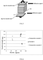
- the evaluation method of the tensile strength of the dehumidifying member will be described with reference to FIG. 5 .
- the tensile strength was evaluated in the following procedure.
- the tensile strength was evaluated for three test samples.
- FIG. 6 illustrates the evaluation results.
- the mean value of the tensile strength was 24.3 kPa.
- a silica gel slurry solution was used instead of the sodium silicate solution of Example 1. After submerged in the silica gel slurry solution whose solid content concentration was adjusted so that the density of the fabricated dehumidifying member becomes substantially the same as that in Example 1, the member was dried at 150 °C and then burned at 500 °C for 1 hour, and thereby the dehumidifying member of Comparative example 1 was fabricated. The tensile strength of the fabricated dehumidifying member was evaluated in the same procedure as in Example 1. FIG. 6 illustrates the evaluation result. The mean value of the tensile strength was 9.6 kPa.
- Example 2 The honeycomb structure fabricated in Example 1 (not submerged in the sodium silicate solution) was used for Comparative example 2.
- the tensile strength of Comparative example 2 was evaluated in the same procedure as in Example 1.
- FIG. 6 illustrates the evaluation result.
- the mean value of the tensile strength was 18.6 kPa.
- the tensile strength is improved by covering the periphery of the adhesive agent of the honeycomb structure with the synthesized silica gel.
- the reason therefor is considered that the synthesized silica gel formed on the air hole side from the adhesion part of the honeycomb structure increases the adhesion area of the contact part and thus achieves the adhesion effect.
- the dehumidifying member fabricated by the manufacturing method of submerging the honeycomb structure in the silica gel slurry disclosed in Patent Literature 2 had a lower tensile strength than the honeycomb structure. In the manufacturing method disclosed in Patent Literature 2, it is difficult to increase the amount of carried silica gel.
- a burning step is performed to improve the dehumidifying performance of the fabricated dehumidifying member.
- the tensile strength of the honeycomb structure is significantly reduced by the burning step in relation to the tensile strength in the manufacturing method of Patent Literature 2.
- the reason for the reduction in the tensile strength is considered that the organic component of the adhesive agent or the like was burned off by the burning step.
- a dehumidifying member was fabricated in the same procedure as in Example 1 except that mixed paper was used instead of glass paper, and the tensile strength was evaluated.
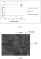
- FIG. 7 illustrates the evaluation result.
- the mean value of the tensile strength was 46.8 kPa.
- a dehumidifying member was fabricated in the same procedure as in Comparative example 1 except that mixed paper was used instead of glass paper, and the tensile strength was evaluated.
- FIG. 7 illustrates the evaluation result.
- the mean value of the tensile strength was 2.1 kPa.
- Example 4 The honeycomb structure with mixed paper fabricated in Example 2 (not submerged in the sodium silicate solution) was used for Comparative example 4.
- the tensile strength of Comparative example 4 was evaluated in the same procedure as in Example 1.
- FIG. 7 illustrates the evaluation result.
- the mean value of the tensile strength was 8.7 kPa.
- the tensile strength is improved by covering the periphery of the adhesive agent of the honeycomb structure with the synthesized silica gel.
- covering the periphery of the adhesive agent with silica gel increased the tensile strength by 1.3 times.
- covering the periphery of the adhesive agent with silica gel increased the tensile strength by 5.4 times. That is, from the honeycomb structure fabricated by using the adhesive agent, the tensile strength was increased much more when mixed paper was used as the base material than when glass paper was used as the base material.
- FIG. 8 illustrates SEM photographs of the surface of the mixed paper. As illustrated in FIG. 8 , it was confirmed that, in the mixed paper, silica gel was carried in space between fibers in a porous manner.
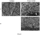
- the synthesized silica gel had a very smooth surface (less voids). Further, as illustrated in the SEM photograph of the cross section in FIG. 9A , it was confirmed that, in the dehumidifying member fabricated in Example 2, the synthesized silica gel was laminated (the part pointed by the arrow in the photograph of FIG. 9B ) on the surface of the porous silica gel included in the mixed paper (the part surrounded by the circle in the photograph of FIG. 9B ).
- Example 1 when tensile force is applied to the honeycomb structure, the planar base material and the corrugated base material of the honeycomb structure are likely to distribute the tensile force, and as a result, distortion is less likely to be concentrated at the contact part 23.
- Example 1 as illustrated in FIG. 9B , since a part from the surface to inside of the glass paper is integrally formed of the synthesized silica gel, force is less likely to be distributed when tensile force is applied. It is therefore considered that, since applied tensile force is concentrated on the contact part 23, the tensile strength was reduced compared to the case of mixed paper.
- the synthesized silica gel achieves an advantageous effect of notably improving the adhesion function at the contact part of a honeycomb structure in addition to the dehumidifying function of silica gel. That is, it was confirmed that two different advantageous effects are achieved.
- the tensile strength of the honeycomb structure formed from mixed paper is lower than the tensile strength of the honeycomb structure formed from glass paper (see Comparative examples 2 and 4). It was also confirmed however that, since the synthesized silica gel exhibits an adhesion effect to both the porous silica gel and the fibers included in mixed paper, the adhesion function of the synthesized silica gel is significantly superior when mixed paper is used as the base material forming a honeycomb structure.
- the tensile strength of a dehumidifying member is improved. Therefore, the disclosure is useful for manufacturers of dehumidifying devices and the manufacturing industry requiring dehumidified air.
Landscapes
- Chemical & Material Sciences (AREA)
- Organic Chemistry (AREA)
- Analytical Chemistry (AREA)
- Chemical Kinetics & Catalysis (AREA)
- Inorganic Chemistry (AREA)
- Dispersion Chemistry (AREA)
- Engineering & Computer Science (AREA)
- Oil, Petroleum & Natural Gas (AREA)
- General Chemical & Material Sciences (AREA)
- General Engineering & Computer Science (AREA)
- Mechanical Engineering (AREA)
- Combustion & Propulsion (AREA)
- Drying Of Gases (AREA)
- Solid-Sorbent Or Filter-Aiding Compositions (AREA)
- Silicon Compounds (AREA)
- Paper (AREA)
Abstract
Description
- The disclosure of the present application relates to a dehumidifying member, a dehumidifying rotor, and a manufacturing method of a dehumidifying member.
- Some manufacturing sites such as a factory may need dry air from which moisture has been removed. For example, in a semiconductor manufacturing factory, there is an increased demand for dry air from which moisture, which may cause oxidation, has been removed as much as possible. As a device for supplying dry air, a dehumidifying device equipped with a dehumidifying rotor that carries silica gel or zeolite in a honeycomb structure is known (see Patent Literature 1).
- The dehumidifying device equipped with a dehumidifying rotor is divided into a treatment zone and a reproduction zone as illustrated in
FIG. 6 ofPatent Literature 1, for example, and the dehumidifying rotor is rotated to move through the treatment zone, the reproduction zone, the treatment zone, the reproduction zone, ... sequentially at a predetermined speed. Further, when located in the treatment zone, the dehumidifying rotor adsorbs moisture from high humidity air, and when located in the reproduction zone, the dehumidifying rotor releases moisture adsorbed to the dehumidifying rotor and thereby reproduces the dehumidifying function of the dehumidifying rotor. Such repetition of moisture absorption to the dehumidifying rotor and moisture removal from the dehumidifying rotor enables a continuous operation of the dehumidifying device. - As a manufacturing method of a dehumidifying rotor, a method including the following steps is disclosed in
Patent Literature 1, for example. - (1) A paper sheet is fed between a pair of forming rollers having a desired teeth shape, and thereby a wave-shaped paper sheet is formed.
- (2) A waterglass adhesive agent is applied to one side of the wave top portions of the wave-shaped paper sheet, the wave-shaped paper sheet is then adhered to a porous paper sheet, and subsequently, the adhered paper sheets are wound while the waterglass adhesive agent is applied to the other side of the wave top portion of the wave-shaped sheet, and thereby a cylindrical molded body having honeycomb structure is obtained.
- (3) The molded body is submerged in an aqueous solution of waterglass, subjected to drying and acid treatment, and thereby silica gel is deposited onto the molded body.
- Further,
Patent Literature 2 discloses another manufacturing method of a dehumidifying rotor including the following steps. - (1) First, a honeycomb structure is fabricated.
- (2) The fabricated honeycomb structure is impregnated with slurry containing silica gel, dried, then burned, and thereby a honeycomb structure carrying silica gel is formed.
-
- Patent Literature 1:
Japanese Patent Application Laid-Open No. S61-252497 - Patent Literature 2:
Japanese Patent No. 4958459 - Either an increase in scale of a factory or an increase in required dehumidifying performance may require an increase in size of a dehumidifying rotor. In a case of a larger dehumidifying rotor, compression force works on the upper side in the perpendicular direction because of the weight of the dehumidifying rotor when viewed from the center of rotation of the dehumidifying rotor. On the other hand, force in a direction in which an adhesion portion of the honeycomb structure is peeled off works on the lower side in the perpendicular direction when viewed from the center of rotation of the dehumidifying rotor because of the weight of the dehumidifying rotor.
- Further, when the dehumidifying rotor is incorporated in a dehumidifying device, a dehumidifying member may be fixed by a sheet metal. In such a case, if the dehumidifying rotor is expanded or contracted by moisture adsorption and desorption, a tensile stress may occur at the adhesion portion of the honeycomb structure causing peeling off. Thus, a more robust adhesion portion of the honeycomb structure is desired.
- However, the dehumidifying rotor disclosed in
Patent Literature 1 increases the amount of silica gel deposition and thus is manufactured by steps of (1) using a paper sheet having an extremely small density of inorganic fibers forming the honeycomb structure to impregnate waterglass into deep inside of the paper sheet, (2) using waterglass as an adhesive agent used for forming the honeycomb structure, and (3) gelating the waterglass into silica gel through acid treatment. Thus, there is a problem of there being no choice other than waterglass for the adhesive agent when it is intended to increase the amount of silica gel deposition on the dehumidifying rotor. - In contrast, the dehumidifying rotor disclosed in
Patent Literature 2 is manufactured by impregnating a honeycomb structure with silica gel slurry, and drying, then heating, and burning the impregnated honeycomb structure. However, the inventors have newly found a problem that the tensile strength of the honeycomb structure is very low, that is, interlayer peeling in the honeycomb structure is likely to occur in the manufacturing method of the dehumidifying rotor disclosed inPatent Literature 2, as illustrated in a comparative example described later. - The disclosure of the present application has been made in order to solve the problem described above, and according to a thorough study, it has been newly found that it is possible to provide a dehumidifying member having a high tensile strength by forming a contact part between a planar base material and a corrugated base material, which form a honeycomb structure, by using an adhesion part adhered with an adhesive agent and using silica gel formed on an air hole side from the adhesion part.
- That is, an object of the disclosure of the present application is to provide a dehumidifying member having a high tensile strength, a dehumidifying rotor including the same, and a manufacturing method of the dehumidifying member.
- The disclosure of the present application relates to a dehumidifying member, a dehumidifying rotor, and a manufacturing method of a dehumidifying member illustrated below.
- (1) A dehumidifying member comprising a honeycomb structure,
- wherein the honeycomb structure includes
- a planar base material and a corrugated base material, and
- a contact part where a wave top portion of the corrugated base material and the planar base material are in contact with each other, and
- an air hole,
- wherein the contact part includes
- an adhesion part adhered with an adhesive agent, and
- silica gel formed on the air hole side from the contact part, and
- wherein a component forming the adhesive agent differs from a component of the silica gel formed on the air hole side from the adhesion part.
- (2) The dehumidifying member according to (1) above, wherein the planar base material and/or the corrugated base material is mixed paper.
- (3) The dehumidifying member according to (2) above,
- wherein the mixed paper contains silica gel in space between fibers, and
- wherein the volume of voids in the silica gel contained in the mixed paper is larger than the volume of voids of silica gel formed on the air hole side from the adhesion part.
- (4) The dehumidifying member according to any one of (1) to (3) above, wherein the adhesive agent contains an organic component.
- (5) A dehumidifying rotor including the dehumidifying member according to any one of (1) to (3) above.
- (6) A dehumidifying rotor including the dehumidifying member according to (4) above.
- (7) A manufacturing method of a dehumidifying member, the manufacturing method comprising:
- a carrying step of causing a honeycomb structure to carry a sodium silicate solution; and
- a silica gel synthesis step of synthesizing silica gel by performing acid treatment on sodium silicate carried in the honeycomb structure by the carrying step,
- wherein the honeycomb structure includes
- a planar base material and a corrugated base material,
- an adhesion part that adheres a wave top portion of the corrugated base material and the planar base material to each other, and
- an air hole.
- (8) The manufacturing method according to (7) above, wherein the planar base material and/or the corrugated base material is mixed paper.
- (9) The manufacturing method according to (7) or (8), wherein the adhesive agent contains an organic component.
- According to the disclosure of the present application, it is possible to provide a dehumidifying member having a higher tensile strength than a conventional dehumidifying member.
-
- [
FIG. 1] FIG. 1 is a perspective view illustrating an overview of a dehumidifying rotor and dehumidifying members according to a first embodiment. - [
FIG. 2] FIG. 2 is a diagram illustrating an overview of a honeycomb structure when the dehumidifying member is viewed in a direction of the center axis of rotation of the dehumidifying rotor ofFIG. 1 . - [
FIG. 3] FIG. 3 is a schematic enlarged sectional view of a contact part of the honeycomb structure. - [
FIG. 4] FIG. 4 is a perspective view illustrating an overview of a dehumidifying member according to a third embodiment. - [
FIG. 5] FIG. 5 is a schematic diagram illustrating an evaluation method of the tensile strength of a dehumidifying member. - [
FIG. 6] FIG. 6 is a graph illustrating measurement results for the tensile strength of dehumidifying members fabricated in Example 1 and Comparative example 1 and a honeycomb structure fabricated in Comparative example 2. - [
FIG. 7] FIG. 7 is a graph illustrating measurement results for the tensile strength of dehumidifying members fabricated in Example 2 and Comparative example 3 and a honeycomb structure fabricated in Comparative example 4. - [
FIG. 8] FIG. 8 is a photograph substitute for a drawing, which is a SEM photograph of the surface of mixed paper. - [
FIG. 9] FIG. 9 are photographs substitute for a drawing,FIG. 9A represent SEM photographs of the surface and a cross section of mixed paper forming a honeycomb structure of the dehumidifying member fabricated in Example 2, andFIG. 9B is a SEM photograph of a cross section of glass paper forming a honeycomb structure of the dehumidifying member fabricated in Example 1. - A dehumidifying member, a dehumidifying rotor, and a manufacturing method of a dehumidifying member disclosed in the present application will be described below in detail.
- The dehumidifying member according to a first embodiment will be described with reference to
FIG. 1 to FIG. 3 .FIG. 1 is a perspective view illustrating the overview of adehumidifying rotor 10 anddehumidifying members 1.FIG. 2 is a diagram illustrating the overview of ahoneycomb structure 2 when the dehumidifyingmember 1 is viewed in the Z direction that is the center axis of rotation of thedehumidifying rotor 10 ofFIG. 1 .FIG. 3 is a schematic enlarged sectional view of acontact part 23 of thehoneycomb structure 2. - The dehumidifying
member 1 according to the first embodiment is one of sections divided into one or more from the dehumidifyingrotor 10. Although an example in which threedehumidifying members 1 are combined to form thedehumidifying rotor 10 is illustrated in the example illustrated inFIG. 1 , any number ofdehumidifying members 1 forming thedehumidifying rotor 10 may be employed. Further, the dehumidifyingrotor 10 may be formed of asingle dehumidifying member 1. - The dehumidifying
member 1 has thehoneycomb structure 2. Thehoneycomb structure 2 includesplanar base materials 21,corrugated base materials 22,contact parts 23 wherewave top portions 22a of eachcorrugated base material 22 and eachplanar base material 21 are in contact with each other, and air holes 24. Eachcontact part 23 includes an adhesion part 23a adhered with an adhesive agent andsilica gel 23b formed on the air hole side from the adhesion part 23a. - While described later in detail with a manufacturing method described below, the dehumidifying
member 1 is made by, first, manufacturing thehoneycomb structure 2 including theadhesion parts 23, subsequently causing thehoneycomb structure 2 to carry a sodium silicate solution, and then synthesizing thesilica gel 23b from sodium silicate through acid treatment (hereafter, silica gel synthesized from sodium silicate may be referred to as "synthesized silica gel") . Once thehoneycomb structure 2 is submerged in the sodium silicate solution, the sodium silicate solution is filled in space S formed by the adhesion part 23a, theplanar base material 21, and thecorrugated base material 22. Thus, the adhesion part 23a is covered with the synthesizedsilica gel 23b. Note that, in the manufacturing method disclosed in the present specification, the synthesizedsilica gel 23b is formed entirely around theplanar base material 21 and thecorrugated base material 22 that form thehoneycomb structure 2. In the present specification, as illustrated inFIG. 3 , thesilica gel 23b included in thecontact part 23 means the synthesizedsilica gel 23b on the adhesion part 23a side from the boundary B between the synthesizedsilica gel 23b formed around theplanar base material 21 and the synthesizedsilica gel 23b formed around thecorrugated base material 22. In other words, thesilica gel 23b included in thecontact part 23 may refer to, in the synthesizedsilica gel 23b, a portion which is in contact with both theplanar base material 21 and thecorrugated base material 22. - For the
planar base material 21 and thecorrugated base material 22 of the dehumidifyingmember 1 according to the first embodiment, any fibrous base material known in this technical field can be used. Specific examples of the fiber base material may be, for example, inorganic fiber such as silica and alumina fiber, silica fiber, alumina fiber, mullite fiber, glass fiber, rock wool fiber, carbon fiber, or the like; or organic fiber such as polyethylene fiber, polypropylene fiber, nylon fiber, polyester fiber, polyvinyl alcohol fiber, polyethylene terephthalate fiber, aramid fiber, pulp fiber, rayon fiber, or the like. Further, each of these fibers may be of a single type or a combination of two or more types. Note that the fibers described above are mere examples, and the embodiment is not limited to these fibers. Further, theplanar base material 21 and thecorrugated base material 22 may be made by using the same type of fiber or using different types of fiber. - With respect to the fiber of the dehumidifying
member 1 according to the first embodiment, if the density thereof is too low, the strength of the honeycomb structure will decrease, and if the density thereof is too high, the amount of silica gel carried between fibers will decrease. Therefore, the density of fibers can be selected as appropriate taking the strength, the amount of the honeycomb structure (the amount of moisture adsorption), or the like into consideration. The density of fibers of the dehumidifyingmember 1 according to the first embodiment may be, for example, 0.05 to 0.5 g/cm3, preferably 0.08 to 0.3 g/cm3, more preferably 0.1 to 0.2 g/cm3, or the like. - The adhesive agent forming the
adhesion part 23 is not particularly limited as long as it can adhere theplanar base material 21 and thewave top portion 22a of thecorrugated base material 22 to each other. For example, an inorganic adhesive agent or an organic adhesive agent may be used. Examples of the inorganic adhesive agent may be a silica-based adhesive agent, water glass, or the like. Further, the organic adhesive agent may be an acrylic resin-based adhesive agent, an acrylic resin emulsion adhesive agent, an α-olefine-based adhesive agent, an urethan resin-based adhesive agent, an urethan resin emulsion adhesive agent, an ether-based cellulose, an ethylene-vinyl acetate resin emulsion adhesive agent, an epoxy resin-based adhesive agent, an epoxy resin emulsion adhesive agent, a vinyl chloride resin solvent-based adhesive agent, a chloroprene rubber-based adhesive agent, a vinyl acetate resin emulsion adhesive agent, a cyanoacrylate-based adhesive agent, a silicone-based adhesive agent, an aqueous polymer-isocyanate-based adhesive agent, a styrene-butadiene rubber solution-based adhesive agent, a styrene-butadiene rubber-based latex adhesive agent, a nytril rubber-based adhesive agent, a polyimide-based adhesive agent, a polyvinyl alcohol based adhesive agent, a starch-based adhesive agent, a natural rubber-based adhesive agent, or the like. - The adhesive agent can be selected as appropriate in accordance with the material of the
planar base material 21 and thecorrugated base material 22. Further, the adhesive agent may be used in combination of two or more types selected from inorganic adhesive agents and organic adhesive agents. Further, a tackifier, a plasticizer, a curing agent, a cross-linking agent, a diluent, a filler, a thickener, a pigment, an anti-aging agent, an antioxidant, an antifoaming agent, a flame retardant, a preservative, a dispersant, a wetting agent, a hydrophilic agent, or the like may be added to the adhesive agent, if necessary. - The sodium silicate solution used for synthesizing the
silica gel 23b is made by dissolving sodium silicate in water and is also referred to as "water glass". The sodium silicate solution can be fabricated by dissolving commercially available sodium silicate in water. If the concentration of the sodium silicate solution is too low, the amount thereof that can be carried in thehoneycomb structure 2 by a single carrying step will be small. In contrast, if the concentration of the sodium silicate solution is too high, the air holes 24 of thehoneycomb structure 2 may be clogged. Therefore, the concentration of the sodium silicate may be suitably set so that a desired amount thereof can be carried and the air holes 24 are not clogged. The concentration of the sodium silicate solution may be, for example, 20 to 50% by mass, preferably 25 to 45% by mass, and more preferably 30 to 40% by mass. - The dehumidifying
member 1 according to the first embodiment is made by, first, adhering theplanar base materials 21 and thewave top portions 22a of thecorrugated base materials 22 to each other by using an adhesive agent to fabricate thehoneycomb structure 2. Unlike the art ofPatent Literature 2, the dehumidifyingmember 1 according to the first embodiment is not required to be burned. Therefore, an adhesive agent that is relatively susceptible to heat can also be used, and this provides wider choices of types of adhesive agents to be used. - Further, as described in
Patent Literature 1, sodium silicate (water glass) can be used as an adhesive agent. In thedehumidifying member 1 according to the first embodiment, however, an adhesive agent having a high adhesive effect can be selected for the adhesion part 23a. Therefore, the component of the adhesion part 23a adhered with the adhesive agent and the component of the synthesizedsilica gel 23b formed on the air hole side from the adhesion part 23a are different from each other. Note that, in the present specification, components being different means that the component of the entire adhesive agent differs from the component of the synthesizedsilica gel 23b and does not prevent a part of the component of the adhesive agent from being the same as the component of the synthesized silica gel. - Effects obtained due to the different components of the adhesion part 23a adhered with the adhesive agent and the synthesized
silica gel 23b formed on the air hole side from the adhesion part 23a may be an effect of the improved strength of the honeycomb structure, because the adhesive strength is enhanced by the anchor effect by different types of adhesive agents, an effect of cost reduction or added functionality due to improved design flexibility provided by the use of different types of adhesive agents, or the like. In contrast, when sodium silicate is used as the adhesive agent, for example, the adhesive agent deposited and solidified on the adhesion part 23a may be melted in the step of causing a sodium silicate solution to be carried, and a molded body as a dehumidifying member may not be maintained. In such a case, it is considered that the use of a different adhesive agent unsusceptible to a sodium silicate solution as the adhesive agent can provide an effect of preventing the above phenomenon. The adhesive agent unsusceptible to a sodium silicate solution may be, for example, an acrylic resin emulsion adhesive agent, an ethylene-vinyl acetate resin emulsion adhesive agent, or the like. - Further, another effect obtained due to the different components of the adhesion part 23a adhered with the adhesive agent and the synthesized
silica gel 23b formed on the air hole side from the adhesion part 23a may be in that a survey of the distribution or the amount of deposition or the like of the adhesive agent will contribute to analysis of a cause for occurrence of a product failure. - The second embodiment of the dehumidifying
member 1 will be described. The dehumidifyingmember 1 according to the second embodiment differs from the dehumidifyingmember 1 according to the first embodiment in that theplanar base material 21 and/or thecorrugated base material 22 is mixed paper and, for other features, is the same as the dehumidifyingmember 1 according to the first embodiment. Accordingly, in the second embodiment, features different from those of the first embodiment will be mainly described, and repeated description for the features that have already been described in the first embodiment will be omitted. Thus, even though not explicitly described in the second embodiment, it is apparent that the features that have already been described in the first embodiment can be employed in the second embodiment. - In the present specification, the mixed paper means a sheet-like base material made with hygroscopic particles such as silica gel, zeolite, silica alumina amorphous porous bodies, mesoporous silica, ion exchange resin, polyacrylate resin, alkylene oxide resin, or the like filled in space between fibers of a fibrous base material forming the
planar base material 21 and thecorrugated base material 22 illustrated as an example in the first embodiment. The mixed paper is fabricated by making a fiber solution containing dispersed hygroscopic fine particles into a sheet shape. The type of silica gel can be selected as appropriate in accordance with the purpose. For example, the A-type that is superior in moisture absorbency at a low humidity or the B-type that is superior in moisture absorbency at a high humidity can be selected in accordance with the purpose. Alternatively, silica gel of the A-type and silica gel of the B-type may be mixed. - Note that hygroscopic fine particles contained in mixed paper is in a form in which fine particles are aggregated in space between fibers in a manufacturing process. On the other hand, the synthesized
silica gel 23b formed on the air hole side from the adhesion part 23a is fabricated by performing acid treatment on sodium silicate impregnated into thehoneycomb structure 2. Thus, the volume of voids in the hygroscopic fine particles contained in the mixed paper is larger than the volume of voids in the synthesizedsilica gel 23b formed on the air hole side from the adhesion part 23a. Note that, in the present specification, the term "volume of voids" differs from the specific surface area representing the pore surface area inside a hygroscopic fine particle and means the volume per unit volume of space formed in space between fine particles. The term "volume of voids" can be determined by capturing an image of fine particles by SEM or the like and performing comparison based on the coarseness in appearance. When fine particles are aggregated more randomly, the "volume of voids" will be larger, and the appearance of a SEM image is coarser (fine unevenness is observed). In contrast, when the "volume of voids" is smaller, fine particles are formed more densely, and therefore, the appearance of a SEM image will be smoother. - Further, the "volume of voids" does not mean the volume of space between individual fine particles but means the volume of voids in a region where a predetermined amount of fine particles are aggregated (coarseness or smoothness in the appearance). The region where a predetermined amount of fine particles are aggregated means any region where fine particles viewed from a SEM image are aggregated. Therefore, a crack or the like formed in the surface are not included in the region. In other words, the region does not mean the entire surface observed in a SEM image but just means a portion where fine particles are aggregated.
- Note that the difference between a mass of hygroscopic fine particles contained in mixed paper and the synthesized
silica gel 23b may be expressed by using a term of "surface smoothness", "surface property", or "surface coarseness" instead of "volume of voids". Further, the difference between a mass of hygroscopic fine particles contained in mixed paper and the synthesizedsilica gel 23b viewed from a SEM image may be expressed as follows. - hygroscopic fine particles having an uneven surface where granulocytes are aggregated versus synthesized silica gel having a block shape whose surface is relatively flat.
- hygroscopic fine particles having a rough surface versus synthesized silica gel having a smooth surface.
- The third embodiment of the dehumidifying
member 1 will be described with reference toFIG. 4 . The dehumidifyingmember 1 according to the third embodiment differs from the dehumidifyingmember 1 according to the first and second embodiments in that thehoneycomb structure 2 is formed such that theplanar base materials 21 are laminated with thewave top portions 22a of thecorrugated base material 22 being adhered to respectiveplanar base materials 21, in other words, such that theplanar base materials 21 are substantially parallel to each other and, for other features, is the same as the dehumidifyingmember 1 according to the first and second embodiment. Accordingly, in the third embodiment, features different from those of the first and second embodiments will be mainly described, and repeated description for the features that have already been described in the first and second embodiments will be omitted. Thus, even though not explicitly described in the third embodiment, it is apparent that the features that have already been described in the first and second embodiments can be employed in the third embodiment. - The dehumidifying
member 1 according to the third embodiment can be made by adhering thewave top portions 22a of thecorrugated base material 22 to theplanar base material 21, cutting theplanar base material 21 and thecorrugated base material 22 into a predetermined length, and laminating the cut base materials one on another. The form of lamination may be alternate lamination such as theplanar base material 21, thecorrugated base material 22, theplanar base material 21, and thecorrugated base material 22 in this order. Alternatively, sets of theplanar base material 21, thecorrugated base material 22, and theplanar base material 21 in this order may be fabricated, and theplanar base materials 21 of these sets may be adhered to each other. Further, althoughFIG. 4 illustrates an example of thehoneycomb structure 2 of alternate lamination such that the vent directions of the air holes 24 are each shifted by 90 degrees, the directions in which the air holes 24 are formed may be the same. Note that the same form of lamination applies to the first embodiment and the second embodiment. - An embodiment of the
dehumidifying rotor 10 will be described with reference toFIG. 1 andFIG. 4 . The dehumidifyingrotor 10 can be fabricated by combining thedehumidifying members 1 according to the first and second embodiments. As long as thedehumidifying members 1 according to the first and second embodiments are used, the fabrication procedure of thedehumidifying rotor 10 is not particularly limited. For example,FIG. 1 illustrates an example of fabricating thedehumidifying rotor 10 by (1) winding theplanar base material 21 and thecorrugated base material 22 into a roll while adhering thewave top portions 22a of thecorrugated base material 22 to theplanar base material 21 to manufacture a rotor, (2) dividing the rotor and causing each of the divided rotors to carry a sodium silicate solution, (3) performing acid treatment on sodium silicate to synthesize thesilica gel 23b to fabricate thedehumidifying members 1, and (4) combining the fabricateddehumidifying members 1. Alternatively, the rotor may be used as it stands without being divided in the step of (2) described above. - Further, when the dehumidifying
member 1 according to the third embodiment illustrated inFIG. 4 is used to fabricate thedehumidifying rotor 10, the dehumidifyingmember 1 can be cut into suitable shapes, and the cut members can then be combined. - The manufacturing method of a dehumidifying member includes:
- a carrying step of causing a honeycomb structure to carry a sodium silicate solution; and
- a silica gel synthesis step of synthesizing silica gel by performing acid treatment on sodium silicate carried in the honeycomb structure by the carrying step.
- Since the honeycomb structure and the sodium silicate solution have already been described, the detailed description thereof will be omitted. Acid used in the silica gel synthesis step is not particularly limited as long as silica gel can be synthesized from the sodium silicate solution. The acid may be, for example, sulfuric acid, phosphoric acid, nitric acid, hydrochloric acid, and a metal salt of such acid, for example, an aluminum salt such as aluminum sulfate or aluminum nitrate, a calcium salt such as calcium nitrate or calcium chloride, a magnesium salt such as magnesium sulfate or magnesium chloride, or an iron salt such as iron sulfate or iron nitrate. The acid and the metal salt of the acid listed above may be used alone or may be used in combination. Further, the synthesized
silica gel 23b may be the A-type or may be the B-type. Synthesis can be made to have a desired type in accordance with the purpose by a method of changing the concentration of the acid treatment or the like. Note that, when an aluminum salt is used as acid in synthesis of silica gel from a sodium silicate solution, silica-alumina gel is obtained. In the present specification, when "synthesized silica gel" is referred to, the "synthesized silica gel" encompasses silica gel containing a metal salt derived from acid. - While Examples are provided below to specifically describe the embodiments disclosed in the present application, these Examples are solely provided for the purpose of illustration of the embodiments. These Examples are not intended to limit or restrict the scope of the present invention disclosed in the present application.
- The following products were used as materials. Note that ratios are represented as % by mass.
-
[Table 1] Material Glass paper Mixed paper Silica gel 65% Glass fiber 75% 15% Organic fiber 25% 20% - Note that SYLYSIA 740 (Type A silica gel, Fuji SYLYSIA Chemical LTD.) was used for silica gel. Further, the basis weight (g/cm2) of the fabricated base material was 20 for the glass paper and 83 for the mixed paper, and the thickness (µm) was 101 for the glass paper and 197 for the mixed paper.
-
[Table 2] Material For glass paper For mixed paper Colloidal silica (solid content) 40% 32% Vinyl acetate emulsion (solid content) 8% Acrylic emulsion (solid content) 13% Ion exchange water 52% 55% -
[Table 3] Material Ratio No.2 sodium silicate 89% Ion exchange water 11% -
[Table 4] Material Ratio Aluminum sulfate salt 18% Ion exchange water 82% -
[Table 5] Material Ratio Type A silica gel 24% Colloidal silica (solid content) 7% Ion exchange water 69% - The dehumidifying member was fabricated by the following procedure.
- (1) Glass paper was used as the planar base material and the corrugated base material. The glass paper was corrugate-processed by using an adhesive agent, and the corrugate-processed paper sheet was wound into a spiral shape with an adhesive agent to fabricate a rotor-type honeycomb structure having a diameter of 450 mm, a flute length of 210 mm, and a flute height of 1.9 mm. Note that the flute length means the length of the
wave top portion 22a of the corrugated base material 22 (the thickness of the dehumidifying rotor) (see "L" inFIG. 1 and FIG. 2 ), and the flute height means the distance between thewave top portion 22a and the planar base material 21 (see "H" inFIG. 2 ). - (2) After the fabricated honeycomb structure was submerged in the sodium silicate solution (otherwise, means for spraying or sprinkling by using a spray, a sprinkler, or the like may be employed as carrying means for causing sodium silicate to be carried), the honeycomb structure was taken out of the sodium silicate solution.
- (3) After subjected to air blow, the honeycomb structure carrying the sodium silicate solution was submerged in an acid treatment liquid, and hydrogel of aluminum silicate was produced by a chemical reaction of sodium silicate in the honeycomb structure with aluminum sulfate.
- (4) The honeycomb structure was heated and dried to obtain a dehumidifying member reinforced by silica gel.
- The evaluation method of the tensile strength of the dehumidifying member will be described with reference to
FIG. 5 . The tensile strength was evaluated in the following procedure. - (1) The fabricated dehumidifying member was cut into a cubic shape of 5 cm3 so as to be parallel to the laminating direction, and the cut member was used as a test sample for tensile strength measurement.
- (2) The test sample was dried at 110 °C for 1 hour, the weight was measured by an electronic scale, and the lengths of three sides were measured by a caliper.
- (3) Jigs for tensile test were adhered to the top and the bottom in the laminating direction of the honeycomb structure of the test sample, respectively, by using an epoxy adhesive agent.
- (4) The test sample was attached to a tensile test machine (Shimadzu Corporation, Shimadzu Compact Desktop Testing Machine Ez-LX), a tensile load was continuously added to the test sample at 1 mm/min, and the load at break was found by the minimum unit of 1 N.
- (5) The tensile strength in the laminating direction was found by the following equation.

- The tensile strength was evaluated for three test samples.
FIG. 6 illustrates the evaluation results. The mean value of the tensile strength was 24.3 kPa. - A silica gel slurry solution was used instead of the sodium silicate solution of Example 1. After submerged in the silica gel slurry solution whose solid content concentration was adjusted so that the density of the fabricated dehumidifying member becomes substantially the same as that in Example 1, the member was dried at 150 °C and then burned at 500 °C for 1 hour, and thereby the dehumidifying member of Comparative example 1 was fabricated. The tensile strength of the fabricated dehumidifying member was evaluated in the same procedure as in Example 1.
FIG. 6 illustrates the evaluation result. The mean value of the tensile strength was 9.6 kPa. - The honeycomb structure fabricated in Example 1 (not submerged in the sodium silicate solution) was used for Comparative example 2. The tensile strength of Comparative example 2 was evaluated in the same procedure as in Example 1.
FIG. 6 illustrates the evaluation result. The mean value of the tensile strength was 18.6 kPa. - As illustrated in
FIG. 6 , it was confirmed that the tensile strength is improved by covering the periphery of the adhesive agent of the honeycomb structure with the synthesized silica gel. The reason therefor is considered that the synthesized silica gel formed on the air hole side from the adhesion part of the honeycomb structure increases the adhesion area of the contact part and thus achieves the adhesion effect. In contrast, the dehumidifying member fabricated by the manufacturing method of submerging the honeycomb structure in the silica gel slurry disclosed inPatent Literature 2 had a lower tensile strength than the honeycomb structure. In the manufacturing method disclosed inPatent Literature 2, it is difficult to increase the amount of carried silica gel. Thus, a burning step is performed to improve the dehumidifying performance of the fabricated dehumidifying member. According to the disclosure of the present application, however, it was newly found that the tensile strength of the honeycomb structure is significantly reduced by the burning step in relation to the tensile strength in the manufacturing method ofPatent Literature 2. The reason for the reduction in the tensile strength is considered that the organic component of the adhesive agent or the like was burned off by the burning step. - Further, in the manufacturing method disclosed in
Patent Literature 2, to cause silica gel to be carried in the honeycomb structure, it is required to add colloidal silica having no dehumidifying function into the silica gel slurry. Thus, it is not possible to allow all the fine particles carried in the honeycomb structure to have a dehumidifying function. In contrast, in the dehumidifying member disclosed in the present application, since silica gel is synthesized from a sodium silicate solution, all the fine particles (synthesized silica gel) carried in the honeycomb structure achieve the dehumidifying function. It is therefore possible to improve the dehumidifying performance per unit weight. - A dehumidifying member was fabricated in the same procedure as in Example 1 except that mixed paper was used instead of glass paper, and the tensile strength was evaluated.
FIG. 7 illustrates the evaluation result. The mean value of the tensile strength was 46.8 kPa. - A dehumidifying member was fabricated in the same procedure as in Comparative example 1 except that mixed paper was used instead of glass paper, and the tensile strength was evaluated.
FIG. 7 illustrates the evaluation result. The mean value of the tensile strength was 2.1 kPa. - The honeycomb structure with mixed paper fabricated in Example 2 (not submerged in the sodium silicate solution) was used for Comparative example 4. The tensile strength of Comparative example 4 was evaluated in the same procedure as in Example 1.
FIG. 7 illustrates the evaluation result. The mean value of the tensile strength was 8.7 kPa. - As illustrated in
FIG. 7 , it was confirmed that the tensile strength is improved by covering the periphery of the adhesive agent of the honeycomb structure with the synthesized silica gel. Note that, in comparison between Example 1 and Comparative example 2, covering the periphery of the adhesive agent with silica gel increased the tensile strength by 1.3 times. On the other hand, in comparison between Example 2 and Comparative example 4, covering the periphery of the adhesive agent with silica gel increased the tensile strength by 5.4 times. That is, from the honeycomb structure fabricated by using the adhesive agent, the tensile strength was increased much more when mixed paper was used as the base material than when glass paper was used as the base material. - To elucidate the reason why the tensile strength is significantly increased compared to the honeycomb structure when the mixed paper is used as the base material, the surface of the base material and a cross section of the base material were captured by using SEM. First,
FIG. 8 illustrates SEM photographs of the surface of the mixed paper. As illustrated inFIG. 8 , it was confirmed that, in the mixed paper, silica gel was carried in space between fibers in a porous manner. - Next, SEM photographs of the surface and a cross section of the mixed paper forming the honeycomb structure of the dehumidifying member fabricated in Example 2 (
FIG. 9A ) and a SEM photograph of a cross section of glass paper forming the honeycomb structure of the dehumidifying member fabricated in Example 1 (FIG. 9B ) are illustrated. - As illustrated in the SEM photographs of the surface in
FIG. 9A , it was confirmed that the synthesized silica gel had a very smooth surface (less voids). Further, as illustrated in the SEM photograph of the cross section inFIG. 9A , it was confirmed that, in the dehumidifying member fabricated in Example 2, the synthesized silica gel was laminated (the part pointed by the arrow in the photograph ofFIG. 9B ) on the surface of the porous silica gel included in the mixed paper (the part surrounded by the circle in the photograph ofFIG. 9B ). - In contrast, as illustrated in the SEM photograph of the cross section in
FIG. 9B , it was confirmed that, in the dehumidifying member fabricated in Example 1, silica gel synthesized by performing acid treatment on a sodium silicate solution from the surface to inside of the glass paper was integrally synthesized. - The following reasons are considered as to what caused the tensile strength of the dehumidifying member fabricated in Example 2 to be significantly higher than the dehumidifying member of Example 1.
- (1) First, consideration is made on a part near the contact part of the honeycomb structure. As described above, the synthesized silica gel formed on the air hole side from the adhesion part increases the adhesion area of the contact part. The silica gel inside mixed paper is porous (with much unevenness). Thus, a sodium silicate solution enters space in the porous silica gel, a part of the synthesized silica gel is incorporated into the porous silica gel by the synthesis step, and this increases the integrity of the porous silica gel inside the mixed paper and the outside synthesized silica gel, that is, increases the adhesiveness between the porous silica gel and the outside synthesized silica gel. It is therefore considered that the synthesized silica gel of the space S part in
FIG. 3 achieves the adhesion enhancement effect in cooperation with the porous silica gel included inside theplanar base material 21 and thecorrugated base material 22 in addition to the increase in the adhesion area of the contact part. - (2) Next, consideration is made on the planar base material and the corrugated base material as a whole. In the honeycomb structure of Example 2, only the surface of mixed paper is covered with dense synthesized silica gel while the porous portion inside the mixed paper is maintained. Thus, since the rigidity differs between the outside and the inside of the mixed paper that is the base material forming the honeycomb structure, force is likely to be distributed when tensile force is applied.
- In other words, when tensile force is applied to the honeycomb structure, the planar base material and the corrugated base material of the honeycomb structure are likely to distribute the tensile force, and as a result, distortion is less likely to be concentrated at the
contact part 23. In contrast, in Example 1, as illustrated inFIG. 9B , since a part from the surface to inside of the glass paper is integrally formed of the synthesized silica gel, force is less likely to be distributed when tensile force is applied. It is therefore considered that, since applied tensile force is concentrated on thecontact part 23, the tensile strength was reduced compared to the case of mixed paper. - In accordance with the above results, when a dehumidifying member is manufactured by the manufacturing method of a dehumidifying member disclosed in the present application, since a honeycomb structure is first fabricated and silica gel is then synthesized, choices of adhesive agents used for forming the honeycomb structure are increased. In particular, since the dehumidifying member disclosed in
Patent Literature 2 intends to improve the dehumidifying performance with a burning step at about 500 °C, it is not possible to use an adhesive agent whose combustion temperature is lower than 500 °C. For the dehumidifying member disclosed in the present application, however, it is possible to use even an adhesive agent having a lower combustion temperature. - Further, the synthesized silica gel achieves an advantageous effect of notably improving the adhesion function at the contact part of a honeycomb structure in addition to the dehumidifying function of silica gel. That is, it was confirmed that two different advantageous effects are achieved. The tensile strength of the honeycomb structure formed from mixed paper is lower than the tensile strength of the honeycomb structure formed from glass paper (see Comparative examples 2 and 4). It was also confirmed however that, since the synthesized silica gel exhibits an adhesion effect to both the porous silica gel and the fibers included in mixed paper, the adhesion function of the synthesized silica gel is significantly superior when mixed paper is used as the base material forming a honeycomb structure.
- According to the disclosure of the present application, the tensile strength of a dehumidifying member is improved. Therefore, the disclosure is useful for manufacturers of dehumidifying devices and the manufacturing industry requiring dehumidified air.
-
- 1
- dehumidifying member
- 2
- honeycomb structure
- 21
- planar base material
- 22
- corrugated base material
- 22a
- wave top portion
- 23
- contact part
- 23a
- adhesion part
- 23b
- synthesized silica gel
- 24
- air hole
- 10
- dehumidifying rotor
- B
- boundary
- H
- flute height
- L
- flute length
- S
- space
- Z
- center axis of rotation of a dehumidifying rotor
Claims (9)
- A dehumidifying member comprising a honeycomb structure,wherein the honeycomb structure includesa planar base material and a corrugated base material, anda contact part where a wave top portion of the corrugated base material and the planar base material are in contact with each other, andan air hole,wherein the contact part includesan adhesion part adhered with an adhesive agent, andsilica gel formed on the air hole side from the contact part, andwherein a component forming the adhesive agent differs from a component of the silica gel formed on the air hole side from the adhesion part.
- The dehumidifying member according to claim 1, wherein the planar base material and/or the corrugated base material is mixed paper.
- The dehumidifying member according to claim 2, wherein the mixed paper contains silica gel in space between fibers, and
wherein the volume of voids in the silica gel contained in the mixed paper is larger than the volume of voids of silica gel formed on the air hole side from the adhesion part. - The dehumidifying member according to any one of claims 1 to 3, wherein the adhesive agent contains an organic component.
- A dehumidifying rotor including the dehumidifying member according to any one of claims 1 to 3.
- A dehumidifying rotor including the dehumidifying member according to claim 4.
- A manufacturing method of a dehumidifying member, the manufacturing method comprising:a carrying step of causing a honeycomb structure to carry a sodium silicate solution; anda silica gel synthesis step of synthesizing silica gel by performing acid treatment on sodium silicate carried in the honeycomb structure by the carrying step,wherein the honeycomb structure includesa planar base material and a corrugated base material,an adhesion part that adheres a wave top portion of the corrugated base material and the planar base material to each other, andan air hole.
- The manufacturing method according to claim 7, wherein the planar base material and/or the corrugated base material is mixed paper.
- The manufacturing method according to claim 7 or 8, wherein the adhesive agent contains an organic component.
Applications Claiming Priority (2)
| Application Number | Priority Date | Filing Date | Title |
|---|---|---|---|
| JP2020088096A JP6918183B1 (en) | 2020-05-20 | 2020-05-20 | Dehumidifying member, dehumidifying rotor, and manufacturing method of dehumidifying member |
| PCT/JP2021/018770 WO2021235429A1 (en) | 2020-05-20 | 2021-05-18 | Dehumidification member, dehumidification rotor, and method for producing dehumidification member |
Publications (2)
| Publication Number | Publication Date |
|---|---|
| EP4155269A1 true EP4155269A1 (en) | 2023-03-29 |
| EP4155269A4 EP4155269A4 (en) | 2024-06-12 |
Family
ID=77172717
Family Applications (1)
| Application Number | Title | Priority Date | Filing Date |
|---|---|---|---|
| EP21808126.3A Pending EP4155269A4 (en) | 2020-05-20 | 2021-05-18 | DEHUMIDIFYING ELEMENT, DEHUMIDIFYING ROTOR AND PRODUCTION METHOD OF DEHUMIDIFYING ELEMENT |
Country Status (5)
| Country | Link |
|---|---|
| US (1) | US12292210B2 (en) |
| EP (1) | EP4155269A4 (en) |
| JP (1) | JP6918183B1 (en) |
| CN (1) | CN115485053B (en) |
| WO (1) | WO2021235429A1 (en) |
Families Citing this family (3)
| Publication number | Priority date | Publication date | Assignee | Title |
|---|---|---|---|---|
| WO2025263625A1 (en) * | 2024-06-20 | 2025-12-26 | 東洋紡エムシー株式会社 | Adsorption sheet, corrugated sheet, corrugated laminate, adsorption element, and dehumidifier |
| WO2025263624A1 (en) * | 2024-06-20 | 2025-12-26 | 東洋紡エムシー株式会社 | Adsorption sheet, step-formed sheet, step-formed laminate, adsorption element, and dehumidifier |
| WO2025263628A1 (en) * | 2024-06-20 | 2025-12-26 | 東洋紡エムシー株式会社 | Step-processed laminate, adsorption element, and dehumidifier |
Family Cites Families (11)
| Publication number | Priority date | Publication date | Assignee | Title |
|---|---|---|---|---|
| JPS61252497A (en) | 1985-04-22 | 1986-11-10 | Seibu Giken:Kk | Manufacture of element for dehumidification and total heat exchange |
| JP2579767B2 (en) * | 1987-06-10 | 1997-02-12 | 株式会社 西部技研 | Ultra-low concentration gas adsorption element and gas adsorption removal device |
| US5435958A (en) * | 1993-08-02 | 1995-07-25 | Munters Corporation | Method for making a humidity exchanger medium |
| JP2001149735A (en) * | 1999-11-25 | 2001-06-05 | Ebara Corp | Functional element for dehumidifying or heat exchanging and method of manufacturing the same |
| JP2002046198A (en) | 2000-08-03 | 2002-02-12 | Nichias Corp | Honeycomb structure and manufacturing method thereof |
| JP3874187B2 (en) * | 2003-01-07 | 2007-01-31 | 東洋紡績株式会社 | Dehumidifying element and dehumidifying device |
| JP2005046791A (en) | 2003-07-31 | 2005-02-24 | Nichias Corp | Chemical filter and manufacturing method thereof |
| JP2006205122A (en) | 2005-01-31 | 2006-08-10 | Nippon Zeon Co Ltd | Dehumidified molded body and dehumidified composite molded body |
| JP4958459B2 (en) * | 2006-03-29 | 2012-06-20 | ニチアス株式会社 | Manufacturing method of dehumidifying rotor |
| JP5232517B2 (en) * | 2008-03-28 | 2013-07-10 | ニチアス株式会社 | Silcagel, production method thereof, silica gel-supported paper and silica gel element |
| JP6866895B2 (en) | 2016-10-24 | 2021-04-28 | 王子ホールディングス株式会社 | Inorganic fiber sheet, honeycomb molded product and honeycomb filter |
-
2020
- 2020-05-20 JP JP2020088096A patent/JP6918183B1/en active Active
-
2021
- 2021-05-18 WO PCT/JP2021/018770 patent/WO2021235429A1/en not_active Ceased
- 2021-05-18 EP EP21808126.3A patent/EP4155269A4/en active Pending
- 2021-05-18 US US17/999,035 patent/US12292210B2/en active Active
- 2021-05-18 CN CN202180031305.7A patent/CN115485053B/en active Active
Also Published As
| Publication number | Publication date |
|---|---|
| US20230175713A1 (en) | 2023-06-08 |
| US12292210B2 (en) | 2025-05-06 |
| CN115485053B (en) | 2025-05-13 |
| JP2021181072A (en) | 2021-11-25 |
| WO2021235429A1 (en) | 2021-11-25 |
| CN115485053A (en) | 2022-12-16 |
| JP6918183B1 (en) | 2021-08-11 |
| EP4155269A4 (en) | 2024-06-12 |
Similar Documents
| Publication | Publication Date | Title |
|---|---|---|
| US12292210B2 (en) | Dehumidifying member, dehumidifying rotor, and manufacturing method of dehumidifying member | |
| JPH01293136A (en) | Manufacturing method of activated carbon supported honeycomb structure | |
| TWI358316B (en) | Chemical filter | |
| JP2009073731A (en) | Method for producing polymer-coated airgel, airgel produced thereby, and heat insulating material including the airgel | |
| JPS61252497A (en) | Manufacture of element for dehumidification and total heat exchange | |
| KR101189375B1 (en) | Sheet for air filter, method of manufacturing the same, and air filter | |
| US5683532A (en) | Method of manufacturing an active silica gel honeycomb adsorbing body usable in an atmosphere having 100% relative humidity | |
| TWI410268B (en) | Chemical filter and method for manufacturing same | |
| JPS61101228A (en) | Preparation of humidity exchange element | |
| TWI316870B (en) | Method for manufacturing chemical filter | |
| JP2009234878A (en) | Silica gel, production method thereof, paper carrying the silica gel and silica gel element | |
| CN116272909A (en) | Body material of a rotary dehumidifier and its preparation method | |
| JP6228571B2 (en) | Sound-absorbing building material and manufacturing method thereof | |
| CN205145916U (en) | Honeycomb ceramics in trapezoidal pore | |
| JP2001219022A (en) | NOx removal filter, method of manufacturing the same, and air conditioner | |
| JP3862161B2 (en) | Adsorption sheet manufacturing method and adsorbing element manufacturing method using the same | |
| WO2025013602A1 (en) | Composite sheet | |
| JP2024057201A (en) | Adsorption member, adsorption rotor, and their manufacturing method | |
| JP4932320B2 (en) | Adsorbing member with excellent adsorption / desorption performance and manufacturing method thereof | |
| JP2012200644A (en) | Sheet for dehumidification | |
| JP2002228382A (en) | Heat exchanger | |
| JP2012170832A (en) | Corrugated sheet, and adsorbing element | |
| JPH0116507Y2 (en) | ||
| WO2025263628A1 (en) | Step-processed laminate, adsorption element, and dehumidifier | |
| JP2005046792A (en) | Manufacturing method of chemical filter |
Legal Events
| Date | Code | Title | Description |
|---|---|---|---|
| STAA | Information on the status of an ep patent application or granted ep patent |
Free format text: STATUS: THE INTERNATIONAL PUBLICATION HAS BEEN MADE |
|
| PUAI | Public reference made under article 153(3) epc to a published international application that has entered the european phase |
Free format text: ORIGINAL CODE: 0009012 |
|
| STAA | Information on the status of an ep patent application or granted ep patent |
Free format text: STATUS: REQUEST FOR EXAMINATION WAS MADE |
|
| 17P | Request for examination filed |
Effective date: 20221202 |
|
| AK | Designated contracting states |
Kind code of ref document: A1 Designated state(s): AL AT BE BG CH CY CZ DE DK EE ES FI FR GB GR HR HU IE IS IT LI LT LU LV MC MK MT NL NO PL PT RO RS SE SI SK SM TR |
|
| DAV | Request for validation of the european patent (deleted) | ||
| DAX | Request for extension of the european patent (deleted) | ||
| A4 | Supplementary search report drawn up and despatched |
Effective date: 20240513 |
|
| RIC1 | Information provided on ipc code assigned before grant |
Ipc: B01J 20/30 20060101ALI20240506BHEP Ipc: B01J 20/10 20060101ALI20240506BHEP Ipc: B01D 53/28 20060101ALI20240506BHEP Ipc: B01D 53/26 20060101ALI20240506BHEP Ipc: D21H 17/68 20060101ALI20240506BHEP Ipc: C01B 33/154 20060101AFI20240506BHEP |