EP4155204A1 - Cargo container - Google Patents
Cargo container Download PDFInfo
- Publication number
- EP4155204A1 EP4155204A1 EP22197162.5A EP22197162A EP4155204A1 EP 4155204 A1 EP4155204 A1 EP 4155204A1 EP 22197162 A EP22197162 A EP 22197162A EP 4155204 A1 EP4155204 A1 EP 4155204A1
- Authority
- EP
- European Patent Office
- Prior art keywords
- sidewall
- cargo container
- cargo
- container
- base
- Prior art date
- Legal status (The legal status is an assumption and is not a legal conclusion. Google has not performed a legal analysis and makes no representation as to the accuracy of the status listed.)
- Granted
Links
Images









Classifications
-
- B—PERFORMING OPERATIONS; TRANSPORTING
- B64—AIRCRAFT; AVIATION; COSMONAUTICS
- B64D—EQUIPMENT FOR FITTING IN OR TO AIRCRAFT; FLIGHT SUITS; PARACHUTES; ARRANGEMENT OR MOUNTING OF POWER PLANTS OR PROPULSION TRANSMISSIONS IN AIRCRAFT
- B64D9/00—Equipment for handling freight; Equipment for facilitating passenger embarkation or the like
-
- B—PERFORMING OPERATIONS; TRANSPORTING
- B65—CONVEYING; PACKING; STORING; HANDLING THIN OR FILAMENTARY MATERIAL
- B65D—CONTAINERS FOR STORAGE OR TRANSPORT OF ARTICLES OR MATERIALS, e.g. BAGS, BARRELS, BOTTLES, BOXES, CANS, CARTONS, CRATES, DRUMS, JARS, TANKS, HOPPERS, FORWARDING CONTAINERS; ACCESSORIES, CLOSURES, OR FITTINGS THEREFOR; PACKAGING ELEMENTS; PACKAGES
- B65D88/00—Large containers
- B65D88/02—Large containers rigid
- B65D88/12—Large containers rigid specially adapted for transport
- B65D88/14—Large containers rigid specially adapted for transport by air
-
- B—PERFORMING OPERATIONS; TRANSPORTING
- B65—CONVEYING; PACKING; STORING; HANDLING THIN OR FILAMENTARY MATERIAL
- B65D—CONTAINERS FOR STORAGE OR TRANSPORT OF ARTICLES OR MATERIALS, e.g. BAGS, BARRELS, BOTTLES, BOXES, CANS, CARTONS, CRATES, DRUMS, JARS, TANKS, HOPPERS, FORWARDING CONTAINERS; ACCESSORIES, CLOSURES, OR FITTINGS THEREFOR; PACKAGING ELEMENTS; PACKAGES
- B65D90/00—Component parts, details or accessories for large containers
- B65D90/0006—Coupling devices between containers, e.g. ISO-containers
-
- B—PERFORMING OPERATIONS; TRANSPORTING
- B65—CONVEYING; PACKING; STORING; HANDLING THIN OR FILAMENTARY MATERIAL
- B65D—CONTAINERS FOR STORAGE OR TRANSPORT OF ARTICLES OR MATERIALS, e.g. BAGS, BARRELS, BOTTLES, BOXES, CANS, CARTONS, CRATES, DRUMS, JARS, TANKS, HOPPERS, FORWARDING CONTAINERS; ACCESSORIES, CLOSURES, OR FITTINGS THEREFOR; PACKAGING ELEMENTS; PACKAGES
- B65D90/00—Component parts, details or accessories for large containers
- B65D90/12—Supports
- B65D90/18—Castors, rolls, or the like; e.g. detachable
Definitions
- the present disclosure generally relates to cargo containers, and more specifically to cargo containers for carrying items in an aircraft.
- Aircraft are commonly used to transport cargo in addition to passengers.
- One common practice for loading cargo such as luggage into an aircraft involves a first handler on the tarmac and a second handler in a cargo area of the aircraft.
- the first handler places luggage items (e . g ., one by one) on the floor of the cargo area near a cargo door and the second handler retrieves the luggage items and stacks them in the cargo area.
- Other handlers might be involved as well.
- a conveyor system moves the stacked cargo to the rear of the plane so that the second handler can stack additional luggage items. This process can be tedious and unpleasant as the second handler often must crouch or bend over due to the low ceiling of the cargo area.
- the process can result in inefficient use of the volume of the cargo area and individual handling of luggage items can increase the risk of mishandling that causes damage.
- One aspect of the disclosure is a cargo container for carrying items in an aircraft, the cargo container comprising: a first sidewall comprising a first length; a second sidewall comprising a second length extending transversely from the first sidewall, wherein the first length is greater than the second length; a base sidewall extending from the first sidewall and the second sidewall, wherein the base sidewall is configured to support the cargo container on a cargo support surface of the aircraft; and a lid configured to couple to the first sidewall, the second sidewall, or the base sidewall to at least partially cover a cavity formed by the first sidewall, the second sidewall, and the base sidewall.
- Another aspect of the disclosure is an aircraft comprising: a fuselage; a cargo container area extending through the fuselage, the cargo container area defined by a cargo support surface and opposing sidewalls extending from the cargo support surface; and a plurality of cargo containers within the cargo container area, wherein each cargo container of the plurality of cargo containers comprises opposing sidewalls that extend in a direction that correspond to the opposing sidewalls of the cargo container area.
- Another aspect of the disclosure is a method of manufacturing a cargo container, the method comprising: performing a rotational molding process to form a closed container; removing a portion of the closed container, thereby forming a lid and an open container; and attaching the lid to the open container such that the lid can rotate with respect to the open container, thereby forming the cargo container.
- Examples herein include a cargo container for carrying items in an aircraft.
- the cargo container includes a first sidewall including a first length and a second sidewall including a second length extending transversely from the first sidewall. The first length is greater than the second length.
- the cargo container further includes a base sidewall extending from the first sidewall and the second sidewall, where the base sidewall is configured to support the cargo container on a cargo support surface of the aircraft.
- the cargo container further includes a lid configured to couple to the first sidewall, the second sidewall, or the base sidewall to at least partially cover a cavity formed by the first sidewall, the second sidewall, and the base sidewall.
- the cargo container has several features that can facilitate more efficient and ergonomic loading of cargo into an aircraft.
- Typical cargo containers used for loading luggage into an aircraft are heavy, large, and expensively constructed when compared to the cargo containers disclosed herein. Because of their heavy weight and/or large size, such conventional cargo containers are subject to various structural requirements of certain regulatory agencies.
- the cargo containers disclosed herein generally include lightweight materials and are smaller than typical cargo containers ( e . g ., in a dimension parallel to the longitudinal axis of the aircraft), thus obviating the need to satisfy such regulatory requirements.
- Figures 1-11 are diagrams of structures and functionality related to a cargo container 100.
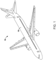
- Figure 1 is a perspective view of an aircraft 10.
- the aircraft 10 is shown as a commercial airliner, but the aircraft 10 could take other forms as well.
- the aircraft 10 includes a fuselage 15.
- FIG. 2 is a cross sectional view of the aircraft 10, more specifically, the fuselage 15.
- the aircraft 10 includes the fuselage 15 and a cargo container area 16 extending through the fuselage 15.
- the cargo container area 16 is defined by a cargo support surface 14 ( e . g ., a floor surface), a cargo area ceiling 13, and opposing sidewalls 18 extending from the cargo support surface 14 and extending from the cargo area ceiling 13.
- the cargo container area 16 has an upper length 17 of approximately 120 inches ( e . g ., 110-130 inches) along the cargo area ceiling 13 and a height 19 of approximately 42.5 inches ( e . g ., 35-45 inches).
- the cargo support surface 14 has an inboard/outboard length of approximately 52 inches ( e . g ., 45-60 inches).
- Figure 3 is a cross sectional view of the aircraft 10, more specifically, the fuselage 15.
- Figure 3 shows a cargo container 100 within the cargo container area 16.
- the cargo container 100 includes opposing sidewalls (e.g., a sidewall 106 and a sidewall 118) that extend in a direction that corresponds to the opposing sidewalls 18 of the cargo container area 16. That is, the sidewall 106 and the sidewall 118 both have an upward slope in the outboard direction like the opposing sidewalls 18 when the cargo container 100 is positioned as shown in Figure 3 .
- the sidewall 106 and the sidewall 118 have slopes or curves that are substantially equal to the slope or curve of the opposing sidewalls 18.
- the sidewall 106 and the sidewall 118 each form a convex surface and the opposing sidewalls 18 each form a concave surface.
- the cargo container 100 is sized (e.g., has a suitable height) to form a gap 11 between the cargo area ceiling 13 and a lid (e.g., top surface) of the cargo container 100.
- This reserves some space within the cargo container area 16 for storing items that are too large for placement within the cargo container 100, further enhancing efficiency.
- Figure 4 is a perspective view of the cargo container 100.
- the cargo container 100 includes a first sidewall 102 having a first length 104 of approximately 96 inches ( e . g ., 85-105 inches) and a second sidewall 106 having a second length 108 of approximately 24 inches (e.g., 20-30 inches) extending transversely from the first sidewall 102.
- the first length 104 is greater than the second length 108.
- the cargo container 100 further includes a base sidewall 110 extending from the first sidewall 102 and the second sidewall 106.
- the base sidewall 110 is configured to support the cargo container 100 on the cargo support surface 14 of the aircraft 10.
- the cargo container 100 further includes a lid 112 configured to couple (e.g., via a hinge) to the first sidewall 102, the second sidewall 106, or the base sidewall 110 to at least partially cover a cavity 114 formed by the first sidewall 102, the second sidewall 106, and the base sidewall 110.
- the lid 112 is attached to the first sidewall 102.
- the cargo container 100 has a height 107 of approximately 28 inches ( e . g ., 25-35 inches).
- the cargo container 100 also includes a third sidewall 118 extending from the first sidewall 102 and opposite the second sidewall 106.
- the second sidewall 106 and the third sidewall 118 together exhibit reflectional symmetry, which can facilitate a good fit with the opposing sidewalls 18 and efficient use of the cargo container area 16.
- the third sidewall 118 can include any or all features of the second sidewall 106.
- the second sidewall 106 comprises a panel portion 116 that extends ( e . g ., curves) in a direction that corresponds to the sidewalls 18 of the cargo container area 16 of the aircraft 10.
- the panel portion 116 is curved in a way that resembles the curve of the sidewalls 18 of the cargo container area 16.
- the second sidewall 106 transitions from being perpendicular to the base sidewall 110 at the top of the second sidewall 106 to being parallel with the base sidewall 110 at the bottom of the second sidewall 106.
- the shape of the panel portion 116 e . g ., the second sidewall 106 and/or the third sidewall 118
- the first sidewall 102, the second sidewall 106, the third sidewall 118, and the base sidewall 110 are formed of a unitary body (e.g., via a rotational molding process).
- the first sidewall 102, the second sidewall 106, the third sidewall 118, and the base sidewall 110 are generally formed of plastic and/or a low friction material such as polytetrafluoroethylene (PTFE) and/or ultra-high-molecular-weight polyethylene (UHMW), but other materials are possible.
- PTFE polytetrafluoroethylene
- UHMW ultra-high-molecular-weight polyethylene
- the first sidewall 102, the second sidewall 106, the third sidewall 118, and the base sidewall 110 being formed of a unitary plastic body can result in the cargo container 100 being lightweight yet strong.
- the base sidewall 110 is equal in length, parallel to the first sidewall 102, to the length of the cargo support surface 14 of the aircraft 10 in the inboard/outboard direction.
- the first sidewall 102, the second sidewall 106, the third sidewall 118, and/or the base sidewall 110 include stiffening ribs formed via rotational molding process.
- the cargo container 100 also includes a plurality of wheels 120 that extend from the base sidewall 110 and are configured for supporting and rolling the cargo container 100, for example, on the cargo support surface 14 or on a ramp that connects a tarmac to the cargo support surface 14.
- the cargo container 100 also includes a base plate 121 fastened to the base sidewall 110.
- the cargo container 100 can be slid along the base plate 121.
- the base plate 121 could be formed of a low-friction or friction reducing material such as polytetrafluoroethylene (PTFE).
- the cargo container 100 includes a first lip portion 144 that is substantially parallel to the first sidewall 102 and that extends from the base sidewall 110.
- the cargo container 100 also includes a second lip portion 146 that is substantially parallel to the first sidewall 102 and extends from the second sidewall 106.
- the first lip portion 144 and the second lip portion 146 can help prevent cargo items from falling horizontally out of the cavity 114 during loading of the cargo container 100.
- the first length 104 being greater than the second length 108 (e.g., at least four times greater) helps the cargo container 100 facilitate more efficient and more ergonomic loading of cargo into the aircraft 10, as shown in Figure 5 .
- Figure 5 is a cut away view of the fuselage 15.
- the fuselage 15 e.g., the cargo container area 16
- the cargo containers 100 contain many items of luggage as shown.
- the first length 104 is chosen such that the second sidewalls 106 and the third sidewalls 118 of the cargo containers 100 conform to the sidewalls 18 to some degree.
- the second length 108 can be slightly greater than a standardized height of a typical item of luggage so that luggage can be efficiently stacked within the cargo containers 100.
- the second length 108 will also generally be small enough so that the cargo container 100 is easily loaded through a cargo door of the aircraft 10.
- the cargo containers 100 being sized in the inboard-outboard direction to somewhat conform to the sidewalls 18 can increase the amount of cargo that can be carried within the cargo container area 16.
- Figure 6 is a perspective view of the cargo container 100.
- the cargo container 100 includes a second sidewall 106 and a third sidewall 118 that are not curved, in contrast to the cargo container 100 shown in Figure 4 .
- any features of the cargo container 100 shown in Figure 4 can be combined with the features of the cargo container 100 shown in Figure 6 , and vice versa.
- the cargo container 100 includes a first rub strip 122 comprising a low friction or friction reducing material (e.g., PTFE) on a first side 124 of the base plate 121 and a second rub strip 122 comprising the low friction or friction reducing material on a second side 128 of the base plate 121 that is opposite the first side 124.
- the first rub strip 122 and the second rub strip 122 can facilitate sliding the cargo container 100 over the cargo support surface 14.
- Additional rub strips 122 comprising the low friction or friction reducing material on opposite sides near the lid 112 can help move the cargo container 100 against the sidewalls 18 of the cargo container area 16.
- first sidewall 102 (not shown), the second sidewall 106 (not shown), the third sidewall 118, a fourth sidewall 103, and/or the base sidewall 110 are honeycomb composite panels joined together mechanically with fasteners and/or tab and slot connections.
- FIG 7 is a perspective view of the cargo container 100.
- the cargo container 100 further includes a flexible cover 148 (e.g., made of canvas) configured to be fastened (e.g., via snap fittings) to the first lip portion 144 and the second lip portion 146 to at least partially cover the cavity 114.
- the flexible cover 148 being removable and lightweight can help make loading the cargo container 100 easier by providing a large opening through which to place cargo in the cavity 114 and by providing a quick means for closing the cargo container 100 after loading.
- the flexible cover 148 and the lid 112 together are configured to completely cover the cavity 114.
- the flexible cover 148 is replaced by a fourth sidewall 103 opposite the first sidewall 102.
- the fourth sidewall 103 can have any of the characteristics of the first sidewall 102.
- the cargo container 100 also includes a first flexible handle 130 on a first end 132 of the cargo container 100 and a second flexible handle 130 on a second end 136 of the cargo container 100 that is opposite the first end 132. This is shown in more detail in Figure 8 .
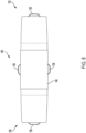
- Figure 8 is a bottom view of the cargo container 100.
- the cargo container 100 includes the first flexible handle 130 on the first end 132 of the cargo container 100 and the second flexible handle 130 on the second end 136 of the cargo container 100 that is opposite the first end 132.
- the cargo container also includes additional flexible handles 130 as shown.
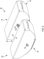
- Figure 9 is a perspective view of two cargo containers 100.
- Both cargo containers 100 include a first linkage device 138 of a first type (e.g., a hook) that is coupled to a first side 143 of the cargo container 100 and a second linkage device 140 of a second type (e.g., an eye bolt) that is coupled to a second side 142 of the cargo container 100 that is opposite the first side 143.
- the first linkage device 138 is configured to be coupled to the second linkage device 140. More generally, any first linkage device 138 on a first side 143 of any cargo container 100 is configured to couple to any second linkage device 140 of the second type that is on a second side 142 of any other cargo container 100.
- a first linkage device 138 of a first cargo container can be coupled to a second linkage device 140 of a second cargo container and a second linkage device 140 of the first cargo container can be coupled to a first linkage device 138 of a third cargo container.
- the linkage devices can aid with the process of loading and unloading the cargo containers 100 into the cargo container area 16.
- the space between the cargo containers 100 facilitated by the linkage devices is exaggerated as well as the size of the linkage devices themselves.
- the linkage devices are smaller than shown but serve the purpose of attaching the cargo containers 100 to each other with a small distance separating the cargo containers 100, so as to efficiently pack as much cargo into the cargo container area 16 as possible.
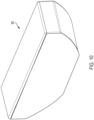
- Figure 10 is a perspective view of a closed container 101.
- the closed container 101 is formed via a rotational molding process. For example, a mold that is spinning ( e . g ., about two perpendicular axes) is filled with molten plastic. The centrifugal forces force the molten plastic against the inner surfaces of the mold and the molten plastic is allowed to cool while spinning to form the closed container 101.
- the closed container 101 is typically a unitary body of plastic, but other examples are possible.
- Figure 11 is a perspective view of an open container 113 and the lid 112.
- the lid 112 is produced by removing (e.g., cutting) the lid 112 from the closed container 101 to form the lid 112 and the open container 113.
- the lid 112 can be attached to the open container 113 such that the lid 112 can rotate with respect to the open container 113, thereby forming the cargo container 100.
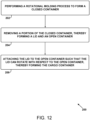
- Figure 12 is a block diagram of a method 200 of manufacturing the cargo container 100.
- the method 200 includes one or more operations, functions, or actions as illustrated by blocks 202, 204, and 206. Although the blocks are illustrated in a sequential order, these blocks may also be performed in parallel, and/or in a different order than those described herein. Also, the various blocks may be combined into fewer blocks, divided into additional blocks, and/or removed based upon the desired implementation.
- the method 200 includes performing a rotational molding process to form the closed container 101.
- the method 200 includes removing a portion of the closed container 101, thereby forming the lid 112 and the open container 113.
- the method 200 includes attaching the lid 112 to the open container 113 such that the lid 112 can rotate with respect to the open container 113, thereby forming the cargo container 100.
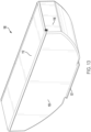
- Figure 13 is a perspective view of the cargo container 100.
- the cargo container 100 includes the base plate 121.
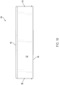
- Figure 14 is a front view of the cargo container 100.
- Figure 15 is a rear view of the cargo container 100.
- Figure 16 is a right side view of the cargo container 100.
- Figure 17 is a left side view of the cargo container 100.
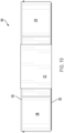
- Figure 18 is a top view of the cargo container 100.
- Figure 19 is a bottom view of the cargo container 100.
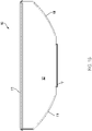
- Figure 20 is a cross sectional view of the cargo container 100.
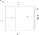
- Figure 21 is a cross sectional view of the cargo container 100.
- Figure 22 is a perspective view of the cargo container 100. In Figures 22-30 , the cargo container 100 does not include the base plate 121.
- Figure 23 is a front view of the cargo container 100.
- Figure 24 is a rear view of the cargo container 100.
- Figure 25 is a right side view of the cargo container 100.
- Figure 26 is a left side view of the cargo container 100.
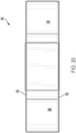
- Figure 27 is a top view of the cargo container 100.
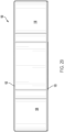
- Figure 28 is a bottom view of the cargo container 100.
- Figure 29 is a cross sectional view of the cargo container 100.
- Figure 30 is a cross sectional view of the cargo container 100.
- Examples of the present disclosure can thus relate to one of the enumerated clauses (ECs) listed below.
- EC 1 is a cargo container for carrying items in an aircraft, the cargo container comprising: a first sidewall comprising a first length; a second sidewall comprising a second length extending transversely from the first sidewall, wherein the first length is greater than the second length; a base sidewall extending from the first sidewall and the second sidewall, wherein the base sidewall is configured to support the cargo container on a cargo support surface of the aircraft; and a lid configured to couple to the first sidewall, the second sidewall, or the base sidewall to at least partially cover a cavity formed by the first sidewall, the second sidewall, and the base sidewall.
- EC 2 is the cargo container of EC 1, wherein the first length is at least four times that of the second length.
- EC 3 is the cargo container of any of ECs 1-2, wherein the second sidewall comprises a panel portion that extends in a direction that corresponds to a sidewall of a cargo container area of the aircraft.
- EC 4 is the cargo container of EC 3, wherein the panel portion is curved.
- EC 5 is the cargo container of any of ECs 1-4, wherein the second sidewall transitions from being perpendicular to the base sidewall to being parallel with the base sidewall.
- EC 6 is the cargo container of any of ECs 1-5, further comprising a third sidewall extending from the first sidewall and opposite the second sidewall, wherein the second sidewall and the third sidewall together exhibit reflectional symmetry.
- EC 7 is the cargo container of any of ECs 1-6, wherein the first sidewall, the second sidewall, and the base sidewall are formed of a unitary body.
- EC 8 is the cargo container of any of ECs 1-7, wherein the base sidewall comprises a low-friction material.
- EC 9 is the cargo container of any of ECs 1-8, further comprising a base plate fastened to the base sidewall.
- EC 10 is the cargo container of EC 9, further comprising: a first rub strip comprising a low friction material on a first side of the base plate; and a second rub strip comprising the low friction material on a second side of the base plate, wherein the second side is opposite the first side.
- EC 11 is the cargo container of any of ECs 1-10, further comprising: a first flexible handle on a first end of the cargo container; and a second flexible handle on a second end of the cargo container that is opposite the first end.
- EC 12 is the cargo container of any of ECs 1-11, further comprising: a first linkage device of a first type that is coupled to a first side of the cargo container; and a second linkage device of a second type that is coupled to a second side of the cargo container that is opposite the first side, wherein the first linkage device is configured to be coupled to a linkage device of the second type that is coupled to a second cargo container, and wherein the second linkage device is configured to be coupled to a linkage device of the first type that is coupled to a third cargo container.
- EC 13 is the cargo container of any of ECs 1-12, further comprising a first lip portion that is substantially parallel to the first sidewall and extends from the base sidewall.
- EC 14 is the cargo container of EC 13, further comprising a second lip portion that is substantially parallel to the first sidewall and extends from the second sidewall.
- EC 15 is the cargo container of EC 14, further comprising a flexible cover configured to be fastened to the first lip portion and the second lip portion to at least partially cover the cavity.
- EC 16 is the cargo container of EC 15, wherein the flexible cover and the lid together are configured to completely cover the cavity.
- EC 17 is cargo container of any of ECs 1-16, further comprising: a third sidewall extending from the first sidewall and opposite the second sidewall, wherein the second sidewall and the third sidewall together exhibit reflectional symmetry; a base plate fastened to the base sidewall; a first rub strip comprising a low friction material on a first side of the base plate; a second rub strip comprising the low friction material on a second side of the base plate, wherein the second side is opposite the first side; a first flexible handle on a first end of the cargo container; a second flexible handle on a second end of the cargo container that is opposite the first end; a first linkage device of a first type that is coupled to a first side of the cargo container; and a second linkage device of a second type that is coupled to a second side of the cargo container that is opposite the first end, wherein the first linkage device is configured to be coupled to a linkage device of the second type that is coupled to a second cargo container, and wherein the second linkage device is
- EC 18 is an aircraft comprising: a fuselage; a cargo container area extending through the fuselage, the cargo container area defined by a cargo support surface and opposing sidewalls extending from the cargo support surface; and a plurality of cargo containers within the cargo container area, wherein each cargo container of the plurality of cargo containers comprises opposing sidewalls that extend in a direction that correspond to the opposing sidewalls of the cargo container area.
- EC 19 is the aircraft of EC 18, wherein each cargo container of the plurality of cargo containers is formed of a unitary body.
- EC 20 is a method of manufacturing a cargo container, the method comprising: performing a rotational molding process to form a closed container; removing a portion of the closed container, thereby forming a lid and an open container; and attaching the lid to the open container such that the lid can rotate with respect to the open container, thereby forming the cargo container.
Landscapes
- Engineering & Computer Science (AREA)
- Mechanical Engineering (AREA)
- Aviation & Aerospace Engineering (AREA)
- Packaging Of Machine Parts And Wound Products (AREA)
Abstract
Description
- The present disclosure generally relates to cargo containers, and more specifically to cargo containers for carrying items in an aircraft.
- Aircraft are commonly used to transport cargo in addition to passengers. One common practice for loading cargo such as luggage into an aircraft involves a first handler on the tarmac and a second handler in a cargo area of the aircraft. The first handler places luggage items (e.g., one by one) on the floor of the cargo area near a cargo door and the second handler retrieves the luggage items and stacks them in the cargo area. Other handlers might be involved as well. In some cases, a conveyor system moves the stacked cargo to the rear of the plane so that the second handler can stack additional luggage items. This process can be tedious and unpleasant as the second handler often must crouch or bend over due to the low ceiling of the cargo area. In addition, the process can result in inefficient use of the volume of the cargo area and individual handling of luggage items can increase the risk of mishandling that causes damage.
- One aspect of the disclosure is a cargo container for carrying items in an aircraft, the cargo container comprising: a first sidewall comprising a first length; a second sidewall comprising a second length extending transversely from the first sidewall, wherein the first length is greater than the second length; a base sidewall extending from the first sidewall and the second sidewall, wherein the base sidewall is configured to support the cargo container on a cargo support surface of the aircraft; and a lid configured to couple to the first sidewall, the second sidewall, or the base sidewall to at least partially cover a cavity formed by the first sidewall, the second sidewall, and the base sidewall.
- Another aspect of the disclosure is an aircraft comprising: a fuselage; a cargo container area extending through the fuselage, the cargo container area defined by a cargo support surface and opposing sidewalls extending from the cargo support surface; and a plurality of cargo containers within the cargo container area, wherein each cargo container of the plurality of cargo containers comprises opposing sidewalls that extend in a direction that correspond to the opposing sidewalls of the cargo container area.
- Another aspect of the disclosure is a method of manufacturing a cargo container, the method comprising: performing a rotational molding process to form a closed container; removing a portion of the closed container, thereby forming a lid and an open container; and attaching the lid to the open container such that the lid can rotate with respect to the open container, thereby forming the cargo container.
- By the term "about" or "substantially" with reference to amounts or measurement values described herein, it is meant that the recited characteristic, parameter, or value need not be achieved exactly, but that deviations or variations, including for example, tolerances, measurement error, measurement accuracy limitations and other factors known to those of skill in the art, may occur in amounts that do not preclude the effect the characteristic was intended to provide.
- The features, functions, and advantages that have been discussed can be achieved independently in various examples or may be combined in yet other examples further details of which can be seen with reference to the following description and drawings.
- The novel features believed characteristic of the illustrative examples are set forth in the appended claims. The illustrative examples, however, as well as a preferred mode of use, further objectives and descriptions thereof, will best be understood by reference to the following detailed description of an illustrative example of the present disclosure when read in conjunction with the accompanying Figures.
-
Figure 1 is a perspective view of an aircraft, according to an example. -
Figure 2 is a cross sectional view of an aircraft, according to an example. -
Figure 3 is a cross sectional view of an aircraft and a cargo container, according to an example. -
Figure 4 is a perspective view of a cargo container, according to an example. -
Figure 5 is a cut away view of a fuselage and cargo containers, according to an example. -
Figure 6 is a perspective view of a cargo container, according to an example. -
Figure 7 is a perspective view of a cargo container, according to an example. -
Figure 8 is a bottom view of a cargo container, according to an example. -
Figure 9 is a perspective view of cargo containers, according to an example. -
Figure 10 is a perspective view of a closed container, according to an example. -
Figure 11 is a perspective view of an open container and a lid, according to an example. -
Figure 12 is a block diagram of a method, according to an example. -
Figure 13 is a perspective view of a cargo container, according to an example. -
Figure 14 is a front view of a cargo container, according to an example. -
Figure 15 is a rear view of a cargo container, according to an example. -
Figure 16 is a right side view of a cargo container, according to an example. -
Figure 17 is a left side view of a cargo container, according to an example. -
Figure 18 is a top view of a cargo container, according to an example. -
Figure 19 is a bottom view of a cargo container, according to an example. -
Figure 20 is a cross sectional view of a cargo container, according to an example. -
Figure 21 is a cross sectional view of a cargo container, according to an example. -
Figure 22 is a perspective view of a cargo container, according to an example. -
Figure 23 is a front view of a cargo container, according to an example. -
Figure 24 is a rear view of a cargo container, according to an example. -
Figure 25 is a right side view of a cargo container, according to an example. -
Figure 26 is a left side view of a cargo container, according to an example. -
Figure 27 is a top view of a cargo container, according to an example. -
Figure 28 is a bottom view of a cargo container, according to an example. -
Figure 29 is a cross sectional view of a cargo container, according to an example. -
Figure 30 is a cross sectional view of a cargo container, according to an example. - A need exists for a cargo container that facilitates more efficient and more ergonomic loading of cargo into an aircraft. Examples herein include a cargo container for carrying items in an aircraft. The cargo container includes a first sidewall including a first length and a second sidewall including a second length extending transversely from the first sidewall. The first length is greater than the second length. The cargo container further includes a base sidewall extending from the first sidewall and the second sidewall, where the base sidewall is configured to support the cargo container on a cargo support surface of the aircraft. The cargo container further includes a lid configured to couple to the first sidewall, the second sidewall, or the base sidewall to at least partially cover a cavity formed by the first sidewall, the second sidewall, and the base sidewall. As described below, the cargo container has several features that can facilitate more efficient and ergonomic loading of cargo into an aircraft.
- Typical cargo containers used for loading luggage into an aircraft are heavy, large, and expensively constructed when compared to the cargo containers disclosed herein. Because of their heavy weight and/or large size, such conventional cargo containers are subject to various structural requirements of certain regulatory agencies. The cargo containers disclosed herein generally include lightweight materials and are smaller than typical cargo containers (e.g., in a dimension parallel to the longitudinal axis of the aircraft), thus obviating the need to satisfy such regulatory requirements.
- Disclosed examples will now be described more fully hereinafter with reference to the accompanying Drawings, in which some, but not all of the disclosed examples are shown. Indeed, several different examples may be described and should not be construed as limited to the examples set forth herein. Rather, these examples are described so that this disclosure will be thorough and complete and will fully convey the scope of the disclosure to those skilled in the art.
-
Figures 1-11 are diagrams of structures and functionality related to acargo container 100. -
Figure 1 is a perspective view of anaircraft 10. Theaircraft 10 is shown as a commercial airliner, but theaircraft 10 could take other forms as well. Theaircraft 10 includes afuselage 15. -
Figure 2 is a cross sectional view of theaircraft 10, more specifically, thefuselage 15. Theaircraft 10 includes thefuselage 15 and acargo container area 16 extending through thefuselage 15. Thecargo container area 16 is defined by a cargo support surface 14 (e.g., a floor surface), acargo area ceiling 13, and opposingsidewalls 18 extending from thecargo support surface 14 and extending from thecargo area ceiling 13. - The
cargo container area 16 has an upper length 17 of approximately 120 inches (e.g., 110-130 inches) along thecargo area ceiling 13 and aheight 19 of approximately 42.5 inches (e.g., 35-45 inches). Thecargo support surface 14 has an inboard/outboard length of approximately 52 inches (e.g., 45-60 inches). -
Figure 3 is a cross sectional view of theaircraft 10, more specifically, thefuselage 15.Figure 3 shows acargo container 100 within thecargo container area 16. Thecargo container 100 includes opposing sidewalls (e.g., asidewall 106 and a sidewall 118) that extend in a direction that corresponds to the opposingsidewalls 18 of thecargo container area 16. That is, thesidewall 106 and thesidewall 118 both have an upward slope in the outboard direction like the opposingsidewalls 18 when thecargo container 100 is positioned as shown inFigure 3 . In other examples, thesidewall 106 and thesidewall 118 have slopes or curves that are substantially equal to the slope or curve of the opposingsidewalls 18. As shown inFigure 3 , thesidewall 106 and thesidewall 118 each form a convex surface and the opposingsidewalls 18 each form a concave surface. - As shown in
Figure 3 , thecargo container 100 is sized (e.g., has a suitable height) to form agap 11 between thecargo area ceiling 13 and a lid (e.g., top surface) of thecargo container 100. This reserves some space within thecargo container area 16 for storing items that are too large for placement within thecargo container 100, further enhancing efficiency. -
Figure 4 is a perspective view of thecargo container 100. Thecargo container 100 includes afirst sidewall 102 having afirst length 104 of approximately 96 inches (e.g., 85-105 inches) and asecond sidewall 106 having asecond length 108 of approximately 24 inches (e.g., 20-30 inches) extending transversely from thefirst sidewall 102. Thefirst length 104 is greater than thesecond length 108. Thecargo container 100 further includes abase sidewall 110 extending from thefirst sidewall 102 and thesecond sidewall 106. Thebase sidewall 110 is configured to support thecargo container 100 on thecargo support surface 14 of theaircraft 10. Thecargo container 100 further includes alid 112 configured to couple (e.g., via a hinge) to thefirst sidewall 102, thesecond sidewall 106, or thebase sidewall 110 to at least partially cover acavity 114 formed by thefirst sidewall 102, thesecond sidewall 106, and thebase sidewall 110. In the example ofFigure 4 , thelid 112 is attached to thefirst sidewall 102. Thecargo container 100 has aheight 107 of approximately 28 inches (e.g., 25-35 inches). - The
cargo container 100 also includes athird sidewall 118 extending from thefirst sidewall 102 and opposite thesecond sidewall 106. Thesecond sidewall 106 and thethird sidewall 118 together exhibit reflectional symmetry, which can facilitate a good fit with the opposingsidewalls 18 and efficient use of thecargo container area 16. Thethird sidewall 118 can include any or all features of thesecond sidewall 106. - The
second sidewall 106 comprises apanel portion 116 that extends (e.g., curves) in a direction that corresponds to thesidewalls 18 of thecargo container area 16 of theaircraft 10. For example, thepanel portion 116 is curved in a way that resembles the curve of thesidewalls 18 of thecargo container area 16. In this way, thesecond sidewall 106 transitions from being perpendicular to thebase sidewall 110 at the top of thesecond sidewall 106 to being parallel with thebase sidewall 110 at the bottom of thesecond sidewall 106. In this way, the shape of the panel portion 116 (e.g., thesecond sidewall 106 and/or the third sidewall 118) can facilitate efficient cargo loading within thecargo container area 16. - The
first sidewall 102, thesecond sidewall 106, thethird sidewall 118, and thebase sidewall 110 are formed of a unitary body (e.g., via a rotational molding process). Thefirst sidewall 102, thesecond sidewall 106, thethird sidewall 118, and thebase sidewall 110 are generally formed of plastic and/or a low friction material such as polytetrafluoroethylene (PTFE) and/or ultra-high-molecular-weight polyethylene (UHMW), but other materials are possible. Thebase sidewall 110 including PTFE can help provide a surface upon which thecargo container 100 can be slid easily. Thefirst sidewall 102, thesecond sidewall 106, thethird sidewall 118, and thebase sidewall 110 being formed of a unitary plastic body can result in thecargo container 100 being lightweight yet strong. In some examples, thebase sidewall 110 is equal in length, parallel to thefirst sidewall 102, to the length of thecargo support surface 14 of theaircraft 10 in the inboard/outboard direction. In some examples, thefirst sidewall 102, thesecond sidewall 106, thethird sidewall 118, and/or thebase sidewall 110 include stiffening ribs formed via rotational molding process. - The
cargo container 100 also includes a plurality ofwheels 120 that extend from thebase sidewall 110 and are configured for supporting and rolling thecargo container 100, for example, on thecargo support surface 14 or on a ramp that connects a tarmac to thecargo support surface 14. - The
cargo container 100 also includes abase plate 121 fastened to thebase sidewall 110. In examples in which thewheels 120 are not included, thecargo container 100 can be slid along thebase plate 121. For example, thebase plate 121 could be formed of a low-friction or friction reducing material such as polytetrafluoroethylene (PTFE). - The
cargo container 100 includes afirst lip portion 144 that is substantially parallel to thefirst sidewall 102 and that extends from thebase sidewall 110. Thecargo container 100 also includes asecond lip portion 146 that is substantially parallel to thefirst sidewall 102 and extends from thesecond sidewall 106. Thefirst lip portion 144 and thesecond lip portion 146 can help prevent cargo items from falling horizontally out of thecavity 114 during loading of thecargo container 100. - The
first length 104 being greater than the second length 108 (e.g., at least four times greater) helps thecargo container 100 facilitate more efficient and more ergonomic loading of cargo into theaircraft 10, as shown inFigure 5 . -
Figure 5 is a cut away view of thefuselage 15. As shown, the fuselage 15 (e.g., the cargo container area 16) contains several of thecargo containers 100. Thecargo containers 100 contain many items of luggage as shown. In an example, thefirst length 104 is chosen such that thesecond sidewalls 106 and thethird sidewalls 118 of thecargo containers 100 conform to thesidewalls 18 to some degree. Thesecond length 108 can be slightly greater than a standardized height of a typical item of luggage so that luggage can be efficiently stacked within thecargo containers 100. Thesecond length 108 will also generally be small enough so that thecargo container 100 is easily loaded through a cargo door of theaircraft 10. Thecargo containers 100 being sized in the inboard-outboard direction to somewhat conform to thesidewalls 18 can increase the amount of cargo that can be carried within thecargo container area 16. -
Figure 6 is a perspective view of thecargo container 100. InFigure 6 , thecargo container 100 includes asecond sidewall 106 and athird sidewall 118 that are not curved, in contrast to thecargo container 100 shown inFigure 4 . However, any features of thecargo container 100 shown inFigure 4 can be combined with the features of thecargo container 100 shown inFigure 6 , and vice versa. - In
Figure 6 , thecargo container 100 includes afirst rub strip 122 comprising a low friction or friction reducing material (e.g., PTFE) on afirst side 124 of thebase plate 121 and asecond rub strip 122 comprising the low friction or friction reducing material on asecond side 128 of thebase plate 121 that is opposite thefirst side 124. Thefirst rub strip 122 and thesecond rub strip 122 can facilitate sliding thecargo container 100 over thecargo support surface 14. Additional rub strips 122 comprising the low friction or friction reducing material on opposite sides near thelid 112 can help move thecargo container 100 against thesidewalls 18 of thecargo container area 16. - In
Figure 6 , the first sidewall 102 (not shown), the second sidewall 106 (not shown), thethird sidewall 118, afourth sidewall 103, and/or thebase sidewall 110 are honeycomb composite panels joined together mechanically with fasteners and/or tab and slot connections. -
Figure 7 is a perspective view of thecargo container 100. Thecargo container 100 further includes a flexible cover 148 (e.g., made of canvas) configured to be fastened (e.g., via snap fittings) to thefirst lip portion 144 and thesecond lip portion 146 to at least partially cover thecavity 114. Theflexible cover 148 being removable and lightweight can help make loading thecargo container 100 easier by providing a large opening through which to place cargo in thecavity 114 and by providing a quick means for closing thecargo container 100 after loading. Theflexible cover 148 and thelid 112 together are configured to completely cover thecavity 114. In some examples, such as the examples shown inFigures 13-30 , theflexible cover 148 is replaced by afourth sidewall 103 opposite thefirst sidewall 102. Thefourth sidewall 103 can have any of the characteristics of thefirst sidewall 102. - The
cargo container 100 also includes a firstflexible handle 130 on afirst end 132 of thecargo container 100 and a secondflexible handle 130 on asecond end 136 of thecargo container 100 that is opposite thefirst end 132. This is shown in more detail inFigure 8 . -
Figure 8 is a bottom view of thecargo container 100. Thecargo container 100 includes the firstflexible handle 130 on thefirst end 132 of thecargo container 100 and the secondflexible handle 130 on thesecond end 136 of thecargo container 100 that is opposite thefirst end 132. The cargo container also includes additionalflexible handles 130 as shown. -
Figure 9 is a perspective view of twocargo containers 100. Bothcargo containers 100 include a first linkage device 138 of a first type (e.g., a hook) that is coupled to a first side 143 of thecargo container 100 and a second linkage device 140 of a second type (e.g., an eye bolt) that is coupled to a second side 142 of thecargo container 100 that is opposite the first side 143. As shown, the first linkage device 138 is configured to be coupled to the second linkage device 140. More generally, any first linkage device 138 on a first side 143 of anycargo container 100 is configured to couple to any second linkage device 140 of the second type that is on a second side 142 of anyother cargo container 100. As such, a first linkage device 138 of a first cargo container can be coupled to a second linkage device 140 of a second cargo container and a second linkage device 140 of the first cargo container can be coupled to a first linkage device 138 of a third cargo container. The linkage devices can aid with the process of loading and unloading thecargo containers 100 into thecargo container area 16. - For the purpose of ease of illustration, the space between the
cargo containers 100 facilitated by the linkage devices is exaggerated as well as the size of the linkage devices themselves. Generally, the linkage devices are smaller than shown but serve the purpose of attaching thecargo containers 100 to each other with a small distance separating thecargo containers 100, so as to efficiently pack as much cargo into thecargo container area 16 as possible. -
Figure 10 is a perspective view of a closed container 101. The closed container 101 is formed via a rotational molding process. For example, a mold that is spinning (e.g., about two perpendicular axes) is filled with molten plastic. The centrifugal forces force the molten plastic against the inner surfaces of the mold and the molten plastic is allowed to cool while spinning to form the closed container 101. The closed container 101 is typically a unitary body of plastic, but other examples are possible. -
Figure 11 is a perspective view of anopen container 113 and thelid 112. Thelid 112 is produced by removing (e.g., cutting) thelid 112 from the closed container 101 to form thelid 112 and theopen container 113. As shown inFigure 4 , thelid 112 can be attached to theopen container 113 such that thelid 112 can rotate with respect to theopen container 113, thereby forming thecargo container 100. -
Figure 12 is a block diagram of amethod 200 of manufacturing thecargo container 100. As shown inFigure 12 , themethod 200 includes one or more operations, functions, or actions as illustrated byblocks - Details regarding the
blocks Figures 4 ,10 , and11 . - At
block 202, themethod 200 includes performing a rotational molding process to form the closed container 101. - At
block 204, themethod 200 includes removing a portion of the closed container 101, thereby forming thelid 112 and theopen container 113. - At
block 206, themethod 200 includes attaching thelid 112 to theopen container 113 such that thelid 112 can rotate with respect to theopen container 113, thereby forming thecargo container 100. -
Figure 13 is a perspective view of thecargo container 100. InFigures 13-21 , thecargo container 100 includes thebase plate 121. -
Figure 14 is a front view of thecargo container 100. -
Figure 15 is a rear view of thecargo container 100. -
Figure 16 is a right side view of thecargo container 100. -
Figure 17 is a left side view of thecargo container 100. -
Figure 18 is a top view of thecargo container 100. -
Figure 19 is a bottom view of thecargo container 100. -
Figure 20 is a cross sectional view of thecargo container 100. -
Figure 21 is a cross sectional view of thecargo container 100. -
Figure 22 is a perspective view of thecargo container 100. InFigures 22-30 , thecargo container 100 does not include thebase plate 121. -
Figure 23 is a front view of thecargo container 100. -
Figure 24 is a rear view of thecargo container 100. -
Figure 25 is a right side view of thecargo container 100. -
Figure 26 is a left side view of thecargo container 100. -
Figure 27 is a top view of thecargo container 100. -
Figure 28 is a bottom view of thecargo container 100. -
Figure 29 is a cross sectional view of thecargo container 100. -
Figure 30 is a cross sectional view of thecargo container 100. - Examples of the present disclosure can thus relate to one of the enumerated clauses (ECs) listed below.
- EC 1 is a cargo container for carrying items in an aircraft, the cargo container comprising: a first sidewall comprising a first length; a second sidewall comprising a second length extending transversely from the first sidewall, wherein the first length is greater than the second length; a base sidewall extending from the first sidewall and the second sidewall, wherein the base sidewall is configured to support the cargo container on a cargo support surface of the aircraft; and a lid configured to couple to the first sidewall, the second sidewall, or the base sidewall to at least partially cover a cavity formed by the first sidewall, the second sidewall, and the base sidewall.
- EC 2 is the cargo container of EC 1, wherein the first length is at least four times that of the second length.
- EC 3 is the cargo container of any of ECs 1-2, wherein the second sidewall comprises a panel portion that extends in a direction that corresponds to a sidewall of a cargo container area of the aircraft.
- EC 4 is the cargo container of EC 3, wherein the panel portion is curved.
- EC 5 is the cargo container of any of ECs 1-4, wherein the second sidewall transitions from being perpendicular to the base sidewall to being parallel with the base sidewall.
- EC 6 is the cargo container of any of ECs 1-5, further comprising a third sidewall extending from the first sidewall and opposite the second sidewall, wherein the second sidewall and the third sidewall together exhibit reflectional symmetry.
- EC 7 is the cargo container of any of ECs 1-6, wherein the first sidewall, the second sidewall, and the base sidewall are formed of a unitary body.
- EC 8 is the cargo container of any of ECs 1-7, wherein the base sidewall comprises a low-friction material.
- EC 9 is the cargo container of any of ECs 1-8, further comprising a base plate fastened to the base sidewall.
-
EC 10 is the cargo container of EC 9, further comprising: a first rub strip comprising a low friction material on a first side of the base plate; and a second rub strip comprising the low friction material on a second side of the base plate, wherein the second side is opposite the first side. -
EC 11 is the cargo container of any of ECs 1-10, further comprising: a first flexible handle on a first end of the cargo container; and a second flexible handle on a second end of the cargo container that is opposite the first end. - EC 12 is the cargo container of any of ECs 1-11, further comprising: a first linkage device of a first type that is coupled to a first side of the cargo container; and a second linkage device of a second type that is coupled to a second side of the cargo container that is opposite the first side, wherein the first linkage device is configured to be coupled to a linkage device of the second type that is coupled to a second cargo container, and wherein the second linkage device is configured to be coupled to a linkage device of the first type that is coupled to a third cargo container.
-
EC 13 is the cargo container of any of ECs 1-12, further comprising a first lip portion that is substantially parallel to the first sidewall and extends from the base sidewall. -
EC 14 is the cargo container ofEC 13, further comprising a second lip portion that is substantially parallel to the first sidewall and extends from the second sidewall. -
EC 15 is the cargo container ofEC 14, further comprising a flexible cover configured to be fastened to the first lip portion and the second lip portion to at least partially cover the cavity. -
EC 16 is the cargo container ofEC 15, wherein the flexible cover and the lid together are configured to completely cover the cavity. - EC 17 is cargo container of any of ECs 1-16, further comprising: a third sidewall extending from the first sidewall and opposite the second sidewall, wherein the second sidewall and the third sidewall together exhibit reflectional symmetry; a base plate fastened to the base sidewall; a first rub strip comprising a low friction material on a first side of the base plate; a second rub strip comprising the low friction material on a second side of the base plate, wherein the second side is opposite the first side; a first flexible handle on a first end of the cargo container; a second flexible handle on a second end of the cargo container that is opposite the first end; a first linkage device of a first type that is coupled to a first side of the cargo container; and a second linkage device of a second type that is coupled to a second side of the cargo container that is opposite the first end, wherein the first linkage device is configured to be coupled to a linkage device of the second type that is coupled to a second cargo container, and wherein the second linkage device is configured to be coupled to a linkage device of the first type that is coupled to a third cargo container, wherein the first length is at least four times that of the second length, and wherein the second sidewall comprises a panel portion that extends in a direction that corresponds to a sidewall cargo surface of the aircraft.
-
EC 18 is an aircraft comprising: a fuselage; a cargo container area extending through the fuselage, the cargo container area defined by a cargo support surface and opposing sidewalls extending from the cargo support surface; and a plurality of cargo containers within the cargo container area, wherein each cargo container of the plurality of cargo containers comprises opposing sidewalls that extend in a direction that correspond to the opposing sidewalls of the cargo container area. -
EC 19 is the aircraft ofEC 18, wherein each cargo container of the plurality of cargo containers is formed of a unitary body. -
EC 20 is a method of manufacturing a cargo container, the method comprising: performing a rotational molding process to form a closed container; removing a portion of the closed container, thereby forming a lid and an open container; and attaching the lid to the open container such that the lid can rotate with respect to the open container, thereby forming the cargo container. - The description of the different advantageous arrangements has been presented for purposes of illustration and description, and is not intended to be exhaustive or limited to the examples in the form disclosed. Many modifications and variations will be apparent to those of ordinary skill in the art. Further, different advantageous examples may describe different advantages as compared to other advantageous examples. The example or examples selected are chosen and described in order to explain the principles of the examples, the practical application, and to enable others of ordinary skill in the art to understand the disclosure for various examples with various modifications as are suited to the particular use contemplated.
Claims (15)
- A cargo container (100) for carrying items in an aircraft (10), the cargo container comprising:a first sidewall (102) comprising a first length (104);a second sidewall (106) comprising a second length (108) extending transversely from the first sidewall, wherein the first length (104) is greater than the second length (108);a base sidewall (110) extending from the first sidewall (102) and the second sidewall (106), wherein the base sidewall (110) is configured to support the cargo container on a cargo support surface (14) of the aircraft; anda lid (112) configured to couple to the first sidewall (102), the second sidewall (106), or the base sidewall (110) to at least partially cover a cavity (114) formed by the first sidewall (102), the second sidewall (106), and the base sidewall (110).
- The cargo container of claim 1, wherein the first length (104) is at least four times that of the second length (108).
- The cargo container of claim 1 or 2, wherein the second sidewall (106) comprises a panel portion (116) that extends in a direction that corresponds to a sidewall (18) of a cargo container area (16) of the aircraft.
- The cargo container of claim 3, wherein the panel portion (116) is curved.
- The cargo container of any of claims 1-4, wherein the second sidewall (106) transitions from being perpendicular to the base sidewall (110) to being parallel with the base sidewall (110).
- The cargo container of any of claims 1-5, further comprising a third sidewall (118) extending from the first sidewall (102) and opposite the second sidewall (106), wherein the second sidewall (106) and the third sidewall (118) together exhibit reflectional symmetry.
- The cargo container of any of claims 1-6, wherein the first sidewall (102), the second sidewall (106), and the base sidewall (110) are formed of a unitary body.
- The cargo container of any of claims 1-7, wherein the base sidewall (110) comprises a low-friction material.
- The cargo container of any of claims 1-8, further comprising a base plate (121) fastened to the base sidewall (110).
- The cargo container of claim 9, further comprising:a first rub strip (122) comprising a low friction material on a first side (124) of the base plate (121); anda second rub strip (122) comprising the low friction material on a second side (128) of the base plate (121), wherein the second side (128) is opposite the first side (124).
- The cargo container of any of claims 1-10, further comprising:a first linkage device (138) of a first type that is coupled to a first side (143) of the cargo container; anda second linkage device (140) of a second type that is coupled to a second side (142) of the cargo container that is opposite the first side (143), wherein the first linkage device (138) is configured to be coupled to a linkage device of the second type that is coupled to a second cargo container, and wherein the second linkage device (140) is configured to be coupled to a linkage device of the first type that is coupled to a third cargo container.
- The cargo container of any of claims 1-11, further comprising a first lip portion (144) that is substantially parallel to the first sidewall (102) and extends from the base sidewall (110), and further comprising a second lip portion (146) that is substantially parallel to the first sidewall (102) and extends from the second sidewall (106).
- The cargo container of claim 12, further comprising a flexible cover (148) configured to be fastened to the first lip portion (144) and the second lip portion (146) to at least partially cover the cavity.
- The cargo container of claim 13, wherein the flexible cover (148) and the lid (112) together are configured to completely cover the cavity.
- The cargo container of claim 1, further comprising:a third sidewall (118) extending from the first sidewall (102) and opposite the second sidewall (106), wherein the second sidewall (106) and the third sidewall (118) together exhibit reflectional symmetry;a base plate (121) fastened to the base sidewall (110);a first rub strip (122) comprising a low friction material on a first side (124) of the base plate (121);a second rub strip (122) comprising the low friction material on a second side (128) of the base plate (121), wherein the second side (128) is opposite the first side (124);a first flexible handle (130) on a first end (132) of the cargo container;a second flexible handle (130) on a second end (136) of the cargo container that is opposite the first end (132);a first linkage device (138) of a first type that is coupled to a first side (143) of the cargo container; anda second linkage device (140) of a second type that is coupled to a second side (142) of the cargo container that is opposite the first end (132), wherein the first linkage device (138) is configured to be coupled to a linkage device of the second type that is coupled to a second cargo container, and wherein the second linkage device (140) is configured to be coupled to a linkage device of the first type that is coupled to a third cargo container,wherein the first length (104) is at least four times that of the second length (108), andwherein the second sidewall (106) comprises a panel portion (116) that extends in a direction that corresponds to a sidewall cargo surface (18) of the aircraft.
Applications Claiming Priority (1)
| Application Number | Priority Date | Filing Date | Title |
|---|---|---|---|
| US17/483,502 US11939079B2 (en) | 2021-09-23 | 2021-09-23 | Cargo container with linkage devices |
Publications (2)
| Publication Number | Publication Date |
|---|---|
| EP4155204A1 true EP4155204A1 (en) | 2023-03-29 |
| EP4155204B1 EP4155204B1 (en) | 2024-07-10 |
Family
ID=83438221
Family Applications (1)
| Application Number | Title | Priority Date | Filing Date |
|---|---|---|---|
| EP22197162.5A Active EP4155204B1 (en) | 2021-09-23 | 2022-09-22 | Cargo container |
Country Status (4)
| Country | Link |
|---|---|
| US (1) | US11939079B2 (en) |
| EP (1) | EP4155204B1 (en) |
| JP (1) | JP2023046407A (en) |
| CN (1) | CN115848832A (en) |
Citations (8)
| Publication number | Priority date | Publication date | Assignee | Title |
|---|---|---|---|---|
| US4799600A (en) * | 1987-04-20 | 1989-01-24 | The Boeing Company | Baggage and cargo container |
| EP1728735A1 (en) * | 2005-05-31 | 2006-12-06 | Société Air France | Container for stocking and transporting a radome |
| US20080116199A1 (en) * | 2005-09-15 | 2008-05-22 | Bradford Company | Collapsible Container For Air Shipment of Cargo Having Peaked Top and Method of Use |
| US20170113870A1 (en) * | 2015-10-22 | 2017-04-27 | Satco, Inc. | Air cargo container with sliding curtain door |
| US20180194548A1 (en) * | 2017-01-11 | 2018-07-12 | Biosphere Aerospace, Llc | Modular container transport systems |
| DE102017130176A1 (en) * | 2017-12-15 | 2019-06-19 | Telair International Ab | Device for picking up loose cargo |
| DE102017130172A1 (en) * | 2017-12-15 | 2019-06-19 | Telair International Ab | Air freight container with releasable collapse |
| EP3816037A1 (en) * | 2019-11-01 | 2021-05-05 | The Boeing Company | Freighter aircraft system and container system |
Family Cites Families (5)
| Publication number | Priority date | Publication date | Assignee | Title |
|---|---|---|---|---|
| US6616103B2 (en) * | 2000-11-17 | 2003-09-09 | Louis Marrero | Cargo container apparatus, cargo container and methods of loading cargo |
| MX2011003888A (en) * | 2008-10-13 | 2011-05-25 | Wabash National Lp | Foldable mobile storage container. |
| US20110247958A1 (en) * | 2008-10-16 | 2011-10-13 | Composite Transport Technologies ,Inc. | Lightweight unit load device |
| JP2013216379A (en) * | 2012-03-15 | 2013-10-24 | Gifu Plast Ind Co Ltd | Transport container for aircraft and method of loading cargo to aircraft using the same |
| DE102019132823A1 (en) * | 2019-11-28 | 2021-06-02 | Telair International Gmbh | Airplane for freight and passenger transport, freight container and method for loading an airplane |
-
2021
- 2021-09-23 US US17/483,502 patent/US11939079B2/en active Active
-
2022
- 2022-09-22 JP JP2022151811A patent/JP2023046407A/en active Pending
- 2022-09-22 EP EP22197162.5A patent/EP4155204B1/en active Active
- 2022-09-23 CN CN202211162693.5A patent/CN115848832A/en active Pending
Patent Citations (8)
| Publication number | Priority date | Publication date | Assignee | Title |
|---|---|---|---|---|
| US4799600A (en) * | 1987-04-20 | 1989-01-24 | The Boeing Company | Baggage and cargo container |
| EP1728735A1 (en) * | 2005-05-31 | 2006-12-06 | Société Air France | Container for stocking and transporting a radome |
| US20080116199A1 (en) * | 2005-09-15 | 2008-05-22 | Bradford Company | Collapsible Container For Air Shipment of Cargo Having Peaked Top and Method of Use |
| US20170113870A1 (en) * | 2015-10-22 | 2017-04-27 | Satco, Inc. | Air cargo container with sliding curtain door |
| US20180194548A1 (en) * | 2017-01-11 | 2018-07-12 | Biosphere Aerospace, Llc | Modular container transport systems |
| DE102017130176A1 (en) * | 2017-12-15 | 2019-06-19 | Telair International Ab | Device for picking up loose cargo |
| DE102017130172A1 (en) * | 2017-12-15 | 2019-06-19 | Telair International Ab | Air freight container with releasable collapse |
| EP3816037A1 (en) * | 2019-11-01 | 2021-05-05 | The Boeing Company | Freighter aircraft system and container system |
Also Published As
| Publication number | Publication date |
|---|---|
| EP4155204B1 (en) | 2024-07-10 |
| US11939079B2 (en) | 2024-03-26 |
| CN115848832A (en) | 2023-03-28 |
| US20230086379A1 (en) | 2023-03-23 |
| JP2023046407A (en) | 2023-04-04 |
Similar Documents
| Publication | Publication Date | Title |
|---|---|---|
| CA1266444A (en) | Liner bag for use in containers | |
| US4244411A (en) | Insulating cover | |
| AU8159187A (en) | A bulkhead and lining systems for cargo containers | |
| US20140284158A1 (en) | Travel Case | |
| US20120012702A1 (en) | Article retention device | |
| US4824050A (en) | Cargo tray for use in aircraft | |
| US11939079B2 (en) | Cargo container with linkage devices | |
| US20130168391A1 (en) | Collapsible container | |
| JP6081766B2 (en) | Aircraft transport container | |
| CN221679462U (en) | Handles and bags | |
| US11807416B2 (en) | Transport pallet | |
| CN112078799B (en) | A kind of non-parachute airdrop special delivery device and delivery method | |
| US9150348B2 (en) | Air cargo container and flexible door for use in such a container | |
| CN109533342A (en) | A kind of attachment device of air transportation pallet | |
| JP2010265005A (en) | Aircraft container | |
| RU151838U1 (en) | CONTAINER | |
| US20120055816A1 (en) | Clamshell Package With Snap Fit Closure And Method Of Forming Same | |
| CN208993576U (en) | It is a kind of to facilitate the passenger stock for picking and placing luggage | |
| CN217674529U (en) | Container capable of automatically unloading and adapting to aluminum profiles with various specifications | |
| CN220594235U (en) | A tape cutting machine | |
| JP4463321B1 (en) | Luggage board | |
| CN214777240U (en) | Corrugated carton for fruit loading | |
| JPS60786Y2 (en) | Pan case for freezing fresh fish, etc. | |
| GB2349852A (en) | Plane service trolley | |
| CN215045510U (en) | Air transportation container |
Legal Events
| Date | Code | Title | Description |
|---|---|---|---|
| PUAI | Public reference made under article 153(3) epc to a published international application that has entered the european phase |
Free format text: ORIGINAL CODE: 0009012 |
|
| STAA | Information on the status of an ep patent application or granted ep patent |
Free format text: STATUS: THE APPLICATION HAS BEEN PUBLISHED |
|
| AK | Designated contracting states |
Kind code of ref document: A1 Designated state(s): AL AT BE BG CH CY CZ DE DK EE ES FI FR GB GR HR HU IE IS IT LI LT LU LV MC MK MT NL NO PL PT RO RS SE SI SK SM TR |
|
| STAA | Information on the status of an ep patent application or granted ep patent |
Free format text: STATUS: REQUEST FOR EXAMINATION WAS MADE |
|
| 17P | Request for examination filed |
Effective date: 20230802 |
|
| RBV | Designated contracting states (corrected) |
Designated state(s): AL AT BE BG CH CY CZ DE DK EE ES FI FR GB GR HR HU IE IS IT LI LT LU LV MC MK MT NL NO PL PT RO RS SE SI SK SM TR |
|
| GRAP | Despatch of communication of intention to grant a patent |
Free format text: ORIGINAL CODE: EPIDOSNIGR1 |
|
| STAA | Information on the status of an ep patent application or granted ep patent |
Free format text: STATUS: GRANT OF PATENT IS INTENDED |
|
| GRAS | Grant fee paid |
Free format text: ORIGINAL CODE: EPIDOSNIGR3 |
|
| INTG | Intention to grant announced |
Effective date: 20240508 |
|
| GRAA | (expected) grant |
Free format text: ORIGINAL CODE: 0009210 |
|
| STAA | Information on the status of an ep patent application or granted ep patent |
Free format text: STATUS: THE PATENT HAS BEEN GRANTED |
|
| AK | Designated contracting states |
Kind code of ref document: B1 Designated state(s): AL AT BE BG CH CY CZ DE DK EE ES FI FR GB GR HR HU IE IS IT LI LT LU LV MC MK MT NL NO PL PT RO RS SE SI SK SM TR |
|
| P01 | Opt-out of the competence of the unified patent court (upc) registered |
Free format text: CASE NUMBER: APP_32790/2024 Effective date: 20240531 |
|
| REG | Reference to a national code |
Ref country code: CH Ref legal event code: EP |
|
| REG | Reference to a national code |
Ref country code: DE Ref legal event code: R096 Ref document number: 602022004453 Country of ref document: DE |
|
| REG | Reference to a national code |
Ref country code: LT Ref legal event code: MG9D |
|
| REG | Reference to a national code |
Ref country code: NL Ref legal event code: MP Effective date: 20240710 |
|
| PG25 | Lapsed in a contracting state [announced via postgrant information from national office to epo] |
Ref country code: PT Free format text: LAPSE BECAUSE OF FAILURE TO SUBMIT A TRANSLATION OF THE DESCRIPTION OR TO PAY THE FEE WITHIN THE PRESCRIBED TIME-LIMIT Effective date: 20241111 |
|
| REG | Reference to a national code |
Ref country code: AT Ref legal event code: MK05 Ref document number: 1701859 Country of ref document: AT Kind code of ref document: T Effective date: 20240710 |
|
| PG25 | Lapsed in a contracting state [announced via postgrant information from national office to epo] |
Ref country code: NL Free format text: LAPSE BECAUSE OF FAILURE TO SUBMIT A TRANSLATION OF THE DESCRIPTION OR TO PAY THE FEE WITHIN THE PRESCRIBED TIME-LIMIT Effective date: 20240710 |
|
| PG25 | Lapsed in a contracting state [announced via postgrant information from national office to epo] |
Ref country code: PT Free format text: LAPSE BECAUSE OF FAILURE TO SUBMIT A TRANSLATION OF THE DESCRIPTION OR TO PAY THE FEE WITHIN THE PRESCRIBED TIME-LIMIT Effective date: 20241111 Ref country code: NL Free format text: LAPSE BECAUSE OF FAILURE TO SUBMIT A TRANSLATION OF THE DESCRIPTION OR TO PAY THE FEE WITHIN THE PRESCRIBED TIME-LIMIT Effective date: 20240710 |
|
| PG25 | Lapsed in a contracting state [announced via postgrant information from national office to epo] |
Ref country code: NO Free format text: LAPSE BECAUSE OF FAILURE TO SUBMIT A TRANSLATION OF THE DESCRIPTION OR TO PAY THE FEE WITHIN THE PRESCRIBED TIME-LIMIT Effective date: 20241010 |
|
| PG25 | Lapsed in a contracting state [announced via postgrant information from national office to epo] |
Ref country code: GR Free format text: LAPSE BECAUSE OF FAILURE TO SUBMIT A TRANSLATION OF THE DESCRIPTION OR TO PAY THE FEE WITHIN THE PRESCRIBED TIME-LIMIT Effective date: 20241011 Ref country code: FI Free format text: LAPSE BECAUSE OF FAILURE TO SUBMIT A TRANSLATION OF THE DESCRIPTION OR TO PAY THE FEE WITHIN THE PRESCRIBED TIME-LIMIT Effective date: 20240710 Ref country code: PL Free format text: LAPSE BECAUSE OF FAILURE TO SUBMIT A TRANSLATION OF THE DESCRIPTION OR TO PAY THE FEE WITHIN THE PRESCRIBED TIME-LIMIT Effective date: 20240710 |
|
| PG25 | Lapsed in a contracting state [announced via postgrant information from national office to epo] |
Ref country code: BG Free format text: LAPSE BECAUSE OF FAILURE TO SUBMIT A TRANSLATION OF THE DESCRIPTION OR TO PAY THE FEE WITHIN THE PRESCRIBED TIME-LIMIT Effective date: 20240710 |
|
| PG25 | Lapsed in a contracting state [announced via postgrant information from national office to epo] |
Ref country code: LV Free format text: LAPSE BECAUSE OF FAILURE TO SUBMIT A TRANSLATION OF THE DESCRIPTION OR TO PAY THE FEE WITHIN THE PRESCRIBED TIME-LIMIT Effective date: 20240710 |
|
| PG25 | Lapsed in a contracting state [announced via postgrant information from national office to epo] |
Ref country code: IS Free format text: LAPSE BECAUSE OF FAILURE TO SUBMIT A TRANSLATION OF THE DESCRIPTION OR TO PAY THE FEE WITHIN THE PRESCRIBED TIME-LIMIT Effective date: 20241110 Ref country code: AT Free format text: LAPSE BECAUSE OF FAILURE TO SUBMIT A TRANSLATION OF THE DESCRIPTION OR TO PAY THE FEE WITHIN THE PRESCRIBED TIME-LIMIT Effective date: 20240710 |
|
| PG25 | Lapsed in a contracting state [announced via postgrant information from national office to epo] |
Ref country code: HR Free format text: LAPSE BECAUSE OF FAILURE TO SUBMIT A TRANSLATION OF THE DESCRIPTION OR TO PAY THE FEE WITHIN THE PRESCRIBED TIME-LIMIT Effective date: 20240710 |
|
| PG25 | Lapsed in a contracting state [announced via postgrant information from national office to epo] |
Ref country code: RS Free format text: LAPSE BECAUSE OF FAILURE TO SUBMIT A TRANSLATION OF THE DESCRIPTION OR TO PAY THE FEE WITHIN THE PRESCRIBED TIME-LIMIT Effective date: 20241010 Ref country code: ES Free format text: LAPSE BECAUSE OF FAILURE TO SUBMIT A TRANSLATION OF THE DESCRIPTION OR TO PAY THE FEE WITHIN THE PRESCRIBED TIME-LIMIT Effective date: 20240710 |
|
| PG25 | Lapsed in a contracting state [announced via postgrant information from national office to epo] |
Ref country code: RS Free format text: LAPSE BECAUSE OF FAILURE TO SUBMIT A TRANSLATION OF THE DESCRIPTION OR TO PAY THE FEE WITHIN THE PRESCRIBED TIME-LIMIT Effective date: 20241010 Ref country code: PL Free format text: LAPSE BECAUSE OF FAILURE TO SUBMIT A TRANSLATION OF THE DESCRIPTION OR TO PAY THE FEE WITHIN THE PRESCRIBED TIME-LIMIT Effective date: 20240710 Ref country code: NO Free format text: LAPSE BECAUSE OF FAILURE TO SUBMIT A TRANSLATION OF THE DESCRIPTION OR TO PAY THE FEE WITHIN THE PRESCRIBED TIME-LIMIT Effective date: 20241010 Ref country code: LV Free format text: LAPSE BECAUSE OF FAILURE TO SUBMIT A TRANSLATION OF THE DESCRIPTION OR TO PAY THE FEE WITHIN THE PRESCRIBED TIME-LIMIT Effective date: 20240710 Ref country code: IS Free format text: LAPSE BECAUSE OF FAILURE TO SUBMIT A TRANSLATION OF THE DESCRIPTION OR TO PAY THE FEE WITHIN THE PRESCRIBED TIME-LIMIT Effective date: 20241110 Ref country code: HR Free format text: LAPSE BECAUSE OF FAILURE TO SUBMIT A TRANSLATION OF THE DESCRIPTION OR TO PAY THE FEE WITHIN THE PRESCRIBED TIME-LIMIT Effective date: 20240710 Ref country code: GR Free format text: LAPSE BECAUSE OF FAILURE TO SUBMIT A TRANSLATION OF THE DESCRIPTION OR TO PAY THE FEE WITHIN THE PRESCRIBED TIME-LIMIT Effective date: 20241011 Ref country code: FI Free format text: LAPSE BECAUSE OF FAILURE TO SUBMIT A TRANSLATION OF THE DESCRIPTION OR TO PAY THE FEE WITHIN THE PRESCRIBED TIME-LIMIT Effective date: 20240710 Ref country code: ES Free format text: LAPSE BECAUSE OF FAILURE TO SUBMIT A TRANSLATION OF THE DESCRIPTION OR TO PAY THE FEE WITHIN THE PRESCRIBED TIME-LIMIT Effective date: 20240710 Ref country code: BG Free format text: LAPSE BECAUSE OF FAILURE TO SUBMIT A TRANSLATION OF THE DESCRIPTION OR TO PAY THE FEE WITHIN THE PRESCRIBED TIME-LIMIT Effective date: 20240710 Ref country code: AT Free format text: LAPSE BECAUSE OF FAILURE TO SUBMIT A TRANSLATION OF THE DESCRIPTION OR TO PAY THE FEE WITHIN THE PRESCRIBED TIME-LIMIT Effective date: 20240710 |
|
| REG | Reference to a national code |
Ref country code: DE Ref legal event code: R097 Ref document number: 602022004453 Country of ref document: DE |
|
| PG25 | Lapsed in a contracting state [announced via postgrant information from national office to epo] |
Ref country code: SM Free format text: LAPSE BECAUSE OF FAILURE TO SUBMIT A TRANSLATION OF THE DESCRIPTION OR TO PAY THE FEE WITHIN THE PRESCRIBED TIME-LIMIT Effective date: 20240710 Ref country code: RO Free format text: LAPSE BECAUSE OF FAILURE TO SUBMIT A TRANSLATION OF THE DESCRIPTION OR TO PAY THE FEE WITHIN THE PRESCRIBED TIME-LIMIT Effective date: 20240710 Ref country code: DK Free format text: LAPSE BECAUSE OF FAILURE TO SUBMIT A TRANSLATION OF THE DESCRIPTION OR TO PAY THE FEE WITHIN THE PRESCRIBED TIME-LIMIT Effective date: 20240710 |
|
| PG25 | Lapsed in a contracting state [announced via postgrant information from national office to epo] |
Ref country code: MC Free format text: LAPSE BECAUSE OF FAILURE TO SUBMIT A TRANSLATION OF THE DESCRIPTION OR TO PAY THE FEE WITHIN THE PRESCRIBED TIME-LIMIT Effective date: 20240710 Ref country code: EE Free format text: LAPSE BECAUSE OF FAILURE TO SUBMIT A TRANSLATION OF THE DESCRIPTION OR TO PAY THE FEE WITHIN THE PRESCRIBED TIME-LIMIT Effective date: 20240710 |
|
| PG25 | Lapsed in a contracting state [announced via postgrant information from national office to epo] |
Ref country code: CZ Free format text: LAPSE BECAUSE OF FAILURE TO SUBMIT A TRANSLATION OF THE DESCRIPTION OR TO PAY THE FEE WITHIN THE PRESCRIBED TIME-LIMIT Effective date: 20240710 |
|
| PG25 | Lapsed in a contracting state [announced via postgrant information from national office to epo] |
Ref country code: SK Free format text: LAPSE BECAUSE OF FAILURE TO SUBMIT A TRANSLATION OF THE DESCRIPTION OR TO PAY THE FEE WITHIN THE PRESCRIBED TIME-LIMIT Effective date: 20240710 Ref country code: IT Free format text: LAPSE BECAUSE OF FAILURE TO SUBMIT A TRANSLATION OF THE DESCRIPTION OR TO PAY THE FEE WITHIN THE PRESCRIBED TIME-LIMIT Effective date: 20240710 |
|
| PLBE | No opposition filed within time limit |
Free format text: ORIGINAL CODE: 0009261 |
|
| STAA | Information on the status of an ep patent application or granted ep patent |
Free format text: STATUS: NO OPPOSITION FILED WITHIN TIME LIMIT |
|
| PG25 | Lapsed in a contracting state [announced via postgrant information from national office to epo] |
Ref country code: LU Free format text: LAPSE BECAUSE OF NON-PAYMENT OF DUE FEES Effective date: 20240922 |
|
| 26N | No opposition filed |
Effective date: 20250411 |
|
| REG | Reference to a national code |
Ref country code: BE Ref legal event code: MM Effective date: 20240930 |
|
| PG25 | Lapsed in a contracting state [announced via postgrant information from national office to epo] |
Ref country code: BE Free format text: LAPSE BECAUSE OF NON-PAYMENT OF DUE FEES Effective date: 20240930 |
|
| PG25 | Lapsed in a contracting state [announced via postgrant information from national office to epo] |
Ref country code: IE Free format text: LAPSE BECAUSE OF NON-PAYMENT OF DUE FEES Effective date: 20240922 |
|
| PG25 | Lapsed in a contracting state [announced via postgrant information from national office to epo] |
Ref country code: SE Free format text: LAPSE BECAUSE OF FAILURE TO SUBMIT A TRANSLATION OF THE DESCRIPTION OR TO PAY THE FEE WITHIN THE PRESCRIBED TIME-LIMIT Effective date: 20240710 |
|
| PGFP | Annual fee paid to national office [announced via postgrant information from national office to epo] |
Ref country code: DE Payment date: 20250929 Year of fee payment: 4 |
|
| PGFP | Annual fee paid to national office [announced via postgrant information from national office to epo] |
Ref country code: FR Payment date: 20250925 Year of fee payment: 4 |
|
| PG25 | Lapsed in a contracting state [announced via postgrant information from national office to epo] |
Ref country code: CY Free format text: LAPSE BECAUSE OF FAILURE TO SUBMIT A TRANSLATION OF THE DESCRIPTION OR TO PAY THE FEE WITHIN THE PRESCRIBED TIME-LIMIT; INVALID AB INITIO Effective date: 20220922 |
|
| PG25 | Lapsed in a contracting state [announced via postgrant information from national office to epo] |
Ref country code: HU Free format text: LAPSE BECAUSE OF FAILURE TO SUBMIT A TRANSLATION OF THE DESCRIPTION OR TO PAY THE FEE WITHIN THE PRESCRIBED TIME-LIMIT; INVALID AB INITIO Effective date: 20220922 |
|
| REG | Reference to a national code |
Ref country code: CH Ref legal event code: H13 Free format text: ST27 STATUS EVENT CODE: U-0-0-H10-H13 (AS PROVIDED BY THE NATIONAL OFFICE) Effective date: 20260425 |