EP4154805A1 - Apparatus for monitoring heart rate and respiration - Google Patents
Apparatus for monitoring heart rate and respiration Download PDFInfo
- Publication number
- EP4154805A1 EP4154805A1 EP22203161.9A EP22203161A EP4154805A1 EP 4154805 A1 EP4154805 A1 EP 4154805A1 EP 22203161 A EP22203161 A EP 22203161A EP 4154805 A1 EP4154805 A1 EP 4154805A1
- Authority
- EP
- European Patent Office
- Prior art keywords
- signal
- respiration
- electronic circuit
- heart
- accelerometer
- Prior art date
- Legal status (The legal status is an assumption and is not a legal conclusion. Google has not performed a legal analysis and makes no representation as to the accuracy of the status listed.)
- Pending
Links
- 230000029058 respiratory gaseous exchange Effects 0.000 title claims abstract description 95
- 238000012544 monitoring process Methods 0.000 title description 27
- 230000033001 locomotion Effects 0.000 claims abstract description 76
- 238000012545 processing Methods 0.000 claims abstract description 25
- 230000001133 acceleration Effects 0.000 claims abstract description 20
- 238000012806 monitoring device Methods 0.000 claims abstract description 8
- 238000000034 method Methods 0.000 claims description 61
- 230000008569 process Effects 0.000 claims description 50
- 238000009499 grossing Methods 0.000 claims description 25
- 230000015654 memory Effects 0.000 claims description 11
- 230000005236 sound signal Effects 0.000 claims description 9
- 230000005021 gait Effects 0.000 claims description 6
- 230000003190 augmentative effect Effects 0.000 claims description 4
- 230000008518 non respiratory effect Effects 0.000 claims description 3
- 206010011224 Cough Diseases 0.000 claims description 2
- 239000011159 matrix material Substances 0.000 description 25
- 238000001914 filtration Methods 0.000 description 24
- 230000000694 effects Effects 0.000 description 22
- 210000000038 chest Anatomy 0.000 description 20
- 238000001514 detection method Methods 0.000 description 15
- 239000013598 vector Substances 0.000 description 15
- 230000000747 cardiac effect Effects 0.000 description 10
- 238000010586 diagram Methods 0.000 description 7
- 238000005070 sampling Methods 0.000 description 7
- 230000000875 corresponding effect Effects 0.000 description 5
- 239000000284 extract Substances 0.000 description 5
- 230000004044 response Effects 0.000 description 5
- 238000013459 approach Methods 0.000 description 4
- 230000008878 coupling Effects 0.000 description 4
- 238000010168 coupling process Methods 0.000 description 4
- 238000005859 coupling reaction Methods 0.000 description 4
- 230000001419 dependent effect Effects 0.000 description 4
- 238000005259 measurement Methods 0.000 description 4
- 230000008901 benefit Effects 0.000 description 3
- 238000000605 extraction Methods 0.000 description 3
- 230000036961 partial effect Effects 0.000 description 3
- 229920003023 plastic Polymers 0.000 description 3
- 230000000241 respiratory effect Effects 0.000 description 3
- 238000000926 separation method Methods 0.000 description 3
- 238000012360 testing method Methods 0.000 description 3
- 230000001225 therapeutic effect Effects 0.000 description 3
- 230000005540 biological transmission Effects 0.000 description 2
- 230000008859 change Effects 0.000 description 2
- 239000002131 composite material Substances 0.000 description 2
- 230000002526 effect on cardiovascular system Effects 0.000 description 2
- 230000006870 function Effects 0.000 description 2
- 208000014674 injury Diseases 0.000 description 2
- 239000002243 precursor Substances 0.000 description 2
- 230000002829 reductive effect Effects 0.000 description 2
- 206010042772 syncope Diseases 0.000 description 2
- 230000008733 trauma Effects 0.000 description 2
- 238000012935 Averaging Methods 0.000 description 1
- 208000035211 Heart Murmurs Diseases 0.000 description 1
- 208000004301 Sinus Arrhythmia Diseases 0.000 description 1
- 230000003213 activating effect Effects 0.000 description 1
- 230000003044 adaptive effect Effects 0.000 description 1
- 239000002390 adhesive tape Substances 0.000 description 1
- 230000002411 adverse Effects 0.000 description 1
- 210000001765 aortic valve Anatomy 0.000 description 1
- 230000006399 behavior Effects 0.000 description 1
- 230000009286 beneficial effect Effects 0.000 description 1
- 230000008827 biological function Effects 0.000 description 1
- 239000003990 capacitor Substances 0.000 description 1
- 230000001413 cellular effect Effects 0.000 description 1
- 238000004891 communication Methods 0.000 description 1
- 230000006835 compression Effects 0.000 description 1
- 238000007906 compression Methods 0.000 description 1
- 230000001276 controlling effect Effects 0.000 description 1
- 230000002596 correlated effect Effects 0.000 description 1
- 238000009795 derivation Methods 0.000 description 1
- 238000013461 design Methods 0.000 description 1
- 239000003814 drug Substances 0.000 description 1
- 238000005516 engineering process Methods 0.000 description 1
- 238000011156 evaluation Methods 0.000 description 1
- 230000002349 favourable effect Effects 0.000 description 1
- 238000003306 harvesting Methods 0.000 description 1
- 230000036541 health Effects 0.000 description 1
- 230000001771 impaired effect Effects 0.000 description 1
- 230000001939 inductive effect Effects 0.000 description 1
- 230000002452 interceptive effect Effects 0.000 description 1
- 230000005055 memory storage Effects 0.000 description 1
- 230000002503 metabolic effect Effects 0.000 description 1
- 210000004115 mitral valve Anatomy 0.000 description 1
- 238000005457 optimization Methods 0.000 description 1
- 238000007500 overflow downdraw method Methods 0.000 description 1
- 230000002093 peripheral effect Effects 0.000 description 1
- 230000000144 pharmacologic effect Effects 0.000 description 1
- 230000035790 physiological processes and functions Effects 0.000 description 1
- 229920000747 poly(lactic acid) Polymers 0.000 description 1
- 229920006375 polyphtalamide Polymers 0.000 description 1
- 238000012805 post-processing Methods 0.000 description 1
- 210000003102 pulmonary valve Anatomy 0.000 description 1
- 238000009531 respiratory rate measurement Methods 0.000 description 1
- 230000000284 resting effect Effects 0.000 description 1
- 238000012552 review Methods 0.000 description 1
- 238000001228 spectrum Methods 0.000 description 1
- 210000001562 sternum Anatomy 0.000 description 1
- 230000008093 supporting effect Effects 0.000 description 1
- 230000004797 therapeutic response Effects 0.000 description 1
- 210000000591 tricuspid valve Anatomy 0.000 description 1
- 238000011179 visual inspection Methods 0.000 description 1
Images


Classifications
-
- A—HUMAN NECESSITIES
- A61—MEDICAL OR VETERINARY SCIENCE; HYGIENE
- A61B—DIAGNOSIS; SURGERY; IDENTIFICATION
- A61B5/00—Measuring for diagnostic purposes; Identification of persons
- A61B5/103—Detecting, measuring or recording devices for testing the shape, pattern, colour, size or movement of the body or parts thereof, for diagnostic purposes
- A61B5/11—Measuring movement of the entire body or parts thereof, e.g. head or hand tremor, mobility of a limb
- A61B5/113—Measuring movement of the entire body or parts thereof, e.g. head or hand tremor, mobility of a limb occurring during breathing
-
- A—HUMAN NECESSITIES
- A61—MEDICAL OR VETERINARY SCIENCE; HYGIENE
- A61B—DIAGNOSIS; SURGERY; IDENTIFICATION
- A61B5/00—Measuring for diagnostic purposes; Identification of persons
- A61B5/103—Detecting, measuring or recording devices for testing the shape, pattern, colour, size or movement of the body or parts thereof, for diagnostic purposes
- A61B5/11—Measuring movement of the entire body or parts thereof, e.g. head or hand tremor, mobility of a limb
- A61B5/1102—Ballistocardiography
-
- A—HUMAN NECESSITIES
- A61—MEDICAL OR VETERINARY SCIENCE; HYGIENE
- A61B—DIAGNOSIS; SURGERY; IDENTIFICATION
- A61B5/00—Measuring for diagnostic purposes; Identification of persons
- A61B5/72—Signal processing specially adapted for physiological signals or for diagnostic purposes
- A61B5/7203—Signal processing specially adapted for physiological signals or for diagnostic purposes for noise prevention, reduction or removal
- A61B5/7207—Signal processing specially adapted for physiological signals or for diagnostic purposes for noise prevention, reduction or removal of noise induced by motion artifacts
-
- A—HUMAN NECESSITIES
- A61—MEDICAL OR VETERINARY SCIENCE; HYGIENE
- A61B—DIAGNOSIS; SURGERY; IDENTIFICATION
- A61B5/00—Measuring for diagnostic purposes; Identification of persons
- A61B5/72—Signal processing specially adapted for physiological signals or for diagnostic purposes
- A61B5/7235—Details of waveform analysis
- A61B5/725—Details of waveform analysis using specific filters therefor, e.g. Kalman or adaptive filters
-
- A—HUMAN NECESSITIES
- A61—MEDICAL OR VETERINARY SCIENCE; HYGIENE
- A61B—DIAGNOSIS; SURGERY; IDENTIFICATION
- A61B5/00—Measuring for diagnostic purposes; Identification of persons
- A61B5/72—Signal processing specially adapted for physiological signals or for diagnostic purposes
- A61B5/7271—Specific aspects of physiological measurement analysis
- A61B5/7278—Artificial waveform generation or derivation, e.g. synthesising signals from measured signals
-
- A—HUMAN NECESSITIES
- A61—MEDICAL OR VETERINARY SCIENCE; HYGIENE
- A61B—DIAGNOSIS; SURGERY; IDENTIFICATION
- A61B2562/00—Details of sensors; Constructional details of sensor housings or probes; Accessories for sensors
- A61B2562/02—Details of sensors specially adapted for in-vivo measurements
- A61B2562/028—Microscale sensors, e.g. electromechanical sensors [MEMS]
Definitions
- This relates to apparatus and methods for measuring, monitoring and analyzing biological and physiological functions of the human body, and to biomedical instrumentation and signal processing relating thereto.
- Heart rate and respiration e.g., monitoring belts worn about the chest, spirometers and canulas worn about the mouth and nose, and electrocardiogram (also referred to as ECG or EKG) electrodes and leads taped on the body
- ECG or EKG electrocardiogram
- a respiration monitoring device includes a signal interface to receive and convert a signal input to an electronic form for further processing.
- An electronic circuit fed by the signal interface is operational to separate a heart signal from an acceleration signal by filtering, to derive a respiration signal from the heart signal, and to subtract the respiration signal from a slow wander signal to produce a substantially non-respiration body motion signal.
- a miniature, high-sensitivity microelecromechanical system (MEMS) in a single, chest-worn sensor 10 herein records signals including some related to heart sounds.
- heart sound refers in an expansive way to a signal analogous to cardiac S1, S2, and/or heart murmur or other cardiac waveform features, obtained from the processing of accelerometer data or other sensor data, and not necessarily to an audible sound.
- a major challenge of ambulatory monitoring is the corruption of heart signals by body motion artifact signals and the confusion of such signals.
- the chest acceleration signal as picked up by the accelerometer 10 in FIG. 1 had a rather slow varying, but very strong (20-50 mv peak-to-peak) motion component.
- Example embodiments are described that separate and derive motion/activity, heart rate and respiration from a single signal derived from a single chest-worn sensor, such as a miniature Z-axis accelerometer sensor.
- Ambulatory measurement of respiration and cardiac activity can find wide application in home health monitoring of older adults and of patients with a history of cardiovascular, respiratory, and other conditions for which respiratory and/or cardiac monitoring are desired.
- Evaluating cardiovascular performance of patients in intensive care units (ICU) and hospital settings, in mobile ambulances, and at accident and trauma sites also calls for ambulatory cardiac and respiratory measurement and monitoring.
- ICU intensive care units
- Various example embodiments use a single miniature, chest-worn MEMS accelerometer and associated monitoring circuitry to measure and monitor respiration, motion and heart activity -- reflected by heart sounds -- as shown in FIG. 1 .
- FIG. 1 illustrates example embodiments provided for ambulatory monitoring of heart rate and heart sounds, activity, body motion and respiration in a non-invasive and minimally obtrusive way.
- a single sensor such as with a MEMS accelerometer, extracts not only heart rate/heart sounds but also respiration in an ambulatory setting.
- Any signal is used that includes detectable heart sound signals from at least one sensor axis of the accelerometer sensor, or from two or more sensor axes.
- a body motion signal component is included in the sensor signal, that body motion signal component is in some embodiments separated out or isolated and delivered as a useful output representing activity or motion as well.
- Some advantages of various embodiments are extraction of three vitals (respiration, non-stationary bodily motion wander from activity, heart sounds/heart rate) from as few as a single sensor or signal capture component and a single signal.
- a miniature sensor embodiment taped on the chest provides a non-invasive and minimally obtrusive way to sense and monitor vital biomedical signals and physiological parameters in the presence of motion.
- Embodiments can be used with minimal inconvenience in ambulatory and continuous monitoring applications, and are very inexpensive and can be made into disposable patches and tapes, for instance.
- Some of the embodiments include a data acquisition/signal processing circuit having a special smoothing filter 130 ( FIG. 2 ) that tracks slow varying body motion signal wander or variation, and then removes the wander from the sensor-based signal to give a clean (motion-removed) biomedical signal of interest on a display unit.
- the smoothing filter 130 involves a polynomial filter or comparably effective smoothing filter used directly or in a composite signal processing path.
- Some embodiments use a subtraction step 140 as in FIG. 2 to remove non-stationary motion artifacts reliably and robustly. Removing such artifacts makes the system more fully immune to sensor placement and contact variations on the chest that might arise when using sensor 10.
- Embodiments of structure and method thus extract primary heart sound signals from chest-worn sensor (e.g., accelerometer) data in the presence of motion artifacts.
- chest-worn sensor e.g., accelerometer
- beneficial monitoring is provided, e.g., for either or both of two independent signal sources -- accelerometer 10 and ECG if used.
- Chest acceleration signals are collected in an ambulatory (walking) setting from real human subjects using a chest-worn accelerometer 10 -- providing primary heart sounds signified as S1 and S2.
- Heart sound S1 includes audible sounds concurrent with tricuspid and mitral valve activity and shows on a seismocardiogram as a pulse bundle.
- Heart sound S2 is mainly associated with pulmonary valve and aortic valve activity.
- Structures and processes of the embodiments thus remove motion artifacts and facilitate the use of a single, miniature, chest-worn MEMS accelerometer to pick up heart activity and heart rate - derived from heart sounds -- from ambulatory subjects as shown in FIG. 1 .
- electrocardiogram signals are independently collected from the human subjects walking briskly or running on a treadmill -- providing signal components such as QRS from the ECG.
- Process and structure embodiments can also be extended to other biomedical signals corrupted by motion wander - e.g., electrocardiogram (ECG), photoplethysmogram (PPG; signal from a pulse oximeter), electroencephalogram (EEG), electromyogram (EMG), impedance cardiogram (ICG) signals - or almost any other signal that might be affected by a separable wander.
- ECG electrocardiogram
- PPG photoplethysmogram
- EEG electroencephalogram
- EMG electromyogram
- ICG impedance cardiogram
- a polynomial smoothing filter 130 (e.g., a Savitzky-Golay filter, such as implemented electronically) digitally smoothes a given accelerometer-based data signal stream by approximating it within a specified data window by a polynomial of a specified order that best matches the data in the window in a least-squares sense.
- the electronic smoothing filter 130 fits the slower variations in body motion-induced components of the biomedical sensor-based signal and subtracts them as smoothed content from the biomedical sensor-based signal to leave behind what is called a residue signal.
- the residue signal provides a thus extracted, faster varying signal -- primarily the heart sounds and other cardiac activity, as well as some residual or remaining noise.
- Such polynomial filtering 130 preserves higher order moments around inflection points, or at extrema like peaks and troughs, that a digital moving average or low pass filter does not. In other words, the polynomial filtering better preserves features -- like local maxima and minima -- through a least-squares polynomial fit around each point.
- a system embodiment has hardware that provides a measurement set-up and monitoring embodiment.
- analog output MEMS accelerometer e.g., STMicroelectronics Part No. LIS3L02AL
- An acceleration signal corresponding to the cardiac activity is captured along the Z-axis - the dorsoventral direction orthogonal to the plane of the chest.
- the chest acceleration signal is AC-coupled with a 3 Hz cutoff and amplified with a gain of 100 and low pass filtered (for anti-aliasing) through a three-stage, five-pole Sallen-and-Key Butterworth filter with a 1kHz corner frequency.
- a commercial quad operational amplifier (op amp) package e.g., Linear Technology Part No. LT1014CN is used for the analog front-end.
- the accelerometer signal is then sampled at 10,000 Samples/sec using a data acquisition card (e.g., as available from National Instruments, Austin, Texas, USA) and captured and stored on a computer using MATLAB software (Version 2007b, The Mathworks, Natick, Massachusetts, USA).
- the AC coupling with approximately 3 Hz cutoff, which is a noncritical roll-off frequency, is provided, for example, by a series coupling capacitor C coupled to an input resistance established for the amplifier.
- a reference ECG lead II
- a three electrode (single lead) electrocardiogram ECG amplifier configuration as a standard of reference in order to compare with the accelerometer-derived cardiac signal for the evaluation of the performances of the heart rate extraction from the accelerometer signal.
- the acceleration signal is digitally low pass filtered in a step 110 at 50 Hz (e.g., using a 3326 tap digital FIR filter with a steep 80 dB roll-off over 20 Hz) and decimated in a step 120 by a factor of 10.
- Roll-off frequency less than 60 Hz attenuates 60 cycle USA power line interference with biomedical signals of interest, and roll-off may be made less than 50 Hz for applicable countries using 50 Hz.
- a high order Savitzky-Golay (S-G) polynomial smoothing filter 130 using 28th order and 401 point frame, is used to capture the relatively slow-varying motion wander and leave out the more rapidly varying heart sound signal components.
- S-G Savitzky-Golay
- a folded correlation process in a step 160 then enhances and strengthens the polynomial filtered S1/S2 peaks in the motion-removed acceleration signal. Then the location of the peaks is threshold-detected in a step 170 using an electronic amplitude-based peak picking process, and the selected peaks are counted in a step 180 to calculate heart rate HR
- Low pass filtering below 50Hz is used in some of the examples because most of the desired signal power lies in that range and in general LPF with some roll-off frequency below about 100 Hz in many of the embodiments avoids making the bandwidth so wide as to encompass and integrate a substantial or undue amount of sensor noise (thermal, white spectrum).
- LPF with a roll-off frequency above power-line frequency then some embodiments also include notch-filtering for power-line frequency rejection.
- Another embodiment extracts satisfactory S1-S2 heart signals from raw motion-affected accelerometer Z-axis data by low pass filtering with corner at 100 Hz and then Savitzky-Golay filtering at 20th order, followed by subtraction of the S-G signal from the LPF signal, and followed further by signal enhancement. It appears that polynomial filtering of motion-affected LPF accelerometer signals, using polynomial filtering on the order in a range of approximately 20th order or higher order to at least over 30th order, is satisfactory for obtaining heart signals as a residue by subtraction of the polynomial filtering output from the LPF signals. Using polynomial fits at such orders successfully captures both coarser and finer motion effects.
- the smoothing filter in some embodiments can be lower order as well, and may obtain good results even with a 1st-order polynomial in case of some window sizes and applications. Also, lower order polynomial filtering is contemplated and found useful as discussed later hereinbelow. Using a number of points at least approximately half again (1.5 or more times) an order of the polynomial and even substantially higher than that, in some of the embodiments, is believed to help to reduce noise.
- the smoothing filter 130 of FIG. 2 is configured based on a specified order M and frame size (number of sample points N). For instance, a Savitzky-Golay polynomial smoothing filter is used in some embodiments to best approximate the acceleration signal in the least-squares sense to capture the motion-dependent baseline-wander.
- the smoothing filter is implemented in flash memory of a local processor such as a belt-worn unit or provided in a home network gateway or clinic office network gateway, or cell phone or otherwise.
- higher orders M and window widths Nw are shown.
- motion, heart sounds and heart rate are electronically separated and ascertained from accelerometer 10 data using the following steps: a) low pass filtering 110 and decimating 120 the accelerometer data; b) Savitzky-Golay filtering 130 to fit the relatively lower frequency motion data; c) subtracting 140 the output of the Savitzky-Golay filter from the low pass filtered accelerometer data (from step a) to obtain the heart sounds; d) performing 160 folded correlation to enhance the primary heart sounds (S1 and S2) peak locations; and e) peak picking 170 to count the number of S1 peaks in a predetermined or configured segment (time interval) and counting 180 the heart rate (HR) in beats per minute (BPM).
- decimation refers to any process of regularly removing samples from a sample stream, or passing one sample in every n D samples as decimation parameter, and can (but does not necessarily) refer to removing all but one sample in ten.
- a sample/ADC delivers fs samples per second
- a decimation process delivers a decimation frequency substantially f S /n D samples per second.
- the window period tw may be selected by considering the time period over which the particular features and behavior of interest are to be obtained by the filtering from the signal.
- the sampling frequency fs may be selected with cost, physical size and complexity of anti-aliasing in mind (low pass filter AAF at 0.5fs or less situated ahead of sampling fs).
- the sampling frequency fs may be set substantially greater than the Nyquist frequency for sampling the AAF (anti-alias filter) output.
- the decimation parameter n D is then selected, firstly, to yield a decimation frequency f S /n D that is sufficiently high relative to the, e.g., 50 Hz low pass filter LPF following the sampling/ADC circuit to provide effective operation of that LPF.
- the decimation parameter n D is also selected to yield a number Nw of window points that is sufficiently high relative to the selected order M of the filter to keep filter noise low while having the Nw window points being sufficiently low in number as to introduce only so many filter computations as needed to achieve satisfactory filtering of the signal stream in the window.
- Equation (1) signifies the sum of squared differences between the [(2N+1)x1] respective data stream vector sample points or stream components and the (2N+1) respective estimates of those stream components provided by multiplying a [(2N+1)xM] transform matrix A times a [Mx1] vector of transform coefficients bj.
- the number of transform coefficients bj is M, and they form a [Mx1] vector b.
- a gradient ⁇ is the [Mx1] vector of first partial derivatives with respect to the transform coefficients bj.
- the number M of coefficients bj is called the order, and if the number of transform coefficients bj is M, then the order of the process is M.
- the [MxM] matrix of second partial derivatives with respect to the transform coefficients bj is signified by ⁇ ⁇ .
- Equation (2) represents the result of performing the calculus operations represented by Equation (1). (Some embodiments transmit the coefficients b from Equation (2) to a remote site for record storage and further analysis, since they effectively compress much of the information in the data window. If coefficients are to be transmitted, the [Mx(2N+1)] matrix (A T A) -1 A T is pre-computed and then multiplied by each data window locally on the fly.
- a matrix of indices is raised to powers, wherein the jth column element A nj in the nth row of transform matrix A is raised to a power: n j .
- the transform finds a set of coefficients bj for a well-fitting power series to approximate all the values.
- Rows of matrix A are orthogonal when the inner product is zero for any pair of different ones of them. These rows are illustrated in Table 1, below.
- the rows of values A nj in matrix row n are non-orthogonal for the example of a polynomial transform. (" ⁇ " signifies raising to a power) .
- Table 1 Arrangement of Matrix A T Power m (Order M) Points 0 1 2 3 ...
- Equation (2) An electronic process is set up in a processing circuit as represented by Equation (2) and electronically executed by the processing circuit.
- the process is optimized to only find g(i) as the estimated value of bo and also to perform as much off-line pre-computation as possible.
- a mathematical presentation of Savitzky-Golay filtering regards the window as multiply-added by a set of (2N+1) filter coefficients c(n).
- Equation (8) an alternative notation CI equivalent to Equation (6) post-multiplies Equation (7) by a [(2N+1) ⁇ (2N+1)] identity matrix I and designates each of the columns of that identity matrix I as [(2N+1) ⁇ 1] unit vectors ⁇ n .
- the phrase 'unit vector' for ⁇ n means a [(2N+1) ⁇ 1] vector of all zeroes except for a one (1) at the nth row position.
- a T A inverse matrix
- the filter coefficients are also equivalently expressed in the notation of Equation (8), which is equivalent to Equation (7).
- c n A T A ⁇ 1 A T ⁇ n 0 .
- the Savitzky-Golay filter does a local polynomial fit in a least square sense.
- the filter output is given by g(i).
- the signal processing unit suitably has a digital signal processor circuit such as processor 220 that electronically performs multiply-accumulates (MACs) represented by Equation (6) according to a stored program accessing the filter coefficients c(n).
- MACs multiply-accumulates
- a variety of choices of matrices A are possible instead of the particular polynomial transform matrix shown in Table 1. The skilled worker chooses the desired transform, the window (frame) size (e.g., 2N+1) and the order M.
- g(i) output of a first filter procedure produces a data stream that itself can be windowed as represented by column vector g 1 (i 2 ) in Equation (9B). Accordingly, some embodiments represented by Equations (9A), (9B) cascade two lower order filters of Equation (4) and use straightforward technique to minimize the electronic processing complexity of the computations in implementation.
- the transform matrices A1 and A2 can be the same or different, the window sizes (2N 1 +1) and (2N 2 +1) can be the same or different, and the orders M 1 and M 2 can be the same or different, all these choices being independent of each other.
- g 1 i 1 1 0 0 ... 0 A 1 T A 1 ⁇ 1 A 1 T X i 1
- g 2 i 2 1 0 0 ... 0 A 2 T A 2 ⁇ 1 A 2 T g 1 i 2 .
- Some embodiments may also apply to the SG process a diagonal weighting matrix W which is all zeroes in a [(2N+1) ⁇ (2N+1)] matrix except for weights down the main diagonal.
- the selection of transform type and matrix A is fixed/predefined by configuration or determined semi-static manner in some embodiments. Dynamic configuration or selection of the matrix A or transform type or parameters of a given transform is contemplated.
- Some other embodiments store and average a set of values from the transform output of Equation (4) from different windowed segments of the data stream X.
- the electronic processor 220 (and/or 240) performs the electronic process as represented by Equation (12), where X'(i+n) is from Equation (4).
- i + n t .
- a transform for an embodiment approximates an actual data stream vector x(i+n) and produces an output signal stream that follows the heart sound peaks well over time in response to a data stream X herein derived from a body-worn accelerometer.
- Some embodiments have reduced processing complexity by using low enough frame size (2N+1), order M and/or using an efficient transform matrix A to achieve desired performance for the purposes for which the monitoring is intended.
- the same transform is desirably low-complexity and well-performing over numerous patients, accelerometers and their positioning on the body, and in different environments of use, such as clinic, hospital, home, exercise venue, etc.
- envelope-based noise rejection 150 an amplitude envelope is generated.
- An envelope is fitted to the residue as in FIG. 1 .
- the amplitude-based processed output R(i) is derived from the envelope-fitted residue r(i).
- the noise n(i) near the horizontal axis is substantially reduced. Operations for this process suitably use an envelope-related variable gain function.
- the circuit and/or process is arranged to generate zero signal output when the envelope is below a low threshold that still passes the peaks.
- an input data stream of residue r(i) x(i)-g(i) , or envelope-processed residue R(i) comes to the folded correlation process.
- g(i) is the output of the smoothing filter such as represented by Equation (6) or from a buffer memory for it.
- the digital data stream for heart monitoring residue signal samples R(i) from the smoothing filter subtraction is successively processed in overlapping frames indexed i.
- the value of 2N 2 + 1 is selected to be approximately the width tw of a desired signal event (e.g., an S1, S2, or R-wave).
- S1 is typically about 100-150 milliseconds long.
- the decimated sampling frequency fs is 1000 Samples/sec, the value of 2N 2 + 1 is established, e.g., as an odd number between 101 and 151, and N2 is some number between 50 and 75 inclusive.
- N 2 RND t W f S / 2 .
- the Folded Correlation 160 in another example has a frame size of 7 at with the 1000 samples/sec that resulted from decimation.
- the peaks corresponding to S1 and S2 in the motion-removed acceleration signal are thus strengthened and are then peak-detected in step 170 for counting 180.
- the value of N2 is configured in flash memory, and can be selected or altered by a local or remote operator.
- the heart monitoring residue samples R(i + N2 - n) from the later half of each frame are folded around the center heart monitoring sample R(i) in the frame and multiplied by dot product (sum of products in Eq.
- a respiration waveform is obtained, for example, by a monitoring device embodiment of FIG. 1 and its process embodiment.
- the process in FIG. 3 receives the raw signal stream from the analog-to-digital converter (ADC) of FIG. 1 and then first separates the heart sounds from the composite signal from the sensor using Savitzky-Golay (S-G) polynomial fitting, followed by folded correlation and peak detection to deliver the S1 heart signal peaks.
- the heart rate is counted in response to the peak detection to provide a heart rate signal output.
- the respiration is monitored by then measuring the successive times, called the inter-beat intervals or S1-S1 intervals, between heart beats - beat by beat.
- the variation in the measured inter-beat interval over time thus represents respiration because it is respiration-dependent and substantially independent of non-respiratory gross body motion.
- the monitoring device thus delivers as a respiration waveform that substantially represents the inter-beat interval varying over time. Further respiration processing counts the breathing rate and delivers a resulting breathing rate output, and derives and outputs any other useful information.
- Detection of respiration from the inter-beat interval may involve a phenomenon called respiratory sinus arrhythmia RSA, which is possibly responsive to respiration-related and other intrapleural or intra-thoracic pressure changes.
- the motion signal is extracted either from the S-G polynomial smoothing filter 130 as in FIG. 2 or by a low pass filter LPF, such as a digital finite impulse response (FIR) filter with corner frequency at 2Hz as shown in FIG. 3 .
- LPF low pass filter
- post-processing of the motion signals is applied to monitor and deliver waveforms representing average activity level over time, monitor walking gait and other motions, and detect a fall if one were to occur. Consequently, deriving motion or activity from an accelerometer is important, such as by the present embodiments.
- average activity level can be generated as the root-mean-square (RMS) of the motion waveform measured over an hour and output hour by hour.
- RMS root-mean-square
- Walking gait can be derived from the Z-axis alone or in combination with signal streams from other accelerometer axes with respiration subtracted out.
- a fall sensor embodiment includes a peak detection of an unusually high-magnitude acceleration peak which stands out from any recent or subsequent neighbor peaks in a predetermined window of time such as +/-15 seconds.
- Process embodiments as in FIGS. 1 and 3 separate motion signal components from an accelerometer sensor signal to cleanly and robustly extract heart sounds and also respiration (derived from heart sounds) in the presence of motion and activity, and further to deliver a motion/activity signal.
- motion-based gating is performed to reject signal frames in the event that the motion/activity level is unusually high and does not permit reliable detection of heart rate or respiration or some other derived signal under a given detection process.
- the monitoring device measures gross body motion such as to sense and monitor activity and can provide a useful index of a person's level of activity over a period of time, and facilitate inferences about the person's lifestyle and metabolic index -- jointly with ECG-derived heart rate.
- Gait recognition by accelerometer-based motion monitor aids biometric assessment and can identify signs of or precursors to a dangerous fall. Also, using the accelerometer-based motion monitor as an indicator of sudden, high-magnitude acceleration can additionally identify signs of or precursors to a dangerous fall, as well as a fall itself.
- the signal obtained during motion from the chest-worn accelerometer is digitally low pass filtered at 2 Hz (using a digital FIR filter) to extract the slowly varying baseline wander due to motion.
- the respiration signal is well decoupled in frequency from the low-frequency body motion signal and is thus digitally low pass filtered to successfully extract the respiration signal.
- FIGS. 4, 5, and 6 respectively show three processes or methods of electronically generating respiration signal outputs from a sensor input. In various embodiments, these processes are used either individually, or in pairs, or a combination of all. Some embodiments as illustrated in FIGS. 1 , 3 and 4 derive respiration from an accelerometer sensed-and-residue-detected variation in the S1-S1 interval during motion.
- a process embodiment obtains the heart sound signal at a step 310 by removal of motion-dependent wander in Phase 2 of FIG. 2 .
- the heart sound peaks are reinforced through Folded Correlation 320, and peak detection 330 is performed to detect the S1-S1 peaks.
- the S1-to-S1 interval (or S2-to-S2 interval) is repeatedly computed beat-by-beat to electronically obtain data values of successive inter-beat intervals. These data points are interpolated in a step 350 to yield a continuous respiration waveform of FIG. 3 .
- FIG. 5 another process embodiment is called the baseline wander method herein for respiration monitoring by a single accelerometer sensor.
- This process in a step 380 operates on the raw accelerometer ADC signal input from a person at rest by low pass filtering it with a filter cutoff frequency at about 2 Hz, or otherwise selected, e.g., with LPF cutoff in a range of about 1 Hz to about 3Hz.
- a waveform called 'baseline wander' thus obtained as an electronic respiration signal at a step 390.
- breathing periods of about half a second or more are passed, so that not only resting breathing periods of a breath every two or three seconds are detected, but also breathing periods under stress or after exercise down to about a third or half a second are detected.
- Shorter period signal variations in the accelerometer are suitably obtained from the S-G filter smoothing or by other types of filtering to represent body motions other than respiration.
- a further embodiment for respiration monitoring by a single accelerometer sensor 10 obtains the heart sound signal at a step 410 by removal of motion-dependent wander in Phase 2 of FIG. 1 .
- Folded correlation 420 reinforces heart sound peaks
- peak detection 430 detects the amplitude modulated S1 peaks.
- the successive S1 peak amplitudes (or S2 peak amplitudes) in a step 440 are repeatedly measured electronically beat-by-beat in FIG. 6 to electronically obtain data values of successive heart sound peak amplitudes.
- These data values are interpolated in a step 450, such as by linear or quadratic or other interpolation, to yield a continuous respiration waveform.
- respiration parameters are obtained by finding various values on the respiration waveforms and differences and trends therein.
- Respiration rate is measured as the number of cycles of inhalation and exhalation in a given time window (e.g., one minute).
- Averaging and signal fusion methods/algorithms robustly derive respiration rates from multiple parameters. How deeply the person is breathing is represented by an average of the difference between successive values of inhalation peak and exhalation trough in a given time window (e.g, one minute). Averages and trends in the inhalation peaks and/or exhalation troughs are readily calculated and displayed respectively.
- FIG. 7 shows a wireless system embodiment 600 for a respiration and cardiac monitoring system including various remarkable device or component embodiments. Some embodiments are wired embodiments, and FIG. 7 shows a wireless embodiment.
- An accelerometer sensor 610 and its electronic circuit also have a Bluetooth or other short range wireless modem wirelessly coupled to another short range wireless modem 622 that is coupled via a streaming data and control interface 624 to a data acquisition signal processing unit 620.
- modems 640.2 and 670 for wireless transmission and reception remotely are provided at each of two locations so that the data acquisition signal processing unit 620 communicates via its modem 640.2 to the remote wireless transceiver unit or modem 670.
- the latter modem 670 is coupled to be one or more display units 650.i and their storage unit(s) 660.i.
- the acquisition signal processing unit 620 and its modem 640.2 are suitably provided in a residence or ambulance or on the person or in a wheelchair or gurney.
- the wireless transceiver 670 and display unit(s) 650.i are suitably provided in a clinic, hospital, medical monitoring center or otherwise. Either or both ends of the wireless system may be mobile, such as one example of a modem 640.3 and alert/processor/display 680 when a professional in a vehicle is urgently needed to review data coming in from a residence or another vehicle in case of emergency and to respond with instructions.
- the remote processor 670 alerts any one or more of medical professional, patient, caregiver, and/or family member via a modem 640.3 and alert/processor/display unit 680 by sending a cellular telephone call and/or other voice call or message and/or written alert such as an automatic e-mail.
- the alert system suitably provides for acknowledgement by any of the recipients.
- another modem unit 640.1 is suitably provided and coupled to a telemedicine therapeutic or assistive device 690 for assisting the patient in some pharmacological, informational, or physically assistive way by administering a medicine, or adjusting a dosage or otherwise.
- the data acquisition signal processing unit 620 may be permitted to locally control the therapeutic or assistive device 690 temporarily and in a maximally-safe way until remote commands are received or first responders can arrive.
- Mere removal or inadvertent detachment of the accelerometer 610 from the chest is distinguished by the electronic processing 620 from affirmatively detected excursions of measured signals and parameters.
- such assistance is suitably rendered in some physical way in response to the real-time accelerometer sensor 620 data by activating motorized apparatus comprehended by device 690 such as to adjust a motorized bed, or move a scooter into proximity for patient use, or servomechanically actuate and flush a toilet unit, or open a tub drain to empty a tub, or some other assistance.
- motorized apparatus comprehended by device 690 such as to adjust a motorized bed, or move a scooter into proximity for patient use, or servomechanically actuate and flush a toilet unit, or open a tub drain to empty a tub, or some other assistance.
- Types of embodiment can form: 1) a patient-worn medical-sensor and/or therapeutic device that is wired or has a wireless modem; or 2) a patient-worn signal processing and modem module on a belt clip that connects or wirelessly couples to such a sensor and wirelessly couples to a premises gateway or directly transmits to a remote location; or 3) a sensor, signal processor, memory, and modem together in a micro-miniature device that is taped to the chest and communicates to a router or gateway locally, and the latter communicates remotely; or 4) a local router or gateway that includes signal processor, memory, and multiple types of modem to communicate with the sensor and separately communicate remotely, such as in a patient home-based system to telecommunicate to clinic or hospital; or 5) a complete medical clinic system.
- Peripherals and interfaces can include a UART (universal asynchronous receiver/transmitter) data interface and MCSI (multi-channel serial interface) voice and data wireless interface for an off-chip IEEE 802.15 (Bluetooth and low and high rate piconet, Zigbee, and personal network communications) for a wireless circuit.
- the Bluetooth or Zigbee wireless interface is useful for receiving from and controlling the accelerometer sensor and its associated analog circuitry and digital to analog-to-digital converter ADC in FIG. 1 .
- the analog circuitry at the taped-on sensor unit also includes couplings from such pickup elements to the Bluetooth or Zigbee short distance transceiver from the chest sensor.
- An accelerometer sensor 10 and transmitter, transceiver, or transponder chip can be firmly mounted on a thin, resilient, light-weight plastic support plate with round smoothed or flanged coin-sized periphery and comfortably affixed by adhesive tape to chest.
- the Z-axis of the accelerometer is perpendicular to the plane defined by the plastic support.
- the chip may harvest power from an interrogation signal, or may have a small battery on the plastic support electrically connected to supply low power to the chip, such as an MSP430 TM low power processor from Texas Instruments or other processor and a short distance wireless transmitter.
- a wireline interface with a miniature wireline female connector can be electrically connected to a wireline interface in the chip, such as for USB (universal serial bus).
- accelerometer signals from all three axes are suitably processed to electronically double-integrate the acceleration to determine the location of the person wearing it and successively estimate a varying physical location from the same signal input of a signal interface as a cue to the person who is visually impaired, to caregiver, and to a family member. Since the person is likely to have been in bed overnight, the processing determines the location of the person during the day by double-integrating the acceleration starting from initial conditions of position initially at the bed location, and zero initial vector velocity.
- An electronic compass can be physically included into the sensor assembly for supporting location-based services by the sensor assembly.
- Some embodiments have a printed wiring board (PWB) for an applications processor coupled to a modem, together and a user interface if used.
- PWB printed wiring board
- SDRAM and flash memory storage coupled to the system can provide tables, configuration and parameters and an operating system (OS), protected applications (PPAs and PAs), and other supervisory software. Adjusted parameter(s) are loaded into the flash memory or otherwise, and components are assembled on PWB to produce resulting system units.
- OS operating system
- PPAs and PAs protected applications
- supervisory software Adjusted parameter(s) are loaded into the flash memory or otherwise, and components are assembled on PWB to produce resulting system units.
- Processing circuitry comprehends digital, analog and mixed signal (digital/analog) integrated circuits, ASIC circuits, PALs, PLAs, decoders, memories, and programmable and nonprogrammable processors, microcontrollers and other circuitry. Couplings and connections can be ohmic, capacitive, inductive, photonic, and direct or indirect via intervening circuits or otherwise as desirable. Flow diagrams and block diagrams are each interpretable as representing structure and/or process.
Abstract
Description
- This relates to apparatus and methods for measuring, monitoring and analyzing biological and physiological functions of the human body, and to biomedical instrumentation and signal processing relating thereto.
- Current apparatus and methods for monitoring human body functions, such as heart rate and respiration (e.g., monitoring belts worn about the chest, spirometers and canulas worn about the mouth and nose, and electrocardiogram (also referred to as ECG or EKG) electrodes and leads taped on the body) may be expensive, invasive or obtrusive and too cumbersome for ambulatory and continuous monitoring applications.
- Noise mixed with signals received by the sensors used in heart monitoring, respiration monitoring, body motion and other monitoring applications can adversely affect the accuracy of each type of signal. Accordingly, methods for robust detection and separation of such signals in noisy conditions are desirable.
- Conventional approaches to address the bodily motion signal separation and/or removal problem are believed to involve multi-signal adaptive algorithms that need an additional motion signal reference recording typically from a secondary sensor. Physical motion impulses from the feet couple very differently and in a non-stationary and non-correlated manner to sensors placed at different parts of the body and also to orthogonal axes of the same sensor. Accordingly, even using multiple sensors to cancel out an artifact may be complicated or unreliable.
- In addition to medical-related applications, solving the above problems could also help monitor older adults for unexpected changes in gait, for falls, for syncope (fainting), for accidents and trauma incidents. Fitness monitoring at home, in exercise venues, and in institutional care settings could also benefit.
- Generally, and in one form of the invention, a respiration monitoring device includes a signal interface to receive and convert a signal input to an electronic form for further processing. An electronic circuit fed by the signal interface is operational to separate a heart signal from an acceleration signal by filtering, to derive a respiration signal from the heart signal, and to subtract the respiration signal from a slow wander signal to produce a substantially non-respiration body motion signal.
- Other devices, sensor articles, electronic circuit units, and processes are also disclosed. The invention also covers the following:
- 1. A respiration monitoring device for use with a signal input, comprising: a signal interface to receive and convert the signal input to an electronic form for further processing; and an electronic circuit fed by the signal interface and operable to filter in a manner to separate from the acceleration signal a heart signal, to derive a respiration signal from the heart signal, and to subtract the respiration signal from the slow wander signal to produce a substantially non-respiration body motion signal.
- 2. The device of
item 1, further comprising an accelerometer for application to the chest and coupled to deliver the signal input; whereby acceleration is possible due to both non-respiratory body motion and respiration. - 3. The device of
item 2, wherein the electronic circuit further includes a smoothing filter operable to derive the heart signal to represent heart pulses as a residue of the smoothing filter. - 4. The device of item 3, wherein the electronic circuit is operable to derive respiration rate based on the respiration signal.
- 5. The device of item 4, wherein the electronic circuit further includes a nonvolatile memory that has instructions and filter coefficients for directing operations of the electronic circuit.
- 6. The device of item 5, wherein the electronic circuit further includes an electronic processor operable to perform an interpolation augmenting and based on the respiration signal for representing the respiration responsive to an accelerometer.
- 7. The device of item 6, further comprising an output modem circuit coupled to the electronic circuit, and operable to transmit signals representing at least some of the information generated by the electronic circuit.
- 8. The device of item 6, wherein the electronic circuit is further operable, independent of the heart signal, to separate a first signal component for body motion responsive to an accelerometer above approximately 2 Hz from a second signal component for respiration responsive to the accelerometer below approximately 2 Hz.
- 9. The device of item 8, further including a respiration display circuit coupled to the electronic circuit.
- 10. The device of item 8, wherein the electronic circuit is further operable to monitor for an unusually high-magnitude peak in the non-respiration body motion signal and, in such case, supplying a signal representing a possible fall of a user.
- 11. The device of item 8, wherein the electronic circuit is further operable to derive a first signal representing heart pulses having amplitude modulation, and further to generate a second signal that varies responsive to the amplitude modulation to represent respiration.
- 12. The device of item 11, wherein the electronic circuit is further operable to process one or more of the respiration signal, non-respiration body motion signal and heart signal in order to detect coughing.
- 13. The device of item 11, wherein the electronic circuit is further operable to derive walking gait from the non-respiration body motion signal.
- 14. The device of item 11, wherein the electronic circuit is further operable to successively estimate a varying physical location from the same signal input of the signal interface.
- 15. The device of
item 1, wherein the electronic circuit further includes an electronic processor operable to perform an interpolation augmenting and based on the respiration signal for representing the respiration responsive to an accelerometer. - 16. The device of
item 1, wherein the electronic circuit is further operable, independent of the heart signal, to separate a first signal component for body motion responsive to an accelerometer above approximately 2 Hz from a second signal component for respiration responsive to the accelerometer below approximately 2 Hz. -
-
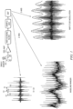
FIG. 1 is a partially-block, partially-pictorial, partially graphical depiction of an inventive structure and process for separating a respiration signal from heart and body motion and other signals using a single chest sensor. -
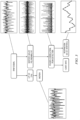
FIG. 2 is a flow diagram of an inventive structure and process for separating a heart signal from body motion and noise using a single accelerometer chest sensor and remarkable smoothing filter and residue generation, envelope-based noise rejection, and folded correlation. -
FIG. 3 is a partially-flow, partially graphical depiction of an inventive system and process separating a respiration signal, a heart signal and a body motion signal from each other using a single chest sensor. -
FIG. 4 is a flow diagram of an inventive system storage or process to inventively separate a respiration signal from a heart signal and using inter-beat intervals of the heart signal, with both the respiration signal and the heart signal substantially separated from body motion and noise signals. -
FIG. 5 is a flow diagram of another inventive system storage or process to inventively separate a respiration signal from a heart signal according to baseline wander method herein for respiration monitoring by a single inventively filtered accelerometer sensor. -
FIG. 6 is a flow diagram of another inventive system storage or process to inventively separate a respiration signal from a heart signal by amplitude modulation detection of peak heights of the heart signal. -
FIG. 7 is a block diagram of an inventive wireless system structure and process and including inventive structures and processes from the other Figures. - A miniature, high-sensitivity microelecromechanical system (MEMS) in a single, chest-
worn sensor 10 herein records signals including some related to heart sounds. (The term "heart sound" refers in an expansive way to a signal analogous to cardiac S1, S2, and/or heart murmur or other cardiac waveform features, obtained from the processing of accelerometer data or other sensor data, and not necessarily to an audible sound.) A major challenge of ambulatory monitoring is the corruption of heart signals by body motion artifact signals and the confusion of such signals. In some measurements, the chest acceleration signal as picked up by theaccelerometer 10 inFIG. 1 had a rather slow varying, but very strong (20-50 mv peak-to-peak) motion component. Riding on top of this motion signal was a higher frequency, but weaker (5-10 mv peak-to-peak), heart sound signal. Significant variability between subjects was observed in the frequency content of both the motion and the heart sounds. Also, signals for respiration, motion and heart sounds are not entirely frequency separable. Thus, more than simple digital band pass filtering is provided herein. - Example embodiments are described that separate and derive motion/activity, heart rate and respiration from a single signal derived from a single chest-worn sensor, such as a miniature Z-axis accelerometer sensor. Ambulatory measurement of respiration and cardiac activity can find wide application in home health monitoring of older adults and of patients with a history of cardiovascular, respiratory, and other conditions for which respiratory and/or cardiac monitoring are desired. Evaluating cardiovascular performance of patients in intensive care units (ICU) and hospital settings, in mobile ambulances, and at accident and trauma sites also calls for ambulatory cardiac and respiratory measurement and monitoring.
- Various example embodiments use a single miniature, chest-worn MEMS accelerometer and associated monitoring circuitry to measure and monitor respiration, motion and heart activity -- reflected by heart sounds -- as shown in
FIG. 1 . -
FIG. 1 illustrates example embodiments provided for ambulatory monitoring of heart rate and heart sounds, activity, body motion and respiration in a non-invasive and minimally obtrusive way. Here, a single sensor, such as with a MEMS accelerometer, extracts not only heart rate/heart sounds but also respiration in an ambulatory setting. Any signal is used that includes detectable heart sound signals from at least one sensor axis of the accelerometer sensor, or from two or more sensor axes. When a body motion signal component is included in the sensor signal, that body motion signal component is in some embodiments separated out or isolated and delivered as a useful output representing activity or motion as well. - Some advantages of various embodiments are extraction of three vitals (respiration, non-stationary bodily motion wander from activity, heart sounds/heart rate) from as few as a single sensor or signal capture component and a single signal. A miniature sensor embodiment taped on the chest provides a non-invasive and minimally obtrusive way to sense and monitor vital biomedical signals and physiological parameters in the presence of motion. Embodiments can be used with minimal inconvenience in ambulatory and continuous monitoring applications, and are very inexpensive and can be made into disposable patches and tapes, for instance.
- Some of the embodiments include a data acquisition/signal processing circuit having a special smoothing filter 130 (
FIG. 2 ) that tracks slow varying body motion signal wander or variation, and then removes the wander from the sensor-based signal to give a clean (motion-removed) biomedical signal of interest on a display unit. The smoothingfilter 130 involves a polynomial filter or comparably effective smoothing filter used directly or in a composite signal processing path. Some embodiments use asubtraction step 140 as inFIG. 2 to remove non-stationary motion artifacts reliably and robustly. Removing such artifacts makes the system more fully immune to sensor placement and contact variations on the chest that might arise when usingsensor 10. This provides a simple, yet effective way to reduce the impact of motion artifacts and allow the reliable detection of primary heart sounds and subsequent derivation of heart rate even when a person is walking while being monitored. In this way, motion signal removal or separation, and heart-sound signal detection and heart rate detection are facilitated. No secondary reference or noise source is needed, thus reducing complexity of system design. Embodiments of structure and method thus extract primary heart sound signals from chest-worn sensor (e.g., accelerometer) data in the presence of motion artifacts. - In some structure and process embodiments for removal of motion-related artifacts from biomedical signals, beneficial monitoring is provided, e.g., for either or both of two independent signal sources --
accelerometer 10 and ECG if used. Chest acceleration signals are collected in an ambulatory (walking) setting from real human subjects using a chest-wornaccelerometer 10 -- providing primary heart sounds signified as S1 and S2. Heart sound S1 includes audible sounds concurrent with tricuspid and mitral valve activity and shows on a seismocardiogram as a pulse bundle. Heart sound S2 is mainly associated with pulmonary valve and aortic valve activity. Structures and processes of the embodiments thus remove motion artifacts and facilitate the use of a single, miniature, chest-worn MEMS accelerometer to pick up heart activity and heart rate - derived from heart sounds -- from ambulatory subjects as shown inFIG. 1 . For testing, electrocardiogram signals are independently collected from the human subjects walking briskly or running on a treadmill -- providing signal components such as QRS from the ECG. - Process and structure embodiments can also be extended to other biomedical signals corrupted by motion wander - e.g., electrocardiogram (ECG), photoplethysmogram (PPG; signal from a pulse oximeter), electroencephalogram (EEG), electromyogram (EMG), impedance cardiogram (ICG) signals - or almost any other signal that might be affected by a separable wander. Thus, motion-related artifacts are removed from such other biomedical signals in products that can be produced by a manufacturer in volume.
- A polynomial smoothing filter 130 (e.g., a Savitzky-Golay filter, such as implemented electronically) digitally smoothes a given accelerometer-based data signal stream by approximating it within a specified data window by a polynomial of a specified order that best matches the data in the window in a least-squares sense. Here, the
electronic smoothing filter 130 fits the slower variations in body motion-induced components of the biomedical sensor-based signal and subtracts them as smoothed content from the biomedical sensor-based signal to leave behind what is called a residue signal. The residue signal provides a thus extracted, faster varying signal -- primarily the heart sounds and other cardiac activity, as well as some residual or remaining noise. Suchpolynomial filtering 130 preserves higher order moments around inflection points, or at extrema like peaks and troughs, that a digital moving average or low pass filter does not. In other words, the polynomial filtering better preserves features -- like local maxima and minima -- through a least-squares polynomial fit around each point. - In
FIG. 1 , a system embodiment has hardware that provides a measurement set-up and monitoring embodiment. A miniature (weight = 0.08 gram, size = 5x5x1.6 mm) triple axis, low-power, analog output MEMS accelerometer (e.g., STMicroelectronics Part No. LIS3L02AL) is taped onto the chest (e.g., a few inches to the left of the sternum along the third or fourth rib). (Taping the accelerometer sensor or using a chest band presses the accelerometer sensor to or against a bare or shaved portion of the chest and efficiently couples chest acceleration to the sensor.) An acceleration signal corresponding to the cardiac activity is captured along the Z-axis - the dorsoventral direction orthogonal to the plane of the chest. The chest acceleration signal is AC-coupled with a 3 Hz cutoff and amplified with a gain of 100 and low pass filtered (for anti-aliasing) through a three-stage, five-pole Sallen-and-Key Butterworth filter with a 1kHz corner frequency. A commercial quad operational amplifier (op amp) package (e.g., Linear Technology Part No. LT1014CN) is used for the analog front-end. The accelerometer signal is then sampled at 10,000 Samples/sec using a data acquisition card (e.g., as available from National Instruments, Austin, Texas, USA) and captured and stored on a computer using MATLAB software (Version 2007b, The Mathworks, Natick, Massachusetts, USA). The AC coupling with approximately 3 Hz cutoff, which is a noncritical roll-off frequency, is provided, for example, by a series coupling capacitor C coupled to an input resistance established for the amplifier. For testing, a reference ECG (lead II) may be provided and acquired simultaneously in a three electrode (single lead) electrocardiogram ECG amplifier configuration as a standard of reference in order to compare with the accelerometer-derived cardiac signal for the evaluation of the performances of the heart rate extraction from the accelerometer signal. - In
FIG. 2 , for detection of primary heart sounds and cardiac activity, the acceleration signal is digitally low pass filtered in astep 110 at 50 Hz (e.g., using a 3326 tap digital FIR filter with a steep 80 dB roll-off over 20 Hz) and decimated in astep 120 by a factor of 10. (Roll-off frequency less than 60 Hz attenuates 60 cycle USA power line interference with biomedical signals of interest, and roll-off may be made less than 50 Hz for applicable countries using 50 Hz. While the roll-off frequency could be made higher, this FIR filter also desirably attenuates white noise above the frequency range of the signals being monitored.) Also in aPhase 1, a high order Savitzky-Golay (S-G)polynomial smoothing filter 130, using 28th order and 401 point frame, is used to capture the relatively slow-varying motion wander and leave out the more rapidly varying heart sound signal components. (Matlab syntax for such filter is g = sgolayfilt(X,28,401), where g is the filter output and X is a latest input column vector of 401 sample values of windowed data.) In aPhase 2, the smoothingfilter 130 output is subtracted in astep 140 from the decimated LPF output to obtain heart sounds S1 and S2. A folded correlation process in astep 160 then enhances and strengthens the polynomial filtered S1/S2 peaks in the motion-removed acceleration signal. Then the location of the peaks is threshold-detected in astep 170 using an electronic amplitude-based peak picking process, and the selected peaks are counted in astep 180 to calculate heart rate HR - Low pass filtering (LPF) below 50Hz is used in some of the examples because most of the desired signal power lies in that range and in general LPF with some roll-off frequency below about 100 Hz in many of the embodiments avoids making the bandwidth so wide as to encompass and integrate a substantial or undue amount of sensor noise (thermal, white spectrum). In case LPF with a roll-off frequency above power-line frequency is used, then some embodiments also include notch-filtering for power-line frequency rejection. Another embodiment extracts satisfactory S1-S2 heart signals from raw motion-affected accelerometer Z-axis data by low pass filtering with corner at 100 Hz and then Savitzky-Golay filtering at 20th order, followed by subtraction of the S-G signal from the LPF signal, and followed further by signal enhancement. It appears that polynomial filtering of motion-affected LPF accelerometer signals, using polynomial filtering on the order in a range of approximately 20th order or higher order to at least over 30th order, is satisfactory for obtaining heart signals as a residue by subtraction of the polynomial filtering output from the LPF signals. Using polynomial fits at such orders successfully captures both coarser and finer motion effects. The smoothing filter in some embodiments can be lower order as well, and may obtain good results even with a 1st-order polynomial in case of some window sizes and applications. Also, lower order polynomial filtering is contemplated and found useful as discussed later hereinbelow. Using a number of points at least approximately half again (1.5 or more times) an order of the polynomial and even substantially higher than that, in some of the embodiments, is believed to help to reduce noise.
- The smoothing
filter 130 ofFIG. 2 is configured based on a specified order M and frame size (number of sample points N). For instance, a Savitzky-Golay polynomial smoothing filter is used in some embodiments to best approximate the acceleration signal in the least-squares sense to capture the motion-dependent baseline-wander. In some embodiments, the smoothing filter is implemented in flash memory of a local processor such as a belt-worn unit or provided in a home network gateway or clinic office network gateway, or cell phone or otherwise. - The matter of selecting and or finding feasible and optimum values for order M and window length (Nw in points, tw in time) for the polynomial smoothing filtering is discussed next. In general for a fixed window length, Nw, a higher order polynomial will fit the high frequency components of the streaming data better. For a given order M, a shorter window of time will allow fitting the high frequency component better.
- A way to approach the optimization problem estimates the inherent order of the low-frequency component and picks the smallest window that satisfies the condition that Nw > M+1 and Nw is odd (i.e., Nw = 2N+1). The smaller the window size Nw, the smaller will be the number of taps of the multiply-accumulate filter process implementing the smoothing filtering. For an accelerometer signal in some applications, order M=1 and window size Nw =3 (sampling frequency is 1000 Hz). In some examples herein, higher orders M and window widths Nw are shown.
- In
FIG. 2 , motion, heart sounds and heart rate are electronically separated and ascertained fromaccelerometer 10 data using the following steps: a)low pass filtering 110 and decimating 120 the accelerometer data; b) Savitzky-Golay filtering 130 to fit the relatively lower frequency motion data; c) subtracting 140 the output of the Savitzky-Golay filter from the low pass filtered accelerometer data (from step a) to obtain the heart sounds; d) performing 160 folded correlation to enhance the primary heart sounds (S1 and S2) peak locations; and e) peak picking 170 to count the number of S1 peaks in a predetermined or configured segment (time interval) and counting 180 the heart rate (HR) in beats per minute (BPM). - Note that the term 'decimation' refers to any process of regularly removing samples from a sample stream, or passing one sample in every nD samples as decimation parameter, and can (but does not necessarily) refer to removing all but one sample in ten. Thus, if a sample/ADC delivers fs samples per second, then a decimation process delivers a decimation frequency substantially fS/nD samples per second. If a window period is tw seconds, then the number of points Nw = 2N+1 in the window is Nw = 1+fs tw / nD. The window period tw may be selected by considering the time period over which the particular features and behavior of interest are to be obtained by the filtering from the signal. The sampling frequency fs may be selected with cost, physical size and complexity of anti-aliasing in mind (low pass filter AAF at 0.5fs or less situated ahead of sampling fs). The sampling frequency fs may be set substantially greater than the Nyquist frequency for sampling the AAF (anti-alias filter) output. The decimation parameter nD is then selected, firstly, to yield a decimation frequency fS/nD that is sufficiently high relative to the, e.g., 50 Hz low pass filter LPF following the sampling/ADC circuit to provide effective operation of that LPF. Secondly, the decimation parameter nD is also selected to yield a number Nw of window points that is sufficiently high relative to the selected order M of the filter to keep filter noise low while having the Nw window points being sufficiently low in number as to introduce only so many filter computations as needed to achieve satisfactory filtering of the signal stream in the window. The filter computations are related to the product of the number Nw of points per window multiplied by a rate number rw of windows processed per second. If rw = Nw/ tw, the computations are proportional to Nw2 / tw , which may motivate fewer window points and longer window times in some energy-saving and lower cost processor applications.
- Mathematically expressed electronic processes are described in further detail below for preparing various electronic embodiments with smoothing filters for various ways of motion extraction in
step 130 and any other purpose to which their advantages commend their use. They are appropriately partitioned into offline and real-time online electronic processes in such embodiments. The notation ∥(x-Ab)∥ in Equation (1) below signifies the sum of squared differences between the [(2N+1)x1] respective data stream vector sample points or stream components and the (2N+1) respective estimates of those stream components provided by multiplying a [(2N+1)xM] transform matrix A times a [Mx1] vector of transform coefficients bj. The number of transform coefficients bj is M, and they form a [Mx1] vector b. A gradient∇ is the [Mx1] vector of first partial derivatives with respect to the transform coefficients bj. The number M of coefficients bj is called the order, and if the number of transform coefficients bj is M, then the order of the process is M. The [MxM] matrix of second partial derivatives with respect to the transform coefficients bj is signified by ∇ ∇. The filter procedure involves, and in effect forms, a coefficients change coefficient vector Δ b for updating an initial transform coefficient estimate b=0 (i.e., all coefficients initialized to zero). This procedure pre-multiplies the matrix of second partial derivatives times the negative of the gradient to obtain that transform coefficients change vector:
- Equation (2) represents the result of performing the calculus operations represented by Equation (1). (Some embodiments transmit the coefficients b from Equation (2) to a remote site for record storage and further analysis, since they effectively compress much of the information in the data window. If coefficients are to be transmitted, the [Mx(2N+1)] matrix (ATA)-1 AT is pre-computed and then multiplied by each data window locally on the fly. Other embodiments omit such compression and/or transmission, or only do it locally on remote command, and thereby save some power and processing complexity.)

- In the special case of a polynomial transform process, a matrix of indices is raised to powers, wherein the jth column element Anj in the nth row of transform matrix A is raised to a power: n j. In other words, for the 2N+1 different values of n from -N to +N in the window of a data stream X(i+n), the transform finds a set of coefficients bj for a well-fitting power series to approximate all the values. Such a power series in general is

- Savitzky-Golay filtering outputs as the filter output g(i) for the window indexed i the value of bo estimated by Equation (2) for each data window, and successively window-by-window for successive indices g(i). Rows of matrix A are orthogonal when the inner product is zero for any pair of different ones of them. These rows are illustrated in Table 1, below. The rows of values Anj in matrix row n are non-orthogonal for the example of a polynomial transform. ("^" signifies raising to a power) .
Table 1: Arrangement of Matrix AT Power m (Order M) Points 0 1 2 3 ... M n=-N: [1 (-N) (-N)^2 (-N)^3 ... (-N)^M] ... n=-1: [1 -1 1 -1 ... (-1)^M] n=0: [1 0 0 0 ... 0^M] n=1: [1 1 1 1 ... 1^M] ... n=+N: [1 N N^2 N^3 ... ... N^M]. - Next, the process finds an estimated data stream


- Sometimes a mathematical presentation of Savitzky-Golay filtering regards the window as multiply-added by a set of (2N+1) filter coefficients c(n). Here, a [1x(2N+1)] filter coefficient vector C is introduced so that


- In Equation (8), an alternative notation CI equivalent to Equation (6) post-multiplies Equation (7) by a [(2N+1)×(2N+1)] identity matrix I and designates each of the columns of that identity matrix I as [(2N+1)×1] unit vectors εn. The phrase 'unit vector' for εn means a [(2N+1)×1] vector of all zeroes except for a one (1) at the nth row position. Furthermore, only the matrix inversion computations to form the first row of inverse matrix (ATA)-1 are relevant and are performed, considering the pre-multiplication by [1xM] row n=0 vector [1 0 0...0]. Thus, the filter coefficients are also equivalently expressed in the notation of Equation (8), which is equivalent to Equation (7).

- The Savitzky-Golay filter does a local polynomial fit in a least square sense. For a given input variable data window x(i+n) and window of length 2N+1 and chosen polynomial degree M, the filter output is given by g(i). Filter coefficients c(n)-
2N+ 1 of them-are computed, e.g. off-line, by electronic operations represented by Equation (7) or (8) and loaded into flash memory of a small signal processing unit either worn on the person or provided nearby and coupled wirelessly to theaccelerometer sensor 10. The signal processing unit suitably has a digital signal processor circuit such as processor 220 that electronically performs multiply-accumulates (MACs) represented by Equation (6) according to a stored program accessing the filter coefficients c(n). - Some other embodiments use windows that are not centered around the value at index n used as the output (e.g., n=0). A variety of choices of matrices A are possible instead of the particular polynomial transform matrix shown in Table 1. The skilled worker chooses the desired transform, the window (frame) size (e.g., 2N+1) and the order M. Also, note that g(i) output of a first filter procedure produces a data stream that itself can be windowed as represented by column vector g1(i2) in Equation (9B). Accordingly, some embodiments represented by Equations (9A), (9B) cascade two lower order filters of Equation (4) and use straightforward technique to minimize the electronic processing complexity of the computations in implementation. The transform matrices A1 and A2 can be the same or different, the window sizes (2N1+1) and (2N2+1) can be the same or different, and the orders M1 and M2 can be the same or different, all these choices being independent of each other.


- Some embodiments may also apply to the SG process a diagonal weighting matrix W which is all zeroes in a [(2N+1)×(2N+1)] matrix except for weights down the main diagonal. The weights can, for instance, be one at the middle of the diagonal and diminish symmetrically in value farther from the middle of the diagonal. Equation (1) is replaced by:

- Then the electronic process represented by Equation (5) for the output instead is:

- Some other embodiments store and average a set of values from the transform output of Equation (4) from different windowed segments of the data stream X. This approach, roughly speaking, performs several filters in parallel and averages them in an offset manner. All the values represent a reconstructed value corresponding to a same instant of time (i+n) = t, and note that this approach not only uses the n=0 row to approximate bo but also uses the transform approximations to the other coefficients that are available from Equation (3). The electronic processor 220 (and/or 240) performs the electronic process as represented by Equation (12), where X'(i+n) is from Equation (4).

- In view of the analysis herein, it is emphasized that other types of processes can be alternatively selected according to the teachings herein, whether they are called Savitzky-Golay or not. The skilled worker sets up a test bench with library accelerometer-based waveforms and then makes the transform matrix choices, choice of number of points (2N+1), and choice of order-value M, either manually or by an automated process. The filtering choices are tested either by visual inspection of a display of output from
FIG. 1 process or by automated process according to metrics of false negatives and false positives, etc. as described herein. Transform matrix A values, and values of (2N+1) and M, 2N1+1, etc. for one or more such filter processes having favorable metrics are then loaded into the monitoring device flash memory or hard drive and executed in real time on processor 220 (or 240). - A transform for an embodiment approximates an actual data stream vector x(i+n) and produces an output signal stream that follows the heart sound peaks well over time in response to a data stream X herein derived from a body-worn accelerometer. Some embodiments have reduced processing complexity by using low enough frame size (2N+1), order M and/or using an efficient transform matrix A to achieve desired performance for the purposes for which the monitoring is intended. The same transform is desirably low-complexity and well-performing over numerous patients, accelerometers and their positioning on the body, and in different environments of use, such as clinic, hospital, home, exercise venue, etc.
- In envelope-based
noise rejection 150, an amplitude envelope is generated. The residue signal stream r(i) = x(i)-g(i) of ofFIG. 2 has some remaining noise from subtractingstep 140 that subtracts the smoothing filter output g(i) from the LPF-supplied input x(i). An envelope is fitted to the residue as inFIG. 1 . The amplitude-based processed output R(i) is derived from the envelope-fitted residue r(i). The noise n(i) near the horizontal axis is substantially reduced. Operations for this process suitably use an envelope-related variable gain function. Alternatively, the circuit and/or process is arranged to generate zero signal output when the envelope is below a low threshold that still passes the peaks. - In folded
correlation 160, an input data stream of residue r(i) = x(i)-g(i) , or envelope-processed residue R(i) comes to the folded correlation process. Recall that g(i) is the output of the smoothing filter such as represented by Equation (6) or from a buffer memory for it. Processed filtered residue R(i) is windowed by a further data window (also called a frame) of length 2N2 +1 (with points accessed by an index n=0,1,2... N2). - The output fc(i) of the folded correlation is given by Equation (13):

- The digital data stream for heart monitoring residue signal samples R(i) from the smoothing filter subtraction is successively processed in overlapping frames indexed i. In general, the value of 2N2 + 1 is selected to be approximately the width tw of a desired signal event (e.g., an S1, S2, or R-wave). For example, S1 is typically about 100-150 milliseconds long. If the decimated sampling frequency fs is 1000 Samples/sec, the value of 2N2 + 1 is established, e.g., as an odd number between 101 and 151, and N2 is some number between 50 and 75 inclusive. Thus,

- The Folded
Correlation 160 in another example has a frame size of 7 at with the 1000 samples/sec that resulted from decimation. The peaks corresponding to S1 and S2 in the motion-removed acceleration signal are thus strengthened and are then peak-detected instep 170 for counting 180. In some embodiments, the value of N2 is configured in flash memory, and can be selected or altered by a local or remote operator. In the electronic foldedcorrelation process 160 represented by Equation (13), the heart monitoring residue samples R(i + N2 - n) from the later half of each frame are folded around the center heart monitoring sample R(i) in the frame and multiplied by dot product (sum of products in Eq. (13)) with heart monitoring residue samples R(i - N2 + n) in the earlier half of each frame. The result of the dot product is a folded correlation output signal stream fc(i) corresponding to instant i of the input residue signal stream R(i) in the center of the frame. Succeeding thresholding passes the S1 peaks and counts them. Robust detection of primary heart sounds and heart rate from a chest-worn accelerometer is thus achieved in the presence of interfering motion artifacts. - In
FIG. 3 , a respiration waveform is obtained, for example, by a monitoring device embodiment ofFIG. 1 and its process embodiment. The process inFIG. 3 receives the raw signal stream from the analog-to-digital converter (ADC) ofFIG. 1 and then first separates the heart sounds from the composite signal from the sensor using Savitzky-Golay (S-G) polynomial fitting, followed by folded correlation and peak detection to deliver the S1 heart signal peaks. The heart rate is counted in response to the peak detection to provide a heart rate signal output. Concurrently, the respiration is monitored by then measuring the successive times, called the inter-beat intervals or S1-S1 intervals, between heart beats - beat by beat. The variation in the measured inter-beat interval over time thus represents respiration because it is respiration-dependent and substantially independent of non-respiratory gross body motion. The monitoring device thus delivers as a respiration waveform that substantially represents the inter-beat interval varying over time. Further respiration processing counts the breathing rate and delivers a resulting breathing rate output, and derives and outputs any other useful information. - Detection of respiration from the inter-beat interval may involve a phenomenon called respiratory sinus arrhythmia RSA, which is possibly responsive to respiration-related and other intrapleural or intra-thoracic pressure changes. In the meantime, the motion signal is extracted either from the S-G
polynomial smoothing filter 130 as inFIG. 2 or by a low pass filter LPF, such as a digital finite impulse response (FIR) filter with corner frequency at 2Hz as shown inFIG. 3 . - In
FIG. 3 , post-processing of the motion signals is applied to monitor and deliver waveforms representing average activity level over time, monitor walking gait and other motions, and detect a fall if one were to occur. Consequently, deriving motion or activity from an accelerometer is important, such as by the present embodiments. For instance, average activity level can be generated as the root-mean-square (RMS) of the motion waveform measured over an hour and output hour by hour. Walking gait can be derived from the Z-axis alone or in combination with signal streams from other accelerometer axes with respiration subtracted out. A fall sensor embodiment includes a peak detection of an unusually high-magnitude acceleration peak which stands out from any recent or subsequent neighbor peaks in a predetermined window of time such as +/-15 seconds. - Process embodiments as in
FIGS. 1 and3 separate motion signal components from an accelerometer sensor signal to cleanly and robustly extract heart sounds and also respiration (derived from heart sounds) in the presence of motion and activity, and further to deliver a motion/activity signal. In some embodiments, motion-based gating is performed to reject signal frames in the event that the motion/activity level is unusually high and does not permit reliable detection of heart rate or respiration or some other derived signal under a given detection process. The monitoring device measures gross body motion such as to sense and monitor activity and can provide a useful index of a person's level of activity over a period of time, and facilitate inferences about the person's lifestyle and metabolic index -- jointly with ECG-derived heart rate. Gait recognition by accelerometer-based motion monitor aids biometric assessment and can identify signs of or precursors to a dangerous fall. Also, using the accelerometer-based motion monitor as an indicator of sudden, high-magnitude acceleration can additionally identify signs of or precursors to a dangerous fall, as well as a fall itself. - In
FIG. 3 , the signal obtained during motion from the chest-worn accelerometer is digitally low pass filtered at 2 Hz (using a digital FIR filter) to extract the slowly varying baseline wander due to motion. For at least some cases of body motion as well as the body at rest, the respiration signal is well decoupled in frequency from the low-frequency body motion signal and is thus digitally low pass filtered to successfully extract the respiration signal. -
FIGS. 4, 5, and 6 respectively show three processes or methods of electronically generating respiration signal outputs from a sensor input. In various embodiments, these processes are used either individually, or in pairs, or a combination of all. Some embodiments as illustrated inFIGS. 1 ,3 and4 derive respiration from an accelerometer sensed-and-residue-detected variation in the S1-S1 interval during motion. - In
FIG. 4 , a process embodiment obtains the heart sound signal at astep 310 by removal of motion-dependent wander inPhase 2 ofFIG. 2 . The heart sound peaks are reinforced through FoldedCorrelation 320, andpeak detection 330 is performed to detect the S1-S1 peaks. In astep 340, the S1-to-S1 interval (or S2-to-S2 interval) is repeatedly computed beat-by-beat to electronically obtain data values of successive inter-beat intervals. These data points are interpolated in astep 350 to yield a continuous respiration waveform ofFIG. 3 . - In
FIG. 5 , another process embodiment is called the baseline wander method herein for respiration monitoring by a single accelerometer sensor. This process in astep 380 operates on the raw accelerometer ADC signal input from a person at rest by low pass filtering it with a filter cutoff frequency at about 2 Hz, or otherwise selected, e.g., with LPF cutoff in a range of about 1 Hz to about 3Hz. A waveform called 'baseline wander' thus obtained as an electronic respiration signal at astep 390. In other words, breathing periods of about half a second or more are passed, so that not only resting breathing periods of a breath every two or three seconds are detected, but also breathing periods under stress or after exercise down to about a third or half a second are detected. Shorter period signal variations in the accelerometer are suitably obtained from the S-G filter smoothing or by other types of filtering to represent body motions other than respiration. - In
FIG. 6 , a further embodiment for respiration monitoring by asingle accelerometer sensor 10 obtains the heart sound signal at astep 410 by removal of motion-dependent wander inPhase 2 ofFIG. 1 . Foldedcorrelation 420 reinforces heart sound peaks, andpeak detection 430 detects the amplitude modulated S1 peaks. Instead of (or in some embodiments in addition to) inter-beat interval measurement as inFIG. 4 , the successive S1 peak amplitudes (or S2 peak amplitudes) in astep 440 are repeatedly measured electronically beat-by-beat inFIG. 6 to electronically obtain data values of successive heart sound peak amplitudes. These data values are interpolated in astep 450, such as by linear or quadratic or other interpolation, to yield a continuous respiration waveform. - Various respiration parameters are obtained by finding various values on the respiration waveforms and differences and trends therein. Respiration rate is measured as the number of cycles of inhalation and exhalation in a given time window (e.g., one minute). Averaging and signal fusion methods/algorithms robustly derive respiration rates from multiple parameters. How deeply the person is breathing is represented by an average of the difference between successive values of inhalation peak and exhalation trough in a given time window (e.g, one minute). Averages and trends in the inhalation peaks and/or exhalation troughs are readily calculated and displayed respectively.
-
FIG. 7 shows awireless system embodiment 600 for a respiration and cardiac monitoring system including various remarkable device or component embodiments. Some embodiments are wired embodiments, andFIG. 7 shows a wireless embodiment. Anaccelerometer sensor 610 and its electronic circuit also have a Bluetooth or other short range wireless modem wirelessly coupled to another shortrange wireless modem 622 that is coupled via a streaming data andcontrol interface 624 to a data acquisitionsignal processing unit 620. Further, modems 640.2 and 670 for wireless transmission and reception remotely are provided at each of two locations so that the data acquisitionsignal processing unit 620 communicates via its modem 640.2 to the remote wireless transceiver unit ormodem 670. Thelatter modem 670 is coupled to be one or more display units 650.i and their storage unit(s) 660.i. In this way, telemedicine applications are supported. The acquisitionsignal processing unit 620 and its modem 640.2 are suitably provided in a residence or ambulance or on the person or in a wheelchair or gurney. Thewireless transceiver 670 and display unit(s) 650.i are suitably provided in a clinic, hospital, medical monitoring center or otherwise. Either or both ends of the wireless system may be mobile, such as one example of a modem 640.3 and alert/processor/display 680 when a professional in a vehicle is urgently needed to review data coming in from a residence or another vehicle in case of emergency and to respond with instructions. - In
FIG. 7 , combinations with further processes, circuits and devices for automatic cautionary responses, warnings, and/or automated monitored therapeutic responses are contemplated. Upon occurrence of undue excursions of one or more measured parameters or relationships among parameters detected bysignal processing unit 620, theremote processor 670 alerts any one or more of medical professional, patient, caregiver, and/or family member via a modem 640.3 and alert/processor/display unit 680 by sending a cellular telephone call and/or other voice call or message and/or written alert such as an automatic e-mail. The alert system suitably provides for acknowledgement by any of the recipients. Also, another modem unit 640.1 is suitably provided and coupled to a telemedicine therapeutic orassistive device 690 for assisting the patient in some pharmacological, informational, or physically assistive way by administering a medicine, or adjusting a dosage or otherwise. In case of excursions that indicate an extreme medical emergency, the data acquisitionsignal processing unit 620 may be permitted to locally control the therapeutic orassistive device 690 temporarily and in a maximally-safe way until remote commands are received or first responders can arrive. Mere removal or inadvertent detachment of theaccelerometer 610 from the chest is distinguished by theelectronic processing 620 from affirmatively detected excursions of measured signals and parameters. Regarding telecommunicated care (tele-care) assistance, such assistance is suitably rendered in some physical way in response to the real-time accelerometer sensor 620 data by activating motorized apparatus comprehended bydevice 690 such as to adjust a motorized bed, or move a scooter into proximity for patient use, or servomechanically actuate and flush a toilet unit, or open a tub drain to empty a tub, or some other assistance. - Types of embodiment, among others, can form: 1) a patient-worn medical-sensor and/or therapeutic device that is wired or has a wireless modem; or 2) a patient-worn signal processing and modem module on a belt clip that connects or wirelessly couples to such a sensor and wirelessly couples to a premises gateway or directly transmits to a remote location; or 3) a sensor, signal processor, memory, and modem together in a micro-miniature device that is taped to the chest and communicates to a router or gateway locally, and the latter communicates remotely; or 4) a local router or gateway that includes signal processor, memory, and multiple types of modem to communicate with the sensor and separately communicate remotely, such as in a patient home-based system to telecommunicate to clinic or hospital; or 5) a complete medical clinic system.
- Peripherals and interfaces can include a UART (universal asynchronous receiver/transmitter) data interface and MCSI (multi-channel serial interface) voice and data wireless interface for an off-chip IEEE 802.15 (Bluetooth and low and high rate piconet, Zigbee, and personal network communications) for a wireless circuit. The Bluetooth or Zigbee wireless interface is useful for receiving from and controlling the accelerometer sensor and its associated analog circuitry and digital to analog-to-digital converter ADC in
FIG. 1 . In arrangements including ECG electrodes and/or a chest microphone, the analog circuitry at the taped-on sensor unit also includes couplings from such pickup elements to the Bluetooth or Zigbee short distance transceiver from the chest sensor. - An
accelerometer sensor 10 and transmitter, transceiver, or transponder chip can be firmly mounted on a thin, resilient, light-weight plastic support plate with round smoothed or flanged coin-sized periphery and comfortably affixed by adhesive tape to chest. The Z-axis of the accelerometer is perpendicular to the plane defined by the plastic support. The chip may harvest power from an interrogation signal, or may have a small battery on the plastic support electrically connected to supply low power to the chip, such as an MSP430™ low power processor from Texas Instruments or other processor and a short distance wireless transmitter. Also, a wireline interface with a miniature wireline female connector can be electrically connected to a wireline interface in the chip, such as for USB (universal serial bus). - In some embodiments, accelerometer signals from all three axes are suitably processed to electronically double-integrate the acceleration to determine the location of the person wearing it and successively estimate a varying physical location from the same signal input of a signal interface as a cue to the person who is visually impaired, to caregiver, and to a family member. Since the person is likely to have been in bed overnight, the processing determines the location of the person during the day by double-integrating the acceleration starting from initial conditions of position initially at the bed location, and zero initial vector velocity. An electronic compass can be physically included into the sensor assembly for supporting location-based services by the sensor assembly. Some embodiments have a printed wiring board (PWB) for an applications processor coupled to a modem, together and a user interface if used. SDRAM and flash memory storage coupled to the system can provide tables, configuration and parameters and an operating system (OS), protected applications (PPAs and PAs), and other supervisory software. Adjusted parameter(s) are loaded into the flash memory or otherwise, and components are assembled on PWB to produce resulting system units.
- Processing circuitry comprehends digital, analog and mixed signal (digital/analog) integrated circuits, ASIC circuits, PALs, PLAs, decoders, memories, and programmable and nonprogrammable processors, microcontrollers and other circuitry. Couplings and connections can be ohmic, capacitive, inductive, photonic, and direct or indirect via intervening circuits or otherwise as desirable. Flow diagrams and block diagrams are each interpretable as representing structure and/or process.
- Those skilled in the art will appreciate that many other embodiments and variations are also possible within the scope of the claimed invention. Embodiments having different combinations of one or more of the features or steps described in the context of example embodiments having all or just some of such features or steps are also intended to be covered hereby.
Claims (16)
- A respiration monitoring device for use with a signal input, comprising:a signal interface to receive and convert the signal input to an electronic form for further processing; andan electronic circuit fed by the signal interface and comprising a smoothing filter, and operable to filter an acceleration signal in a manner to obtain a slow wander signal, to subtract from the acceleration signal the slow wonder signal to obtain a heart sound signal, and to derive a respiration signal from the heart sound signal; and
wherein the electronic circuit is further operable to subtract the respiration signal from the slow wander signal to produce a substantially non-respiration body motion signal. - The device of claim 1, further comprising an accelerometer for application to the chest and coupled to deliver the signal input; whereby acceleration is possible due to both non-respiratory body motion and respiration.
- The device of claim 2, wherein the electronic circuit further includes a smoothing filter operable to derive the heart sound signal to represent heart pulses as a residue of the smoothing filter.
- The device of claim 3, wherein the electronic circuit is operable to derive respiration rate based on the respiration signal.
- The device of claim 4, wherein the electronic circuit further includes a nonvolatile memory that has instructions and filter coefficients for directing operations of the electronic circuit.
- The device of claim 5, wherein the electronic circuit further includes an electronic processor operable to perform an interpolation augmenting and based on the respiration signal for representing the respiration responsive to an accelerometer.
- The device of claim 6, further comprising an output modem circuit coupled to the electronic circuit, and operable to transmit signals representing at least some of the information generated by the electronic circuit.
- The device of claim 6, wherein the electronic circuit is further operable, independent of the heart signal, to separate a first signal component for body motion responsive to an accelerometer above approximately 2 Hz from a second signal component for respiration responsive to the accelerometer below approximately 2 Hz.
- The device of claim 8, further including a respiration display circuit coupled to the electronic circuit.
- The device of claim 8, wherein the electronic circuit is further operable to monitor for an unusually high-magnitude peak in the non-respiration body motion signal and, in such case, supplying a signal representing a possible fall of a user.
- The device of claim 8, wherein the electronic circuit is further operable to derive a first signal representing heart pulses having amplitude modulation, and further to generate a second signal that varies responsive to the amplitude modulation to represent respiration.
- The device of claim 11, wherein the electronic circuit is further operable to process one or more of the respiration signal, non-respiration body motion signal and heart signal in order to detect coughing.
- The device of claim 11, wherein the electronic circuit is further operable to derive walking gait from the non-respiration body motion signal.
- The device of claim 11, wherein the electronic circuit is further operable to successively estimate a varying physical location from the same signal input of the signal interface.
- The device of claim 1, wherein the electronic circuit further includes an electronic processor operable to perform an interpolation augmenting and based on the respiration signal for representing the respiration responsive to an accelerometer.
- The device of claim 1, wherein the electronic circuit is further operable, independent of the heart signal, to separate a first signal component for body motion responsive to an accelerometer above approximately 2 Hz from a second signal component for respiration responsive to the accelerometer below approximately 2 Hz.
Applications Claiming Priority (5)
| Application Number | Priority Date | Filing Date | Title |
|---|---|---|---|
| US26233609P | 2009-11-18 | 2009-11-18 | |
| US26233109P | 2009-11-18 | 2009-11-18 | |
| US12/861,882 US20110066041A1 (en) | 2009-09-15 | 2010-08-24 | Motion/activity, heart-rate and respiration from a single chest-worn sensor, circuits, devices, processes and systems |
| EP10832160.5A EP2501277A4 (en) | 2009-11-18 | 2010-11-18 | Apparatus and methods for monitoring heart rate and respiration |
| PCT/US2010/057180 WO2011063092A1 (en) | 2009-11-18 | 2010-11-18 | Apparatus and methods for monitoring heart rate and respiration |
Related Parent Applications (1)
| Application Number | Title | Priority Date | Filing Date |
|---|---|---|---|
| EP10832160.5A Division EP2501277A4 (en) | 2009-11-18 | 2010-11-18 | Apparatus and methods for monitoring heart rate and respiration |
Publications (1)
| Publication Number | Publication Date |
|---|---|
| EP4154805A1 true EP4154805A1 (en) | 2023-03-29 |
Family
ID=60160347
Family Applications (2)
| Application Number | Title | Priority Date | Filing Date |
|---|---|---|---|
| EP22203161.9A Pending EP4154805A1 (en) | 2009-11-18 | 2010-11-18 | Apparatus for monitoring heart rate and respiration |
| EP10832160.5A Withdrawn EP2501277A4 (en) | 2009-11-18 | 2010-11-18 | Apparatus and methods for monitoring heart rate and respiration |
Family Applications After (1)
| Application Number | Title | Priority Date | Filing Date |
|---|---|---|---|
| EP10832160.5A Withdrawn EP2501277A4 (en) | 2009-11-18 | 2010-11-18 | Apparatus and methods for monitoring heart rate and respiration |
Country Status (3)
| Country | Link |
|---|---|
| EP (2) | EP4154805A1 (en) |
| JP (1) | JP5889197B2 (en) |
| WO (1) | WO2011063092A1 (en) |
Families Citing this family (14)
| Publication number | Priority date | Publication date | Assignee | Title |
|---|---|---|---|---|
| US20110245688A1 (en) * | 2010-03-31 | 2011-10-06 | General Electric Company | System and method of performing electrocardiography with motion detection |
| US20130338460A1 (en) * | 2012-06-18 | 2013-12-19 | David Da He | Wearable Device for Continuous Cardiac Monitoring |
| BR112015000337A2 (en) * | 2012-07-12 | 2017-06-27 | Koninklijke Philips Nv | method for determining at least one maternal physiological parameter other than heart rate and respiratory rate; signal monitoring unit; fetal monitoring system; and provided software module to perform the method steps |
| JP6441914B2 (en) * | 2013-06-19 | 2018-12-19 | プレコルディール オサケユイチア | Method and apparatus for determining information representative of a cardiac disorder |
| CN104434064B (en) * | 2014-11-26 | 2017-01-11 | 中国科学院计算技术研究所 | Method for processing and tracking heart rate and respiration rate signals and a system thereof |
| CN106999065B (en) * | 2014-11-27 | 2020-08-04 | 皇家飞利浦有限公司 | Wearable pain monitor using accelerometry |
| WO2016094417A2 (en) * | 2014-12-08 | 2016-06-16 | Jabourian Artin Pascal | Determination of unsuspected arrhythmia based on extra cardiac signs |
| BR112017015888A2 (en) * | 2015-01-28 | 2018-03-27 | Koninklijke Philips N.V. | device, electromyographic patch, and method for determining and / or monitoring an individual's respiratory effort; and computer program |
| IL239113A (en) | 2015-06-01 | 2016-12-29 | Elbit Systems Land & C4I Ltd | System and method for determining audio characteristics from within a body |
| US10722182B2 (en) * | 2016-03-28 | 2020-07-28 | Samsung Electronics Co., Ltd. | Method and apparatus for heart rate and respiration rate estimation using low power sensor |
| EP3463073A4 (en) * | 2016-06-06 | 2019-12-18 | Tosense, Inc. | Physiological monitor for monitoring patients undergoing hemodialysis |
| EP3257441A1 (en) * | 2016-06-16 | 2017-12-20 | Acarix A/S | Quantitative seismocardiography |
| EP3681389B1 (en) | 2017-09-15 | 2023-04-05 | Cardiac Pacemakers, Inc. | Direct heart sound measurement using mobile device accelerometers |
| JP7177443B2 (en) * | 2018-11-09 | 2022-11-24 | ヘルスセンシング株式会社 | Biological vibration signal detector |
Citations (4)
| Publication number | Priority date | Publication date | Assignee | Title |
|---|---|---|---|---|
| US20040111025A1 (en) * | 2002-12-04 | 2004-06-10 | Avniash Gopal B. | Method and system using a non-electrical sensor for gating |
| US20050240087A1 (en) * | 2003-11-18 | 2005-10-27 | Vivometrics Inc. | Method and system for processing data from ambulatory physiological monitoring |
| US20080275349A1 (en) * | 2007-05-02 | 2008-11-06 | Earlysense Ltd. | Monitoring, predicting and treating clinical episodes |
| US20090105556A1 (en) * | 2007-09-28 | 2009-04-23 | Tiax Llc | Measurement of physiological signals |
Family Cites Families (6)
| Publication number | Priority date | Publication date | Assignee | Title |
|---|---|---|---|---|
| KR20020003932A (en) * | 2000-06-27 | 2002-01-16 | 방영수 | The detecting apparatus of abnormal pulsation |
| US7186220B2 (en) * | 2003-07-02 | 2007-03-06 | Cardiac Pacemakers, Inc. | Implantable devices and methods using frequency-domain analysis of thoracic signal |
| JP4469746B2 (en) * | 2005-03-29 | 2010-05-26 | 株式会社東芝 | Heart rate measuring device and method of operating heart rate measuring device |
| JP2007151617A (en) * | 2005-11-30 | 2007-06-21 | Medical Electronic Science Inst Co Ltd | Biological information monitoring system |
| JP2007151979A (en) * | 2005-12-08 | 2007-06-21 | Hitachi Engineering & Services Co Ltd | Subject's health condition monitoring device |
| CA2654095C (en) * | 2006-06-01 | 2015-12-22 | Biancamed Ltd. | Apparatus, system, and method for monitoring physiological signs |
-
2010
- 2010-11-18 WO PCT/US2010/057180 patent/WO2011063092A1/en active Application Filing
- 2010-11-18 EP EP22203161.9A patent/EP4154805A1/en active Pending
- 2010-11-18 JP JP2012540046A patent/JP5889197B2/en active Active
- 2010-11-18 EP EP10832160.5A patent/EP2501277A4/en not_active Withdrawn
Patent Citations (4)
| Publication number | Priority date | Publication date | Assignee | Title |
|---|---|---|---|---|
| US20040111025A1 (en) * | 2002-12-04 | 2004-06-10 | Avniash Gopal B. | Method and system using a non-electrical sensor for gating |
| US20050240087A1 (en) * | 2003-11-18 | 2005-10-27 | Vivometrics Inc. | Method and system for processing data from ambulatory physiological monitoring |
| US20080275349A1 (en) * | 2007-05-02 | 2008-11-06 | Earlysense Ltd. | Monitoring, predicting and treating clinical episodes |
| US20090105556A1 (en) * | 2007-09-28 | 2009-04-23 | Tiax Llc | Measurement of physiological signals |
Non-Patent Citations (1)
| Title |
|---|
| DAVID BARBOSA RENDON ET AL: "Mapping the Human Body for Vibrations using an Accelerometer", 2009 ANNUAL INTERNATIONAL CONFERENCE OF THE IEEE ENGINEERING IN MEDICINE AND BIOLOGY SOCIETY, 1 August 2007 (2007-08-01), pages 1671 - 1674, XP055166546, ISSN: 1557-170X, DOI: 10.1109/IEMBS.2007.4352629 * |
Also Published As
| Publication number | Publication date |
|---|---|
| WO2011063092A1 (en) | 2011-05-26 |
| JP2013511349A (en) | 2013-04-04 |
| JP5889197B2 (en) | 2016-03-22 |
| EP2501277A4 (en) | 2017-12-13 |
| EP2501277A1 (en) | 2012-09-26 |
Similar Documents
| Publication | Publication Date | Title |
|---|---|---|
| EP4154805A1 (en) | Apparatus for monitoring heart rate and respiration | |
| US9462956B2 (en) | Calculating heart rate from acceleration signals containing cardiac activity signals | |
| US20220192513A1 (en) | Remote Physiological Monitor | |
| KR101656611B1 (en) | Method for obtaining oxygen desaturation index using unconstrained measurement of bio-signals | |
| US20200054246A1 (en) | Body-worn monitor for measuring respiratory rate | |
| Pandia et al. | Motion artifact cancellation to obtain heart sounds from a single chest-worn accelerometer | |
| EP2470068B1 (en) | Body-worn monitor for measuring respiration rate | |
| EP2560550B1 (en) | Body-worn monitor for measuring respiratory rate | |
| JP5529796B2 (en) | Method and system for processing data from mobile physiological monitoring | |
| US8747330B2 (en) | Body-worn monitor for measuring respiratory rate | |
| US9173594B2 (en) | Body-worn monitor for measuring respiratory rate | |
| US9173593B2 (en) | Body-worn monitor for measuring respiratory rate | |
| US8888700B2 (en) | Body-worn monitor for measuring respiratory rate | |
| US8979765B2 (en) | Body-worn monitor for measuring respiratory rate | |
| EP2501278B1 (en) | Apparatus for sensing blood flow and hemodynamic parameters | |
| EP2338413B1 (en) | Heart pulse monitors | |
| Ruangsuwana et al. | Methods to extract respiration information from ECG signals | |
| Fedotov et al. | Motion artifacts reduction in wearable respiratory monitoring device | |
| KR102592050B1 (en) | A portable ECG electrode and an ECG measurement system for small animals | |
| WO2022141118A1 (en) | Respiration information obtaining method, apparatus, monitor, and computer readable storage medium | |
| Yang et al. | Adaptive reduction of motion artefact in wireless physiological monitoring microsystems |
Legal Events
| Date | Code | Title | Description |
|---|---|---|---|
| PUAI | Public reference made under article 153(3) epc to a published international application that has entered the european phase |
Free format text: ORIGINAL CODE: 0009012 |
|
| STAA | Information on the status of an ep patent application or granted ep patent |
Free format text: STATUS: THE APPLICATION HAS BEEN PUBLISHED |
|
| AC | Divisional application: reference to earlier application |
Ref document number: 2501277 Country of ref document: EP Kind code of ref document: P |
|
| AK | Designated contracting states |
Kind code of ref document: A1 Designated state(s): AL AT BE BG CH CY CZ DE DK EE ES FI FR GB GR HR HU IE IS IT LI LT LU LV MC MK MT NL NO PL PT RO RS SE SI SK SM TR |
|
| STAA | Information on the status of an ep patent application or granted ep patent |
Free format text: STATUS: REQUEST FOR EXAMINATION WAS MADE |
|
| 17P | Request for examination filed |
Effective date: 20230929 |
|
| RBV | Designated contracting states (corrected) |
Designated state(s): AL AT BE BG CH CY CZ DE DK EE ES FI FR GB GR HR HU IE IS IT LI LT LU LV MC MK MT NL NO PL PT RO RS SE SI SK SM TR |
|
| GRAP | Despatch of communication of intention to grant a patent |
Free format text: ORIGINAL CODE: EPIDOSNIGR1 |
|
| STAA | Information on the status of an ep patent application or granted ep patent |
Free format text: STATUS: GRANT OF PATENT IS INTENDED |
|
| RIC1 | Information provided on ipc code assigned before grant |
Ipc: A61B 5/113 20060101ALI20240131BHEP Ipc: A61B 5/11 20060101ALI20240131BHEP Ipc: A61B 5/00 20060101ALI20240131BHEP Ipc: A61B 5/0205 20060101AFI20240131BHEP |
|
| INTG | Intention to grant announced |
Effective date: 20240226 |
|
| RIN1 | Information on inventor provided before grant (corrected) |
Inventor name: COLE, EDWIN, R. Inventor name: RAVINDRAN, SOURABH Inventor name: PANDIA, KEYA, R. |