EP4154792B1 - Tableware washing apparatus - Google Patents
Tableware washing apparatus Download PDFInfo
- Publication number
- EP4154792B1 EP4154792B1 EP20953602.8A EP20953602A EP4154792B1 EP 4154792 B1 EP4154792 B1 EP 4154792B1 EP 20953602 A EP20953602 A EP 20953602A EP 4154792 B1 EP4154792 B1 EP 4154792B1
- Authority
- EP
- European Patent Office
- Prior art keywords
- cup
- columnar
- filtering screen
- screen
- drive
- Prior art date
- Legal status (The legal status is an assumption and is not a legal conclusion. Google has not performed a legal analysis and makes no representation as to the accuracy of the status listed.)
- Active
Links
Images


Classifications
-
- A—HUMAN NECESSITIES
- A47—FURNITURE; DOMESTIC ARTICLES OR APPLIANCES; COFFEE MILLS; SPICE MILLS; SUCTION CLEANERS IN GENERAL
- A47L—DOMESTIC WASHING OR CLEANING; SUCTION CLEANERS IN GENERAL
- A47L15/00—Washing or rinsing machines for crockery or tableware
- A47L15/42—Details
- A47L15/4202—Water filter means or strainers
- A47L15/4206—Tubular filters
-
- A—HUMAN NECESSITIES
- A47—FURNITURE; DOMESTIC ARTICLES OR APPLIANCES; COFFEE MILLS; SPICE MILLS; SUCTION CLEANERS IN GENERAL
- A47L—DOMESTIC WASHING OR CLEANING; SUCTION CLEANERS IN GENERAL
- A47L15/00—Washing or rinsing machines for crockery or tableware
- A47L15/14—Washing or rinsing machines for crockery or tableware with stationary crockery baskets and spraying devices within the cleaning chamber
-
- A—HUMAN NECESSITIES
- A47—FURNITURE; DOMESTIC ARTICLES OR APPLIANCES; COFFEE MILLS; SPICE MILLS; SUCTION CLEANERS IN GENERAL
- A47L—DOMESTIC WASHING OR CLEANING; SUCTION CLEANERS IN GENERAL
- A47L15/00—Washing or rinsing machines for crockery or tableware
- A47L15/42—Details
- A47L15/4202—Water filter means or strainers
- A47L15/4204—Flat filters
-
- A—HUMAN NECESSITIES
- A47—FURNITURE; DOMESTIC ARTICLES OR APPLIANCES; COFFEE MILLS; SPICE MILLS; SUCTION CLEANERS IN GENERAL
- A47L—DOMESTIC WASHING OR CLEANING; SUCTION CLEANERS IN GENERAL
- A47L15/00—Washing or rinsing machines for crockery or tableware
- A47L15/42—Details
- A47L15/4202—Water filter means or strainers
- A47L15/4208—Arrangements to prevent clogging of the filters, e.g. self-cleaning
-
- A—HUMAN NECESSITIES
- A47—FURNITURE; DOMESTIC ARTICLES OR APPLIANCES; COFFEE MILLS; SPICE MILLS; SUCTION CLEANERS IN GENERAL
- A47L—DOMESTIC WASHING OR CLEANING; SUCTION CLEANERS IN GENERAL
- A47L15/00—Washing or rinsing machines for crockery or tableware
- A47L15/42—Details
- A47L15/4214—Water supply, recirculation or discharge arrangements; Devices therefor
- A47L15/4225—Arrangements or adaption of recirculation or discharge pumps
-
- B—PERFORMING OPERATIONS; TRANSPORTING
- B01—PHYSICAL OR CHEMICAL PROCESSES OR APPARATUS IN GENERAL
- B01D—SEPARATION
- B01D29/00—Filters with filtering elements stationary during filtration, e.g. pressure or suction filters, not covered by groups B01D24/00 - B01D27/00; Filtering elements therefor
- B01D29/01—Filters with filtering elements stationary during filtration, e.g. pressure or suction filters, not covered by groups B01D24/00 - B01D27/00; Filtering elements therefor with flat filtering elements
- B01D29/05—Filters with filtering elements stationary during filtration, e.g. pressure or suction filters, not covered by groups B01D24/00 - B01D27/00; Filtering elements therefor with flat filtering elements supported
-
- B—PERFORMING OPERATIONS; TRANSPORTING
- B01—PHYSICAL OR CHEMICAL PROCESSES OR APPARATUS IN GENERAL
- B01D—SEPARATION
- B01D29/00—Filters with filtering elements stationary during filtration, e.g. pressure or suction filters, not covered by groups B01D24/00 - B01D27/00; Filtering elements therefor
- B01D29/11—Filters with filtering elements stationary during filtration, e.g. pressure or suction filters, not covered by groups B01D24/00 - B01D27/00; Filtering elements therefor with bag, cage, hose, tube, sleeve or like filtering elements
- B01D29/13—Supported filter elements
- B01D29/23—Supported filter elements arranged for outward flow filtration
-
- B—PERFORMING OPERATIONS; TRANSPORTING
- B01—PHYSICAL OR CHEMICAL PROCESSES OR APPARATUS IN GENERAL
- B01D—SEPARATION
- B01D29/00—Filters with filtering elements stationary during filtration, e.g. pressure or suction filters, not covered by groups B01D24/00 - B01D27/00; Filtering elements therefor
- B01D29/62—Regenerating the filter material in the filter
- B01D29/64—Regenerating the filter material in the filter by scrapers, brushes, nozzles, or the like, acting on the cake side of the filtering element
- B01D29/6469—Regenerating the filter material in the filter by scrapers, brushes, nozzles, or the like, acting on the cake side of the filtering element scrapers
- B01D29/6476—Regenerating the filter material in the filter by scrapers, brushes, nozzles, or the like, acting on the cake side of the filtering element scrapers with a rotary movement with respect to the filtering element
-
- B—PERFORMING OPERATIONS; TRANSPORTING
- B01—PHYSICAL OR CHEMICAL PROCESSES OR APPARATUS IN GENERAL
- B01D—SEPARATION
- B01D29/00—Filters with filtering elements stationary during filtration, e.g. pressure or suction filters, not covered by groups B01D24/00 - B01D27/00; Filtering elements therefor
- B01D29/76—Handling the filter cake in the filter for purposes other than for regenerating
- B01D29/86—Retarding cake deposition on the filter during the filtration period, e.g. using stirrers
-
- B—PERFORMING OPERATIONS; TRANSPORTING
- B01—PHYSICAL OR CHEMICAL PROCESSES OR APPARATUS IN GENERAL
- B01D—SEPARATION
- B01D33/00—Filters with filtering elements which move during the filtering operation
- B01D33/06—Filters with filtering elements which move during the filtering operation with rotary cylindrical filtering surfaces, e.g. hollow drums
- B01D33/11—Filters with filtering elements which move during the filtering operation with rotary cylindrical filtering surfaces, e.g. hollow drums arranged for outward flow filtration
-
- B—PERFORMING OPERATIONS; TRANSPORTING
- B01—PHYSICAL OR CHEMICAL PROCESSES OR APPARATUS IN GENERAL
- B01D—SEPARATION
- B01D33/00—Filters with filtering elements which move during the filtering operation
- B01D33/44—Regenerating the filter material in the filter
- B01D33/46—Regenerating the filter material in the filter by scrapers, brushes nozzles or the like acting on the cake-side of the filtering element
- B01D33/466—Regenerating the filter material in the filter by scrapers, brushes nozzles or the like acting on the cake-side of the filtering element scrapers
-
- B—PERFORMING OPERATIONS; TRANSPORTING
- B01—PHYSICAL OR CHEMICAL PROCESSES OR APPARATUS IN GENERAL
- B01D—SEPARATION
- B01D33/00—Filters with filtering elements which move during the filtering operation
- B01D33/44—Regenerating the filter material in the filter
- B01D33/52—Regenerating the filter material in the filter by forces created by movement of the filter element
-
- B—PERFORMING OPERATIONS; TRANSPORTING
- B01—PHYSICAL OR CHEMICAL PROCESSES OR APPARATUS IN GENERAL
- B01D—SEPARATION
- B01D33/00—Filters with filtering elements which move during the filtering operation
- B01D33/70—Filters with filtering elements which move during the filtering operation having feed or discharge devices
- B01D33/74—Filters with filtering elements which move during the filtering operation having feed or discharge devices for discharging filtrate
- B01D33/742—Filters with filtering elements which move during the filtering operation having feed or discharge devices for discharging filtrate containing fixed liquid displacement elements or cores
-
- B—PERFORMING OPERATIONS; TRANSPORTING
- B01—PHYSICAL OR CHEMICAL PROCESSES OR APPARATUS IN GENERAL
- B01D—SEPARATION
- B01D33/00—Filters with filtering elements which move during the filtering operation
- B01D33/80—Accessories
- B01D33/801—Driving means, shaft packing systems or the like
-
- B—PERFORMING OPERATIONS; TRANSPORTING
- B01—PHYSICAL OR CHEMICAL PROCESSES OR APPARATUS IN GENERAL
- B01D—SEPARATION
- B01D35/00—Filtering devices having features not specifically covered by groups B01D24/00 - B01D33/00, or for applications not specifically covered by groups B01D24/00 - B01D33/00; Auxiliary devices for filtration; Filter housing constructions
- B01D35/30—Filter housing constructions
-
- B—PERFORMING OPERATIONS; TRANSPORTING
- B01—PHYSICAL OR CHEMICAL PROCESSES OR APPARATUS IN GENERAL
- B01D—SEPARATION
- B01D2201/00—Details relating to filtering apparatus
- B01D2201/58—Power supply means for regenerating the filter
- B01D2201/583—Power supply means for regenerating the filter using the kinetic energy of the fluid circulating in the filtering device
Definitions
- the present invention relates to the field of tableware washing apparatus.
- a filtration system is one of the core systems of a tableware washing apparatus, and the filtration system is demanded to ensure the filtering effect while saving energy.
- EP1386575A1 relates generally to a dishwashing machine with macerator filter caused to rotate by the wash liquid flow.
- US2016100738A1 relates generally to a dishwasher for treating dishes according to at least one automatic cycle of operation.
- WO2019168379A1 relates generally to a dishwasher capable of adjusting filter efficiency according to a washing cycle.
- KR20100037453A relates generally to a dishwasher in which a filter is configured to be rotatable, thereby preventing excessive clogging of a portion of the filter and improving washing performance.
- the present invention can improve the filtration performance and filtration effect of the filtering device by driving at least a portion of the rotary filter with a drive assembly to rotate the columnar filtering screen relative to the contents of the columnar filtering screen, and by setting the diameter of the outer circle defined by the mesh of the columnar filtering screen to collect the residue at the bottom of the columnar filtering screen and reduce the possibility of blocking the flow of water caused by the residue gathering on the filtering screen in the direction of the flow of to-be-filtered water.
- the water volume of the tableware washing apparatus can be increased when the water filtered by the filtering device is pumped to the inner liner, thereby reducing the washing time or the water used for a single washing, and achieving energy saving and consumption reduction.
- first and second in the present disclosure are intended for descriptive purposes only, and are not to be construed as indicating or implying relative importance or implicitly specifying the number of technical features indicated.
- plural means at least two, such as two, three, etc., unless otherwise expressly and specifically limited.
- the terms “including” and “having”, and any variations thereof, are intended to cover non-exclusive inclusion. For example, a process, method, system, product, or apparatus including a series of steps or units is not limited to the listed steps or units, but optionally further includes steps or units that are not listed, or optionally further includes other steps or units that are inherent to the process, method, product, or apparatus.
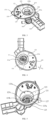
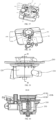
- the invention provides a filtering device 10 applied to a tableware washing apparatus.
- the filtering device 10 includes a water cup assembly 100, a plane filter 200 arranged on the water cup assembly 100, a rotary filter 300 at least partially inserted in the water cup assembly 100, and a drive assembly 400 connected to the rotary filter 300. Both the plane filter 200 and the rotary filter 300 are configured to filter to-be-filtered water after a washing process of the tableware washing apparatus.
- the rotary filter 300 includes a columnar filtering screen 330.
- the to-be-filtered water can either be filtered by the plane filter 200 and out of the water cup assembly 100, or enter the columnar filtering screen 330 through an opening on the plane filter 200, filtered by the columnar filtering screen 330, and out of the water cup assembly 100.
- the drive assembly 400 is configured to drive/cause the columnar filtering screen 330 to rotate at a relative speed of 100 to 1000 r/min relative to contents in the columnar filtering screen 330 (components received in an internal space enclosed by the columnar filtering screen 330), for separating at least a portion of residue on the columnar filtering screen from the columnar filtering screen 330.
- the drive assembly 400 may cause the columnar filtering screen 330 to rotate relative to the contents in the columnar filtering screen 330 at a relative speed of 150 to 700 r/min.
- the columnar filtering screen 330 rotating relative to the contents in the columnar filtering screen 330 herein means that the columnar filtering screen 330 rotates by itself driven by the drive assembly 400, or the contents in the columnar filtering screen 330 is rotatable driven by the drive assembly 400.
- the mesh spacing herein may refer to a spacing between each adjacent meshes.
- the mesh count of meshes of the columnar filtering screen 330 is about 50 to 70 mesh.
- the diameter of an external circle defined by each mesh of the columnar filtering screen 330 is about 0.2 to 0.5 mm, and the mesh spacing ranges from about 0.4 to 0.6 mm.
- the diameter of the external circle defined by the mesh of the columnar filtering screen 330 is about 0.2 to 0.4 mm.
- the diameter of the external circle defined by the mesh of the columnar filtering screen 330 may be 0.3 to 0.4 mm, and the mesh spacing may range from 0.6 to 1.0 mm.
- the filtering device 10 applied to the tableware washing apparatus is required to filter residues with a minimum particle size of about 0.3 mm.
- a combination of coarse filtration and fine filtration is usually adopted for filtering, for example, a mesh aperture of 0.8 mm may be applied for coarse filtration, followed by a mesh aperture of 0.3 mm for fine filtration to improve the filtering effect.
- a mesh aperture of 0.8 mm may be applied for coarse filtration, followed by a mesh aperture of 0.3 mm for fine filtration to improve the filtering effect.
- the problem of mesh clogging still easily occurs, which causes a poor filtering effect.
- the plane filter 200 and the rotary filter 300 are adopted to filter the to-be-filtered water, and at least a portion of the rotary filter 300 is driven by the drive assembly 400 to rotate the columnar filtering screen 330 relative to the contents inside the columnar filtering screen 330 at a relative speed of 100 to 1000 r/min.
- the diameter of the external circle defined by the mesh of the columnar filtering screen 330 (hereinafter referred to as the "mesh aperture”) is about 0.2 to 0 5 mm
- the mesh aperture of the filtering screen is usually designed to be small. However, if the mesh aperture is too small, it is difficult to form an aggregation of the residue and the residue tends to block the mesh, causing trapped air. In addition, if the rotation speed of the filtering screen is too small when rotating the contents inside the columnar filtering screen 330 relative to the columnar filtering screen 330, water flow may be subjected to resistance, causing clogging.
- the columnar filtering screen 330 is configured to rotate at a relative speed of 100 to 1000 r/min relative to the contents in the columnar filtering screen 330, and the mesh aperture diameter of the columnar filtering screen 330 is set to about 0.2 ⁇ 0.5mm, such that while increasing the filtration area and improving the filtering speed, the residue can be gathered at the bottom of the columnar filtering screen 330, reducing the possibility of the residue collecting on the filtering screen in the direction of the to-be-filtered water flow and blocking the flow of water, and also reducing the possibility of the residue leaking out of the filtering screen due to the excessive rotation speed of the filtering screen, thereby improving the filtering performance and filtering effect of the filtering device 10.
- a filtering effect of about 100% filtration may even be achieved when the diameter of the external circle defined by the mesh of the columnar filtering screen 330 is 0.3 mm and the columnar filtering screen 330 is rotated relative to the contents inside the columnar filtering screen 330 at a relative speed of 250 r/min.
- a first opening 250a is defined on the plane filter 200, and the columnar filtering screen 330 of the rotary filter 300 is disposed below the first opening 250a.
- a second opening 110a is defined on the water cup assembly 100 facing and communicated with the first opening 250a, and a projection of an inner wall enclosing the first opening 250a on the water cup assembly 100 is located in the second opening 110a, thereby defining a return chamber 123a between the water cup assembly 100 and the columnar filtering screen 330 of the rotary filter 300.
- the to-be-filtered water after the washing process can be filtered through the plane filter 200 and fall directly into the return chamber 123a; also, can fall through the first opening 250a into the rotary filter 300 and be filtered through the columnar filtering screen 330 of the rotary filter 300, and thereafter enter the return chamber 123a.
- the filtered water entering the return chamber 123a can be subsequently discharged through an outlet pipe 150 of the water cup assembly 100.
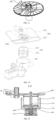
- the water cup assembly 100 may include a tray 110, a cup 120 connected to the tray 110, a spray arm interface 130 arranged on the tray 110, and a drive accommodating portion 140, an outlet pipe 150, a discharge pump accommodating portion 160, and a water-extraction pump accommodating portion 170, each connected to the cup 120.
- the plane filter 200 is arranged on the tray 110, and the tray 110 is configured to collect the water filtered by the plane filter 200.
- the cup 120 is configured to accommodate the columnar filtering screen 330, and the drive accommodating portion 140 is configured to accommodate at least the motor 410 of the drive assembly (referring to FIG. 32 ).
- the outlet pipe 150 is communicated with the cup 120 such that the filtered water can be discharged through the outlet pipe 150.
- the discharge pump accommodating portion 160 is communicated with the cup 120 and is configured to accommodate a discharge pump (not shown) to discharge the residue from the cup 120 by the pumping action of the discharge pump.
- the water-extraction pump accommodating portion 170 is configured to accommodate a water-extraction pump (not shown).
- the water-extraction pump accommodating portion 170 is connected to the outlet pipe 150 through a line to transport the to-be-filtered water in the cup 120 to the outside of the cup 120, specifically to the spray arm interface 130 on the tray 110, after being filtered by the columnar filtering screen 330, by the pumping action of the water-extraction pump.
- the outlet pipe 150, the water-extraction pump accommodating portion 170, and the discharge pump accommodating portion 160 are spaced along a circumference of the cup 120.
- the water-extraction pump accommodating portion 170 is arranged adjacent to the outlet pipe 150 to reduce the loss of water flow.
- the discharge pump accommodating portion 160 is arranged on a side of the water-extraction pump accommodating portion 170 away from the outlet pipe 150 and is disposed at a junction position between the drive accommodating portion 140 and the cup 120, thereby reducing mutual interference between the residue discharge process and the water discharge process, and saving the installation space of each component.
- the "junction position" herein means that the discharge pump accommodating portion 160 is disposed at a corner position formed by the intersection of the drive accommodating portion 140 and the cup 120.
- the cup 120 may include a top surface and a bottom surface disposed opposite each other along an axial direction of the cup 120.
- the drive accommodating portion 140 does not protrude from a bottom surface of the cup 120 along the axial direction of the cup 120.
- the drive accommodating portion 140 may not protrude from the top surface of the cup 120 along the axial direction of the cup 120.
- the drive accommodating portion 140 may neither protrude from the top surface of the cup 120 nor protrude from the top surface of the cup 120 along the axial direction of the cup 120.
- the drive accommodating portion 140 may likewise include a top surface and a bottom surface disposed opposite each other along the axial direction of the cup 120.
- the top surface of the drive accommodating portion 140 is disposed between the top surface and the bottom surface of the cup 120 in the height direction, or a bottom surface of the drive accommodating portion 140 is disposed between the top surface and the bottom surface of the cup 120 in the height direction, or the top surface of the drive accommodating portion 140 is flush with the top surface of the cup 120 in the height direction, or the bottom surface of the drive accommodating portion 140 is flush with the bottom surface of the cup 120 in the height direction.
- the drive accommodating portion 140 does not protrude from the bottom surface of the cup 120 along the axial direction of the cup 120, such that a motor may be added without changing the original height of the filtering device 10, and the space along the height direction of the filtering device 10 may be saved, making the entire filtering device 10 more compact.
- bottom surface herein refers to an outer surface of the cup 120 away from the tray 110.
- the drive accommodating portion 140 may protrude at least partially from the bottom surface of the cup 120 along the axial direction of the cup 120.
- the ratio of the protruding height of the bottom surface of the drive accommodating portion 140 to the height of the motor is less than 1:1.
- the drive accommodating portion 140 protrudes at least partially from the bottom surface of the cup 120 and the ratio of the protruding height to the height of the motor is less than 1:1, which may save space along the height direction of the filtering device 10 and makes the entire filtering device 10 more compact.
- the ratio of the protruding height of the bottom surface of the drive accommodating portion 140 relative to the bottom surface of the cup 120 to the height of the motor is less than 1:5 or even less than 1:7. In some embodiments, the ratio of the protruding height of the bottom surface of the drive accommodating portion 140 relative to the bottom surface of the cup 120 to the height of the motor is 1:16 to 1:5, and in other embodiments the ratio may be 1: 12 to 1:7.
- the height of the motor may be 50 to 80 mm, or in some embodiments the height of the motor may be 70 mm. Accordingly, the protruding height of the drive accommodating portion 140 relative to the bottom surface of the cup 120 may be 5 to 10 mm.
- the protruding height of the drive accommodating portion 140 relative to the bottom surface of the cup 120 may be 5 mm. Taking the above range, such as less than 1:5 or 1:7, etc., the protrusion height of the drive accommodating portion 140 and the motor arranged in the drive accommodating portion 140 may be further reduced, thereby further saving space along the height direction of the filtering device 10 and making the entire filtering device 10 more compact.
- the "protruding height” herein refers to a distance between the bottom surface of the drive accommodating portion 140 and the bottom surface of the cup 120.
- the tray 110 defines the second opening 110a, and the water collected by the tray 110 after being filtered by the plane filter 200 can fall through the second opening 110a to the bottom of the tray 110.
- the spray arm interface 130 is arranged on the tray 110, and the spray arm interface 130 and the second opening 110a are disposed at intervals along a first direction X.
- the tray 110 may be substantially elliptical in shape and have a long axis 111 and a short axis 112 that intersect with each other, where the long axis 111 may be set along the first direction X, i.e., the first direction X is the direction in which the long axis 111 of the tray 110 is located.
- the short axis 112 may be set in a second direction Y perpendicular to the first direction X, i.e., the second direction Y is the direction in which the short axis 112 of the tray 110 is located.
- the ratio of the length of the long axis 111 and the short axis 112 may be 5:3, which may facilitate the arrangement of the spray arm interface 130 and increase the water-passing area when filtering, such that most of the to-be-filtered water after washing can fall into the rotary filter 300 through the first opening 250a on the plane filter 200, and enter the return chamber 123a after being filtered by the columnar filtering screen 330, or enter directly into the return chamber 123a filtered by the plane filter 200.
- the tray 110 is elliptical.
- the tray 110 may be configured in other shapes, such as round, square, rectangular, diamond-shaped, etc., as long as the tray 110 has enough space to arrange the spray arm interface 130 and define the second opening 110a and can carry the plane filter 200.
- the cup 120 is substantially columnar in shape.
- the columnar filtering screen 330 of the rotary filter 300 may be accommodated in the cup 120, and a gap exists between an inner surface of the cup 120 and an outer surface of the columnar filtering screen 330.
- the ratio of an inner diameter of the cup 120 to an inner diameter of the columnar filtering screen 330 is about 3:4 to 8:9, and the width of the gap between the inner surface of the cup 120 and the outer surface of the columnar filtering screen 330 along a radial direction of the cup 120 is about 10 to 20 mm.
- the height of the cup 120 is about 90 to 110 mm
- the inner diameter of the cup 120 is about 80 to 100 mm
- the inner diameter of the columnar filtering screen 330 is about 60 to 80mm. This size design may effectively reduce the problem of air extraction during the water return process, ensure the smooth flow of water such that the water can fill the return chamber 123a, and reduce the possibility of air adulteration in the return chamber 123a, thereby ensuring the flow of the washing process and improving the filtration performance.
- the cup 120 may substantially include a bottom wall 121 and a first peripheral wall 123 and a second peripheral wall 125 that are connected to the bottom wall 121.
- the first peripheral wall 123 and the second peripheral wall 125 are connected to opposite sides of the bottom wall 121, respectively. That is, the first peripheral wall 123 is connected to a side of the bottom wall 121, and the second peripheral wall 125 is connected to the other side of the bottom wall 121 opposite to the side of the bottom wall 121. That is, the first peripheral wall 123 extends toward a side of the bottom wall 121, and the second bottom wall 125 extends toward the other side of the bottom wall 121.
- the first peripheral wall 123 encloses a receiving cavity (not shown) for receiving the columnar filtering screen 330.
- the columnar filtering screen 330 may be received in the receiving cavity, and the columnar filtering screen 330 may divide the receiving cavity into a filtration chamber for receiving the to-be-filtered water inside the columnar filtering screen 330 and the return chamber 123a disposed outside the columnar filtering screen 330.
- the first peripheral wall 123 further defines a first water outlet 123b, and the outlet pipe 150 is connected to the return chamber 123a through the first water outlet 123b.
- the second bottom wall 125 may enclose a discharge cavity 125a, and the second bottom wall 125 may further define a discharge outlet 125b.
- the discharge pump accommodating portion 160 is communicated with the discharge cavity 125a through the discharge outlet 125b.
- the bottom wall 121 may further define a through hole 121a, and the receiving cavity and the discharge cavity 125a are communicated with each other through the through hole 121a.
- first peripheral wall 123 and the second peripheral wall 125 may each be an annular peripheral wall.
- first peripheral wall 123 and the second peripheral wall 125 may also be other shapes.
- the first peripheral wall 123 and the second peripheral wall 125 may be integrally formed into one part, or separately formed, which is not limited herein.
- the cup 120 may further include a support tab 127, which is connected to the bottom wall 121 and extends from the bottom wall 121 toward the receiving cavity.
- the support tab 127 is arranged around the through hole 121a.
- the inner surface of the columnar filtering screen 330 may be abutted against an outer surface of the support tab 127, to support the columnar filtering screen 330 on the support tab 127.
- the support tab 127 may be configured to support the columnar filtering screen 330 and may serve as a retaining wall to prevent the residue falling into the discharge cavity 125a from adhering to the columnar filtering screen 330 again by the action of flowing water.
- the "supported on” herein may be understood to mean that the support tab 127 only serves as a support, not as a fixing part. Therefore, the columnar filtering screen 330 may be fixed to the support tab 127 or not be fixed. For example, the columnar filtering screen 330 may be rotated relative to the support tab 127.
- the water seeps out of the columnar filtering screen 330 into the return chamber 123a and is delivered to the outside of the cup 120 through the first water outlet 123b.
- the residue falls into the discharge cavity 125a and is discharged through the pumping action of a discharge pump to the outside of the cup 120 through the discharge outlet 125b.
- the discharge outlet 125b is defined at the bottom of the cup 120. In some embodiments, the discharge outlet 125b is defined at a lowest position at the bottom of the cup 120 to facilitate the collection and discharge of the residue.
- an angle ⁇ between a line connecting the center of the discharge outlet 125b and the center of the cup 120 and a line connecting the center of the first water outlet 123b and the center of the cup 120 is greater than 90 degrees and less than or equal to 180 degrees. In some embodiments, the angle may be 180 degrees, in which case the discharge pump accommodating portion 160 and the outlet pipe 150 are arranged along the radial direction of the cup 120 on opposite sides of the cup 120.
- At least one guiding element 125c may be arranged inside the discharge cavity 125a.
- the at least one guiding element 125c is arranged adjacent to the discharge outlet 125b for guiding the residue during the discharge of the residue from the cup 120.
- a recess 129 is defined on the bottom wall 121 toward the receiving cavity, and the recess 129 is arranged adjacent to and communicated with the first water outlet 123b.
- the recess 129 is further communicated with the return chamber 123a.
- the recess 129 may be disposed between the first peripheral wall 123 and the support tab 127.
- the recess 129 may extend along a circumference of the cup 120 for a length greater than the length of the first water outlet 123b along the circumference of the cup 120, thereby ensuring that filtered water can sink to the recess 129 and flow out of the cup 120 in a timely manner through the first water outlet 123b. In this way, the filtered water can fill the outlet region of the cup without air in the process of pumping water through the pump, which can effectively reduce the probability of trapped air in the pump.
- the recess 129 may include a first recess portion 129a and a second recess portion 129d that are from inside to outside sequentially arranged along the radial direction of the cup 120.
- the first recess portion 129a has a first bottom surface 129b and the second recess portion 129d has a second bottom surface 129e.
- a recessed depth of the second bottom surface 129e relative to the bottom wall 121 is greater than a recessed depth of the first bottom surface 129b relative to the bottom wall 121.
- the "recessed depth” herein means a vertical distance (i.e., the distance along the axial direction of the cup 120) between the bottom surface (i.e., the first bottom surface 129b or the second bottom surface 129e) of the corresponding recess portion (first recess portion 129a or second recess portion 129d) and the bottom wall 121.
- the difference between the recessed depth of the first recess portion 129a and the recessed depth of the second recess portion 129d is about 5 to 8 mm.
- the design of two levels of recess portions to form the recess 129 may facilitate the injection molding process of the cup 120 and reduce the possibility of shrinkage and deformation of the recess 129 during the injection molding process of the cup 120.
- the recessed depth of the second bottom surface 129e relative to the bottom wall 121 may be further less than a recessed depth of a lowest point of an inner wall of the outlet pipe 150 at the first water outlet 123b relative to the bottom wall 121, thereby reducing the probability of trapped air during subsequent pumping, such that the water can adequately fill the outlet region of the cup 120 without mixing with air, ensuring the water flow of the washing process.
- the first recess portion 129a has an inclined surface 129c connecting the bottom wall 121 and the first bottom surface 129b. In some embodiments, an angle between the inclined surface 129c and the first bottom surface 129b is about 158.9° to 162.7°.
- the first recess portion 129a is set with an inclined surface, which allows the filtered water to smoothly transitioned into the recess 129 through the inclined surface 129c and flow into the outlet pipe 150 through the first water outlet 123b and then out of the cup 120.
- an end of the outlet pipe 150 is connected to the cup 120 and communicated with the return chamber 123a through the first water outlet 123b.
- the other end of the outlet pipe 150 is arranged with a second water outlet 151, and the outlet pipe 150 defines an outlet channel 150a between the first water outlet 123b and the second water outlet 151.
- the cross-sectional area of the outlet channel 150a decreases in a direction from the first water outlet 123b to the second water outlet 151, in conjunction with FIGS. 7 and 12 .
- the design of this structure of the outlet pipe 150 may effectively solve the problem of pumping air at the outlet location caused by the pump during the pumping process, such that the water adequately fills the outlet region without mixing with air, ensuring the flow of water during the washing process.
- the ratio of the cross-sectional area of the outlet channel 150a at the first water outlet 123b to the cross-sectional area of the outlet channel 150a at the second water outlet 151 is about 1.63 to 1.99.
- the ratio setting may more effectively solve the problem of pumping air at the outlet location caused by the pump during the pumping process, thereby improving the flow rate during the washing process.
- the cross-sectional area is the area of the cross-section dissected parallel to the axial direction of the columnar filtering screen 330.
- the cross-section of the outlet channel 150a at the first water outlet 123b is substantially elliptical in shape and the ratio of the lengths of the long and short axes of the elliptical is substantially 5:3.
- the elliptical design allows more filtered water to enter the outlet tube 150 at the same time as the water is being discharged, ensuring that the water fills the outlet region sufficiently without air admixture.
- the cross-section of the outlet channel 150a at the first water outlet 123b may also be round, square, etc.
- the diameter of the circular cross-section is about 35 mm, i.e., the inner diameter of the outlet pipe 150 at that first water outlet 123b is about 35 mm.
- the outlet channel 150a has a substantially circular cross-section at the second water outlet 151.
- the diameter of the circular cross-section of the outlet channel 150a at the second water outlet 151 is about 26 mm.
- the circular cross-section of the outlet channel 150a at the second water outlet 151 facilitates connection to external pipeline and thus to the pump.
- the shape of the cross-section of the outlet channel 150a at the first water outlet 123b and the second water outlet 151 and the size of the inner diameter of the outlet pipe 150 at the first water outlet 123b and the second water outlet 151 may be selected according to actual needs.
- the present disclosure is not limited herein specifically.
- the outlet pipe 150 includes a diameter-inconsistent portion 153 and a diameter-consistent portion 155 connected from the inside to the outside in the radial direction of the cup 120, and the diameter-inconsistent portion 153 and the diameter-consistent portion 155 are communicated with each other.
- the diameter-inconsistent portion 153 and the diameter-consistent portion 155 it may be ensured that the water adequately fills the outlet region without mixing air, and the connection with the external pipeline may be facilitated.
- the length of the diameter-consistent portion 155 may be greater than or equal to 15 mm. In other embodiments, the length of the diameter-consistent portion 155 may be greater than or equal to 20 mm.
- the diameter-inconsistent portion 153 is connected to the first peripheral wall 123 and defines a first sub outlet channel 153a connected to the return chamber 123a of the receiving cavity through the first water outlet 123b.
- the cross-sectional area of the first sub outlet channel 153a gradually decreases in the direction from the first water outlet 123b to the second water outlet 151.
- the diameter-consistent portion 155 is arranged on a side of the outlet pipe 150 away from the return chamber 123a of the receiving cavity and defines a second sub outlet channel 155a communicated with the first sub outlet channel 153a, and the second water outlet 151 is arranged on the diameter-consistent portion 155.
- the first sub outlet channel 153a and the second sub outlet channel 155a form the aforementioned outlet channel 150a, and the cross-sectional area of the second sub outlet channel 155a remains constant along the direction from the first water outlet 123b toward the second water outlet 151.
- the diameter-inconsistent portion 153 has a first side 153b and a second side 153c in a cross-section perpendicular to the axial direction of the cup 120 and over the geometric center of the first water outlet 123b.
- the first side 153b is near the water-extraction pump accommodating portion 170 and the second side 153c is away from the water-extraction pump accommodating portion 170.
- the diameter-inconsistent portion 153 has a cross-sectional area between the first side 153b and the first peripheral wall 123.
- the diameter-inconsistent portion 153 forms a first intersection 153d at the connection of the first side 153b with the first peripheral wall 123 and a second intersection 153e at the connection with the diameter-consistent portion 155, while the diameter-inconsistent portion 153 forms a third intersection 153f at the connection of the second side 153c with the first peripheral wall 123 and a fourth intersection 153g at the connection with the diameter-consistent portion 155.
- the length of a line between the first intersection 153d and the second intersection 153e is less than the length of a line between the third intersection 153f and the fourth intersection 153g, and the angle between the line between the first intersection 153d and the second intersection 153e and a tangent line of the first peripheral wall 123 at the first intersection 153d is greater than the angle between the line between the third intersection 153f and the fourth intersection 153g and a tangent line of the first peripheral wall 123 at the third intersection 153f.
- the angle between the diameter-inconsistent portion 153 on the first side 153b and the diameter-consistent portion 155 may be less than the angle between the diameter-inconsistent portion 153 on the second side 153c and the diameter-consistent portion 155.
- the diameter-inconsistent portion section 153 may be arranged symmetrically about the centerline of the outlet pipe 150. That is, the length of the line between the first intersection 153d and the second intersection 153e is equal to the length of the line between the third intersection 153f and the fourth intersection 153g, and the angle between the line between the first intersection 153d and the second intersection 153e and the tangent line of the first peripheral wall 123 at the first intersection 153d is equal to the angle between the line between the third intersection 153f and the fourth intersection 153g and the tangent line of the first peripheral wall 123 at the third intersection 153f.
- the present disclosure is not specifically limited herein.
- a side of the outlet pipe 150 away from the water-extraction pump accommodating portion 170 may be tangential to an outer peripheral wall of the cup 120 (specifically, the outer surface of the first peripheral wall 123), such that filtered water may enter the outlet pipe 150 more smoothly, thereby reducing the resistance to the water generated by the outlet pipe 150.
- the height of the outlet channel 150a along the axis of the columnar filtering screen 330 remains constant in the direction from the first water outlet 123b to the second water outlet 151, thereby reducing the installation height along the axis of the columnar filtering screen 330 and saving space in that direction, resulting in a lower installation height and more compact structure of the entire filtering device 10.
- the filtering device 10 further includes a spray arm adapter 500 arranged on the plane filter 200, which is connected to and communicated with the spray arm interface 130 on the tray 110, for spraying the filtered water of the filtering device 10 into the inner liner of the tableware washing apparatus through the spray arm adapter 500.
- a spray arm adapter 500 arranged on the plane filter 200, which is connected to and communicated with the spray arm interface 130 on the tray 110, for spraying the filtered water of the filtering device 10 into the inner liner of the tableware washing apparatus through the spray arm adapter 500.
- the plane filter 200 may include a face-shaped screen holder 250, and a first face-shaped screen 210 and a second face-shaped screen 230 arranged side by side in the first direction X.
- the first opening 250a is defined on the face-shaped screen holder 250.
- the columnar filtering screen 330 is disposed below the face-shaped screen holder 250 and facing the first opening 250a. Therefore, the to-be-filtered water can fall from the first opening 250a into the columnar filtering screen 330 below the face-shaped screen holder 250.
- the spray arm adapter 500 is arranged on the face-shaped screen holder 250 and is spaced apart from the first opening 250a along the first direction X.
- first face-shaped screen 210 and the second face-shaped screen 230 may both be plane screens. In other embodiments, the first face-shaped screen 210 and the second face-shaped screen 230 may be curved screens with curves, or one of the first face-shaped screen 210 and the second face-shaped screen 230 may be a plane screen and the other a curved screen. The present disclosure does not limit the shape of the first face-shaped screen 210 and the second face-shaped screen 230.
- the second face-shaped screen 230 is away from the spray arm adapter 500 along the first direction X compared to the first face-shaped screen 210.
- the area of the first face-shaped screen 210 is greater than the area of the second face-shaped screen 230.
- a first angle ⁇ 1 may be formed between the first face-shaped screen 210 and a reference plane perpendicular to the axial direction of the first opening 250a, and a second angle ⁇ 2 may be formed between the second face-shaped screen 230 and the reference plane, the first angle ⁇ 1 being less than the second angle ⁇ 2.
- first face-shaped screen 210 and the second face-shaped screen 230 are separate structures, i.e., the first face-shaped screen 210 and the second face-shaped screen 230 are separately machined and stitched together.
- first face-shaped screen 210 and the second face-shaped screen 230 may each be of a one-piece structure; for example, the first face-shaped screen 210 and the second face-shaped screen 230 may be formed by bending the entire screen at a predetermined location.
- the present disclosure does not limit the way of forming and combining the first face-shaped screen 210 and the second face-shaped screen 230.
- the plane filter 200 is divided into a plurality of different face-shaped screens and spliced with each other through the face-shaped screen holder 250, which may increase the filtration area, improve the filtering speed, reduce the probability of empty pumping caused by untimely water return, and facilitate the manufacture of the plane filter 200.
- the distances between the first face-shaped screen and the second face-shaped screen at corresponding positions and the reference plane may be approximately equal, such that the to-be-filtered water falls more smoothly into the tray 110 through the different positions of the plane filter 200 or into the columnar filtering screen 330 through the first opening 250a.
- the ratio of the first angle ⁇ 1 to the second angle ⁇ 2 may be 1:5 to 1:2. In some embodiments, the ratio of the first angle ⁇ 1 to the second angle ⁇ 2 is about 1:3.
- the first angle ⁇ 1 and the second angle ⁇ 2 are set such that a distance from an outer edge of the first face-shaped screen 210 away from the second face-shaped screen 230 along the first direction X and/or the second direction Y perpendicular to the first direction X to the reference plane along the axial direction of the first opening 250a is the same as a distance from an outer edge of the second face-shaped screen 230 away from the first face-shaped screen 210 along the first direction X and/or the second direction Y to the reference plane along the axial direction of the first opening 250a, thereby allowing the to-be-filtered water to fall more smoothly into the tray 110 through the different positions of the plane filter 200 or into the columnar filtering screen 330 through the first opening 250a.
- the opposing outer edges of the first face-shaped screen 210 and the second face-shaped screen 230 along the first direction X may be set at equal distances from the reference plane along the axial direction of the first opening 250a.
- the first face-shaped screen 210 has a first outer edge 211 in the first direction, a projection of which in the reference plane is at a maximum distance h1 from the center of the first opening 250a, and a first angle ⁇ 1 exists between the first face-shaped screen 210 and the reference plane.
- the second face-shaped screen 230 has a second outer edge 231 in the first direction, and the second outer edge 231 and the first outer edge 211 are disposed on opposite sides of the first opening 250a, respectively.
- the opposing outer edges of the first face-shaped screen 210 and the second face-shaped screen 230 along the second direction Y may be set at equal distances from the reference plane along the axial direction of the first opening 250a.
- the entire plane filter 200 is arranged symmetrically about the first direction X.
- the first face-shaped screen 210 has two opposing third outer edges 213 in the second direction Y, and the two third outer edges 213 are equidistant from the reference plane along the axial direction of the first opening 250a.
- the second face-shaped screen 230 has two opposing fourth outer edges 233 in the second direction Y, and the two fourth outer edges 233 are equidistant from the reference plane along the axial direction of the first opening 250a.
- the first angle ⁇ 1 and the second angle ⁇ 2 are set such that the opposing outer edges of the first face-shaped screen 210 and the second face-shaped screen 230 along the first direction X are at equal distances from the reference plane along the axial direction of the first opening 250a, and the opposing outer edges of the first face-shaped screen 210 and the second face-shaped screen 230 along the second direction Y are at equal distances from the reference plane along the axial direction of the first opening 250a.
- a dividing line 220 of the first face-shaped screen 210 and the second face-shaped screen 230 is disposed on a side of the center of the first opening 250a away from the spray arm adapter 500 and intersecting with the first opening 250a.
- the dividing line 220 is off-center from the center of the first opening 250a. The eccentric arrangement of the dividing line 220 facilitates the arrangement of the spray arm adapter 500 while allowing the water to fall smoothly into the columnar filtering screen 330.
- the number of first face-shaped screens 210 and the number of second face-shaped screens 230 are each two.
- the two first face-shaped screens 210 are arranged side by side in the second direction perpendicular to the first direction X
- the two second face-shaped screens 230 are arranged side by side in the second direction perpendicular to the first direction X.
- the dividing line between one first face-shaped screen 210 and one second face-shaped screen 230 and the dividing line between the other first face-shaped screen 210 and the other second face-shaped screen 230 are symmetrically arranged about a line connecting the center of the first opening 250a and the center of the spray arm adapter 500.
- the two first plane screens 210 are arranged symmetrically about the line connecting the center of the first opening 250a and the center of the spray arm adaptor, and the two second plane screens 230 are arranged symmetrically about the line connecting the center of the first opening 250a and the center of the spray arm adaptor.
- the mesh count of meshes of each of the first face-shaped screen 210 and the second face-shaped screen 230 is about 50 to 70 mesh.
- the diameter of an external circle defined by each mesh of each of the first face-shaped screen 210 and the second face-shaped screen 230 is about 0.2 to 0.5 mm, and the mesh spacing ranges from about 0.4 to 0.6 mm.
- the diameter of the external circle defined by each mesh of each of the first face-shaped screen 210 and the second face-shaped screen 230 is about 0.2 to 0.4 mm.
- the diameter of the external circle defined by each mesh of each of the first face-shaped screen 210 and the second face-shaped screen 230 may be 0.3 to 0.4 mm, and the mesh spacing ranges from 0.6 to 1.0 mm.
- the face-shaped screen holder 250 may include an outer frame 251, an inner frame 253 embedded within the outer frame 251 and facing the first opening 250a, and at least one support rib 255 connected between the outer frame 251 and the inner frame 253.
- the outer frame 251 and the inner frame 253 enclose a receiving region for the first face-shaped screen 210 and the second face-shaped screen 230, and the at least one support rib 255 divides the receiving region into regions for receiving the first face-shaped screen 210 and the second face-shaped screen 230.
- Edges of the first face-shaped screen 210 and the second face-shaped screen 230 abut against the outer frame 251, the inner frame 253, and the at least one support rib 255, respectively, such that the first face-shaped screen 210 and the second face-shaped screen 230 are supported on the face-shaped screen holder 250.
- the number of first face-shaped screens 210 and the number of second face-shaped screens 230 are each two, and the number of support ribs 255 is four.
- the inner frame 253 is generally circular in shape and the four support ribs 255 are arranged around a circumference of the inner frame 253, thereby dividing the receiving region into four regions (corresponding to the two first face-shaped screens 210 and two second face-shaped screens 230), such that the first face-shaped screens 210 and the second face-shaped screens 230 are firmly supported on the face-shaped screen holder 250.
- the support ribs 255 are adopted to divide the receiving region to facilitate the processing and shaping of the filtering screens.
- the face-shaped screen holder 250 may further include a support platform 257 connected between the outer frame 251 and the inner frame 253 and arranged adjacent to the first face-shaped screen 210.
- the spray arm adapter 500 is arranged on the support platform 257.
- the rotary filter 300 may include a columnar screen holder 310 and the columnar filtering screen 330.
- the columnar screen holder 310 is inserted within the cup 120.
- the columnar filtering screen 330 is supported on the columnar screen holder 310 and is arranged facing the first opening 250a for filtering the to-be-filtered water.
- the columnar filtering screen 330 is rotatable relative to the contents of the columnar filtering screen 330.
- the columnar screen holder 310 may be integrally molded with the inner frame 253, which may make the whole filtering device better integrated and sealed, and may reduce the possibility of residue leaking out to the return chamber 123a through the seams or fits of the inner frame 253 and the columnar screen holder 310.
- the columnar screen holder 310 may be separated from the inner frame 253 and may be rotatably connected to the inner frame 253, thereby facilitating the rotation of the columnar screen holder 310 and the columnar filtering screen 330 supported thereon relative to the plane filter 200.
- the contents of the columnar filtering screen 330 are rotatable by the drive assembly 400, thereby allowing the columnar filtering screen 330 to rotate relative to the contents.
- the rotary filter 300 includes the columnar filtering screen 330, the columnar screen holder 310, and a cleaning element 350, where the specific design of the columnar screen holder 310 and the columnar filtering screen 330 is as previously described and will not be repeated herein.
- the columnar screen holder 310 may be integrally formed with the inner frame 253.
- the cleaning element 350 is accommodated within the columnar filtering screen 330 and is in contact with, or abutting against, an inner wall (or inner surface) of the columnar filtering screen 330. In some embodiments, a bottom of the cleaning element 350 may further be in contact with and supported on the support tab 127. Of course, in other embodiments, the cleaning element 350 may not be in contact with the support tab 127.
- the drive assembly 400 may be connected to the cleaning element 350 to drive the cleaning element 350 to rotate for separating at least a portion of the residue from the columnar filtering screen 330 by the cleaning element 350.
- the drive assembly 400 may drive the cleaning element 350 to rotate relative to the columnar filtering screen 330 at a speed of about 150 to 400 r/min. Using the cleaning element 350 to rotate at this speed reduces the probability of failure to form a residue collection caused by residue being thrown out of the columnar filtering screen 330 due to excessive rotation speed, and also reduces the probability that resistance to the flow of to-be-filtered water will be formed due to too little rotation speed. Referring to FIG.
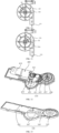
- the cleaning element 350 may include a mounting bracket 351 and a contact portion 353 arranged on the mounting bracket 351.
- the mounting bracket 351 may be connected to the drive assembly 400 and rotatable under the drive of the drive assembly 400, thereby driving the entire cleaning element 350 to rotate.
- the mounting bracket 351 may include a connection portion 3511 and a shelf portion 3513.
- the connection portion 3511 is coaxially disposed with a motor of the drive assembly 400 and is rotatable under the drive of the motor.
- a side of the shelf portion 3513 is connected to the connection portion 3511, and the contact portion 353 may be arranged on another side of the shelf portion 3513 away from the connection portion 3511.
- the number of contact portions 353 is the same as the number of shelf portions 3513, or to say, the contact portions 353 are in one-to-one correspondence with the shelf portions 3513.
- the shelf portion 3513 may be integrally formed with the connection portion 3511.
- the shelf portion 3513 may be molded separately from the connection portion 3511.
- the shape of the shelf portion 3513 is not limited to the frame structure with a hollow portion shown in the drawings, and in some embodiments, the shelf portion 3513 may be a solid (not hollow) structure.
- the cleaning element 350 may include at least two shelf portions 3513, and each shelf portion 3513 is arranged with a contact portion 353.
- the number of contact portions 353 is also two, and the two shelf portions 3513 may be arranged symmetrically about an axial direction of the connection portion 3511, as shown in FIGS. 19-20 .
- three or more shelf portions 3513 and three or more contact portions 353 may be arranged.
- the number of the shelf portions 3513 and the number of the contact portions 353 are each three, and the three shelf portions 3513 are evenly distributed at equal distances along the circumference of the connection portion 3511.
- the number of the shelf portion 3513 and the number of the contact portion 353 are each one. The present disclosure does not limit the number, material, and size of such shelf portion 3513 and contact portion 353.
- the contact portion 353 may be a scraper, and the contact portion 353 may be made of, for example, silicone, rubber, and other materials.
- the contact portion 353 has a height of about 40 to 60 mm and a width of about 0.9 to 1.1 mm.
- the contact portion 353 may generate a torque of about 0.4 to 0.6 N*m to cause as much residue as possible to fall off or be separated from the columnar filtering screen 330.
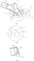
- the rotary filter 300 may include the columnar screen holder 310, the columnar filtering screen 330, and a wave wheel 370.
- the specific design of the columnar screen holder 310 and the columnar filtering screen 330 is as previously described and will not be repeated herein.
- the columnar screen holder 310 may be integrally formed with the inner frame 253.
- the wave wheel 370 is rotatably accommodated in the columnar filtering screen 330 and is disposed at a bottom of the columnar filtering screen 330, i.e., on a side away from the plane filter 200.
- the drive assembly 400 is connected to the wave wheel 370 to drive the wave wheel 370 to rotate relative to the columnar filtering screen 330 at a speed of about 500 to 700 r/min for stirring the to-be-filtered water within the columnar filtering screen 330, such that at least a portion of the residue cannot adhere to the columnar filtering screen 330, thereby allowing at least a portion of the residue to be separated from the columnar filtering screen 330 and facilitating water penetration through the mesh of the columnar filtering screen 330 to the return chamber 123a to achieve effective filtration.
- the use of the wave wheel 370 rotating at this speed reduces probability of failure to form a residue collection caused by residue being thrown out of the columnar filtering screen 330 due to excessive rotation speed, and also reduces the probability that resistance to the flow of to-be-filtered water will be formed due to too little rotation speed.
- the wave wheel 370 may have three blades, as shown in FIG. 23 .
- the wave wheel 370 may include five or more blades.
- the present disclosure does not limit the number of blades of the wave wheel 370 herein.
- the shape of the wave wheel 370 is not limited to the shape shown in FIG. 23 , and may take any suitable shape, as long as the wave wheel can stir the to-be-filtered water in the columnar filtering screen 330.
- the contents of the columnar filtering screen 330 e.g., the cleaning element 350 and the wave wheel 370
- the contents of the columnar filtering screen 330 can be rotated relative to the columnar filtering screen 330 such that at least a portion of the residue can be separated from the columnar filtering screen 330.
- a portion of the columnar filtering screen 330 adjacent to the first water outlet 123b can be changed such that the residue can be dispersed to different positions of the columnar filtering screen 330, thereby effectively reducing the possibility of local blockage caused by the residue collecting at a certain position of the columnar filtering screen 330, facilitating the stripping and cleaning of at least a portion of the residue from the columnar filtering screen 330, and improving the filtration performance of the filtering device 10 and improving the overall tableware washing apparatus.
- the rotary filter 300 may include a columnar screen holder 310 and a columnar filtering screen 330, and the columnar filtering screen 330 is supported on the columnar screen holder 310.
- the drive assembly 400 is connected to the columnar screen holder 310 and drives the columnar screen holder 310 to rotate, and the columnar screen holder 310 drives the columnar filtering screen 330 to rotate relative to the to-be-filtered water in the columnar filtering screen 330, such that at least a portion of the residue can be separated from the columnar filtering screen 330 by the rotation of the columnar filtering screen 330.
- the rotation speed of the columnar filtering screen 330 is about 500 to 700 r/min.
- the height of the cup 120 is about 90 to 110 mm
- the inner diameter of the cup 120 is about 80 to 100 mm
- the inner diameter of the columnar filtering screen 330 is about 60 to 80 mm.
- Driving the columnar filtering screen 330 to rotate at this speed, while matching the inner diameter of the cup 120 and the inner diameter of the columnar filtering screen 330, may reduce the probability of failure to form a residue collection caused by residue being thrown out of the columnar filtering screen 330 due to excessive rotation speed, and also reduces the probability that resistance to the flow of to-be-filtered water will be formed due to too little rotation speed, thereby effectively reducing the problem of pumping air in the water return process, ensuring smooth water flow and filling the return chamber, reducing the possibility of the air being mixed in the return chamber 123a, thus ensuring the washing process flow, improving the filtration performance, and achieving better filtering effect.
- the outlet channel 150a may be of the cross-section-inconsistent design shown in FIG. 13 .
- the columnar screen holder 310 includes a main part 311, a positioning post 315, and at least one connecting rib 313 connecting the main part 311 and the positioning post 315.
- the main part 311 has a columnar frame structure and the columnar filtering screen 330 may be hung or supported on the main part 311.
- the positioning post 315 is disposed at a position substantially at a central axis of the main part 311 to be connected to an output shaft of the drive assembly 400 (e.g., the output shaft 438 of the second spur gear 437 shown in FIG. 25 ) and the inner frame 253 of the plane filter 200.
- the positioning post 315 may define an assembly hole 317 at an end connected to the drive assembly 400, and the output shaft of the drive assembly 400 may be inserted in the assembly hole 317, thereby driving the positioning post 315 to rotate the columnar screen holder 310, which in turn rotates the columnar filtering screen 330 arranged on the columnar screen holder 310.
- the number of the connecting ribs 313 is two or more.
- the columnar screen holder 310 includes three connecting ribs 313, and the three connecting ribs 313 may be evenly distributed around a circumference of the positioning post 315.
- FIGS. 28-31 illustrate a relative position of the residue in relation to the direction of water flow in the return chamber 123a at different moments when filtering with the rotatable columnar filtering screen 330.
- the filtered water flows out of the return chamber through the first outlet.
- the residue is disposed at a first position P1.
- the residue adheres to the inner surface of the columnar filtering screen 330 due to the suction force near the first water outlet 123b (suction force is generated by the pump).
- suction force is generated by the pump.
- the columnar filtering screen 330 is rotated at an angle driven by the drive assembly 400 such that the residue is disposed at a second position P2.
- the water disposed in the return chamber reacts to the residue on the columnar filtering screen 330 due to the suction force of the pump, such that the residue begins to separate from the columnar filtering screen 330.
- the columnar filtering screen 330 continues to rotate and at a third moment the residue reaches a third position P3 and is completely separated from the columnar filtering screen 330.
- a fourth moment as shown in FIG.
- the columnar filtering screen 330 is rotated to a predetermined position such that the residue is disposed in a fourth position P4, at which time the residue has been completely separated from the columnar filtering screen 330 without adhering to the inner surface of the columnar filtering screen 330, and the residue further approaches the axial direction of the columnar filtering screen 330 and can fall into the discharge cavity 125a.
- the portion of the columnar filtering screen 330 adjacent to the first water outlet 123b can be changed such that the residue can be dispersed to different positions of the columnar filtering screen 330, thereby effectively reducing the possibility of local blockage caused by the residue collecting at a certain position of the columnar filtering screen 330, facilitating the stripping and cleaning of at least a portion of the residue from the columnar filtering screen 330, thus allowing the water to smoothly penetrate into the return chamber 123a and flow into the outlet pipe 150.
- the filtration performance of the filtering device 10 and the overall stability of the tableware washing apparatus can be improved.
- the rotation of the columnar filtering screen 330 is driven by an external drive assembly 400.
- the present disclosure does not limit the driving force of the columnar filtering screen 330 herein.
- the drive assembly 400 may include a motor 410 and a reduction mechanism 430.
- the motor 410 is arranged horizontally, i.e., an output shaft 411 of the motor 410 is perpendicular to the axial direction of the cup 120, thereby saving space in the height direction and making the entire filtering device 10 more compact.
- the reduction mechanism 430 may be a reduction gear mechanism, which may include a first bevel gear 431, a second bevel gear 433, a first straight gear 435, and a second spur gear 437.
- the first bevel gear 431 and the first straight gear 435 are arranged coaxially.
- the second bevel gear 433 is connected to the output shaft 411 of the motor 410 and engages with the first bevel gear 431.
- the second spur gear 437 engages the first spur gear 435, and an output shaft 438 of the second spur gear 437 is inserted into the cup 120 from an outer surface (bottom surface) of the bottom of the cup 120 and is connected to a portion of the rotary filter 300 (e.g., the aforementioned columnar screen holder 310, cleaning element 350, or wave wheel 370), thereby driving the columnar filtering screen 330 to rotate relative to the contents.
- the reduction mechanism 430 may further include a cantilever assembly 439, and the cantilever assembly 439 is configured to hold down the first bevel gear 431 and the first spur gear 435.
- the motor 410 has a mounting height along the axial direction of the cup 120 of substantially about 80 to 100 mm, and the motor 410 may be accommodated within the drive accommodating portion 140. In some embodiments, the top of the motor 410 does not protrude from the top surface of the cup 120, and the bottom of the motor 410 does not protrude from the bottom surface of the cup 120.
- the bottom of the motor 410 may partially protrude from the bottom surface of the cup 120, as long as the ratio of the protruding height of the bottom surface of the drive accommodating portion 140 to the height of the motor is less than 1:1, thereby saving space along the height of the filtering device 10 and making the entire filtering device 10 more compact.
- the drive accommodating section 140 is arranged facing the reduction mechanism 430.
- the drive accommodating portion 140 may include a motor mounting part 141, a first fixing part 143, a second fixing part 145, and a third fixing part 147.
- the motor 410 may be arranged on the motor mounting part 141.
- the first fixing part 143 has a generally circular outer profile and is intersected with the motor mounting portion 141, for arranging the coaxially fixed first bevel gear 431 and the first spur gear 435.
- the second fixing part 145 has a generally circular outer profile and is intersected with the first fixing part 143.
- the second fixing part 145 is disposed below the cup 120 and is configured to arrange the second spur gear 437.
- the third fixing part 147 has a generally circular outer contour and is intersected with both the motor mounting portion 141 and the first fixing part 143, for arranging the cantilever assembly 439.
- the cantilever assembly 439 may extend from the third fixing part 147 to the first fixing part 143.
- an oil seal 600 may be arranged between the output shaft 438 of the second spur gear 437 and the cup 120. The oil seal 600 may ensure the rotation of the output shaft 438 and reduce the possibility of failure of the reduction mechanism 430 caused by water in the cup 120 seeping into the reduction mechanism 430.
- the reduction mechanism is implemented by a reduction gear mechanism.
- the reduction mechanism may be implemented using other reduction mechanisms, such as a belt drive mechanism.
- the drive assembly 400 may include a motor 410a, an active wheel 431a, a driven wheel 433a, and a belt 435a connecting the active wheel 431a and the driven wheel 433a.
- the motor 410a is accommodated in the drive accommodating portion 140, and an output shaft 411a of the motor 410a is arranged along the axial direction of the cup 120 and extends to the outside of the drive accommodating portion 140.
- the active wheel 431a is arranged on the outside of the drive accommodating portion 140 and is connected to the output shaft 411a of the motor 410a.
- the driven wheel 433a is arranged on the outside of the drive accommodating portion 140 and is in transmission connection with the main wheel 431a through the belt 435a.
- an output shaft 438a of the driven wheel 433a is inserted inside the cup 120 from the outer surface of the bottom of the cup 120 and is connected to a portion of the rotary filter 300 (e.g., the aforementioned columnar screen holder 310, the cleaning element 350, or the wave wheel 370), thereby driving the columnar filtering screen 330 to rotate relative to the contents.
- This type of reduction mechanism 430a has a relatively simple structure and is easy to machine and manufacture.
- the drive accommodating portion 140 accommodates only the motor 410a, and the active wheel 431a, driven wheel 433a, and belt 435a are arranged on the outside of the drive accommodating portion 140.
- the motor 410a, the active wheel 431a, the driven wheel 433a, and the belt 435a may all be accommodated inside the drive accommodating portion 140.
- the present disclosure is not specifically limited in this regard.
- an oil seal 600 may be arranged between the output shaft 438a of the driven wheel 433a and the cup 120.
- the oil seal 600 may ensure the rotation of the output shaft 438a and reduce the possibility of failure of the reduction mechanism 430a caused by water in the cup 120 seeping into the reduction mechanism 430a.
- Both of the above embodiments employ a motor to drive the rotation.
- other drive methods may be used, such as pneumatic drive, liquid drive, etc.
- a liquid drive may be applied.
- the drive assembly 400 may be implemented by a water wheel housing mechanism 430b.
- the water wheel housing mechanism 430b may include a water wheel housing 431b, a water wheel 433b, and a drain pipe 435b.
- the water wheel housing 431b is arranged on the tray 110.
- the water wheel housing 431b is substantially annular in structure, and the water wheel housing 431b may enclose a drive fluid cavity 437b.
- the number of the spray arm adapters 500 is at least two, and the drive fluid cavity 437b is communicated with one of the at least two spray arm adapters 500 such that water delivered to one of the at least two spray arm adapters 500 (i.e., the spray arm adapter 500 connected to the drive fluid cavity 437b) may further enter the drive fluid cavity 437b.
- the water wheel 433b may be accommodated in the drive fluid cavity 437b, and the water wheel 433b may be driven to rotate by the force exerted on the water wheel 433b by the water entering the drive fluid cavity 437b.
- the water wheel 433b is also connected to at least a portion of the rotary filter 300 (e.g., the aforementioned columnar screen holder 310, cleaning element 350, or wave wheel 370), thereby driving the columnar filtering screen 330 to rotate relative to the contents within the columnar filtering screen 330.
- the drain pipe 435b may be communicated with the drive fluid cavity 437b and may further be communicated with the plane filter 200 or the columnar filtering screen 330 for discharging water from the drive fluid cavity 437b onto the plane filter 200 or into the columnar filtering screen 330.
- the water wheel housing mechanism 430b to drive the rotation may save the energy consumption of the filtering device 10.
- the filtering device 10 includes both a plane filter 200 and a rotary filter 300 to filter the to-be-filtered water through the plane filter 200 and the rotary filter 300.
- a plane filter 200 and a rotary filter 300 to filter the to-be-filtered water through the plane filter 200 and the rotary filter 300.
- the tableware washing apparatus substantially includes a filtering device 10, an inner liner 20, and a spray arm as described in any of the above embodiments.
- the inner liner 20 is configured to define a washing chamber for receiving the dishes to be washed.
- Both the filtering device 10 and the spray arm are accommodated in the inner liner 20, and a spray arm adapter 500 of the filtering device 10 is further connected to the spray arm.
- the filtering device 10 is arranged on an outer surface of the bottom of the inner liner 20 for collecting the washing water flowing from the washing chamber, filtering the washing water, and after filtering, delivering the filtered water to the inner liner again through the pumping action of a pump through the spray arm.
- the washing water (to-be-filtered water) falls into the filtering device 10 from the inner liner, it first enters the plane filter 200. A portion of the to-be-filtered water falls directly into the return chamber 123a between the cup 120 and the columnar filtering screen 330 through the tray 110. The rest of the to-be-filtered water falls into the columnar filtering screen 330 through the first opening 250a in the middle of the plane filter 200, and discharged into the return chamber 123a after filtered by the columnar filtering screen 330.
- the filtered water in the return chamber 123a is discharged through the outlet pipe 150 and transported to the spray arm interface 113 by the pumping action of the pump, and enters the spray arm adapter 500, which can be sprayed into the inner liner again by the action of the spray arm.
- the filtering device 10 and the tableware washing apparatus of the present disclosure while increasing the filtration area and the filtering speed, it is possible to reduce the possibility of blocking the flow of water caused by the residue gathering on the filtering screen in the direction of the flow of to-be-filtered water, and thus increase the water volume of the tableware washing apparatus when the water filtered by the filtration system is pumped out to the inner liner. Therefore, the performance and filtering effect of the filtering device 10 can be improved, thus reducing the washing time or the water used for a single washing, and achieving energy saving and consumption reduction.
Landscapes
- Chemical & Material Sciences (AREA)
- Chemical Kinetics & Catalysis (AREA)
- Engineering & Computer Science (AREA)
- Water Supply & Treatment (AREA)
- Washing And Drying Of Tableware (AREA)
- Filtration Of Liquid (AREA)
Description
- The present invention relates to the field of tableware washing apparatus.
- In recent years, more and more consumers choose to use tableware washing apparatus. A filtration system is one of the core systems of a tableware washing apparatus, and the filtration system is demanded to ensure the filtering effect while saving energy.
- In the related art, two means are adopted to improve the filtering effect of the filtration system: increasing the filtering area, and dividing a filtering screen into a coarse filtering screen and a fine filtering screen. However, the adoption of such means is prone to clogging the filtering screen, resulting in unclean dishes. Therefore, the filtering effect of the filtration system is still not guaranteed through the above means.
EP1386575A1 relates generally to a dishwashing machine with macerator filter caused to rotate by the wash liquid flow.US2016100738A1 relates generally to a dishwasher for treating dishes according to at least one automatic cycle of operation.WO2019168379A1 relates generally to a dishwasher capable of adjusting filter efficiency according to a washing cycle.KR20100037453A - Aspects of the invention are set out in the claims. In the following, each of the described methods, apparatuses, embodiments, examples, and aspects, which do not fully correspond to the invention as defined in the claims is thus not according to the invention and is, as well as the whole following description, present for illustration purposes only or to highlight specific aspects or features of the claims. Embodiments not falling under the scope of the claims should be interpreted as examples useful for understanding the invention.
- To solve the above technical problem, a tableware washing apparatus according to claim 1 is provided. Advantageous embodiments are defined by the dependent claims.
- The present invention can improve the filtration performance and filtration effect of the filtering device by driving at least a portion of the rotary filter with a drive assembly to rotate the columnar filtering screen relative to the contents of the columnar filtering screen, and by setting the diameter of the outer circle defined by the mesh of the columnar filtering screen to collect the residue at the bottom of the columnar filtering screen and reduce the possibility of blocking the flow of water caused by the residue gathering on the filtering screen in the direction of the flow of to-be-filtered water. In addition, the water volume of the tableware washing apparatus can be increased when the water filtered by the filtering device is pumped to the inner liner, thereby reducing the washing time or the water used for a single washing, and achieving energy saving and consumption reduction.
-
-
FIG. 1 is a perspective structural schematic view of a filtering device according to an embodiment of the present disclosure. -
FIG. 2 is an exploded schematic view of the filtering device inFIG. 1 . -
FIG. 3 is a perspective schematic view of a partial structure of the filtering device inFIG. 1 along a viewing angle direction. -
FIG. 4 is a plan schematic view of the partial structure of the filtering device inFIG. 3 along a viewing angle direction. -
FIG. 5 is a perspective schematic view of the partial structure of the filtering device inFIG. 3 along another viewing angle direction. -
FIG. 6 is a plan schematic view of the partial structure of the filtering device inFIG. 3 along another viewing angle direction. -
FIG. 7 is an enlarged schematic view of area A circumscribed inFIG. 6 . -
FIG. 8 is a cross-sectional schematic view of the filtering device along B-B inFIG. 6 . -
FIG. 9 is a perspective schematic view of the partial structure of the filtering device inFIG. 3 along another viewing angle direction. -
FIG. 10 is an enlarged schematic view of area C circumscribed inFIG. 9 . -
FIG. 11 is a cross-sectional schematic view of the filtering device along D-D inFIG. 6 . -
FIG. 12 is a cross-sectional schematic view of a partial structure of a filtering device according to an embodiment of the present disclosure. -
FIG. 13 is a cross-sectional schematic view of a partial structure of a filtering device according to an embodiment of the present disclosure. -
FIG. 14 is an enlarged schematic view of area E circumscribed inFIG. 13 . -
FIG. 15 is a cross-sectional structural schematic view of a filtering device according to an embodiment of the present disclosure. -
FIG. 16 is a perspective schematic view of a partial structure of a filtering device according to an embodiment of the present disclosure. -
FIG. 17 is an exploded schematic view of the partial structure of the filtering device inFIG. 16 . -
FIG. 18 is a plan schematic view of a filtering device according to an embodiment of the present disclosure. -
FIG. 19 is a cross-sectional schematic view of the filtering device along F-F inFIG. 18 according to an embodiment of the present disclosure. -
FIG. 20 is a perspective structural schematic view of a cleaning element according to an embodiment of the present disclosure. -
FIG. 21 is a perspective schematic view of a partial structure of a filtering device according to another embodiment of the present disclosure. -
FIG. 22 is a cross-sectional schematic view of a filtering device according to another embodiment of the present disclosure. -
FIG. 23 is a perspective structural schematic view of a pulsator inFIG. 22 . -
FIG. 24 is an exploded schematic view of a filtering device according to another embodiment of the present disclosure. -
FIG. 25 is a cross-sectional schematic view of the filtering device along F-F inFIG. 18 according to another embodiment of the present disclosure. -
FIG. 26 is a perspective structural schematic view of a rotary filter inFIG. 24 along a viewing angle direction. -
FIG. 27 is a perspective structural schematic view of a rotary filter inFIG. 24 along another viewing angle direction. -
FIG. 28 is a schematic view of a relationship between residue and water flow direction at a first moment using the filtering device inFIG. 24 . -
FIG. 29 is a schematic view of a relationship between residue and water flow direction at a second moment using the filtering device inFIG. 24 . -
FIG. 30 is a schematic view of a relationship between residue and water flow direction at a third moment using the filtering device inFIG. 24 . -
FIG. 31 is a schematic view of a relationship between residue and water flow direction at a fourth moment using the filtering device inFIG. 24 . -
FIG. 32 is a cooperation relationship schematic view between a drive accommodating portion and a drive assembly according to an embodiment of the present disclosure. -
FIG. 33 is a perspective structural schematic view of a drive accommodating portion according to an embodiment of the present disclosure. -
FIG. 34 is a plan schematic view of a filtering device according to another embodiment of the present disclosure. -
FIG. 35 is a cross-sectional schematic view of the filtering device along G-G inFIG. 34 according to an embodiment of the present disclosure. -
FIG. 36 is a perspective structural schematic view of a filtering device according to further another embodiment of the present disclosure along a viewing angle direction. -
FIG. 37 is a perspective structural schematic view of the filtering device inFIG. 36 along another viewing angle direction. -
FIG. 38 is a perspective structural schematic view of a filtering device according to further another embodiment of the present disclosure. -
FIG. 39 is a plan schematic view of a filtering device according to further another embodiment of the present disclosure. -
FIG. 40 is a cross-sectional schematic view of the filtering device along H-H inFIG. 39 . -
FIG. 41 is a cooperation relationship schematic view between a water wheel and a cleaning element according to an embodiment of the present disclosure. -
FIG. 42 is a schematic view of a partial structure of a tableware washing apparatus according to an embodiment of the present disclosure. - The following will be a clear and complete description of the technical solutions in the embodiments of the present disclosure in conjunction with the accompanying drawings in the embodiments of the present disclosure.
- The terms "first" and "second" in the present disclosure are intended for descriptive purposes only, and are not to be construed as indicating or implying relative importance or implicitly specifying the number of technical features indicated. In the description of the present disclosure, "plurality" means at least two, such as two, three, etc., unless otherwise expressly and specifically limited. In addition, the terms "including" and "having", and any variations thereof, are intended to cover non-exclusive inclusion. For example, a process, method, system, product, or apparatus including a series of steps or units is not limited to the listed steps or units, but optionally further includes steps or units that are not listed, or optionally further includes other steps or units that are inherent to the process, method, product, or apparatus. The term "and/or" is simply a description of the associated relationship of associated objects, indicating that three relationships may exist, for example, A and/or B, which may mean: A alone, both A and B, and B alone. In addition, the character "/" in this specification generally indicates that the associated objects before and after "/" is in an "or" relationship.
- As shown in
FIGS. 1-2 andFIG. 32 , the invention provides afiltering device 10 applied to a tableware washing apparatus. Thefiltering device 10 includes awater cup assembly 100, aplane filter 200 arranged on thewater cup assembly 100, arotary filter 300 at least partially inserted in thewater cup assembly 100, and adrive assembly 400 connected to therotary filter 300. Both theplane filter 200 and therotary filter 300 are configured to filter to-be-filtered water after a washing process of the tableware washing apparatus. Therotary filter 300 includes acolumnar filtering screen 330. Therefore, the to-be-filtered water can either be filtered by theplane filter 200 and out of thewater cup assembly 100, or enter thecolumnar filtering screen 330 through an opening on theplane filter 200, filtered by thecolumnar filtering screen 330, and out of thewater cup assembly 100. Thedrive assembly 400 is configured to drive/cause thecolumnar filtering screen 330 to rotate at a relative speed of 100 to 1000 r/min relative to contents in the columnar filtering screen 330 (components received in an internal space enclosed by the columnar filtering screen 330), for separating at least a portion of residue on the columnar filtering screen from thecolumnar filtering screen 330. In some embodiments, thedrive assembly 400 may cause thecolumnar filtering screen 330 to rotate relative to the contents in thecolumnar filtering screen 330 at a relative speed of 150 to 700 r/min. Thecolumnar filtering screen 330 rotating relative to the contents in thecolumnar filtering screen 330 herein means that thecolumnar filtering screen 330 rotates by itself driven by thedrive assembly 400, or the contents in thecolumnar filtering screen 330 is rotatable driven by thedrive assembly 400. It can be understood that the mesh spacing herein may refer to a spacing between each adjacent meshes. - In some embodiments, the mesh count of meshes of the
columnar filtering screen 330 is about 50 to 70 mesh. Specifically, the diameter of an external circle defined by each mesh of thecolumnar filtering screen 330 is about 0.2 to 0.5 mm, and the mesh spacing ranges from about 0.4 to 0.6 mm. In some embodiments, the diameter of the external circle defined by the mesh of thecolumnar filtering screen 330 is about 0.2 to 0.4 mm. In some embodiments, the diameter of the external circle defined by the mesh of thecolumnar filtering screen 330 may be 0.3 to 0.4 mm, and the mesh spacing may range from 0.6 to 1.0 mm. - Conventionally, the
filtering device 10 applied to the tableware washing apparatus is required to filter residues with a minimum particle size of about 0.3 mm. In the related art, a combination of coarse filtration and fine filtration is usually adopted for filtering, for example, a mesh aperture of 0.8 mm may be applied for coarse filtration, followed by a mesh aperture of 0.3 mm for fine filtration to improve the filtering effect. However, in the filtering process, the problem of mesh clogging still easily occurs, which causes a poor filtering effect. - To improve the filtering effect, in some embodiments of the present disclosure, the
plane filter 200 and therotary filter 300 are adopted to filter the to-be-filtered water, and at least a portion of therotary filter 300 is driven by thedrive assembly 400 to rotate thecolumnar filtering screen 330 relative to the contents inside thecolumnar filtering screen 330 at a relative speed of 100 to 1000 r/min. The diameter of the external circle defined by the mesh of the columnar filtering screen 330 (hereinafter referred to as the "mesh aperture") is about 0.2 to 0 5 mm - It is known from the related art that when the mesh aperture of the filtering screen is larger, more residue will leach out of the filtering screen, and therefore more residue may still be present in the filtered water. Therefore, in order to improve the filtering effect, the mesh aperture of the filtering screen is usually designed to be small. However, if the mesh aperture is too small, it is difficult to form an aggregation of the residue and the residue tends to block the mesh, causing trapped air. In addition, if the rotation speed of the filtering screen is too small when rotating the contents inside the
columnar filtering screen 330 relative to thecolumnar filtering screen 330, water flow may be subjected to resistance, causing clogging. Therefore, a greater rotation speed of the filtering screen is usually required when the mesh aperture is small, to mitigate the problem of difficult aggregation of residue and easy clogging. However, when the rotation speed of the filtering screen is too large, the residue tends to seep out of the filtering screen, resulting in poor filtering effect. - Therefore, the
columnar filtering screen 330 is configured to rotate at a relative speed of 100 to 1000 r/min relative to the contents in thecolumnar filtering screen 330, and the mesh aperture diameter of thecolumnar filtering screen 330 is set to about 0.2~0.5mm, such that while increasing the filtration area and improving the filtering speed, the residue can be gathered at the bottom of thecolumnar filtering screen 330, reducing the possibility of the residue collecting on the filtering screen in the direction of the to-be-filtered water flow and blocking the flow of water, and also reducing the possibility of the residue leaking out of the filtering screen due to the excessive rotation speed of the filtering screen, thereby improving the filtering performance and filtering effect of thefiltering device 10. In addition, it is possible to improve the water volume when the water filtered by thefiltering device 10 is pumped through a pump to an inner liner of the tableware washing apparatus, thereby reducing the washing time or reducing the water used for a single washing, thus achieving energy saving and consumption reduction. In some embodiments, better filtering effect may be achieved by using thefiltering device 10 mentioned in the present disclosure. In some embodiments, for example, a filtering effect of about 100% filtration may even be achieved when the diameter of the external circle defined by the mesh of thecolumnar filtering screen 330 is 0.3 mm and thecolumnar filtering screen 330 is rotated relative to the contents inside thecolumnar filtering screen 330 at a relative speed of 250 r/min. - Referring specifically to
FIGS. 1-2 and4-5 , in some embodiments, afirst opening 250a is defined on theplane filter 200, and thecolumnar filtering screen 330 of therotary filter 300 is disposed below thefirst opening 250a. Asecond opening 110a is defined on thewater cup assembly 100 facing and communicated with thefirst opening 250a, and a projection of an inner wall enclosing thefirst opening 250a on thewater cup assembly 100 is located in thesecond opening 110a, thereby defining areturn chamber 123a between thewater cup assembly 100 and thecolumnar filtering screen 330 of therotary filter 300. In this way, the to-be-filtered water after the washing process can be filtered through theplane filter 200 and fall directly into thereturn chamber 123a; also, can fall through thefirst opening 250a into therotary filter 300 and be filtered through thecolumnar filtering screen 330 of therotary filter 300, and thereafter enter thereturn chamber 123a. The filtered water entering thereturn chamber 123a can be subsequently discharged through anoutlet pipe 150 of thewater cup assembly 100. - Further referring to
FIGS. 1-3 , in some embodiments of the present disclosure, thewater cup assembly 100 may include atray 110, acup 120 connected to thetray 110, aspray arm interface 130 arranged on thetray 110, and adrive accommodating portion 140, anoutlet pipe 150, a discharge pumpaccommodating portion 160, and a water-extraction pumpaccommodating portion 170, each connected to thecup 120. Theplane filter 200 is arranged on thetray 110, and thetray 110 is configured to collect the water filtered by theplane filter 200. Thecup 120 is configured to accommodate thecolumnar filtering screen 330, and thedrive accommodating portion 140 is configured to accommodate at least themotor 410 of the drive assembly (referring toFIG. 32 ). Theoutlet pipe 150 is communicated with thecup 120 such that the filtered water can be discharged through theoutlet pipe 150. The discharge pumpaccommodating portion 160 is communicated with thecup 120 and is configured to accommodate a discharge pump (not shown) to discharge the residue from thecup 120 by the pumping action of the discharge pump. The water-extraction pumpaccommodating portion 170 is configured to accommodate a water-extraction pump (not shown). The water-extraction pumpaccommodating portion 170 is connected to theoutlet pipe 150 through a line to transport the to-be-filtered water in thecup 120 to the outside of thecup 120, specifically to thespray arm interface 130 on thetray 110, after being filtered by thecolumnar filtering screen 330, by the pumping action of the water-extraction pump. - Referring to
FIGS. 6 ,9 and12-13 , in some embodiments, theoutlet pipe 150, the water-extraction pumpaccommodating portion 170, and the discharge pumpaccommodating portion 160 are spaced along a circumference of thecup 120. The water-extraction pumpaccommodating portion 170 is arranged adjacent to theoutlet pipe 150 to reduce the loss of water flow. The discharge pumpaccommodating portion 160 is arranged on a side of the water-extraction pumpaccommodating portion 170 away from theoutlet pipe 150 and is disposed at a junction position between thedrive accommodating portion 140 and thecup 120, thereby reducing mutual interference between the residue discharge process and the water discharge process, and saving the installation space of each component. The "junction position" herein means that the discharge pumpaccommodating portion 160 is disposed at a corner position formed by the intersection of thedrive accommodating portion 140 and thecup 120. - In some embodiments, the
cup 120 may include a top surface and a bottom surface disposed opposite each other along an axial direction of thecup 120. The driveaccommodating portion 140 does not protrude from a bottom surface of thecup 120 along the axial direction of thecup 120. In some embodiments, thedrive accommodating portion 140 may not protrude from the top surface of thecup 120 along the axial direction of thecup 120. In some embodiments, referring toFIG. 2 andFIG. 11 , thedrive accommodating portion 140 may neither protrude from the top surface of thecup 120 nor protrude from the top surface of thecup 120 along the axial direction of thecup 120. With this structure, it is possible to add drive assemblies (e.g., including but not limited to the motor 410) without changing the original height of the washing apparatus, thereby saving space in the height direction and reducing the increase in the overall height of the washing apparatus due to the need to install the drive assemblies. - The "not protruding" herein means, in the axial direction, below the top surface, or above the bottom surface, or flush with the top or bottom surface. For example, in some embodiments, the
drive accommodating portion 140 may likewise include a top surface and a bottom surface disposed opposite each other along the axial direction of thecup 120. In this case, the top surface of thedrive accommodating portion 140 is disposed between the top surface and the bottom surface of thecup 120 in the height direction, or a bottom surface of thedrive accommodating portion 140 is disposed between the top surface and the bottom surface of thecup 120 in the height direction, or the top surface of thedrive accommodating portion 140 is flush with the top surface of thecup 120 in the height direction, or the bottom surface of thedrive accommodating portion 140 is flush with the bottom surface of thecup 120 in the height direction. - With such a structure, the
drive accommodating portion 140 does not protrude from the bottom surface of thecup 120 along the axial direction of thecup 120, such that a motor may be added without changing the original height of thefiltering device 10, and the space along the height direction of thefiltering device 10 may be saved, making theentire filtering device 10 more compact. - The "bottom surface" herein refers to an outer surface of the
cup 120 away from thetray 110. - Of course, in some embodiments, the
drive accommodating portion 140 may protrude at least partially from the bottom surface of thecup 120 along the axial direction of thecup 120. The ratio of the protruding height of the bottom surface of thedrive accommodating portion 140 to the height of the motor is less than 1:1. With this structure, thedrive accommodating portion 140 protrudes at least partially from the bottom surface of thecup 120 and the ratio of the protruding height to the height of the motor is less than 1:1, which may save space along the height direction of thefiltering device 10 and makes theentire filtering device 10 more compact. - In some embodiments, the ratio of the protruding height of the bottom surface of the
drive accommodating portion 140 relative to the bottom surface of thecup 120 to the height of the motor is less than 1:5 or even less than 1:7. In some embodiments, the ratio of the protruding height of the bottom surface of thedrive accommodating portion 140 relative to the bottom surface of thecup 120 to the height of the motor is 1:16 to 1:5, and in other embodiments the ratio may be 1: 12 to 1:7. For example, in some embodiments, the height of the motor may be 50 to 80 mm, or in some embodiments the height of the motor may be 70 mm. Accordingly, the protruding height of thedrive accommodating portion 140 relative to the bottom surface of thecup 120 may be 5 to 10 mm. In some embodiments, the protruding height of thedrive accommodating portion 140 relative to the bottom surface of thecup 120 may be 5 mm. Taking the above range, such as less than 1:5 or 1:7, etc., the protrusion height of thedrive accommodating portion 140 and the motor arranged in thedrive accommodating portion 140 may be further reduced, thereby further saving space along the height direction of thefiltering device 10 and making theentire filtering device 10 more compact. - The "protruding height" herein refers to a distance between the bottom surface of the
drive accommodating portion 140 and the bottom surface of thecup 120. - In some embodiments of the present disclosure, referring to specifically
FIGS. 3-4 , thetray 110 defines thesecond opening 110a, and the water collected by thetray 110 after being filtered by theplane filter 200 can fall through thesecond opening 110a to the bottom of thetray 110. Thespray arm interface 130 is arranged on thetray 110, and thespray arm interface 130 and thesecond opening 110a are disposed at intervals along a first direction X. - In some embodiments, the
tray 110 may be substantially elliptical in shape and have along axis 111 and ashort axis 112 that intersect with each other, where thelong axis 111 may be set along the first direction X, i.e., the first direction X is the direction in which thelong axis 111 of thetray 110 is located. Theshort axis 112 may be set in a second direction Y perpendicular to the first direction X, i.e., the second direction Y is the direction in which theshort axis 112 of thetray 110 is located. In some embodiments, the ratio of the length of thelong axis 111 and theshort axis 112 may be 5:3, which may facilitate the arrangement of thespray arm interface 130 and increase the water-passing area when filtering, such that most of the to-be-filtered water after washing can fall into therotary filter 300 through thefirst opening 250a on theplane filter 200, and enter thereturn chamber 123a after being filtered by thecolumnar filtering screen 330, or enter directly into thereturn chamber 123a filtered by theplane filter 200. - In some embodiments of the present disclosure, the
tray 110 is elliptical. Of course, in other embodiments, thetray 110 may be configured in other shapes, such as round, square, rectangular, diamond-shaped, etc., as long as thetray 110 has enough space to arrange thespray arm interface 130 and define thesecond opening 110a and can carry theplane filter 200. - In some embodiments of the present disclosure, the
cup 120 is substantially columnar in shape. Thecolumnar filtering screen 330 of therotary filter 300 may be accommodated in thecup 120, and a gap exists between an inner surface of thecup 120 and an outer surface of thecolumnar filtering screen 330. The ratio of an inner diameter of thecup 120 to an inner diameter of thecolumnar filtering screen 330 is about 3:4 to 8:9, and the width of the gap between the inner surface of thecup 120 and the outer surface of thecolumnar filtering screen 330 along a radial direction of thecup 120 is about 10 to 20 mm. In some embodiments, the height of thecup 120 is about 90 to 110 mm, the inner diameter of thecup 120 is about 80 to 100 mm, and the inner diameter of thecolumnar filtering screen 330 is about 60 to 80mm. This size design may effectively reduce the problem of air extraction during the water return process, ensure the smooth flow of water such that the water can fill thereturn chamber 123a, and reduce the possibility of air adulteration in thereturn chamber 123a, thereby ensuring the flow of the washing process and improving the filtration performance. - Referring further to
FIGS. 3-5 , thecup 120 may substantially include abottom wall 121 and a firstperipheral wall 123 and a secondperipheral wall 125 that are connected to thebottom wall 121. The firstperipheral wall 123 and the secondperipheral wall 125 are connected to opposite sides of thebottom wall 121, respectively. That is, the firstperipheral wall 123 is connected to a side of thebottom wall 121, and the secondperipheral wall 125 is connected to the other side of thebottom wall 121 opposite to the side of thebottom wall 121. That is, the firstperipheral wall 123 extends toward a side of thebottom wall 121, and the secondbottom wall 125 extends toward the other side of thebottom wall 121. The firstperipheral wall 123 encloses a receiving cavity (not shown) for receiving thecolumnar filtering screen 330. Thecolumnar filtering screen 330 may be received in the receiving cavity, and thecolumnar filtering screen 330 may divide the receiving cavity into a filtration chamber for receiving the to-be-filtered water inside thecolumnar filtering screen 330 and thereturn chamber 123a disposed outside thecolumnar filtering screen 330. The firstperipheral wall 123 further defines afirst water outlet 123b, and theoutlet pipe 150 is connected to thereturn chamber 123a through thefirst water outlet 123b. The secondbottom wall 125 may enclose adischarge cavity 125a, and the secondbottom wall 125 may further define adischarge outlet 125b. The discharge pumpaccommodating portion 160 is communicated with thedischarge cavity 125a through thedischarge outlet 125b. In conjunction withFIG. 11 , thebottom wall 121 may further define a throughhole 121a, and the receiving cavity and thedischarge cavity 125a are communicated with each other through the throughhole 121a. - In some embodiments, the first
peripheral wall 123 and the secondperipheral wall 125 may each be an annular peripheral wall. Of course, in other embodiments, the firstperipheral wall 123 and the secondperipheral wall 125 may also be other shapes. - The first
peripheral wall 123 and the secondperipheral wall 125 may be integrally formed into one part, or separately formed, which is not limited herein. - Referring further to
FIGS. 3-5 , thecup 120 may further include asupport tab 127, which is connected to thebottom wall 121 and extends from thebottom wall 121 toward the receiving cavity. Thesupport tab 127 is arranged around the throughhole 121a. In some embodiments of the present disclosure, the inner surface of thecolumnar filtering screen 330 may be abutted against an outer surface of thesupport tab 127, to support thecolumnar filtering screen 330 on thesupport tab 127. Thesupport tab 127 may be configured to support thecolumnar filtering screen 330 and may serve as a retaining wall to prevent the residue falling into thedischarge cavity 125a from adhering to thecolumnar filtering screen 330 again by the action of flowing water. - The "supported on" herein may be understood to mean that the
support tab 127 only serves as a support, not as a fixing part. Therefore, thecolumnar filtering screen 330 may be fixed to thesupport tab 127 or not be fixed. For example, thecolumnar filtering screen 330 may be rotated relative to thesupport tab 127. - After the filtered water has been filtered through the
columnar filtering screen 330, the water seeps out of thecolumnar filtering screen 330 into thereturn chamber 123a and is delivered to the outside of thecup 120 through thefirst water outlet 123b. In this case, at least a portion of the residue falls into thedischarge cavity 125a and is discharged through the pumping action of a discharge pump to the outside of thecup 120 through thedischarge outlet 125b. - In some embodiments, the
discharge outlet 125b is defined at the bottom of thecup 120. In some embodiments, thedischarge outlet 125b is defined at a lowest position at the bottom of thecup 120 to facilitate the collection and discharge of the residue. In addition, referring toFIG. 12 , an angle α between a line connecting the center of thedischarge outlet 125b and the center of thecup 120 and a line connecting the center of thefirst water outlet 123b and the center of thecup 120 is greater than 90 degrees and less than or equal to 180 degrees. In some embodiments, the angle may be 180 degrees, in which case the discharge pumpaccommodating portion 160 and theoutlet pipe 150 are arranged along the radial direction of thecup 120 on opposite sides of thecup 120. - In order to facilitate the discharge of the residue, in some embodiments of the present disclosure, further referring to
FIG. 5 , at least one guidingelement 125c may be arranged inside thedischarge cavity 125a. The at least one guidingelement 125c is arranged adjacent to thedischarge outlet 125b for guiding the residue during the discharge of the residue from thecup 120. - Referring further to
FIG. 3 andFIGS. 9-10 , in some embodiments, arecess 129 is defined on thebottom wall 121 toward the receiving cavity, and therecess 129 is arranged adjacent to and communicated with thefirst water outlet 123b. Therecess 129 is further communicated with thereturn chamber 123a. The provision of such arecess 129 at a position adjacent to thefirst water outlet 123b may effectively solve the problem of pumping air when pumping water through the pump subsequently, such that the water can adequately fill an outlet region of thecup 120 without mixing with air and ensuring the flow of water during the subsequent washing process. - In some embodiments, in conjunction with
FIGS. 13-14 , therecess 129 may be disposed between the firstperipheral wall 123 and thesupport tab 127. - In some embodiments, referring to
FIG. 12 , therecess 129 may extend along a circumference of thecup 120 for a length greater than the length of thefirst water outlet 123b along the circumference of thecup 120, thereby ensuring that filtered water can sink to therecess 129 and flow out of thecup 120 in a timely manner through thefirst water outlet 123b. In this way, the filtered water can fill the outlet region of the cup without air in the process of pumping water through the pump, which can effectively reduce the probability of trapped air in the pump. - In some embodiments of the present disclosure, referring to
FIG. 6 andFIGS. 13-14 , therecess 129 may include afirst recess portion 129a and asecond recess portion 129d that are from inside to outside sequentially arranged along the radial direction of thecup 120. Thefirst recess portion 129a has a firstbottom surface 129b and thesecond recess portion 129d has asecond bottom surface 129e. A recessed depth of thesecond bottom surface 129e relative to thebottom wall 121 is greater than a recessed depth of the firstbottom surface 129b relative to thebottom wall 121. The "recessed depth" herein means a vertical distance (i.e., the distance along the axial direction of the cup 120) between the bottom surface (i.e., the firstbottom surface 129b or thesecond bottom surface 129e) of the corresponding recess portion (first recess portion 129a orsecond recess portion 129d) and thebottom wall 121. In some embodiments, the difference between the recessed depth of thefirst recess portion 129a and the recessed depth of thesecond recess portion 129d is about 5 to 8 mm. The design of two levels of recess portions to form therecess 129 may facilitate the injection molding process of thecup 120 and reduce the possibility of shrinkage and deformation of therecess 129 during the injection molding process of thecup 120. - Further referring to
FIGS. 13-14 , in some embodiments, the recessed depth of thesecond bottom surface 129e relative to thebottom wall 121 may be further less than a recessed depth of a lowest point of an inner wall of theoutlet pipe 150 at thefirst water outlet 123b relative to thebottom wall 121, thereby reducing the probability of trapped air during subsequent pumping, such that the water can adequately fill the outlet region of thecup 120 without mixing with air, ensuring the water flow of the washing process. - In addition, in some embodiments, the
first recess portion 129a has aninclined surface 129c connecting thebottom wall 121 and the firstbottom surface 129b. In some embodiments, an angle between theinclined surface 129c and the firstbottom surface 129b is about 158.9° to 162.7°. Thefirst recess portion 129a is set with an inclined surface, which allows the filtered water to smoothly transitioned into therecess 129 through theinclined surface 129c and flow into theoutlet pipe 150 through thefirst water outlet 123b and then out of thecup 120. - In some embodiments, referring to
FIGS. 7 ,9 and12 , an end of theoutlet pipe 150 is connected to thecup 120 and communicated with thereturn chamber 123a through thefirst water outlet 123b. The other end of theoutlet pipe 150 is arranged with asecond water outlet 151, and theoutlet pipe 150 defines anoutlet channel 150a between thefirst water outlet 123b and thesecond water outlet 151. The cross-sectional area of theoutlet channel 150a decreases in a direction from thefirst water outlet 123b to thesecond water outlet 151, in conjunction withFIGS. 7 and12 . The design of this structure of theoutlet pipe 150 may effectively solve the problem of pumping air at the outlet location caused by the pump during the pumping process, such that the water adequately fills the outlet region without mixing with air, ensuring the flow of water during the washing process. - In some embodiments, the ratio of the cross-sectional area of the
outlet channel 150a at thefirst water outlet 123b to the cross-sectional area of theoutlet channel 150a at thesecond water outlet 151 is about 1.63 to 1.99. The ratio setting may more effectively solve the problem of pumping air at the outlet location caused by the pump during the pumping process, thereby improving the flow rate during the washing process. Herein, the cross-sectional area is the area of the cross-section dissected parallel to the axial direction of thecolumnar filtering screen 330. - In some embodiments, referring to
FIG. 8 , the cross-section of theoutlet channel 150a at thefirst water outlet 123b is substantially elliptical in shape and the ratio of the lengths of the long and short axes of the elliptical is substantially 5:3. The elliptical design allows more filtered water to enter theoutlet tube 150 at the same time as the water is being discharged, ensuring that the water fills the outlet region sufficiently without air admixture. - In other embodiments, the cross-section of the
outlet channel 150a at thefirst water outlet 123b may also be round, square, etc. In some embodiments, when a circular cross-section is adopted, the diameter of the circular cross-section is about 35 mm, i.e., the inner diameter of theoutlet pipe 150 at thatfirst water outlet 123b is about 35 mm. - In some embodiments, the
outlet channel 150a has a substantially circular cross-section at thesecond water outlet 151. In some embodiments, the diameter of the circular cross-section of theoutlet channel 150a at thesecond water outlet 151 is about 26 mm. The circular cross-section of theoutlet channel 150a at thesecond water outlet 151 facilitates connection to external pipeline and thus to the pump. - Of course, in other embodiments, the shape of the cross-section of the
outlet channel 150a at thefirst water outlet 123b and thesecond water outlet 151 and the size of the inner diameter of theoutlet pipe 150 at thefirst water outlet 123b and thesecond water outlet 151 may be selected according to actual needs. The present disclosure is not limited herein specifically. - Referring to
FIG. 7 andFIG. 13 , theoutlet pipe 150 includes a diameter-inconsistent portion 153 and a diameter-consistent portion 155 connected from the inside to the outside in the radial direction of thecup 120, and the diameter-inconsistent portion 153 and the diameter-consistent portion 155 are communicated with each other. By setting the diameter-inconsistent portion 153 and the diameter-consistent portion 155, it may be ensured that the water adequately fills the outlet region without mixing air, and the connection with the external pipeline may be facilitated. In some embodiments of the present disclosure, the length of the diameter-consistent portion 155 may be greater than or equal to 15 mm. In other embodiments, the length of the diameter-consistent portion 155 may be greater than or equal to 20 mm. - In conjunction with
FIG. 13 andFIG. 15 , the diameter-inconsistent portion 153 is connected to the firstperipheral wall 123 and defines a firstsub outlet channel 153a connected to thereturn chamber 123a of the receiving cavity through thefirst water outlet 123b. The cross-sectional area of the firstsub outlet channel 153a gradually decreases in the direction from thefirst water outlet 123b to thesecond water outlet 151. - The diameter-
consistent portion 155 is arranged on a side of theoutlet pipe 150 away from thereturn chamber 123a of the receiving cavity and defines a secondsub outlet channel 155a communicated with the firstsub outlet channel 153a, and thesecond water outlet 151 is arranged on the diameter-consistent portion 155. The firstsub outlet channel 153a and the secondsub outlet channel 155a form theaforementioned outlet channel 150a, and the cross-sectional area of the secondsub outlet channel 155a remains constant along the direction from thefirst water outlet 123b toward thesecond water outlet 151. - In some embodiments, further referring to
FIG. 13 , the diameter-inconsistent portion 153 has afirst side 153b and asecond side 153c in a cross-section perpendicular to the axial direction of thecup 120 and over the geometric center of thefirst water outlet 123b. Thefirst side 153b is near the water-extraction pumpaccommodating portion 170 and thesecond side 153c is away from the water-extraction pumpaccommodating portion 170. The diameter-inconsistent portion 153 has a cross-sectional area between thefirst side 153b and the firstperipheral wall 123. The diameter-inconsistent portion 153 forms afirst intersection 153d at the connection of thefirst side 153b with the firstperipheral wall 123 and a second intersection 153e at the connection with the diameter-consistent portion 155, while the diameter-inconsistent portion 153 forms athird intersection 153f at the connection of thesecond side 153c with the firstperipheral wall 123 and afourth intersection 153g at the connection with the diameter-consistent portion 155. In some embodiments, the length of a line between thefirst intersection 153d and the second intersection 153e is less than the length of a line between thethird intersection 153f and thefourth intersection 153g, and the angle between the line between thefirst intersection 153d and the second intersection 153e and a tangent line of the firstperipheral wall 123 at thefirst intersection 153d is greater than the angle between the line between thethird intersection 153f and thefourth intersection 153g and a tangent line of the firstperipheral wall 123 at thethird intersection 153f. In addition, the angle between the diameter-inconsistent portion 153 on thefirst side 153b and the diameter-consistent portion 155 may be less than the angle between the diameter-inconsistent portion 153 on thesecond side 153c and the diameter-consistent portion 155. With this structure, the connection between theoutlet pipe 150 and the pump accommodated in the water-extraction pumpaccommodating portion 170 may be facilitated through the pipeline, and the stability and reliability of the connection or communication between theoutlet pipe 150 and the pump may be ensured. - Of course, in other embodiments, the diameter-
inconsistent portion section 153 may be arranged symmetrically about the centerline of theoutlet pipe 150. That is, the length of the line between thefirst intersection 153d and the second intersection 153e is equal to the length of the line between thethird intersection 153f and thefourth intersection 153g, and the angle between the line between thefirst intersection 153d and the second intersection 153e and the tangent line of the firstperipheral wall 123 at thefirst intersection 153d is equal to the angle between the line between thethird intersection 153f and thefourth intersection 153g and the tangent line of the firstperipheral wall 123 at thethird intersection 153f. The present disclosure is not specifically limited herein. - In some embodiments, a side of the
outlet pipe 150 away from the water-extraction pump accommodating portion 170 (i.e., thesecond side 153c of the diameter-inconsistent portion 153) may be tangential to an outer peripheral wall of the cup 120 (specifically, the outer surface of the first peripheral wall 123), such that filtered water may enter theoutlet pipe 150 more smoothly, thereby reducing the resistance to the water generated by theoutlet pipe 150. - Referring to
FIG. 15 , in some embodiments of the present disclosure, the height of theoutlet channel 150a along the axis of thecolumnar filtering screen 330 remains constant in the direction from thefirst water outlet 123b to thesecond water outlet 151, thereby reducing the installation height along the axis of thecolumnar filtering screen 330 and saving space in that direction, resulting in a lower installation height and more compact structure of theentire filtering device 10. - Further referring to
FIGS. 1-2 , in some embodiments, thefiltering device 10 further includes aspray arm adapter 500 arranged on theplane filter 200, which is connected to and communicated with thespray arm interface 130 on thetray 110, for spraying the filtered water of thefiltering device 10 into the inner liner of the tableware washing apparatus through thespray arm adapter 500. - The
plane filter 200 may include a face-shapedscreen holder 250, and a first face-shapedscreen 210 and a second face-shapedscreen 230 arranged side by side in the first direction X. Thefirst opening 250a is defined on the face-shapedscreen holder 250. Thecolumnar filtering screen 330 is disposed below the face-shapedscreen holder 250 and facing thefirst opening 250a. Therefore, the to-be-filtered water can fall from thefirst opening 250a into thecolumnar filtering screen 330 below the face-shapedscreen holder 250. Thespray arm adapter 500 is arranged on the face-shapedscreen holder 250 and is spaced apart from thefirst opening 250a along the first direction X. - In some embodiments, the first face-shaped
screen 210 and the second face-shapedscreen 230 may both be plane screens. In other embodiments, the first face-shapedscreen 210 and the second face-shapedscreen 230 may be curved screens with curves, or one of the first face-shapedscreen 210 and the second face-shapedscreen 230 may be a plane screen and the other a curved screen. The present disclosure does not limit the shape of the first face-shapedscreen 210 and the second face-shapedscreen 230. - In some embodiments, referring to
FIGS. 1-2 and12 , the second face-shapedscreen 230 is away from thespray arm adapter 500 along the first direction X compared to the first face-shapedscreen 210. The area of the first face-shapedscreen 210 is greater than the area of the second face-shapedscreen 230. In conjunction withFIG. 16 , a first angle β1 may be formed between the first face-shapedscreen 210 and a reference plane perpendicular to the axial direction of thefirst opening 250a, and a second angle β2 may be formed between the second face-shapedscreen 230 and the reference plane, the first angle β1 being less than the second angle β2. - The above is embodiments in which the first face-shaped
screen 210 and the second face-shapedscreen 230 are separate structures, i.e., the first face-shapedscreen 210 and the second face-shapedscreen 230 are separately machined and stitched together. However, in other embodiments, the first face-shapedscreen 210 and the second face-shapedscreen 230 may each be of a one-piece structure; for example, the first face-shapedscreen 210 and the second face-shapedscreen 230 may be formed by bending the entire screen at a predetermined location. The present disclosure does not limit the way of forming and combining the first face-shapedscreen 210 and the second face-shapedscreen 230. - With the above structure design, the
plane filter 200 is divided into a plurality of different face-shaped screens and spliced with each other through the face-shapedscreen holder 250, which may increase the filtration area, improve the filtering speed, reduce the probability of empty pumping caused by untimely water return, and facilitate the manufacture of theplane filter 200. Moreover, because the inclination angles of the first face-shaped screen and the second face-shaped screen with different areas are not the same with respect to the reference plane, the distances between the first face-shaped screen and the second face-shaped screen at corresponding positions and the reference plane may be approximately equal, such that the to-be-filtered water falls more smoothly into thetray 110 through the different positions of theplane filter 200 or into thecolumnar filtering screen 330 through thefirst opening 250a. - In some embodiments, the ratio of the first angle β1 to the second angle β2 may be 1:5 to 1:2. In some embodiments, the ratio of the first angle β1 to the second angle β2 is about 1:3.
- Referring further to
FIG. 16 , in some embodiments of the present disclosure, the first angle β1 and the second angle β2 are set such that a distance from an outer edge of the first face-shapedscreen 210 away from the second face-shapedscreen 230 along the first direction X and/or the second direction Y perpendicular to the first direction X to the reference plane along the axial direction of thefirst opening 250a is the same as a distance from an outer edge of the second face-shapedscreen 230 away from the first face-shapedscreen 210 along the first direction X and/or the second direction Y to the reference plane along the axial direction of thefirst opening 250a, thereby allowing the to-be-filtered water to fall more smoothly into thetray 110 through the different positions of theplane filter 200 or into thecolumnar filtering screen 330 through thefirst opening 250a. - Specifically, in some embodiments, the opposing outer edges of the first face-shaped
screen 210 and the second face-shapedscreen 230 along the first direction X may be set at equal distances from the reference plane along the axial direction of thefirst opening 250a. For example, referring toFIG. 16 , the first face-shapedscreen 210 has a firstouter edge 211 in the first direction, a projection of which in the reference plane is at a maximum distance h1 from the center of thefirst opening 250a, and a first angle β1 exists between the first face-shapedscreen 210 and the reference plane. In a similar manner, the second face-shapedscreen 230 has a secondouter edge 231 in the first direction, and the secondouter edge 231 and the firstouter edge 211 are disposed on opposite sides of thefirst opening 250a, respectively. A projection of the secondouter edge 231 in the reference plane is at a maximum distance h2 from the center of thefirst opening 250, and a first angle β2 exists between the second face-shapedscreen 230 and the reference plane. Therefore, the first face-shapedscreen 210 and the second face-shapedscreen 230 satisfy the following relationship: tanβ1*h1=tanβ2*h2. - Of course, in other embodiments, the opposing outer edges of the first face-shaped
screen 210 and the second face-shapedscreen 230 along the second direction Y may be set at equal distances from the reference plane along the axial direction of thefirst opening 250a. Specifically, in the embodiments shown inFIG. 16 , theentire plane filter 200 is arranged symmetrically about the first direction X. The first face-shapedscreen 210 has two opposing thirdouter edges 213 in the second direction Y, and the two thirdouter edges 213 are equidistant from the reference plane along the axial direction of thefirst opening 250a. Similarly, the second face-shapedscreen 230 has two opposing fourthouter edges 233 in the second direction Y, and the two fourthouter edges 233 are equidistant from the reference plane along the axial direction of thefirst opening 250a. - In other embodiments, the first angle β1 and the second angle β2 are set such that the opposing outer edges of the first face-shaped
screen 210 and the second face-shapedscreen 230 along the first direction X are at equal distances from the reference plane along the axial direction of thefirst opening 250a, and the opposing outer edges of the first face-shapedscreen 210 and the second face-shapedscreen 230 along the second direction Y are at equal distances from the reference plane along the axial direction of thefirst opening 250a. - Referring further to
FIG. 16 , in some embodiments, adividing line 220 of the first face-shapedscreen 210 and the second face-shapedscreen 230 is disposed on a side of the center of thefirst opening 250a away from thespray arm adapter 500 and intersecting with thefirst opening 250a. In other words, thedividing line 220 is off-center from the center of thefirst opening 250a. The eccentric arrangement of thedividing line 220 facilitates the arrangement of thespray arm adapter 500 while allowing the water to fall smoothly into thecolumnar filtering screen 330. - In some embodiments, the number of first face-shaped
screens 210 and the number of second face-shapedscreens 230 are each two. The two first face-shapedscreens 210 are arranged side by side in the second direction perpendicular to the first direction X, and the two second face-shapedscreens 230 are arranged side by side in the second direction perpendicular to the first direction X. Moreover, the dividing line between one first face-shapedscreen 210 and one second face-shapedscreen 230 and the dividing line between the other first face-shapedscreen 210 and the other second face-shapedscreen 230 are symmetrically arranged about a line connecting the center of thefirst opening 250a and the center of thespray arm adapter 500. That is, the two first plane screens 210 are arranged symmetrically about the line connecting the center of thefirst opening 250a and the center of the spray arm adaptor, and the two second plane screens 230 are arranged symmetrically about the line connecting the center of thefirst opening 250a and the center of the spray arm adaptor. - In some embodiments of the present disclosure, the mesh count of meshes of each of the first face-shaped
screen 210 and the second face-shapedscreen 230 is about 50 to 70 mesh. Specifically, in some embodiments, the diameter of an external circle defined by each mesh of each of the first face-shapedscreen 210 and the second face-shapedscreen 230 is about 0.2 to 0.5 mm, and the mesh spacing ranges from about 0.4 to 0.6 mm. In some embodiments, the diameter of the external circle defined by each mesh of each of the first face-shapedscreen 210 and the second face-shapedscreen 230 is about 0.2 to 0.4 mm. With this design, the residue in the water can be effectively filtered. In some embodiments, the diameter of the external circle defined by each mesh of each of the first face-shapedscreen 210 and the second face-shapedscreen 230 may be 0.3 to 0.4 mm, and the mesh spacing ranges from 0.6 to 1.0 mm. - Referring to
FIG. 17 , in some embodiments, the face-shapedscreen holder 250 may include anouter frame 251, aninner frame 253 embedded within theouter frame 251 and facing thefirst opening 250a, and at least onesupport rib 255 connected between theouter frame 251 and theinner frame 253. Theouter frame 251 and theinner frame 253 enclose a receiving region for the first face-shapedscreen 210 and the second face-shapedscreen 230, and the at least onesupport rib 255 divides the receiving region into regions for receiving the first face-shapedscreen 210 and the second face-shapedscreen 230. Edges of the first face-shapedscreen 210 and the second face-shapedscreen 230 abut against theouter frame 251, theinner frame 253, and the at least onesupport rib 255, respectively, such that the first face-shapedscreen 210 and the second face-shapedscreen 230 are supported on the face-shapedscreen holder 250. - In the embodiments shown in
FIG. 17 , the number of first face-shapedscreens 210 and the number of second face-shapedscreens 230 are each two, and the number ofsupport ribs 255 is four. Theinner frame 253 is generally circular in shape and the foursupport ribs 255 are arranged around a circumference of theinner frame 253, thereby dividing the receiving region into four regions (corresponding to the two first face-shapedscreens 210 and two second face-shaped screens 230), such that the first face-shapedscreens 210 and the second face-shapedscreens 230 are firmly supported on the face-shapedscreen holder 250. Moreover, thesupport ribs 255 are adopted to divide the receiving region to facilitate the processing and shaping of the filtering screens. - As further shown in
FIG. 17 , in some embodiments, the face-shapedscreen holder 250 may further include asupport platform 257 connected between theouter frame 251 and theinner frame 253 and arranged adjacent to the first face-shapedscreen 210. Thespray arm adapter 500 is arranged on thesupport platform 257. - Continuing with
FIG. 2 andFIGS. 18-19 , in some embodiments, therotary filter 300 may include acolumnar screen holder 310 and thecolumnar filtering screen 330. Thecolumnar screen holder 310 is inserted within thecup 120. Thecolumnar filtering screen 330 is supported on thecolumnar screen holder 310 and is arranged facing thefirst opening 250a for filtering the to-be-filtered water. Thecolumnar filtering screen 330 is rotatable relative to the contents of thecolumnar filtering screen 330. - In some embodiments, the
columnar screen holder 310 may be integrally molded with theinner frame 253, which may make the whole filtering device better integrated and sealed, and may reduce the possibility of residue leaking out to thereturn chamber 123a through the seams or fits of theinner frame 253 and thecolumnar screen holder 310. Of course, in other embodiments, thecolumnar screen holder 310 may be separated from theinner frame 253 and may be rotatably connected to theinner frame 253, thereby facilitating the rotation of thecolumnar screen holder 310 and thecolumnar filtering screen 330 supported thereon relative to theplane filter 200. - In some embodiments, the contents of the
columnar filtering screen 330 are rotatable by thedrive assembly 400, thereby allowing thecolumnar filtering screen 330 to rotate relative to the contents. For example, in the embodiments shown inFIG. 2 , therotary filter 300 includes thecolumnar filtering screen 330, thecolumnar screen holder 310, and acleaning element 350, where the specific design of thecolumnar screen holder 310 and thecolumnar filtering screen 330 is as previously described and will not be repeated herein. In the embodiments, thecolumnar screen holder 310 may be integrally formed with theinner frame 253. Thecleaning element 350 is accommodated within thecolumnar filtering screen 330 and is in contact with, or abutting against, an inner wall (or inner surface) of thecolumnar filtering screen 330. In some embodiments, a bottom of thecleaning element 350 may further be in contact with and supported on thesupport tab 127. Of course, in other embodiments, thecleaning element 350 may not be in contact with thesupport tab 127. - Referring further to
FIGS. 18-19 , thedrive assembly 400 may be connected to thecleaning element 350 to drive thecleaning element 350 to rotate for separating at least a portion of the residue from thecolumnar filtering screen 330 by thecleaning element 350. In some embodiments, thedrive assembly 400 may drive thecleaning element 350 to rotate relative to thecolumnar filtering screen 330 at a speed of about 150 to 400 r/min. Using thecleaning element 350 to rotate at this speed reduces the probability of failure to form a residue collection caused by residue being thrown out of thecolumnar filtering screen 330 due to excessive rotation speed, and also reduces the probability that resistance to the flow of to-be-filtered water will be formed due to too little rotation speed. Referring toFIG. 20 , in some embodiments, thecleaning element 350 may include a mounting bracket 351 and acontact portion 353 arranged on the mounting bracket 351. The mounting bracket 351 may be connected to thedrive assembly 400 and rotatable under the drive of thedrive assembly 400, thereby driving theentire cleaning element 350 to rotate. Thecontact portion 353, in turn, contacts the inner wall of thecolumnar filtering screen 330 such that at least a portion of the residue on thecolumnar filtering screen 330 can be scraped off to separate at least a portion of the residue from thecolumnar filtering screen 330. - In some embodiments, referring to
FIG. 20 , the mounting bracket 351 may include a connection portion 3511 and ashelf portion 3513. The connection portion 3511 is coaxially disposed with a motor of thedrive assembly 400 and is rotatable under the drive of the motor. A side of theshelf portion 3513 is connected to the connection portion 3511, and thecontact portion 353 may be arranged on another side of theshelf portion 3513 away from the connection portion 3511. The number ofcontact portions 353 is the same as the number ofshelf portions 3513, or to say, thecontact portions 353 are in one-to-one correspondence with theshelf portions 3513. - In some embodiments, the
shelf portion 3513 may be integrally formed with the connection portion 3511. Of course, in other embodiments, theshelf portion 3513 may be molded separately from the connection portion 3511. Moreover, the shape of theshelf portion 3513 is not limited to the frame structure with a hollow portion shown in the drawings, and in some embodiments, theshelf portion 3513 may be a solid (not hollow) structure. - In some embodiments, the
cleaning element 350 may include at least twoshelf portions 3513, and eachshelf portion 3513 is arranged with acontact portion 353. When thecleaning element 350 includes twoshelf portions 3513, the number ofcontact portions 353 is also two, and the twoshelf portions 3513 may be arranged symmetrically about an axial direction of the connection portion 3511, as shown inFIGS. 19-20 . Of course, in other embodiments, three ormore shelf portions 3513 and three ormore contact portions 353 may be arranged. For example, in the embodiments shown inFIG. 21 , the number of theshelf portions 3513 and the number of thecontact portions 353 are each three, and the threeshelf portions 3513 are evenly distributed at equal distances along the circumference of the connection portion 3511. In some embodiments, the number of theshelf portion 3513 and the number of thecontact portion 353 are each one. The present disclosure does not limit the number, material, and size ofsuch shelf portion 3513 andcontact portion 353. - In some embodiments, the
contact portion 353 may be a scraper, and thecontact portion 353 may be made of, for example, silicone, rubber, and other materials. In addition, thecontact portion 353 has a height of about 40 to 60 mm and a width of about 0.9 to 1.1 mm. During rotation of thecleaning element 350, thecontact portion 353 may generate a torque of about 0.4 to 0.6 N*m to cause as much residue as possible to fall off or be separated from thecolumnar filtering screen 330. - In some embodiments, a wave wheel may be applied in place of the
above cleaning element 350. Referring to specificallyFIGS. 22-23 , in the embodiments, therotary filter 300 may include thecolumnar screen holder 310, thecolumnar filtering screen 330, and awave wheel 370. The specific design of thecolumnar screen holder 310 and thecolumnar filtering screen 330 is as previously described and will not be repeated herein. In the embodiments, thecolumnar screen holder 310 may be integrally formed with theinner frame 253. Thewave wheel 370 is rotatably accommodated in thecolumnar filtering screen 330 and is disposed at a bottom of thecolumnar filtering screen 330, i.e., on a side away from theplane filter 200. Thedrive assembly 400 is connected to thewave wheel 370 to drive thewave wheel 370 to rotate relative to thecolumnar filtering screen 330 at a speed of about 500 to 700 r/min for stirring the to-be-filtered water within thecolumnar filtering screen 330, such that at least a portion of the residue cannot adhere to thecolumnar filtering screen 330, thereby allowing at least a portion of the residue to be separated from thecolumnar filtering screen 330 and facilitating water penetration through the mesh of thecolumnar filtering screen 330 to thereturn chamber 123a to achieve effective filtration. The use of thewave wheel 370 rotating at this speed reduces probability of failure to form a residue collection caused by residue being thrown out of thecolumnar filtering screen 330 due to excessive rotation speed, and also reduces the probability that resistance to the flow of to-be-filtered water will be formed due to too little rotation speed. - In some embodiments, the
wave wheel 370 may have three blades, as shown inFIG. 23 . Of course, in other embodiments, thewave wheel 370 may include five or more blades. The present disclosure does not limit the number of blades of thewave wheel 370 herein. Moreover, the shape of thewave wheel 370 is not limited to the shape shown inFIG. 23 , and may take any suitable shape, as long as the wave wheel can stir the to-be-filtered water in thecolumnar filtering screen 330. - The above is embodiments in which the contents of the columnar filtering screen 330 (e.g., the
cleaning element 350 and the wave wheel 370) can be rotated relative to thecolumnar filtering screen 330 such that at least a portion of the residue can be separated from thecolumnar filtering screen 330. However, in other embodiments, it is also possible to separate at least a portion of the residue from thecolumnar filtering screen 330 by rotating thecolumnar filtering screen 330. By rotating thecolumnar filtering screen 330, a portion of thecolumnar filtering screen 330 adjacent to thefirst water outlet 123b can be changed such that the residue can be dispersed to different positions of thecolumnar filtering screen 330, thereby effectively reducing the possibility of local blockage caused by the residue collecting at a certain position of thecolumnar filtering screen 330, facilitating the stripping and cleaning of at least a portion of the residue from thecolumnar filtering screen 330, and improving the filtration performance of thefiltering device 10 and improving the overall tableware washing apparatus. - For example, referring to
FIGS. 24-25 , in some embodiments of the present disclosure, therotary filter 300 may include acolumnar screen holder 310 and acolumnar filtering screen 330, and thecolumnar filtering screen 330 is supported on thecolumnar screen holder 310. Thedrive assembly 400 is connected to thecolumnar screen holder 310 and drives thecolumnar screen holder 310 to rotate, and thecolumnar screen holder 310 drives thecolumnar filtering screen 330 to rotate relative to the to-be-filtered water in thecolumnar filtering screen 330, such that at least a portion of the residue can be separated from thecolumnar filtering screen 330 by the rotation of thecolumnar filtering screen 330. The rotation speed of thecolumnar filtering screen 330 is about 500 to 700 r/min. In addition, the height of thecup 120 is about 90 to 110 mm, the inner diameter of thecup 120 is about 80 to 100 mm, and the inner diameter of thecolumnar filtering screen 330 is about 60 to 80 mm. Driving thecolumnar filtering screen 330 to rotate at this speed, while matching the inner diameter of thecup 120 and the inner diameter of thecolumnar filtering screen 330, may reduce the probability of failure to form a residue collection caused by residue being thrown out of thecolumnar filtering screen 330 due to excessive rotation speed, and also reduces the probability that resistance to the flow of to-be-filtered water will be formed due to too little rotation speed, thereby effectively reducing the problem of pumping air in the water return process, ensuring smooth water flow and filling the return chamber, reducing the possibility of the air being mixed in thereturn chamber 123a, thus ensuring the washing process flow, improving the filtration performance, and achieving better filtering effect. In the embodiments, theoutlet channel 150a may be of the cross-section-inconsistent design shown inFIG. 13 . - In the embodiments, further referring to
FIGS. 26-27 , thecolumnar screen holder 310 includes amain part 311, apositioning post 315, and at least one connectingrib 313 connecting themain part 311 and thepositioning post 315. Themain part 311 has a columnar frame structure and thecolumnar filtering screen 330 may be hung or supported on themain part 311. Thepositioning post 315 is disposed at a position substantially at a central axis of themain part 311 to be connected to an output shaft of the drive assembly 400 (e.g., theoutput shaft 438 of thesecond spur gear 437 shown inFIG. 25 ) and theinner frame 253 of theplane filter 200. Thepositioning post 315 may define anassembly hole 317 at an end connected to thedrive assembly 400, and the output shaft of thedrive assembly 400 may be inserted in theassembly hole 317, thereby driving thepositioning post 315 to rotate thecolumnar screen holder 310, which in turn rotates thecolumnar filtering screen 330 arranged on thecolumnar screen holder 310. - In some embodiments, the number of the connecting
ribs 313 is two or more. In the embodiments shown inFIGS. 26-27 , thecolumnar screen holder 310 includes three connectingribs 313, and the three connectingribs 313 may be evenly distributed around a circumference of thepositioning post 315. -
FIGS. 28-31 illustrate a relative position of the residue in relation to the direction of water flow in thereturn chamber 123a at different moments when filtering with the rotatablecolumnar filtering screen 330. In this case, the filtered water flows out of the return chamber through the first outlet. As shown inFIG. 28 , at a first moment, after the filtration of thecolumnar filtering screen 330, the residue is disposed at a first position P1. At this time, the residue adheres to the inner surface of thecolumnar filtering screen 330 due to the suction force near thefirst water outlet 123b (suction force is generated by the pump). As shown inFIG. 29 , at a second moment, thecolumnar filtering screen 330 is rotated at an angle driven by thedrive assembly 400 such that the residue is disposed at a second position P2. At this time, the water disposed in the return chamber reacts to the residue on thecolumnar filtering screen 330 due to the suction force of the pump, such that the residue begins to separate from thecolumnar filtering screen 330. Subsequently, as shown inFIG. 30 , thecolumnar filtering screen 330 continues to rotate and at a third moment the residue reaches a third position P3 and is completely separated from thecolumnar filtering screen 330. And at a fourth moment, as shown inFIG. 31 , thecolumnar filtering screen 330 is rotated to a predetermined position such that the residue is disposed in a fourth position P4, at which time the residue has been completely separated from thecolumnar filtering screen 330 without adhering to the inner surface of thecolumnar filtering screen 330, and the residue further approaches the axial direction of thecolumnar filtering screen 330 and can fall into thedischarge cavity 125a. Therefore, by rotating thecolumnar filtering screen 330, the portion of thecolumnar filtering screen 330 adjacent to thefirst water outlet 123b can be changed such that the residue can be dispersed to different positions of thecolumnar filtering screen 330, thereby effectively reducing the possibility of local blockage caused by the residue collecting at a certain position of thecolumnar filtering screen 330, facilitating the stripping and cleaning of at least a portion of the residue from thecolumnar filtering screen 330, thus allowing the water to smoothly penetrate into thereturn chamber 123a and flow into theoutlet pipe 150. In this way, the filtration performance of thefiltering device 10 and the overall stability of the tableware washing apparatus can be improved. - In the embodiments, the rotation of the
columnar filtering screen 330 is driven by anexternal drive assembly 400. Of course, in other embodiments, it is possible to drive the rotation of thecolumnar filtering screen 330 without an external drive, for example by the force of the water flow itself. The present disclosure does not limit the driving force of thecolumnar filtering screen 330 herein. - Referring further to
FIGS. 32 and 33 , in some embodiments, thedrive assembly 400 may include amotor 410 and areduction mechanism 430. Themotor 410 is arranged horizontally, i.e., anoutput shaft 411 of themotor 410 is perpendicular to the axial direction of thecup 120, thereby saving space in the height direction and making theentire filtering device 10 more compact. - In some embodiments, the
reduction mechanism 430 may be a reduction gear mechanism, which may include afirst bevel gear 431, asecond bevel gear 433, a firststraight gear 435, and asecond spur gear 437. Thefirst bevel gear 431 and the firststraight gear 435 are arranged coaxially. Thesecond bevel gear 433 is connected to theoutput shaft 411 of themotor 410 and engages with thefirst bevel gear 431. Thesecond spur gear 437 engages thefirst spur gear 435, and anoutput shaft 438 of thesecond spur gear 437 is inserted into thecup 120 from an outer surface (bottom surface) of the bottom of thecup 120 and is connected to a portion of the rotary filter 300 (e.g., the aforementionedcolumnar screen holder 310, cleaningelement 350, or wave wheel 370), thereby driving thecolumnar filtering screen 330 to rotate relative to the contents. In some embodiments of the present disclosure, thereduction mechanism 430 may further include acantilever assembly 439, and thecantilever assembly 439 is configured to hold down thefirst bevel gear 431 and thefirst spur gear 435. - In some embodiments, the
motor 410 has a mounting height along the axial direction of thecup 120 of substantially about 80 to 100 mm, and themotor 410 may be accommodated within thedrive accommodating portion 140. In some embodiments, the top of themotor 410 does not protrude from the top surface of thecup 120, and the bottom of themotor 410 does not protrude from the bottom surface of thecup 120. - Therefore, when this type of reduction mechanism is applied, the rotational motion can be converted into a right angle change of direction by means of multiple stages of gears (two bevel gears and two spur gears), and together with the motor being set horizontally, it is thus possible to incorporate the
drive assembly 400 without changing the original height of thefiltering device 10, thereby saving space along the height direction of thefiltering device 10 and making theentire filtering device 10 more compact. - Of course, in other embodiments, as described above, the bottom of the
motor 410 may partially protrude from the bottom surface of thecup 120, as long as the ratio of the protruding height of the bottom surface of thedrive accommodating portion 140 to the height of the motor is less than 1:1, thereby saving space along the height of thefiltering device 10 and making theentire filtering device 10 more compact. - Referring further to
FIGS. 32 and 33 , thedrive accommodating section 140 is arranged facing thereduction mechanism 430. Specifically, in some embodiments, thedrive accommodating portion 140 may include amotor mounting part 141, afirst fixing part 143, asecond fixing part 145, and athird fixing part 147. Themotor 410 may be arranged on themotor mounting part 141. Thefirst fixing part 143 has a generally circular outer profile and is intersected with themotor mounting portion 141, for arranging the coaxially fixedfirst bevel gear 431 and thefirst spur gear 435. Thesecond fixing part 145 has a generally circular outer profile and is intersected with the first fixingpart 143. Thesecond fixing part 145 is disposed below thecup 120 and is configured to arrange thesecond spur gear 437. Thethird fixing part 147 has a generally circular outer contour and is intersected with both themotor mounting portion 141 and the first fixingpart 143, for arranging thecantilever assembly 439. In the embodiments, thecantilever assembly 439 may extend from the third fixingpart 147 to the first fixingpart 143. - Of course, in some embodiments, the
third fixing portion 147 and thecantilever assembly 439 may be omitted or arranged in another manner, as long as the proper operation of the drive assembly is ensured. In some embodiments, referring toFIG. 19 , anoil seal 600 may be arranged between theoutput shaft 438 of thesecond spur gear 437 and thecup 120. Theoil seal 600 may ensure the rotation of theoutput shaft 438 and reduce the possibility of failure of thereduction mechanism 430 caused by water in thecup 120 seeping into thereduction mechanism 430. - In the above embodiments, the reduction mechanism is implemented by a reduction gear mechanism. However, in other embodiments, the reduction mechanism may be implemented using other reduction mechanisms, such as a belt drive mechanism.
- For example, referring to
FIGS. 34-37 , in some embodiments of the present disclosure, thedrive assembly 400 may include amotor 410a, anactive wheel 431a, a drivenwheel 433a, and abelt 435a connecting theactive wheel 431a and the drivenwheel 433a. In the embodiments, themotor 410a is accommodated in thedrive accommodating portion 140, and an output shaft 411a of themotor 410a is arranged along the axial direction of thecup 120 and extends to the outside of thedrive accommodating portion 140. Theactive wheel 431a is arranged on the outside of thedrive accommodating portion 140 and is connected to the output shaft 411a of themotor 410a. The drivenwheel 433a is arranged on the outside of thedrive accommodating portion 140 and is in transmission connection with themain wheel 431a through thebelt 435a. In addition, anoutput shaft 438a of the drivenwheel 433a is inserted inside thecup 120 from the outer surface of the bottom of thecup 120 and is connected to a portion of the rotary filter 300 (e.g., the aforementionedcolumnar screen holder 310, thecleaning element 350, or the wave wheel 370), thereby driving thecolumnar filtering screen 330 to rotate relative to the contents. This type ofreduction mechanism 430a has a relatively simple structure and is easy to machine and manufacture. - In the embodiments shown in
FIGS. 34-37 , thedrive accommodating portion 140 accommodates only themotor 410a, and theactive wheel 431a, drivenwheel 433a, andbelt 435a are arranged on the outside of thedrive accommodating portion 140. Of course, in other embodiments, themotor 410a, theactive wheel 431a, the drivenwheel 433a, and thebelt 435a may all be accommodated inside thedrive accommodating portion 140. The present disclosure is not specifically limited in this regard. - In some embodiments, referring to
FIG. 35 , anoil seal 600 may be arranged between theoutput shaft 438a of the drivenwheel 433a and thecup 120. Theoil seal 600 may ensure the rotation of theoutput shaft 438a and reduce the possibility of failure of thereduction mechanism 430a caused by water in thecup 120 seeping into thereduction mechanism 430a. - Both of the above embodiments employ a motor to drive the rotation. However, in other embodiments, other drive methods may be used, such as pneumatic drive, liquid drive, etc.
- For example, in the embodiments shown in
FIGS. 38-40 , a liquid drive may be applied. Referring specifically toFIGS. 38-40 , thedrive assembly 400 may be implemented by a waterwheel housing mechanism 430b. The waterwheel housing mechanism 430b may include awater wheel housing 431b, awater wheel 433b, and adrain pipe 435b. Thewater wheel housing 431b is arranged on thetray 110. Thewater wheel housing 431b is substantially annular in structure, and thewater wheel housing 431b may enclose adrive fluid cavity 437b. The number of thespray arm adapters 500 is at least two, and thedrive fluid cavity 437b is communicated with one of the at least twospray arm adapters 500 such that water delivered to one of the at least two spray arm adapters 500 (i.e., thespray arm adapter 500 connected to thedrive fluid cavity 437b) may further enter thedrive fluid cavity 437b. - The
water wheel 433b may be accommodated in thedrive fluid cavity 437b, and thewater wheel 433b may be driven to rotate by the force exerted on thewater wheel 433b by the water entering thedrive fluid cavity 437b. In conjunction withFIG. 41 , thewater wheel 433b is also connected to at least a portion of the rotary filter 300 (e.g., the aforementionedcolumnar screen holder 310, cleaningelement 350, or wave wheel 370), thereby driving thecolumnar filtering screen 330 to rotate relative to the contents within thecolumnar filtering screen 330. - Referring further to
FIGS. 39-40 , thedrain pipe 435b may be communicated with thedrive fluid cavity 437b and may further be communicated with theplane filter 200 or thecolumnar filtering screen 330 for discharging water from thedrive fluid cavity 437b onto theplane filter 200 or into thecolumnar filtering screen 330. The waterwheel housing mechanism 430b to drive the rotation may save the energy consumption of thefiltering device 10. - In the above embodiments, the
filtering device 10 includes both aplane filter 200 and arotary filter 300 to filter the to-be-filtered water through theplane filter 200 and therotary filter 300. However, in other embodiments, it may be possible to provide only theplane filter 200, or only therotary filter 300, as long as the filtration performance requirements can be met. - The invention provides a tableware washing apparatus. Referring to
FIG. 42 , the tableware washing apparatus substantially includes afiltering device 10, aninner liner 20, and a spray arm as described in any of the above embodiments. In particular, theinner liner 20 is configured to define a washing chamber for receiving the dishes to be washed. Both thefiltering device 10 and the spray arm are accommodated in theinner liner 20, and aspray arm adapter 500 of thefiltering device 10 is further connected to the spray arm. Thefiltering device 10 is arranged on an outer surface of the bottom of theinner liner 20 for collecting the washing water flowing from the washing chamber, filtering the washing water, and after filtering, delivering the filtered water to the inner liner again through the pumping action of a pump through the spray arm. - Specifically, when the washing water (to-be-filtered water) falls into the
filtering device 10 from the inner liner, it first enters theplane filter 200. A portion of the to-be-filtered water falls directly into thereturn chamber 123a between thecup 120 and thecolumnar filtering screen 330 through thetray 110. The rest of the to-be-filtered water falls into thecolumnar filtering screen 330 through thefirst opening 250a in the middle of theplane filter 200, and discharged into thereturn chamber 123a after filtered by thecolumnar filtering screen 330. The filtered water in thereturn chamber 123a is discharged through theoutlet pipe 150 and transported to the spray arm interface 113 by the pumping action of the pump, and enters thespray arm adapter 500, which can be sprayed into the inner liner again by the action of the spray arm. - With the
filtering device 10 and the tableware washing apparatus of the present disclosure, while increasing the filtration area and the filtering speed, it is possible to reduce the possibility of blocking the flow of water caused by the residue gathering on the filtering screen in the direction of the flow of to-be-filtered water, and thus increase the water volume of the tableware washing apparatus when the water filtered by the filtration system is pumped out to the inner liner. Therefore, the performance and filtering effect of thefiltering device 10 can be improved, thus reducing the washing time or the water used for a single washing, and achieving energy saving and consumption reduction.
Claims (10)
- A tableware washing apparatus, comprising:
an inner liner (20); a spray arm, received in the inner liner (20); and a filtering device (10), received in the inner liner (20) and communicated with the spray arm, wherein the filtering device (10) comprises:a rotary filter (300), comprising a columnar filtering screen (330) configured to filter to-be-filtered water after a washing process of the tableware washing apparatus; wherein a diameter of a mesh aperture defined by each mesh of the columnar filtering screen (330) is 0.2 to 0.5 mm; and a drive assembly (400), connected to the rotary filter (300) and configured to drive the columnar filtering screen (330) to rotate relative to contents within the columnar filtering screen (330) at a relative speed of 100 to 1000 r/min, for separating at least a portion of residue on the columnar filtering screen (330) from the columnar filtering screen (330);characterised in that the rotary filter (300) further comprises a cleaning element (350), and the cleaning element (350) is in contact with an inner wall of the columnar filtering screen (330); the drive assembly (400) is connected to the cleaning element (350) to drive the cleaning element (350) to rotate relative to the columnar filtering screen (330), for separating at least a portion of the residue from the columnar filtering screen (330) by rotation of the cleaning element (350); wherein the cleaning element (350) comprises: a mounting bracket (351), connected to the drive assembly (400) and rotatable under drive of the drive assembly (400); and a contact portion (353), arranged on the mounting bracket (351) and in contact with the inner wall of the columnar filtering screen (330); a height of the contact portion (353) is 40 to 60 mm, and a width of the contact portion (353) is 0.9 to 1.1 mm;or characterised in that the rotary filter (300) further comprises a wave wheel (370) rotatably accommodated within the columnar filtering screen (330); the drive assembly (400) is connected to the wave wheel (370) to drive the wave wheel (370) to rotate relative to the columnar filtering screen (330), for stirring the to-be-filtered water within the columnar filtering screen (330) to separate at least a portion of the residue from the columnar filtering screen (330);or characterised by further comprising: a tray (110), wherein a spray arm interface (130) is arranged on the tray (110); and at least two spray arm adapters (500), connected to the spray arm interface (130); wherein the drive assembly (400) comprises: a water wheel housing (431b), arranged on the tray (110) and defining a drive fluid cavity (437b); wherein the drive fluid cavity (437b) is communicated with one of the at least two spray arm adapters (500), such that water delivered to the one of the at least two spray arm adapters (500) enters the drive fluid cavity (437b); a water wheel (433b), accommodated in the drive fluid cavity (437b) and rotatable under drive of a force exerted on the water wheel (433b) by the water entering the drive fluid cavity (437b); wherein the water wheel (433b) is connected to at least a portion of the rotary filter (300) for driving the columnar filtering screen (330) to rotate relative to the contents within the columnar filtering screen (330); and a drain pipe (435b), communicated with the drive fluid cavity (437b) and the columnar filtering screen (330) for discharging water from the drive fluid cavity (437b) into the columnar filtering screen (330). - The tableware washing apparatus according to claim 1, wherein the rotary filter (300) further comprises a columnar screen holder (310), and the columnar filtering screen (330) is fixed on the columnar screen holder (310); the drive assembly (400) is connected to the columnar screen holder (310) and further configured to drive the columnar screen holder (310) to rotate the columnar filtering screen (330) relative to the to-be-filtered water within the columnar filtering screen (330), for separating at least a portion of the residue from the columnar filtering screen (330) by rotation of the columnar filtering screen (330).
- The tableware washing apparatus according to claim 1, wherein the drive assembly (400) comprises a motor (410, 410a); the cleaning element (350) comprises: a mounting bracket (351), comprising: a connection portion (3511), coaxially disposed with the motor (410, 410a) and rotatable under drive of the motor (410, 410a); and a shelf portion (3513), wherein a side of the shelf portion (3513) is connected to the connection portion (3511); and a contact portion (353), arranged on another side of the shelf portion (3513) away from the connection portion (3511) and in contact with the inner wall of the columnar filtering screen (330).
- The tableware washing apparatus according to claim 1, wherein a mesh count of meshes of the columnar filtering screen (330) is about 50 to 70 meshes.
- The tableware washing apparatus according to claim 1, further comprising a water cup assembly (100); wherein the water cup assembly (100) comprises: a cup (120), wherein the columnar filtering screen (330) is accommodated in the cup (120), and the cup (120) comprises a bottom surface; and a drive accommodating portion (140), connected to the cup (120) and configured to accommodate at least a motor (410, 410a) of the drive assembly (400); wherein the drive accommodating portion (140) does not protrude from the bottom surface of the cup (120) along an axial direction of the cup (120); or wherein the drive accommodating portion (140) protrudes at least partially from the bottom surface of the cup (120) along the axial direction of the cup (120), and a ratio of a protruding height of a bottom surface of the drive accommodating portion (140) relative to the bottom surface of the cup (120) to a height of the motor (410, 410a) is less than 1:1.
- The tableware washing apparatus according to claim 1, further comprising a water cup assembly (100); wherein the water cup assembly (100) comprises: a cup (120), being columnar in shape; wherein the columnar filtering screen (330) is accommodated in the cup (120); an outlet pipe, connected to the cup (120); and a discharge pump accommodating portion, communicated with the cup (120) and configured to accommodate a discharge pump, to discharge residue within the cup (120) by a pumping action of the discharge pump; wherein the discharge pump accommodating portion is disposed on a side of the cup (120), and the outlet pipe is disposed on another side of the cup (120) opposite to the side along a radial direction of the cup (120).
- The tableware washing apparatus according to claim 1, further comprising a cup (120) columnar in shape; wherein the columnar filtering screen (330) is accommodated in the cup (120), and a ratio of an inner diameter of the cup (120) to an inner diameter of the columnar filtering screen (330) is 3:4 to 8:9; a gap exists between an inner surface of the cup (120) and an outer surface of the columnar filtering screen (330), and a width of the gap along a radial direction of the cup (120) is 10 to 20 mm.
- The tableware washing apparatus according to claim 7, wherein an inner diameter of the cup (120) is 80 to 100 mm, and the inner diameter of the columnar filtering screen (330) is 60 to 80mm.
- The tableware washing apparatus according to claim 1, further comprising a cup (120); wherein the columnar filtering screen (330) is accommodated in the cup (120), and the cup (120) comprises a bottom surface (129b, 129e); the drive accommodating portion (140) comprises: a motor mounting part (141), configured to arrange a motor (410, 410a); wherein an output shaft (438, 411, 411a, 438a) of the motor (410, 410a) is perpendicular to a radial direction of the cup (120); a first fixing part (143), intersected with the motor mounting part (141) and configured to arrange a first bevel gear (431) and a first spur gear (435) that are coaxially fixed; wherein the first bevel gear (431) is engaged with a second bevel gear (433) connected to the output shaft (438, 411, 411a, 438a) of the motor (410, 410a); and a second fixing part (145), intersected with the first fixing part (143) and disposed below the cup (120); wherein the second fixing part (145) is configured to arrange a second spur gear (437); the second spur gear (437) is engaged with the first spur gear (435), and an output shaft (438, 411, 411a, 438a) of the second spur gear (437) is inserted into the cup (120) from the bottom surface (129b, 129e) of the cup (120), wherein the drive accommodating portion (140) does not protrude from the bottom surface (129b, 129e) of the cup (120) along an axial direction of the cup (120); or wherein the drive accommodating portion (140) protrudes at least partially from the bottom surface (129b, 129e) of the cup (120) along the axial direction of the cup (120), and a ratio of a protruding height of a bottom surface (129b, 129e) of the drive accommodating portion (140) relative to the bottom surface (129b, 129e) of the cup (120) to a height of the motor (410, 410a) is less than 1:1.
- The tableware washing apparatus according to claim 1, further comprising:
a plane filter (200), connected to the rotary filter (300) and comprising: a face-shaped screen holder (250), defining a first opening (250a); wherein the columnar filtering screen (330) is disposed below the face-shaped screen holder (250) and facing the first opening (250a), for allowing the to-be-filtered water to fall from the first opening (250a) into the columnar filtering screen (330) below the face-shaped screen holder (250); and a first face-shaped screen (210) and a second face-shaped screen (230) arranged side by side in a first direction (X); wherein an area of the first face-shaped screen (210) is greater than an area of the second face-shaped screen (230); a first angle (β1) is formed between the first face-shaped screen (210) and a reference plane perpendicular to an axial direction of the first opening (250a), and a second angle (β2) is formed between the second face-shaped screen (230) and the reference plane, the first angle (β1) being less than the second angle (β2).
Applications Claiming Priority (1)
| Application Number | Priority Date | Filing Date | Title |
|---|---|---|---|
| PCT/CN2020/115686 WO2022056744A1 (en) | 2020-09-16 | 2020-09-16 | Tableware washing apparatus and filtering device thereof |
Publications (3)
| Publication Number | Publication Date |
|---|---|
| EP4154792A1 EP4154792A1 (en) | 2023-03-29 |
| EP4154792A4 EP4154792A4 (en) | 2023-07-26 |
| EP4154792B1 true EP4154792B1 (en) | 2024-12-25 |
Family
ID=80775811
Family Applications (1)
| Application Number | Title | Priority Date | Filing Date |
|---|---|---|---|
| EP20953602.8A Active EP4154792B1 (en) | 2020-09-16 | 2020-09-16 | Tableware washing apparatus |
Country Status (4)
| Country | Link |
|---|---|
| US (1) | US12396614B2 (en) |
| EP (1) | EP4154792B1 (en) |
| CN (1) | CN114650759B (en) |
| WO (1) | WO2022056744A1 (en) |
Families Citing this family (1)
| Publication number | Priority date | Publication date | Assignee | Title |
|---|---|---|---|---|
| CN116746851A (en) * | 2023-07-26 | 2023-09-15 | 芜湖美的智能厨电制造有限公司 | Filtration units and electrical equipment |
Family Cites Families (18)
| Publication number | Priority date | Publication date | Assignee | Title |
|---|---|---|---|---|
| KR200196942Y1 (en) * | 1998-07-23 | 2000-12-01 | 윤종용 | Dish washer |
| DE60206490T2 (en) * | 2002-07-31 | 2006-05-18 | Candy S.P.A., Monza | Dishwasher with rotatable by the Spülwasserstrom filter and crushing device |
| KR101016311B1 (en) * | 2008-10-01 | 2011-02-22 | 엘지전자 주식회사 | dish washer |
| CN101558985B (en) * | 2009-05-22 | 2012-01-04 | 美的集团有限公司 | a dishwasher |
| US9265401B2 (en) * | 2011-06-20 | 2016-02-23 | Whirlpool Corporation | Rotating filter for a dishwashing machine |
| US9237836B2 (en) * | 2012-05-30 | 2016-01-19 | Whirlpool Corporation | Rotating filter for a dishwasher |
| JP6418535B2 (en) * | 2014-03-27 | 2018-11-07 | 海爾集団公司 | Circulating water-saving filter device and washing machine for washing machine having automatic washing function |
| US20160096196A1 (en) * | 2014-10-01 | 2016-04-07 | Ticona Gmbh | Polyoxymethylene polymer composition for fluidized bed coating processes and products made therefrom |
| CN105342536B (en) * | 2015-12-08 | 2019-02-15 | 佛山市顺德区美的洗涤电器制造有限公司 | Dishwasher Multiple Debris Filtration System |
| CN105286751B (en) * | 2015-12-08 | 2018-07-03 | 佛山市顺德区美的洗涤电器制造有限公司 | Dish-washing machine disintegrating slag automatically cleaning filtration system and dish-washing machine |
| CN105534443A (en) * | 2016-01-22 | 2016-05-04 | 宁波欧琳厨具有限公司 | Water tank structure for water tank type cleaning equipment |
| CN107242841A (en) * | 2017-06-05 | 2017-10-13 | 九阳股份有限公司 | A kind of water tank cleaner |
| KR102431200B1 (en) * | 2018-02-28 | 2022-08-09 | 엘지전자 주식회사 | Dishwasher |
| CN108577758B (en) * | 2018-04-04 | 2024-04-16 | 广东美的厨房电器制造有限公司 | Dishwasher and its filter system |
| CN209301058U (en) * | 2018-11-26 | 2019-08-27 | 佛山市顺德区美的洗涤电器制造有限公司 | Water cup module and dish-washing machine |
| CN209377516U (en) * | 2018-11-26 | 2019-09-13 | 佛山市顺德区美的洗涤电器制造有限公司 | Filter assemblies, water cup module and dish-washing machine |
| CN209377515U (en) | 2018-11-26 | 2019-09-13 | 佛山市顺德区美的洗涤电器制造有限公司 | Water cup module and dish-washing machine |
| CN110881932B (en) * | 2019-11-26 | 2026-02-17 | 青岛海尔洗碗机有限公司 | A dishwasher with a cylindrical filter |
-
2020
- 2020-09-16 WO PCT/CN2020/115686 patent/WO2022056744A1/en not_active Ceased
- 2020-09-16 CN CN202080018005.0A patent/CN114650759B/en active Active
- 2020-09-16 EP EP20953602.8A patent/EP4154792B1/en active Active
-
2022
- 2022-12-27 US US18/089,384 patent/US12396614B2/en active Active
Also Published As
| Publication number | Publication date |
|---|---|
| US12396614B2 (en) | 2025-08-26 |
| EP4154792A4 (en) | 2023-07-26 |
| CN114650759A (en) | 2022-06-21 |
| US20230135406A1 (en) | 2023-05-04 |
| EP4154792A1 (en) | 2023-03-29 |
| WO2022056744A1 (en) | 2022-03-24 |
| CN114650759B (en) | 2024-08-23 |
Similar Documents
| Publication | Publication Date | Title |
|---|---|---|
| CN105231969B (en) | Filter device and dish-washing machine with it | |
| EP4154792B1 (en) | Tableware washing apparatus | |
| CN213912637U (en) | Water cup assembly, filtering device and tableware washing equipment | |
| CN221513661U (en) | Material production line liquid filter equipment | |
| CN214019568U (en) | Tableware washing equipment and filter device thereof | |
| EP4360528B1 (en) | Cyclone separator and dishwasher | |
| CN214019569U (en) | Water cup assembly, filtering device and tableware washing equipment | |
| CN110384450A (en) | A kind of dish-washing machine automatically cleaning filtration system and dish-washing machine | |
| CN218683919U (en) | Food preparation machine with optimized drain valve | |
| CN218325339U (en) | Mud automatically cleaning formula immersible pump | |
| CN216095111U (en) | Dragon fruit is with wasing screening all-in-one | |
| CN216131101U (en) | Novel centrifugal pump special for building water supply and drainage | |
| CN214036224U (en) | Anti-blocking flushing device for sludge pump | |
| CN213556649U (en) | Raw material anti-adhesion stirrer | |
| CN217037289U (en) | Rotation type high definition digtal camera | |
| CN117447046B (en) | Sludge concentration device | |
| CN215939168U (en) | Novel filter with rectangular filter screen | |
| CN223120264U (en) | A centrifugal pump body structure | |
| CN220514418U (en) | Waste silicon material recovery device | |
| CN118813378B (en) | Pancreatic oligopeptide production device and process for regulating insulin secretion | |
| CN217314757U (en) | Kidney bean peptide production is with raw materials multiple operation cleaning device | |
| CN215137560U (en) | Hydrodynamic vortex filtering device | |
| CN216407203U (en) | Sludge reflux pump | |
| CN221074603U (en) | Device for filtering sand at front end of displacement pump | |
| CN205361135U (en) | Can there be abluent mixer in dead angle |
Legal Events
| Date | Code | Title | Description |
|---|---|---|---|
| STAA | Information on the status of an ep patent application or granted ep patent |
Free format text: STATUS: THE INTERNATIONAL PUBLICATION HAS BEEN MADE |
|
| PUAI | Public reference made under article 153(3) epc to a published international application that has entered the european phase |
Free format text: ORIGINAL CODE: 0009012 |
|
| STAA | Information on the status of an ep patent application or granted ep patent |
Free format text: STATUS: REQUEST FOR EXAMINATION WAS MADE |
|
| 17P | Request for examination filed |
Effective date: 20221222 |
|
| AK | Designated contracting states |
Kind code of ref document: A1 Designated state(s): AL AT BE BG CH CY CZ DE DK EE ES FI FR GB GR HR HU IE IS IT LI LT LU LV MC MK MT NL NO PL PT RO RS SE SI SK SM TR |
|
| A4 | Supplementary search report drawn up and despatched |
Effective date: 20230627 |
|
| RIC1 | Information provided on ipc code assigned before grant |
Ipc: A47L 15/42 20060101AFI20230621BHEP |
|
| DAV | Request for validation of the european patent (deleted) | ||
| DAX | Request for extension of the european patent (deleted) | ||
| GRAP | Despatch of communication of intention to grant a patent |
Free format text: ORIGINAL CODE: EPIDOSNIGR1 |
|
| STAA | Information on the status of an ep patent application or granted ep patent |
Free format text: STATUS: GRANT OF PATENT IS INTENDED |
|
| RIC1 | Information provided on ipc code assigned before grant |
Ipc: B01D 29/86 20060101ALI20240723BHEP Ipc: B01D 29/64 20060101ALI20240723BHEP Ipc: B01D 29/23 20060101ALI20240723BHEP Ipc: A47L 15/42 20060101AFI20240723BHEP |
|
| INTG | Intention to grant announced |
Effective date: 20240813 |
|
| GRAS | Grant fee paid |
Free format text: ORIGINAL CODE: EPIDOSNIGR3 |
|
| GRAA | (expected) grant |
Free format text: ORIGINAL CODE: 0009210 |
|
| STAA | Information on the status of an ep patent application or granted ep patent |
Free format text: STATUS: THE PATENT HAS BEEN GRANTED |
|
| AK | Designated contracting states |
Kind code of ref document: B1 Designated state(s): AL AT BE BG CH CY CZ DE DK EE ES FI FR GB GR HR HU IE IS IT LI LT LU LV MC MK MT NL NO PL PT RO RS SE SI SK SM TR |
|
| REG | Reference to a national code |
Ref country code: GB Ref legal event code: FG4D |
|
| REG | Reference to a national code |
Ref country code: CH Ref legal event code: EP |
|
| REG | Reference to a national code |
Ref country code: DE Ref legal event code: R096 Ref document number: 602020043877 Country of ref document: DE |
|
| REG | Reference to a national code |
Ref country code: IE Ref legal event code: FG4D |
|
| REG | Reference to a national code |
Ref country code: LT Ref legal event code: MG9D |
|
| PG25 | Lapsed in a contracting state [announced via postgrant information from national office to epo] |
Ref country code: HR Free format text: LAPSE BECAUSE OF FAILURE TO SUBMIT A TRANSLATION OF THE DESCRIPTION OR TO PAY THE FEE WITHIN THE PRESCRIBED TIME-LIMIT Effective date: 20241225 |
|
| PG25 | Lapsed in a contracting state [announced via postgrant information from national office to epo] |
Ref country code: FI Free format text: LAPSE BECAUSE OF FAILURE TO SUBMIT A TRANSLATION OF THE DESCRIPTION OR TO PAY THE FEE WITHIN THE PRESCRIBED TIME-LIMIT Effective date: 20241225 |
|
| PG25 | Lapsed in a contracting state [announced via postgrant information from national office to epo] |
Ref country code: BG Free format text: LAPSE BECAUSE OF FAILURE TO SUBMIT A TRANSLATION OF THE DESCRIPTION OR TO PAY THE FEE WITHIN THE PRESCRIBED TIME-LIMIT Effective date: 20241225 |
|
| PG25 | Lapsed in a contracting state [announced via postgrant information from national office to epo] |
Ref country code: NO Free format text: LAPSE BECAUSE OF FAILURE TO SUBMIT A TRANSLATION OF THE DESCRIPTION OR TO PAY THE FEE WITHIN THE PRESCRIBED TIME-LIMIT Effective date: 20250325 |
|
| PG25 | Lapsed in a contracting state [announced via postgrant information from national office to epo] |
Ref country code: GR Free format text: LAPSE BECAUSE OF FAILURE TO SUBMIT A TRANSLATION OF THE DESCRIPTION OR TO PAY THE FEE WITHIN THE PRESCRIBED TIME-LIMIT Effective date: 20250326 Ref country code: LV Free format text: LAPSE BECAUSE OF FAILURE TO SUBMIT A TRANSLATION OF THE DESCRIPTION OR TO PAY THE FEE WITHIN THE PRESCRIBED TIME-LIMIT Effective date: 20241225 |
|
| PG25 | Lapsed in a contracting state [announced via postgrant information from national office to epo] |
Ref country code: RS Free format text: LAPSE BECAUSE OF FAILURE TO SUBMIT A TRANSLATION OF THE DESCRIPTION OR TO PAY THE FEE WITHIN THE PRESCRIBED TIME-LIMIT Effective date: 20250325 |
|
| REG | Reference to a national code |
Ref country code: NL Ref legal event code: MP Effective date: 20241225 |
|
| PG25 | Lapsed in a contracting state [announced via postgrant information from national office to epo] |
Ref country code: NL Free format text: LAPSE BECAUSE OF FAILURE TO SUBMIT A TRANSLATION OF THE DESCRIPTION OR TO PAY THE FEE WITHIN THE PRESCRIBED TIME-LIMIT Effective date: 20241225 |
|
| REG | Reference to a national code |
Ref country code: AT Ref legal event code: MK05 Ref document number: 1753457 Country of ref document: AT Kind code of ref document: T Effective date: 20241225 |
|
| PG25 | Lapsed in a contracting state [announced via postgrant information from national office to epo] |
Ref country code: SM Free format text: LAPSE BECAUSE OF FAILURE TO SUBMIT A TRANSLATION OF THE DESCRIPTION OR TO PAY THE FEE WITHIN THE PRESCRIBED TIME-LIMIT Effective date: 20241225 |
|
| PG25 | Lapsed in a contracting state [announced via postgrant information from national office to epo] |
Ref country code: PL Free format text: LAPSE BECAUSE OF FAILURE TO SUBMIT A TRANSLATION OF THE DESCRIPTION OR TO PAY THE FEE WITHIN THE PRESCRIBED TIME-LIMIT Effective date: 20241225 |
|
| PG25 | Lapsed in a contracting state [announced via postgrant information from national office to epo] |
Ref country code: ES Free format text: LAPSE BECAUSE OF FAILURE TO SUBMIT A TRANSLATION OF THE DESCRIPTION OR TO PAY THE FEE WITHIN THE PRESCRIBED TIME-LIMIT Effective date: 20241225 |
|
| PG25 | Lapsed in a contracting state [announced via postgrant information from national office to epo] |
Ref country code: IS Free format text: LAPSE BECAUSE OF FAILURE TO SUBMIT A TRANSLATION OF THE DESCRIPTION OR TO PAY THE FEE WITHIN THE PRESCRIBED TIME-LIMIT Effective date: 20250425 |
|
| PG25 | Lapsed in a contracting state [announced via postgrant information from national office to epo] |
Ref country code: PT Free format text: LAPSE BECAUSE OF FAILURE TO SUBMIT A TRANSLATION OF THE DESCRIPTION OR TO PAY THE FEE WITHIN THE PRESCRIBED TIME-LIMIT Effective date: 20250428 |
|
| PG25 | Lapsed in a contracting state [announced via postgrant information from national office to epo] |
Ref country code: EE Free format text: LAPSE BECAUSE OF FAILURE TO SUBMIT A TRANSLATION OF THE DESCRIPTION OR TO PAY THE FEE WITHIN THE PRESCRIBED TIME-LIMIT Effective date: 20241225 |
|
| PG25 | Lapsed in a contracting state [announced via postgrant information from national office to epo] |
Ref country code: AT Free format text: LAPSE BECAUSE OF FAILURE TO SUBMIT A TRANSLATION OF THE DESCRIPTION OR TO PAY THE FEE WITHIN THE PRESCRIBED TIME-LIMIT Effective date: 20241225 Ref country code: RO Free format text: LAPSE BECAUSE OF FAILURE TO SUBMIT A TRANSLATION OF THE DESCRIPTION OR TO PAY THE FEE WITHIN THE PRESCRIBED TIME-LIMIT Effective date: 20241225 |
|
| PG25 | Lapsed in a contracting state [announced via postgrant information from national office to epo] |
Ref country code: SK Free format text: LAPSE BECAUSE OF FAILURE TO SUBMIT A TRANSLATION OF THE DESCRIPTION OR TO PAY THE FEE WITHIN THE PRESCRIBED TIME-LIMIT Effective date: 20241225 |
|
| PG25 | Lapsed in a contracting state [announced via postgrant information from national office to epo] |
Ref country code: CZ Free format text: LAPSE BECAUSE OF FAILURE TO SUBMIT A TRANSLATION OF THE DESCRIPTION OR TO PAY THE FEE WITHIN THE PRESCRIBED TIME-LIMIT Effective date: 20241225 |
|
| PG25 | Lapsed in a contracting state [announced via postgrant information from national office to epo] |
Ref country code: IT Free format text: LAPSE BECAUSE OF FAILURE TO SUBMIT A TRANSLATION OF THE DESCRIPTION OR TO PAY THE FEE WITHIN THE PRESCRIBED TIME-LIMIT Effective date: 20241225 |
|
| PG25 | Lapsed in a contracting state [announced via postgrant information from national office to epo] |
Ref country code: SE Free format text: LAPSE BECAUSE OF FAILURE TO SUBMIT A TRANSLATION OF THE DESCRIPTION OR TO PAY THE FEE WITHIN THE PRESCRIBED TIME-LIMIT Effective date: 20241225 |
|
| REG | Reference to a national code |
Ref country code: DE Ref legal event code: R097 Ref document number: 602020043877 Country of ref document: DE |
|
| PG25 | Lapsed in a contracting state [announced via postgrant information from national office to epo] |
Ref country code: DK Free format text: LAPSE BECAUSE OF FAILURE TO SUBMIT A TRANSLATION OF THE DESCRIPTION OR TO PAY THE FEE WITHIN THE PRESCRIBED TIME-LIMIT Effective date: 20241225 |
|
| PGFP | Annual fee paid to national office [announced via postgrant information from national office to epo] |
Ref country code: DE Payment date: 20250923 Year of fee payment: 6 |
|
| PGFP | Annual fee paid to national office [announced via postgrant information from national office to epo] |
Ref country code: GB Payment date: 20250915 Year of fee payment: 6 |
|
| PGFP | Annual fee paid to national office [announced via postgrant information from national office to epo] |
Ref country code: FR Payment date: 20250915 Year of fee payment: 6 |
|
| PLBE | No opposition filed within time limit |
Free format text: ORIGINAL CODE: 0009261 |
|
| STAA | Information on the status of an ep patent application or granted ep patent |
Free format text: STATUS: NO OPPOSITION FILED WITHIN TIME LIMIT |
|
| 26N | No opposition filed |
Effective date: 20250926 |