EP4154628B1 - System und verfahren zur auswahl eines optimalen frequenzbandes hinsichtlich der geschwindigkeit unter verwendung eines endgeräts - Google Patents
System und verfahren zur auswahl eines optimalen frequenzbandes hinsichtlich der geschwindigkeit unter verwendung eines endgeräts Download PDFInfo
- Publication number
- EP4154628B1 EP4154628B1 EP21725209.7A EP21725209A EP4154628B1 EP 4154628 B1 EP4154628 B1 EP 4154628B1 EP 21725209 A EP21725209 A EP 21725209A EP 4154628 B1 EP4154628 B1 EP 4154628B1
- Authority
- EP
- European Patent Office
- Prior art keywords
- frequency band
- terminal
- rate
- attenuations
- frequency bands
- Prior art date
- Legal status (The legal status is an assumption and is not a legal conclusion. Google has not performed a legal analysis and makes no representation as to the accuracy of the status listed.)
- Active
Links
Images


Classifications
-
- H—ELECTRICITY
- H04—ELECTRIC COMMUNICATION TECHNIQUE
- H04W—WIRELESS COMMUNICATION NETWORKS
- H04W72/00—Local resource management
- H04W72/02—Selection of wireless resources by user or terminal
-
- H—ELECTRICITY
- H04—ELECTRIC COMMUNICATION TECHNIQUE
- H04W—WIRELESS COMMUNICATION NETWORKS
- H04W48/00—Access restriction; Network selection; Access point selection
- H04W48/18—Selecting a network or a communication service
-
- H—ELECTRICITY
- H04—ELECTRIC COMMUNICATION TECHNIQUE
- H04W—WIRELESS COMMUNICATION NETWORKS
- H04W72/00—Local resource management
- H04W72/04—Wireless resource allocation
- H04W72/044—Wireless resource allocation based on the type of the allocated resource
- H04W72/0453—Resources in frequency domain, e.g. a carrier in FDMA
-
- H—ELECTRICITY
- H04—ELECTRIC COMMUNICATION TECHNIQUE
- H04W—WIRELESS COMMUNICATION NETWORKS
- H04W72/00—Local resource management
- H04W72/50—Allocation or scheduling criteria for wireless resources
- H04W72/54—Allocation or scheduling criteria for wireless resources based on quality criteria
- H04W72/542—Allocation or scheduling criteria for wireless resources based on quality criteria using measured or perceived quality
Definitions
- the technical field of the invention is that of communication networks and in particular that of the selection by a terminal of a frequency band on which to establish communication within a communication network.
- the present invention relates to a method allowing the automatic selection by a terminal of an optimal frequency band in terms of throughput from among a set of frequency bands selectable by the terminal.
- the present invention also relates to a system allowing the implementation of such a method.
- a user via his terminal, establishes communication with a base station.
- Communication can be established on a set of frequency bands defined according to the type of network: for example for 4G in France, communication can be established on five frequency bands, the B28 frequency band, the B20 frequency band , frequency band B3, frequency band B1 and frequency band B7.
- the terminal automatically selects one of the possible frequency bands according to rules provided to it by the base station and the radio reception conditions on these frequency bands.
- rules have been established by standards and can be configured by the operator of the communications network to distribute the available frequency bands as efficiently as possible between the numerous users of the communications network.
- the selection of the frequency band by the terminal is therefore partly governed by internal management considerations of the communications network and not exclusively by considerations of optimal performance for the user. Thus, it is not uncommon for the upstream flow on the frequency band selected is lower than the upstream rate that the terminal could have if it had selected another frequency band.
- the invention offers a solution to the problems mentioned above, by allowing a terminal to automatically select an optimal frequency band in terms of throughput from a set of frequency bands selectable by the terminal without modifying it, without modifying its operation and without modifying the rules and parameters for managing the communication network.
- frequency bands are artificially attenuated to reduce the quality level of the signal received on these frequency bands.
- the terminal which is therefore no longer able to communicate correctly on these frequency bands, is then forced to select, with the selection rules and the parameters assigned to it, a frequency band that is not or less attenuated.
- the sequence of attenuation combinations therefore makes it possible to define a set of frequency bands that the terminal can select according to the selection rules and parameters, the set of frequency bands therefore depending both on the sequence of attenuation combinations, selection rules and parameters and the radio environment to which the terminal is exposed.
- the set of frequency bands is unknown a priori and belongs to or is equal to a maximum set of known frequency bands comprising all the frequency bands likely to be used depending on the location and/or the type of communication network in which it is located. finds the terminal.
- the invention allows a user to benefit from an optimal upstream speed, and can for example significantly improve Very High Speed Radio solutions alternatives to xDSL or DOCSYS access points, in particular in the case where the access point access is too far from its distributor and encounters recurring problems with cuts and flow.
- the process according to the first aspect of the invention may present one or more complementary characteristics among the following, considered individually or in all technically possible combinations.
- the sequence of combinations of attenuations comprises N combinations of attenuations
- each combination of attenuations comprises N-1 attenuations applied to frequency bands of the maximum set of different frequency bands.
- each combination of attenuations comprises at most two attenuations applied to frequency bands of the maximum set of different frequency bands.
- the method according to the invention can be implemented by an intelligent antenna system according to the invention comprising a certain type of attenuation modules capable of attenuating only on two frequency bands simultaneously to have a size allowing the intelligent antenna system to maintain a sufficient positive gain.
- the gain of the antenna system being equal to the sum of the gain of its antenna, greater than 6 dB in a preferred embodiment, and the insertion losses of its attenuator, that is to say the loss of signal power due to the connection between the antenna system and the terminal, less than 2 dB in a preferred embodiment, “sufficient positive gain” means a gain equal to at least 4 dB over all frequencies.
- the method according to the invention is associated with at least one piece of circumstantial information.
- the terminal 300 is for example a mobile phone, such as a smartphone, a computer, a 4G router or even a tablet. On the figure 2 , the terminal 300 is a 4G router.
- the method is carried out after receipt by the terminal 300 of at least one message from the base station 400 comprising a plurality of rules and parameters to be applied by the terminal 300 to select a frequency band from a maximum set of known frequency bands .
- the maximum set of frequency bands groups together the different frequency bands that can be used by the terminal 300 depending on the location and/or the type of the communication network.
- Low frequency band means a frequency band comprising frequencies lower than 1000 MHz and “high frequency frequency band” means a frequency band comprising frequencies higher than 1000 MHz.
- the maximum set of frequency bands therefore includes the frequency bands B28, B20, B3, B1 and B7.
- the terminal 300 is forced to select a frequency band from the maximum set of frequency bands by applying the selection rules and parameters received.
- the selected frequency band is therefore exclusively imposed by the surrounding radio reception conditions, the standardized rules and the selection parameters determined by the network operators.
- the terminal 300 can select a frequency band different from the imposed frequency band.
- the frequency bands selectable by the terminal 300 thanks to the application of the combination of attenuations, are grouped into a set of frequency bands included in the maximum set of frequency bands.
- a selected frequency band is therefore imposed by the selection rules and parameters and possibly by a combination of attenuations when it is applied.
- a second aspect of the invention concerns a system 500 allowing the implementation of the method 100 according to the invention.
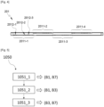
- the attenuation module 201 is configured to apply a sequence of attenuation combinations to the antenna 202.
- a combination of attenuations includes at least one attenuation of the gain of the antenna 202 on a frequency band of the maximum set of frequency bands.
- a combination of attenuations comprises for example an attenuation on the B3 frequency band and an attenuation on the B1 frequency band.
- FIG. 3 is a schematic representation of a first embodiment of the antenna 202 of the intelligent antenna system 200 according to the invention.
- Cavity 2022 has a through hole 2024 and coaxial cable 2023 is configured to pass through hole 3014 such that power can be connected to coaxial cable 2023 via its coaxial connector from outside cavity 2022.
- FIG. 4 is a schematic representation of a first embodiment of the attenuator 2010 of the intelligent antenna system 200 according to the invention.
- the attenuator 2011 comprises at least one strand notch filter, otherwise called "spur-line" in English.
- the attenuator 2011 has four strand notch filters 2011-1, 2011-2, 2011-3, 2011-4 in series.
- Each stranded notch filter 2011-1, 2011-2, 2011-3, 2011-4 comprises at least one PIN diode (for “Positive Intrinsic Negative diode”) acting as a switch.
- PIN diode for “Positive Intrinsic Negative diode”
- each strand notch filter 2011-1, 2011-2, 2011-3, 2011-4 comprises three PIN diodes 2012-1, 2012-2, 2012-3, only identified on the first strand notch filter 2011-1.
- the controller 2013 is configured to activate or deactivate the PIN diode(s) 2012-1, 2012-2, 2012-3 of each stranded notch filter 2011-1, 2011-2, 2011- 3, 2011-4 to increase or decrease the electrical length of the strand of the strand notch filter 2011-1, 2011-2, 2011-3, 2011-4.
- the smaller the size of the strand the greater the attenuation frequency by the strand notch filter 2011-1, 2011-2, 2011-3, 2011-4.
- the attenuator 2011 has a surface area approximately twice less than the surface area of the antenna 202 necessary to obtain a positive gain greater than 4 dB and the smallest possible volume for the antenna system 200.
- volume of the intelligent antenna system 202 is for example included in a parallelepiped of volume 10 cm x 10 cm x 2.5 cm.
- the attenuator 2011 can thus attenuate only on three different high frequency frequency bands, and to obtain a sufficient level of attenuation for a given frequency band, that is to say by at least 15 dB, the attenuator 2011 can only attenuate on two different frequency bands simultaneously at most.
- the attenuator 2011 comprises for each frequency band of the set of frequency bands, a notch filter corresponding to the frequency band.
- the notch filters of the 2011 attenuator are mounted in parallel.
- the notch filter is for example a comb filter, otherwise called a “hairpin filter” in English.
- the system card 203 is configured to control the controller 2013 by sending it programming instructions.
- the system card 203 is also configured to carry out measurements of upstream flow rates and downstream flow rates via the terminal 300 connected to the intelligent antenna system 200, that is to say by connecting to the internet via the connection sharing means of the terminal 300.
- the system card 203 is for example a SoM (for “System On Module”) system card.
- a first step 101 of the method 100 consists, for the terminal 300, of applying the rules and parameters received to select an initial frequency band from the maximum set of frequency bands.
- a second step 102 of the method 100 consists, for the system card 203, of measuring an initial upstream flow and an initial downstream flow on the initial frequency band, via the terminal 300.
- a third step 103 of the method 100 consists of choosing the initial upstream flow as the reference upstream flow and the initial downstream flow as the reference downstream flow.
- the sequence of attenuation combinations can be applied a plurality of times.
- the attenuation combinations are applied successively by the attenuation module 201.
- sequence of attenuation combinations may depend on at least one circumstantial information associated with the method 100 according to the invention.
- the circumstantial information is for example the time at which the process 100 is carried out or the location of the terminal 300.
- the fifth step 105 of the method 100 consists, for the system card 203, of measuring, via the terminal 300, an upstream flow on the frequency band selected by the terminal 300 corresponding to the combination of attenuations applied by the attenuation module 201 .
- the upstream flow can be measured after a predefined time interval.
- the fifth step 105 is preceded by a step of forcing a selection by the terminal 300 d 'a frequency band among the set of frequency bands.
- the forcing step is for example carried out by deactivating then reactivating the modem of the terminal 300.
- the sequence of attenuation combinations includes a first attenuation combination for which a first upstream rate is measured and a second attenuation combination for which a second upstream rate is measured. If the first measured upstream flow rate is greater than the second measured upstream flow rate, the sequence of attenuation combinations includes a third combination of attenuations whereas if the first measured upstream flow rate is less than the second measured upstream flow rate, the sequence of combinations of attenuations mitigations includes a fourth combination of mitigations, the third combination of mitigations being different from the fourth combination of mitigations.
- the sequence of combinations of attenuations comprises N combinations of attenuations and each combination of attenuations comprises N-1 attenuations applied on frequency bands of the maximum set of different frequency bands.
- the first embodiment corresponds to a case where the capabilities of the intelligent antenna system 200 do not limit the number of frequency bands that can be attenuated simultaneously.
- the first embodiment cannot therefore be implemented by the intelligent antenna system 200 presenting an attenuator 2011 according to the preferred embodiment.
- the maximum set of frequency bands comprises 4 frequency bands, B20, B3, B1, B7.
- each combination of attenuations comprises at most two attenuations applied to frequency bands of the maximum set of different frequency bands.
- the ninth step 109 consists of applying the fourth combination of attenuations to the antenna 202.
- the measured downflow rate is less than the downlink rate threshold, we are interested in the frequency band which gave the second best upstream rate, that is to say the upstream rate among the upstream rates measured in the fifth step 105 of method 100, the highest after the reference upstream rate obtained after the application of the sequence of attenuation combinations. If this frequency band is the initial frequency band, the initial frequency band corresponds to the optimal frequency band in terms of throughput. If this frequency band is different from the initial frequency band, the ninth step 109 and the tenth step of the method 100 are carried out for the combination of attenuations corresponding to this frequency band, and so on until the downward flow measured in the tenth step 110 is greater than or equal to the downstream flow threshold.
Landscapes
- Engineering & Computer Science (AREA)
- Computer Networks & Wireless Communication (AREA)
- Signal Processing (AREA)
- Transceivers (AREA)
- Circuits Of Receivers In General (AREA)
Claims (15)
- Verfahren (100), das die automatische Auswahl durch ein Endgerät (300) eines durchsatzoptimalen Frequenzbandes aus einem Satz von Frequenzbändern ermöglicht, die über das Endgerät (300) auswählbar sind, um eine Kommunikation mit einer Basisstation (400) aufzubauen, wobei der Satz von Frequenzbändern zu einem bekannten maximalen Satz von Frequenzbändern gehört, dadurch gekennzeichnet, dass das Endgerät (300) mit einem externen intelligenten Antennensystem (200) verbunden ist mit mindestens einer Antenne (202), einem Dämpfungsmodul (201) und einer Systemkarte (203), und dass das Verfahren (100) nach dem Empfang durch das Endgerät (300) mindestens einer Nachricht der Basisstation (400) mit einer Vielzahl von Regeln und Parametern, die vom Endgerät (300) anzuwenden sind, um ein Frequenzband aus dem Satz der Frequenzbänder auszuwählen, die folgenden Schritte umfasst:- Auswahl eines ursprünglichen Frequenzbandes durch das Endgerät (300) aus dem Satz von Frequenzbändern durch Anwendung der Vielzahl von Regeln und Parametern (101);- Messen eines ursprünglichen Upstream-Durchsatzes und eines ursprünglichen Downstream-Durchsatzes durch die Systemkarte (203) über das Endgerät (300) auf dem ursprünglichen Frequenzband (102);- Auswahl des ursprünglichen Upstream-Durchsatzes als Referenz-Upstream-Durchsatz und des ursprünglichen Downstream-Durchsatzes als Referenz-Downstream-Durchsatz (103);- Anwendung durch das Dämpfungsmodul (201) von mindestens einer Sequenz (1050) von Dämpfungskombinationen (1051_1, 1051_2, 1051_3) an der Antenne (202), wobei jede Dämpfungskombination (1051_1, 1051_2, 1051_3) mindestens eine Dämpfung des Antennengewinns (202) über ein gegebenes Frequenzband des maximalen Satzes von Frequenzbändern (104) umfasst:o Für jede angewendete Dämpfungskombination (1051_1, 1051_2, 1051_3) Messung eines Upstream-Durchsatzes (D1, D2, D3) durch die Systemkarte (203) über das Endgerät (300, 105):• Wenn der gemessene Upstream-Durchsatz (D1, D2, D3) strikt größer als ein Schwellenwert für den Upstream-Durchsatz ist, der vom Referenz-Upstream-Durchsatz abhängt, Auswahl des gemessenen Upstream-Durchsatzes (D1, D2, D3) als Referenz-Upstream-Durchsatz (106);- Wenn der Referenz-Upstream-Durchsatz größer als der ursprüngliche Upstream-Durchsatz ist, Anwendung der Dämpfungskombination (1051_1, 1051_2, 1051_3) entsprechend dem Referenz-Upstream-Durchsatz durch das Dämpfungsmodul (201, 109) auf die Antenne (202):o Messen eines Downstream-Durchsatzes durch die Systemkarte (203) über das Endgerät (300, 110):• Wenn der gemessene Downstream-Durchsatz größer oder gleich einem Schwellenwert für den Downstream-Durchsatz ist, der vom Referenz-Downstream-Durchsatz abhängt, entspricht die angewendete Dämpfungskombination (1051_1, 1051_2, 1051_3) dem durchsatzoptimalen Frequenzband.
- Verfahren (100) nach Anspruch 1, dadurch gekennzeichnet, dass, wenn der maximale Satz von Frequenzbändern N Frequenzbänder umfasst, die Sequenz (1050) von Dämpfungskombinationen (1051_1, 1051_2, 1051_3) N Dämpfungskombinationen (1051_1, 1051_2, 1051_3) umfasst, wobei jede Dämpfungskombination (1051_1, 1051_2, 1051_3) N-1 Dämpfungen umfasst, die auf unterschiedliche Frequenzbänder des maximalen Satzes von Frequenzbändern angewendet werden.
- Verfahren (100) nach Anspruch 1, dadurch gekennzeichnet, dass jede Dämpfungskombination (1051_1, 1051_2, 1051_3) höchstens zwei Dämpfungen umfasst, die auf Frequenzbänder des maximalen Satzes von unterschiedlichen Frequenzbändern angewendet werden.
- Verfahren (100) nach einem der vorhergehenden Ansprüche, dadurch gekennzeichnet, dass es außerdem einen Schritt (107) zur Identifizierung des durchsatzoptimalen Frequenzbandes umfasst.
- Verfahren (100) nach einem der vorhergehenden Ansprüche, dadurch gekennzeichnet, dass es mit mindestens einer von den Umständen abhängigen Information verknüpft ist.
- Verfahren (100) nach den Ansprüchen 4 und 5, dadurch gekennzeichnet, dass es einen Schritt (108) des Speicherns des identifizierten durchsatzoptimalen Frequenzbandes in einer Datenbank umfasst, wobei das durchsatzoptimale Frequenzband mit der von den Umständen abhängigen Information in der Datenbank verknüpft ist.
- Verfahren (100) nach Anspruch 6, dadurch gekennzeichnet, dass die Sequenz von Dämpfungskombinationen von der zugehörigen und von den Umständen abhängigen Information oder dem/den durchsatzoptimalen Frequenzband(en) abhängt, das/die der zugehörigen und von den Umständen abhängigen Information in der Datenbank entspricht/entsprechen.
- Verfahren (100) nach einem der vorhergehenden Ansprüche, dadurch gekennzeichnet, dass für das ursprüngliche Frequenzband und für jede angewendete Dämpfungskombination (1051_1, 1051_2, 1051_3) der Upstream- und/oder Downstreamdurchsatz (D1, D2, D3, D0) nach einem vordefinierten Zeitintervall gemessen wird.
- Verfahren (100) nach einem der vorhergehenden Ansprüche, dadurch gekennzeichnet, dass es durchgeführt wird, sobald eine Wiederholungsbedingung erfüllt ist, wobei die Bedingung von einem Taktgeber, einer erfassbaren Umgebungsänderung oder einer signifikanten Änderung des Durchsatzes in Bezug zu einem erwarteten Durchsatz abhängt.
- Verfahren (100) nach einem der vorhergehenden Ansprüche, dadurch gekennzeichnet, dass es einen Schritt des Auslösens einer Auswahl durch das Endgerät (300) eines Frequenzbandes aus der Gesamtheit der Frequenzbänder nach jeder Anwendung einer Dämpfungskombination (1051_1, 1051_2, 1051_3) umfasst.
- System System (500) zur Durchführung des Verfahrens (100) gemäß einem der vorhergehenden Ansprüche, wobei das System umfasst:- ein Endgerät (300) mit mindestens einem Antennenanschluss (301), der so konfiguriert ist, dass er eine Verbindung zwischen einem intelligenten Antennensystem (200) und dem Endgerät (300) ermöglicht;- ein intelligentes Antennensystem (200) mit:o einer Antenne (202);o einem Dämpfungsmodul (201) mit:• einem programmierbaren Dämpfungsglied (2010), das so konfiguriert ist, dass es auf die Antenne (202) eine Sequenz (1050) von Dämpfungskombinationen (1051_1, 1051_2, 1051_3) anwendet, wobei jede Dämpfungskombination (1051_1, 1051_2, 1051_3) mindestens eine Dämpfung des Antennengewinns (202) an einem gegebenen Frequenzband umfasst;• einer Steuereinheit (2013), die so konfiguriert ist, dass sie das Dämpfungsglied (2010) programmiert;o einer Systemkarte (203), die so konfiguriert ist, dass sie die Steuereinheit (2013) steuert und Messungen von Upstream- und Downstream-Durchsätzen über das Endgerät (300) durchführt, wenn das System (200) über den Antennenanschluss (301) mit dem Endgerät verbunden ist.
- System (500) nach Anspruch 11, dadurch gekennzeichnet, dass das Dämpfungsglied (2011) mindestens ein Strang-Bandsperrfilter (2011-1, 2011-2, 2011-3, 2011-4) und mindestens eine PIN-Diode (2012-1, 2012-2, 2012-3) umfasst, wobei die Steuereinheit (2013) so konfiguriert ist, dass sie die PIN-Diode (2012-1, 2012-2, 2012-3) aktiviert oder deaktiviert, um die elektrische Länge des Strangs des Strang-Bandsperrfilters (2011-1, 2011-2, 2011-3, 2011-4) zu erhöhen oder zu verringern.
- System (500) nach Anspruch 12, dadurch gekennzeichnet, dass das Dämpfungsglied (2010) eine Vielzahl von Strang-Bandsperrfiltern (2011-1, 2011-2, 2011-3, 2011-4) in Reihe aufweist.
- System (500) nach einem der Ansprüche 11 bis 13, dadurch gekennzeichnet, dass die Antenne (202) Folgendes umfasst:- ein spiralförmiges Breitband-Antennenelement (2021);- eine Stromversorgung, die so konfiguriert ist, dass sie das Antennenelement (2021) über ein Koaxialkabel (2023) mit Strom versorgt;- einen Hohlraum (2022), der das Antennenelement (2021) und ein Durchgangsloch (2024) umfasst;wobei das Koaxialkabel (2023) so konfiguriert ist, dass es durch das Loch (2024) verläuft, so dass sich die Stromversorgung außerhalb des Hohlraums (2022) befindet.
- System (500) nach Anspruch 14, dadurch gekennzeichnet, dass die Stromversorgung einen unendlichen Balun (2025) umfasst.
Applications Claiming Priority (2)
| Application Number | Priority Date | Filing Date | Title |
|---|---|---|---|
| FR2005158A FR3110803B1 (fr) | 2020-05-20 | 2020-05-20 | Système et procédé permettant la sélection par un terminal d’une bande fréquentielle optimale en termes de débit |
| PCT/EP2021/063019 WO2021233843A1 (fr) | 2020-05-20 | 2021-05-17 | Système et procédé permettant la sélection par un terminal d'une bande fréquentielle optimale en termes de débit |
Publications (2)
| Publication Number | Publication Date |
|---|---|
| EP4154628A1 EP4154628A1 (de) | 2023-03-29 |
| EP4154628B1 true EP4154628B1 (de) | 2024-07-10 |
Family
ID=72470476
Family Applications (1)
| Application Number | Title | Priority Date | Filing Date |
|---|---|---|---|
| EP21725209.7A Active EP4154628B1 (de) | 2020-05-20 | 2021-05-17 | System und verfahren zur auswahl eines optimalen frequenzbandes hinsichtlich der geschwindigkeit unter verwendung eines endgeräts |
Country Status (3)
| Country | Link |
|---|---|
| EP (1) | EP4154628B1 (de) |
| FR (1) | FR3110803B1 (de) |
| WO (1) | WO2021233843A1 (de) |
Families Citing this family (2)
| Publication number | Priority date | Publication date | Assignee | Title |
|---|---|---|---|---|
| CN114567910B (zh) * | 2022-02-23 | 2025-12-12 | 北京小米移动软件有限公司 | 无线网络的确定方法、装置、电子设备及存储介质 |
| CN116095843A (zh) * | 2022-12-20 | 2023-05-09 | 合肥途鸽科技有限公司 | 一种上行链路优化方法和系统 |
Family Cites Families (2)
| Publication number | Priority date | Publication date | Assignee | Title |
|---|---|---|---|---|
| US9554359B2 (en) * | 2014-02-07 | 2017-01-24 | Apple Inc. | Dynamic antenna tuner setting for carrier aggregation scenarios |
| US10893559B2 (en) * | 2018-05-03 | 2021-01-12 | Apple Inc. | Frequency selection during activity |
-
2020
- 2020-05-20 FR FR2005158A patent/FR3110803B1/fr not_active Expired - Fee Related
-
2021
- 2021-05-17 WO PCT/EP2021/063019 patent/WO2021233843A1/fr not_active Ceased
- 2021-05-17 EP EP21725209.7A patent/EP4154628B1/de active Active
Also Published As
| Publication number | Publication date |
|---|---|
| EP4154628A1 (de) | 2023-03-29 |
| WO2021233843A1 (fr) | 2021-11-25 |
| FR3110803A1 (fr) | 2021-11-26 |
| FR3110803B1 (fr) | 2022-05-20 |
Similar Documents
| Publication | Publication Date | Title |
|---|---|---|
| EP4154628B1 (de) | System und verfahren zur auswahl eines optimalen frequenzbandes hinsichtlich der geschwindigkeit unter verwendung eines endgeräts | |
| EP0717912B1 (de) | Verfahren zum langeren betrieb eines funkrufempfanger und empfanger hierzu | |
| EP3491742B1 (de) | Koexistenz von funkmodulen in einer elektronischen vorrichtung | |
| FR2936365A1 (fr) | Dispositif antennaire autonome a commutation de pointage rapide | |
| WO2023161218A1 (fr) | Activation automatique d'un point d'accès 6ghz | |
| FR3095915A1 (fr) | Procédé d’émission avec accès LBT au canal, dispositif et programme correspondants | |
| FR3133721A1 (fr) | Procede ameliore de selection d’un canal de communication entre un aeronef et une station distante, et systeme de communication executant le procede. | |
| FR2703867A1 (fr) | Dispositif de synchronisation pour un terminal d'un système de radiocommunication. | |
| WO2024126480A1 (fr) | Procédé de réduction de la consommation énergétique d'un point d'accès wi-fi dans un réseau de communication. | |
| FR3091127A1 (fr) | Equipement électrique qui accède, dans un mode de fonctionnement alternatif, à un réseau de téléphonie mobile. | |
| WO2021116572A1 (fr) | Procédé et dispositif mettant en œuvre ce procédé pour accéder à un canal partagé pour répondre à une requête de demande de relais | |
| EP3066867B1 (de) | Verfahren zur herstellung einer verbindung zwischen einem mobilkommunikationsobjekt und einem entfernten server | |
| WO2018095954A1 (fr) | Sélection d'une infrastructure de télécommunication | |
| EP1981244A1 (de) | Verfahren zum Beginn einer Telekonferenzsession von einer Vorrichtung auf einem ersten Netz aus über ein zweites Netz sowie entsprechende elektronische Vorrichtung und elektronisches System | |
| FR2946205A1 (fr) | Amelioration du debit en communications radiofrequences | |
| EP2073450A1 (de) | Verfahren zur Kommunikation zwischen einem Endgerät und einem Kommunikationsnetz | |
| BE1020800A3 (fr) | Procede de declenchement d'une operation de selection de reseau par un terminal de communication. | |
| EP3389232A1 (de) | Verfahren zur konfiguration von nachrichtenverbreitung | |
| FR2834606A1 (fr) | Procede et dispositif de communication dans un reseau | |
| WO2024115215A1 (fr) | Réseau radio courte portée avec paramètre de connectivité | |
| WO2025103815A1 (fr) | Procédé de configuration d'un système de communication permettant de caractériser le nombre de canaux de transmission d'un signal radio émis par un point d'accès appartenant au système de communication destinés à être alloués à un équipement utilisateur, dispositif et programme d'ordinateur correspondant | |
| WO2025103792A1 (fr) | Procédé de configuration d'un système de communication permettant de contrôler la couverture d'un point d'accès lorsqu'un ensemble de surfaces intelligentes reconfigurables est déployé, dispositif et programme d'ordinateur correspondants | |
| FR3146256A1 (fr) | Procédé de sélection automatique du canal de fonctionnement d’un point d’accès WIFI. | |
| WO2020002037A1 (fr) | Procede de gestion d'un canal de communication en cas de détection d'un signal radar | |
| FR2917561A1 (fr) | Modification de quantite de ressource equivalente lors de la phase de controle d'admission de connexion dans une partie d'un reseau de telecommunication. |
Legal Events
| Date | Code | Title | Description |
|---|---|---|---|
| STAA | Information on the status of an ep patent application or granted ep patent |
Free format text: STATUS: UNKNOWN |
|
| STAA | Information on the status of an ep patent application or granted ep patent |
Free format text: STATUS: THE INTERNATIONAL PUBLICATION HAS BEEN MADE |
|
| PUAI | Public reference made under article 153(3) epc to a published international application that has entered the european phase |
Free format text: ORIGINAL CODE: 0009012 |
|
| STAA | Information on the status of an ep patent application or granted ep patent |
Free format text: STATUS: REQUEST FOR EXAMINATION WAS MADE |
|
| 17P | Request for examination filed |
Effective date: 20221125 |
|
| AK | Designated contracting states |
Kind code of ref document: A1 Designated state(s): AL AT BE BG CH CY CZ DE DK EE ES FI FR GB GR HR HU IE IS IT LI LT LU LV MC MK MT NL NO PL PT RO RS SE SI SK SM TR |
|
| DAV | Request for validation of the european patent (deleted) | ||
| DAX | Request for extension of the european patent (deleted) | ||
| RIC1 | Information provided on ipc code assigned before grant |
Ipc: H04W 72/0453 20230101ALN20231129BHEP Ipc: H04W 48/18 20090101ALN20231129BHEP Ipc: H04W 72/02 20090101AFI20231129BHEP |
|
| RIC1 | Information provided on ipc code assigned before grant |
Ipc: H04W 72/0453 20230101ALN20231205BHEP Ipc: H04W 48/18 20090101ALN20231205BHEP Ipc: H04W 72/02 20090101AFI20231205BHEP |
|
| GRAP | Despatch of communication of intention to grant a patent |
Free format text: ORIGINAL CODE: EPIDOSNIGR1 |
|
| STAA | Information on the status of an ep patent application or granted ep patent |
Free format text: STATUS: GRANT OF PATENT IS INTENDED |
|
| INTG | Intention to grant announced |
Effective date: 20240122 |
|
| GRAS | Grant fee paid |
Free format text: ORIGINAL CODE: EPIDOSNIGR3 |
|
| GRAA | (expected) grant |
Free format text: ORIGINAL CODE: 0009210 |
|
| STAA | Information on the status of an ep patent application or granted ep patent |
Free format text: STATUS: THE PATENT HAS BEEN GRANTED |
|
| AK | Designated contracting states |
Kind code of ref document: B1 Designated state(s): AL AT BE BG CH CY CZ DE DK EE ES FI FR GB GR HR HU IE IS IT LI LT LU LV MC MK MT NL NO PL PT RO RS SE SI SK SM TR |
|
| REG | Reference to a national code |
Ref country code: CH Ref legal event code: EP |
|
| REG | Reference to a national code |
Ref country code: DE Ref legal event code: R096 Ref document number: 602021015501 Country of ref document: DE |
|
| REG | Reference to a national code |
Ref country code: LT Ref legal event code: MG9D |
|
| REG | Reference to a national code |
Ref country code: NL Ref legal event code: MP Effective date: 20240710 |
|
| PG25 | Lapsed in a contracting state [announced via postgrant information from national office to epo] |
Ref country code: PT Free format text: LAPSE BECAUSE OF FAILURE TO SUBMIT A TRANSLATION OF THE DESCRIPTION OR TO PAY THE FEE WITHIN THE PRESCRIBED TIME-LIMIT Effective date: 20241111 |
|
| REG | Reference to a national code |
Ref country code: AT Ref legal event code: MK05 Ref document number: 1703134 Country of ref document: AT Kind code of ref document: T Effective date: 20240710 |
|
| PG25 | Lapsed in a contracting state [announced via postgrant information from national office to epo] |
Ref country code: NL Free format text: LAPSE BECAUSE OF FAILURE TO SUBMIT A TRANSLATION OF THE DESCRIPTION OR TO PAY THE FEE WITHIN THE PRESCRIBED TIME-LIMIT Effective date: 20240710 |
|
| PG25 | Lapsed in a contracting state [announced via postgrant information from national office to epo] |
Ref country code: PT Free format text: LAPSE BECAUSE OF FAILURE TO SUBMIT A TRANSLATION OF THE DESCRIPTION OR TO PAY THE FEE WITHIN THE PRESCRIBED TIME-LIMIT Effective date: 20241111 Ref country code: NL Free format text: LAPSE BECAUSE OF FAILURE TO SUBMIT A TRANSLATION OF THE DESCRIPTION OR TO PAY THE FEE WITHIN THE PRESCRIBED TIME-LIMIT Effective date: 20240710 |
|
| PG25 | Lapsed in a contracting state [announced via postgrant information from national office to epo] |
Ref country code: NO Free format text: LAPSE BECAUSE OF FAILURE TO SUBMIT A TRANSLATION OF THE DESCRIPTION OR TO PAY THE FEE WITHIN THE PRESCRIBED TIME-LIMIT Effective date: 20241010 |
|
| PG25 | Lapsed in a contracting state [announced via postgrant information from national office to epo] |
Ref country code: FI Free format text: LAPSE BECAUSE OF FAILURE TO SUBMIT A TRANSLATION OF THE DESCRIPTION OR TO PAY THE FEE WITHIN THE PRESCRIBED TIME-LIMIT Effective date: 20240710 Ref country code: GR Free format text: LAPSE BECAUSE OF FAILURE TO SUBMIT A TRANSLATION OF THE DESCRIPTION OR TO PAY THE FEE WITHIN THE PRESCRIBED TIME-LIMIT Effective date: 20241011 Ref country code: PL Free format text: LAPSE BECAUSE OF FAILURE TO SUBMIT A TRANSLATION OF THE DESCRIPTION OR TO PAY THE FEE WITHIN THE PRESCRIBED TIME-LIMIT Effective date: 20240710 |
|
| PG25 | Lapsed in a contracting state [announced via postgrant information from national office to epo] |
Ref country code: BG Free format text: LAPSE BECAUSE OF FAILURE TO SUBMIT A TRANSLATION OF THE DESCRIPTION OR TO PAY THE FEE WITHIN THE PRESCRIBED TIME-LIMIT Effective date: 20240710 |
|
| PG25 | Lapsed in a contracting state [announced via postgrant information from national office to epo] |
Ref country code: LV Free format text: LAPSE BECAUSE OF FAILURE TO SUBMIT A TRANSLATION OF THE DESCRIPTION OR TO PAY THE FEE WITHIN THE PRESCRIBED TIME-LIMIT Effective date: 20240710 |
|
| PG25 | Lapsed in a contracting state [announced via postgrant information from national office to epo] |
Ref country code: AT Free format text: LAPSE BECAUSE OF FAILURE TO SUBMIT A TRANSLATION OF THE DESCRIPTION OR TO PAY THE FEE WITHIN THE PRESCRIBED TIME-LIMIT Effective date: 20240710 Ref country code: IS Free format text: LAPSE BECAUSE OF FAILURE TO SUBMIT A TRANSLATION OF THE DESCRIPTION OR TO PAY THE FEE WITHIN THE PRESCRIBED TIME-LIMIT Effective date: 20241110 |
|
| PG25 | Lapsed in a contracting state [announced via postgrant information from national office to epo] |
Ref country code: HR Free format text: LAPSE BECAUSE OF FAILURE TO SUBMIT A TRANSLATION OF THE DESCRIPTION OR TO PAY THE FEE WITHIN THE PRESCRIBED TIME-LIMIT Effective date: 20240710 |
|
| PG25 | Lapsed in a contracting state [announced via postgrant information from national office to epo] |
Ref country code: RS Free format text: LAPSE BECAUSE OF FAILURE TO SUBMIT A TRANSLATION OF THE DESCRIPTION OR TO PAY THE FEE WITHIN THE PRESCRIBED TIME-LIMIT Effective date: 20241010 Ref country code: ES Free format text: LAPSE BECAUSE OF FAILURE TO SUBMIT A TRANSLATION OF THE DESCRIPTION OR TO PAY THE FEE WITHIN THE PRESCRIBED TIME-LIMIT Effective date: 20240710 |
|
| PG25 | Lapsed in a contracting state [announced via postgrant information from national office to epo] |
Ref country code: RS Free format text: LAPSE BECAUSE OF FAILURE TO SUBMIT A TRANSLATION OF THE DESCRIPTION OR TO PAY THE FEE WITHIN THE PRESCRIBED TIME-LIMIT Effective date: 20241010 Ref country code: PL Free format text: LAPSE BECAUSE OF FAILURE TO SUBMIT A TRANSLATION OF THE DESCRIPTION OR TO PAY THE FEE WITHIN THE PRESCRIBED TIME-LIMIT Effective date: 20240710 Ref country code: NO Free format text: LAPSE BECAUSE OF FAILURE TO SUBMIT A TRANSLATION OF THE DESCRIPTION OR TO PAY THE FEE WITHIN THE PRESCRIBED TIME-LIMIT Effective date: 20241010 Ref country code: LV Free format text: LAPSE BECAUSE OF FAILURE TO SUBMIT A TRANSLATION OF THE DESCRIPTION OR TO PAY THE FEE WITHIN THE PRESCRIBED TIME-LIMIT Effective date: 20240710 Ref country code: IS Free format text: LAPSE BECAUSE OF FAILURE TO SUBMIT A TRANSLATION OF THE DESCRIPTION OR TO PAY THE FEE WITHIN THE PRESCRIBED TIME-LIMIT Effective date: 20241110 Ref country code: HR Free format text: LAPSE BECAUSE OF FAILURE TO SUBMIT A TRANSLATION OF THE DESCRIPTION OR TO PAY THE FEE WITHIN THE PRESCRIBED TIME-LIMIT Effective date: 20240710 Ref country code: GR Free format text: LAPSE BECAUSE OF FAILURE TO SUBMIT A TRANSLATION OF THE DESCRIPTION OR TO PAY THE FEE WITHIN THE PRESCRIBED TIME-LIMIT Effective date: 20241011 Ref country code: FI Free format text: LAPSE BECAUSE OF FAILURE TO SUBMIT A TRANSLATION OF THE DESCRIPTION OR TO PAY THE FEE WITHIN THE PRESCRIBED TIME-LIMIT Effective date: 20240710 Ref country code: ES Free format text: LAPSE BECAUSE OF FAILURE TO SUBMIT A TRANSLATION OF THE DESCRIPTION OR TO PAY THE FEE WITHIN THE PRESCRIBED TIME-LIMIT Effective date: 20240710 Ref country code: BG Free format text: LAPSE BECAUSE OF FAILURE TO SUBMIT A TRANSLATION OF THE DESCRIPTION OR TO PAY THE FEE WITHIN THE PRESCRIBED TIME-LIMIT Effective date: 20240710 Ref country code: AT Free format text: LAPSE BECAUSE OF FAILURE TO SUBMIT A TRANSLATION OF THE DESCRIPTION OR TO PAY THE FEE WITHIN THE PRESCRIBED TIME-LIMIT Effective date: 20240710 |
|
| REG | Reference to a national code |
Ref country code: DE Ref legal event code: R097 Ref document number: 602021015501 Country of ref document: DE |
|
| PG25 | Lapsed in a contracting state [announced via postgrant information from national office to epo] |
Ref country code: SM Free format text: LAPSE BECAUSE OF FAILURE TO SUBMIT A TRANSLATION OF THE DESCRIPTION OR TO PAY THE FEE WITHIN THE PRESCRIBED TIME-LIMIT Effective date: 20240710 Ref country code: DK Free format text: LAPSE BECAUSE OF FAILURE TO SUBMIT A TRANSLATION OF THE DESCRIPTION OR TO PAY THE FEE WITHIN THE PRESCRIBED TIME-LIMIT Effective date: 20240710 Ref country code: RO Free format text: LAPSE BECAUSE OF FAILURE TO SUBMIT A TRANSLATION OF THE DESCRIPTION OR TO PAY THE FEE WITHIN THE PRESCRIBED TIME-LIMIT Effective date: 20240710 |
|
| PG25 | Lapsed in a contracting state [announced via postgrant information from national office to epo] |
Ref country code: EE Free format text: LAPSE BECAUSE OF FAILURE TO SUBMIT A TRANSLATION OF THE DESCRIPTION OR TO PAY THE FEE WITHIN THE PRESCRIBED TIME-LIMIT Effective date: 20240710 |
|
| PG25 | Lapsed in a contracting state [announced via postgrant information from national office to epo] |
Ref country code: CZ Free format text: LAPSE BECAUSE OF FAILURE TO SUBMIT A TRANSLATION OF THE DESCRIPTION OR TO PAY THE FEE WITHIN THE PRESCRIBED TIME-LIMIT Effective date: 20240710 |
|
| PG25 | Lapsed in a contracting state [announced via postgrant information from national office to epo] |
Ref country code: SK Free format text: LAPSE BECAUSE OF FAILURE TO SUBMIT A TRANSLATION OF THE DESCRIPTION OR TO PAY THE FEE WITHIN THE PRESCRIBED TIME-LIMIT Effective date: 20240710 Ref country code: IT Free format text: LAPSE BECAUSE OF FAILURE TO SUBMIT A TRANSLATION OF THE DESCRIPTION OR TO PAY THE FEE WITHIN THE PRESCRIBED TIME-LIMIT Effective date: 20240710 |
|
| PLBE | No opposition filed within time limit |
Free format text: ORIGINAL CODE: 0009261 |
|
| STAA | Information on the status of an ep patent application or granted ep patent |
Free format text: STATUS: NO OPPOSITION FILED WITHIN TIME LIMIT |
|
| 26N | No opposition filed |
Effective date: 20250411 |
|
| PGFP | Annual fee paid to national office [announced via postgrant information from national office to epo] |
Ref country code: DE Payment date: 20250626 Year of fee payment: 5 |
|
| PGFP | Annual fee paid to national office [announced via postgrant information from national office to epo] |
Ref country code: GB Payment date: 20250528 Year of fee payment: 5 |
|
| PGFP | Annual fee paid to national office [announced via postgrant information from national office to epo] |
Ref country code: FR Payment date: 20250528 Year of fee payment: 5 |
|
| PG25 | Lapsed in a contracting state [announced via postgrant information from national office to epo] |
Ref country code: SE Free format text: LAPSE BECAUSE OF FAILURE TO SUBMIT A TRANSLATION OF THE DESCRIPTION OR TO PAY THE FEE WITHIN THE PRESCRIBED TIME-LIMIT Effective date: 20240710 |
|
| REG | Reference to a national code |
Ref country code: CH Ref legal event code: H13 Free format text: ST27 STATUS EVENT CODE: U-0-0-H10-H13 (AS PROVIDED BY THE NATIONAL OFFICE) Effective date: 20251223 |
|
| PG25 | Lapsed in a contracting state [announced via postgrant information from national office to epo] |
Ref country code: LU Free format text: LAPSE BECAUSE OF NON-PAYMENT OF DUE FEES Effective date: 20250517 |
|
| PG25 | Lapsed in a contracting state [announced via postgrant information from national office to epo] |
Ref country code: CH Free format text: LAPSE BECAUSE OF NON-PAYMENT OF DUE FEES Effective date: 20250531 |
|
| PG25 | Lapsed in a contracting state [announced via postgrant information from national office to epo] |
Ref country code: MC Free format text: LAPSE BECAUSE OF FAILURE TO SUBMIT A TRANSLATION OF THE DESCRIPTION OR TO PAY THE FEE WITHIN THE PRESCRIBED TIME-LIMIT Effective date: 20240710 |