EP4154512B1 - Verzerrung für laserstrahlabtastanzeigen mit augenverfolgung - Google Patents
Verzerrung für laserstrahlabtastanzeigen mit augenverfolgung Download PDFInfo
- Publication number
- EP4154512B1 EP4154512B1 EP21809743.4A EP21809743A EP4154512B1 EP 4154512 B1 EP4154512 B1 EP 4154512B1 EP 21809743 A EP21809743 A EP 21809743A EP 4154512 B1 EP4154512 B1 EP 4154512B1
- Authority
- EP
- European Patent Office
- Prior art keywords
- pupils
- viewer
- display device
- pixels
- image frame
- Prior art date
- Legal status (The legal status is an assumption and is not a legal conclusion. Google has not performed a legal analysis and makes no representation as to the accuracy of the status listed.)
- Active
Links
Images


Classifications
-
- G—PHYSICS
- G06—COMPUTING OR CALCULATING; COUNTING
- G06F—ELECTRIC DIGITAL DATA PROCESSING
- G06F3/00—Input arrangements for transferring data to be processed into a form capable of being handled by the computer; Output arrangements for transferring data from processing unit to output unit, e.g. interface arrangements
- G06F3/01—Input arrangements or combined input and output arrangements for interaction between user and computer
- G06F3/011—Arrangements for interaction with the human body, e.g. for user immersion in virtual reality
- G06F3/012—Head tracking input arrangements
-
- G—PHYSICS
- G09—EDUCATION; CRYPTOGRAPHY; DISPLAY; ADVERTISING; SEALS
- G09G—ARRANGEMENTS OR CIRCUITS FOR CONTROL OF INDICATING DEVICES USING STATIC MEANS TO PRESENT VARIABLE INFORMATION
- G09G3/00—Control arrangements or circuits, of interest only in connection with visual indicators other than cathode-ray tubes
- G09G3/007—Use of pixel shift techniques, e.g. by mechanical shift of the physical pixels or by optical shift of the perceived pixels
-
- G—PHYSICS
- G06—COMPUTING OR CALCULATING; COUNTING
- G06F—ELECTRIC DIGITAL DATA PROCESSING
- G06F3/00—Input arrangements for transferring data to be processed into a form capable of being handled by the computer; Output arrangements for transferring data from processing unit to output unit, e.g. interface arrangements
- G06F3/01—Input arrangements or combined input and output arrangements for interaction between user and computer
- G06F3/011—Arrangements for interaction with the human body, e.g. for user immersion in virtual reality
- G06F3/013—Eye tracking input arrangements
-
- G—PHYSICS
- G06—COMPUTING OR CALCULATING; COUNTING
- G06T—IMAGE DATA PROCESSING OR GENERATION, IN GENERAL
- G06T3/00—Geometric image transformations in the plane of the image
- G06T3/18—Image warping, e.g. rearranging pixels individually
-
- G—PHYSICS
- G09—EDUCATION; CRYPTOGRAPHY; DISPLAY; ADVERTISING; SEALS
- G09G—ARRANGEMENTS OR CIRCUITS FOR CONTROL OF INDICATING DEVICES USING STATIC MEANS TO PRESENT VARIABLE INFORMATION
- G09G3/00—Control arrangements or circuits, of interest only in connection with visual indicators other than cathode-ray tubes
- G09G3/02—Control arrangements or circuits, of interest only in connection with visual indicators other than cathode-ray tubes by tracing or scanning a light beam on a screen
-
- G—PHYSICS
- G09—EDUCATION; CRYPTOGRAPHY; DISPLAY; ADVERTISING; SEALS
- G09G—ARRANGEMENTS OR CIRCUITS FOR CONTROL OF INDICATING DEVICES USING STATIC MEANS TO PRESENT VARIABLE INFORMATION
- G09G2354/00—Aspects of interface with display user
-
- G—PHYSICS
- G09—EDUCATION; CRYPTOGRAPHY; DISPLAY; ADVERTISING; SEALS
- G09G—ARRANGEMENTS OR CIRCUITS FOR CONTROL OF INDICATING DEVICES USING STATIC MEANS TO PRESENT VARIABLE INFORMATION
- G09G3/00—Control arrangements or circuits, of interest only in connection with visual indicators other than cathode-ray tubes
- G09G3/20—Control arrangements or circuits, of interest only in connection with visual indicators other than cathode-ray tubes for presentation of an assembly of a number of characters, e.g. a page, by composing the assembly by combination of individual elements arranged in a matrix no fixed position being assigned to or needed to be assigned to the individual characters or partial characters
- G09G3/2007—Display of intermediate tones
- G09G3/2018—Display of intermediate tones by time modulation using two or more time intervals
- G09G3/2022—Display of intermediate tones by time modulation using two or more time intervals using sub-frames
- G09G3/2025—Display of intermediate tones by time modulation using two or more time intervals using sub-frames the sub-frames having all the same time duration
Definitions
- AR augmented reality
- a VR scenario typically involves presentation of digital or virtual image information without transparency to actual real-world visual input.
- An AR scenario typically involves presentation of digital or virtual image information as an augmentation to visualization of the real world around the user (i.e., transparency to real-world visual input). Accordingly, AR scenarios involve presentation of digital or virtual image information with transparency to the real-world visual input.
- MR Mixed reality
- a user 100 of an MR device 102 including a headset sees a real-world, physical object 104.
- a virtual object 114 may be rendered on a near-eye display device (e.g. a laser beam scanning display device) of the MR device 102 with respect to the real-world object 104.
- the real-world object 104 may be in the form of a table, and a virtual fairy (as an exemplary virtual object 114) may be rendered on the display device as being placed on the table.
- the MR device 102 must also account for the user's gaze (e.g. line of sight) used to generate/render the real-world object 104 as well as the virtual object 114.
- the user 100 may move their eyes from a first position providing a first field of view 105 to a second position providing a second field of view 106. While the position of the real-world object 104 remains the same with respect to the real-world coordinates, the position of the real-world object 104 shifts within the field of view of the user (e.g. the real-world object 104 is closer to the edge of the first field of view 105 and is in the middle of the second field of view 106).
- the change in user's pupil position may result in the virtual object 114 to appear slewed or broken (e.g. misstitched) on near-eye display device of the MR device 102.
- These artefacts on the displayed image frame are discussed below in greater detail.
- data from an eye tracking device 108 coupled to the MR device 102 may be used to render the virtual object 114 properly on the near-eye display device.
- Such eye tracking data may, for example, be discerned by projecting light at the end user's eyes, and detecting the return or reflection of at least some of that projected light.
- the eye tracking device 108 may output the pixel index of the display device where the user's gaze is directed at. For example, the eye tracking device 108 may determine a first position of the user's pupils as the center pixel of the display device at time t 1 and a second position of the user's pupils as 10 pixels to the right of the center pixel at time t 2 .
- the MR device 102 may be able to calculate the eye velocity for the user as a function of the first position, the second position and the difference ⁇ t between time t 1 and time t 2 .
- the system may calculate a different eye velocity for each unit of the scanning pattern (e.g. different eye velocity for each row, if scanning per row).
- the MR device 102 may obtain a first image frame corresponding to a first position of the user's pupils (illustrated by normal vector 115 to user's pupils) associated with the first field of view 105.
- the MR device 102 may receive data from the eye tracking device 108 and determine a second position (illustrated by normal vector 116 to user's pupils) of the user's pupils associated with the second field of view 106 using the data from the eye tracking device 108.
- the MR device 102 may then generate a second image frame corresponding to the second field of view 106 by performing, among other steps, a shift of one or more sets of pixels (e.g. rows) of the second image based at least on the first position, and the second position of the user's pupils.
- the second image frame may be generated using a head pose based warp, and the pixels of the second image frame may be shifted as described herein to correct the visual artefacts.
- the details of the shift, as well as the additional steps that may be performed, are described below in greater detail.
- FIG. 2 is a schematic representation of an exemplary AR/VR headset 200 with respect to an eyeball of a user of the headset 200.
- the headset 200 includes a display device 202 (e.g. a laser beam scanning display) which is positioned in front of the user's eyeball 204.
- An eye tracking device coupled to the headset 200 may track the position of the user's eyeball 204 (e.g. user's pupils).
- the user's line of sight 208 may be directed to a real or a virtual object 206.
- data from the eye tracking device may be used to correctly render the real or a virtual object 206 on the display device 202 based on the user's line of sight or any change in the user's line of sight. For example, if different sets of pixels (e.g. different rows) of the rendered image frame may be shifted by different shift values to generate the image frame to be displayed on the laser beam scanning display device.
- the shift values may be determined based on the data provided by the eye tracking device.
- the MR system may calculate the eye velocity of the user's pupils. A different eye velocity value may be calculated for each shift (e.g. in case of a per-row shift, a different eye velocity may be used for each row).
- FIG. 3 illustrates an exemplary method for transforming an image frame based on a position of pupils of a user (e.g. a viewer).
- the computing device obtains a first image frame corresponding to a first view perspective associated with a first position of the pupils of the viewer.
- the computing device may be coupled to a near-eye display device including a laser beam scanning display that displays data on pixels of the near-eye display device according to a predetermined scanning pattern. The data is displayed on a first set of pixels of the near-eye display device at a different moment in time than on a second set of pixels of the near-eye display device.
- the computing device may receive data associated with the viewer's pupil position from an eye tracking device coupled to the headset that the viewer is wearing.
- the computing device may determine a second position of the pupils of the viewer based on the data received from the eye tracking device.
- the second position of the viewer's pupils is associated with the second view perspective.
- the position of the viewer's pupils may be determined with respect to a head position of the viewer.
- the position of the viewer's pupils may be determined with respect to the headset (e.g. with respect to the pixels of the display device of the headset).
- the computing device may estimate a second head position that is also associated with a second view perspective.
- the computing device may generate an intermediary warped image frame from the first image frame using the second head position of the viewer. Accordingly, the intermediary warped image is generated using head pose based warp.
- a virtual object e.g. a virtual fairy
- the user looks at the virtual object, and fixes their gaze on the virtual object while the user turns their head/neck to face the virtual object. While the user rotates their head, the virtual object remains stationary, and the user's gaze is fixed on the virtual object.
- the system may then calculate an eye velocity (e.g. velocity of the user's pupils with respect to the headset or display device worn by the user) in x and y pixels for each unit of the scan pattern (e.g. each row) to shift the sets of pixels (e.g. rows) relative to the rendered frame.
- the final drawing (i.e. drawing 8) of FIG. 11 illustrates the final rendering of the image frame in continuous-time simulation on the display device.
- the object 1112 looks identical to the virtual object 400 illustrated in FIG. 4 . As illustrated in the drawings of FIG. 11 , the pixels all appear on the line of sight of the user, eliminating the visual artefacts on the displayed image frame (as illustrated in drawing 8 of FIG. 11 ).
- the third scenario exemplifies how rendering and image display gets complicated when the virtual object is in motion.
- the head pose based warping is not enough to correct the slew and the misstitch on the displayed image.
- the next scenario illustrates that in certain cases, the head pose based warping not only is not enough to correct the artefacts, but also makes the quality of the displayed image worse.
- a virtual object e.g. a virtual fish
- the user turns their whole body to follow the virtual object.
- Both the headset and the user's pupils are rotating relative to the real world, but are fixed relative to each other.
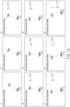
- FIG. 12 illustrates a series of drawings (drawings 1-8) illustrating the headset and pupil movement while remaining fixed relative to each other, along with the rendered image rendered on the display device. Head pose warp is not applied in the drawings illustrated in FIG. 12 .
- the headset 200 including the display device 202) as well as the user's gaze illustrated in FIG. 12 move counter-clockwise along with the virtual object 206, the user's line of sight 208, as well as the normal vector to the display device 202 remain fixed on the virtual object 206.
- the first set of pixels 1202 are formed on a predetermined location (e.g. pixel) on the display device 202.
- the next set of pixels 1203, 1204, 1205, 1206, 1207 are displayed on the display device as shown in drawings 4-8, respectively.
- the pixels are formed outside the line of sight of the user which is fixed to the middle of the circle representing the virtual object on the drawings. Rather, the pixels are formed on a normal to the display device 202 as opposed to the line of sight of the user 208.
- the drawing 9 of FIG. 12 illustrates the final rendering of the virtual object in continuous-time simulation on the display device.
- the object 1212 looks identical to the virtual object 400 illustrated in FIG. 4 . Since the user is following the moving object with their eyes and their head, the resulting image is sharp, without any slew or misstitch. This result is obtained without applying head pose based warp.
- the exemplary scenario four (a virtual object moves around the user, the user turns their whole body to follow the virtual object, both the headset and the user's pupils are rotating relative to the real world, but are fixed relative to each other) results in a low quality image. That is, the head pose based warp lowers the quality of the displayed image by inserting slew and/or misstitch, as illustrated in FIG. 13 .
- the MR system may know the head pose at the first drawing, and then extrapolate the head pose to estimate where the head will be at different points in time (as illustrated in drawings 3-8 of FIG. 13 ). Once the head pose is extrapolated, the system may then shift one or more sets of pixels (e.g., rows).
- the head pose based warp aims to place the pixels on the line of sight of the user, however does not account for the movement of the virtual object. Thus, the head pose based warp tries to lock the virtual object to the world and introduces slew and misstitch on the displayed image 1312, as illustrated in the drawing 9 of FIG. 13 .
- FIG. 14 illustrates a series of drawings (drawings 1-8) illustrating the eye tracking based solution to the fourth scenario according to various embodiments. Since the system calculates the eye velocity with respect to the headset, when the headset and the pupils are moving at the same time, the eye velocity is zero. Thus, the eye-velocity based shift value is zero. As illustrated in the drawings of FIG. 14 , the pixels appear on the line of sight of the user, eliminating the visual artefacts on the displayed image frame. Thus, the result is the same as in FIG. 12 , even when the eye tracking based solution is applied by default.
- the drawing 8 of FIG. 14 illustrates the final rendering of the virtual object in continuous-time simulation on the display device. The object 1412 looks identical to the virtual object 400 illustrated in FIG. 4 .
- a virtual object e.g. a virtual robot
- the user is not looking at the virtual object. Instead, the user may be comparing two other virtual objects or areas next to the virtual object. For example, the user may be looking at an area 216 placed to the right of the virtual object and the area 226 placed to the left of the virtual object. That is, the user may be darting their eyes back and forth between the two areas, and across the virtual object while the virtual object and the user's head remain stationary. This eye movement may be referred as "saccading".
- This scenario is similar to the third exemplary VR scenario, except for the eyes moving at a faster velocity.
- FIG. 15 illustrates a series of drawings illustrating the saccading eye movement, along with the rendered image rendered on the display device using a head pose based warp to the rendered image.
- the headset 200 as well as the display device 202 remains static, the user moves their eyes from moves left-to-right with respect to the areas 216 and 226, the user's line of sight 208 moves between the two areas.
- the first set of pixels 1502 are formed on a predetermined location (e.g. pixel) on the display device 202.
- the next set of pixels are displayed on the display device as shown in drawings 2-10, respectively.
- the pixels are formed outside the line of sight of the user which is fixed to the middle of the circle representing the virtual object on the drawings. Rather, the pixels are formed on a normal to the display device 202 as opposed to the line of sight of the user 208.
- the last drawing i.e. drawing 10 of FIG. 15 ) illustrates the final rendering of the virtual object in continuous-time simulation on the display device. As shown in drawing 9 of FIG. 15 , the displayed image 1512 exhibits slew and misstitch.
- the formed artefact is asynchronous and transient instead of synchronous and repeatable.
- a periodic artifact is seen. It never resets back to the same spot on the retina as with other scenarios.
- the user's head is not moving, conventional head pose based warping will not be able to correct the artefact on the displayed image (e.g. the head pose is the same, thus the warp applied based on head pose will be zero warp).
- the motion vector based warp (which could improve scenario three) may not be applied here since there are no real objects and no virtual objects that the user's eye is following.
- FIG. 16 illustrates the eye tracking based solution to the fifth scenario (e.g. saccading eyes between the two areas, and across the virtual object while the virtual object and the user's head remain stationary according to various embodiments).
- the position of the pupils of the user may be tracked using a high-sample-rate, robust, high-accuracy eye tracking device coupled to the MR system.
- the eye tracking device may determine the position of the user's pupils at different points in time where a set of pixels (e.g. row) will be displayed on the display device.
- the eye tracking based solution "locks" or "sticks" elements of the virtual objects to user's pupils or retinae instead of making them stick to the real world (as is done in conventional warping techniques and/or systems).
- the system may then calculate an eye velocity (e.g. velocity of the user's pupils with respect to the headset or display device worn by the user) in x and y pixels for each unit of the scan pattern (e.g. each row) to shift the sets of pixels (e.g. rows) relative to the rendered frame.
- an eye velocity e.g. velocity of the user's pupils with respect to the headset or display device worn by the user
- each unit of the scan pattern e.g. each row
- sets of pixels e.g. rows
- multiple sharp copies of the virtual object 1610 are rendered, but each copy is undistorted (e.g. the slew and misstitch are eliminated but there is strobing).
- digital blur e.g. using a horizontal box-car filter
- the eye tracking based shifting may be applicable to the two independent-monocles displays. Each eye's tracking may be used to warp the corresponding display. In some embodiments, eye tracking for one eye may be used for both eyes (e.g. when the device loses tracking in one eye).
- a single late-frame time warp may be performed to fix a rendered image frame.
- an eye tracking based shift may be applied to the warped rendered image frame to shift different sets of pixels by different shift values.
- the pixel shift based on the eye tracking may be performed as a stand-alone solution, the pixel shift based on the eye tracking may also be performed subsequent to head pose based warp on a rendered image frame.
- the pixel shift based on the eye tracking may be applied on the headset portion of the MR device.
- FIGs. 17-21 illustrate additional processing that may be used in connection with eye tracking based shifting to improve the quality of the displayed image frame.
- FIG. 17 illustrates the visual discrepancies that may be present on a rendered image. If the rendered image is displayed without further processing, when the user is looking at the seam, the fovea can see pixels from above the seam and below the seam at the same time. Accordingly, discrepancies at the seam are easily perceived, especially because they are temporally close.
- the eye tracking based shifting is applied, as illustrated in FIG. 18 , to delay the data sent to the bottom laser by one scan time, the discrepancies are fixed. Even though there are different colors and spoke angles being projected simultaneously as shown in FIG. 19 , the fovea of the user cannot see both at the same time because they are spatially separated.
- FIG. 20 illustrates another example of eye tracking based shifting with frame doubling.
- the rendering 2000 is improved by frame doubled rendering 2002.
- different rendered frames may be displayed simultaneously. For example, doubling the frame rate from 60 Hz to 120Hz, may reduce misstitching by tenfold, result in less visible tearing, lower the motion-to-photon latency and require smaller frame buffer, as illustrated in the rendered frames 2002.
- the misstitch may further be reduced by minimizing fly-back time and/or minimizing the number of rows that overlap. Reducing the fly-back time and the number of overlapping rows to zero would eliminate the misstitch from the displayed image frame, as shown in FIG. 21 .
- the virtual object 2100 may be displayed on a display device with misstitch 2102. Reducing the fly-back time and the number of overlapping rows to zero eliminates the misstitch from the displayed image frame 2104.
- FIG. 22 is a block diagram of an illustrative computing system 2200 (e.g. an MR device), according to some embodiments.
- Computer system 2200 includes a bus 2206 or other communication mechanism for communicating information, which interconnects subsystems and devices, such as processor 2207, system memory 2208 (e.g., RAM), static storage device 2209 (e.g., ROM), disk drive 2210 (e.g., magnetic or optical), communication interface 2214 (e.g., modem or Ethernet card), display 2211 (e.g., CRT or LCD), input device 2212 (e.g., keyboard), and cursor control.
- processor 2207 system memory 2208 (e.g., RAM), static storage device 2209 (e.g., ROM), disk drive 2210 (e.g., magnetic or optical), communication interface 2214 (e.g., modem or Ethernet card), display 2211 (e.g., CRT or LCD), input device 2212 (e.g., keyboard), and cursor control.
- computer system 2200 performs specific operations by processor 2207 executing one or more sequences of one or more instructions contained in system memory 2208. Such instructions may be read into system memory 2208 from another computer readable/usable medium, such as static storage device 2209 or disk drive 2210.
- hard-wired circuitry may be used in place of or in combination with software instructions to implement the disclosure.
- embodiments are not limited to any specific combination of hardware circuitry and/or software.
- logic shall mean any combination of software or hardware that is used to implement all or part of the disclosure.
- non-transitory computer readable medium or “computer usable medium” as used herein refers to any medium that participates in providing instructions to processor 2207 for execution. Such a medium may take many forms, including but not limited to, non-volatile media and volatile media.
- Non-volatile media includes, for example, optical or magnetic disks, such as disk drive 2210.
- Volatile media includes dynamic memory, such as system memory 2208.
- Computer readable media includes, for example, floppy disk, flexible disk, hard disk, magnetic tape, any other magnetic medium, CD-ROM, any other optical medium, punch cards, paper tape, any other physical medium with patterns of holes, RAM, PROM, EPROM, FLASH-EPROM (e.g., NAND flash, NOR flash), any other memory chip or cartridge, or any other medium from which a computer can read.
- execution of the sequences of instructions to practice the disclosure is performed by a single computer system 2200.
- two or more computer systems 2200 coupled by communication link 2215 may perform the sequence of instructions required to practice the disclosure in coordination with one another.
- Computer system 2200 may transmit and receive messages, data, and instructions, including program, i.e., application code, through communication link 2215 and communication interface 2214.
- Received program code may be executed by processor 507 as it is received, and/or stored in disk drive 2210, or other non-volatile storage for later execution.
- Database 2232 in storage medium 2231 may be used to store data accessible by computer system 2200 via data interface 2233.
- the disclosure includes methods that may be performed using the subject devices.
- the methods may comprise the act of providing such a suitable device. Such provision may be performed by the user.
- the "providing" act merely requires the user obtain, access, approach, position, set-up, activate, power-up or otherwise act to provide the requisite device in the subject method.
- Methods recited herein may be carried out in any order of the recited events which is logically possible, as well as in the recited order of events.
- any optional feature of the inventive variations described may be set forth and claimed independently, or in combination with any one or more of the features described herein.
- Reference to a singular item includes the possibility that there are plural of the same items present. More specifically, as used herein and in claims associated hereto, the singular forms “a,” “an,” “said,” and “the” include plural referents unless the specifically stated otherwise.
- use of the articles allow for "at least one" of the subject item in the description above as well as claims associated with this disclosure.
- claims may be drafted to exclude any optional element. As such, this statement is intended to serve as antecedent basis for use of such exclusive terminology as “solely,” “only” and the like in connection with the recitation of claim elements, or use of a “negative” limitation.
Landscapes
- Engineering & Computer Science (AREA)
- Theoretical Computer Science (AREA)
- Physics & Mathematics (AREA)
- General Physics & Mathematics (AREA)
- General Engineering & Computer Science (AREA)
- Human Computer Interaction (AREA)
- Computer Hardware Design (AREA)
- User Interface Of Digital Computer (AREA)
- Controls And Circuits For Display Device (AREA)
- Processing Or Creating Images (AREA)
- Control Of Indicators Other Than Cathode Ray Tubes (AREA)
- Eye Examination Apparatus (AREA)
- Position Input By Displaying (AREA)
Claims (14)
- Verfahren zum Transformieren eines Bildrahmens basierend auf einer Position von Pupillen eines Betrachters (100), wobei das Verfahren Folgendes umfasst:Erlangen (302) eines ersten Bildrahmens durch eine Rechenvorrichtung (102), wobei der erste Bildrahmen einer ersten Betrachtungsperspektive (105) entspricht, die mit einer ersten Position der Pupillen des Betrachters verknüpft ist;Bestimmen (306) einer zweiten Position der Pupillen des Betrachters durch die Rechenvorrichtung, wobei die erste Position der Pupillen und die zweite Position der Pupillen in Bezug auf eine Kopfposition des Betrachters bestimmt werden, wobei die erste Position der Pupillen zu einem ersten Zeitpunkt bestimmt wird, zu dem eine erste Gruppe von Pixeln (1202) auf einer Nahaugen-Displayvorrichtung (202) dargestellt werden soll, wobei die zweite Position der Pupillen zu einem zweiten Zeitpunkt bestimmt wird, zu dem eine zweite Gruppe von Pixeln (1203, 1204, 1205, 1206, 1207) auf der Nahaugen-Displayvorrichtung dargestellt werden soll;Erzeugen (312) eines zweiten Bildrahmens, der einer zweiten Betrachtungsperspektive (106) entspricht, die mit der zweiten Position der Pupillen des Betrachters verknüpft ist, durch die Rechenvorrichtung und basierend auf dem ersten Bildrahmen, wobei das Erzeugen Folgendes umfasst:Verschieben (312) der ersten Gruppe von Pixeln des zweiten Bildrahmens um einen ersten Verschiebungswert, der basierend auf wenigstens der zweiten Position der Pupillen des Betrachters berechnet wird, undVerschieben (312) der zweiten Gruppe von Pixeln des zweiten Bildrahmens um einen zweiten Verschiebungswert, der basierend auf wenigstens der zweiten Position der Pupillen des Betrachters berechnet wird, wobei die erste Gruppe von Pixeln in einer ersten Zeile der Nahaugen-Displayvorrichtung bereitgestellt wird und die zweite Gruppe von Pixeln in einer zweiten Zeile der Nahaugen-Displayvorrichtung bereitgestellt wird; undSenden (314) des zweiten Bildrahmens durch die Rechenvorrichtung an die Nahaugen-Displayvorrichtung, um auf der Nahaugen-Displayvorrichtung dargestellt zu werden.
- Verfahren nach Anspruch 1, ferner umfassend:
Empfangen von Daten, die mit der Position der Pupillen des Betrachters verknüpft sind, durch die Rechenvorrichtung von einer Augenerfassungsvorrichtung, wobei die zweite Position der Pupillen basierend auf den von der Augenerfassungsvorrichtung empfangenen Daten bestimmt wird. - Verfahren nach Anspruch 1 oder 2, wobei die erste Betrachtungsperspektive auch mit einer ersten Kopfposition des Betrachters verknüpft ist, wobei das Verfahren ferner Folgendes umfasst:Schätzen einer zweiten Kopfposition des Betrachters durch die Rechenvorrichtung; undErzeugen (310) eines intermediären verzerrten Bildrahmens aus dem ersten Bildrahmen durch die Rechenvorrichtung unter Verwendung der zweiten Kopfposition des Betrachters, wobei der zweite Bildrahmen unter Verwendung des intermediären verzerrten Bildrahmens erzeugt wird.
- Verfahren nach einem der Patentansprüche 1-3, wobei die Nahaugen-Displayvorrichtung ein Laserstrahl-Scandisplay ist, das Daten auf Pixeln der Nahaugen-Displayvorrichtung gemäß einem vorbestimmten Abtastmuster anzeigt, wobei Daten zu einem anderen Zeitpunkt auf einer ersten Gruppe von Pixeln der Nahaugen-Displayvorrichtung angezeigt werden als auf einer zweiten Gruppe von Pixeln der Nahaugen-Displayvorrichtung, wobei optional das Laserstrahl-Scandisplay wenigstens zwei gleichzeitig abtastende Laser beinhaltet.
- Verfahren nach einem der Patentansprüche 1-4, wobei die Position der Pupillen in Bezug auf Pixel der Nahaugen-Displayvorrichtung bestimmt wird.
- Verfahren nach einem der Patentansprüche 1-5, ferner umfassend:Berechnen einer ersten Augenbewegungsgeschwindigkeit in Abhängigkeit von der ersten Position der Pupillen, der zweiten Position der Pupillen und einer verstrichenen Zeit für die Pupillen des Betrachters, um von der ersten Position in die zweite Position zu gelangen, wobei die erste Augenbewegungsgeschwindigkeit in Bezug auf die Nahaugen-Displayvorrichtung berechnet wird;Berechnen einer zweiten Augenbewegungsgeschwindigkeit; undBerechnen des ersten Verschiebungswerts durch die Rechenvorrichtung basierend auf der ersten Augenbewegungsgeschwindigkeit und des zweiten Verschiebungswerts basierend auf der zweiten Augenbewegungsgeschwindigkeit.
- Verfahren nach einem der Patentansprüche 1-6, ferner umfassend:
Berechnen des zweiten Verschiebungswerts durch die Rechenvorrichtung basierend auf dem ersten Verschiebungswert und einer nachfolgenden Position der Pupillen des Betrachters. - System, umfassend:
einen oder mehrere Prozessoren, die konfiguriert sind, Anweisungen zu Folgendem auszuführen:Erlangen eines ersten Bildrahmens, wobei der erste Bildrahmen einer ersten Betrachtungsperspektive entspricht, die mit einer ersten Position von Pupillen eines Betrachters verknüpft ist;Bestimmen einer zweiten Position der Pupillen des Betrachters, wobei die erste Position der Pupillen und die zweite Position der Pupillen in Bezug auf eine Kopfposition des Betrachters bestimmt werden, wobei die erste Position der Pupillen zu einem ersten Zeitpunkt bestimmt wird, zu dem eine erste Gruppe von Pixeln auf einer Displayvorrichtung dargestellt werden soll, wobei die zweite Position der Pupillen zu einem zweiten Zeitpunkt bestimmt wird, zu dem eine zweite Gruppe von Pixeln auf der Displayvorrichtung dargestellt werden soll;Erzeugen eines zweiten Bildrahmens, der einer zweiten Betrachtungsperspektive entspricht, die mit der zweiten Position der Pupillen des Betrachters verknüpft ist, basierend auf dem ersten Bildrahmen, wobei das Erzeugen Folgendes umfasst:Verschieben der ersten Gruppe von Pixeln des zweiten Bildrahmens um einen ersten Verschiebungswert, der basierend auf wenigstens der zweiten Position der Pupillen des Betrachters berechnet wird, undVerschieben der zweiten Gruppe von Pixeln des zweiten Bildrahmens um einen zweiten Verschiebungswert, der basierend auf wenigstens der zweiten Position der Pupillen des Betrachters berechnet wird, wobei die erste Gruppe von Pixeln in einer ersten Zeile der Displayvorrichtung bereitgestellt wird und die zweite Gruppe von Pixeln in einer zweiten Zeile der Displayvorrichtung bereitgestellt wird; undden zweiten Bildrahmen an die Displayvorrichtung zu senden, um auf der Displayvorrichtung dargestellt zu werden; undeine Displayvorrichtung, die für Folgendes konfiguriert ist:
Darstellen des zweiten Bildrahmens. - System nach Anspruch 8, ferner umfassend:
eine Augenerfassungsvorrichtung, die für Folgendes konfiguriert ist:Erfassen der Pupillen des Betrachters; undSenden von Daten, die mit der Position der Pupillen des Betrachters verknüpft sind, an den einen oder die mehreren Prozessoren, wobei die zweite Position der Pupillen basierend auf den von der Augenerfassungsvorrichtung empfangenen Daten bestimmt wird. - System nach Anspruch 8 oder 9, wobei die erste Betrachtungsperspektive auch mit einer ersten Kopfposition des Betrachters verknüpft ist, wobei die einen oder mehrere Prozessoren ferner konfiguriert sind, Anweisungen zu Folgendem auszuführen:Schätzen einer zweiten Kopfposition des Betrachters; undErzeugen eines intermediären verzerrten Bildrahmens aus dem ersten Bildrahmen unter Verwendung der zweiten Kopfposition des Betrachters, wobei der zweite Bildrahmen unter Verwendung des intermediären verzerrten Bildrahmens erzeugt wird.
- System nach einem der Patentansprüche 8-10, wobei die Displayvorrichtung ein Laserstrahl-Scandisplay ist, das Daten auf Pixeln der Displayvorrichtung gemäß einem vorbestimmten Abtastmuster anzeigt, wobei Daten zu einem anderen Zeitpunkt auf einer ersten Gruppe von Pixeln der Displayvorrichtung angezeigt werden als auf einer zweiten Gruppe von Pixeln der Displayvorrichtung, wobei optional das Laserstrahl-Scandisplay wenigstens zwei gleichzeitig abtastende Laser beinhaltet.
- System nach einem der Patentansprüche 8-11, wobei die Position der Pupillen in Bezug auf eine Kopfposition des Betrachters oder in Bezug auf Pixel der Displayvorrichtung bestimmt wird.
- System nach einem der Patentansprüche 8-12, wobei die erste Betrachtungsperspektive auch mit einer ersten Kopfposition des Betrachters verknüpft ist, wobei die einen oder mehrere Prozessoren ferner konfiguriert sind, Anweisungen zu Folgendem auszuführen:Berechnen einer ersten Augenbewegungsgeschwindigkeit als Funktion der ersten Position der Pupillen, der zweiten Position der Pupillen und einer verstrichenen Zeit, die die Pupillen des Betrachters benötigen, um von der ersten Position zur zweiten Position zu gelangen, wobei die erste Augenbewegungsgeschwindigkeit in Bezug auf die Displayvorrichtung berechnet wird;Berechnen einer zweiten Augenbewegungsgeschwindigkeit; undBerechnen des ersten Verschiebungswerts basierend auf der ersten Augenbewegungsgeschwindigkeit und des zweiten Verschiebungswerts basierend auf der zweiten Augenbewegungsgeschwindigkeit; und/oderwobei die erste Betrachtungsperspektive auch mit einer ersten Kopfposition des Betrachters verknüpft ist, wobei die einen oder mehreren Prozessoren ferner konfiguriert sind, Anweisungen zu Folgendem auszuführen:
Berechnen des zweiten Verschiebungswerts basierend auf dem ersten Verschiebungswert und einer nachfolgenden Position der Pupillen des Betrachters. - Ein nicht-flüchtiges computerlesbares Medium, auf dem eine Folge von Anweisungen gespeichert ist, die, wenn sie durch einen oder mehrere Prozessoren ausgeführt werden, die Prozessoren veranlasst, das Verfahren nach einem der Patentansprüche 1 bis 7 auszuführen.
Applications Claiming Priority (2)
| Application Number | Priority Date | Filing Date | Title |
|---|---|---|---|
| US202063028411P | 2020-05-21 | 2020-05-21 | |
| PCT/US2021/033503 WO2021236989A1 (en) | 2020-05-21 | 2021-05-20 | Warping for laser beam scanning displays using eye tracking |
Publications (3)
| Publication Number | Publication Date |
|---|---|
| EP4154512A1 EP4154512A1 (de) | 2023-03-29 |
| EP4154512A4 EP4154512A4 (de) | 2023-10-11 |
| EP4154512B1 true EP4154512B1 (de) | 2025-04-30 |
Family
ID=78608214
Family Applications (1)
| Application Number | Title | Priority Date | Filing Date |
|---|---|---|---|
| EP21809743.4A Active EP4154512B1 (de) | 2020-05-21 | 2021-05-20 | Verzerrung für laserstrahlabtastanzeigen mit augenverfolgung |
Country Status (5)
| Country | Link |
|---|---|
| US (1) | US11631353B2 (de) |
| EP (1) | EP4154512B1 (de) |
| JP (1) | JP7746295B2 (de) |
| CN (1) | CN115668100B (de) |
| WO (1) | WO2021236989A1 (de) |
Families Citing this family (6)
| Publication number | Priority date | Publication date | Assignee | Title |
|---|---|---|---|---|
| US12148120B2 (en) * | 2019-12-18 | 2024-11-19 | Ati Technologies Ulc | Frame reprojection for virtual reality and augmented reality |
| CN115668101A (zh) | 2020-05-21 | 2023-01-31 | 奇跃公司 | 使用眼睛跟踪对空间光调制显示器进行扭曲 |
| US20220310037A1 (en) * | 2021-03-26 | 2022-09-29 | Lightspace Technologies, SIA | Method and system for reducing motion-to-photon latency in head-mounted display system |
| US20230136662A1 (en) * | 2021-10-27 | 2023-05-04 | Meta Platforms Technologies, Llc | Parallax Asynchronous Spacewarp for Multiple Frame Extrapolation |
| CN115002444B (zh) * | 2022-05-26 | 2024-06-04 | 京东方科技集团股份有限公司 | 显示模组及其显示方法、显示装置、虚拟显示设备 |
| CN117975852A (zh) * | 2024-01-31 | 2024-05-03 | 昀光微电子(上海)有限公司 | 显示方法、显示装置、电子设备、存储介质及程序产品 |
Family Cites Families (19)
| Publication number | Priority date | Publication date | Assignee | Title |
|---|---|---|---|---|
| US9406166B2 (en) * | 2010-11-08 | 2016-08-02 | Seereal Technologies S.A. | Display device, in particular a head-mounted display, based on temporal and spatial multiplexing of hologram tiles |
| US8970495B1 (en) * | 2012-03-09 | 2015-03-03 | Google Inc. | Image stabilization for color-sequential displays |
| US8947783B2 (en) | 2013-01-02 | 2015-02-03 | Google Inc. | Optical combiner for near-eye display |
| US9417452B2 (en) | 2013-03-15 | 2016-08-16 | Magic Leap, Inc. | Display system and method |
| US9523856B2 (en) * | 2014-01-21 | 2016-12-20 | Osterhout Group, Inc. | See-through computer display systems |
| US9824498B2 (en) | 2014-12-30 | 2017-11-21 | Sony Interactive Entertainment Inc. | Scanning display system in head-mounted display for virtual reality |
| US20160238852A1 (en) * | 2015-02-13 | 2016-08-18 | Castar, Inc. | Head mounted display performing post render processing |
| US10338677B2 (en) * | 2015-10-28 | 2019-07-02 | Microsoft Technology Licensing, Llc | Adjusting image frames based on tracking motion of eyes |
| EP3335098A1 (de) | 2016-02-22 | 2018-06-20 | Google LLC | Separate zeitverschiebung für eine szene und objekt zur anzeige des inhaltes einer virtuellen realität |
| JP2019519859A (ja) * | 2016-06-29 | 2019-07-11 | シーイング マシーンズ リミテッド | 視線追跡を実行するシステム及び方法 |
| AU2017314940B2 (en) * | 2016-08-26 | 2021-09-23 | Magic Leap, Inc. | Continuous time warp and binocular time warp for virtual and augmented reality display systems and methods |
| JP2019029760A (ja) | 2017-07-27 | 2019-02-21 | コニカミノルタ株式会社 | ヘッドマウントディスプレイとその映像表示方法 |
| JP2019054360A (ja) | 2017-09-14 | 2019-04-04 | セイコーエプソン株式会社 | 電子機器、モーションセンサー、位置変化検出プログラムおよび位置変化検出方法 |
| US10735649B2 (en) * | 2018-02-22 | 2020-08-04 | Magic Leap, Inc. | Virtual and augmented reality systems and methods using display system control information embedded in image data |
| EP4648015A3 (de) * | 2018-03-16 | 2026-01-14 | Magic Leap, Inc. | Tiefenbasierte fovea-darstellung für anzeigesysteme |
| EP3782125B1 (de) * | 2018-04-19 | 2024-08-28 | InterDigital VC Holdings, Inc. | Systeme und verfahren mit prädiktiver überfüllung für virtuelle realität |
| US10861215B2 (en) | 2018-04-30 | 2020-12-08 | Qualcomm Incorporated | Asynchronous time and space warp with determination of region of interest |
| US11551376B2 (en) * | 2018-10-29 | 2023-01-10 | Tobii Ab | Determination of position of a head-mounted device on a user |
| CN115668101A (zh) | 2020-05-21 | 2023-01-31 | 奇跃公司 | 使用眼睛跟踪对空间光调制显示器进行扭曲 |
-
2021
- 2021-05-20 EP EP21809743.4A patent/EP4154512B1/de active Active
- 2021-05-20 WO PCT/US2021/033503 patent/WO2021236989A1/en not_active Ceased
- 2021-05-20 CN CN202180036315.XA patent/CN115668100B/zh active Active
- 2021-05-20 US US17/326,034 patent/US11631353B2/en active Active
- 2021-05-20 JP JP2022570311A patent/JP7746295B2/ja active Active
Also Published As
| Publication number | Publication date |
|---|---|
| CN115668100B (zh) | 2023-10-27 |
| JP2023528264A (ja) | 2023-07-04 |
| JP7746295B2 (ja) | 2025-09-30 |
| EP4154512A4 (de) | 2023-10-11 |
| EP4154512A1 (de) | 2023-03-29 |
| US11631353B2 (en) | 2023-04-18 |
| US20210366334A1 (en) | 2021-11-25 |
| WO2021236989A1 (en) | 2021-11-25 |
| CN115668100A (zh) | 2023-01-31 |
Similar Documents
| Publication | Publication Date | Title |
|---|---|---|
| EP4154512B1 (de) | Verzerrung für laserstrahlabtastanzeigen mit augenverfolgung | |
| US11694300B2 (en) | Warping for spatial light modulating displays using eye tracking | |
| AU2021290369B2 (en) | Mixed reality system with color virtual content warping and method of generating virtual content using same | |
| US11790482B2 (en) | Mixed reality system with virtual content warping and method of generating virtual content using same | |
| EP3368170B1 (de) | Anpassung von einzelbildern auf basis der verfolgung von augenbewegungen | |
| AU2018236457B2 (en) | Mixed reality system with virtual content warping and method of generating virtual content using same | |
| EP3690611B1 (de) | Verfahren und system zur bestimmung einer aktuellen blickrichtung | |
| CN101154294A (zh) | 渲染三维图形数据的方法、介质和系统 | |
| JP2021532469A (ja) | フィールド順次ディスプレイにおけるフィールド内サブコードタイミング | |
| JP2026040966A (ja) | 情報処理装置、その制御方法、及びプログラム |
Legal Events
| Date | Code | Title | Description |
|---|---|---|---|
| STAA | Information on the status of an ep patent application or granted ep patent |
Free format text: STATUS: THE INTERNATIONAL PUBLICATION HAS BEEN MADE |
|
| PUAI | Public reference made under article 153(3) epc to a published international application that has entered the european phase |
Free format text: ORIGINAL CODE: 0009012 |
|
| STAA | Information on the status of an ep patent application or granted ep patent |
Free format text: STATUS: REQUEST FOR EXAMINATION WAS MADE |
|
| 17P | Request for examination filed |
Effective date: 20221221 |
|
| AK | Designated contracting states |
Kind code of ref document: A1 Designated state(s): AL AT BE BG CH CY CZ DE DK EE ES FI FR GB GR HR HU IE IS IT LI LT LU LV MC MK MT NL NO PL PT RO RS SE SI SK SM TR |
|
| P01 | Opt-out of the competence of the unified patent court (upc) registered |
Effective date: 20230607 |
|
| DAV | Request for validation of the european patent (deleted) | ||
| DAX | Request for extension of the european patent (deleted) | ||
| REG | Reference to a national code |
Ref country code: DE Ref legal event code: R079 Free format text: PREVIOUS MAIN CLASS: H04N0005225000 Ipc: G06T0003000000 Ref country code: DE Ref legal event code: R079 Ref document number: 602021030125 Country of ref document: DE Free format text: PREVIOUS MAIN CLASS: H04N0005225000 Ipc: G06T0003000000 |
|
| A4 | Supplementary search report drawn up and despatched |
Effective date: 20230912 |
|
| RIC1 | Information provided on ipc code assigned before grant |
Ipc: G09G 3/20 20060101ALI20230906BHEP Ipc: G06F 3/01 20060101ALI20230906BHEP Ipc: G06T 3/00 20060101AFI20230906BHEP |
|
| REG | Reference to a national code |
Ref country code: DE Ref legal event code: R079 Free format text: PREVIOUS MAIN CLASS: G06T0003000000 Ipc: G06F0003010000 Ref country code: DE Ref legal event code: R079 Ref document number: 602021030125 Country of ref document: DE Free format text: PREVIOUS MAIN CLASS: G06T0003000000 Ipc: G06F0003010000 |
|
| GRAP | Despatch of communication of intention to grant a patent |
Free format text: ORIGINAL CODE: EPIDOSNIGR1 |
|
| STAA | Information on the status of an ep patent application or granted ep patent |
Free format text: STATUS: GRANT OF PATENT IS INTENDED |
|
| RIC1 | Information provided on ipc code assigned before grant |
Ipc: G09G 3/20 20060101ALI20241213BHEP Ipc: G06T 3/18 20240101ALI20241213BHEP Ipc: G06F 3/01 20060101AFI20241213BHEP |
|
| INTG | Intention to grant announced |
Effective date: 20250107 |
|
| GRAS | Grant fee paid |
Free format text: ORIGINAL CODE: EPIDOSNIGR3 |
|
| GRAA | (expected) grant |
Free format text: ORIGINAL CODE: 0009210 |
|
| STAA | Information on the status of an ep patent application or granted ep patent |
Free format text: STATUS: THE PATENT HAS BEEN GRANTED |
|
| AK | Designated contracting states |
Kind code of ref document: B1 Designated state(s): AL AT BE BG CH CY CZ DE DK EE ES FI FR GB GR HR HU IE IS IT LI LT LU LV MC MK MT NL NO PL PT RO RS SE SI SK SM TR |
|
| REG | Reference to a national code |
Ref country code: CH Ref legal event code: EP Ref country code: GB Ref legal event code: FG4D |
|
| REG | Reference to a national code |
Ref country code: IE Ref legal event code: FG4D |
|
| REG | Reference to a national code |
Ref country code: DE Ref legal event code: R096 Ref document number: 602021030125 Country of ref document: DE |
|
| REG | Reference to a national code |
Ref country code: NL Ref legal event code: FP |
|
| PGFP | Annual fee paid to national office [announced via postgrant information from national office to epo] |
Ref country code: NL Payment date: 20250520 Year of fee payment: 5 |
|
| PGFP | Annual fee paid to national office [announced via postgrant information from national office to epo] |
Ref country code: DE Payment date: 20250423 Year of fee payment: 5 |
|
| PGFP | Annual fee paid to national office [announced via postgrant information from national office to epo] |
Ref country code: GB Payment date: 20250520 Year of fee payment: 5 |
|
| PGFP | Annual fee paid to national office [announced via postgrant information from national office to epo] |
Ref country code: BE Payment date: 20250516 Year of fee payment: 5 |
|
| PGFP | Annual fee paid to national office [announced via postgrant information from national office to epo] |
Ref country code: FR Payment date: 20250520 Year of fee payment: 5 |
|
| PGFP | Annual fee paid to national office [announced via postgrant information from national office to epo] |
Ref country code: AT Payment date: 20250721 Year of fee payment: 5 |
|
| REG | Reference to a national code |
Ref country code: AT Ref legal event code: MK05 Ref document number: 1790622 Country of ref document: AT Kind code of ref document: T Effective date: 20250430 |
|
| PG25 | Lapsed in a contracting state [announced via postgrant information from national office to epo] |
Ref country code: PT Free format text: LAPSE BECAUSE OF FAILURE TO SUBMIT A TRANSLATION OF THE DESCRIPTION OR TO PAY THE FEE WITHIN THE PRESCRIBED TIME-LIMIT Effective date: 20250901 Ref country code: ES Free format text: LAPSE BECAUSE OF FAILURE TO SUBMIT A TRANSLATION OF THE DESCRIPTION OR TO PAY THE FEE WITHIN THE PRESCRIBED TIME-LIMIT Effective date: 20250430 Ref country code: FI Free format text: LAPSE BECAUSE OF FAILURE TO SUBMIT A TRANSLATION OF THE DESCRIPTION OR TO PAY THE FEE WITHIN THE PRESCRIBED TIME-LIMIT Effective date: 20250430 |
|
| REG | Reference to a national code |
Ref country code: LT Ref legal event code: MG9D |
|
| PG25 | Lapsed in a contracting state [announced via postgrant information from national office to epo] |
Ref country code: GR Free format text: LAPSE BECAUSE OF FAILURE TO SUBMIT A TRANSLATION OF THE DESCRIPTION OR TO PAY THE FEE WITHIN THE PRESCRIBED TIME-LIMIT Effective date: 20250731 Ref country code: NO Free format text: LAPSE BECAUSE OF FAILURE TO SUBMIT A TRANSLATION OF THE DESCRIPTION OR TO PAY THE FEE WITHIN THE PRESCRIBED TIME-LIMIT Effective date: 20250730 |
|
| PG25 | Lapsed in a contracting state [announced via postgrant information from national office to epo] |
Ref country code: PL Free format text: LAPSE BECAUSE OF FAILURE TO SUBMIT A TRANSLATION OF THE DESCRIPTION OR TO PAY THE FEE WITHIN THE PRESCRIBED TIME-LIMIT Effective date: 20250430 |
|
| PG25 | Lapsed in a contracting state [announced via postgrant information from national office to epo] |
Ref country code: BG Free format text: LAPSE BECAUSE OF FAILURE TO SUBMIT A TRANSLATION OF THE DESCRIPTION OR TO PAY THE FEE WITHIN THE PRESCRIBED TIME-LIMIT Effective date: 20250430 |
|
| PG25 | Lapsed in a contracting state [announced via postgrant information from national office to epo] |
Ref country code: HR Free format text: LAPSE BECAUSE OF FAILURE TO SUBMIT A TRANSLATION OF THE DESCRIPTION OR TO PAY THE FEE WITHIN THE PRESCRIBED TIME-LIMIT Effective date: 20250430 |
|
| PG25 | Lapsed in a contracting state [announced via postgrant information from national office to epo] |
Ref country code: AT Free format text: LAPSE BECAUSE OF FAILURE TO SUBMIT A TRANSLATION OF THE DESCRIPTION OR TO PAY THE FEE WITHIN THE PRESCRIBED TIME-LIMIT Effective date: 20250430 |
|
| PG25 | Lapsed in a contracting state [announced via postgrant information from national office to epo] |
Ref country code: RS Free format text: LAPSE BECAUSE OF FAILURE TO SUBMIT A TRANSLATION OF THE DESCRIPTION OR TO PAY THE FEE WITHIN THE PRESCRIBED TIME-LIMIT Effective date: 20250731 |
|
| PG25 | Lapsed in a contracting state [announced via postgrant information from national office to epo] |
Ref country code: IS Free format text: LAPSE BECAUSE OF FAILURE TO SUBMIT A TRANSLATION OF THE DESCRIPTION OR TO PAY THE FEE WITHIN THE PRESCRIBED TIME-LIMIT Effective date: 20250830 |
|
| PG25 | Lapsed in a contracting state [announced via postgrant information from national office to epo] |
Ref country code: LV Free format text: LAPSE BECAUSE OF FAILURE TO SUBMIT A TRANSLATION OF THE DESCRIPTION OR TO PAY THE FEE WITHIN THE PRESCRIBED TIME-LIMIT Effective date: 20250430 |
|
| REG | Reference to a national code |
Ref country code: CH Ref legal event code: H13 Free format text: ST27 STATUS EVENT CODE: U-0-0-H10-H13 (AS PROVIDED BY THE NATIONAL OFFICE) Effective date: 20251223 |
|
| PG25 | Lapsed in a contracting state [announced via postgrant information from national office to epo] |
Ref country code: SM Free format text: LAPSE BECAUSE OF FAILURE TO SUBMIT A TRANSLATION OF THE DESCRIPTION OR TO PAY THE FEE WITHIN THE PRESCRIBED TIME-LIMIT Effective date: 20250430 Ref country code: DK Free format text: LAPSE BECAUSE OF FAILURE TO SUBMIT A TRANSLATION OF THE DESCRIPTION OR TO PAY THE FEE WITHIN THE PRESCRIBED TIME-LIMIT Effective date: 20250430 |
|
| PG25 | Lapsed in a contracting state [announced via postgrant information from national office to epo] |
Ref country code: LU Free format text: LAPSE BECAUSE OF NON-PAYMENT OF DUE FEES Effective date: 20250520 |
|
| PG25 | Lapsed in a contracting state [announced via postgrant information from national office to epo] |
Ref country code: CH Free format text: LAPSE BECAUSE OF NON-PAYMENT OF DUE FEES Effective date: 20250531 |
|
| PG25 | Lapsed in a contracting state [announced via postgrant information from national office to epo] |
Ref country code: CZ Free format text: LAPSE BECAUSE OF FAILURE TO SUBMIT A TRANSLATION OF THE DESCRIPTION OR TO PAY THE FEE WITHIN THE PRESCRIBED TIME-LIMIT Effective date: 20250430 |
|
| PG25 | Lapsed in a contracting state [announced via postgrant information from national office to epo] |
Ref country code: EE Free format text: LAPSE BECAUSE OF FAILURE TO SUBMIT A TRANSLATION OF THE DESCRIPTION OR TO PAY THE FEE WITHIN THE PRESCRIBED TIME-LIMIT Effective date: 20250430 |
|
| PG25 | Lapsed in a contracting state [announced via postgrant information from national office to epo] |
Ref country code: SK Free format text: LAPSE BECAUSE OF FAILURE TO SUBMIT A TRANSLATION OF THE DESCRIPTION OR TO PAY THE FEE WITHIN THE PRESCRIBED TIME-LIMIT Effective date: 20250430 |
|
| PG25 | Lapsed in a contracting state [announced via postgrant information from national office to epo] |
Ref country code: IT Free format text: LAPSE BECAUSE OF FAILURE TO SUBMIT A TRANSLATION OF THE DESCRIPTION OR TO PAY THE FEE WITHIN THE PRESCRIBED TIME-LIMIT Effective date: 20250430 |
|
| PG25 | Lapsed in a contracting state [announced via postgrant information from national office to epo] |
Ref country code: MC Free format text: LAPSE BECAUSE OF FAILURE TO SUBMIT A TRANSLATION OF THE DESCRIPTION OR TO PAY THE FEE WITHIN THE PRESCRIBED TIME-LIMIT Effective date: 20250430 |
|
| REG | Reference to a national code |
Ref country code: DE Ref legal event code: R097 Ref document number: 602021030125 Country of ref document: DE |
|
| PG25 | Lapsed in a contracting state [announced via postgrant information from national office to epo] |
Ref country code: RO Free format text: LAPSE BECAUSE OF FAILURE TO SUBMIT A TRANSLATION OF THE DESCRIPTION OR TO PAY THE FEE WITHIN THE PRESCRIBED TIME-LIMIT Effective date: 20250430 |
|
| PLBE | No opposition filed within time limit |
Free format text: ORIGINAL CODE: 0009261 |
|
| STAA | Information on the status of an ep patent application or granted ep patent |
Free format text: STATUS: NO OPPOSITION FILED WITHIN TIME LIMIT |
|
| REG | Reference to a national code |
Ref country code: CH Ref legal event code: L10 Free format text: ST27 STATUS EVENT CODE: U-0-0-L10-L00 (AS PROVIDED BY THE NATIONAL OFFICE) Effective date: 20260311 |
|
| 26N | No opposition filed |
Effective date: 20260202 |
|
| PG25 | Lapsed in a contracting state [announced via postgrant information from national office to epo] |
Ref country code: IE Free format text: LAPSE BECAUSE OF NON-PAYMENT OF DUE FEES Effective date: 20250520 |