EP4154375B1 - Modular battery storage system - Google Patents
Modular battery storage system Download PDFInfo
- Publication number
- EP4154375B1 EP4154375B1 EP21727864.7A EP21727864A EP4154375B1 EP 4154375 B1 EP4154375 B1 EP 4154375B1 EP 21727864 A EP21727864 A EP 21727864A EP 4154375 B1 EP4154375 B1 EP 4154375B1
- Authority
- EP
- European Patent Office
- Prior art keywords
- battery
- storage system
- converter
- storage
- storage section
- Prior art date
- Legal status (The legal status is an assumption and is not a legal conclusion. Google has not performed a legal analysis and makes no representation as to the accuracy of the status listed.)
- Active
Links
Images


Classifications
-
- H—ELECTRICITY
- H02—GENERATION; CONVERSION OR DISTRIBUTION OF ELECTRIC POWER
- H02J—ELECTRIC POWER NETWORKS; CIRCUIT ARRANGEMENTS OR SYSTEMS FOR SUPPLYING OR DISTRIBUTING ELECTRIC POWER; SYSTEMS FOR STORING ELECTRIC ENERGY
- H02J7/00—Circuit arrangements for charging or discharging batteries or for supplying loads from batteries
- H02J7/50—Circuit arrangements for charging or discharging batteries or for supplying loads from batteries acting upon multiple batteries simultaneously or sequentially
- H02J7/52—Circuit arrangements for charging or discharging batteries or for supplying loads from batteries acting upon multiple batteries simultaneously or sequentially for charge balancing, e.g. equalisation of charge between batteries
- H02J7/54—Passive balancing, e.g. using resistors or parallel MOSFETs
-
- H—ELECTRICITY
- H02—GENERATION; CONVERSION OR DISTRIBUTION OF ELECTRIC POWER
- H02J—ELECTRIC POWER NETWORKS; CIRCUIT ARRANGEMENTS OR SYSTEMS FOR SUPPLYING OR DISTRIBUTING ELECTRIC POWER; SYSTEMS FOR STORING ELECTRIC ENERGY
- H02J7/00—Circuit arrangements for charging or discharging batteries or for supplying loads from batteries
- H02J7/70—Circuit arrangements for charging or discharging batteries or for supplying loads from batteries characterised by the mechanical construction
- H02J7/751—Circuit arrangements for charging or discharging batteries or for supplying loads from batteries characterised by the mechanical construction concerning the insertion or the connection of the batteries
-
- H—ELECTRICITY
- H01—ELECTRIC ELEMENTS
- H01M—PROCESSES OR MEANS, e.g. BATTERIES, FOR THE DIRECT CONVERSION OF CHEMICAL ENERGY INTO ELECTRICAL ENERGY
- H01M10/00—Secondary cells; Manufacture thereof
- H01M10/42—Methods or arrangements for servicing or maintenance of secondary cells or secondary half-cells
- H01M10/425—Structural combination with electronic components, e.g. electronic circuits integrated to the outside of the casing
-
- H—ELECTRICITY
- H01—ELECTRIC ELEMENTS
- H01M—PROCESSES OR MEANS, e.g. BATTERIES, FOR THE DIRECT CONVERSION OF CHEMICAL ENERGY INTO ELECTRICAL ENERGY
- H01M10/00—Secondary cells; Manufacture thereof
- H01M10/42—Methods or arrangements for servicing or maintenance of secondary cells or secondary half-cells
- H01M10/48—Accumulators combined with arrangements for measuring, testing or indicating the condition of cells, e.g. the level or density of the electrolyte
- H01M10/482—Accumulators combined with arrangements for measuring, testing or indicating the condition of cells, e.g. the level or density of the electrolyte for several batteries or cells simultaneously or sequentially
-
- H—ELECTRICITY
- H01—ELECTRIC ELEMENTS
- H01M—PROCESSES OR MEANS, e.g. BATTERIES, FOR THE DIRECT CONVERSION OF CHEMICAL ENERGY INTO ELECTRICAL ENERGY
- H01M50/00—Constructional details or processes of manufacture of the non-active parts of electrochemical cells other than fuel cells, e.g. hybrid cells
- H01M50/20—Mountings; Secondary casings or frames; Racks, modules or packs; Suspension devices; Shock absorbers; Transport or carrying devices; Holders
- H01M50/204—Racks, modules or packs for multiple batteries or multiple cells
-
- H—ELECTRICITY
- H01—ELECTRIC ELEMENTS
- H01M—PROCESSES OR MEANS, e.g. BATTERIES, FOR THE DIRECT CONVERSION OF CHEMICAL ENERGY INTO ELECTRICAL ENERGY
- H01M50/00—Constructional details or processes of manufacture of the non-active parts of electrochemical cells other than fuel cells, e.g. hybrid cells
- H01M50/20—Mountings; Secondary casings or frames; Racks, modules or packs; Suspension devices; Shock absorbers; Transport or carrying devices; Holders
- H01M50/249—Mountings; Secondary casings or frames; Racks, modules or packs; Suspension devices; Shock absorbers; Transport or carrying devices; Holders specially adapted for aircraft or vehicles, e.g. cars or trains
-
- H—ELECTRICITY
- H01—ELECTRIC ELEMENTS
- H01M—PROCESSES OR MEANS, e.g. BATTERIES, FOR THE DIRECT CONVERSION OF CHEMICAL ENERGY INTO ELECTRICAL ENERGY
- H01M50/00—Constructional details or processes of manufacture of the non-active parts of electrochemical cells other than fuel cells, e.g. hybrid cells
- H01M50/50—Current conducting connections for cells or batteries
- H01M50/502—Interconnectors for connecting terminals of adjacent batteries; Interconnectors for connecting cells outside a battery casing
- H01M50/519—Interconnectors for connecting terminals of adjacent batteries; Interconnectors for connecting cells outside a battery casing comprising printed circuit boards [PCB]
-
- H—ELECTRICITY
- H02—GENERATION; CONVERSION OR DISTRIBUTION OF ELECTRIC POWER
- H02J—ELECTRIC POWER NETWORKS; CIRCUIT ARRANGEMENTS OR SYSTEMS FOR SUPPLYING OR DISTRIBUTING ELECTRIC POWER; SYSTEMS FOR STORING ELECTRIC ENERGY
- H02J7/00—Circuit arrangements for charging or discharging batteries or for supplying loads from batteries
- H02J7/40—Circuit arrangements for charging or discharging batteries or for supplying loads from batteries characterised by the exchange of charge or discharge related data
-
- H—ELECTRICITY
- H02—GENERATION; CONVERSION OR DISTRIBUTION OF ELECTRIC POWER
- H02J—ELECTRIC POWER NETWORKS; CIRCUIT ARRANGEMENTS OR SYSTEMS FOR SUPPLYING OR DISTRIBUTING ELECTRIC POWER; SYSTEMS FOR STORING ELECTRIC ENERGY
- H02J7/00—Circuit arrangements for charging or discharging batteries or for supplying loads from batteries
- H02J7/50—Circuit arrangements for charging or discharging batteries or for supplying loads from batteries acting upon multiple batteries simultaneously or sequentially
-
- H—ELECTRICITY
- H02—GENERATION; CONVERSION OR DISTRIBUTION OF ELECTRIC POWER
- H02J—ELECTRIC POWER NETWORKS; CIRCUIT ARRANGEMENTS OR SYSTEMS FOR SUPPLYING OR DISTRIBUTING ELECTRIC POWER; SYSTEMS FOR STORING ELECTRIC ENERGY
- H02J7/00—Circuit arrangements for charging or discharging batteries or for supplying loads from batteries
- H02J7/60—Circuit arrangements for charging or discharging batteries or for supplying loads from batteries including safety or protection arrangements
- H02J7/685—Circuit arrangements for charging or discharging batteries or for supplying loads from batteries including safety or protection arrangements using connection detecting circuits
-
- H—ELECTRICITY
- H02—GENERATION; CONVERSION OR DISTRIBUTION OF ELECTRIC POWER
- H02J—ELECTRIC POWER NETWORKS; CIRCUIT ARRANGEMENTS OR SYSTEMS FOR SUPPLYING OR DISTRIBUTING ELECTRIC POWER; SYSTEMS FOR STORING ELECTRIC ENERGY
- H02J7/00—Circuit arrangements for charging or discharging batteries or for supplying loads from batteries
- H02J7/80—Circuit arrangements for charging or discharging batteries or for supplying loads from batteries including monitoring or indicating arrangements
-
- H—ELECTRICITY
- H01—ELECTRIC ELEMENTS
- H01M—PROCESSES OR MEANS, e.g. BATTERIES, FOR THE DIRECT CONVERSION OF CHEMICAL ENERGY INTO ELECTRICAL ENERGY
- H01M10/00—Secondary cells; Manufacture thereof
- H01M10/42—Methods or arrangements for servicing or maintenance of secondary cells or secondary half-cells
- H01M10/425—Structural combination with electronic components, e.g. electronic circuits integrated to the outside of the casing
- H01M2010/4271—Battery management systems including electronic circuits, e.g. control of current or voltage to keep battery in healthy state, cell balancing
-
- H—ELECTRICITY
- H01—ELECTRIC ELEMENTS
- H01M—PROCESSES OR MEANS, e.g. BATTERIES, FOR THE DIRECT CONVERSION OF CHEMICAL ENERGY INTO ELECTRICAL ENERGY
- H01M2220/00—Batteries for particular applications
- H01M2220/20—Batteries in motive systems, e.g. vehicle, ship, plane
-
- H—ELECTRICITY
- H02—GENERATION; CONVERSION OR DISTRIBUTION OF ELECTRIC POWER
- H02J—ELECTRIC POWER NETWORKS; CIRCUIT ARRANGEMENTS OR SYSTEMS FOR SUPPLYING OR DISTRIBUTING ELECTRIC POWER; SYSTEMS FOR STORING ELECTRIC ENERGY
- H02J2207/00—Details of circuit arrangements for charging or discharging batteries or supplying loads from batteries
- H02J2207/20—Charging or discharging characterised by the power electronics converter
-
- Y—GENERAL TAGGING OF NEW TECHNOLOGICAL DEVELOPMENTS; GENERAL TAGGING OF CROSS-SECTIONAL TECHNOLOGIES SPANNING OVER SEVERAL SECTIONS OF THE IPC; TECHNICAL SUBJECTS COVERED BY FORMER USPC CROSS-REFERENCE ART COLLECTIONS [XRACs] AND DIGESTS
- Y02—TECHNOLOGIES OR APPLICATIONS FOR MITIGATION OR ADAPTATION AGAINST CLIMATE CHANGE
- Y02E—REDUCTION OF GREENHOUSE GAS [GHG] EMISSIONS, RELATED TO ENERGY GENERATION, TRANSMISSION OR DISTRIBUTION
- Y02E60/00—Enabling technologies; Technologies with a potential or indirect contribution to GHG emissions mitigation
- Y02E60/10—Energy storage using batteries
-
- Y—GENERAL TAGGING OF NEW TECHNOLOGICAL DEVELOPMENTS; GENERAL TAGGING OF CROSS-SECTIONAL TECHNOLOGIES SPANNING OVER SEVERAL SECTIONS OF THE IPC; TECHNICAL SUBJECTS COVERED BY FORMER USPC CROSS-REFERENCE ART COLLECTIONS [XRACs] AND DIGESTS
- Y02—TECHNOLOGIES OR APPLICATIONS FOR MITIGATION OR ADAPTATION AGAINST CLIMATE CHANGE
- Y02T—CLIMATE CHANGE MITIGATION TECHNOLOGIES RELATED TO TRANSPORTATION
- Y02T10/00—Road transport of goods or passengers
- Y02T10/60—Other road transportation technologies with climate change mitigation effect
- Y02T10/70—Energy storage systems for electromobility, e.g. batteries
Definitions
- the present invention relates to an energy storage system based on batteries. It may be based on second-life electrical vehicle batteries.
- batteries which were already used e.g., in electric vehicles and do no longer have the full capacity may further be used for power-grid stabilization.
- multiple types of batteries should be usable in a battery storage system. Further, it may be beneficial to allow for easy exchange of the individual batteries, for example if they reach end of life or if they are defective. Further, the battery storage system should be operable with a variable number of batteries and preferably, even if batteries are provided at random storage places.
- EP 2 704 247 A2 discloses a battery rack with an integrated cooling system. Such a rack may store many batteries and may provide a cooling of the batteries at the same time.
- US 10,305,298 B2 discloses a multilevel converter.
- the problem to be solved by the invention is to provide a flexible battery storage system which may employ a variable number of batteries, and which can easily be exchanged. Further, it may allow to use different types of batteries which may for example have different battery voltages and/or different capacities. Solutions of the problem are described in the independent claims. The dependent claims relate to further improvements of the invention.
- a battery storage system 100 is shown.
- the battery storage system 100 may include a rack 105 which may further hold a plurality of storage sections 110.
- the storage sections are shown within a rack, but they may be arranged in any different way, for example a storage section may be a position or a container positioned on a building floor or even outdoors.
- a storage section provides means for holding at least one battery 120.
- the converter modules may be arranged in the rear of the rack or at the sides of the rack. This gives a free access to the batteries.
- the converter modules may be arranged in a front door of the rack. This would give a free access to the batteries when opening the door, and would at the same time provide short and easily accessible cabling to the batteries.
- the converter modules may be arranged in in a separate module between the front door and the batteries - which then may be held by hinges to allow access to the batteries.
- a battery is used in a very broad sense herein.
- a battery may include a single battery cell, a plurality of battery cells, or a battery module.
- battery modules are used, because they provide a convenient housing for a plurality of battery cells.
- a battery module includes at least a minimum battery management system which may monitor essential battery characteristics, like output voltage, temperature, current, etc.
- the holding means may have a very general structure, or they may be specifically adapted to a specific type of battery.
- a very general type of holding means may be a space on a concrete floor.
- a more specific holding means may be straight slides in a 19 Inch rack, and battery-specific holding means may be specific slides adapted to a specific type of battery module.
- Such specific holding means may further include a specific plug and/or socket connector to connect a battery when it is inserted into the storage section.
- a storage section 110 may include at least one electrical connection means 140, which is configured for electrically the at least one battery 120.
- the connecting means 140 is not shown in this Figure, because it is hidden by other structures.
- an electrical connection means may be a wiring, cabling, together with a connector. It may also include current bars or printed circuit boards.
- a connector may be any known plug and socket connector, it may also include a screw connector, like cable shoes or a screw connection to a current bar.
- the electrical connection means may allow to connect a battery to the battery storage system and to disconnect the battery if required, for example for exchanging the battery.
- the battery connector system may be configured to connect a single battery or a plurality of batteries within a storage section. For example, a plurality of battery modules or battery cells may be switched in parallel or in series or in any other configuration within a storage section.
- the battery storage system will work with any number of batteries above a minimum number of batteries. Batteries may be dynamically inserted into and/or removed from the battery storage system, as long as the required minimum number of batteries is reached.
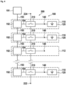
- the battery storage system 100 includes a multilevel converter 200, which further includes a plurality of converter modules 210. These converter modules 210 are electrically connected in series to provide a voltage and a current between a first port 222 and a second port 224. Each output voltage is associated with a storage section 110. Each of the storage sections 110 may contain a battery 120. There may also be empty storage sections which do not contain a battery, like storage section 112 which may be of the same type as the other storage sections 110, but it is not loaded with a battery. The batteries 120 may be connected by electrical connection means 140 to an associated converter module 210. A controller 190 is connected to each of the converter modules 210 and issues control signals to the converter modules 210 via signal lines 194.
- FIG 3 a modified embodiment of a battery storage system 100.
- the converter modules 210 are included into the storage sections 110. This results in a very compact and modular design of the battery storage system. The function remains basically the same as described above.
- each storage section includes a sub-controller 192 which communicate with a master controller 191.
- the sub-controllers 192 may also communicate with each other. Communication may be done via a standard network or bus system.
- any controller e.g. the master controller and/or a sub controller may communicate with a battery management system included in a battery.
- each converter module may have its own housing.
- a storage section may have a separate housing, which may further include a converter module and/or a sub controller.
- a basic converter module 210 is shown in an OFF-state.
- the bypass switch 212 is closed and the battery switch 214 is open, such that the battery is disconnected, such that a bypass current 213 between a first module port 216 and a second module port 217 may flow.
- the current may also flow in an opposite direction as indicated.
- a basic connector module 210 in an ON-state.
- the bypass switch 212 is open and the battery switch 214 is closed, such that the battery 120 is included in the current path and a battery current 215 between a first module port 216 and a second module port 217 may flow through the battery.
- the battery current 215 the battery may be discharged and provide power to an external load.
- the current may also flow in the opposite direction for charging the battery 120 from an external source.
- the converter module must be able to provide an ON-state where a battery is included in the current path, and an OFF-state where the battery is switched OFF, but a current flow is still maintained. This may also be done by other more complex switching topologies which may not include only two switches, but three, four, five, six, or more switches. These more complex topologies often provide a plurality of further ON-states, where for example batteries may be switched in series or anti-series or in parallel to another battery. Generally, in such ON-states there is a power exchange with a battery, which means that the battery is either charged or discharged, whereas in an OFF-state, the converter module behaves passive and simply acts in conducting a current without delivering or consuming power.
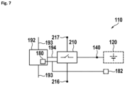
- a storage section 110 is shown in more detail.
- a storage section including a converter module 210 and a sub-controller 192 is shown.
- Each storage section 110 includes a converter module 210 which may have a first module port 216 and a second module port 217 for connection with further converter modules 210 of further storage sections 110.
- the storage section 110 may further provide an electrical connection means 140 configured to connect a battery to the converter module 210.
- the battery is drawn dashed to symbolize that the battery is optional.
- the sub-controller 192 includes a means 180 for detecting the presence of a battery.
- This means may be configured to measure the voltage across the battery or it may detect the presence of the battery by a physical or optical detection.
- a means may be a sensor 182 which may be a mechanical switch, a weight sensor, a light sensor, a temperature sensor, or a voltage or current sensor. It may also receive battery voltage information from the converter module 210.
- a battery module 300 is shown, which may be inserted into a storage section 110.
- the batteries 120 as shown in Figure 1 may be held in a battery module 300 as shown.
- the battery module 300 may include a housing 310, which normally would be comparatively rigid, as it may have to bear a large weight of a number of battery cells.
- the housing may include sliding rails 320 or wheels which may allow sliding of the housing into a storage section 110.
- FIG. 9 a rear view of the housing 310 is shown.
- the rear side of the housing may include a connection panel 330 which may further include electrical connector 335 matching to or being part of the connection means 140 like high current connectors. These connectors may be automatically connected, when the battery module 300 is inserted into a rack with a storage section 110.
- a battery module 300 with an open housing 310 is shown. It may include a plurality of battery cells 340.
- the battery module 300 may further have a locking mechanism 350 which may include an operating handle 351 at the front side of the housing, at least one transfer bar 352, and at least one lock 353 at the rear side of the housing.
- a lock or a pair of locks 353 at the rear side of the housing may be operated and engage with the storage section 110, such that the housing 310 may be securely locked within the storage section 110.
- a switch 360 may be operated by the handle 351, and provides a signal that the handle housing been operated and the battery module has been locked within the storage section 110 to a controller 190, 192. Only when the controller has received a positive signal from the switch, it may switch a converter module associated to the respectively storage section 110 to an ON-state. There may also be switch coupled to the battery module itself, but this specific solution with detecting the state of a lever operating a locking mechanism offers some additional benefits. For removing the module, the locking lever must be operated. The switch is triggered and gives a signal to the controller which disables the battery even before the lever is in the fully unlocked position and before the battery can be pulled out. This allows for a safe shutdown before removing the battery.
- FIG 12 details of a rack including multiple storage sections 110 are shown.
- Nine often storage sections 110 are occupied with battery modules 300. Only one storage section is empty. At the empty storage section, a back panel 400 is shown.
- the back panel 400 includes at least one power connector 410 which may be part of the connection means 140. There may also be a communication connector which may be used for communication between an internal battery module management system and a controller of the battery storage system.
- the back panel 400 may also include a converter module 210.
- a battery storage system is shown in a rear view.
- This battery storage system includes a rack 105 with ten storage sections 110.
- a rack may include any other number of storage sections.
- a battery storage system may also include any other number of storage sections.
- each storage section includes a converter module 210.
- the converter modules 210 may be mounted to the back panels 400. They may be connected by the power connectors 410 as shown in the previous Figures automatically, when a battery is inserted.
- the converter modules 210 are connected by bus bars 430 which provide the connection 216 and 217 between adjacent modules. Further, a communication bus 193 may be provided. This results in a very compact system.
- Figure 15 shows a rack 105 with converter modules 210 in a door 107.
- the converter modules 210 may be arranged close to their corresponding storage sections, which may hold batteries 120.
- the converter modules 210 are easily accessible, simply by opening the door of the rack. Further, the cabling to the batteries is comparatively short.
- the converter modules are moved out of the way from the batteries, such that the batteries can easily be removed or inserted into their storage sections.
- Figure 16 shows a detail of the previous rack.
- the converter modules contain in the same housing a sub controller 192.
- each sub controller may be connected by a communication line 193 to another sub controller or master controller.
- the converter modules may be connected by power cables 230 to batteries 120.
- sub-controllers may be connected by bus cables 232 to batteries 120 such that they may communicate with a battery management system.
- FIG 17 a flow chart of a method of operating a battery storage system including a multilevel converter and a plurality of storage sections is shown. The method starts at step 800.
- step 801 the system is initiated and the number of battery modules is counted.
- step 802 the number of connected modules is checked, and/or it is checked whether a module presence detection has changed, or the number of modules has changed.
- step 803 is performed which integrates the new module in the system. Now the system knows that it has another module. If the number of modules has decreased, it has one module less to use for generation of a requested output voltage and/or output voltage waveform. This step is skipped if the number of modules has not changed.
- step 804 a check of health data of all batteries is done. This is the first step of a cyclic procedure. Based on this, if all modules are in safe state, then step 805 diverts to step 806, otherwise, step 812 follows. In step 806 it is check whether a battery module has to be removed. If there is no battery to be removed, then it is again proceeded to step 804 with a health check of the battery modules. If a battery has to be removed, it is checked in step 807, if the remaining number of active modules is sufficient for the required output voltage or output waveform.
- step 808 diverts to step 809 where the module to be removed is bridged or switched into an OFF-state. The procedure is continued then with step 802 for configuring the number change.
- step 808 If in step 808 it has been decided that the number of active modules is not sufficient, then a system shutdown is performed and an error message is sent to the operator in step 810. The procedure is ended with step 811.
- step 805 If in step 805 it is determined that at least one module is not in a safe state, then the procedure is continued with step 812 and proceeds to step 813 which further proceeds with the health check of state 804. The procedure between steps 812 and 813 is shown in the next Figure.
- Figure 18 shows a further flow diagram of a partial procedure to handle an unsafe state of a module. This starts with step 812 of the previous diagram and proceeds to step 814, where it is determined whether a failure may be hazardous for people and/or environment. If this failure is hazardous, then step 815 makes a system shutdown and sends an alarm message to the operator. The program is ended in step 811.
- step 814 determines that the failure is not hazardous, then the procedure proceeds with step 816 which checks whether an uninterrupted operation mode is active. If this is not active, it continues with step 821 resulting in a system shutdown and sending of an error message to the operator. Finally, the program is terminated in step 811. Step 816 may be omitted such that step 811 follows on step 814.
- step 816 If an uninterrupted operation mode is active in step 816, it is checked whether the remaining numbers of active modules are sufficient for the required output voltage and/or waveform. If it is sufficient, step 818 diverts to step 819 to disable the defective module and continue with step 813 which goes back to the diagram of the previous Figure.
- step 818 If the module number is determined as not sufficient in step 818, it diverts to step 820 resulting in a system shutdown and sending an error message to the operator with finally terminating the program in step 811.
Landscapes
- Engineering & Computer Science (AREA)
- Power Engineering (AREA)
- Chemical & Material Sciences (AREA)
- Chemical Kinetics & Catalysis (AREA)
- Electrochemistry (AREA)
- General Chemical & Material Sciences (AREA)
- Manufacturing & Machinery (AREA)
- Microelectronics & Electronic Packaging (AREA)
- Aviation & Aerospace Engineering (AREA)
- Secondary Cells (AREA)
- Charge And Discharge Circuits For Batteries Or The Like (AREA)
Description
- The present invention relates to an energy storage system based on batteries. It may be based on second-life electrical vehicle batteries.
- There is an increasing market for equipment for reusing used batteries. Thus, batteries which were already used, e.g., in electric vehicles and do no longer have the full capacity may further be used for power-grid stabilization. For this purpose, multiple types of batteries should be usable in a battery storage system. Further, it may be beneficial to allow for easy exchange of the individual batteries, for example if they reach end of life or if they are defective. Further, the battery storage system should be operable with a variable number of batteries and preferably, even if batteries are provided at random storage places.
-
EP 2 704 247 A2 discloses a battery rack with an integrated cooling system. Such a rack may store many batteries and may provide a cooling of the batteries at the same time.US 10,305,298 B2 - The problem to be solved by the invention is to provide a flexible battery storage system which may employ a variable number of batteries, and which can easily be exchanged. Further, it may allow to use different types of batteries which may for example have different battery voltages and/or different capacities. Solutions of the problem are described in the independent claims. The dependent claims relate to further improvements of the invention.
- The invention is set out in the appended set of claims.
- In the following the invention will be described by way of example, without limitation of the general inventive concept, on examples of embodiment with reference to the drawings.
-
Figure 1 shows a battery storage system. -
Figure 2 shows a block diagram of a battery storage system. -
Figure 3 shows a modified embodiment. -
Figure 4 shows another embodiment. -
Figure 5 shows a basic converter module in an OFF-state. -
Figure 6 shows a basic connector module in an ON-state. -
Figure 7 shows a storage section in more detail. -
Figure 8 shows a battery module. -
Figure 9 shows a rear view of the housing. -
Figure 10 shows a battery module with an open housing. -
Figure 11 shows a detail of the locking mechanism. -
Figure 12 shows details of a rack. -
Figure 13 shows a detail of the previous Figure. -
Figure 14 shows a battery storage system in a rear view. -
Figure 15 shows a rack with converter modules in a door. -
Figure 16 shows a detail of the previous rack. -
Figure 17 shows a flow chart of a method of operating a battery storage system. -
Figure 18 shows a further flow diagram of a partial procedure. - In
Figure 1 , abattery storage system 100 is shown. Thebattery storage system 100 may include arack 105 which may further hold a plurality ofstorage sections 110. Here, the storage sections are shown within a rack, but they may be arranged in any different way, for example a storage section may be a position or a container positioned on a building floor or even outdoors. Basically, a storage section provides means for holding at least onebattery 120. - In an embodiment, where a
battery storage system 100 includes arack 105, the converter modules may be arranged in the rear of the rack or at the sides of the rack. This gives a free access to the batteries. Alternatively, the converter modules may be arranged in a front door of the rack. This would give a free access to the batteries when opening the door, and would at the same time provide short and easily accessible cabling to the batteries. Further, the converter modules may be arranged in in a separate module between the front door and the batteries - which then may be held by hinges to allow access to the batteries. - The term "battery" is used in a very broad sense herein. A battery may include a single battery cell, a plurality of battery cells, or a battery module. In most applications, battery modules are used, because they provide a convenient housing for a plurality of battery cells. Often, a battery module includes at least a minimum battery management system which may monitor essential battery characteristics, like output voltage, temperature, current, etc.
- There may be at least one holding means for holding at least one battery. The holding means may have a very general structure, or they may be specifically adapted to a specific type of battery. A very general type of holding means may be a space on a concrete floor. A more specific holding means may be straight slides in a 19 Inch rack, and battery-specific holding means may be specific slides adapted to a specific type of battery module. There may also be wheels or linear bearings for supporting large mechanical loads as being caused by heavy batteries. These may simplify insertionand/or removal of heavy batteries. Such specific holding means may further include a specific plug and/or socket connector to connect a battery when it is inserted into the storage section.
- A
storage section 110 may include at least one electrical connection means 140, which is configured for electrically the at least onebattery 120. Theconnecting means 140 is not shown in this Figure, because it is hidden by other structures. Basically, an electrical connection means may be a wiring, cabling, together with a connector. It may also include current bars or printed circuit boards. Basically, a connector may be any known plug and socket connector, it may also include a screw connector, like cable shoes or a screw connection to a current bar. Basically, the electrical connection means may allow to connect a battery to the battery storage system and to disconnect the battery if required, for example for exchanging the battery. Furthermore, the battery connector system may be configured to connect a single battery or a plurality of batteries within a storage section. For example, a plurality of battery modules or battery cells may be switched in parallel or in series or in any other configuration within a storage section. - As shown in this Figure, not every storage section must be occupied with a battery. In the embodiment shown, ten
storage sections 110 are provided, and only nine of them are occupied by batteries. Generally, the battery storage system will work with any number of batteries above a minimum number of batteries. Batteries may be dynamically inserted into and/or removed from the battery storage system, as long as the required minimum number of batteries is reached. - In
Figure 2 , a block diagram of a battery storage system is shown. Thebattery storage system 100 includes amultilevel converter 200, which further includes a plurality ofconverter modules 210. Theseconverter modules 210 are electrically connected in series to provide a voltage and a current between afirst port 222 and asecond port 224. Each output voltage is associated with astorage section 110. Each of thestorage sections 110 may contain abattery 120. There may also be empty storage sections which do not contain a battery, likestorage section 112 which may be of the same type as theother storage sections 110, but it is not loaded with a battery. Thebatteries 120 may be connected by electrical connection means 140 to an associatedconverter module 210. Acontroller 190 is connected to each of theconverter modules 210 and issues control signals to theconverter modules 210 via signal lines 194. - In
Figure 3 , a modified embodiment of abattery storage system 100. Here, theconverter modules 210 are included into thestorage sections 110. This results in a very compact and modular design of the battery storage system. The function remains basically the same as described above. - In
Figure 4 , another embodiment of abattery storage system 100 is shown. Here, thecontroller 190 is split into a plurality of sub-controllers which are part of the storage sections. Accordingly, each storage section includes a sub-controller 192 which communicate with amaster controller 191. The sub-controllers 192 may also communicate with each other. Communication may be done via a standard network or bus system. - In general, any controller, e.g. the master controller and/or a sub controller may communicate with a battery management system included in a battery.
- Generally, there may be different combinations of devices in one or more commen housings. For example, each converter module may have its own housing. There may also be a sub controller included with a converter module in a common housing. Further a storage section may have a separate housing, which may further include a converter module and/or a sub controller.
- In
Figure 5 , abasic converter module 210 is shown in an OFF-state. Here, thebypass switch 212 is closed and thebattery switch 214 is open, such that the battery is disconnected, such that a bypass current 213 between afirst module port 216 and asecond module port 217 may flow. The current may also flow in an opposite direction as indicated. - In
Figure 6 , abasic connector module 210 in an ON-state. Here, thebypass switch 212 is open and thebattery switch 214 is closed, such that thebattery 120 is included in the current path and a battery current 215 between afirst module port 216 and asecond module port 217 may flow through the battery. In this case, as indicated by the arrow thebattery current 215, the battery may be discharged and provide power to an external load. The current may also flow in the opposite direction for charging thebattery 120 from an external source. - These Figures show only the minimum requirement of a converter module. The converter module must be able to provide an ON-state where a battery is included in the current path, and an OFF-state where the battery is switched OFF, but a current flow is still maintained. This may also be done by other more complex switching topologies which may not include only two switches, but three, four, five, six, or more switches. These more complex topologies often provide a plurality of further ON-states, where for example batteries may be switched in series or anti-series or in parallel to another battery. Generally, in such ON-states there is a power exchange with a battery, which means that the battery is either charged or discharged, whereas in an OFF-state, the converter module behaves passive and simply acts in conducting a current without delivering or consuming power.
- In
Figure 7 , astorage section 110 is shown in more detail. Here, for simplification a storage section including aconverter module 210 and a sub-controller 192 is shown. Basically, the same concept works also with all other embodiments and modifications as shown herein. Eachstorage section 110 includes aconverter module 210 which may have afirst module port 216 and asecond module port 217 for connection withfurther converter modules 210 offurther storage sections 110. There may also be a sub-controller 192 which may communicate bycommunication lines 193 with other sub-controllers and/or a master controller. Thestorage section 110 may further provide an electrical connection means 140 configured to connect a battery to theconverter module 210. Here, the battery is drawn dashed to symbolize that the battery is optional. The sub-controller 192 includes ameans 180 for detecting the presence of a battery. This means may be configured to measure the voltage across the battery or it may detect the presence of the battery by a physical or optical detection. Such a means may be asensor 182 which may be a mechanical switch, a weight sensor, a light sensor, a temperature sensor, or a voltage or current sensor. It may also receive battery voltage information from theconverter module 210. - In
Figure 8 , abattery module 300 is shown, which may be inserted into astorage section 110. Actually, thebatteries 120 as shown inFigure 1 may be held in abattery module 300 as shown. Thebattery module 300 may include ahousing 310, which normally would be comparatively rigid, as it may have to bear a large weight of a number of battery cells. The housing may include slidingrails 320 or wheels which may allow sliding of the housing into astorage section 110. - In
Figure 9 , a rear view of thehousing 310 is shown. The rear side of the housing may include aconnection panel 330 which may further includeelectrical connector 335 matching to or being part of the connection means 140 like high current connectors. These connectors may be automatically connected, when thebattery module 300 is inserted into a rack with astorage section 110. - In
Figure 10 , abattery module 300 with anopen housing 310 is shown. It may include a plurality ofbattery cells 340. Thebattery module 300 may further have alocking mechanism 350 which may include anoperating handle 351 at the front side of the housing, at least onetransfer bar 352, and at least onelock 353 at the rear side of the housing. By operating the handle at the front side of the housing, a lock or a pair oflocks 353 at the rear side of the housing may be operated and engage with thestorage section 110, such that thehousing 310 may be securely locked within thestorage section 110. - In
Figure 11 , a detail of thelocking mechanism 350 is shown. Aswitch 360 may be operated by thehandle 351, and provides a signal that the handle housing been operated and the battery module has been locked within thestorage section 110 to acontroller storage section 110 to an ON-state. There may also be switch coupled to the battery module itself, but this specific solution with detecting the state of a lever operating a locking mechanism offers some additional benefits. For removing the module, the locking lever must be operated. The switch is triggered and gives a signal to the controller which disables the battery even before the lever is in the fully unlocked position and before the battery can be pulled out. This allows for a safe shutdown before removing the battery. - In
Figure 12 , details of a rack includingmultiple storage sections 110 are shown. Nine oftenstorage sections 110 are occupied withbattery modules 300. Only one storage section is empty. At the empty storage section, aback panel 400 is shown. - In
Figure 13 , a detail of the previous Figure is shown. Here, theback panel 400 is enlarged. Theback panel 400 includes at least onepower connector 410 which may be part of the connection means 140. There may also be a communication connector which may be used for communication between an internal battery module management system and a controller of the battery storage system. Theback panel 400 may also include aconverter module 210. - In
Figure 14 , a battery storage system is shown in a rear view. This battery storage system includes arack 105 with tenstorage sections 110. Of course, a rack may include any other number of storage sections. Furthermore, a battery storage system may also include any other number of storage sections. - In this embodiment, each storage section includes a
converter module 210. Here, only some of the converter modules are marked for clarity reasons. Theconverter modules 210 may be mounted to theback panels 400. They may be connected by thepower connectors 410 as shown in the previous Figures automatically, when a battery is inserted. Theconverter modules 210 are connected bybus bars 430 which provide theconnection communication bus 193 may be provided. This results in a very compact system. -
Figure 15 shows arack 105 withconverter modules 210 in adoor 107. Here, theconverter modules 210 may be arranged close to their corresponding storage sections, which may holdbatteries 120. By this way, theconverter modules 210 are easily accessible, simply by opening the door of the rack. Further, the cabling to the batteries is comparatively short. When the door is open, the converter modules are moved out of the way from the batteries, such that the batteries can easily be removed or inserted into their storage sections. -
Figure 16 shows a detail of the previous rack. In this embodiment, the converter modules contain in the same housing asub controller 192. Here, each sub controller may be connected by acommunication line 193 to another sub controller or master controller. The converter modules may be connected bypower cables 230 tobatteries 120. Further, sub-controllers may be connected bybus cables 232 tobatteries 120 such that they may communicate with a battery management system. - In
Figure 17 , a flow chart of a method of operating a battery storage system including a multilevel converter and a plurality of storage sections is shown. The method starts atstep 800. - In
step 801, the system is initiated and the number of battery modules is counted. - In
step 802, the number of connected modules is checked, and/or it is checked whether a module presence detection has changed, or the number of modules has changed. - If the number of modules has changed, then step 803 is performed which integrates the new module in the system. Now the system knows that it has another module. If the number of modules has decreased, it has one module less to use for generation of a requested output voltage and/or output voltage waveform. This step is skipped if the number of modules has not changed.
- In
step 804, a check of health data of all batteries is done. This is the first step of a cyclic procedure. Based on this, if all modules are in safe state, then step 805 diverts to step 806, otherwise,step 812 follows. Instep 806 it is check whether a battery module has to be removed. If there is no battery to be removed, then it is again proceeded to step 804 with a health check of the battery modules. If a battery has to be removed, it is checked instep 807, if the remaining number of active modules is sufficient for the required output voltage or output waveform. - If it is sufficient, then step 808 diverts to step 809 where the module to be removed is bridged or switched into an OFF-state. The procedure is continued then with
step 802 for configuring the number change. - If in
step 808 it has been decided that the number of active modules is not sufficient, then a system shutdown is performed and an error message is sent to the operator instep 810. The procedure is ended withstep 811. - If in
step 805 it is determined that at least one module is not in a safe state, then the procedure is continued withstep 812 and proceeds to step 813 which further proceeds with the health check ofstate 804. The procedure betweensteps -
Figure 18 shows a further flow diagram of a partial procedure to handle an unsafe state of a module. This starts withstep 812 of the previous diagram and proceeds to step 814, where it is determined whether a failure may be hazardous for people and/or environment. If this failure is hazardous, then step 815 makes a system shutdown and sends an alarm message to the operator. The program is ended instep 811. - If
step 814 determines that the failure is not hazardous, then the procedure proceeds withstep 816 which checks whether an uninterrupted operation mode is active. If this is not active, it continues withstep 821 resulting in a system shutdown and sending of an error message to the operator. Finally, the program is terminated instep 811. Step 816 may be omitted such thatstep 811 follows onstep 814. - If an uninterrupted operation mode is active in
step 816, it is checked whether the remaining numbers of active modules are sufficient for the required output voltage and/or waveform. If it is sufficient,step 818 diverts to step 819 to disable the defective module and continue withstep 813 which goes back to the diagram of the previous Figure. - If the module number is determined as not sufficient in
step 818, it diverts to step 820 resulting in a system shutdown and sending an error message to the operator with finally terminating the program instep 811. -
- 100
- battery storage system
- 105
- rack
- 107
- door
- 110
- storage section
- 120
- battery
- 130
- holding means
- 140
- electrical connection means
- 180
- means for detecting the presence of a battery
- 190
- controller
- 191
- master controller
- 192
- sub controller
- 193
- communication lines
- 200
- multilevel converter
- 210
- converter module
- 212
- bypass switch
- 213
- bypass current
- 214
- battery switch
- 215
- battery current
- 216
- first module port
- 217
- second module port
- 222
- first port
- 224
- second port
- 230
- power cables
- 232
- bus cables
- 300
- battery module
- 310
- housing
- 320
- slide rails
- 330
- connection panel
- 335
- connector
- 340
- battery cells
- 350
- locking mechanism
- 351
- handle
- 352
- transfer bar
- 353
- lock
- 400
- backplane
- 410
- power connector
- 420
- communication connector
- 430
- bus bar
- 800 - 821
- flow diagram steps
Claims (15)
- Battery storage system (100) including a multilevel-converter (200)wherein the multilevel-converter (200) comprises a plurality of converter modules (210) being connected in series with each other and,each of the converter modules (210) comprising at least one bypass switch (212) configured to bypass the at least one battery (120), and at least a battery switch (214) configured to disconnect the at least one battery (120) at the same time when the bypass switch (212) bypasses the at least one battery (120),characterized in, thatthe battery storage system (100) is further including a plurality of storage sections (110), each storage section (110) comprises- at least one holding means (130) configured for holding at least one battery (120) and- at least one electrical connection means (140) configured for electrically connecting the at least one battery (120),and at least one of the converter modules (210) being associated with at least one of the storage sections (110),the battery storage system (100) further comprising a controller (190) which has means (180) for detecting the presence of at least one battery in each storage section (110) and means (194) for configuring the switches (212, 214) of the plurality of converter modules (210) based on the presence of batteries such that the plurality of converter modules (210) provides a required voltage.
- Battery storage system according to claim 1,
characterized in, that
each converter module (210) has at least:an ON state, where the bypass switch (212) is open, and the battery switch (214) is closed andan OFF state where the bypass switch (212) is closed to bypass the at least one battery (120), and the battery switch (214) is open. - Battery storage system according to any of the previous claims, characterized in, that
the controller (190) is configured to switch a converter module (210) to an OFF state if at the associated storage section (110) no presence of at least one battery was detected. - Battery storage system according to any of the previous claims, characterized in, that
the means (180) for detecting the presence of a battery (120) is configured to detect an electrical connection between a battery (120) and a converter module (210). - Battery storage system (100) according to any of the previous claims, characterized in, that
at least one storage section (110) has at least one means (180) for detecting the presence of a battery including at least one of:- a voltage measurement means configured to measure a battery voltage,- a weight detection means configured to detect a battery mass,- a volume detection means configured to detect a battery volume,- an optical detection means configured to detect a battery appearance or marking. - Battery storage system according to any of the previous claims, characterized in, that
the controller (190) is configured to communicate with at least one battery management system included in the at least one battery (120). - Battery storage system according to the previous claim,
characterized in, that
the controller (190) is configured to communicate battery health data and/or battery operation data with the at least one battery management system. - Battery storage system according to any of the previous claims, characterized in, that
a communication connector is provided in at least one of the storage sections, wherein the communication connector may be used for communication between an internal battery module management system of a battery and the controller (190). - Battery storage system (100) according to any of the previous claims, characterized in, that
at least one storage section (110) includes at least one of a means for fixing a battery to the storage section and/or a tray for holding a battery. - Battery storage system (100) according to any of the previous claims, characterized in, that
the at least one electrical connection means (140) comprises at least one of a cable with at least one connector, a current bar, and a printed circuit board. - Battery storage system (100) according to any of the previous claims, characterized in, that
a plurality of storage sections (110) are held by a rack (105) and the plurality of associated converter modules (210) is held within a door of the rack. - A method of operating a battery storage system (100) including:a multilevel-converter (200) including a plurality of converter modules (210) anda plurality of storage sections (110) configured for holding at least one battery (120), the method comprising the steps of:a) assigning at least one converter modules (210) to at least one storage section,b) switching all multilevel converters to an OFF state,c) identifying storage sections occupied with at least one battery,d) getting battery data including at least a battery voltage of storage sections having a battery,e) checking whether the total voltage of all storage sections with at least one battery exceeds a required minimum output voltage,f) then starting with multilevel converter operation,g) else stopping or go to any of steps a-c.
- A method of operating a battery storage system (100) according to claim 12, the method comprises after starting with multilevel converter operation in step f) periodically continuing from step c) during multilevel converter operation.
- A method of operating a battery storage system (100) according to claim 12 or 13, includes further the steps ofquerying periodically and/or checking at least one means (180) for detecting the presence of at least one battery in a storage section, andif a status of a storage section changes from present to absent, immediately setting the converter module of that storage section to an OFF state.
- A method of operating a battery storage system (100) according to any of claims 12 or 14, includes further the steps ofquerying periodically and/or checking at least one operating parameter including at least one of a state of health, a state of charge, a voltage, and a current, andif at least one of the operating parameters falls out of predetermined limits, setting the converter module of that storage section to an OFF state.
Applications Claiming Priority (2)
| Application Number | Priority Date | Filing Date | Title |
|---|---|---|---|
| DE102020003060 | 2020-05-23 | ||
| PCT/EP2021/063665 WO2021239620A1 (en) | 2020-05-23 | 2021-05-21 | Modular battery storage system |
Publications (3)
| Publication Number | Publication Date |
|---|---|
| EP4154375A1 EP4154375A1 (en) | 2023-03-29 |
| EP4154375C0 EP4154375C0 (en) | 2024-05-08 |
| EP4154375B1 true EP4154375B1 (en) | 2024-05-08 |
Family
ID=76098960
Family Applications (1)
| Application Number | Title | Priority Date | Filing Date |
|---|---|---|---|
| EP21727864.7A Active EP4154375B1 (en) | 2020-05-23 | 2021-05-21 | Modular battery storage system |
Country Status (4)
| Country | Link |
|---|---|
| US (1) | US12587022B2 (en) |
| EP (1) | EP4154375B1 (en) |
| CN (1) | CN115702534A (en) |
| WO (1) | WO2021239620A1 (en) |
Families Citing this family (8)
| Publication number | Priority date | Publication date | Assignee | Title |
|---|---|---|---|---|
| EP3790148A1 (en) * | 2019-09-03 | 2021-03-10 | Universität der Bundeswehr München | Charging system for electric vehicles |
| KR102486708B1 (en) * | 2020-09-16 | 2023-01-10 | 엘에스일렉트릭(주) | Temperature measuring device and energy storage system having the same |
| CA3170801A1 (en) * | 2021-08-19 | 2023-02-19 | Neutron Automotive Controls Inc. | Battery cell balancing circuit system and method |
| EP4270705A1 (en) | 2022-04-26 | 2023-11-01 | General Electric Technology GmbH | Dc energy storage system |
| EP4270706A1 (en) | 2022-04-26 | 2023-11-01 | General Electric Technology GmbH | Dc energy storage system |
| US12580264B2 (en) * | 2022-11-18 | 2026-03-17 | Moment Energy Inc. | Battery tray |
| EP4415206A1 (en) * | 2023-02-09 | 2024-08-14 | Hitachi Energy Ltd | An energy storage segment for an energy storage system and a method for controlling an energy storage system |
| KR102834942B1 (en) * | 2023-08-10 | 2025-07-15 | 신동훈 | Energy storage device using used batteries |
Citations (2)
| Publication number | Priority date | Publication date | Assignee | Title |
|---|---|---|---|---|
| JP2016517258A (en) * | 2013-03-15 | 2016-06-09 | デザイン フラックス テクノロジーズ, エルエルシーDesign Flux Technologies, Llc | Method and apparatus for creating a dynamically reconfigurable energy storage device |
| EP2704247B1 (en) * | 2011-05-31 | 2016-09-28 | LG Chem, Ltd. | Battery cooling system and battery rack applied thereto |
Family Cites Families (10)
| Publication number | Priority date | Publication date | Assignee | Title |
|---|---|---|---|---|
| HK1045076A2 (en) * | 2001-09-03 | 2002-11-01 | 金柏电子国际有限公司 | An intelligent serial battery charger and charging block |
| JP5466586B2 (en) * | 2009-10-05 | 2014-04-09 | プライムアースEvエナジー株式会社 | Battery management device |
| EP2517327B1 (en) * | 2009-12-22 | 2013-06-12 | ABB Research LTD | Battery energy storage system with short circuit protection, and method |
| JP5618359B2 (en) * | 2010-08-02 | 2014-11-05 | Necエナジーデバイス株式会社 | Secondary battery pack connection control method and power storage system |
| KR101245279B1 (en) * | 2010-10-11 | 2013-03-19 | 주식회사 엘지화학 | Method and System for setting up sequent ID of multi-slave in battery pack |
| WO2012158185A1 (en) * | 2011-05-13 | 2012-11-22 | Enerdel, Inc. | Energy storage system |
| US9537328B2 (en) * | 2013-05-23 | 2017-01-03 | Samsung Sdi Co., Ltd. | Battery management system and method of driving the same |
| US10305298B2 (en) * | 2014-03-17 | 2019-05-28 | Glx Power Systems, Inc. | Method and apparatus for creating a dynamically reconfigurable energy storage device |
| CN205248399U (en) * | 2015-09-25 | 2016-05-18 | 健格科技股份有限公司 | Energy storage battery supply system with field replaceable battery modules |
| GB2569947A (en) * | 2017-12-28 | 2019-07-10 | Moog Unna Gmbh | Power supply arrangement with by-pass diodes |
-
2021
- 2021-05-21 WO PCT/EP2021/063665 patent/WO2021239620A1/en not_active Ceased
- 2021-05-21 CN CN202180037260.4A patent/CN115702534A/en active Pending
- 2021-05-21 EP EP21727864.7A patent/EP4154375B1/en active Active
-
2022
- 2022-11-14 US US17/986,476 patent/US12587022B2/en active Active
Patent Citations (2)
| Publication number | Priority date | Publication date | Assignee | Title |
|---|---|---|---|---|
| EP2704247B1 (en) * | 2011-05-31 | 2016-09-28 | LG Chem, Ltd. | Battery cooling system and battery rack applied thereto |
| JP2016517258A (en) * | 2013-03-15 | 2016-06-09 | デザイン フラックス テクノロジーズ, エルエルシーDesign Flux Technologies, Llc | Method and apparatus for creating a dynamically reconfigurable energy storage device |
Also Published As
| Publication number | Publication date |
|---|---|
| US12587022B2 (en) | 2026-03-24 |
| US20230071601A1 (en) | 2023-03-09 |
| EP4154375C0 (en) | 2024-05-08 |
| EP4154375A1 (en) | 2023-03-29 |
| CN115702534A (en) | 2023-02-14 |
| WO2021239620A1 (en) | 2021-12-02 |
Similar Documents
| Publication | Publication Date | Title |
|---|---|---|
| EP4154375B1 (en) | Modular battery storage system | |
| EP2587565B1 (en) | Secondary battery unit | |
| US9661777B2 (en) | Systems and methods for coupling AC power to a rack-level power infrastructure | |
| EP1462813B1 (en) | Electrical cabinet for configuring an Uninterruptible Power System and back panel for use therein | |
| CA2523240C (en) | Universal battery module and controller therefor | |
| US9281717B2 (en) | Form factor swappable DC battery back-up | |
| JP5675951B2 (en) | Power storage system with battery | |
| EP3893289B1 (en) | Energy storage system | |
| CN110998898A (en) | A modularization lithium ion battery system for fork truck | |
| US20040168818A1 (en) | System for detecting defective battery packs | |
| JP6289803B2 (en) | Storage battery device, storage battery device management method, and storage battery system | |
| US20250226675A1 (en) | Energy storage system and protection unit | |
| CN113595165A (en) | Battery spare unit frame, battery management system and electronic rack | |
| EP3014726B1 (en) | Energy storage system | |
| EP3166201B1 (en) | Uninterruptible power supply system with good serviceability | |
| WO2021096043A1 (en) | Module battery system | |
| CN100477335C (en) | Battery and assembled rack battery system | |
| US8730654B2 (en) | Uninterruptible power supply module unit and uninterruptible power supply including the same | |
| CN215813255U (en) | A portable energy storage device detection device | |
| CN216649294U (en) | Lithium battery system of data center and data center | |
| KR20240040012A (en) | Energy storage system having hierarchical structure and operating method thereof | |
| CN211062135U (en) | Storing cabinet | |
| JP2023068394A (en) | Operation method of module transport box and module transport box | |
| KR20260045248A (en) | Battery system and operating method thereof | |
| KR20260043163A (en) | Signal output device and battery system including the same |
Legal Events
| Date | Code | Title | Description |
|---|---|---|---|
| STAA | Information on the status of an ep patent application or granted ep patent |
Free format text: STATUS: UNKNOWN |
|
| STAA | Information on the status of an ep patent application or granted ep patent |
Free format text: STATUS: THE INTERNATIONAL PUBLICATION HAS BEEN MADE |
|
| PUAI | Public reference made under article 153(3) epc to a published international application that has entered the european phase |
Free format text: ORIGINAL CODE: 0009012 |
|
| STAA | Information on the status of an ep patent application or granted ep patent |
Free format text: STATUS: REQUEST FOR EXAMINATION WAS MADE |
|
| 17P | Request for examination filed |
Effective date: 20221129 |
|
| AK | Designated contracting states |
Kind code of ref document: A1 Designated state(s): AL AT BE BG CH CY CZ DE DK EE ES FI FR GB GR HR HU IE IS IT LI LT LU LV MC MK MT NL NO PL PT RO RS SE SI SK SM TR |
|
| DAV | Request for validation of the european patent (deleted) | ||
| DAX | Request for extension of the european patent (deleted) | ||
| GRAP | Despatch of communication of intention to grant a patent |
Free format text: ORIGINAL CODE: EPIDOSNIGR1 |
|
| STAA | Information on the status of an ep patent application or granted ep patent |
Free format text: STATUS: GRANT OF PATENT IS INTENDED |
|
| INTG | Intention to grant announced |
Effective date: 20240207 |
|
| GRAS | Grant fee paid |
Free format text: ORIGINAL CODE: EPIDOSNIGR3 |
|
| GRAA | (expected) grant |
Free format text: ORIGINAL CODE: 0009210 |
|
| STAA | Information on the status of an ep patent application or granted ep patent |
Free format text: STATUS: THE PATENT HAS BEEN GRANTED |
|
| AK | Designated contracting states |
Kind code of ref document: B1 Designated state(s): AL AT BE BG CH CY CZ DE DK EE ES FI FR GB GR HR HU IE IS IT LI LT LU LV MC MK MT NL NO PL PT RO RS SE SI SK SM TR |
|
| RAP3 | Party data changed (applicant data changed or rights of an application transferred) |
Owner name: STABL ENERGY GMBH |
|
| REG | Reference to a national code |
Ref country code: GB Ref legal event code: FG4D |
|
| REG | Reference to a national code |
Ref country code: CH Ref legal event code: EP |
|
| REG | Reference to a national code |
Ref country code: DE Ref legal event code: R096 Ref document number: 602021013098 Country of ref document: DE |
|
| REG | Reference to a national code |
Ref country code: IE Ref legal event code: FG4D |
|
| U01 | Request for unitary effect filed |
Effective date: 20240605 |
|
| U07 | Unitary effect registered |
Designated state(s): AT BE BG DE DK EE FI FR IT LT LU LV MT NL PT SE SI Effective date: 20240620 |
|
| U20 | Renewal fee for the european patent with unitary effect paid |
Year of fee payment: 4 Effective date: 20240621 |
|
| PG25 | Lapsed in a contracting state [announced via postgrant information from national office to epo] |
Ref country code: IS Free format text: LAPSE BECAUSE OF FAILURE TO SUBMIT A TRANSLATION OF THE DESCRIPTION OR TO PAY THE FEE WITHIN THE PRESCRIBED TIME-LIMIT Effective date: 20240908 |
|
| PG25 | Lapsed in a contracting state [announced via postgrant information from national office to epo] |
Ref country code: HR Free format text: LAPSE BECAUSE OF FAILURE TO SUBMIT A TRANSLATION OF THE DESCRIPTION OR TO PAY THE FEE WITHIN THE PRESCRIBED TIME-LIMIT Effective date: 20240508 |
|
| PG25 | Lapsed in a contracting state [announced via postgrant information from national office to epo] |
Ref country code: GR Free format text: LAPSE BECAUSE OF FAILURE TO SUBMIT A TRANSLATION OF THE DESCRIPTION OR TO PAY THE FEE WITHIN THE PRESCRIBED TIME-LIMIT Effective date: 20240809 |
|
| PG25 | Lapsed in a contracting state [announced via postgrant information from national office to epo] |
Ref country code: ES Free format text: LAPSE BECAUSE OF FAILURE TO SUBMIT A TRANSLATION OF THE DESCRIPTION OR TO PAY THE FEE WITHIN THE PRESCRIBED TIME-LIMIT Effective date: 20240508 |
|
| PG25 | Lapsed in a contracting state [announced via postgrant information from national office to epo] |
Ref country code: PL Free format text: LAPSE BECAUSE OF FAILURE TO SUBMIT A TRANSLATION OF THE DESCRIPTION OR TO PAY THE FEE WITHIN THE PRESCRIBED TIME-LIMIT Effective date: 20240508 |
|
| PG25 | Lapsed in a contracting state [announced via postgrant information from national office to epo] |
Ref country code: PL Free format text: LAPSE BECAUSE OF FAILURE TO SUBMIT A TRANSLATION OF THE DESCRIPTION OR TO PAY THE FEE WITHIN THE PRESCRIBED TIME-LIMIT Effective date: 20240508 Ref country code: NO Free format text: LAPSE BECAUSE OF FAILURE TO SUBMIT A TRANSLATION OF THE DESCRIPTION OR TO PAY THE FEE WITHIN THE PRESCRIBED TIME-LIMIT Effective date: 20240808 Ref country code: IS Free format text: LAPSE BECAUSE OF FAILURE TO SUBMIT A TRANSLATION OF THE DESCRIPTION OR TO PAY THE FEE WITHIN THE PRESCRIBED TIME-LIMIT Effective date: 20240908 Ref country code: HR Free format text: LAPSE BECAUSE OF FAILURE TO SUBMIT A TRANSLATION OF THE DESCRIPTION OR TO PAY THE FEE WITHIN THE PRESCRIBED TIME-LIMIT Effective date: 20240508 Ref country code: GR Free format text: LAPSE BECAUSE OF FAILURE TO SUBMIT A TRANSLATION OF THE DESCRIPTION OR TO PAY THE FEE WITHIN THE PRESCRIBED TIME-LIMIT Effective date: 20240809 Ref country code: ES Free format text: LAPSE BECAUSE OF FAILURE TO SUBMIT A TRANSLATION OF THE DESCRIPTION OR TO PAY THE FEE WITHIN THE PRESCRIBED TIME-LIMIT Effective date: 20240508 Ref country code: RS Free format text: LAPSE BECAUSE OF FAILURE TO SUBMIT A TRANSLATION OF THE DESCRIPTION OR TO PAY THE FEE WITHIN THE PRESCRIBED TIME-LIMIT Effective date: 20240808 |
|
| REG | Reference to a national code |
Ref country code: CH Ref legal event code: PL |
|
| PG25 | Lapsed in a contracting state [announced via postgrant information from national office to epo] |
Ref country code: CZ Free format text: LAPSE BECAUSE OF FAILURE TO SUBMIT A TRANSLATION OF THE DESCRIPTION OR TO PAY THE FEE WITHIN THE PRESCRIBED TIME-LIMIT Effective date: 20240508 |
|
| PG25 | Lapsed in a contracting state [announced via postgrant information from national office to epo] |
Ref country code: SK Free format text: LAPSE BECAUSE OF FAILURE TO SUBMIT A TRANSLATION OF THE DESCRIPTION OR TO PAY THE FEE WITHIN THE PRESCRIBED TIME-LIMIT Effective date: 20240508 Ref country code: RO Free format text: LAPSE BECAUSE OF FAILURE TO SUBMIT A TRANSLATION OF THE DESCRIPTION OR TO PAY THE FEE WITHIN THE PRESCRIBED TIME-LIMIT Effective date: 20240508 |
|
| PG25 | Lapsed in a contracting state [announced via postgrant information from national office to epo] |
Ref country code: SM Free format text: LAPSE BECAUSE OF FAILURE TO SUBMIT A TRANSLATION OF THE DESCRIPTION OR TO PAY THE FEE WITHIN THE PRESCRIBED TIME-LIMIT Effective date: 20240508 |
|
| PG25 | Lapsed in a contracting state [announced via postgrant information from national office to epo] |
Ref country code: SM Free format text: LAPSE BECAUSE OF FAILURE TO SUBMIT A TRANSLATION OF THE DESCRIPTION OR TO PAY THE FEE WITHIN THE PRESCRIBED TIME-LIMIT Effective date: 20240508 Ref country code: SK Free format text: LAPSE BECAUSE OF FAILURE TO SUBMIT A TRANSLATION OF THE DESCRIPTION OR TO PAY THE FEE WITHIN THE PRESCRIBED TIME-LIMIT Effective date: 20240508 Ref country code: RO Free format text: LAPSE BECAUSE OF FAILURE TO SUBMIT A TRANSLATION OF THE DESCRIPTION OR TO PAY THE FEE WITHIN THE PRESCRIBED TIME-LIMIT Effective date: 20240508 Ref country code: CZ Free format text: LAPSE BECAUSE OF FAILURE TO SUBMIT A TRANSLATION OF THE DESCRIPTION OR TO PAY THE FEE WITHIN THE PRESCRIBED TIME-LIMIT Effective date: 20240508 Ref country code: CH Free format text: LAPSE BECAUSE OF NON-PAYMENT OF DUE FEES Effective date: 20240531 |
|
| PG25 | Lapsed in a contracting state [announced via postgrant information from national office to epo] |
Ref country code: MC Free format text: LAPSE BECAUSE OF FAILURE TO SUBMIT A TRANSLATION OF THE DESCRIPTION OR TO PAY THE FEE WITHIN THE PRESCRIBED TIME-LIMIT Effective date: 20240508 |
|
| REG | Reference to a national code |
Ref country code: DE Ref legal event code: R097 Ref document number: 602021013098 Country of ref document: DE |
|
| PLBE | No opposition filed within time limit |
Free format text: ORIGINAL CODE: 0009261 |
|
| STAA | Information on the status of an ep patent application or granted ep patent |
Free format text: STATUS: NO OPPOSITION FILED WITHIN TIME LIMIT |
|
| 26N | No opposition filed |
Effective date: 20250211 |
|
| PG25 | Lapsed in a contracting state [announced via postgrant information from national office to epo] |
Ref country code: IE Free format text: LAPSE BECAUSE OF NON-PAYMENT OF DUE FEES Effective date: 20240521 |
|
| U20 | Renewal fee for the european patent with unitary effect paid |
Year of fee payment: 5 Effective date: 20250515 |
|
| PG25 | Lapsed in a contracting state [announced via postgrant information from national office to epo] |
Ref country code: CY Free format text: LAPSE BECAUSE OF FAILURE TO SUBMIT A TRANSLATION OF THE DESCRIPTION OR TO PAY THE FEE WITHIN THE PRESCRIBED TIME-LIMIT; INVALID AB INITIO Effective date: 20210521 |
|
| PG25 | Lapsed in a contracting state [announced via postgrant information from national office to epo] |
Ref country code: HU Free format text: LAPSE BECAUSE OF FAILURE TO SUBMIT A TRANSLATION OF THE DESCRIPTION OR TO PAY THE FEE WITHIN THE PRESCRIBED TIME-LIMIT; INVALID AB INITIO Effective date: 20210521 |
|
| GBPC | Gb: european patent ceased through non-payment of renewal fee |
Effective date: 20250521 |
|
| PG25 | Lapsed in a contracting state [announced via postgrant information from national office to epo] |
Ref country code: GB Free format text: LAPSE BECAUSE OF NON-PAYMENT OF DUE FEES Effective date: 20250521 |
|
| U20 | Renewal fee for the european patent with unitary effect paid |
Year of fee payment: 6 Effective date: 20260323 |