EP3790148A1 - Charging system for electric vehicles - Google Patents
Charging system for electric vehicles Download PDFInfo
- Publication number
- EP3790148A1 EP3790148A1 EP19195179.7A EP19195179A EP3790148A1 EP 3790148 A1 EP3790148 A1 EP 3790148A1 EP 19195179 A EP19195179 A EP 19195179A EP 3790148 A1 EP3790148 A1 EP 3790148A1
- Authority
- EP
- European Patent Office
- Prior art keywords
- mesdcs
- charging
- lpj
- voltage
- control system
- Prior art date
- Legal status (The legal status is an assumption and is not a legal conclusion. Google has not performed a legal analysis and makes no representation as to the accuracy of the status listed.)
- Withdrawn
Links
Images


Classifications
-
- H—ELECTRICITY
- H02—GENERATION; CONVERSION OR DISTRIBUTION OF ELECTRIC POWER
- H02J—CIRCUIT ARRANGEMENTS OR SYSTEMS FOR SUPPLYING OR DISTRIBUTING ELECTRIC POWER; SYSTEMS FOR STORING ELECTRIC ENERGY
- H02J7/00—Circuit arrangements for charging or depolarising batteries or for supplying loads from batteries
- H02J7/0013—Circuit arrangements for charging or depolarising batteries or for supplying loads from batteries acting upon several batteries simultaneously or sequentially
-
- B—PERFORMING OPERATIONS; TRANSPORTING
- B60—VEHICLES IN GENERAL
- B60L—PROPULSION OF ELECTRICALLY-PROPELLED VEHICLES; SUPPLYING ELECTRIC POWER FOR AUXILIARY EQUIPMENT OF ELECTRICALLY-PROPELLED VEHICLES; ELECTRODYNAMIC BRAKE SYSTEMS FOR VEHICLES IN GENERAL; MAGNETIC SUSPENSION OR LEVITATION FOR VEHICLES; MONITORING OPERATING VARIABLES OF ELECTRICALLY-PROPELLED VEHICLES; ELECTRIC SAFETY DEVICES FOR ELECTRICALLY-PROPELLED VEHICLES
- B60L53/00—Methods of charging batteries, specially adapted for electric vehicles; Charging stations or on-board charging equipment therefor; Exchange of energy storage elements in electric vehicles
- B60L53/10—Methods of charging batteries, specially adapted for electric vehicles; Charging stations or on-board charging equipment therefor; Exchange of energy storage elements in electric vehicles characterised by the energy transfer between the charging station and the vehicle
- B60L53/11—DC charging controlled by the charging station, e.g. mode 4
-
- B—PERFORMING OPERATIONS; TRANSPORTING
- B60—VEHICLES IN GENERAL
- B60L—PROPULSION OF ELECTRICALLY-PROPELLED VEHICLES; SUPPLYING ELECTRIC POWER FOR AUXILIARY EQUIPMENT OF ELECTRICALLY-PROPELLED VEHICLES; ELECTRODYNAMIC BRAKE SYSTEMS FOR VEHICLES IN GENERAL; MAGNETIC SUSPENSION OR LEVITATION FOR VEHICLES; MONITORING OPERATING VARIABLES OF ELECTRICALLY-PROPELLED VEHICLES; ELECTRIC SAFETY DEVICES FOR ELECTRICALLY-PROPELLED VEHICLES
- B60L53/00—Methods of charging batteries, specially adapted for electric vehicles; Charging stations or on-board charging equipment therefor; Exchange of energy storage elements in electric vehicles
- B60L53/50—Charging stations characterised by energy-storage or power-generation means
- B60L53/53—Batteries
-
- B—PERFORMING OPERATIONS; TRANSPORTING
- B60—VEHICLES IN GENERAL
- B60L—PROPULSION OF ELECTRICALLY-PROPELLED VEHICLES; SUPPLYING ELECTRIC POWER FOR AUXILIARY EQUIPMENT OF ELECTRICALLY-PROPELLED VEHICLES; ELECTRODYNAMIC BRAKE SYSTEMS FOR VEHICLES IN GENERAL; MAGNETIC SUSPENSION OR LEVITATION FOR VEHICLES; MONITORING OPERATING VARIABLES OF ELECTRICALLY-PROPELLED VEHICLES; ELECTRIC SAFETY DEVICES FOR ELECTRICALLY-PROPELLED VEHICLES
- B60L53/00—Methods of charging batteries, specially adapted for electric vehicles; Charging stations or on-board charging equipment therefor; Exchange of energy storage elements in electric vehicles
- B60L53/60—Monitoring or controlling charging stations
- B60L53/63—Monitoring or controlling charging stations in response to network capacity
-
- B—PERFORMING OPERATIONS; TRANSPORTING
- B60—VEHICLES IN GENERAL
- B60L—PROPULSION OF ELECTRICALLY-PROPELLED VEHICLES; SUPPLYING ELECTRIC POWER FOR AUXILIARY EQUIPMENT OF ELECTRICALLY-PROPELLED VEHICLES; ELECTRODYNAMIC BRAKE SYSTEMS FOR VEHICLES IN GENERAL; MAGNETIC SUSPENSION OR LEVITATION FOR VEHICLES; MONITORING OPERATING VARIABLES OF ELECTRICALLY-PROPELLED VEHICLES; ELECTRIC SAFETY DEVICES FOR ELECTRICALLY-PROPELLED VEHICLES
- B60L53/00—Methods of charging batteries, specially adapted for electric vehicles; Charging stations or on-board charging equipment therefor; Exchange of energy storage elements in electric vehicles
- B60L53/60—Monitoring or controlling charging stations
- B60L53/64—Optimising energy costs, e.g. responding to electricity rates
-
- B—PERFORMING OPERATIONS; TRANSPORTING
- B60—VEHICLES IN GENERAL
- B60L—PROPULSION OF ELECTRICALLY-PROPELLED VEHICLES; SUPPLYING ELECTRIC POWER FOR AUXILIARY EQUIPMENT OF ELECTRICALLY-PROPELLED VEHICLES; ELECTRODYNAMIC BRAKE SYSTEMS FOR VEHICLES IN GENERAL; MAGNETIC SUSPENSION OR LEVITATION FOR VEHICLES; MONITORING OPERATING VARIABLES OF ELECTRICALLY-PROPELLED VEHICLES; ELECTRIC SAFETY DEVICES FOR ELECTRICALLY-PROPELLED VEHICLES
- B60L53/00—Methods of charging batteries, specially adapted for electric vehicles; Charging stations or on-board charging equipment therefor; Exchange of energy storage elements in electric vehicles
- B60L53/60—Monitoring or controlling charging stations
- B60L53/67—Controlling two or more charging stations
-
- B—PERFORMING OPERATIONS; TRANSPORTING
- B60—VEHICLES IN GENERAL
- B60L—PROPULSION OF ELECTRICALLY-PROPELLED VEHICLES; SUPPLYING ELECTRIC POWER FOR AUXILIARY EQUIPMENT OF ELECTRICALLY-PROPELLED VEHICLES; ELECTRODYNAMIC BRAKE SYSTEMS FOR VEHICLES IN GENERAL; MAGNETIC SUSPENSION OR LEVITATION FOR VEHICLES; MONITORING OPERATING VARIABLES OF ELECTRICALLY-PROPELLED VEHICLES; ELECTRIC SAFETY DEVICES FOR ELECTRICALLY-PROPELLED VEHICLES
- B60L58/00—Methods or circuit arrangements for monitoring or controlling batteries or fuel cells, specially adapted for electric vehicles
- B60L58/10—Methods or circuit arrangements for monitoring or controlling batteries or fuel cells, specially adapted for electric vehicles for monitoring or controlling batteries
- B60L58/12—Methods or circuit arrangements for monitoring or controlling batteries or fuel cells, specially adapted for electric vehicles for monitoring or controlling batteries responding to state of charge [SoC]
-
- H—ELECTRICITY
- H02—GENERATION; CONVERSION OR DISTRIBUTION OF ELECTRIC POWER
- H02J—CIRCUIT ARRANGEMENTS OR SYSTEMS FOR SUPPLYING OR DISTRIBUTING ELECTRIC POWER; SYSTEMS FOR STORING ELECTRIC ENERGY
- H02J7/00—Circuit arrangements for charging or depolarising batteries or for supplying loads from batteries
- H02J7/0013—Circuit arrangements for charging or depolarising batteries or for supplying loads from batteries acting upon several batteries simultaneously or sequentially
- H02J7/0014—Circuits for equalisation of charge between batteries
- H02J7/0019—Circuits for equalisation of charge between batteries using switched or multiplexed charge circuits
-
- H—ELECTRICITY
- H02—GENERATION; CONVERSION OR DISTRIBUTION OF ELECTRIC POWER
- H02J—CIRCUIT ARRANGEMENTS OR SYSTEMS FOR SUPPLYING OR DISTRIBUTING ELECTRIC POWER; SYSTEMS FOR STORING ELECTRIC ENERGY
- H02J7/00—Circuit arrangements for charging or depolarising batteries or for supplying loads from batteries
- H02J7/0013—Circuit arrangements for charging or depolarising batteries or for supplying loads from batteries acting upon several batteries simultaneously or sequentially
- H02J7/0024—Parallel/serial switching of connection of batteries to charge or load circuit
-
- H—ELECTRICITY
- H02—GENERATION; CONVERSION OR DISTRIBUTION OF ELECTRIC POWER
- H02J—CIRCUIT ARRANGEMENTS OR SYSTEMS FOR SUPPLYING OR DISTRIBUTING ELECTRIC POWER; SYSTEMS FOR STORING ELECTRIC ENERGY
- H02J7/00—Circuit arrangements for charging or depolarising batteries or for supplying loads from batteries
- H02J7/0068—Battery or charger load switching, e.g. concurrent charging and load supply
-
- H—ELECTRICITY
- H02—GENERATION; CONVERSION OR DISTRIBUTION OF ELECTRIC POWER
- H02J—CIRCUIT ARRANGEMENTS OR SYSTEMS FOR SUPPLYING OR DISTRIBUTING ELECTRIC POWER; SYSTEMS FOR STORING ELECTRIC ENERGY
- H02J7/00—Circuit arrangements for charging or depolarising batteries or for supplying loads from batteries
- H02J7/02—Circuit arrangements for charging or depolarising batteries or for supplying loads from batteries for charging batteries from ac mains by converters
-
- H—ELECTRICITY
- H02—GENERATION; CONVERSION OR DISTRIBUTION OF ELECTRIC POWER
- H02J—CIRCUIT ARRANGEMENTS OR SYSTEMS FOR SUPPLYING OR DISTRIBUTING ELECTRIC POWER; SYSTEMS FOR STORING ELECTRIC ENERGY
- H02J7/00—Circuit arrangements for charging or depolarising batteries or for supplying loads from batteries
- H02J7/34—Parallel operation in networks using both storage and other dc sources, e.g. providing buffering
- H02J7/342—The other DC source being a battery actively interacting with the first one, i.e. battery to battery charging
-
- H—ELECTRICITY
- H02—GENERATION; CONVERSION OR DISTRIBUTION OF ELECTRIC POWER
- H02M—APPARATUS FOR CONVERSION BETWEEN AC AND AC, BETWEEN AC AND DC, OR BETWEEN DC AND DC, AND FOR USE WITH MAINS OR SIMILAR POWER SUPPLY SYSTEMS; CONVERSION OF DC OR AC INPUT POWER INTO SURGE OUTPUT POWER; CONTROL OR REGULATION THEREOF
- H02M7/00—Conversion of ac power input into dc power output; Conversion of dc power input into ac power output
- H02M7/003—Constructional details, e.g. physical layout, assembly, wiring or busbar connections
-
- H—ELECTRICITY
- H02—GENERATION; CONVERSION OR DISTRIBUTION OF ELECTRIC POWER
- H02M—APPARATUS FOR CONVERSION BETWEEN AC AND AC, BETWEEN AC AND DC, OR BETWEEN DC AND DC, AND FOR USE WITH MAINS OR SIMILAR POWER SUPPLY SYSTEMS; CONVERSION OF DC OR AC INPUT POWER INTO SURGE OUTPUT POWER; CONTROL OR REGULATION THEREOF
- H02M7/00—Conversion of ac power input into dc power output; Conversion of dc power input into ac power output
- H02M7/42—Conversion of dc power input into ac power output without possibility of reversal
- H02M7/44—Conversion of dc power input into ac power output without possibility of reversal by static converters
- H02M7/48—Conversion of dc power input into ac power output without possibility of reversal by static converters using discharge tubes with control electrode or semiconductor devices with control electrode
- H02M7/483—Converters with outputs that each can have more than two voltages levels
- H02M7/4835—Converters with outputs that each can have more than two voltages levels comprising two or more cells, each including a switchable capacitor, the capacitors having a nominal charge voltage which corresponds to a given fraction of the input voltage, and the capacitors being selectively connected in series to determine the instantaneous output voltage
-
- H—ELECTRICITY
- H02—GENERATION; CONVERSION OR DISTRIBUTION OF ELECTRIC POWER
- H02M—APPARATUS FOR CONVERSION BETWEEN AC AND AC, BETWEEN AC AND DC, OR BETWEEN DC AND DC, AND FOR USE WITH MAINS OR SIMILAR POWER SUPPLY SYSTEMS; CONVERSION OF DC OR AC INPUT POWER INTO SURGE OUTPUT POWER; CONTROL OR REGULATION THEREOF
- H02M7/00—Conversion of ac power input into dc power output; Conversion of dc power input into ac power output
- H02M7/42—Conversion of dc power input into ac power output without possibility of reversal
- H02M7/44—Conversion of dc power input into ac power output without possibility of reversal by static converters
- H02M7/48—Conversion of dc power input into ac power output without possibility of reversal by static converters using discharge tubes with control electrode or semiconductor devices with control electrode
- H02M7/483—Converters with outputs that each can have more than two voltages levels
- H02M7/49—Combination of the output voltage waveforms of a plurality of converters
-
- H—ELECTRICITY
- H02—GENERATION; CONVERSION OR DISTRIBUTION OF ELECTRIC POWER
- H02J—CIRCUIT ARRANGEMENTS OR SYSTEMS FOR SUPPLYING OR DISTRIBUTING ELECTRIC POWER; SYSTEMS FOR STORING ELECTRIC ENERGY
- H02J2207/00—Indexing scheme relating to details of circuit arrangements for charging or depolarising batteries or for supplying loads from batteries
- H02J2207/20—Charging or discharging characterised by the power electronics converter
-
- H—ELECTRICITY
- H02—GENERATION; CONVERSION OR DISTRIBUTION OF ELECTRIC POWER
- H02J—CIRCUIT ARRANGEMENTS OR SYSTEMS FOR SUPPLYING OR DISTRIBUTING ELECTRIC POWER; SYSTEMS FOR STORING ELECTRIC ENERGY
- H02J2207/00—Indexing scheme relating to details of circuit arrangements for charging or depolarising batteries or for supplying loads from batteries
- H02J2207/40—Indexing scheme relating to details of circuit arrangements for charging or depolarising batteries or for supplying loads from batteries adapted for charging from various sources, e.g. AC, DC or multivoltage
-
- H—ELECTRICITY
- H02—GENERATION; CONVERSION OR DISTRIBUTION OF ELECTRIC POWER
- H02J—CIRCUIT ARRANGEMENTS OR SYSTEMS FOR SUPPLYING OR DISTRIBUTING ELECTRIC POWER; SYSTEMS FOR STORING ELECTRIC ENERGY
- H02J2310/00—The network for supplying or distributing electric power characterised by its spatial reach or by the load
- H02J2310/40—The network being an on-board power network, i.e. within a vehicle
- H02J2310/48—The network being an on-board power network, i.e. within a vehicle for electric vehicles [EV] or hybrid vehicles [HEV]
-
- Y—GENERAL TAGGING OF NEW TECHNOLOGICAL DEVELOPMENTS; GENERAL TAGGING OF CROSS-SECTIONAL TECHNOLOGIES SPANNING OVER SEVERAL SECTIONS OF THE IPC; TECHNICAL SUBJECTS COVERED BY FORMER USPC CROSS-REFERENCE ART COLLECTIONS [XRACs] AND DIGESTS
- Y02—TECHNOLOGIES OR APPLICATIONS FOR MITIGATION OR ADAPTATION AGAINST CLIMATE CHANGE
- Y02E—REDUCTION OF GREENHOUSE GAS [GHG] EMISSIONS, RELATED TO ENERGY GENERATION, TRANSMISSION OR DISTRIBUTION
- Y02E60/00—Enabling technologies; Technologies with a potential or indirect contribution to GHG emissions mitigation
Definitions
- the present invention is in the field of electric mobility. More particularly, the present invention relates to a charging system for electric vehicles.
- the DC/DC converters are designed for a maximum charging power and for a maximum charging voltage. If new types of electric vehicles become availabe that require higher charging voltages, or higher charging powers, the DC/DC converters have to be replaced. On the other hand, if the DC/DC converters are over-designed to be able to serve all types of vehicles, inefficient use is made of the hardware most of the time.
- a further difficulty with the increasing demand for charging systems is the local supply with power from the power network.
- the costs for providing additional charging systems increase significantly, if additional medium voltage networks have to be provided for their power supply, such as networks providing a voltage of more than e.g. 1 kV and typically in a range of 10 kV to 50 kV.
- additional medium voltage networks such as networks providing a voltage of more than e.g. 1 kV and typically in a range of 10 kV to 50 kV.
- low-voltage power networks with voltages of less than 1 kV although available at many places, usually do not provide enough power to charge a plurality of electric vehicles with high charging power at the same time.
- US 2013/006 9592 A1 discloses a charging system with a plurality of charge ports, a plurality of power converters for converting power from a power source to a desired format for charging a vehicle, and a switchable connection matrix for connecting at least one power converter with at least one charging port.
- the problem underlying the invention is to provide a charging system for electric vehicles, that allows for serving different types of vehicles with different charging demands, while making optimum use of the available hardware as well as of the available power supplied from a power source, such as a power network.
- the electric vehicles may in some embodiments be electric cars, and in the specific examples described herein, reference is mainly made to cars for illustration purposes. However, the invention is not limited to this, but instead generally relates to any type of electric vehicle, including electric cars, motorcycles, scooters, trucks, tractors, boats, or aircrafts.
- the present invention provides a charging system for electric vehicles, comprising a number N of charge ports, each charge port having an interface for power exchange with an electric vehicle, a number of M modular energy storage direct converter systems (MESDCS), a switchable connection matrix, and a control system.
- Each MESDCS comprises a converter arm having a first end and a second end and comprising a plurality of sequentially interconnected modules, wherein each module comprises
- the at least one first terminal of one module is connected either directly or via an intermediate component to the at least one second terminal of the other module.
- the said plurality of module switches allow at least for selectively deactivating the storage element or energy conversion element of each module and for connecting storage elements or energy conversion elements of adjacent modules in series.
- the term "deactivating" a storage element or energy conversion element of the MESDCS has a broad meaning, and shall only indicate that the respective element in its deactivated state does not contribute to the current or voltage provided by the converter arm of the MESDCS. In particular, this can mean that the storage element for electrical energy or energy conversion element is bypassed in a current flow through the MESDCS. In other words, a "deactivated” energy storage or conversion element is not deactivated per se, but is only in a non-active state from the perspective of the MESDCS.
- said control system is configured to control an output voltage of each MESDCS, based on information regarding the current charge state of the storage elements or voltage or output power of the energy conversion elements, and by means of actuating at least a part of said plurality of module switches depending on this information such that the converter arm as a whole supplies said output voltage.
- the switchable connection matrix is configured to connect, under the control of said control system, one or more selected MESDCS with each given charge port, and is further configured to connect one or more selected MESDCS with a power source.
- the "power source” may typically be an electrical power network, such as a grid or mains network, or a microgrid.
- the invention is not limited to this, and the power source may for example be a solar energy plant, one or more wind turbines or the like.
- the control system can be formed by an electric control unit, or a plurality of interconnected control units. Each control unit may comprise one or more microprocessors, or ASICs. The functionality of the control system as disclosed herein can be embodied in hardware, in software, or both.
- module energy storage direct converter system used herein derives from the fact that it is “modular” by being built up of modules, is capable of storing energy by means of energy storage elements, and is a “direct converter system” in as much as it is designed to actuate at least a part of said plurality of module switches, depending on the current state of charge of the storage elements (or on the current power or voltage of the energy conversion elements) in such way that the converter arm as a whole already supplies a desired output voltage.
- the MESDCS can generally provide arbitrary DC output voltages or AC output voltage waveforms by means of actuating at least a part of said plurality of module switches.
- an MESDCS when connected to a charge port, it can provide any desired charging voltage, and in particular, both DC and AC voltages. Moreover, the same flexibility as with regard to the output voltages exists for the charging of the energy storage elements, which can be charged with practically any voltage applied across the converter arm, including both DC and AC voltages. Accordingly, when one or more selected MESDCS are connected with said power source, their corresponding energy storage elements can be charged by said power source.
- An MESDCS is described in WO2016/012247 A1 .
- the MESDCS does not only allow for converting the voltage from the power source to the desired charging voltage at the charge port, but also allows for storing energy, such that it acts as an energy buffer. This allows for providing high transient total charging powers at plural charge ports that may exceed the power that can be provided by the power source, if there is a high demand for vehicle charging, and for refilling the energy storage elements when there is less charging demand at the charging ports.
- each of the modules comprise a battery
- the invention is not limited to this, as the invention is also applicable to systems where other energy storage elements are employed, for example redox flow cells or capacitors, or to systems where at least part of the modules comprise energy conversion elements such as solar cells, fuel cells or thermocouple elements. Accordingly, wherever in the following description explanations are made with regard to a system based on batteries, it is to be understood that the corresponding disclosure should relate, where applicable, also to other forms of energy storage elements, or energy conversion elements, without further mention.
- the MESDCS as defined above has a number of important advantages. For example, since the voltages associated with each individual energy storage element/energy conversion element can be comparatively low, the module switches do not have to switch high voltages. This for example allows for using standard low-voltage silicon MOSFETs instead of more expensive IGBTs or silicon carbide-MOSFETs. Moreover, switching of lower voltages by the module switches allows for a better electromagnetic compatibility and reduced total harmonic distortion.
- control system is configured to ensure that no MESDCS is simultaneously connected to a phase of the power source and to a charge port.
- the potentials of the charge ports can be automatically separated from the potential of the phases of the power source.
- a full separation of the potentials of the power source on the one hand and the charge ports/electric vehicles on the other hand can then be easily obtained e.g. by ensuring that when connecting an MESDCS with a given charge port, it is not simultaneously connected with the same ground as the power source.
- a separate ground for the MESDCS can be provided, and connected with an MESDCS directly or indirectly (e.g. via a further MESDCS) when the MESDCS is connected with the charge port.
- an MESDCS is connected with the power source, or more precisely a phase of the power source, it may be further connected directly or indirectly with the ground associated with the power source. Switching between the two grounds can likewise be established by the switching matrix.
- connection matrix is configured to connect, under control of said control system, one or more selected MESDCS directly or indirectly with a ground associated with the power source, when said one or more selected MESDCS is connected with a phase of said power source, and to disconnect said one or more selected MESDCS from the ground of the power source when said one or more selected MESDCS are connected with a charge port.
- control system For charging an electric vehicle at a given charge port with a desired charging voltage, in preferred embodiments, the control system is configured to establish at least two, and preferably all of the following charging states:
- the parallel charging state allows for higher charging current than possible with a single MESDCS, to allow for particularly rapid charging at said given charge port.
- the serial charging state allows for providing particularly high charging voltages.
- the individual MESDCS do not have to be dimensioned for particularly high output voltages or output currents, instead, they can be combined in the parallel or serial charging state only when there is corresponding demand for high voltage and such a high current charging.
- the single charging state does not rule out that the single selected MESDCS connected to said given charge port is also connected to another charge port, in which case the given charge port and the other charge port would be connected in parallel to the single selected MESDCS.
- the single charging state is a state in which one and only one MESDCS is connected to one and only one charge port.
- said control system is configured to establish different ones of said single charging state, parallel charging state and serial charging state simultaneously for different charge ports.
- said control system is configured to establish a reverse charging state, in which the control system controls the output voltage of one or more selected MESDCS to a value lower than the current voltage of a battery of an electric vehicle connected to a given charge port, and controls the switchable connection matrix to connect said one or more selected MESDCS to said given charge port, such that energy storages within said one or more selected MESDCS are charged with power received from the battery of said electric vehicle connected to said given charge port.
- the appropriate value of the output voltage of the one or more selected MESDCS for the reverse charging depends on the present impedance and can be adjusted such as to establish a desired charging current or charging power.
- the charging system in the reverse charging state, the charging system "borrows" energy from the vehicle's battery, thereby effectively extending the "buffering capability" inherent to the MESDCS to vehicles connected with a charge port. This can for example be useful when the charging system is used for stabilizing the power source (e.g. mains network) to which it is connected.
- the power source e.g. mains network
- said control system is configured to establish a power source support state, in which the control system controls the output voltage of one or more selected MESDCS to a value higher than a voltage of the power source and controls the connection matrix to connect said one or more selected MESDCS to said power source.
- the appropriate value of the output voltage of the one or more selected MESDCS for the power source support state depends on the present impedance and can be adjusted such as to establish a desired current or power.
- energy is provided from the MESDCS to the power source. This can be expedient if there is a risk of power failure or blackout, and where the power source (e.g. mains network) can be stabilized by the MESDCS in the power source support state.
- feeding energy from the MESDCS to the power source is not only useful for emergency cases, but can be done in a routine way to compensate for expected peaks in power demand.
- effectively energy can be transferred from the vehicle batteries to the power source as part of the routine operation of the charging system, such that not only the MESDCS, but also the vehicle batteries act as buffers for the power system. This is particularly useful when the charging system is used for parking cars, where there is no particular time demand for charging.
- the same single, parallel and series connections of the MESDCS with the charge ports can also be employed in the reverse charging states.
- said "output voltage of the one or more selected MESDCS" corresponds to the sum of the individual voltages of the MESDCS connected in series, and this total voltage may then be controlled to be lower than the voltage of the battery of the vehicle connected to said charge port.
- the main difference between the charging state and the reverse charging state is the direction of flow of energy, while the connections that can be provided by the connection matrix may be the same in both, the charging and reverse charging mode.
- the possibility to connect a series connection of two or more MESDCS with the power source may be advantageous in cases where the voltage of the power source is higher or even much higher than the voltage of the batteries to be charged.
- the battery of the vehicle has 400 V and the power source has 2 kV.
- the MESDCS would have to be designed to provide a voltage of 2 kV as well, i.e. need a corresponding number of modules. This would not be an efficient use of hardware if only 400 V are required for charging.
- connection matrix is able to connect a series connection of say five MESDCS with the power source
- each of the MESDCS would receive only 400 V, and it would hence be sufficient to design each of the MESDCS for this lower voltage, thereby making optimum use of the hardware.
- connecting said one or more selected MESDCS to said power source in said power source support state comprises connecting said one or more selected MESDCS to a given phase of said power source, wherein the control system further controls the output voltage of said one or more selected MESDCS to follow a time varying phase voltage of said power source phase, such that it is at each instance in time higher than the time varying phase voltage , again exploiting "direct converter” capabilities of the MESDCS to output the optimum voltage waveform for supporting the AC phase of the power source.
- the "output voltage being higher than the phase voltage” means that its magnitude is higher and that its polarity is the same as that of the phase voltage, such that MESDCS output voltage indeed at all times supports the power source phase voltage.
- the output voltage of the MESDCS is controlled such that a desired power flow or exchange of energy is obtained.
- the controllable output voltage of the MESDCS is adjusted such as to obtain such power flow, and in this case, a power flow that supports the power source.
- the reverse charging state and the power support state can be maintained for extended periods of time, i.e. a minute or more, 10 minutes or more, 30 minutes or more, or even an hour or more.
- the duration of the reverse charging state and the power support state can be much shorter, on the order of seconds or even below, and they can be established intermittently, depending on the technical demand.
- the power support mode when used for purposes such as peak shaving, the power support mode can be comparatively short, on the order of seconds or minutes, while for purposes such as capacity firming, such as to account for fluctuations in power generated by e.g. wind or sun, the power support mode could be established for longer periods of time, for example half an hour or longer.
- said switchable connection matrix has a first part, said first part comprising N first terminals each connected with a corresponding one of said N charge ports, and M second terminals, each connected with a first end of a corresponding MESDCS, and wherein said switchable connection matrix is switchable, under control of said control system, to selectively connect each of said first terminals with selected one or more second terminals.
- each of the first terminals can be selectively connected to each of the second terminals. While this would give the most flexibility regarding the connection states, in practical applications this will often not be necessary.
- each of the first terminals can at least be selectively connected with a subset of said second terminals.
- said first part of said switchable connection matrix further comprises a number of L third terminals each connected to a corresponding phase of said power source or to ground, wherein said switchable connection matrix is switchable, under control of said control system, to selectively connect each of said third terminals with selected one or more second terminals.
- said switchable connection matrix is further switchable, under control of said control system, to connect two second terminals with each other, but not with any of said first terminals.
- said switchable connection matrix has a second part, wherein said second part of said switchable connection matrix is switchable, under control of said control system, to connect the second ends of two selected MESDCS with each other, or to connect the second end of selected MESDCS to ground.
- said power source is a low voltage network having a DC voltage of up to 1500 V, or an AC voltage up to 1000 V, and in particular a 230/400-volt-network or a 110 V network as customary in the USA.
- Such low voltage networks are widely available, such that charging systems according to this embodiment can be provided at a large variety of locations without having to provide additional or extend existing power networks. While the total power that can be provided at such low voltage networks is limited, due to the buffering provided by the energy storage elements of the MESDCS, it is nevertheless possible to provide fairly high transient charging powers, and refilling the energy storage elements at times of lower charging demands, such that the limited power provided by the low-voltage network is optimally used for efficient charging.
- said power source is a medium voltage network, with a voltage between 1 kV and 60 kV, preferably between 1 kV and 30 kV..
- the number N of charge ports is 3 or more, preferably 5 or more, more preferably 10 or more, and most preferably 50 or more.
- the charging system is configured for rapid charging, and in this case, the number M of MESDCS is preferably larger than the number N of charge ports, and in particular M:N ⁇ 1.25, preferably M:N ⁇ 1.5, and most preferably M:N ⁇ 2.0.
- a higher ratio M:N means that there are more MESDCS available for establishing serial charging states and parallel charging states, which in turn allow for higher charging powers and hence shorter charging times. This is particularly useful for charging systems provided at roadsides of high traffic roads, such as highways or turnpikes, where most users wish to stop only shortly for charging.
- Various embodiments of the present invention allow for charging powers of 50 kW or more, preferably 150 kW or more or even 300 kW or more. High charging powers can be readily provided in the framework of the present invention due to the possibility of connecting two or more MESDCS in parallel and/or in series.
- the charging system is provided in a parking facility, where vehicles will be parked for appreciable periods of time, and where there is generally no need for rapid charging.
- the number N of charge ports is larger than the number M of MESDCS, and in particular N:M ⁇ 1.5, preferably N:M ⁇ 3.0, and most preferably N:M ⁇ 5.0. This will allow for providing charging infrastructure to a large number of parked vehicles with a comparatively low number of MESDCS, and hence low cost of the charging system.
- the charging system is associated with an energy consuming entity, in particular a factory, an airport, a train station, a hospital, a building or a group of buildings, wherein said energy consuming entity has a local electricity network, which under normal operation is supplied with electrical power by a power source, which may but need not be the same power source as that to which the charging system is connected, wherein said charging system comprises a switching arrangement allowing for coupling some or all of the MESDCS of the charging system with said local electric network for supplying said local electric network with electrical power, and wherein said control system is configured to establish an associated entity supply mode, in which it controls the output voltages of said MESDCS coupled with said local electric network to provide power of a desired voltage to said associated entity.
- an energy consuming entity in particular a factory, an airport, a train station, a hospital, a building or a group of buildings
- said energy consuming entity has a local electricity network, which under normal operation is supplied with electrical power by a power source, which may but need not be the same power
- said switching arrangement allowing for coupling some or all of the MESDCS of the charging system with said local electric network is provided by said connection matrix, and said coupling is carried out under control of said control system, and in particular, by connecting selected ones or all of said third terminals to a corresponding phase of said local electric network.
- said energy consuming entity may comprise a switching arrangement allowing for decoupling said local electrical network from its power source, thereby ensuring that the energy provided to the local electric network does not dissipate to the power network, in particular in situations where the power network is failing.
- the associated entity supply mode is one of an emergency backup mode to be activated in case of power failure in the power source, and a peak shaving mode, which is to be activated in case of transient demand for high power in the local electric network of said associated entity.
- said control system is preferably configured to establish reverse charging states for selected charge ports, in which selected MESDCS are charged with power received from the batteries of electric vehicles connected to said selected charge ports. This way, energy from the electric vehicles can be transferred to the associated entity, thereby effectively increasing the buffering capacity of the MESDCS by the capacity of the batteries of the vehicles currently connected to the charging system.
- a communication interface is associated with each charge port, allowing for transmitting charging parameters to the control system.
- the charging parameters may comprise one or more parameters selected from the group consisting of a desired charging voltage, a target charging level, a charging rate, a charging power, a maximum charging period, an end of charging time, information regarding a mode of payment, a vehicle identification, and a user identification.
- the communication interface may be a wire based interface established when the electric vehicle is electrically connected to said charging port.
- the charging information is provided, at least in part, automatically by the electric vehicle. Vehicles capable of automatically providing the charging information are also referred to as "smart vehicles" herein.
- the communication interface is a wireless interface, or is provided by a communication network, such as the Internet.
- said control system is configured for communicating with an App to be installed on a user's portable network enabled device for transmitting said charging parameters. This is particularly useful in cases where the charging system is associated with a parking facility, i.e. where the electric vehicle will be connected to the charging point for an extended period of time. For example, if the charging parameter included an end of charging time at noon time, but the vehicle owner changes plans and decides to only pick up his/her car the next morning, he/she can communicate this via the app, and this can be considered in the charging strategy that is carried out by the control system.
- the energy contained in the vehicle's battery can be "borrowed" by one of the MESDCS using the reverse charging mode, and can be resupplied at night time, where there will be less demand for energy in the power network, and power can be obtained at a lower price.
- said communication interface allows for communicating information regarding the charging process from the control system to the electric vehicle or a network enabled device, in particular information whether one or more of a requested charging rate, target charging level, maximum charging period or end of charging time can currently be provided, and if this is not the case, suggest alternative charging parameters that can be provided.
- control system is configured to receive, via said communication interfaces associated with said charge ports, charging parameters, and to establish a charging strategy based on said received charging parameters, wherein establishing a charging strategy comprises selecting, for each of said ports for which charging parameters have been received, a charging state or a time sequence of charging states, selected from the following charging states:
- said control system is configured to establish said charging strategy, at least in part, based on a prognosis of future charging demands. For example, future charging demands can be predicted quite reliably based on statistical and empirical information.
- said plurality of module switches of the modules further allow for selectively connecting storage elements or energy conversion elements of adjacent modules in anti-series.
- connection in anti-series as opposed to “connection in series” means a connection with reversed polarity.
- the possibility of connecting an individual module in anti-series can for example be helpful for measuring the state of health or the state of charge of the batteries included in the modules.
- the capability of freely changing their polarity of the energy storage elements in the series connection implies that the polarity of the MESDCS as a whole can be changed, allowing for providing positive and negative output voltages.
- At least the modules which are not the first and last in the sequential interconnection in the MESDCS each comprise at least two first terminals and at least two second terminals, wherein in each two adjacent modules the at least two first terminals of one module are connected either directly or via an intermediate component to a corresponding one of the at least two second terminals of the other module, and wherein said plurality of module switches of the modules further allow for selectively connecting storage elements or energy conversion elements of adjacent modules in parallel. This way, the internal resistance of the energy storage direct converter and hence the internal loss can be reduced.
- the plurality of module switches of the MESDCS modules allow for connecting storage elements or energy conversion elements of modules which are separated by at least one intermediate module with a deactivated storage element/conversion element selectively in parallel and in series.
- This variant has at least two significant advantages.
- One advantage is that in case one of the modules or its energy storage should be defective, the operation of the remaining modules is not compromised.
- the other advantage is that even non-adjacent energy storage elements/conversion elements can be selectively switched in parallel. This allows for selectively connecting energy storage/conversion elements in parallel that have identical or at least similar voltages to thereby avoid balancing currents/charge transfer between energy source/conversion elements, which would only lead to internal losses.
- a further aspect of the invention relates to a method of operating a charging system for electric vehicles, said charging system comprising:
- the method is carried out such that it is constantly avoided that any MESDCS is simultaneously connected to the power source and to a charge port, wherein the method preferably further comprises selectively connecting, by means of said connection matrix, one or more MESDCS directly or indirectly with a ground associated with the power source, when said one or more selected MESDCS is connected with a phase of said power source, and disconnecting said one or more MESDCS from the ground of the power source when said one or more selected MESDCS are connected with a charge port.
- the method comprises establishing at least two, and preferably all of the following charging states:
- said method comprises establishing different ones of said at least two, preferably three charging states simultaneously for different charge ports.
- said method further comprises establishing a reverse charging state, in which the output voltage of one or more selected MESDCS is controlled to assume a value lower than the current voltage of a battery of an electric vehicle connected to a given charge port, and the switchable connection matrix is controlled to connect said one or more selected MESDCS to said given charge port, such that energy storages within said one or more selected MESDCS are charged with power received from the battery of said electric vehicle connected to said given charge port.
- said method further comprises establishing a power source support state, in which the output voltage of one or more selected MESDCS is controlled to assume a value higher than a voltage of the power source and the connection matrix is controlled to connect said one or more selected MESDCS to said power source.
- connecting said one or more selected MESDCS to said power source in said power source support state comprises connecting said one or more selected MESDCS to a given phase of said power source, wherein the method further comprises controlling the output voltage of said one or more selected MESDCS to follow a time varying phase voltage of said power source phase, such that it is at each instance in time higher than the time varying phase voltage.
- said switchable connection matrix has a first part, said first part comprising N first terminals each connected with a corresponding one of said N charge ports, and M second terminals, each connected with a first end of a corresponding MESDCS, and wherein said switchable connection matrix is switchable, under control of said control system, to selectively connect each of said first terminals with selected one or more second terminals.
- said first part of said switchable connection matrix further comprises a number of L third terminals each connected to a corresponding phase of said power source or to ground, wherein said method comprises selectively connecting each of said third terminals with selected one or more second terminals.
- said method further comprises a step of connecting two second terminals with each other, but not with any of said first terminals.
- said switchable connection matrix has a second part, wherein said second part of said switchable connection matrix is switchable, under control of said control system, to connect the second ends of two selected MESDCS with each other, or to connect the second end of selected MESDCS to ground.
- said power source is
- the number N of charge ports is 3 or more, preferably 5 or more, more preferably 10 or more, and most preferably 50 or more.
- the number M of MESDCS is larger than the number N of charge ports, and in particular M:N ⁇ 1.25, preferably M:N ⁇ 1.5, and most preferably M:N ⁇ 2.0.
- the charging system is provided in a parking facility, and wherein the number N of charge ports is larger than the number M of MESDCS, and in particular N:M ⁇ 1.5, preferably N:M ⁇ 3.0, and most preferably N:M ⁇ 5.0.
- the charging system is associated with an energy consuming entity, in particular a factory, an airport, a train station, a hospital, a building or a group of buildings, wherein said energy consuming entity has a local electricity network, which under normal operation is supplied with electrical power by a power source, wherein said charging system comprises a switching arrangement allowing for coupling some or all of the MESDCS of the charging system with said local electric network for supplying said local electric network with electrical power, and wherein said method comprises establishing an associated entity supply mode, in which the output voltages of said MESDCS coupled with said local electric network are controlled to provide power of a desired voltage to said associated entity.
- said switching arrangement allowing for coupling some or all of the MESDCS of the charging system with said local electric network is provided by said connection matrix, and said coupling is carried out under control of said control system, and in particular, by connecting selected ones or all of said third terminals to a corresponding phase of said local electric network.
- the method further comprises a step of decoupling said local electricity network from its power source.
- said associated entity supply mode is one of an emergency backup mode to be activated in case of power failure in the power source, and a peak shaving mode, which is to be activated in case of transient demand for high power in the local electric network of said associated entity.
- the method further comprises establishing, during said associated entity supply mode, reverse charging states for selected charge ports, in which selected MESDCS are charged with power received from the batteries of electric vehicle connected to said selected charge ports.
- a communication interface is associated with each charge port, wherein charging parameters are transmitted to the control system, wherein said charging parameters comprise one or more parameters selected from the group consisting of a desired charging voltage, a target charging level, a charging rate, a charging power, a maximum charging period, an end of charging time, information regarding a mode of payment, a vehicle identification, and a user identification.
- said communication interface is a wire based interface established when the electric vehicle is electrically connected to said charging port, wherein preferably, the charging information is provided, at least in part, automatically by the electric vehicle.
- said communication interface is a wireless interface, or provided by a communication network, such as the Internet, wherein in particular, the method comprises a step in which the control system communicates with an application software installed on a user's portable network enabled device for transmitting said charging parameters.
- the method preferably further comprises a step of communicating information regarding the charging process from the control system to the electric vehicle or a network enabled device, in particular information whether one or more of a requested charging rate, target charging level, maximum charging period or end of charging time can currently be provided, and if this is not the case, a step of suggesting alternative charging parameters that can be provided.
- the method preferably further comprises a step of receiving, via said communication interfaces associated with said charge ports, charging parameters, and establishing a charging strategy based on said received charging parameters, wherein establishing a charging strategy comprises selecting, for each of said ports for which charging parameters have been received, a charging state or a time sequence of charging states, selected from the following charging states:
- the method further comprises a step of establishing said charging strategy, at least in part, based on a prognosis of future charging demands.
- the method further comprises a step of establishing the charging strategy, at least in part, based on the availability or the price of electric power provided from said power source, or a prognosis thereof.
- said plurality of module switches of the modules of each MESDCS further allow for selectively connecting storage elements or energy conversion elements of adjacent modules in anti-series.
- At least the modules which are not the first and last in the sequential interconnection each comprise at least two first terminals and at least two second terminals, wherein in each two adjacent modules the at least two first terminals of one module are connected either directly or via an intermediate component to a corresponding one of the at least two second terminals of the other module, wherein said plurality of module switches of the modules further allow for selectively connecting storage elements or energy conversion elements of adjacent modules in parallel, and preferably allow for connecting storage elements or energy conversion elements of modules which are separated by at least one intermediate module with a deactivated storage element/conversion element selectively in parallel and in series.
- the method of the invention is carried out using a charging system according to any of the embodiments described above.
- the present disclosure also relates to any combination of the various embodiments of the system and of the method recited above.
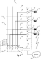
- Fig. 1 illustrates a charging system 10 for electric vehicles 12.
- the charging system 10 has 8 charge ports LP1 to LP8, each having an interface 14 for power exchange with the electric vehicle 12.
- the charging system 10 further comprises five modular energy storage direct converter systems (MESDCS) Ui to U5 and a switchable control matrix 16 as well as a control system 18.
- MESDCS modular energy storage direct converter systems
- the switchable connection matrix 16 is switchable, under control of the control system 18, to selectively connect each of the first terminals 20 with selected one or more second terminals 22.
- each of the first terminals 20 can be selectively connected to each of the second terminals 22. This would allow the largest variety of connection states. However, this is not necessary in practical applications, and in other embodiments, each of the first terminals 20 can only be selectively connected with a subset of said second terminals 22.
- the second end 26 of each MESDCS Ui is connected to ground.
- the connection matrix 16 comprises three third terminals 28, which are connected with a corresponding phase 30A to 30C of a power network 30, which is an example of the "power source" referred to in the summary of the invention.
- each of said third terminals 28 can be selectively connected with selected one or more second terminals 28, such that the first end 24 of each MESDCS Ui can be selectively connected with a phase 30A to 30C of the power network 30, to thereby charge the energy storage elements included in the respective MESDCS Ui, or to feed energy from the energy storage elements of the MESDCS Ui back to the power network 30 in order to stabilize the same.
- the control system 18, which controls the switching states of the connection matrix 16 is configured to ensure at all times that no MESDCS Ui is simultaneously connected to the power network 30 and to a charge port LPj. By this switching constraint, the charge ports LP1 to LP8 are at all times separated from the power network 30. However, since the MESDCS Ui on the one hand and the power network 30 on the other hand are connected to the same ground, there is no full potential separation between the power network 30 and the charge ports LPj yet. An embodiment the full charge separation is shown in Fig. 5 and 6 below.
- the control system 18 For charging an electric vehicle 12 at a given charge port LPj, the control system 18 is configured to establish various charging states. These charging states include a single charging state, in which the control system 18 controls the output voltage of a selected MESDCS Ui to match a desired charging voltage at said given charge port LPj and controls to the connection matrix to connect only the selected MESDCS to said given charge port. In the switching state indicated in Fig. 1 , four of such single charging states are shown with respect to charge ports LP2, LP4, LP6 and LP7. Note that the "desired charging voltage” could be a DC voltage of a certain magnitude, but could also be an AC voltage.
- the MESDCS Ui to U5 are capable of producing practically any desired DC or AC output voltage, under control of the control system 18.
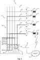
- control system 18 is configured to establish a parallel charging state, in which the control system controls the output voltages of at least two selected MESDCS to each match the desired charging voltage at the given charge port, and controls the connection matrix 16 to connect each of the at least two selected MESDCS to said given charge port.
- a parallel charging state is for example illustrated in Fig. 2 , where four MESDCS U2 to U5 are connected to the same charge port LP7.
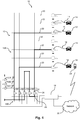
- Fig. 3 and 4 show an embodiment, in which in addition to the single and parallel charging states, also a serial charging state is available, in which the control system 18 controls the output voltages of a group of two or more selected MESDCS (the MESDCS U4 and U5 in Fig. 3 , and the MESDCS U3, U4 and U5 in Fig. 7 ) such that their sum matches a desired charging voltage at a given charge port (LP5), and controls the connection matrix to connect said group of two or more selected MESDCS (U4 and U5 in Fig. 3 ; U3, U4 and U5 in Fig. 4 ) in series, and connect this serially connected group to the given charge port (LP5).
- MESDCS U4 and U5 in Fig. 3 the MESDCS U3, U4 and U5 in Fig. 4
- LP5 connection matrix
- connection matrix 16 comprises a first part 16A, which corresponds to the switching matrix 16 as shown in Fig. 1 and which comprises the first, second and third terminals 20, 22 and 28, and a second part 16B which is switchable, under control of the control system 18, to connect the second ends 26 of selected MESDCS Ui with each other, as is the case for the second ends 26 of MESDCS U4 and U5 in Fig. 3 and Fig. 4 , or to connect the second end 28 of selected MESDCS to ground, as is the case for Ui, U2 and U3 in Fig. 3 and Fig. 4 .
- the first part 16A of the switching matrix 16 is switchable to connect two second terminals 22 witch each other, but not with any of said first terminals 20. This is the case for the second terminals 22 associated with the MESDCS U3 and U4 shown in Fig. 4 .
- the serial charging state by connecting several MESDCS Ui in series, it is possible to generate higher charging voltages at the given charge port (LP5 in Fig. 3 and Fig. 4 ) than within the single or parallel charging state.
- the control system 18 is configured to establish different ones of the single charging state, parallel charging state and serial charging states simultaneously for different charge ports LP1 to LP7.
- Fig. 3 shows a situation in which a single charging state is established for charge port LP3, a parallel charging state is established for charging port LP7, and a serial charging state is established for charge port LP5.
- control system 18 controls the output voltage of one or more selected MESDCS Ui to a lower value than the current voltage of a battery of an electric vehicle 12 connected to a given charge port LPj and controls the switchable connection matrix 16, 16A, 16B to connect the one or more selected MESDCS Ui to the given charge port LPj, such that energy storages within the one or more selected MESDCS Ui are charged with power received from the battery of said electric vehicle 12 connected to the given charge port LPj.
- the charging system 10 "borrows" energy from the vehicles battery, which can then be provided to another vehicle 12 to be charged by the charging system 10, or to the power network 30.
- Power can be provided from the charging system 10 to the power network 30 in the "power source support state" referred to in the summary of the invention, in which the control system 18 controls the output voltage of one or more selected MESDCS Ui to a value higher than a voltage of the power source 30, and controls the connection matrix 16, 16A, 16B to connect said on or more selected MESDCS Ui to the power source 30.
- This can be done to protect the power system, such as the power network 30, if there is a risk of breakdown of the power network.
- the charging system 10 can provide a power safety margin that needs to be kept on reserve at all times to prevent breakdown of a power network 30.
- the power support state can be employed in different grid services, including, but not limited to frequency regulation (frequency containment reserve), peak shaving, spinning reserve, capacity filming, load levelling, power quality, flicker compensation, uninterruptible power supply, reactive power compensation etc.
- the power support state is not only useful for avoiding power failures, but can also be used in a planned way, to support the power network 30 in expected periods of high power demand. This is particularly useful in cases where the charging system 10 is provided in a parking facility, where the vehicles 12 would be connected to the charge ports LP1 to LP8 during the entire time of parking, and could offer the vehicle battery to act as an energy buffer for the power network 30 during the entire parking time, provided that the battery of the vehicle 12 is sufficiently charged at the end of parking. In such applications, there would be a comparatively large number of charge ports LPj that would be served by a comparatively low number of MESDCS Ui.
- the systems 10 shown therein allow not only for connecting a single MESDCS with the power source 30 (or a selected phase thereof), as e.g. shown for MESDCS U1 in Fig. 1 , but also for a parallel connection of two or more MESDCS Ui with the power source 30 (or a selected phase thereof), or, in the case of the systems of Fig. 3 and 4 , for connecting a series connection of two or more MESDCS Ui with the power source 30 (or a selected phase thereof).
- connection matrix 16 may be larger than shown in Fig. 3 and 4 , i.e. may include a larger number of horizontal connection lines to thereby facilitate connecting a larger number of MESDCS Ui in series and to connect this series connection with the power source 30.
- the number of MESDCS Ui may be much larger than shown in the present figures, thereby allowing to connect a significant number of MESDCS in series.
- Fig. 5 shows a further charging system 10 similar to the one of Fig. 4 , which mainly differs in two ways.
- two separate grounds 35, 36 are provided for the power network 30 and the charge ports LPj, respectively.
- the second end 26 of each MESDCS Ui can be selectively connected with the ground 35 associated with the power network 30, in case the first end of the MESDCS Ui is connected with a phase 30A-C of the power network 30.
- MESDCS U1 in Fig. 5 whose first end 24 is connected with phase 30A of the power network 30, and whose second end 26 is connected with the ground 35 of the power network 30.
- any MESDCS Ui that is currently connected with a charge port LPj is connected directly or indirectly with a separate ground 36, which is different from the ground 35 of the power network 30 and which forms a separate ground potential of the charge ports LPj.
- a galvanic separation between the power network 30 and the charge ports LPj is ensured at all times, by the design of the connection matrix 16 and the control provided by the control system 18.
- the second difference is that the charging system 10 of Fig. 5 is associated with an energy consuming entity, which in the shown example is a hospital 37.
- the hospital 37 has a local electricity network 38 which under normal operation is supplied with electrical power by the power network 30 as well.
- the hospital 37 comprises a switching arrangement 39 allowing for decoupling said local electricity network 38 from the power network 30.
- this switching arrangement 39 is formed by three power switches each associated with a corresponding phase 30A to C of the power network 30. Accordingly, in case of a failure of the power network 30, the local electricity network 38 can be separated therefrom and can be maintained, at least in part, with power stored in the MESDCS Ui and possibly the batteries of vehicles 12 currently connected with the charge ports LPj of the charging system 10, as will be described in more detail below.
- the "switching arrangement allowing for coupling some or all of the MESDCS Ui of the charging system 10 with said local electric network 38" that was referred to in the summary of the invention is simply formed by the connection matrix 16, under the control of control system 18, which as described above allows for connecting one or more selected MESDCS Ui with a phase 30A to C of the power network 30, and thereby also allows for connecting the same to the local electricity network 38, as seen from Fig. 5 .
- the control system 18 is configured to establish an associated entity supply mode, in which it controls the output voltages of said MESDCS Ui coupled with said local electric network 38 to provide power of a desired voltage to said hospital 37.
- the "associated entity supply mode” is very similar with the "power source support state", except that in the former the power network 30 is separated from the local electricity network 38, such that the power provided by the charging system 10 is received by the local electricity network 38, and hence the hospital 37, only.
- a typical application for this would be to provide an emergency backup for the case of a power failure of the power network 30, which is of particular importance in case of hospitals.
- the control system 18 is configured to establish reverse charging states for selected charge ports LPj, in which selected MESDCS Ui are charged with power received from the batteries of electric vehicles 12 connected to said selected charge ports LPj.
- Fig. 6 where the hospital 37 and the charging system 10 are separated from the power network 30 by the switching arrangement 39, where Ui, U2 and U4 are connected with corresponding phases of the local electricity network 38, and where U3 and U5 are connected with charge ports LP6 and LP2, respectively, to "borrow" energy from the batteries of the associated vehicles 12 in reverse charging states.
- MESDCS Ui presently connected with the selected charge ports LPj for reverse charging and of MESDCS Ui presently connected with phases of the local electricity network 38 can be interchanged, such that the energy storage elements of the individual MESDCS Ui will be alternatingly charged and discharged.
- Fig. 7 the operation of the charging system 10 of Fig. 1 to 4 according to one embodiment is described.
- the procedure summarized in Fig. 7 starts at step 40, at which an electric vehicle 12 is connected to one of the charge ports LP1 to LP8.
- the vehicle is a "smart vehicle", which automatically transmits charging parameters to the control system 18 via a communication interface associated with the charge port LPj, such as a desired charging voltage and voltage type (DC or AC) and a target charging level, and some parameter related to the charging rate, e.g. an explicit charging rate, a maximum charging period or, similarly, an end of charging time, as well as information regarding a mode of payment and a vehicle or user identification.
- charging parameters e.g. an explicit charging rate, a maximum charging period or, similarly, an end of charging time, as well as information regarding a mode of payment and a vehicle or user identification.
- the interface could be a wire based interface established when the electric vehicle 12 is electrically connected to the charging port LPj.
- charging parameters could also be transmitted via a wireless interface or via communication network as shown under reference signs 32 in Fig. 1 .
- the charging parameters, or additional, more specific charging parameters can be transmitted to the control system 18 using an app installed on a user's portable network enabled device, such as a smart phone 34 (see Fig. 1 ) or on a terminal provided in each charging port LPj or for a group of charging ports LPj.
- step 42 the control system 18 checks the available energy stored in the available MESDCS Ui, and determines the required charging time for possible charging states, such as single charging state, parallel charging state and serial charging state.
- step 44 the control system 18 determines the switching state of the connection matrix 16, 16A, 16B that would allow establishing the desired charging state.
- step 46 it is determined whether a desired charging state can be established that would meet the requested charging parameters. If this is not the case, in step 48, the control system 18 transmits a proposed charging scenario, based on available charging states to the vehicle 12 or to the network enabled portable device 34, offering a possible energy amount that can be provided in the desired time, or a possible charging time for the original requested charging energy.
- the final decision on the charging parameters can be made by the user or in an automated fashion as a result of a negotiation between the smart vehicle 12 and the control system 18.
- step 50 in which the connection matrix 16, 16A, 16B is switched to connect the one or more selected MESDCS Ui to the charge port LPj to establish the selected charging state (single, parallel or serial charging).
- the procedure likewise proceeds to step 50.
- step 52 the vehicle 12 is charged with the determined energy.
- the charging state is regularly checked (step 54) and it is checked in step 56 if the charging is completed. If charging is not completed, the process moves on to step 58, where the availability of the MESDCS, the available energy stored within the MESDCS and the priority of current charging processes is checked. Then, in step 60, it is checked whether there is a change to the availability of the requested charging resources. For example, the availability can change if in the meantime, another vehicle with a high charging priority connects to another charging port, e.g.
- step 52 the process moves again to step 52. However, if there is a change, then the process proceeds to step 48 and transmits an updated possible energy or charging time value to the vehicle 12 or the customer. If there is no answer from the vehicle 12 or the user, in a preferred embodiment, the charging system 10 continues charging with the next highest possible rate available.
- step 56 If it is determined in step 56 that the charging is completed, this is noted in step 62, and in a subsequent step 64, the MESDCS Ui involved in the charging process of this charge port LPj and the corresponding connections in the connection matrix 16, 16A, 16B are released.
- the MESDCS Ui used for charging a vehicle 12 may change during the process in order to balance their states of charge, or if they are needed to establish a requested configuration for charging another vehicle 12 or to provide requested grid support, due to the limited number of combinations in the connection matrix 16. If currently used MESDCS are replaced by another subset of MESDCS during the charging process, the user or smart vehicle 12 will not be notified and the charging process will continue as specified in step 46.
- Fig. 8 shows a closely related process, which mainly differs by the way the user communicates with the control system 18.
- steps 44 to 64 are largely identical to those of Fig. 7 and do not need to be recited again.
- the system starts in step 66 with connecting the vehicle 12 to a charge port LPj.
- the control system 18 checks only the charging voltage and the maximum charging current, but not further charging parameters, such as charging time. Instead, further charging parameters, such as charging time, desired charging energy and/or charging current are selected by the user in step 70, preferably via an app installed on his/her network enabled portable device 34.
- step 72 the control system 18 checks available power, and the possible charging time.
- the following steps 44 to 64 are generally identical to those described in Fig.
- step 48A and 54A the report about the charging state and the information regarding possible energy amount/charging time is communicated to the user.
- This embodiment is particularly useful in cases where the charging system 10 is associated with a parking facility, at which the user leaves his/her vehicle for an extended period of time.
- the charging system could be installed in a parking garage at an airport.
- a user may arrive at the airport and leave his/her car in the parking facility for two days.
- the user could select a parking time of 48 hours and specify that during this time, his battery should be charged up to 75%, so that he/she can safely drive home from the airport. Since the charging demand per vehicle in such a scenario is very low, there can be a large number of charge ports LPj served by a comparatively small number of MESDCS Ui.
- the battery of a parked car can be used as an energy buffer for the charging system 10, and for the power network 30 as whole.
- the energy buffering capacity of the MESDCS Ui and of the batteries of vehicles 12 connected to the charging system 10 can not only be used to support the power network 30, but also to support an energy consuming entity with which the charging system 10 is associated.
- An example of such an energy consuming entity could be the airport referred to in the previous paragraph, but could also be a factory, a train station, hospital or more generally a building or a group of buildings, where the energy consuming entity has a local electricity network which under normal operation is supplied with electrical power by a power network.
- the charging system 10 as well as the batteries of the vehicles 12 currently connected to it can act as a buffer for an emergency backup in case of power failure of the power network 30, or to support the local electric network in case of transient times of high power demand.
- transient power demand peaks can e.g. occur in factories, where a certain machine is started up say only once a day and an excessive amount of energy is needed for this, while the average demand over the day is much less.
- the local electric network can be supported by a charging system 10 during the transient peak energy period. This is also referred to as "peak shaving" in the art.
- the charging system 10 comprises a switching arrangement allowing for coupling some or all of the MESDCS Ui of the charging system 10 with the local electric network for supplying said local electric network with electrical power.
- the control system 18 is configured to establish an associated entity supply mode, in which it controls the output voltages of the MESDCS Ui coupled with the local electric network to provide power of a desired voltage to said associated entity.
- the energy consuming entity then has a switching arrangement allowing for decoupling the local electricity network from the power network 30. This way, it can be ensured that the energy provided in the associated entity supply mode will be used for this entity only, and not dissipate through the currently inoperative local electric network 30.
- Fig. 9 to 19 illustrate various embodiments of the MESDCS Ui as shown in Fig. 1 to 4 .
- Background on MESDCS is disclosed in DE10 2017 110 410 , WO2016/012247 A1 and WO2018/122094 A1 , incorporated herein by reference.
- Fig. 9 shows the general structure of a MESDCS Ui according to an embodiment of the invention.
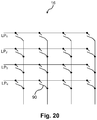
- the MESDCS Ui comprises a converter arm 76 having a first end 24 and a second end 26 and which comprises a plurality of sequentially interconnected modules 78. While in Fig. 9 , only three exemplary modules 78 are shown for illustration purposes, in actual MESDCS, the number of modules 78 canseveral tens or even hundreds . In the simplest version, each module 78 has only one first terminal 80 and one second terminal 82. Examples of such modules 78 are shown in Fig. 10 and Fig. 11 . Moreover, each module 78 comprises an energy storage element 84 or energy conversion element, which in the illustrations of Fig.
- each module 78 comprises a plurality of module switches 86.
- the first terminal 80 of one module is connected with the at least one second terminal of the other module 78.
- the generic symbols for the switches 86 could resemble transistors, in particular MOSFET or bipolar transistors, IGBTs or switchable thyristors.
- the battery 84 can be either deactivated or it can be connected in series with the battery 84 of an adjacent module 78.
- the module 78 shown in Fig. 10 which has a full bridge topology, likewise allows for deactivating or “bypassing" the battery 84 and connecting batteries 84 of adjacent modules 78 in series, but also allows for reversing the polarity of the battery 84 in the connection, which is referred to as "connection in anti-series" for simplicity herein.
- This connection in “anti-series” allows for changing the polarity of the entire converter arms 76 as a whole, which is necessary for handling AC voltages, and is also necessary for the establishing the series connection in the connection matrix 16, 16A, 16B of Fig. 3 , where e.g. the converter arms 76 of the MESDCS U4 and U5 have a different polarities.
- the voltage of the entire converter arm 76 corresponds to the sum of the voltages of the batteries 84 that are currently selected in series.
- the voltage can be decreased, and by activating previously deactivated batteries 84, the voltage can be increased.
- the output voltage can in particular only acquire discrete states. However, due to the typically very large number of modules, the output voltage is sufficiently smooth for the purposes of charging, or establishing a power source support state or a local network support state.
- the effective voltage can be smoothed by connecting and deactivating the battery 84 in one of the modules 78 rapidly in a pulse-width-modulation (PWM) -like manner.
- filter elements may be provided at the end 24 and/or 26, such as choking inductances or capacitors.
- a capacitor allows for smoothing the voltage, which is particularly useful in PWM operation.
- the choke inductance allows for smoothing the current, which allows for meeting network regulations, and also allows for limiting a current rise rate in case of malfunctions. Typical configurations could involve L-filters, LC-filters or LCL filters.
- Fig. 12 shows a schematic example of a further MESDCS Ui, which likewise comprises a converter arm 76 comprising cascaded modules 78, with a main difference that in this case, each module 78 has two first terminals 80a, 80b and two second terminals 82a, 82b.
- the batteries 84 can not only be deactivated and connected selectively in series, but can also be connected in parallel, thereby limiting the internal resistance and hence the losses as compared to the MESDCS with only one first and second terminal 80, 82, each.
- Fig. 13 shows a module 78, which allows for selectively connecting batteries 84 of adjacent modules 78 either in parallel or in series, although it includes only three switches 86. However, this module does not allow for changing the polarity of the voltage.
- Fig. 17 shows several of the modules of Fig.
- Fig. 14 shows a module 78 that provides a higher degree of flexibility. By operating its switches 86, batteries 84 of adjacent modules 78 can be selectively connected in series, in anti-series and in parallel.
- Fig. 15 shows a variant of the module of Fig. 13 , where an additional switch is provided to deactivate its battery 84 when switched in parallel.
- the module of Fig. 16 is a modification of the module of Fig. 14 , where an additional switch is likewise provided which allows for deactivating its battery 84.
- the modules of Fig. 15 and 16 do not only allow for connecting adjacent modules 78 in parallel, but also for connecting modules in parallel which are separated by an arbitrary number of modules 78 with deactivated battery 84. Accordingly, there is a large degree of freedom as to which batteries 84 ought to be connected in parallel.
- the control unit 18 can monitor the voltages of each individual battery 84 and can ensure that the voltages of batteries 84 are balanced by the way they are employed in the generation of the output voltage. For example, batteries 84 with a higher charging state and hence higher voltage would be preferably used in the series connection in an energy outputting mode, such as one of the charging states, the power network support state or the local network support state.
- batteries with a lower charging level and hence lower voltage would be preferably connected to the charging, while batteries with a higher charging level would at first be deactivated. Only when two batteries reach the same or at least similar voltage, they will be connected in parallel.
- the batteries 84 of module 76 which are not directly adjacent, but are separated by one or more modules 76 with deactivated battery 84, can nevertheless be switched in parallel, which is made possible by the module 78 as shown in Fig. 15 and Fig. 16 .
- FIG. 20 schematically shows the principle of the switching matrix 16, in which crossing conductors can be selectively connected at each crossing point using a suitable switch 90. As mentioned before, it is not possible but necessary that such switch 90 is provided at each crossing of the conductors.
Abstract
Description
- The present invention is in the field of electric mobility. More particularly, the present invention relates to a charging system for electric vehicles.
- The number of electric vehicles worldwide is increasing rapidly. Together with the increase in number of electric vehicles, there is a growing demand for charging systems. In prior art charging systems, typically an AC/DC converter is used, for converting an AC voltage provided by a power network to a DC voltage. Since different electric vehicles require different charging voltages, it is generally not possible to simply use this DC voltage directly for simultaneous charging different vehicles at different charge ports. Instead, in a conventional charging system, the DC voltage is supplied to a DC bus, and an additional DC/DC converter is provided between the DC bus and each individual charge port, where the DC/DC converter allows for providing the desired charging voltage.
- These prior art charging systems lack flexibility to meet possibly changing charging demands. Namely, the DC/DC converters are designed for a maximum charging power and for a maximum charging voltage. If new types of electric vehicles become availabe that require higher charging voltages, or higher charging powers, the DC/DC converters have to be replaced. On the other hand, if the DC/DC converters are over-designed to be able to serve all types of vehicles, inefficient use is made of the hardware most of the time.
- A further difficulty with the increasing demand for charging systems is the local supply with power from the power network. The costs for providing additional charging systems increase significantly, if additional medium voltage networks have to be provided for their power supply, such as networks providing a voltage of more than e.g. 1 kV and typically in a range of 10 kV to 50 kV. On the other hand, low-voltage power networks with voltages of less than 1 kV, although available at many places, usually do not provide enough power to charge a plurality of electric vehicles with high charging power at the same time.
-
US 2013/006 9592 A1 discloses a charging system with a plurality of charge ports, a plurality of power converters for converting power from a power source to a desired format for charging a vehicle, and a switchable connection matrix for connecting at least one power converter with at least one charging port. - The problem underlying the invention is to provide a charging system for electric vehicles, that allows for serving different types of vehicles with different charging demands, while making optimum use of the available hardware as well as of the available power supplied from a power source, such as a power network. The electric vehicles may in some embodiments be electric cars, and in the specific examples described herein, reference is mainly made to cars for illustration purposes. However, the invention is not limited to this, but instead generally relates to any type of electric vehicle, including electric cars, motorcycles, scooters, trucks, tractors, boats, or aircrafts.
- This problem is solved by a charging system according to claim 1. Favorable embodiments are defined in the dependent claims. This problem is further solved by a method of operating a charging system according to claim 30. Favorable embodiments of the method are defined in the corresponding dependent claims.
- According to one aspect, the present invention provides a charging system for electric vehicles, comprising a number N of charge ports, each charge port having an interface for power exchange with an electric vehicle, a number of M modular energy storage direct converter systems (MESDCS), a switchable connection matrix, and a control system. Each MESDCS comprises a converter arm having a first end and a second end and comprising a plurality of sequentially interconnected modules, wherein each module comprises
- at least one first terminal and at least one second terminal,
- a storage element for electrical energy, in particular a battery, or an energy conversion element, and
- a plurality of module switches.
- In each two adjacent modules, the at least one first terminal of one module is connected either directly or via an intermediate component to the at least one second terminal of the other module. The said plurality of module switches allow at least for selectively deactivating the storage element or energy conversion element of each module and for connecting storage elements or energy conversion elements of adjacent modules in series. Note that the term "deactivating" a storage element or energy conversion element of the MESDCS has a broad meaning, and shall only indicate that the respective element in its deactivated state does not contribute to the current or voltage provided by the converter arm of the MESDCS. In particular, this can mean that the storage element for electrical energy or energy conversion element is bypassed in a current flow through the MESDCS. In other words, a "deactivated" energy storage or conversion element is not deactivated per se, but is only in a non-active state from the perspective of the MESDCS.
- Moreover, said control system is configured to control an output voltage of each MESDCS, based on information regarding the current charge state of the storage elements or voltage or output power of the energy conversion elements, and by means of actuating at least a part of said plurality of module switches depending on this information such that the converter arm as a whole supplies said output voltage. The switchable connection matrix is configured to connect, under the control of said control system, one or more selected MESDCS with each given charge port, and is further configured to connect one or more selected MESDCS with a power source.
- Herein, the "power source" may typically be an electrical power network, such as a grid or mains network, or a microgrid. However the invention is not limited to this, and the power source may for example be a solar energy plant, one or more wind turbines or the like.
- The control system can be formed by an electric control unit, or a plurality of interconnected control units. Each control unit may comprise one or more microprocessors, or ASICs. The functionality of the control system as disclosed herein can be embodied in hardware, in software, or both.
- The generic term "modular energy storage direct converter system" used herein derives from the fact that it is "modular" by being built up of modules, is capable of storing energy by means of energy storage elements, and is a "direct converter system" in as much as it is designed to actuate at least a part of said plurality of module switches, depending on the current state of charge of the storage elements (or on the current power or voltage of the energy conversion elements) in such way that the converter arm as a whole already supplies a desired output voltage. Indeed, the MESDCS can generally provide arbitrary DC output voltages or AC output voltage waveforms by means of actuating at least a part of said plurality of module switches. This way, when an MESDCS is connected to a charge port, it can provide any desired charging voltage, and in particular, both DC and AC voltages. Moreover, the same flexibility as with regard to the output voltages exists for the charging of the energy storage elements, which can be charged with practically any voltage applied across the converter arm, including both DC and AC voltages. Accordingly, when one or more selected MESDCS are connected with said power source, their corresponding energy storage elements can be charged by said power source. An MESDCS is described in
WO2016/012247 A1 . - Accordingly, the MESDCS does not only allow for converting the voltage from the power source to the desired charging voltage at the charge port, but also allows for storing energy, such that it acts as an energy buffer. This allows for providing high transient total charging powers at plural charge ports that may exceed the power that can be provided by the power source, if there is a high demand for vehicle charging, and for refilling the energy storage elements when there is less charging demand at the charging ports.
- While in the specific embodiments described herein, each of the modules comprise a battery, it is noted that the invention is not limited to this, as the invention is also applicable to systems where other energy storage elements are employed, for example redox flow cells or capacitors, or to systems where at least part of the modules comprise energy conversion elements such as solar cells, fuel cells or thermocouple elements. Accordingly, wherever in the following description explanations are made with regard to a system based on batteries, it is to be understood that the corresponding disclosure should relate, where applicable, also to other forms of energy storage elements, or energy conversion elements, without further mention.
- The MESDCS as defined above has a number of important advantages. For example, since the voltages associated with each individual energy storage element/energy conversion element can be comparatively low, the module switches do not have to switch high voltages. This for example allows for using standard low-voltage silicon MOSFETs instead of more expensive IGBTs or silicon carbide-MOSFETs. Moreover, switching of lower voltages by the module switches allows for a better electromagnetic compatibility and reduced total harmonic distortion.
- In preferred embodiments, the control system is configured to ensure that no MESDCS is simultaneously connected to a phase of the power source and to a charge port. This way, the potentials of the charge ports can be automatically separated from the potential of the phases of the power source. A full separation of the potentials of the power source on the one hand and the charge ports/electric vehicles on the other hand can then be easily obtained e.g. by ensuring that when connecting an MESDCS with a given charge port, it is not simultaneously connected with the same ground as the power source. For this purpose, a separate ground for the MESDCS can be provided, and connected with an MESDCS directly or indirectly (e.g. via a further MESDCS) when the MESDCS is connected with the charge port. Conversely, when an MESDCS is connected with the power source, or more precisely a phase of the power source, it may be further connected directly or indirectly with the ground associated with the power source. Switching between the two grounds can likewise be established by the switching matrix.
- Accordingly, in a preferred embodiment, the connection matrix is configured to connect, under control of said control system, one or more selected MESDCS directly or indirectly with a ground associated with the power source, when said one or more selected MESDCS is connected with a phase of said power source, and to disconnect said one or more selected MESDCS from the ground of the power source when said one or more selected MESDCS are connected with a charge port.
- For charging an electric vehicle at a given charge port with a desired charging voltage, in preferred embodiments, the control system is configured to establish at least two, and preferably all of the following charging states:
- a single charging state, in which the control system controls the output voltage of a selected MESDCS to match said desired charging voltage at said given charge port, and controls the connection matrix to connect only the selected MESDCS to said given charge port,
- a parallel charging state, in which the control system controls the output voltages of at least two selected MESDCS to each match said desired charging voltage at said given charge port, and controls the connection matrix to connect each of the at least two selected MESDCS to said given charge port, and
- a serial charging state, in which the control system controls the output voltages of a group of two or more selected MESDCS such that their sum matches said desired charging voltage at said given charge port, and controls the connection matrix to connect said group of two or more selected MESDCS in series and to connect said serially connected group to said given charge port.
- Herein, the parallel charging state allows for higher charging current than possible with a single MESDCS, to allow for particularly rapid charging at said given charge port. Moreover, the serial charging state allows for providing particularly high charging voltages. In both cases, the individual MESDCS do not have to be dimensioned for particularly high output voltages or output currents, instead, they can be combined in the parallel or serial charging state only when there is corresponding demand for high voltage and such a high current charging.
- Note that the single charging state does not rule out that the single selected MESDCS connected to said given charge port is also connected to another charge port, in which case the given charge port and the other charge port would be connected in parallel to the single selected MESDCS. However, in preferred embodiments, the single charging state is a state in which one and only one MESDCS is connected to one and only one charge port.In preferred embodiments, said control system is configured to establish different ones of said single charging state, parallel charging state and serial charging state simultaneously for different charge ports.
- In a preferred embodiment, said control system is configured to establish a reverse charging state, in which the control system controls the output voltage of one or more selected MESDCS to a value lower than the current voltage of a battery of an electric vehicle connected to a given charge port, and controls the switchable connection matrix to connect said one or more selected MESDCS to said given charge port, such that energy storages within said one or more selected MESDCS are charged with power received from the battery of said electric vehicle connected to said given charge port. The appropriate value of the output voltage of the one or more selected MESDCS for the reverse charging depends on the present impedance and can be adjusted such as to establish a desired charging current or charging power. Graphically speaking, in the reverse charging state, the charging system "borrows" energy from the vehicle's battery, thereby effectively extending the "buffering capability" inherent to the MESDCS to vehicles connected with a charge port. This can for example be useful when the charging system is used for stabilizing the power source (e.g. mains network) to which it is connected.
- Preferably, said control system is configured to establish a power source support state, in which the control system controls the output voltage of one or more selected MESDCS to a value higher than a voltage of the power source and controls the connection matrix to connect said one or more selected MESDCS to said power source. Again, the appropriate value of the output voltage of the one or more selected MESDCS for the power source support state depends on the present impedance and can be adjusted such as to establish a desired current or power. In the power source support state, energy is provided from the MESDCS to the power source. This can be expedient if there is a risk of power failure or blackout, and where the power source (e.g. mains network) can be stabilized by the MESDCS in the power source support state. However, feeding energy from the MESDCS to the power source is not only useful for emergency cases, but can be done in a routine way to compensate for expected peaks in power demand. In particular, by alternately employing the reverse charging state and the power source support state, effectively energy can be transferred from the vehicle batteries to the power source as part of the routine operation of the charging system, such that not only the MESDCS, but also the vehicle batteries act as buffers for the power system. This is particularly useful when the charging system is used for parking cars, where there is no particular time demand for charging.
- Note that the above-mentioned feature, according to which the switchable connection matrix is "configured to connect, under the control of said control system, one or more selected MESDCS with each given charge port", may involve connecting a single MESDCS with a given charge port, connecting a parallel connection of two or more MESDCS with a given charge port, or connecting a series connection of two or more MESDCS with a given charge port, as is the case in the single, parallel and serial charging states, respectively. However, the same single, parallel and series connections of the MESDCS with the charge ports can also be employed in the reverse charging states. In particular, when a series connection of two or more MESDCS are connected with the charge port in the reverse charging state, said "output voltage of the one or more selected MESDCS" corresponds to the sum of the individual voltages of the MESDCS connected in series, and this total voltage may then be controlled to be lower than the voltage of the battery of the vehicle connected to said charge port. In other words, the main difference between the charging state and the reverse charging state is the direction of flow of energy, while the connections that can be provided by the connection matrix may be the same in both, the charging and reverse charging mode.
- Similarly, the above-mentioned feature, according to which the switchable connection matrix is "configured to connect, under the control of the control system, one or more selected MESDCS with a power source" may involve connecting a single MESDCS with the power source (or a selected phase thereof), connecting a parallel connection of two or more MESDCS with the power source (or a selected phase thereof), or connecting a series connection of two or more MESDCS with the power source (or a selected phase thereof). Again, this applies both, to cases in which the MESDCS are to be charged by the power source, as well as to cases where the MESDCS provide energy to the power source in the power source support state. In particular, the possibility to connect a series connection of two or more MESDCS with the power source (or a selected phase thereof) may be advantageous in cases where the voltage of the power source is higher or even much higher than the voltage of the batteries to be charged. For example, consider a case where the battery of the vehicle has 400 V and the power source has 2 kV. If only single MESDCS were to be connected with the power source, the MESDCS would have to be designed to provide a voltage of 2 kV as well, i.e. need a corresponding number of modules. This would not be an efficient use of hardware if only 400 V are required for charging. However, when the connection matrix is able to connect a series connection of say five MESDCS with the power source, each of the MESDCS would receive only 400 V, and it would hence be sufficient to design each of the MESDCS for this lower voltage, thereby making optimum use of the hardware.
- In preferred embodiments, connecting said one or more selected MESDCS to said power source in said power source support state comprises connecting said one or more selected MESDCS to a given phase of said power source, wherein the control system further controls the output voltage of said one or more selected MESDCS to follow a time varying phase voltage of said power source phase, such that it is at each instance in time higher than the time varying phase voltage , again exploiting "direct converter" capabilities of the MESDCS to output the optimum voltage waveform for supporting the AC phase of the power source. Note that the "output voltage being higher than the phase voltage" means that its magnitude is higher and that its polarity is the same as that of the phase voltage, such that MESDCS output voltage indeed at all times supports the power source phase voltage. Note that as before, the output voltage of the MESDCS is controlled such that a desired power flow or exchange of energy is obtained. In other words, while the power flow is the quantity of practical interest, the controllable output voltage of the MESDCS is adjusted such as to obtain such power flow, and in this case, a power flow that supports the power source. Note further that both, the reverse charging state and the power support state can be maintained for extended periods of time, i.e. a minute or more, 10 minutes or more, 30 minutes or more, or even an hour or more. However, the duration of the reverse charging state and the power support state can be much shorter, on the order of seconds or even below, and they can be established intermittently, depending on the technical demand. For example, when the power support mode is used for purposes such as peak shaving, the power support mode can be comparatively short, on the order of seconds or minutes, while for purposes such as capacity firming, such as to account for fluctuations in power generated by e.g. wind or sun, the power support mode could be established for longer periods of time, for example half an hour or longer.
- In some embodiments, said switchable connection matrix has a first part, said first part comprising N first terminals each connected with a corresponding one of said N charge ports, and M second terminals, each connected with a first end of a corresponding MESDCS, and wherein said switchable connection matrix is switchable, under control of said control system, to selectively connect each of said first terminals with selected one or more second terminals. Note that it is possible, but not necessary that each of the first terminals can be selectively connected to each of the second terminals. While this would give the most flexibility regarding the connection states, in practical applications this will often not be necessary. However, in preferred embodiments of the invention, each of the first terminals can at least be selectively connected with a subset of said second terminals.
- Preferably, said first part of said switchable connection matrix further comprises a number of L third terminals each connected to a corresponding phase of said power source or to ground, wherein said switchable connection matrix is switchable, under control of said control system, to selectively connect each of said third terminals with selected one or more second terminals.
- In a preferred embodiment, said switchable connection matrix is further switchable, under control of said control system, to connect two second terminals with each other, but not with any of said first terminals.
- In a preferred embodiment, said switchable connection matrix has a second part, wherein said second part of said switchable connection matrix is switchable, under control of said control system, to connect the second ends of two selected MESDCS with each other, or to connect the second end of selected MESDCS to ground.
- In a preferred embodiment, said power source is a low voltage network having a DC voltage of up to 1500 V, or an AC voltage up to 1000 V, and in particular a 230/400-volt-network or a 110 V network as customary in the USA. Such low voltage networks are widely available, such that charging systems according to this embodiment can be provided at a large variety of locations without having to provide additional or extend existing power networks. While the total power that can be provided at such low voltage networks is limited, due to the buffering provided by the energy storage elements of the MESDCS, it is nevertheless possible to provide fairly high transient charging powers, and refilling the energy storage elements at times of lower charging demands, such that the limited power provided by the low-voltage network is optimally used for efficient charging.
- In alternative embodiments, said power source is a medium voltage network, with a voltage between 1 kV and 60 kV, preferably between 1 kV and 30 kV..
- In various embodiments, the number N of charge ports is 3 or more, preferably 5 or more, more preferably 10 or more, and most preferably 50 or more.
- In some embodiments, the charging system is configured for rapid charging, and in this case, the number M of MESDCS is preferably larger than the number N of charge ports, and in particular M:N ≥ 1.25, preferably M:N ≥ 1.5, and most preferably M:N ≥ 2.0. A higher ratio M:N means that there are more MESDCS available for establishing serial charging states and parallel charging states, which in turn allow for higher charging powers and hence shorter charging times. This is particularly useful for charging systems provided at roadsides of high traffic roads, such as highways or turnpikes, where most users wish to stop only shortly for charging. Various embodiments of the present invention allow for charging powers of 50 kW or more, preferably 150 kW or more or even 300 kW or more. High charging powers can be readily provided in the framework of the present invention due to the possibility of connecting two or more MESDCS in parallel and/or in series.
- In alternative embodiments, the charging system is provided in a parking facility, where vehicles will be parked for appreciable periods of time, and where there is generally no need for rapid charging. In this case, the number N of charge ports is larger than the number M of MESDCS, and in particular N:M ≥ 1.5, preferably N:M ≥ 3.0, and most preferably N:M ≥ 5.0. This will allow for providing charging infrastructure to a large number of parked vehicles with a comparatively low number of MESDCS, and hence low cost of the charging system.
- In preferred embodiments, the charging system is associated with an energy consuming entity, in particular a factory, an airport, a train station, a hospital, a building or a group of buildings, wherein said energy consuming entity has a local electricity network, which under normal operation is supplied with electrical power by a power source, which may but need not be the same power source as that to which the charging system is connected, wherein said charging system comprises a switching arrangement allowing for coupling some or all of the MESDCS of the charging system with said local electric network for supplying said local electric network with electrical power, and wherein said control system is configured to establish an associated entity supply mode, in which it controls the output voltages of said MESDCS coupled with said local electric network to provide power of a desired voltage to said associated entity.
- In a related embodiment, said switching arrangement allowing for coupling some or all of the MESDCS of the charging system with said local electric network is provided by said connection matrix, and said coupling is carried out under control of said control system, and in particular, by connecting selected ones or all of said third terminals to a corresponding phase of said local electric network. In this embodiment, the same third terminals that would be connected for example to the phases of a power network in the power source support state can hence be connected to the phases of the local electric network. Herein, said energy consuming entity may comprise a switching arrangement allowing for decoupling said local electrical network from its power source, thereby ensuring that the energy provided to the local electric network does not dissipate to the power network, in particular in situations where the power network is failing.
- In preferred embodiments, the associated entity supply mode is one of an emergency backup mode to be activated in case of power failure in the power source, and a peak shaving mode, which is to be activated in case of transient demand for high power in the local electric network of said associated entity.
- During said associated entity supply mode, said control system is preferably configured to establish reverse charging states for selected charge ports, in which selected MESDCS are charged with power received from the batteries of electric vehicles connected to said selected charge ports. This way, energy from the electric vehicles can be transferred to the associated entity, thereby effectively increasing the buffering capacity of the MESDCS by the capacity of the batteries of the vehicles currently connected to the charging system.
- In a preferred embodiment, a communication interface is associated with each charge port, allowing for transmitting charging parameters to the control system. Herein, the charging parameters may comprise one or more parameters selected from the group consisting of a desired charging voltage, a target charging level, a charging rate, a charging power, a maximum charging period, an end of charging time, information regarding a mode of payment, a vehicle identification, and a user identification. The communication interface may be a wire based interface established when the electric vehicle is electrically connected to said charging port. In particularly preferred embodiments, the charging information is provided, at least in part, automatically by the electric vehicle. Vehicles capable of automatically providing the charging information are also referred to as "smart vehicles" herein.
- In alternative embodiments, the communication interface is a wireless interface, or is provided by a communication network, such as the Internet. In related embodiments, said control system is configured for communicating with an App to be installed on a user's portable network enabled device for transmitting said charging parameters. This is particularly useful in cases where the charging system is associated with a parking facility, i.e. where the electric vehicle will be connected to the charging point for an extended period of time. For example, if the charging parameter included an end of charging time at noon time, but the vehicle owner changes plans and decides to only pick up his/her car the next morning, he/she can communicate this via the app, and this can be considered in the charging strategy that is carried out by the control system. For example, close to noontime or in the early evening, where there is a high demand for energy, the energy contained in the vehicle's battery can be "borrowed" by one of the MESDCS using the reverse charging mode, and can be resupplied at night time, where there will be less demand for energy in the power network, and power can be obtained at a lower price.
- In a preferred embodiment, said communication interface allows for communicating information regarding the charging process from the control system to the electric vehicle or a network enabled device, in particular information whether one or more of a requested charging rate, target charging level, maximum charging period or end of charging time can currently be provided, and if this is not the case, suggest alternative charging parameters that can be provided.
- In a preferred embodiment, the control system is configured to receive, via said communication interfaces associated with said charge ports, charging parameters, and to establish a charging strategy based on said received charging parameters, wherein establishing a charging strategy comprises selecting, for each of said ports for which charging parameters have been received, a charging state or a time sequence of charging states, selected from the following charging states:
- an idle state, in which no charging takes place,
- a single charging state, in which the control system controls the output voltage of a selected MESDCS to match a desired charging voltage at a given charge port, and controls the connection matrix to connect only the selected MESDCS to said given charge port,
- a parallel charging state, in which the control system controls the output voltages of at least two selected MESDCS to each match a desired charging voltage at a given charge port, and controls the connection matrix to connect each of the at least two selected MESDCS to said given charge port,
- a serial charging state, in which the control system controls the output voltages of a group of two or more selected MESDCS such that their sum matches a desired charging voltage at a given charge port, and controls the connection matrix to connect said group of two or more selected MESDCS in series and to connect said serially connected group to said given charge port, and
- a reverse charging state, in which the control system controls the output voltage of one or more selected MESDCS to a value lower than the current voltage of a battery of an electric vehicle connected to a given charge port, and controls the switchable connection matrix to connect said one or more selected MESDCS to said given charge port, such that energy storages within said one or more selected MESDCS are charged with power received from the battery of said electric vehicle connected to said given charge port.
- In preferred embodiments, said control system is configured to establish said charging strategy, at least in part, based on a prognosis of future charging demands. For example, future charging demands can be predicted quite reliably based on statistical and empirical information.
- In a preferred embodiment, said plurality of module switches of the modules further allow for selectively connecting storage elements or energy conversion elements of adjacent modules in anti-series. "connection in anti-series", as opposed to "connection in series" means a connection with reversed polarity. The possibility of connecting an individual module in anti-series can for example be helpful for measuring the state of health or the state of charge of the batteries included in the modules. However, the capability of freely changing their polarity of the energy storage elements in the series connection implies that the polarity of the MESDCS as a whole can be changed, allowing for providing positive and negative output voltages.
- In preferred embodiments, at least the modules which are not the first and last in the sequential interconnection in the MESDCS each comprise at least two first terminals and at least two second terminals, wherein in each two adjacent modules the at least two first terminals of one module are connected either directly or via an intermediate component to a corresponding one of the at least two second terminals of the other module, and wherein said plurality of module switches of the modules further allow for selectively connecting storage elements or energy conversion elements of adjacent modules in parallel. This way, the internal resistance of the energy storage direct converter and hence the internal loss can be reduced.
- In a particularly preferred embodiment, the plurality of module switches of the MESDCS modules allow for connecting storage elements or energy conversion elements of modules which are separated by at least one intermediate module with a deactivated storage element/conversion element selectively in parallel and in series. This variant has at least two significant advantages. One advantage is that in case one of the modules or its energy storage should be defective, the operation of the remaining modules is not compromised. The other advantage is that even non-adjacent energy storage elements/conversion elements can be selectively switched in parallel. This allows for selectively connecting energy storage/conversion elements in parallel that have identical or at least similar voltages to thereby avoid balancing currents/charge transfer between energy source/conversion elements, which would only lead to internal losses.
- A further aspect of the invention relates to a method of operating a charging system for electric vehicles, said charging system comprising:
- a number N of charge ports, each charge port having an interface for power exchange with an electric vehicle,
- a number of M modular energy storage direct converter systems (MESDCS),
- a switchable connection matrix, and
- a control system,
- wherein each MESDCS comprises a converter arm having a first end and a second end and comprising a plurality of sequentially interconnected modules, wherein each module comprises
- at least one first terminal and at least one second terminal,
- a storage element for electrical energy, in particular a battery, or an energy conversion element, and
- a plurality of module switches,
- wherein in each two adjacent modules the at least one first terminal of one module is connected either directly or via an intermediate component to the at least one second terminal of the other module,
- wherein said plurality of module switches allow at least for selectively deactivating the storage element or energy conversion element of each module and for connecting storage elements or energy conversion elements of adjacent modules in series,
- wherein said method comprises controlling an output voltage of each MESDCS, based on information regarding the current charge state of the storage elements or voltage or output power of-energy conversion elements, by actuating at least a part of said plurality of module switches depending on this information such that the converter arm as a whole supplies said output voltage,
- and wherein said operation comprises connecting one or more selected MESDCS with each given charge port, and comprises connecting one or more selected MESDCS with a power source.
- In a preferred embodiment, the method is carried out such that it is constantly avoided that any MESDCS is simultaneously connected to the power source and to a charge port, wherein the method preferably further comprises selectively connecting, by means of said connection matrix, one or more MESDCS directly or indirectly with a ground associated with the power source, when said one or more selected MESDCS is connected with a phase of said power source, and disconnecting said one or more MESDCS from the ground of the power source when said one or more selected MESDCS are connected with a charge port.
- In a preferred embodiment, for charging an electric vehicle at a given charge port with a desired charging voltage, the method comprises establishing at least two, and preferably all of the following charging states:
- a single charging state, in which the control system controls the output voltage of a selected MESDCS to match said desired charging voltage at said given charge port, and controls the connection matrix to connect only the selected MESDCS to said given charge port,
- a parallel charging state, in which the control system controls the output voltages of at least two selected MESDCS to each match said desired charging voltage at said given charge port, and controls the connection matrix to connect each of the at least two selected MESDCS to said given charge port, and
- a serial charging state, in which the control system controls the output voltages of a group of two or more selected MESDCS such that their sum matches said desired charging voltage at said given charge port, and controls the connection matrix to connect said group of two or more selected MESDCS in series and to connect said serially connected group to said given charge port.
- In a preferred embodiment, said method comprises establishing different ones of said at least two, preferably three charging states simultaneously for different charge ports.
- In a preferred embodiment, said method further comprises establishing a reverse charging state, in which the output voltage of one or more selected MESDCS is controlled to assume a value lower than the current voltage of a battery of an electric vehicle connected to a given charge port, and the switchable connection matrix is controlled to connect said one or more selected MESDCS to said given charge port, such that energy storages within said one or more selected MESDCS are charged with power received from the battery of said electric vehicle connected to said given charge port.
- In a preferred embodiment, said method further comprises establishing a power source support state, in which the output voltage of one or more selected MESDCS is controlled to assume a value higher than a voltage of the power source and the connection matrix is controlled to connect said one or more selected MESDCS to said power source.
- In a preferred embodiment, connecting said one or more selected MESDCS to said power source in said power source support state comprises connecting said one or more selected MESDCS to a given phase of said power source, wherein the method further comprises controlling the output voltage of said one or more selected MESDCS to follow a time varying phase voltage of said power source phase, such that it is at each instance in time higher than the time varying phase voltage.
- In a preferred embodiment, said switchable connection matrix has a first part, said first part comprising N first terminals each connected with a corresponding one of said N charge ports, and M second terminals, each connected with a first end of a corresponding MESDCS, and wherein said switchable connection matrix is switchable, under control of said control system, to selectively connect each of said first terminals with selected one or more second terminals.
- In a preferred embodiment, said first part of said switchable connection matrix further comprises a number of L third terminals each connected to a corresponding phase of said power source or to ground, wherein said method comprises selectively connecting each of said third terminals with selected one or more second terminals.
- In a preferred embodiment, said method further comprises a step of connecting two second terminals with each other, but not with any of said first terminals.
- In a preferred embodiment, said switchable connection matrix has a second part, wherein said second part of said switchable connection matrix is switchable, under control of said control system, to connect the second ends of two selected MESDCS with each other, or to connect the second end of selected MESDCS to ground.
- In a preferred embodiment, said power source is
- a low voltage network having a DC voltage of up to 1500 V, or an AC voltage up to 1000 V, and in particular a 230/400-volt-network or a no-volt-network, or
- a medium voltage network, with a voltage between 1 kV and 60 kV, preferably between 1 kV and 30 kV..
- In a preferred embodiment, the number N of charge ports is 3 or more, preferably 5 or more, more preferably 10 or more, and most preferably 50 or more.
- In a preferred embodiment, the number M of MESDCS is larger than the number N of charge ports, and in particular M:N ≥ 1.25, preferably M:N ≥ 1.5, and most preferably M:N ≥ 2.0.
- In a preferred embodiment, the charging system is provided in a parking facility, and wherein the number N of charge ports is larger than the number M of MESDCS, and in particular N:M≥ 1.5, preferably N:M ≥ 3.0, and most preferably N:M ≥ 5.0.
- In a preferred embodiment, the charging system is associated with an energy consuming entity, in particular a factory, an airport, a train station, a hospital, a building or a group of buildings, wherein said energy consuming entity has a local electricity network, which under normal operation is supplied with electrical power by a power source, wherein said charging system comprises a switching arrangement allowing for coupling some or all of the MESDCS of the charging system with said local electric network for supplying said local electric network with electrical power, and wherein said method comprises establishing an associated entity supply mode, in which the output voltages of said MESDCS coupled with said local electric network are controlled to provide power of a desired voltage to said associated entity.
- In a preferred embodiment, said switching arrangement allowing for coupling some or all of the MESDCS of the charging system with said local electric network is provided by said connection matrix, and said coupling is carried out under control of said control system, and in particular, by connecting selected ones or all of said third terminals to a corresponding phase of said local electric network.
- Preferably, the method further comprises a step of decoupling said local electricity network from its power source.
- In a preferred embodiment, said associated entity supply mode is one of an emergency backup mode to be activated in case of power failure in the power source, and a peak shaving mode, which is to be activated in case of transient demand for high power in the local electric network of said associated entity.
- Preferably, the method further comprises establishing, during said associated entity supply mode, reverse charging states for selected charge ports, in which selected MESDCS are charged with power received from the batteries of electric vehicle connected to said selected charge ports.
- In a preferred embodiment, a communication interface is associated with each charge port, wherein charging parameters are transmitted to the control system, wherein said charging parameters comprise one or more parameters selected from the group consisting of a desired charging voltage, a target charging level, a charging rate, a charging power, a maximum charging period, an end of charging time, information regarding a mode of payment, a vehicle identification, and a user identification.
- In a preferred embodiment, said communication interface is a wire based interface established when the electric vehicle is electrically connected to said charging port, wherein preferably, the charging information is provided, at least in part, automatically by the electric vehicle.
- In a preferred embodiment, said communication interface is a wireless interface, or provided by a communication network, such as the Internet, wherein in particular, the method comprises a step in which the control system communicates with an application software installed on a user's portable network enabled device for transmitting said charging parameters.
- The method preferably further comprises a step of communicating information regarding the charging process from the control system to the electric vehicle or a network enabled device, in particular information whether one or more of a requested charging rate, target charging level, maximum charging period or end of charging time can currently be provided, and if this is not the case, a step of suggesting alternative charging parameters that can be provided.
- The method preferably further comprises a step of receiving, via said communication interfaces associated with said charge ports, charging parameters, and establishing a charging strategy based on said received charging parameters, wherein establishing a charging strategy comprises selecting, for each of said ports for which charging parameters have been received, a charging state or a time sequence of charging states, selected from the following charging states:
- an idle state, in which no charging takes place,
- a single charging state, in which the control system controls the output voltage of a selected MESDCS to match a desired charging voltage at a given charge port, and controls the connection matrix to connect only the selected MESDCS to said given charge port,
- a parallel charging state, in which the control system controls the output voltages of at least two selected MESDCS to each match a desired charging voltage at a given charge port, and controls the connection matrix to connect each of the at least two selected MESDCS to said given charge port,
- a serial charging state, in which the control system controls the output voltages of a group of two or more selected MESDCS such that their sum matches a desired charging voltage at a given charge port, and controls the connection matrix to connect said group of two or more selected MESDCS in series, and to connect said serially connected group to said given charge port, and
- a reverse charging state, in which the control system controls the output voltage of one or more selected MESDCS to a value lower than the current voltage of a battery of an electric vehicle connected to a given charge port, and controls the switchable connection matrix to connect said one or more selected MESDCS to said given charge port, such that energy storages within said one or more selected MESDCS are charged with power received from the battery of said electric vehicle connected to said given charge port.
- In a preferred embodiment, the method further comprises a step of establishing said charging strategy, at least in part, based on a prognosis of future charging demands.
- In a preferred embodiment, the method further comprises a step of establishing the charging strategy, at least in part, based on the availability or the price of electric power provided from said power source, or a prognosis thereof.
- In a preferred embodiment, said plurality of module switches of the modules of each MESDCS further allow for selectively connecting storage elements or energy conversion elements of adjacent modules in anti-series.
- In a preferred embodiment, at least the modules which are not the first and last in the sequential interconnection each comprise at least two first terminals and at least two second terminals, wherein in each two adjacent modules the at least two first terminals of one module are connected either directly or via an intermediate component to a corresponding one of the at least two second terminals of the other module, wherein said plurality of module switches of the modules further allow for selectively connecting storage elements or energy conversion elements of adjacent modules in parallel, and preferably allow for connecting storage elements or energy conversion elements of modules which are separated by at least one intermediate module with a deactivated storage element/conversion element selectively in parallel and in series.
- In preferred embodiments, the method of the invention is carried out using a charging system according to any of the embodiments described above. Moreover, the present disclosure also relates to any combination of the various embodiments of the system and of the method recited above.
-
- Fig. 1
- is a schematic representation of a charging system according to an embodiment of the invention, in which single charging states are established.
- Fig. 2
- is a schematic representation of a charging system according to an embodiment of the invention, in which a single and a parallel charging state are established.
- Fig. 3
- is a schematic representation of a charging system according to an embodiment of the invention, in which a single charging state, a parallel charging state and a serial charging state are established.
- Fig. 4
- is a schematic representation of a charging system according to an embodiment of the invention, in which two single charging states and one serial charging state are established.
- Fig. 5
- is a schematic representation of a charging system according to an embodiment of the invention, in which the power source and the charge ports are galvanically separated from each other, and in which the charging system is associated with a hospital having a local electricity network.
- Fig. 6
- is a schematic representation of the charging system according to
Fig. 5 , in which an entity supply mode is established, in which the hospital is supplied with electrical power from the charging system. - Fig. 7
- is a flow diagram illustrating a charging process using the system of
Fig. 1 to 4 . - Fig. 8
- is a further flow diagram illustrating a charging process using the charging system of
Fig. 1 to 4 . - Fig. 9
- is a schematic representation of a MESDCS,
- Fig. 10 and 11
- show modules that can be used in the MESDCS of
Fig. 9 , - Fig. 12
- is a schematic illustration of a further MESDCS,
- Fig. 13 to 16
- illustrate modules that can be used in the MESDCS of
Fig. 12 , - Fig. 17
- shows an MESDCS incorporating module as shown in
Fig. 15 , - Fig. 18
- shows an MESDCS incorporating modules as shown in
Fig. 16 , - Fig. 19
- is a schematic representation of the connection of the batteries in the MESDCS of
Fig. 17 and 18 , and - Fig. 20
- is a schematic representation of a switchable connection matrix.
- For the purposes of promoting an understanding of the principles of the invention, reference will now be made to a preferred embodiment illustrated in the drawings, and specific language will be used to describe the same. It will nevertheless be understood that no limitation of the scope of the invention is thereby intended, such alterations and further modifications in the illustrated apparatus and such further applications of the principles of the invention as illustrated therein being contemplated as would normally occur now or in the future to one skilled in the art to which the invention relates.
-
Fig. 1 illustrates a chargingsystem 10 forelectric vehicles 12. In the embodiment shown, the chargingsystem 10 has 8 charge ports LP1 to LP8, each having aninterface 14 for power exchange with theelectric vehicle 12. Moreover, the chargingsystem 10 further comprises five modular energy storage direct converter systems (MESDCS) Ui to U5 and aswitchable control matrix 16 as well as acontrol system 18. The structure and operation of the MESDCS Ui to U5 will be described in more detail with reference toFig. 9 to 19 below. - The
switchable connection matrix 16 has eightfirst terminals 20, each port connected with a corresponding one of said eight charge ports LP1 to LP8. Further, theswitchable connection matrix 16 has sixsecond terminals 22 each connected with afirst end 24 of a corresponding MESDCS Ui (with i=1,....,5). InFig. 1 to 4 , the connection of afirst terminal 20 with asecond terminal 22 is indicated by a thick line. Accordingly, in the switching state of theswitchable connection matrix 16 illustrated inFig. 1 , thefirst terminal 20 associated with charge port LP2 is connected with thesecond terminal 22 associated with thefirst end 24 of MESDCS U5, and thefirst terminal 20 associated with charge port LP7 is connected with thesecond terminal 22 associated with thefirst end 24 of MESDCS U2. As mentioned in the summary of the invention, theswitchable connection matrix 16 is switchable, under control of thecontrol system 18, to selectively connect each of thefirst terminals 20 with selected one or moresecond terminals 22. In some embodiments, each of thefirst terminals 20 can be selectively connected to each of thesecond terminals 22. This would allow the largest variety of connection states. However, this is not necessary in practical applications, and in other embodiments, each of thefirst terminals 20 can only be selectively connected with a subset of saidsecond terminals 22. As is seen fromFig. 1 , by connecting one of thefirst terminals 20 with a selected one of thesecond terminals 22, a corresponding charge port LPj (with j=1,....,8) is connected with thefirst end 24 of a corresponding MESDCS Ui. In the embodiment ofFig. 1 , thesecond end 26 of each MESDCS Ui is connected to ground. - As further shown in
Fig. 1 , theconnection matrix 16 comprises threethird terminals 28, which are connected with acorresponding phase 30A to 30C of a power network 30, which is an example of the "power source" referred to in the summary of the invention. Under control of thecontrol system 18, each of saidthird terminals 28 can be selectively connected with selected one or moresecond terminals 28, such that thefirst end 24 of each MESDCS Ui can be selectively connected with aphase 30A to 30C of the power network 30, to thereby charge the energy storage elements included in the respective MESDCS Ui, or to feed energy from the energy storage elements of the MESDCS Ui back to the power network 30 in order to stabilize the same. - Importantly, in the shown embodiment, the
control system 18, which controls the switching states of theconnection matrix 16, is configured to ensure at all times that no MESDCS Ui is simultaneously connected to the power network 30 and to a charge port LPj. By this switching constraint, the charge ports LP1 to LP8 are at all times separated from the power network 30. However, since the MESDCS Ui on the one hand and the power network 30 on the other hand are connected to the same ground, there is no full potential separation between the power network 30 and the charge ports LPj yet. An embodiment the full charge separation is shown inFig. 5 and6 below. - For charging an
electric vehicle 12 at a given charge port LPj, thecontrol system 18 is configured to establish various charging states. These charging states include a single charging state, in which thecontrol system 18 controls the output voltage of a selected MESDCS Ui to match a desired charging voltage at said given charge port LPj and controls to the connection matrix to connect only the selected MESDCS to said given charge port. In the switching state indicated inFig. 1 , four of such single charging states are shown with respect to charge ports LP2, LP4, LP6 and LP7. Note that the "desired charging voltage" could be a DC voltage of a certain magnitude, but could also be an AC voltage. The MESDCS Ui to U5 are capable of producing practically any desired DC or AC output voltage, under control of thecontrol system 18. - Moreover, the
control system 18 is configured to establish a parallel charging state, in which the control system controls the output voltages of at least two selected MESDCS to each match the desired charging voltage at the given charge port, and controls theconnection matrix 16 to connect each of the at least two selected MESDCS to said given charge port. Such a parallel charging state is for example illustrated inFig. 2 , where four MESDCS U2 to U5 are connected to the same charge port LP7. When using the parallel charging state, more rapid charging, or in other words, larger charging powers can be provided than in the single charging state. -
Fig. 3 and4 show an embodiment, in which in addition to the single and parallel charging states, also a serial charging state is available, in which thecontrol system 18 controls the output voltages of a group of two or more selected MESDCS (the MESDCS U4 and U5 inFig. 3 , and the MESDCS U3, U4 and U5 inFig. 7 ) such that their sum matches a desired charging voltage at a given charge port (LP5), and controls the connection matrix to connect said group of two or more selected MESDCS (U4 and U5 inFig. 3 ; U3, U4 and U5 inFig. 4 ) in series, and connect this serially connected group to the given charge port (LP5). For this purpose, theconnection matrix 16 comprises afirst part 16A, which corresponds to the switchingmatrix 16 as shown inFig. 1 and which comprises the first, second andthird terminals second part 16B which is switchable, under control of thecontrol system 18, to connect the second ends 26 of selected MESDCS Ui with each other, as is the case for the second ends 26 of MESDCS U4 and U5 inFig. 3 andFig. 4 , or to connect thesecond end 28 of selected MESDCS to ground, as is the case for Ui, U2 and U3 inFig. 3 andFig. 4 . It is further seen that thefirst part 16A of the switchingmatrix 16 is switchable to connect twosecond terminals 22 witch each other, but not with any of saidfirst terminals 20. This is the case for thesecond terminals 22 associated with the MESDCS U3 and U4 shown inFig. 4 . In the serial charging state, by connecting several MESDCS Ui in series, it is possible to generate higher charging voltages at the given charge port (LP5 inFig. 3 andFig. 4 ) than within the single or parallel charging state. - As apparent from the exemplary
Fig. 1 to 4 , thecontrol system 18 is configured to establish different ones of the single charging state, parallel charging state and serial charging states simultaneously for different charge ports LP1 to LP7. For example,Fig. 3 shows a situation in which a single charging state is established for charge port LP3, a parallel charging state is established for charging port LP7, and a serial charging state is established for charge port LP5. - While in the examples of
Fig. 1 to Fig. 4 , the illustrated connection between the MESDCS Ui to U5 and the charge ports LP1 to LP7 were established for charging thevehicles 12 at the respective charge ports LP1 to LP7, the same connections can also be used to establish a reverse charging state, in which energy is transmitted from the batteries of thevehicles 12 to the energy storage elements of the MESDCS Ui. For this purpose, thecontrol system 18 controls the output voltage of one or more selected MESDCS Ui to a lower value than the current voltage of a battery of anelectric vehicle 12 connected to a given charge port LPj and controls theswitchable connection matrix electric vehicle 12 connected to the given charge port LPj. In this reverse charging state, the chargingsystem 10 "borrows" energy from the vehicles battery, which can then be provided to anothervehicle 12 to be charged by the chargingsystem 10, or to the power network 30. - Power can be provided from the charging
system 10 to the power network 30 in the "power source support state" referred to in the summary of the invention, in which thecontrol system 18 controls the output voltage of one or more selected MESDCS Ui to a value higher than a voltage of the power source 30, and controls theconnection matrix system 10 can provide a power safety margin that needs to be kept on reserve at all times to prevent breakdown of a power network 30. The power support state can be employed in different grid services, including, but not limited to frequency regulation (frequency containment reserve), peak shaving, spinning reserve, capacity filming, load levelling, power quality, flicker compensation, uninterruptible power supply, reactive power compensation etc. - However, the power support state is not only useful for avoiding power failures, but can also be used in a planned way, to support the power network 30 in expected periods of high power demand. This is particularly useful in cases where the charging
system 10 is provided in a parking facility, where thevehicles 12 would be connected to the charge ports LP1 to LP8 during the entire time of parking, and could offer the vehicle battery to act as an energy buffer for the power network 30 during the entire parking time, provided that the battery of thevehicle 12 is sufficiently charged at the end of parking. In such applications, there would be a comparatively large number of charge ports LPj that would be served by a comparatively low number of MESDCS Ui. Note that adding additional charging ports LPj to thesystem 10 while maintaining the number of MESDCS Ui the same does not significantly the costs of thesystem 10, such that it is indeed cost efficient to provide a large number of parking spots with charge ports LPj, while choosing the number of MESDCS Ui low enough such that they will not be idle in normal operation. - While not explicitly shown in
Fig. 1 to 4 , thesystems 10 shown therein allow not only for connecting a single MESDCS with the power source 30 (or a selected phase thereof), as e.g. shown for MESDCS U1 inFig. 1 , but also for a parallel connection of two or more MESDCS Ui with the power source 30 (or a selected phase thereof), or, in the case of the systems ofFig. 3 and4 , for connecting a series connection of two or more MESDCS Ui with the power source 30 (or a selected phase thereof). Importantly, this applies both to cases in which the MESDCS Ui are to be charged by the power source 30, as well as to cases in which the MESDCS Ui provide energy to the power source 30 in the power source support state. As was mentioned above, the possibility to connect a series connection of two or more MESDCS Ui with the power source 30 (or a selected phase thereof) is particularly useful in systems where the voltage of the power source 30 is considerably higher than the voltage of the batteries of thevehicles 12 to be charged. The reason for this is that in this series connection, each of the MESDCS Ui only receives a fraction of the voltage of the power source 30, such that the individual MESDCS Ui do not need to be adapted for the (high) voltage of the voltage source 30. It is further emphasized that thesecond part 16B of theconnection matrix 16 may be larger than shown inFig. 3 and4 , i.e. may include a larger number of horizontal connection lines to thereby facilitate connecting a larger number of MESDCS Ui in series and to connect this series connection with the power source 30. Moreover, it is understood that in practical limitations, the number of MESDCS Ui may be much larger than shown in the present figures, thereby allowing to connect a significant number of MESDCS in series. -
Fig. 5 shows afurther charging system 10 similar to the one ofFig. 4 , which mainly differs in two ways. According to a first difference, twoseparate grounds second part 16B of thematrix 16, thesecond end 26 of each MESDCS Ui can be selectively connected with theground 35 associated with the power network 30, in case the first end of the MESDCS Ui is connected with aphase 30A-C of the power network 30. This is the case for MESDCS U1 inFig. 5 , whosefirst end 24 is connected withphase 30A of the power network 30, and whosesecond end 26 is connected with theground 35 of the power network 30. Moreover, any MESDCS Ui that is currently connected with a charge port LPj, either alone (as is the case for U2), in a series connection (as is the case for U3, U4 and U5), or in a parallel connection (not shown inFig. 5 ), is connected directly or indirectly with aseparate ground 36, which is different from theground 35 of the power network 30 and which forms a separate ground potential of the charge ports LPj. This way, a galvanic separation between the power network 30 and the charge ports LPj is ensured at all times, by the design of theconnection matrix 16 and the control provided by thecontrol system 18. - The second difference is that the charging
system 10 ofFig. 5 is associated with an energy consuming entity, which in the shown example is ahospital 37. Thehospital 37 has alocal electricity network 38 which under normal operation is supplied with electrical power by the power network 30 as well. - The
hospital 37 comprises a switchingarrangement 39 allowing for decoupling saidlocal electricity network 38 from the power network 30. In the embodiment shown inFig. 5 , this switchingarrangement 39 is formed by three power switches each associated with acorresponding phase 30A to C of the power network 30. Accordingly, in case of a failure of the power network 30, thelocal electricity network 38 can be separated therefrom and can be maintained, at least in part, with power stored in the MESDCS Ui and possibly the batteries ofvehicles 12 currently connected with the charge ports LPj of the chargingsystem 10, as will be described in more detail below. - In the embodiment shown in
Fig. 5 , the "switching arrangement allowing for coupling some or all of the MESDCS Ui of the chargingsystem 10 with said localelectric network 38" that was referred to in the summary of the invention is simply formed by theconnection matrix 16, under the control ofcontrol system 18, which as described above allows for connecting one or more selected MESDCS Ui with aphase 30A to C of the power network 30, and thereby also allows for connecting the same to thelocal electricity network 38, as seen fromFig. 5 . Thecontrol system 18 is configured to establish an associated entity supply mode, in which it controls the output voltages of said MESDCS Ui coupled with said localelectric network 38 to provide power of a desired voltage to saidhospital 37. With this setup, the "associated entity supply mode" is very similar with the "power source support state", except that in the former the power network 30 is separated from thelocal electricity network 38, such that the power provided by the chargingsystem 10 is received by thelocal electricity network 38, and hence thehospital 37, only. A typical application for this would be to provide an emergency backup for the case of a power failure of the power network 30, which is of particular importance in case of hospitals. - During the associated entity supply mode, the
control system 18 is configured to establish reverse charging states for selected charge ports LPj, in which selected MESDCS Ui are charged with power received from the batteries ofelectric vehicles 12 connected to said selected charge ports LPj. This is shown inFig. 6 , where thehospital 37 and the chargingsystem 10 are separated from the power network 30 by the switchingarrangement 39, where Ui, U2 and U4 are connected with corresponding phases of thelocal electricity network 38, and where U3 and U5 are connected with charge ports LP6 and LP2, respectively, to "borrow" energy from the batteries of the associatedvehicles 12 in reverse charging states. Naturally, the selection of MESDCS Ui presently connected with the selected charge ports LPj for reverse charging and of MESDCS Ui presently connected with phases of thelocal electricity network 38 can be interchanged, such that the energy storage elements of the individual MESDCS Ui will be alternatingly charged and discharged. - Next, with reference to
Fig. 7 , the operation of the chargingsystem 10 ofFig. 1 to 4 according to one embodiment is described. The procedure summarized inFig. 7 starts atstep 40, at which anelectric vehicle 12 is connected to one of the charge ports LP1 to LP8. In the example, the vehicle is a "smart vehicle", which automatically transmits charging parameters to thecontrol system 18 via a communication interface associated with the charge port LPj, such as a desired charging voltage and voltage type (DC or AC) and a target charging level, and some parameter related to the charging rate, e.g. an explicit charging rate, a maximum charging period or, similarly, an end of charging time, as well as information regarding a mode of payment and a vehicle or user identification. The interface could be a wire based interface established when theelectric vehicle 12 is electrically connected to the charging port LPj. In addition or alternatively, charging parameters could also be transmitted via a wireless interface or via communication network as shown underreference signs 32 inFig. 1 . In addition or alternatively to an automatic transmission of charging parameters by thesmart vehicle 12, the charging parameters, or additional, more specific charging parameters can be transmitted to thecontrol system 18 using an app installed on a user's portable network enabled device, such as a smart phone 34 (seeFig. 1 ) or on a terminal provided in each charging port LPj or for a group of charging ports LPj. - In
step 42, thecontrol system 18 checks the available energy stored in the available MESDCS Ui, and determines the required charging time for possible charging states, such as single charging state, parallel charging state and serial charging state. - Next, in
step 44, thecontrol system 18 determines the switching state of theconnection matrix step 46, it is determined whether a desired charging state can be established that would meet the requested charging parameters. If this is not the case, instep 48, thecontrol system 18 transmits a proposed charging scenario, based on available charging states to thevehicle 12 or to the network enabledportable device 34, offering a possible energy amount that can be provided in the desired time, or a possible charging time for the original requested charging energy. The final decision on the charging parameters can be made by the user or in an automated fashion as a result of a negotiation between thesmart vehicle 12 and thecontrol system 18. However, if sufficient MESDCS resources are available to meet the charging demand, the process proceeds to step 50, in which theconnection matrix Fig. 7 , if the user agrees upon receipt of the possible energy/charging time instep 48, the procedure likewise proceeds to step 50. - In
step 52, thevehicle 12 is charged with the determined energy. During charging, the charging state is regularly checked (step 54) and it is checked instep 56 if the charging is completed. If charging is not completed, the process moves on to step 58, where the availability of the MESDCS, the available energy stored within the MESDCS and the priority of current charging processes is checked. Then, instep 60, it is checked whether there is a change to the availability of the requested charging resources. For example, the availability can change if in the meantime, another vehicle with a high charging priority connects to another charging port, e.g. a customer who pays extra rates for being guaranteed maximum charging rate at all times, or where one or more selected MESDCS Ui have to be switched to the aforementioned power source support state in order to stabilize the power network 30. If no change is determined, the process moves again to step 52. However, if there is a change, then the process proceeds to step 48 and transmits an updated possible energy or charging time value to thevehicle 12 or the customer. If there is no answer from thevehicle 12 or the user, in a preferred embodiment, the chargingsystem 10 continues charging with the next highest possible rate available. - If it is determined in
step 56 that the charging is completed, this is noted instep 62, and in asubsequent step 64, the MESDCS Ui involved in the charging process of this charge port LPj and the corresponding connections in theconnection matrix vehicle 12 may change during the process in order to balance their states of charge, or if they are needed to establish a requested configuration for charging anothervehicle 12 or to provide requested grid support, due to the limited number of combinations in theconnection matrix 16. If currently used MESDCS are replaced by another subset of MESDCS during the charging process, the user orsmart vehicle 12 will not be notified and the charging process will continue as specified instep 46. -
Fig. 8 shows a closely related process, which mainly differs by the way the user communicates with thecontrol system 18. In particular, steps 44 to 64 are largely identical to those ofFig. 7 and do not need to be recited again. The system starts instep 66 with connecting thevehicle 12 to a charge port LPj. Instep 68, thecontrol system 18 checks only the charging voltage and the maximum charging current, but not further charging parameters, such as charging time. Instead, further charging parameters, such as charging time, desired charging energy and/or charging current are selected by the user instep 70, preferably via an app installed on his/her network enabledportable device 34. Then, instep 72, thecontrol system 18 checks available power, and the possible charging time. The followingsteps 44 to 64 are generally identical to those described inFig. 7 , except that insteps system 10 is associated with a parking facility, at which the user leaves his/her vehicle for an extended period of time. - For example, the charging system could be installed in a parking garage at an airport. A user may arrive at the airport and leave his/her car in the parking facility for two days. Then, in
step 70, the user could select a parking time of 48 hours and specify that during this time, his battery should be charged up to 75%, so that he/she can safely drive home from the airport. Since the charging demand per vehicle in such a scenario is very low, there can be a large number of charge ports LPj served by a comparatively small number of MESDCS Ui. Moreover, the battery of a parked car can be used as an energy buffer for the chargingsystem 10, and for the power network 30 as whole. During the extended stay in the parking facility, there may phases of high power demand on the power network 30, and in this case, power from the vehicle batteries can be transferred to the power network 30 via the reversed charging state and the power source support state. During these times, the vehicle owners can sell energy stored in their vehicle battery to the power network. Conversely, there will be times where there is excess power in the power network 30, and where the consumer gets the power practically for free, or is even paid for consuming power from the network. During this period, the energy storage elements of the MESDCS Ui and the batteries of thevehicles 12 will be preferably charged. - Moreover, the energy buffering capacity of the MESDCS Ui and of the batteries of
vehicles 12 connected to the chargingsystem 10 can not only be used to support the power network 30, but also to support an energy consuming entity with which thecharging system 10 is associated. An example of such an energy consuming entity could be the airport referred to in the previous paragraph, but could also be a factory, a train station, hospital or more generally a building or a group of buildings, where the energy consuming entity has a local electricity network which under normal operation is supplied with electrical power by a power network. In this case, the chargingsystem 10 as well as the batteries of thevehicles 12 currently connected to it can act as a buffer for an emergency backup in case of power failure of the power network 30, or to support the local electric network in case of transient times of high power demand. Such transient power demand peaks can e.g. occur in factories, where a certain machine is started up say only once a day and an excessive amount of energy is needed for this, while the average demand over the day is much less. In this case, the local electric network can be supported by a chargingsystem 10 during the transient peak energy period. This is also referred to as "peak shaving" in the art. - For this embodiment, the charging
system 10 comprises a switching arrangement allowing for coupling some or all of the MESDCS Ui of the chargingsystem 10 with the local electric network for supplying said local electric network with electrical power. Moreover, thecontrol system 18 is configured to establish an associated entity supply mode, in which it controls the output voltages of the MESDCS Ui coupled with the local electric network to provide power of a desired voltage to said associated entity. - The energy consuming entity then has a switching arrangement allowing for decoupling the local electricity network from the power network 30. This way, it can be ensured that the energy provided in the associated entity supply mode will be used for this entity only, and not dissipate through the currently inoperative local electric network 30.
-
Fig. 9 to 19 illustrate various embodiments of the MESDCS Ui as shown inFig. 1 to 4 . Background on MESDCS is disclosed inDE10 2017 110 410 ,WO2016/012247 A1 andWO2018/122094 A1 , incorporated herein by reference. -
Fig. 9 shows the general structure of a MESDCS Ui according to an embodiment of the invention. The MESDCS Ui comprises aconverter arm 76 having afirst end 24 and asecond end 26 and which comprises a plurality of sequentiallyinterconnected modules 78. While inFig. 9 , only threeexemplary modules 78 are shown for illustration purposes, in actual MESDCS, the number ofmodules 78 canseveral tens or even hundreds . In the simplest version, eachmodule 78 has only onefirst terminal 80 and onesecond terminal 82. Examples ofsuch modules 78 are shown inFig. 10 and Fig. 11 . Moreover, eachmodule 78 comprises anenergy storage element 84 or energy conversion element, which in the illustrations ofFig. 10 to 16 is for simplicity represented by a capacitor symbol. However, in the preferred embodiment theelement 84 is a battery. Different types of batteries can be used in themodule 78 e.g. lithium NMC, LFP, or LTO batteries. Moreover, eachmodule 78 comprises a plurality of module switches 86. In theconverter arm 76, in each twoadjacent modules 78, thefirst terminal 80 of one module is connected with the at least one second terminal of theother module 78. - The generic symbols for the
switches 86 could resemble transistors, in particular MOSFET or bipolar transistors, IGBTs or switchable thyristors. - In the
module 78 shown inFig. 10 , by operating theswitches 86, thebattery 84 can be either deactivated or it can be connected in series with thebattery 84 of anadjacent module 78. - The
module 78 shown inFig. 10 , which has a full bridge topology, likewise allows for deactivating or "bypassing" thebattery 84 and connectingbatteries 84 ofadjacent modules 78 in series, but also allows for reversing the polarity of thebattery 84 in the connection, which is referred to as "connection in anti-series" for simplicity herein. This connection in "anti-series" allows for changing the polarity of theentire converter arms 76 as a whole, which is necessary for handling AC voltages, and is also necessary for the establishing the series connection in theconnection matrix Fig. 3 , where e.g. theconverter arms 76 of the MESDCS U4 and U5 have a different polarities. - The voltage of the
entire converter arm 76, or in other words, the output voltage of the MESDCS Ui, corresponds to the sum of the voltages of thebatteries 84 that are currently selected in series. By deactivating (i.e. bypassing)batteries 84 in certain modules, the voltage can be decreased, and by activating previously deactivatedbatteries 84, the voltage can be increased. Since the number ofmodules 78 is limited, the output voltage can in particular only acquire discrete states. However, due to the typically very large number of modules, the output voltage is sufficiently smooth for the purposes of charging, or establishing a power source support state or a local network support state. Moreover, the effective voltage can be smoothed by connecting and deactivating thebattery 84 in one of themodules 78 rapidly in a pulse-width-modulation (PWM) -like manner. Please note that while not shown in detail in the figures, for eacharm 76, filter elements may be provided at theend 24 and/or 26, such as choking inductances or capacitors. A capacitor allows for smoothing the voltage, which is particularly useful in PWM operation. The choke inductance allows for smoothing the current, which allows for meeting network regulations, and also allows for limiting a current rise rate in case of malfunctions. Typical configurations could involve L-filters, LC-filters or LCL filters. -
Fig. 12 shows a schematic example of a further MESDCS Ui, which likewise comprises aconverter arm 76 comprising cascadedmodules 78, with a main difference that in this case, eachmodule 78 has twofirst terminals second terminals - In the
modules 78 having two first and twosecond terminals batteries 84 can not only be deactivated and connected selectively in series, but can also be connected in parallel, thereby limiting the internal resistance and hence the losses as compared to the MESDCS with only one first andsecond terminal Fig. 13 shows amodule 78, which allows for selectively connectingbatteries 84 ofadjacent modules 78 either in parallel or in series, although it includes only threeswitches 86. However, this module does not allow for changing the polarity of the voltage.Fig. 17 shows several of the modules ofFig. 13 connected in series, where afurther switching arrangement 88 is provided that allows for inverting the polarity of theentire converter arm 76. Accordingly, although thebatteries 84 of themodule 78 ofFig. 13 cannot be connected in "anti-series", the polarity of theconverter arm 76 as a whole can be inverted. The same applies for the module ofFig. 8 , which likewise cannot be connected in "anti-series". Instead of providing thefurther switching arrangement 88 for inverting the polarity of the converter arm as a whole, it is possible to provide a converter arm comprising two bridge branches connected with each other and provide for the terminal at the connection point, as is shown inFig. 5 of the seminal patent applicationDE10217889 A1 of Marquardt. -
Fig. 14 shows amodule 78 that provides a higher degree of flexibility. By operating itsswitches 86,batteries 84 ofadjacent modules 78 can be selectively connected in series, in anti-series and in parallel. -
Fig. 15 shows a variant of the module ofFig. 13 , where an additional switch is provided to deactivate itsbattery 84 when switched in parallel. Similarly, the module ofFig. 16 is a modification of the module ofFig. 14 , where an additional switch is likewise provided which allows for deactivating itsbattery 84. The modules ofFig. 15 and 16 do not only allow for connectingadjacent modules 78 in parallel, but also for connecting modules in parallel which are separated by an arbitrary number ofmodules 78 with deactivatedbattery 84. Accordingly, there is a large degree of freedom as to whichbatteries 84 ought to be connected in parallel. This is important, because one wishes to connect only thosebatteries 84 in parallel which have equal voltages, or voltages that differ only minimally, in order to avoid balancing currents between thesebatteries 84, which would lead to unwanted losses. Thecontrol unit 18 can monitor the voltages of eachindividual battery 84 and can ensure that the voltages ofbatteries 84 are balanced by the way they are employed in the generation of the output voltage. For example,batteries 84 with a higher charging state and hence higher voltage would be preferably used in the series connection in an energy outputting mode, such as one of the charging states, the power network support state or the local network support state. Conversely, in the reverse charging state, or when the MESDCS is connected to be charged by a corresponding phase of the power network 30, batteries with a lower charging level and hence lower voltage would be preferably connected to the charging, while batteries with a higher charging level would at first be deactivated. Only when two batteries reach the same or at least similar voltage, they will be connected in parallel. For this switching strategy, it is important that thebatteries 84 ofmodule 76 which are not directly adjacent, but are separated by one ormore modules 76 with deactivatedbattery 84, can nevertheless be switched in parallel, which is made possible by themodule 78 as shown inFig. 15 and Fig. 16 . - This is shown in more detail in
Fig. 17, Fig. 18 and Fig. 19 with regard to themodule 76 ofFig. 15 and 16 , where the second andfourth module 78 in the cascaded connection are connected in parallel, with thethird module 78 with deactivatedbattery 84 in between, and this parallel connection is then connected in series with thefirst module 78. - Finally,
Fig. 20 schematically shows the principle of the switchingmatrix 16, in which crossing conductors can be selectively connected at each crossing point using asuitable switch 90. As mentioned before, it is not possible but necessary thatsuch switch 90 is provided at each crossing of the conductors. - Although preferred exemplary embodiments are shown and specified in detail in the drawings and the preceding specification, these should be viewed as purely exemplary and not as limiting the invention. It is noted in this regard that only the preferred exemplary embodiments are shown and specified, and all variations and modifications should be protected that presently or in the future lie within the scope of protection of the invention as defined in the claims.
-
- 10
- charging system
- 12
- electric vehicle
- 14
- interface
- 16
- matrix
- 16A
- first part of
matrix 16 - 16B
- second part of
matrix 16 - 18
- control system
- 20
- first terminal of
matrix 16 - 22
- second terminal of
matrix 16 - 24
- first end of MESDCS
- 26
- second end of MESDCS
- 28
- third terminal
- 30
- power network
- 30A, 30B, 30C
- phases of power network 30
- 32
- network
- 34
- smart phone
- 40 to 70
- process steps
- 76
- converter arm
- 78
- module
- 80, 80a, 80b
- first terminal
- 82, 82a, 82b
- second terminal
- 84
- battery
- 86
- module switch
- 88
- switching arrangement
- 90
- switch
- Ui
- modular energy storage direct converter (MESDCS)
- LPj
- charging point
Claims (15)
- A charging system (10) for electric vehicles (12), comprising:a number N of charge ports (LPj), each charge port (LPj) having an interface (14) for power exchange with an electric vehicle (12),a number of M modular energy storage direct converter systems (MESDCS) (Ui),a switchable connection matrix (16), anda control system (18),wherein each MESDCS (Ui) comprises a converter arm (76) having a first end (24) and a second end (26) and comprising a plurality of sequentially interconnected modules (78), wherein each module (78) comprises- at least one first terminal (80; 80a, 80b) and at least one second terminal (82; 82a, 82b),- a storage element (84) for electrical energy, in particular a battery, or an energy conversion element, and- a plurality of module switches (86),wherein in each two adjacent modules (78) the at least one first terminal (80; 80a 80b) of one module (78) is connected either directly or via an intermediate component to the at least one second terminal (82; 82a, 82b) of the other module (78),wherein said plurality of module switches (86) allow at least for selectively deactivating the storage element(84) or energy conversion element of each module (78) and for connecting storage elements (84) or energy conversion elements of adjacent modules (78) in series,wherein said control system (18) is configured to control an output voltage of each MESDCS (Ui), based on information regarding the current charge state of the storage elements (84) or voltage or output power of-energy conversion elements, and by means of actuating at least a part of said plurality of module switches (86) depending on this information such that the converter arm (76) as a whole supplies said output voltage,and wherein said switchable connection matrix (16) is configured to connect, under the control of said control system (18), one or more selected MESDCS (Ui) with each given charge port (LPj), and is further configured to connect one or more selected MESDCS (Ui) with a power source (30).
- The charging system (10) of claim 1, wherein the control system (18) is configured to ensure that no MESDCS (Ui) is simultaneously connected to the power source (30) and to a charge port (LPj), wherein the connection matrix is preferably configured to connect, under control of said control system (18), one or more selected MESDCS (Ui) directly or indirectly with a ground associated with the power source (30), when said one or more selected MESDCS (Ui) is connected with a phase of said power source (30), and to disconnect said one or more selected MESDCS (Ui) from the ground of the power source (30) when said one or more selected MESDCS (Ui) is/are connected with a charge port (LPj).
- The charging system (10) of claim 1 or 2, wherein for charging an electric vehicle (12) at a given charge port with a desired charging voltage, the control system (18) is configured to establish at least two, and preferably all of the following charging states:- a single charging state, in which the control system (18) controls the output voltage of a selected MESDCS (Ui) to match said desired charging voltage at said given charge port (LPj), and controls the connection matrix (16) to connect only the selected MESDCS (Ui) to said given charge port (LPj),- a parallel charging state, in which the control system (18) controls the output voltages of at least two selected MESDCS (Ui) to each match said desired charging voltage at said given charge port (LPj), and controls the connection matrix (16) to connect each of the at least two selected MESDCS (Ui) to said given charge port, and- a serial charging state, in which the control system (18) controls the output voltages of a group of two or more selected MESDCS (Ui) such that their sum matches said desired charging voltage at said given charge port (LPj), and controls the connection matrix (16) to connect said group of two or more selected MESDCS (Ui) in series and to connect said serially connected group to said given charge port (LPj),wherein said control system (18) is preferably configured to establish different ones of said at least two, preferably three charging states simultaneously for different charge ports (LPj), and/or
wherein said control system (18) is configured to establish a reverse charging state, in which the control system (18) controls the output voltage of one or more selected MESDCS (Ui) to a value lower than the current voltage of a battery of an electric vehicle (12) connected to a given charge port (LPj), and controls the switchable connection matrix (16) to connect said one or more selected MESDCS (Ui) to said given charge port (LPj), such that energy storages (84) within said one or more selected MESDCS (Ui) are charged with power received from the battery of said electric vehicle (12) connected to said given charge port (LPj). - The charging system (10) of one of the preceding claims, wherein said control system (18) is configured to establish a power source support state, in which the control system (18) controls the output voltage of one or more selected MESDCS (Ui) to a value higher than a voltage of the power source (30) and controls the connection matrix (16) to connect said one or more selected MESDCS (Ui) to said power source (30),
wherein connecting said one or more selected MESDCS (Ui) to said power source in said power source (30) support state preferably comprises connecting said one or more selected MESDCS (Ui) to a given phase (30A, 30B, 30C) of said power source (30), wherein the control system (18) further controls the output voltage of said one or more selected MESDCS (Ui) to follow a time varying phase voltage of said power source phase (30A, 30B, 30C), such that it is at each instance in time higher than the time varying phase voltage, and/or
wherein said switchable connection matrix (16) has a first part (16A), said first part (16A) comprising N first terminals (30) each connected with a corresponding one of said N charge ports (LPj), and M second terminals (22), each connected with a first end of a corresponding MESDCS (Ui), and wherein said switchable connection matrix (16) is switchable, under control of said control system (18), to selectively connect each of said first terminals (20) with selected one or more second terminals (22),
wherein said first part (16A) of said switchable connection matrix (16) preferably further comprises a number of L third terminals (28) each connected to a corresponding phase (30A, 30B, 30C) of said power source (30) or to ground, wherein said switchable connection matrix (16) is switchable, under control of said control system (18), to selectively connect each of said third terminals (28) with selected one or more second terminals (22),
wherein said switchable connection matrix (16) is preferably further switchable, under control of said control system (18), to connect two second terminals (22) with each other, but not with any of said first terminals (20), and/or
wherein said switchable connection matrix (16) has a second part (16B), wherein said second part (16B) of said switchable connection matrix (16) is switchable, under control of said control system (18), to connect the second ends (26) of two selected MESDCS (Ui) with each other, or to connect the second end of selected MESDCS (Ui) to ground. - The charging system (10) one of the preceding claims, wherein said power source (30) is- a low voltage network having a DC voltage of up to 1500 V, or an AC voltage up to 1000 V, and in particular a 230/400-volt-network or a no-volt-network, or- a medium voltage network, with a voltage between 1 kV and 60 kV, preferably between 1 kV and 30 kV, and/orwherein the number N of charge ports (LPj) is 3 or more, preferably 5 or more, more preferably 10 or more, and most preferably 50 or more.
- The charging system (10) of one of the preceding claims, wherein the charging system (10) is configured for rapid charging, and in which the number M of MESDCS (Ui) is larger than the number N of charge ports (LPj), and in particular M:N ≥ 1.25, preferably M:N ≥ 1.5, and most preferably M:N ≥ 2.0, or
wherein the charging system (10) is provided in a parking facility, and wherein the number N of charge ports (LPj) is larger than the number M of MESDCS (Ui), and in particular N:M≥ 1.5, preferably N:M ≥ 3.0, and most preferably N:M ≥ 5.0. - The charging system (10) of one of the preceding claims, wherein the charging system (10) is associated with an energy consuming entity, in particular a factory, an airport, a train station, a hospital, a building or a group of buildings, wherein said energy consuming entity has a local electricity network, which under normal operation is supplied with electrical power by a power source (30),
wherein said charging system (10) comprises a switching arrangement allowing for coupling some or all of the MESDCS (Ui) of the charging system (10) with said local electric network for supplying said local electric network with electrical power, and
wherein said control system (18) is configured to establish an associated entity supply mode, in which it controls the output voltages of said MESDCS (Ui) coupled with said local electric network to provide power of a desired voltage to said associated entity,
wherein said switching arrangement allowing for coupling some or all of the MESDCS (Ui) of the charging system (10) with said local electric network is preferably provided by said connection matrix (16), and said coupling is carried out under control of said control system (18), and in particular, by connecting selected ones or all of said third terminals (28) to a corresponding phase of said local electric network,
and/or wherein said energy consuming entity comprises a switching arrangement allowing for decoupling said local electricity network from its power source (30), and/or wherein said associated entity supply mode is preferably one of an emergency backup mode to be activated in case of power failure in the power source (30), and
a peak shaving mode, which is to be activated in case of transient demand for high power in the local electric network of said associated entity, and/or
wherein during said associated entity supply mode, said control system (18) is configured to establish reverse charging states for selected charge ports (LPj), in which selected MESDCS (Ui) are charged with power received from the batteries of electric vehicle (12) connected to said selected charge ports (LPj). - The charging system (10) one of the preceding claims, wherein a communication interface is associated with each charge port (LPj), allowing for transmitting charging parameters to the control system (18), wherein said charging parameters comprise one or more parameters selected from the group consisting of a desired charging voltage, a target charging level, a charging rate, a charging power, a maximum charging period, an end of charging time, information regarding a mode of payment, a vehicle identification, and a user identification,
wherein said communication interface is preferably a wire based interface established when the electric vehicle (12) is electrically connected to said charging port (LPj), wherein preferably, the charging information is provided, at least in part, automatically by the electric vehicle (12), or
wherein said communication interface is preferably a wireless interface, or provided by a communication network (32), such as the Internet, and wherein in particular, said control system (18) is configured for communicating with an application software to be installed on a user's portable network enabled device (34) for transmitting said charging parameters,
wherein said communication interface preferably allows for communicating information regarding the charging process from the control system (18) to the electric vehicle (12) or a network enabled device (34), in particular information whether one or more of a requested charging rate, target charging level, maximum charging period or end of charging time can currently be provided, and if this is not the case, the control system (18) is configured to suggest alternative charging parameters that can be provided or
wherein the control system (18) is configured to receive, via said communication interfaces associated with said charge ports (LPj), charging parameters, and to establish a charging strategy based on said received charging parameters, wherein establishing a charging strategy comprises selecting, for each of said ports (LPj) for which charging parameters have been received, a charging state or a time sequence of charging states, selected from the following charging states:- an idle state, in which no charging takes place,- a single charging state, in which the control system (18) controls the output voltage of a selected MESDCS (Ui) to match a desired charging voltage at a given charge port (LPj), and controls the connection matrix (16) to connect only the selected MESDCS (Ui) to said given charge port (LPj),- a parallel charging state, in which the control system (18) controls the output voltages of at least two selected MESDCS (Ui) to each match a desired charging voltage at a given charge port (LPj), and controls the connection matrix (16) to connect each of the at least two selected MESDCS (Ui) to said given charge port (LPj),- a serial charging state, in which the control system (18) controls the output voltages of a group of two or more selected MESDCS (Ui) such that their sum matches a desired charging voltage at a given charge port (LPj), and controls the connection matrix (16) to connect said group of two or more selected MESDCS (Ui) in series, and to connect said serially connected group to said given charge port (LPj), and- a reverse charging state, in which the control system (18) controls the output voltage of one or more selected MESDCS (Ui) to a value lower than the current voltage of a battery of an electric vehicle (12) connected to a given charge port (LPj), and controls the switchable connection matrix (16) to connect said one or more selected MESDCS (Ui) to said given charge port (LPj), such that energy storages (84) within said one or more selected MESDCS (Ui) are charged with power received from the battery of said electric vehicle (12) connected to said given charge port (LPj),wherein said control system (18) is preferably configured to establish said charging strategy, at least in part, based on a prognosis of future charging demands, and/or
wherein the control system (18) is preferably configured to establish the charging strategy, at least in part, based on the availability or the price of electric power provided from said power source (30), or a prognosis thereof. - The charging system (10) of one of the preceding claims, wherein said plurality of module switches (86) of the modules (78) of each MESDCS (Ui) further allow for selectively connecting storage elements (84) or energy conversion elements of adjacent modules (78) in anti-series, and/or
wherein at least the modules (78) which are not the first and last in the sequential interconnection each comprise at least two first terminals (80; 80a, 80b) and at least two second terminals (82; 82a, 82b), wherein in each two adjacent modules (78) the at least two first terminals (80; 80a, 80b) of one module (78) are connected either directly or via an intermediate component to a corresponding one of the at least two second terminals (82; 82a, 82b) of the other module (78),
and wherein said plurality of module switches (86) of the modules (78) further allow for selectively connecting storage elements (84) or energy conversion elements of adjacent modules (78) in parallel, and preferably allow for connecting storage elements (84) or energy conversion elements of modules (78) which are separated by at least one intermediate module (78) with a deactivated storage element (84)/conversion element selectively in parallel and in series. - A method of operating a charging system (10) for electric vehicles (12), said charging system comprising:a number N of charge ports (LPj), each charge port (LPj) having an interface (14) for power exchange with an electric vehicle (12),a number of M modular energy storage direct converter systems (MESDCS) (Ui),a switchable connection matrix (16), anda control system (18),wherein each MESDCS (Ui) comprises a converter arm (76) having a first end (24) and a second end (26) and comprising a plurality of sequentially interconnected modules (78), wherein each module (78) comprises- at least one first terminal (80; 80a, 80b) and at least one second terminal (82; 82a, 82b),- a storage element (84) for electrical energy, in particular a battery, or an energy conversion element, and- a plurality of module switches (86),wherein in each two adjacent modules (78) the at least one first terminal (80; 80a 80b) of one module (78) is connected either directly or via an intermediate component to the at least one second terminal (82; 82a, 82b) of the other module (78),wherein said plurality of module switches (86) allow at least for selectively deactivating the storage element(84) or energy conversion element of each module (78) and for connecting storage elements (84) or energy conversion elements of adjacent modules (78) in series,wherein said method comprises controlling an output voltage of each MESDCS (Ui), based on information regarding the current charge state of the storage elements (84) or voltage or output power of-energy conversion elements, by actuating at least a part of said plurality of module switches (86) depending on this information such that the converter arm (76) as a whole supplies said output voltage,and wherein said operation comprises connecting one or more selected MESDCS (Ui) with each given charge port (LPj), and comprises connecting one or more selected MESDCS (Ui) with a power source (30).
- The method of claim 10, wherein the method is carried out such that it is constantly avoided that any MESDCS (Ui) is simultaneously connected to the power source (30) and to a charge port (LPj), wherein the method preferably further comprises selectively connecting, by means of said connection matrix (16), one or more MESDCS (Ui) directly or indirectly with a ground associated with the power source (30), when said one or more selected MESDCS (Ui) is connected with a phase of said power source (30), and disconnecting said one or more MESDCS (Ui) from the ground of the power source (30) when said one or more selected MESDCS (Ui) are connected with a charge port (LPj).
- The method of claim 10 or 11, wherein for charging an electric vehicle (12) at a given charge port with a desired charging voltage, the method comprises establishing at least two, and preferably all of the following charging states:- a single charging state, in which the control system (18) controls the output voltage of a selected MESDCS (Ui) to match said desired charging voltage at said given charge port (LPj), and controls the connection matrix (16) to connect only the selected MESDCS (Ui) to said given charge port (LPj),- a parallel charging state, in which the control system (18) controls the output voltages of at least two selected MESDCS (Ui) to each match said desired charging voltage at said given charge port (LPj), and controls the connection matrix (16) to connect each of the at least two selected MESDCS (Ui) to said given charge port, and- a serial charging state, in which the control system (18) controls the output voltages of a group of two or more selected MESDCS (Ui) such that their sum matches said desired charging voltage at said given charge port (LPj), and controls the connection matrix (16) to connect said group of two or more selected MESDCS (Ui) in series and to connect said serially connected group to said given charge port (LPj),wherein said method preferably comprises establishing different ones of said at least two, preferably three charging states simultaneously for different charge ports (LPj), and/or
wherein said method further comprises establishing a reverse charging state, in which the output voltage of one or more selected MESDCS (Ui) controlled to assume a value lower than the current voltage of a battery of an electric vehicle (12) connected to a given charge port (LPj), and the switchable connection matrix (16) is controlled to connect said one or more selected MESDCS (Ui) to said given charge port (LPj), such that energy storages (84) within said one or more selected MESDCS (Ui) are charged with power received from the battery of said electric vehicle (12) connected to said given charge port (LPj). - The method of one of claims 10 to 12, wherein said method further comprises establishing a power source support state, in which the output voltage of one or more selected MESDCS (Ui) is controlled to assume a value higher than a voltage of the power source (30) and the connection matrix (16) is controlled to connect said one or more selected MESDCS (Ui) to said power source (30),
wherein connecting said one or more selected MESDCS (Ui) to said power source in said power source (30) support state preferably comprises connecting said one or more selected MESDCS (Ui) to a given phase (30A, 30B, 30C) of said power source (30), wherein the method further comprises controlling the output voltage of said one or more selected MESDCS (Ui) to follow a time varying phase voltage of said power source phase (30A, 30B, 30C), such that it is at each instance in time higher than the time varying phase voltage, and/or
wherein said switchable connection matrix (16) has a first part (16A), said first part (16A) comprising N first terminals (30) each connected with a corresponding one of said N charge ports (LPj), and M second terminals (22), each connected with a first end of a corresponding MESDCS (Ui), and wherein said switchable connection matrix (16) is switchable, under control of said control system (18), to selectively connect each of said first terminals (20) with selected one or more second terminals (22),
wherein said first part (16A) of said switchable connection matrix (16) preferably further comprises a number of L third terminals (28) each connected to a corresponding phase (30A, 30B, 30C) of said power source (30) or to ground, wherein said method comprises selectively connecting each of said third terminals (28) with selected one or more second terminals (22),
wherein said method further comprises a step of connecting two second terminals (22) with each other, but not with any of said first terminals (20), and/or
wherein said switchable connection matrix (16) has a second part (16B), wherein said second part (16B) of said switchable connection matrix (16) is switchable, under control of said control system (18), to connect the second ends (26) of two selected MESDCS (Ui) with each other, or to connect the second end of selected MESDCS (Ui) to ground. - The method of one of claims 10 to 13, wherein said power source (30) is- a low voltage network having a DC voltage of up to 1500 V, or an AC voltage up to 1000 V, and in particular a 230/400-volt-network or a no-volt-network , or- a medium voltage network, with a voltage between 1 kV and 60 kV, preferably between 1 kV and 30 kV, and/orwherein the number N of charge ports (LPj) is 3 or more, preferably 5 or more, more preferably 10 or more, and most preferably 50 or more, and/or
wherein the number M of MESDCS (Ui) is larger than the number N of charge ports (LPj), and in particular M:N ≥ 1.25, preferably M:N ≥ 1.5, and most preferably M:N ≥ 2.0, or
wherein the charging system (10) is provided in a parking facility, and wherein the number N of charge ports (LPj) is larger than the number M of MESDCS (Ui), and in particular N:M≥ 1.5, preferably N:M ≥ 3.0, and most preferably N:M ≥ 5.0. - The method of one of claims 10 to 14, wherein the charging system (10) is associated with an energy consuming entity, in particular a factory, an airport, a train station, a hospital, a building or a group of buildings, wherein said energy consuming entity has a local electricity network, which under normal operation is supplied with electrical power by a power source (30),
wherein said charging system (10) comprises a switching arrangement allowing for coupling some or all of the MESDCS (Ui) of the charging system (10) with said local electric network for supplying said local electric network with electrical power, and
wherein said method comprises establishing an associated entity supply mode, in which the output voltages of said MESDCS (Ui) coupled with said local electric network are controlled to provide power of a desired voltage to said associated entity,
wherein said switching arrangement allowing for coupling some or all of the MESDCS (Ui) of the charging system (10) with said local electric network is preferably provided by said connection matrix (16), and said coupling is carried out under control of said control system (18), and in particular, by connecting selected ones or all of said third terminals (28) to a corresponding phase of said local electric network, and/or
further comprising a step of decoupling said local electricity network from its power source (30), and/or
wherein said associated entity supply mode is preferably one of an emergency backup mode to be activated in case of power failure in the power source (30), and
a peak shaving mode, which is to be activated in case of transient demand for high power in the local electric network of said associated entity, and/or
further comprising establishing, during said associated entity supply mode, reverse charging states for selected charge ports (LPj), in which selected MESDCS (Ui) are charged with power received from the batteries of electric vehicle (12) connected to said selected charge ports (LPj).
Priority Applications (5)
| Application Number | Priority Date | Filing Date | Title |
|---|---|---|---|
| EP19195179.7A EP3790148A1 (en) | 2019-09-03 | 2019-09-03 | Charging system for electric vehicles |
| CN202080062131.6A CN114340939A (en) | 2019-09-03 | 2020-09-03 | Charging system for electric vehicle |
| EP20764124.2A EP4026222A1 (en) | 2019-09-03 | 2020-09-03 | Charging system for electric vehicles |
| PCT/EP2020/074613 WO2021043911A1 (en) | 2019-09-03 | 2020-09-03 | Charging system for electric vehicles |
| US17/685,037 US20220185127A1 (en) | 2019-09-03 | 2022-03-02 | Charging system for electric vehicles |
Applications Claiming Priority (1)
| Application Number | Priority Date | Filing Date | Title |
|---|---|---|---|
| EP19195179.7A EP3790148A1 (en) | 2019-09-03 | 2019-09-03 | Charging system for electric vehicles |
Publications (1)
| Publication Number | Publication Date |
|---|---|
| EP3790148A1 true EP3790148A1 (en) | 2021-03-10 |
Family
ID=67850949
Family Applications (2)
| Application Number | Title | Priority Date | Filing Date |
|---|---|---|---|
| EP19195179.7A Withdrawn EP3790148A1 (en) | 2019-09-03 | 2019-09-03 | Charging system for electric vehicles |
| EP20764124.2A Pending EP4026222A1 (en) | 2019-09-03 | 2020-09-03 | Charging system for electric vehicles |
Family Applications After (1)
| Application Number | Title | Priority Date | Filing Date |
|---|---|---|---|
| EP20764124.2A Pending EP4026222A1 (en) | 2019-09-03 | 2020-09-03 | Charging system for electric vehicles |
Country Status (4)
| Country | Link |
|---|---|
| US (1) | US20220185127A1 (en) |
| EP (2) | EP3790148A1 (en) |
| CN (1) | CN114340939A (en) |
| WO (1) | WO2021043911A1 (en) |
Cited By (8)
| Publication number | Priority date | Publication date | Assignee | Title |
|---|---|---|---|---|
| CN113246776A (en) * | 2021-06-28 | 2021-08-13 | 阳光电源股份有限公司 | Charging pile and control method thereof |
| CN113580992A (en) * | 2021-07-13 | 2021-11-02 | 万帮数字能源股份有限公司 | Direct current charging system, charging pile and charging control method |
| WO2022033750A1 (en) * | 2020-08-10 | 2022-02-17 | Voith Patent Gmbh | Redox flow battery system and operating method |
| WO2022048904A1 (en) * | 2020-09-04 | 2022-03-10 | Voith Patent Gmbh | Method for monitoring the state of a redox flow battery system |
| CN114506236A (en) * | 2022-03-02 | 2022-05-17 | 南京能瑞电力科技有限公司 | Parallel charging system and control method thereof |
| WO2022268677A1 (en) * | 2021-06-25 | 2022-12-29 | KEBA Energy Automation GmbH | Method for operating a system having a plurality of charging stations, and system |
| CN115782667A (en) * | 2023-02-08 | 2023-03-14 | 云南丁旺科技有限公司 | Method and system for distributing electric capacity for charging stack |
| WO2023209281A1 (en) * | 2022-04-26 | 2023-11-02 | Kempower Oyj | System and method for dynamic charging of battery driven vehicles and a switch arrangement in such a system |
Families Citing this family (1)
| Publication number | Priority date | Publication date | Assignee | Title |
|---|---|---|---|---|
| CN114801832B (en) * | 2022-06-24 | 2022-09-23 | 小米汽车科技有限公司 | Charging device, method, apparatus, vehicle, electronic device, and storage medium |
Citations (5)
| Publication number | Priority date | Publication date | Assignee | Title |
|---|---|---|---|---|
| US20130069592A1 (en) | 2010-05-19 | 2013-03-21 | Abb B.V. | Charging system for electric vehicles |
| EP2815913A1 (en) * | 2013-06-18 | 2014-12-24 | Eutecne S.p.A. | Recharging system for electric vehicles |
| DE102014110410A1 (en) * | 2014-07-23 | 2016-01-28 | Universität der Bundeswehr München | Modular energy storage direct converter system |
| DE102017110410A1 (en) | 2016-05-18 | 2017-11-23 | Ford Global Technologies, Llc | HYBRID VEHICLE EQUIPMENT STRATEGY DURING MOTOR FACTORY LOSS |
| WO2018122094A1 (en) | 2016-12-27 | 2018-07-05 | Universität der Bundeswehr München | Low-volt decoupling from a modular energy store converter system |
Family Cites Families (3)
| Publication number | Priority date | Publication date | Assignee | Title |
|---|---|---|---|---|
| DE10217889A1 (en) | 2002-04-22 | 2003-11-13 | Siemens Ag | Power supply with a direct converter |
| WO2012072168A2 (en) * | 2010-11-30 | 2012-06-07 | Technische Universität München | Novel multi-level converter topology with the possibility of dynamically connecting individual modules in series and in parallel |
| DE102017130497B4 (en) * | 2017-12-19 | 2024-02-29 | Dr. Ing. H.C. F. Porsche Aktiengesellschaft | Modular home energy system with BUS system and AC vehicle charging facility |
-
2019
- 2019-09-03 EP EP19195179.7A patent/EP3790148A1/en not_active Withdrawn
-
2020
- 2020-09-03 EP EP20764124.2A patent/EP4026222A1/en active Pending
- 2020-09-03 CN CN202080062131.6A patent/CN114340939A/en active Pending
- 2020-09-03 WO PCT/EP2020/074613 patent/WO2021043911A1/en unknown
-
2022
- 2022-03-02 US US17/685,037 patent/US20220185127A1/en active Pending
Patent Citations (6)
| Publication number | Priority date | Publication date | Assignee | Title |
|---|---|---|---|---|
| US20130069592A1 (en) | 2010-05-19 | 2013-03-21 | Abb B.V. | Charging system for electric vehicles |
| EP2815913A1 (en) * | 2013-06-18 | 2014-12-24 | Eutecne S.p.A. | Recharging system for electric vehicles |
| DE102014110410A1 (en) * | 2014-07-23 | 2016-01-28 | Universität der Bundeswehr München | Modular energy storage direct converter system |
| WO2016012247A1 (en) | 2014-07-23 | 2016-01-28 | Universität der Bundeswehr München | Modular energy storage direct converter system |
| DE102017110410A1 (en) | 2016-05-18 | 2017-11-23 | Ford Global Technologies, Llc | HYBRID VEHICLE EQUIPMENT STRATEGY DURING MOTOR FACTORY LOSS |
| WO2018122094A1 (en) | 2016-12-27 | 2018-07-05 | Universität der Bundeswehr München | Low-volt decoupling from a modular energy store converter system |
Non-Patent Citations (1)
| Title |
|---|
| VASILADIOTIS MICHAIL ET AL: "A Modular Multiport Power Electronic Transformer With Integrated Split Battery Energy Storage for Versatile Ultrafast EV Charging Stations", IEEE TRANSACTIONS ON INDUSTRIAL ELECTRONICS, IEEE SERVICE CENTER, PISCATAWAY, NJ, USA, vol. 62, no. 5, 1 May 2015 (2015-05-01), pages 3213 - 3222, XP011577635, ISSN: 0278-0046, [retrieved on 20150408], DOI: 10.1109/TIE.2014.2367237 * |
Cited By (9)
| Publication number | Priority date | Publication date | Assignee | Title |
|---|---|---|---|---|
| WO2022033750A1 (en) * | 2020-08-10 | 2022-02-17 | Voith Patent Gmbh | Redox flow battery system and operating method |
| WO2022048904A1 (en) * | 2020-09-04 | 2022-03-10 | Voith Patent Gmbh | Method for monitoring the state of a redox flow battery system |
| WO2022268677A1 (en) * | 2021-06-25 | 2022-12-29 | KEBA Energy Automation GmbH | Method for operating a system having a plurality of charging stations, and system |
| CN113246776A (en) * | 2021-06-28 | 2021-08-13 | 阳光电源股份有限公司 | Charging pile and control method thereof |
| CN113580992A (en) * | 2021-07-13 | 2021-11-02 | 万帮数字能源股份有限公司 | Direct current charging system, charging pile and charging control method |
| CN114506236A (en) * | 2022-03-02 | 2022-05-17 | 南京能瑞电力科技有限公司 | Parallel charging system and control method thereof |
| WO2023209281A1 (en) * | 2022-04-26 | 2023-11-02 | Kempower Oyj | System and method for dynamic charging of battery driven vehicles and a switch arrangement in such a system |
| CN115782667A (en) * | 2023-02-08 | 2023-03-14 | 云南丁旺科技有限公司 | Method and system for distributing electric capacity for charging stack |
| CN115782667B (en) * | 2023-02-08 | 2023-04-28 | 云南丁旺科技有限公司 | Method and system for distributing capacitance for charging pile |
Also Published As
| Publication number | Publication date |
|---|---|
| WO2021043911A1 (en) | 2021-03-11 |
| US20220185127A1 (en) | 2022-06-16 |
| CN114340939A (en) | 2022-04-12 |
| EP4026222A1 (en) | 2022-07-13 |
Similar Documents
| Publication | Publication Date | Title |
|---|---|---|
| US20220185127A1 (en) | Charging system for electric vehicles | |
| US10886754B2 (en) | Electric energy storage and a battery management system used therein | |
| US10355611B2 (en) | Multi-functional power management system | |
| JP4880762B2 (en) | Power converter | |
| JP6215200B2 (en) | Multistage fast charging system | |
| CN103250318B (en) | Control the system and method for M2LC system | |
| RU2553617C2 (en) | Charger for accumulator, network of several chargers and method of their operation | |
| EP3776797B1 (en) | Charging station for electric vehicles | |
| KR101863717B1 (en) | Charge equalization system for batteries | |
| RU2560924C1 (en) | Control method for direct ac converter, electronic control device to this end, direct ac converter and computer programme | |
| US20200044573A1 (en) | Power conversion system | |
| CN107303825A (en) | For the charging system of electric vehicle and for the method to electric vehicle charging | |
| CN103109449B (en) | For for the system of charging accumulator with for the method running charging system | |
| CN112165083A (en) | Power network | |
| US20220379744A1 (en) | Method and system for vehicle-to-vehicle charging of electric vehicles | |
| CN114467238A (en) | Energy storage device connected to a plurality of power buses | |
| CN110461641A (en) | Charging circuit device for vehicle and the method for charging circuit device | |
| EP2744065B1 (en) | Electric vehicle charging system and electric vehicle charging apparatus | |
| US10284080B2 (en) | Column-switched multi-module DC-to-DC power transformation system | |
| CN103296910A (en) | Direct voltage capture device for energy storage device and method for generating direct voltage by energy storage device | |
| US20220360194A1 (en) | A multilevel converter for voltage conversion between a three-phase ac voltage and a dc voltage | |
| CN103296900A (en) | Direct voltage capture device for energy storage device and method for generating direct voltage by energy storage device | |
| Dosquet et al. | Future local intelligent transactional energy node for EV charging and mobility hub | |
| EP3985821A1 (en) | Power grid | |
| EP4142083A1 (en) | Power supply system |
Legal Events
| Date | Code | Title | Description |
|---|---|---|---|
| PUAI | Public reference made under article 153(3) epc to a published international application that has entered the european phase |
Free format text: ORIGINAL CODE: 0009012 |
|
| STAA | Information on the status of an ep patent application or granted ep patent |
Free format text: STATUS: THE APPLICATION HAS BEEN PUBLISHED |
|
| AK | Designated contracting states |
Kind code of ref document: A1 Designated state(s): AL AT BE BG CH CY CZ DE DK EE ES FI FR GB GR HR HU IE IS IT LI LT LU LV MC MK MT NL NO PL PT RO RS SE SI SK SM TR |
|
| AX | Request for extension of the european patent |
Extension state: BA ME |
|
| RAP1 | Party data changed (applicant data changed or rights of an application transferred) |
Owner name: STABL ENERGY GMBH |
|
| STAA | Information on the status of an ep patent application or granted ep patent |
Free format text: STATUS: REQUEST FOR EXAMINATION WAS MADE |
|
| 17P | Request for examination filed |
Effective date: 20210908 |
|
| RBV | Designated contracting states (corrected) |
Designated state(s): AL AT BE BG CH CY CZ DE DK EE ES FI FR GB GR HR HU IE IS IT LI LT LU LV MC MK MT NL NO PL PT RO RS SE SI SK SM TR |
|
| STAA | Information on the status of an ep patent application or granted ep patent |
Free format text: STATUS: THE APPLICATION IS DEEMED TO BE WITHDRAWN |
|
| 18D | Application deemed to be withdrawn |
Effective date: 20230401 |