EP4154080B1 - Method to control a marine vessel, a control unit and a vessel - Google Patents
Method to control a marine vessel, a control unit and a vessel Download PDFInfo
- Publication number
- EP4154080B1 EP4154080B1 EP20727968.8A EP20727968A EP4154080B1 EP 4154080 B1 EP4154080 B1 EP 4154080B1 EP 20727968 A EP20727968 A EP 20727968A EP 4154080 B1 EP4154080 B1 EP 4154080B1
- Authority
- EP
- European Patent Office
- Prior art keywords
- vessel
- reference line
- requested
- current
- speed
- Prior art date
- Legal status (The legal status is an assumption and is not a legal conclusion. Google has not performed a legal analysis and makes no representation as to the accuracy of the status listed.)
- Active
Links
Images



Classifications
-
- B—PERFORMING OPERATIONS; TRANSPORTING
- B63—SHIPS OR OTHER WATERBORNE VESSELS; RELATED EQUIPMENT
- B63H—MARINE PROPULSION OR STEERING
- B63H20/00—Outboard propulsion units, e.g. outboard motors or Z-drives; Arrangements thereof on vessels
-
- G—PHYSICS
- G05—CONTROLLING; REGULATING
- G05D—SYSTEMS FOR CONTROLLING OR REGULATING NON-ELECTRIC VARIABLES
- G05D1/00—Control of position, course, altitude or attitude of land, water, air or space vehicles, e.g. using automatic pilots
- G05D1/02—Control of position or course in two dimensions
- G05D1/0206—Control of position or course in two dimensions specially adapted to water vehicles
-
- B—PERFORMING OPERATIONS; TRANSPORTING
- B63—SHIPS OR OTHER WATERBORNE VESSELS; RELATED EQUIPMENT
- B63B—SHIPS OR OTHER WATERBORNE VESSELS; EQUIPMENT FOR SHIPPING
- B63B79/00—Monitoring properties or operating parameters of vessels in operation
- B63B79/40—Monitoring properties or operating parameters of vessels in operation for controlling the operation of vessels, e.g. monitoring their speed, routing or maintenance schedules
-
- B—PERFORMING OPERATIONS; TRANSPORTING
- B63—SHIPS OR OTHER WATERBORNE VESSELS; RELATED EQUIPMENT
- B63H—MARINE PROPULSION OR STEERING
- B63H25/00—Steering; Slowing-down otherwise than by use of propulsive elements; Dynamic anchoring, i.e. positioning vessels by means of main or auxiliary propulsive elements
- B63H25/02—Initiating means for steering, for slowing down, otherwise than by use of propulsive elements, or for dynamic anchoring
- B63H25/04—Initiating means for steering, for slowing down, otherwise than by use of propulsive elements, or for dynamic anchoring automatic, e.g. reacting to compass
-
- B—PERFORMING OPERATIONS; TRANSPORTING
- B63—SHIPS OR OTHER WATERBORNE VESSELS; RELATED EQUIPMENT
- B63H—MARINE PROPULSION OR STEERING
- B63H25/00—Steering; Slowing-down otherwise than by use of propulsive elements; Dynamic anchoring, i.e. positioning vessels by means of main or auxiliary propulsive elements
- B63H25/42—Steering or dynamic anchoring by propulsive elements; Steering or dynamic anchoring by propellers used therefor only; Steering or dynamic anchoring by rudders carrying propellers
-
- G—PHYSICS
- G05—CONTROLLING; REGULATING
- G05D—SYSTEMS FOR CONTROLLING OR REGULATING NON-ELECTRIC VARIABLES
- G05D1/00—Control of position, course, altitude or attitude of land, water, air or space vehicles, e.g. using automatic pilots
- G05D1/40—Control within particular dimensions
- G05D1/43—Control of position or course in two dimensions [2D]
-
- G—PHYSICS
- G05—CONTROLLING; REGULATING
- G05D—SYSTEMS FOR CONTROLLING OR REGULATING NON-ELECTRIC VARIABLES
- G05D1/00—Control of position, course, altitude or attitude of land, water, air or space vehicles, e.g. using automatic pilots
- G05D1/60—Intended control result
- G05D1/646—Following a predefined trajectory, e.g. a line marked on the floor or a flight path
-
- B—PERFORMING OPERATIONS; TRANSPORTING
- B63—SHIPS OR OTHER WATERBORNE VESSELS; RELATED EQUIPMENT
- B63H—MARINE PROPULSION OR STEERING
- B63H20/00—Outboard propulsion units, e.g. outboard motors or Z-drives; Arrangements thereof on vessels
- B63H20/08—Means enabling movement of the position of the propulsion element, e.g. for trim, tilt or steering; Control of trim or tilt
- B63H20/12—Means enabling steering
-
- B—PERFORMING OPERATIONS; TRANSPORTING
- B63—SHIPS OR OTHER WATERBORNE VESSELS; RELATED EQUIPMENT
- B63H—MARINE PROPULSION OR STEERING
- B63H20/00—Outboard propulsion units, e.g. outboard motors or Z-drives; Arrangements thereof on vessels
- B63H2020/003—Arrangements of two, or more outboard propulsion units
-
- B—PERFORMING OPERATIONS; TRANSPORTING
- B63—SHIPS OR OTHER WATERBORNE VESSELS; RELATED EQUIPMENT
- B63H—MARINE PROPULSION OR STEERING
- B63H25/00—Steering; Slowing-down otherwise than by use of propulsive elements; Dynamic anchoring, i.e. positioning vessels by means of main or auxiliary propulsive elements
- B63H25/02—Initiating means for steering, for slowing down, otherwise than by use of propulsive elements, or for dynamic anchoring
- B63H2025/026—Initiating means for steering, for slowing down, otherwise than by use of propulsive elements, or for dynamic anchoring using multi-axis control levers, or the like, e.g. joysticks, wherein at least one degree of freedom is employed for steering, slowing down, or dynamic anchoring
-
- G—PHYSICS
- G05—CONTROLLING; REGULATING
- G05D—SYSTEMS FOR CONTROLLING OR REGULATING NON-ELECTRIC VARIABLES
- G05D2109/00—Types of controlled vehicles
- G05D2109/30—Water vehicles
- G05D2109/34—Water vehicles operating on the water surface
Definitions
- the present disclosure relates to a method to control a marine vessel travelling in a selected straight line in a forward or backward direction.
- the disclosure further relates to a control unit and a vessel provided with such a control unit.
- a vessel moving in a body of water is acted on by currents, wind and other disturbances.
- Manual compensation for vessel displacement is performed by the operator using a suitable controller, such as a joystick or a steering wheel and throttle levers used together.
- the control strategy to be used by the operator when compensating for these disturbances differs depending on whether the vessel is travelling at high or low speeds. The speed at which a switch between the control strategies should be made will also vary depending on the type of hull and the propulsion layout for individual vessels.
- WO 2019/231464 A1 relates to apparatus and computer-implemented method for autonomous marine vessel docking, the method comprising: determining a transit control mode associated with route plan data defining transit operation between ports; determining an autonomous docking control mode associated with harbor track data comprising a set of waypoint properties and defining approach zone information and track segments joined at waypoints. Method further comprises determining vessel location, speed and heading; comparing the vessel location, speed and heading to the approach zone information and changing from the transit control mode to the autonomous docking control mode in response to: the vessel location comprised by the location area information; the vessel speed being lower than the maximum vessel speed for entering the approach zone; and the vessel heading matching criteria defined by the maximum heading deviation for entering the approach zone.
- US 7 036 445 B2 relates to a watercraft steer-by-wire control system for watercraft comprising: a direction control system including a rudder position sensor; a helm control system including at least one of; a helm position sensor to produce and transmit a helm position signal and an optional torque sensor to produce and transmit a helm torque sensor signal.
- the heading may need to be pointed slightly into the wind in order to maintain a desired vessel direction.
- vehicle direction does not indicate whether the vessel is moving forwards or rearwards. Forward and rearward movement will be denoted by “forward direction of travel” or “rearward direction of travel” or terms to that effect.
- drive unit is used to denote both propulsion units for powering the vessel in a forward or rearward direction and bow or lateral thrusters for powering the vessel in the transverse direction.
- a minimum of two drive units is required.
- the minimum requirement is a vessel having a single propulsion unit and a single bow thruster or a vessel having two propulsion units.
- the disclosure relates to a method to control a marine vessel comprising two or more drive units.
- the method involves performing the steps of:
- the course is plotted from an initial position represented by the position of the vessel at the time when the operating command is received.
- the position of the vessel is constantly monitored by a Global Navigation Satellite System (GNSS), e.g. a GPS system or similar.
- GNSS Global Navigation Satellite System
- the plotted course is drawn virtually on a digital map stored in a control unit used for controlling the vessel during the execution of the method steps.
- the course is represented by a reference line passing through a central coordinate point of the vessel and extending in the requested vessel direction.
- the reference line is stored and maintained for the duration of the requested maneuver.
- the vessel heading can also be monitored by the GNSS, or alternatively by a suitable compass.
- the operating command received by the control unit will also indicate a requested vessel speed to be maintained during the maneuver.
- the predetermined speed can be determined, for instance, by tests performed by a vessel manufacturer. When values for the predetermined speed in the forward and rearward directions have been established for an individual vessel, values for the predetermined speed are selected. As a rule, the value for the predetermined speed will be lower for the rearward direction. The selected values are set at a level that ensures that the low speed control strategy can be performed even under adverse weather conditions. Values for the predetermined speed can then be stored in a suitable memory in a control unit provided on-board the vessel.
- the requested vessel direction is registered in response to an operating command in the form of an input signal indicating auto-pilot actuation, following operation of a throttle controller and a helm or steering wheel.
- the operator can initiate operation of the vessel in a desired direction and at a desired speed.
- the control unit registers the requested vessel direction and initiates vessel control according to the method.
- a high speed control strategy is selected.
- the method involves determining heading adjustments required for reaching the reference line and the requested vessel direction.
- the two or more drive units are controlled to steer the vessel along a course from the current vessel heading along a variable heading towards the reference line.
- the vessel heading is allowed to change during the maneuver, as the maximum available transverse propulsive thrust from the drive units is insufficient for maintaining a heading parallel to the reference line at the current vessel speed.
- the method further involves maintaining the requested vessel speed within the high-speed interval until the current vessel heading coincides with the requested vessel direction on the reference line.
- the initially requested vessel speed is maintained while performing the high speed control strategy.
- the disclosure relates to a computer program comprising program code means for performing the method according to the above-mentioned examples when said program is run on a computer.
- the disclosure relates to a computer program product comprising program code means stored on a computer readable medium for performing the method according to the above-mentioned examples when said program product is run on a computer.
- the marine propulsion units 102, 103 are controllable by a control means such as a joystick 110 located at an operating position.
- the joystick 110 is connected to an electronic control unit (ECU) 111 via suitable wiring 112, which ECU 111 is connected to the driveline 104, 105 via additional wiring 113.
- ECU electronice control unit
- Alternative control means includes a graphical user interface (GUI), such as a touch sensitive display, or manual controls comprising throttle levers and a steering wheel.
- GUI graphical user interface
- a deviation can be caused, for instance, by a crosswind A pushing the vessel 100 away from the requested vessel direction H 1 .
- the deviation is determined as a distance Y H measured in the transverse direction relative to the reference line R 2 (see Fig.2 ; Y-axis).
- a deviation is deemed to have occurred when it is detected that the central coordinate point of the vessel has moved from a first position P 1 to a second position P 2 , wherein the transverse distance Y H between the reference line is greater than zero.
- the deviation is determined as an angle (see Fig.4 ; angle ⁇ 2 ) between the reference line R 2 and the current heading H 2 of the vessel.
- the processing circuitry can be arranged to monitor both the transverse distance and the angle. The direction of the deviation relative to the reference line is also determined.
- FIG. 5 shows a flow chart illustrating a method for controlling the vessel.
- the method involves controlling a marine vessel comprising two or more drive units travelling in a straight line on a requested course.
- a first step 501 the method involves registering an operating command indicating a requested vessel direction and vessel speed.
- the operating command can be an input signal from a joystick, GUI, a helm and throttle lever, or similar transmitted to a control unit.
- a course is plotted, which course is represented by a reference line for the requested vessel direction from an initial position.
- the course is plotted from an initial position represented by the position of the vessel at the time when the operating command is received.
- the position of the vessel is constantly monitored by a Global Navigation Satellite System (GNSS), e.g.
- GNSS Global Navigation Satellite System
- the plotted course is drawn virtually on a digital map stored in a control unit used for controlling the vessel during the execution of the method steps.
- the course is represented by a reference line passing through a central coordinate point of the vessel and extending in the requested vessel direction.
- the reference line is stored and maintained for the duration of the requested maneuver.
- the vessel heading can also be monitored by the GNSS, or alternatively by a suitable compass.
- a low speed control strategy is selected and registered.
- the method then proceeds to a ninth step 509 wherein the vessel is controlled according to a low speed control strategy in order to move the vessel from a current vessel heading towards the stored reference line and to resume the requested vessel direction.
- the method involves monitoring the deviation and adjusting the current vessel heading, if necessary, and maintaining an adjusted vessel heading parallel to the reference line and the requested vessel direction.
- the two or more drive units are controlled to displace the vessel along a diagonal course at the adjusted vessel heading towards the reference line.
- the current vessel speed is maintained within the low speed interval while the vessel is displaced towards the requested vessel direction on the reference line.
- Figure 6 shows an apparatus 600 according to the present disclosure, comprising a non-volatile memory 620, a processor 610 and a read-write memory 660.
- the memory 620 has a first memory part 630, in which a computer program for controlling the apparatus 600 is stored.
- the computer program in the memory part 630 for controlling the apparatus 600 can be an operating system.
- the apparatus 600 can be enclosed in, for example, a control unit, such as the control unit 111 in Figure 1 .
- the data-processing unit 610 can comprise, for example, a microcomputer.
- the memory 620 also has a second memory part 640, in which a program for controlling the marine vessel travelling in a selected straight line in a forward or backward direction according to the invention is stored.
- the program for controlling the marine vessel is stored in a separate non-volatile storage medium 650 for data, such as, for example, a CD or an exchangeable semiconductor memory.
- the program can be stored in an executable form or in a compressed state.
- the method according to the present disclosure can be executed by the data-processing unit 610, by the data-processing unit 610 running the program stored in the memory 640 or the program stored in the non-volatile storage medium 650.
Landscapes
- Engineering & Computer Science (AREA)
- Chemical & Material Sciences (AREA)
- Combustion & Propulsion (AREA)
- Mechanical Engineering (AREA)
- Ocean & Marine Engineering (AREA)
- Aviation & Aerospace Engineering (AREA)
- Radar, Positioning & Navigation (AREA)
- Remote Sensing (AREA)
- Physics & Mathematics (AREA)
- General Physics & Mathematics (AREA)
- Automation & Control Theory (AREA)
- Control Of Position, Course, Altitude, Or Attitude Of Moving Bodies (AREA)
Description
- The present disclosure relates to a method to control a marine vessel travelling in a selected straight line in a forward or backward direction. The disclosure further relates to a control unit and a vessel provided with such a control unit.
- A vessel moving in a body of water is acted on by currents, wind and other disturbances. When an operator is trying to move the vessel in a straight line forwards or backwards, it is necessary to compensate manually for vessel displacements caused by such disturbances. Manual compensation for vessel displacement is performed by the operator using a suitable controller, such as a joystick or a steering wheel and throttle levers used together. The control strategy to be used by the operator when compensating for these disturbances differs depending on whether the vessel is travelling at high or low speeds. The speed at which a switch between the control strategies should be made will also vary depending on the type of hull and the propulsion layout for individual vessels.
- According to its abstract,
WO 2019/231464 A1 relates to apparatus and computer-implemented method for autonomous marine vessel docking, the method comprising: determining a transit control mode associated with route plan data defining transit operation between ports; determining an autonomous docking control mode associated with harbor track data comprising a set of waypoint properties and defining approach zone information and track segments joined at waypoints. Method further comprises determining vessel location, speed and heading; comparing the vessel location, speed and heading to the approach zone information and changing from the transit control mode to the autonomous docking control mode in response to: the vessel location comprised by the location area information; the vessel speed being lower than the maximum vessel speed for entering the approach zone; and the vessel heading matching criteria defined by the maximum heading deviation for entering the approach zone. - According to its abstract,
US 2014/316657 A1 relates to systems and methods to provide stabilized directional control for a vehicle. A directional control system for an embodiment may include a logic device adapted to receive directional data about a vehicle and determine nominal vehicle feedback from the directional data. The nominal vehicle feedback may be used to adjust a directional control signal provided to an actuator of a vehicle. The directional control signal may be limited to a value below an actuator rate limit before a directional control signal is adjusted by the nominal vehicle feedback. A directional control system may include a logic device, a memory, one or more sensors, one or more actuators/controllers, and modules to interface with users, sensors, actuators, and/or other modules of a vehicle. - According to its abstract,
US 2016/121989 A1 relates to a remote steering system that includes a steering device configured to control a traveling direction of a ship by at least adjusting an angle of a rudder, and a remote control device configured to remotely control the steering device. The remote control device includes an azimuth sensor configured to detect an oriented azimuth of the remote control device, and a controller communication unit configured to transmit, to the steering device, at least one of the oriented azimuth detected by the azimuth sensor and a change amount of the oriented azimuth. The steering device receives the at least one of the oriented azimuth and the change amount from the remote control device, and controls the traveling direction of the ship based on the at least one of the oriented azimuth and the change amount. - According to its abstract,
US 2018/057132 A1 relates to a method for controlling movement of a marine vessel near an object includes accepting a signal representing a desired movement of the marine vessel from a joystick. A sensor senses a shortest distance between the object and the marine vessel and a direction of the object with respect to the marine vessel. A controller compares the desired movement of the marine vessel with the shortest distance and the direction. Based on the comparison, the controller selects whether to command the marine propulsion system to generate thrust to achieve the desired movement, or alternatively whether to command the marine propulsion system to generate thrust to achieve a modified movement that ensures the marine vessel maintains at least a predetermined range from the object. The marine propulsion system then generates thrust to achieve the desired movement or the modified movement, as commanded. - According to its abstract,
US 7 036 445 B2 relates to a watercraft steer-by-wire control system for watercraft comprising: a direction control system including a rudder position sensor; a helm control system including at least one of; a helm position sensor to produce and transmit a helm position signal and an optional torque sensor to produce and transmit a helm torque sensor signal. - According to its abstract,
WO 2007/055605 A1 relates to a propulsion and control system for a marine vessel comprises one or more waterjet units for propelling the vessel and optionally one or more lateral thrusters; a control device including a manually moveable control element which is movable in two axes and/or to which force may be applied manually into two axes for controlling two of forward-reverse, port-starboard, and movement of the vessel; and an associated control system which operates the waterjet unit(s) to manoeuvre the vessel in accordance with the movement of the control element. - A problem encountered when performing this type of manual compensation to maintain a desired straight line movement is that there is a risk of the operator selecting the wrong control strategy. This problem can occur if the operator is unfamiliar with the vessel and its instrumentation or if the weather conditions are adverse. Should the wrong control strategy be selected then the result can be an unexpected or undesired vessel movement, which would require additional manual compensation. The object of the invention is to provide an improved method for controlling a marine vessel and a control unit for performing said method that solves the above problems.
- The above problems have been solved by method to control a marine vessel, a control unit and a vessel provided with such a control unit, as claimed in the appended claims. In the subsequent text, the terms "vessel heading" or "heading" are intended to describe the direction of the longitudinal axis of the vessel in or relative to the direction of travel. For instance, when travelling in the forward direction, the heading is the direction in which the bow of the vessels is pointing. Further, the term "vessel direction" is intended to describe an actual or current direction of travel of the vessel. An alternative term for vessel direction is "course over ground". In calm conditions, with no wind, water current or other disturbances, the vessel direction or course over ground will usually coincide with the vessel heading. However, when subjected to an external disturbance such as a crosswind, the heading may need to be pointed slightly into the wind in order to maintain a desired vessel direction. The term "vessel direction" does not indicate whether the vessel is moving forwards or rearwards. Forward and rearward movement will be denoted by "forward direction of travel" or "rearward direction of travel" or terms to that effect. The term "drive unit" is used to denote both propulsion units for powering the vessel in a forward or rearward direction and bow or lateral thrusters for powering the vessel in the transverse direction. In order to displace the vessel in a diagonal direction, at an angle to the vessel heading a minimum of two drive units is required. Hence, the minimum requirement is a vessel having a single propulsion unit and a single bow thruster or a vessel having two propulsion units.
- According to one aspect, the disclosure relates to a method to control a marine vessel comprising two or more drive units. The method involves performing the steps of:
- registering an operating command indicating a requested vessel direction;
- plotting a course represented by a reference line for the requested vessel direction from an initial position; and
- monitoring if the vessel has deviated from the reference line.
- The course is plotted from an initial position represented by the position of the vessel at the time when the operating command is received. The position of the vessel is constantly monitored by a Global Navigation Satellite System (GNSS), e.g. a GPS system or similar. The plotted course is drawn virtually on a digital map stored in a control unit used for controlling the vessel during the execution of the method steps. The course is represented by a reference line passing through a central coordinate point of the vessel and extending in the requested vessel direction. The reference line is stored and maintained for the duration of the requested maneuver. The vessel heading can also be monitored by the GNSS, or alternatively by a suitable compass. The operating command received by the control unit will also indicate a requested vessel speed to be maintained during the maneuver.
- If a deviation of the vessel from the reference line has been detected, then the subsequent steps are performed:
- detecting a value for current vessel speed;
- comparing the detected vessel speed value to a predetermined reference speed value;
- registering if the current vessel speed value is within a high speed interval or a low speed interval relative to the reference speed value.
- Depending on the registered speed interval the method involves either (i) controlling the vessel according to a low speed control strategy; or (ii) controlling the vessel according to a high speed control strategy in order to move the vessel from a current vessel heading to the stored reference line and to resume the requested vessel direction.
- The disclosed method aims to perform an automatic switch between high and low speed control strategy depending on a currently detected vessel speed. This allows for an accurate reference line following at all times irrespective of the forward/rearward direction of travel. In the subsequent text, the term "predetermined reference speed" will also be referred to as "predetermined speed". The predetermined speed is dependent on a number of factors. One such factor is the type of hull, that is, if the vessel has a planing hull, a displacement hull or such like. A further factor is the propulsion layout for the individual vessel, that is, if the vessel has a single propulsion unit and a single bow thruster, multiple propulsion units, or a combination of multiple propulsion units and one or more lateral thrusters. The predetermined speed can be determined, for instance, by tests performed by a vessel manufacturer. When values for the predetermined speed in the forward and rearward directions have been established for an individual vessel, values for the predetermined speed are selected. As a rule, the value for the predetermined speed will be lower for the rearward direction. The selected values are set at a level that ensures that the low speed control strategy can be performed even under adverse weather conditions. Values for the predetermined speed can then be stored in a suitable memory in a control unit provided on-board the vessel.
- The initial registering of the operating command and the requested vessel direction can be performed in a number of different ways. According to a first example the requested vessel direction is registered in response to an operating command in the form of an input signal from a joystick. The operator can displace the joystick straight forwards or straight rearwards towards a desired angle to generate a signal that is transmitted to the control unit. The control unit will then issue a command to engage the drive units at a speed proportional to the angular displacement of the joystick. At the same time the control unit registers the requested vessel direction and initiates vessel control according to the method.
- According to a first example the requested vessel direction is registered in response to an operating command in the form of an input signal from a graphical user interface (GUI). The operator can draw a straight line or indicate a destination on a touch sensitive screen or similar interface to generate a signal that is transmitted to the control unit. The vessel speed can be set to a default value or be selected by the operator. For instance, when maneuvering the vessel in a marina, speed restrictions will apply and may be used as a default value. Following the input from the GUI the control unit registers the requested vessel direction and initiates vessel control according to the method.
- According to a first example the requested vessel direction is registered in response to an operating command in the form of an input signal indicating auto-pilot actuation, following operation of a throttle controller and a helm or steering wheel. The operator can initiate operation of the vessel in a desired direction and at a desired speed. Following auto-pilot actuation the control unit registers the requested vessel direction and initiates vessel control according to the method.
- The deviation of the vessel from the reference line and the requested vessel direction can be detected in a number of different ways. The deviation is preferably monitored constantly in order to determine that a deviation has occurred in real time. However, intermittent monitoring at intervals of one or more seconds is also possible. According to a first example, the method involves monitoring if a current vessel position has deviated from the reference line. The deviation is measured at right angles from the reference line plotted on the digital map to a position represented by the central coordinate point of the vessel. The control unit calculates the current distance and its direction (right or left) relative to the reference line using the reference line and the current vessel position received from a GNSS. When the calculated current distance to the right or the left of the reference line is greater than zero then a deviation has occurred.
- According to a second example, the method involves monitoring if the current vessel heading has deviated from the requested vessel direction. In this example, the deviation is a current angle measured from the reference line plotted on the digital map to a line represented by the current vessel heading. The control unit calculates the current angle using the reference line and the current vessel heading received from a GNSS or a compass. When the calculated current angle to the right or the left of the reference line is greater than zero then a deviation has occurred. A combination of the above examples is also possible, wherein a deviation from the reference line is deemed to have occurred when any one of the values for distance or angle exceeds zero.
- If a deviation from the reference line has occurred, then the control unit will register whether the current vessel speed value is within a high speed interval or a low speed interval relative to the stored reference speed value.
- If the current vessel speed value is equal to or below the stored reference speed value, then a low speed control strategy is selected. In this case, the method involves adjusting the current vessel heading and maintaining an adjusted vessel heading parallel to the reference line and the requested vessel direction. Subsequently, the two or more drive units are controlled to displace the vessel along a diagonal course at the adjusted vessel heading towards the reference line. The method further involves maintaining the requested vessel speed within the low speed interval until the current vessel heading coincides with the requested vessel direction on the reference line. Preferably, the initially requested vessel speed is maintained while performing the low speed control strategy.
- If the current vessel speed value is above the stored reference speed value, then a high speed control strategy is selected. In this case, the method involves determining heading adjustments required for reaching the reference line and the requested vessel direction. Subsequently, the two or more drive units are controlled to steer the vessel along a course from the current vessel heading along a variable heading towards the reference line. In this case, the vessel heading is allowed to change during the maneuver, as the maximum available transverse propulsive thrust from the drive units is insufficient for maintaining a heading parallel to the reference line at the current vessel speed. The method further involves maintaining the requested vessel speed within the high-speed interval until the current vessel heading coincides with the requested vessel direction on the reference line. Preferably, the initially requested vessel speed is maintained while performing the high speed control strategy.
- According to a second aspect, the disclosure relates to a control unit arranged to control a marine vessel comprising two or more drive units during straight line travel. The control unit comprises processing circuitry being configured to receive an input indicating at least a requested vessel direction along a reference line representing a plotted course. Such an input will inherently also indicate a requested vessel speed. The processing circuitry is configured to detect an operator command indicating a requested vessel direction and to plot a course represented by a reference line for the requested vessel direction. The processing circuitry will then monitor if a current vessel heading has deviated from the reference line.
- If a deviation from the reference line is detected, the processing circuitry is further configured to detect a value for current vessel speed; to compare the detected vessel speed value to a predetermined reference speed value; and to register if the current vessel speed value is within a high speed interval or a low speed interval relative to the reference speed value. Depending on which speed interval that has been registered the control unit is arranged to control the vessel according a low speed control strategy or a high speed control strategy.
- When a low speed control strategy has been registered the two or more drive units are controlled by the control unit to displace the vessel along a diagonal course at the adjusted vessel heading towards the reference line. The control unit will maintain the current vessel speed within the low speed interval until the current vessel heading coincides with the requested vessel direction on the reference line. Preferably, the initially requested vessel speed is maintained while performing the low speed control strategy.
- When a high speed control strategy has been registered the two or more drive units are controlled by the control unit to steer the vessel along a course from the current vessel heading along a variable heading towards the reference line. In this case, the vessel heading is allowed to change during the maneuver, as the maximum available transverse propulsive thrust from the drive units is insufficient for maintaining a heading parallel to the reference line at the current vessel speed. The control unit will maintain the current vessel speed within the high speed interval until the current vessel heading coincides with the requested vessel direction on the reference line. Preferably, the initially requested vessel speed is maintained while performing the high speed control strategy.
- According to a third aspect, the disclosure relates to a marine vessel, wherein the marine vessel comprises a control unit as described above.
- According to a fourth aspect, the disclosure relates to a computer program comprising program code means for performing the method according to the above-mentioned examples when said program is run on a computer.
- According to a fifth aspect, the disclosure relates to a computer program product comprising program code means stored on a computer readable medium for performing the method according to the above-mentioned examples when said program product is run on a computer.
- An advantage of the invention is that a requested straight line movement can be maintained automatically without requiring manual compensation or intervention from the operator. This facilitates operation of the vessel under adverse weather conditions or if the operator is unfamiliar with the vessel and its instrumentation. If the vessel deviates from a requested course, the control method will ensure that the appropriate control strategy is selected irrespective of the current vessel speed. This eliminates the risk of an unexpected or undesired vessel movement which could occur if the wrong control strategy is selected.
- In the following text, the invention will be described in detail with reference to the attached drawings. These schematic drawings are used for illustration only and do not in any way limit the scope of the invention. In the drawings:
- Figure 1
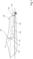
- shows a schematically illustrated marine vessel;
- Figure 2
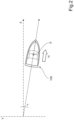
- shows the marine vessel placed in a reference system;
- Figure 3
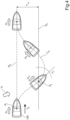
- shows the marine vessel maneuvered according to a first control strategy;
- Figure 4
- shows the marine vessel maneuvered according to a second control strategy;
- Figure 5
- shows a flow chart illustrating a method for controlling the vessel; and
- Figure 6
- shows the method applied on a computer arrangement.
-
Figure 1 shows a side view of a schematically illustratedmarine vessel 100 comprising ahull 101 and a pair ofmarine propulsion units vessel 100. Themarine propulsion units corresponding engine 104 and a transmission 105 (one shown). The example inFigure 1 shows two propulsion units driven by inboard engines. Alternative arrangements includes, for instance, two or more outboard engines, a single propulsion unit combined with a bow thruster 106 (indicated in dashed lines), or two or more azimuthing pods arranged under the hull of the vessel. The engines can of course be replaced by electric motors using battery packs or fuel cells, or engines operated on alternative fuels. According to the disclosure, at least two drive units are required for manoeuvering the vessel. - The
marine propulsion units joystick 110 located at an operating position. Thejoystick 110 is connected to an electronic control unit (ECU) 111 viasuitable wiring 112, whichECU 111 is connected to thedriveline additional wiring 113. Alternative control means includes a graphical user interface (GUI), such as a touch sensitive display, or manual controls comprising throttle levers and a steering wheel. -
Figure 2 shows avessel 100 placed in a reference system which will be referred to in the subsequent text. InFigure 2 , the X-axis indicates a requested direction of travel for the vessel, while the Y-axis indicates a transverse deviation from the X-axis. The X- and Y-axes are indicated in dash-dotted lines. Thevessel 100 inFigure 2 is shown travelling at a heading H away from the X-axis. The current heading follows a course indicated by a dashed line arranged at an angle α from the X-axis and passing through a central coordinate point P of thevessel 100. -
Figure 3 shows the marine vessel being maneuvered according to a first control strategy. The control unit 111 (shown inFigure 1 ) comprises processing circuitry being configured to receive an input from thejoystick 110 indicating a requested vessel direction h1 along a virtual reference line representing a plotted course. Such an input will inherently also indicate a requested vessel speed V1. The processing circuitry in the control unit is configured to detect the operator command indicating a requested vessel direction h1 and to plot a course represented by a reference line R1 for the requested vessel direction h1. The control unit will further control the propulsion units to bring the vessel up to the requested vessel speed V1. The processing circuitry will then monitor if a current vessel heading h2 has deviated from the reference line R1. A deviation can be caused, for instance, by a crosswind A pushing thevessel 100 away from the requested vessel direction h1. According to a first example, the deviation is determined as a distance YL measured in the transverse direction relative to the reference line R1 (seeFig.2 ; Y-axis). A deviation is deemed to have occurred when it is detected that the central coordinate point of the vessel has moved from a first position P1 to a second position P2, wherein the transverse distance YL between the reference line is greater than zero. According to a second example, the deviation is determined as an angle (seeFig.2 ; angle α) between the reference line R1 and the current heading h2 of the vessel. A deviation is deemed to have occurred when it is detected that the angle α1 is greater than zero. Alternatively, the processing circuitry can be arranged to monitor both the transverse distance and the angle. - When a deviation from the reference line R1 is detected, the processing circuitry is configured to detect a value for current vessel speed, which in this example is assumed to be equal to the requested vessel speed V1. This is usually the case when the vessel is only subjected to a crosswind or a cross-current. The current vessel speed V1 is compared to a stored predetermined reference speed value Vref stored in the control unit. In the example shown in
Figure 3 , the current vessel speed V1 is lower than the reference speed value Vref. The control unit will then register that the current vessel speed value is within a low speed interval relative to the reference speed value Vref. Subsequently, the control unit is arranged to control the vessel according the low speed control strategy in order to bring it back to the requested vessel direction h1 along the reference line R1. This may require an initial displacement controlling the drive units to move the vessel to an adjusted vessel heading h3 that is parallel to the reference line R1. The drive units are then controlled to displace the vessel along a diagonal course C1 at the adjusted vessel heading h3 towards the reference line R1. The control unit will control the current vessel speed up or down in order to maintain the requested vessel speed V1 within the low speed interval until the current vessel heading h4 coincides, that is, is parallel with the requested vessel direction h1 on the reference line R1. Preferably, the initially requested vessel speed V1 is maintained while performing the low speed control strategy. The transverse distance and/or the angle are constantly monitored as the vessel is controlled towards the originally requested vessel direction h1 on the reference line R1. -
Figure 4 shows the marine vessel being maneuvered according to a second control strategy. In the same way as described above, the control unit comprises processing circuitry being configured to receive an input from the joystick indicating a requested vessel direction H1 along a virtual reference line representing a plotted course. Such an input will inherently also indicate a requested vessel speed V2. The processing circuitry in the control unit is configured to detect the operator command indicating a requested vessel direction H1 and to plot a course represented by a reference line R2 for the requested vessel direction H1. The control unit will further control the propulsion units to bring the vessel up to the requested vessel speed V2. The processing circuitry will then monitor if a current vessel heading H2 has deviated from the reference line R2. A deviation can be caused, for instance, by a crosswind A pushing thevessel 100 away from the requested vessel direction H1. According to a first example, the deviation is determined as a distance YH measured in the transverse direction relative to the reference line R2 (seeFig.2 ; Y-axis). A deviation is deemed to have occurred when it is detected that the central coordinate point of the vessel has moved from a first position P1 to a second position P2, wherein the transverse distance YH between the reference line is greater than zero. According to a second example, the deviation is determined as an angle (seeFig.4 ; angle α2) between the reference line R2 and the current heading H2 of the vessel. A deviation is deemed to have occurred when it is detected that the angle α2 is greater than zero. Alternatively, the processing circuitry can be arranged to monitor both the transverse distance and the angle. The direction of the deviation relative to the reference line is also determined. - When a deviation from the reference line R2 is detected, the processing circuitry is configured to detect a value for current vessel speed, which in this example is assumed to be equal to the requested vessel speed V2. This is usually the case when the vessel is only subjected to a crosswind or a cross-current. The current vessel speed V2 is compared to a stored predetermined reference speed value Vref stored in the control unit. In the example shown in
Figure 4 , the current vessel speed V2 is higher than the reference speed value Vref. The control unit will then register that the current vessel speed value is within a high speed interval relative to the reference speed value Vref. Subsequently, the control unit is arranged to control the vessel according the high speed control strategy in order to bring it back to the requested vessel direction H1 along the reference line R1. The two or more drive units are controlled by the control unit to steer the vessel along a course C2 turning the vessel from the current vessel heading H2 along a trajectory having a variable heading H3 towards the reference line R2. In this case, the vessel heading is allowed to change during the maneuver, as the maximum available transverse propulsive thrust from the drive units is insufficient for maintaining a heading parallel to the reference line at the current vessel speed. The control unit will maintain the requested vessel speed V2 within the high-speed interval until the current, variable vessel heading H3 coincides with the requested vessel direction H1 on the reference line. Preferably, the initially requested vessel speed V2 is maintained while performing the high-speed control strategy. The transverse distance and/or the angle are constantly monitored as the vessel is controlled to attain the originally requested vessel direction H1 on the reference line R1. -
Figure 5 shows a flow chart illustrating a method for controlling the vessel. The method involves controlling a marine vessel comprising two or more drive units travelling in a straight line on a requested course. In afirst step 501 the method involves registering an operating command indicating a requested vessel direction and vessel speed. The operating command can be an input signal from a joystick, GUI, a helm and throttle lever, or similar transmitted to a control unit. In a second step 502 a course is plotted, which course is represented by a reference line for the requested vessel direction from an initial position. The course is plotted from an initial position represented by the position of the vessel at the time when the operating command is received. The position of the vessel is constantly monitored by a Global Navigation Satellite System (GNSS), e.g. a GPS system or similar. The plotted course is drawn virtually on a digital map stored in a control unit used for controlling the vessel during the execution of the method steps. The course is represented by a reference line passing through a central coordinate point of the vessel and extending in the requested vessel direction. The reference line is stored and maintained for the duration of the requested maneuver. The vessel heading can also be monitored by the GNSS, or alternatively by a suitable compass. - In a
third step 503, the method involves monitoring if the vessel has deviated from the reference line. According to a first example this step involves detecting if a current vessel position has deviated in the transverse distance from the reference line. The transverse distance is measured at right angles from the reference line plotted on the digital map to a position represented by the central coordinate point of the vessel. According to a second example, the method involves monitoring if the current vessel heading has deviated at an angle away from the requested vessel direction. The angle is measured from the reference line plotted on the digital map to line represented by the current vessel heading. Alternatively, both the distance and the angle can be monitored. - In a
fourth step 504 it is determined if a deviation of the vessel from the reference line has occurred -. The deviation is determined by monitoring if a current vessel position has deviated a transverse distance from the reference line. Alternatively, the deviation is determined by monitoring if the current vessel heading has deviated an angle from the requested vessel direction. If it is determined that a deviation has not occurred, the method proceeds to afifth step 505 where the control unit checks if the straight-line operating command is still valid. If the operating command has been cancelled, then the process is ended in asixth step 506. If the operating command is maintained, then the process returns to thethird step 503 and continues monitoring the transverse distance or the angle during the progress of the vessel. According to an alternative example, the method can involve monitoring both the transverse distance and the angle. - If it is determined that a deviation has occurred, the method proceeds to a
seventh step 507 where the control unit detects a value for current vessel speed. In an eightstep 508 the method compares the detected vessel speed value to a predetermined reference speed value. The predetermined reference speed value used for this step is also dependent on the direction of travel of the vessel. Depending on the outcome of the comparison, the method registers if the current vessel speed value is within a high speed interval or a low speed interval relative to the reference speed value. - If the current vessel speed value is equal to or below the stored reference speed value, then a low speed control strategy is selected and registered. The method then proceeds to a
ninth step 509 wherein the vessel is controlled according to a low speed control strategy in order to move the vessel from a current vessel heading towards the stored reference line and to resume the requested vessel direction. In this case, the method involves monitoring the deviation and adjusting the current vessel heading, if necessary, and maintaining an adjusted vessel heading parallel to the reference line and the requested vessel direction. Subsequently, the two or more drive units are controlled to displace the vessel along a diagonal course at the adjusted vessel heading towards the reference line. The current vessel speed is maintained within the low speed interval while the vessel is displaced towards the requested vessel direction on the reference line. Preferably, the initially requested vessel speed is maintained while performing the low speed control strategy. In atenth step 510 the method checks whether the straight-line operating command has been cancelled or not. If this is not the case, then the method returns to theninth step 509 for continued monitoring of the deviation and control of the vessel towards the reference line. If the straight-line operating command has been cancelled, then the process is ended in athirteenth step 513. - If the current vessel speed value is above the stored reference speed value, then a high-speed control strategy is selected and registered. The method then proceeds to an
eleventh step 511 wherein the vessel is controlled according to a high speed control strategy in order to move the vessel from a current vessel heading to the stored reference line and to resume the requested vessel direction. In this case, the method involves monitoring the deviation and determining heading adjustments required for reaching the reference line and the requested vessel direction. Subsequently, the two or more drive units are controlled to steer the vessel along a course from the current vessel heading along a variable heading towards the reference line. In this case, the vessel heading is allowed to change during the maneuver. The current vessel speed is maintained within the high-speed interval while the current vessel heading changes towards the requested vessel direction on the reference line. Preferably, the initially requested vessel speed is maintained while performing the high speed control strategy. In atwelfth step 512 the method checks whether the straight-line operating command has been cancelled or not. If this is not the case, then the method returns to theeleventh step 511 for continued monitoring of the deviation and control of the vessel towards the reference line. If the straight-line operating command has been cancelled, then the process is ended in athirteenth step 513. - The present disclosure also relates to a computer program, and a computer program product to be used with a computer for executing the method as described in any one of the above examples.
Figure 6 shows the method described in connection withFigure 5 applied on a computer arrangement. -
Figure 6 shows anapparatus 600 according to the present disclosure, comprising anon-volatile memory 620, aprocessor 610 and a read-write memory 660. Thememory 620 has afirst memory part 630, in which a computer program for controlling theapparatus 600 is stored. The computer program in thememory part 630 for controlling theapparatus 600 can be an operating system. Theapparatus 600 can be enclosed in, for example, a control unit, such as thecontrol unit 111 inFigure 1 . The data-processing unit 610 can comprise, for example, a microcomputer. Thememory 620 also has asecond memory part 640, in which a program for controlling the marine vessel travelling in a selected straight line in a forward or backward direction according to the invention is stored. In an alternative embodiment, the program for controlling the marine vessel is stored in a separatenon-volatile storage medium 650 for data, such as, for example, a CD or an exchangeable semiconductor memory. The program can be stored in an executable form or in a compressed state. - When it is stated below that the data-
processing unit 610 runs a specific function, it should be clear that the data-processing unit 610 is running a specific part of the program stored in thememory 640 or a specific part of the program stored in thenon-volatile storage medium 650. The data-processing unit 610 is tailored for communication with thestorage memory 650 through adata bus 614. The data-processing unit 610 is also tailored for communication with thememory 620 through adata bus 612. In addition, the data-processing unit 610 is tailored for communication with thememory 660 through adata bus 611. The data-processing unit 610 is also tailored for communication with adata port 690 by the use of adata bus 615. - The method according to the present disclosure can be executed by the data-
processing unit 610, by the data-processing unit 610 running the program stored in thememory 640 or the program stored in thenon-volatile storage medium 650. - The present disclosure should not be deemed to be limited to the embodiments described above, but rather a number of further variants and modifications are conceivable within the scope of the following patent claims.
Claims (13)
- A method to control a marine vessel (100) comprising two or more drive units (102, 103); the method involving the steps of:- registering an operating command indicating a requested vessel direction (h1; H1);- plotting a course represented by a reference line (R1; R2) for the requested vessel direction (h1; H1) from an initial position (p1; P1);- monitoring if the vessel has deviated from the reference line (R1; R2); and if a deviation from the reference line (R1; R2) is detected;- detecting a value for current vessel speed (V1; V2);- comparing the current vessel speed value (V1; V2) to a predetermined reference speed value (Vref);- registering if the current vessel speed value (V1; V2) is within a high speed interval or a low speed interval relative to the reference speed value (Vref), and depending on the registered speed interval;i) controlling the vessel according to a low speed control strategy; orii) controlling the vessel according to a high speed control strategy;in order to move the vessel from a current vessel heading (h2; H2) to the reference line (R1; R2) and the requested vessel direction (h1; H1),characterized in that said controlling of the vessel according to a low speed control strategy comprises:- adjusting the current vessel heading (h2) and maintaining an adjusted vessel heading (h3) parallel to the reference line (R1) and the requested vessel direction (h1); and- controlling the two or more drive units (102, 103) to displace the vessel (100) along a diagonal course (C1) at the adjusted vessel heading (h3) towards the reference line (R1).
- The method according to claim 1, involving monitoring if a current vessel position (p2; P2) has deviated from the reference line (R1; R2) in the transverse direction (YL; YH).
- The method according to claim 1 or 2, involving monitoring if the current vessel heading (h2; H2) has deviated from the requested vessel direction (h1; H1).
- The method according to any one of claims 1-3, involving registering the requested vessel direction (h1; H1) in response to an input signal from a joystick.
- The method according to any one of claims 1-3, involving registering the requested vessel direction (h1; H1) in response to an input signal from a graphical user interface.
- The method according to any one of claims 1-3, involving registering the requested vessel direction (h1; H1) in response to an input signal indicating auto-pilot actuation (from a throttle and a helm).
- The method according to any one of claims 1-6, involving maintaining the current vessel speed within the low speed interval until the current vessel heading coincides with the requested vessel direction (h1) on the reference line (R1).
- The method according to any one of the above claims 1-7, wherein the deviation from the reference line (R1; R2) is detected by a Global Navigation Satellite System.
- The method according to any one of the above claims 1-8, wherein the vessel heading is determined by a compass or a Global Navigation Satellite System.
- A control unit (111; 640) arranged to control a marine vessel (100) during straight line travel, the vessel (100) comprising two or more drive units (102, 103), the control unit (111; 640) comprising processing circuitry, the processing circuitry being configured to receive an input indicating a requested vessel direction (h1; H1) along a reference line (R1; R2) representing a plotted course, whereinthe processing circuitry is configured to:- detect an operator command indicating a requested vessel direction (h1; H1);- plot a course represented by a reference line (R1; R2) for the requested vessel direction (h1; H1);- monitor if the vessel (h2; H2) has deviated from the reference line (R1; R2);and if a deviation from the reference line (R1; R2) is detected, the processing circuitry is further configured to:- detect a value for current vessel speed (V1; V2);- compare the current vessel speed value (V1; V2) to a predetermined reference speed value (Vref);- register if the current vessel speed value (V1; V2) is within a high speed interval or a low speed interval relative to the reference speed value (Vref), and depending of the registered speed interval;i) control the vessel according a low speed control strategy; orii) control the vessel according a high speed control strategy;in order to move the vessel (100) from the current vessel heading (h2; H2) to the reference line (R1; R2) for the requested vessel direction (h1; H1),characterized in thatsaid controlling of the vessel according to a low speed control strategy comprises:- adjusting the current vessel heading (h2) and maintaining an adjusted vessel heading (h3) parallel to the reference line (R1) and the requested vessel direction (h1); and- controlling the two or more drive units (102, 103) to displace the vessel (100) along a diagonal course (C1) at the adjusted vessel heading (h3) towards the reference line (R1).
- Marine vessel, wherein the marine vessel (100) comprises a control unit (111, 640) according to claim 10.
- A computer program comprising program code means for performing the method according to claim 1 when said program is run on a computer.
- A computer program product comprising program code means stored on a computer readable medium for performing the method according to claim 1 when said program product is run on a computer.
Applications Claiming Priority (1)
| Application Number | Priority Date | Filing Date | Title |
|---|---|---|---|
| PCT/EP2020/064033 WO2021233532A1 (en) | 2020-05-20 | 2020-05-20 | Method to control a marine vessel, a control unit and a vessel |
Publications (3)
| Publication Number | Publication Date |
|---|---|
| EP4154080A1 EP4154080A1 (en) | 2023-03-29 |
| EP4154080C0 EP4154080C0 (en) | 2024-07-03 |
| EP4154080B1 true EP4154080B1 (en) | 2024-07-03 |
Family
ID=70847356
Family Applications (1)
| Application Number | Title | Priority Date | Filing Date |
|---|---|---|---|
| EP20727968.8A Active EP4154080B1 (en) | 2020-05-20 | 2020-05-20 | Method to control a marine vessel, a control unit and a vessel |
Country Status (4)
| Country | Link |
|---|---|
| US (1) | US12346114B2 (en) |
| EP (1) | EP4154080B1 (en) |
| CN (1) | CN115668087A (en) |
| WO (1) | WO2021233532A1 (en) |
Families Citing this family (1)
| Publication number | Priority date | Publication date | Assignee | Title |
|---|---|---|---|---|
| US10671073B2 (en) * | 2017-02-15 | 2020-06-02 | Brunswick Corporation | Station keeping system and method |
Family Cites Families (10)
| Publication number | Priority date | Publication date | Assignee | Title |
|---|---|---|---|---|
| US20030150366A1 (en) | 2002-02-13 | 2003-08-14 | Kaufmann Timothy W. | Watercraft steer-by-wire system |
| WO2007055605A1 (en) * | 2005-11-12 | 2007-05-18 | Cwf Hamilton & Co Limited | Propulsion and control system for a marine vessel |
| CN102323820A (en) * | 2011-04-19 | 2012-01-18 | 江苏科技大学 | Intelligent rudder system and control method thereof |
| CN105122166B (en) | 2013-01-31 | 2017-09-19 | 菲力尔系统公司 | Stabilized directional control system and method |
| EP2952994A1 (en) * | 2014-06-03 | 2015-12-09 | GE Energy Power Conversion Technology Ltd | System and method for dynamic positioning |
| JP6479418B2 (en) * | 2014-10-31 | 2019-03-06 | 古野電気株式会社 | Remote steering system, remote control device, and remote steering method |
| US10259555B2 (en) * | 2016-08-25 | 2019-04-16 | Brunswick Corporation | Methods for controlling movement of a marine vessel near an object |
| WO2019011445A1 (en) * | 2017-07-14 | 2019-01-17 | Volvo Penta Corporation | A marine vessel propulsion unit calibration method |
| SG11202011726WA (en) | 2018-06-01 | 2020-12-30 | Waertsilae Sam Electronics Gmbh | Method, device and apparatus for autonomous docking of marine vessel |
| US11675372B2 (en) * | 2019-08-08 | 2023-06-13 | Brunswick Corporation | Method and system for controlling attitude of a marine vessel |
-
2020
- 2020-05-20 US US17/999,283 patent/US12346114B2/en active Active
- 2020-05-20 EP EP20727968.8A patent/EP4154080B1/en active Active
- 2020-05-20 WO PCT/EP2020/064033 patent/WO2021233532A1/en not_active Ceased
- 2020-05-20 CN CN202080100859.3A patent/CN115668087A/en active Pending
Also Published As
| Publication number | Publication date |
|---|---|
| EP4154080C0 (en) | 2024-07-03 |
| WO2021233532A1 (en) | 2021-11-25 |
| US20230195117A1 (en) | 2023-06-22 |
| CN115668087A (en) | 2023-01-31 |
| US12346114B2 (en) | 2025-07-01 |
| EP4154080A1 (en) | 2023-03-29 |
Similar Documents
| Publication | Publication Date | Title |
|---|---|---|
| EP3210878B1 (en) | Vessel steering apparatus | |
| US10640190B1 (en) | System and method for controlling course of a marine vessel | |
| EP1981757B1 (en) | A method and arrangement for controlling a drive arrangement in a watercraft | |
| JP7249657B2 (en) | Vessel control method | |
| EP3464057B1 (en) | Method and control apparatus for operating a marine vessel | |
| EP3406516B1 (en) | Ship maneuvering device and ship provided therewith | |
| US20250153838A1 (en) | Uniaxial twin-rudder ship having automatic docking function | |
| WO2020069750A1 (en) | Thruster assisted docking | |
| JP7664060B2 (en) | Navigation equipment and vessel | |
| EP4389589B1 (en) | Steering system having function of correcting steering angle of uniaxial two-rudder vessel | |
| US20080269968A1 (en) | Watercraft position management system & method | |
| EP4227209B1 (en) | Watercraft control system and watercraft control method | |
| US20240152146A1 (en) | Watercraft propulsion system, and watercraft including the watercraft propulsion system | |
| JP7573296B2 (en) | Ship motion control device for single-propeller, twin-rudder ships | |
| EP4154079B1 (en) | Control method and control unit for a marine vessel | |
| US12346114B2 (en) | Method to control a marine vessel, a control unit and a vessel | |
| US12466530B2 (en) | Watercraft propulsion system, and watercraft including the watercraft propulsion system | |
| US20240149999A1 (en) | Watercraft propulsion system, and watercraft including the watercraft propulsion system | |
| JP7598653B2 (en) | Positioning system for single-propeller, twin-rudder ships | |
| EP4632521B1 (en) | Autopilot control of a marine vessel |
Legal Events
| Date | Code | Title | Description |
|---|---|---|---|
| STAA | Information on the status of an ep patent application or granted ep patent |
Free format text: STATUS: UNKNOWN |
|
| STAA | Information on the status of an ep patent application or granted ep patent |
Free format text: STATUS: THE INTERNATIONAL PUBLICATION HAS BEEN MADE |
|
| PUAI | Public reference made under article 153(3) epc to a published international application that has entered the european phase |
Free format text: ORIGINAL CODE: 0009012 |
|
| STAA | Information on the status of an ep patent application or granted ep patent |
Free format text: STATUS: REQUEST FOR EXAMINATION WAS MADE |
|
| 17P | Request for examination filed |
Effective date: 20221124 |
|
| AK | Designated contracting states |
Kind code of ref document: A1 Designated state(s): AL AT BE BG CH CY CZ DE DK EE ES FI FR GB GR HR HU IE IS IT LI LT LU LV MC MK MT NL NO PL PT RO RS SE SI SK SM TR |
|
| DAV | Request for validation of the european patent (deleted) | ||
| DAX | Request for extension of the european patent (deleted) | ||
| GRAP | Despatch of communication of intention to grant a patent |
Free format text: ORIGINAL CODE: EPIDOSNIGR1 |
|
| REG | Reference to a national code |
Ref country code: DE Free format text: PREVIOUS MAIN CLASS: G05D0001020000 Ipc: G05D0001646000 Ref country code: DE Ref legal event code: R079 Ref document number: 602020033322 Country of ref document: DE Free format text: PREVIOUS MAIN CLASS: G05D0001020000 Ipc: G05D0001646000 |
|
| STAA | Information on the status of an ep patent application or granted ep patent |
Free format text: STATUS: GRANT OF PATENT IS INTENDED |
|
| INTG | Intention to grant announced |
Effective date: 20240111 |
|
| RIC1 | Information provided on ipc code assigned before grant |
Ipc: G05D 109/30 20240101ALI20240110BHEP Ipc: G05D 1/646 20240101AFI20240110BHEP |
|
| GRAS | Grant fee paid |
Free format text: ORIGINAL CODE: EPIDOSNIGR3 |
|
| GRAA | (expected) grant |
Free format text: ORIGINAL CODE: 0009210 |
|
| STAA | Information on the status of an ep patent application or granted ep patent |
Free format text: STATUS: THE PATENT HAS BEEN GRANTED |
|
| AK | Designated contracting states |
Kind code of ref document: B1 Designated state(s): AL AT BE BG CH CY CZ DE DK EE ES FI FR GB GR HR HU IE IS IT LI LT LU LV MC MK MT NL NO PL PT RO RS SE SI SK SM TR |
|
| REG | Reference to a national code |
Ref country code: CH Ref legal event code: EP |
|
| REG | Reference to a national code |
Ref country code: DE Ref legal event code: R096 Ref document number: 602020033322 Country of ref document: DE |
|
| U01 | Request for unitary effect filed |
Effective date: 20240716 |
|
| U07 | Unitary effect registered |
Designated state(s): AT BE BG DE DK EE FI FR IT LT LU LV MT NL PT SE SI Effective date: 20240729 |
|
| PG25 | Lapsed in a contracting state [announced via postgrant information from national office to epo] |
Ref country code: NO Free format text: LAPSE BECAUSE OF FAILURE TO SUBMIT A TRANSLATION OF THE DESCRIPTION OR TO PAY THE FEE WITHIN THE PRESCRIBED TIME-LIMIT Effective date: 20241003 |
|
| PG25 | Lapsed in a contracting state [announced via postgrant information from national office to epo] |
Ref country code: GR Free format text: LAPSE BECAUSE OF FAILURE TO SUBMIT A TRANSLATION OF THE DESCRIPTION OR TO PAY THE FEE WITHIN THE PRESCRIBED TIME-LIMIT Effective date: 20241004 Ref country code: PL Free format text: LAPSE BECAUSE OF FAILURE TO SUBMIT A TRANSLATION OF THE DESCRIPTION OR TO PAY THE FEE WITHIN THE PRESCRIBED TIME-LIMIT Effective date: 20240703 |
|
| PG25 | Lapsed in a contracting state [announced via postgrant information from national office to epo] |
Ref country code: IS Free format text: LAPSE BECAUSE OF FAILURE TO SUBMIT A TRANSLATION OF THE DESCRIPTION OR TO PAY THE FEE WITHIN THE PRESCRIBED TIME-LIMIT Effective date: 20241103 |
|
| PG25 | Lapsed in a contracting state [announced via postgrant information from national office to epo] |
Ref country code: HR Free format text: LAPSE BECAUSE OF FAILURE TO SUBMIT A TRANSLATION OF THE DESCRIPTION OR TO PAY THE FEE WITHIN THE PRESCRIBED TIME-LIMIT Effective date: 20240703 Ref country code: CZ Free format text: LAPSE BECAUSE OF FAILURE TO SUBMIT A TRANSLATION OF THE DESCRIPTION OR TO PAY THE FEE WITHIN THE PRESCRIBED TIME-LIMIT Effective date: 20240703 |
|
| PG25 | Lapsed in a contracting state [announced via postgrant information from national office to epo] |
Ref country code: RS Free format text: LAPSE BECAUSE OF FAILURE TO SUBMIT A TRANSLATION OF THE DESCRIPTION OR TO PAY THE FEE WITHIN THE PRESCRIBED TIME-LIMIT Effective date: 20241003 Ref country code: ES Free format text: LAPSE BECAUSE OF FAILURE TO SUBMIT A TRANSLATION OF THE DESCRIPTION OR TO PAY THE FEE WITHIN THE PRESCRIBED TIME-LIMIT Effective date: 20240703 |
|
| PG25 | Lapsed in a contracting state [announced via postgrant information from national office to epo] |
Ref country code: RS Free format text: LAPSE BECAUSE OF FAILURE TO SUBMIT A TRANSLATION OF THE DESCRIPTION OR TO PAY THE FEE WITHIN THE PRESCRIBED TIME-LIMIT Effective date: 20241003 Ref country code: PL Free format text: LAPSE BECAUSE OF FAILURE TO SUBMIT A TRANSLATION OF THE DESCRIPTION OR TO PAY THE FEE WITHIN THE PRESCRIBED TIME-LIMIT Effective date: 20240703 Ref country code: NO Free format text: LAPSE BECAUSE OF FAILURE TO SUBMIT A TRANSLATION OF THE DESCRIPTION OR TO PAY THE FEE WITHIN THE PRESCRIBED TIME-LIMIT Effective date: 20241003 Ref country code: IS Free format text: LAPSE BECAUSE OF FAILURE TO SUBMIT A TRANSLATION OF THE DESCRIPTION OR TO PAY THE FEE WITHIN THE PRESCRIBED TIME-LIMIT Effective date: 20241103 Ref country code: HR Free format text: LAPSE BECAUSE OF FAILURE TO SUBMIT A TRANSLATION OF THE DESCRIPTION OR TO PAY THE FEE WITHIN THE PRESCRIBED TIME-LIMIT Effective date: 20240703 Ref country code: GR Free format text: LAPSE BECAUSE OF FAILURE TO SUBMIT A TRANSLATION OF THE DESCRIPTION OR TO PAY THE FEE WITHIN THE PRESCRIBED TIME-LIMIT Effective date: 20241004 Ref country code: ES Free format text: LAPSE BECAUSE OF FAILURE TO SUBMIT A TRANSLATION OF THE DESCRIPTION OR TO PAY THE FEE WITHIN THE PRESCRIBED TIME-LIMIT Effective date: 20240703 Ref country code: CZ Free format text: LAPSE BECAUSE OF FAILURE TO SUBMIT A TRANSLATION OF THE DESCRIPTION OR TO PAY THE FEE WITHIN THE PRESCRIBED TIME-LIMIT Effective date: 20240703 |
|
| PG25 | Lapsed in a contracting state [announced via postgrant information from national office to epo] |
Ref country code: SM Free format text: LAPSE BECAUSE OF FAILURE TO SUBMIT A TRANSLATION OF THE DESCRIPTION OR TO PAY THE FEE WITHIN THE PRESCRIBED TIME-LIMIT Effective date: 20240703 |
|
| PG25 | Lapsed in a contracting state [announced via postgrant information from national office to epo] |
Ref country code: SK Free format text: LAPSE BECAUSE OF FAILURE TO SUBMIT A TRANSLATION OF THE DESCRIPTION OR TO PAY THE FEE WITHIN THE PRESCRIBED TIME-LIMIT Effective date: 20240703 |
|
| PLBE | No opposition filed within time limit |
Free format text: ORIGINAL CODE: 0009261 |
|
| STAA | Information on the status of an ep patent application or granted ep patent |
Free format text: STATUS: NO OPPOSITION FILED WITHIN TIME LIMIT |
|
| 26N | No opposition filed |
Effective date: 20250404 |
|
| U20 | Renewal fee for the european patent with unitary effect paid |
Year of fee payment: 6 Effective date: 20250526 |
|
| PGFP | Annual fee paid to national office [announced via postgrant information from national office to epo] |
Ref country code: GB Payment date: 20250520 Year of fee payment: 6 |
|
| REG | Reference to a national code |
Ref country code: CH Ref legal event code: H13 Free format text: ST27 STATUS EVENT CODE: U-0-0-H10-H13 (AS PROVIDED BY THE NATIONAL OFFICE) Effective date: 20251223 |
|
| PG25 | Lapsed in a contracting state [announced via postgrant information from national office to epo] |
Ref country code: CH Free format text: LAPSE BECAUSE OF NON-PAYMENT OF DUE FEES Effective date: 20250531 |
|
| PG25 | Lapsed in a contracting state [announced via postgrant information from national office to epo] |
Ref country code: MC Free format text: LAPSE BECAUSE OF FAILURE TO SUBMIT A TRANSLATION OF THE DESCRIPTION OR TO PAY THE FEE WITHIN THE PRESCRIBED TIME-LIMIT Effective date: 20240703 |
|
| PG25 | Lapsed in a contracting state [announced via postgrant information from national office to epo] |
Ref country code: IE Free format text: LAPSE BECAUSE OF NON-PAYMENT OF DUE FEES Effective date: 20250520 |
|
| PG25 | Lapsed in a contracting state [announced via postgrant information from national office to epo] |
Ref country code: RO Free format text: LAPSE BECAUSE OF FAILURE TO SUBMIT A TRANSLATION OF THE DESCRIPTION OR TO PAY THE FEE WITHIN THE PRESCRIBED TIME-LIMIT Effective date: 20240703 |