EP4154079B1 - Control method and control unit for a marine vessel - Google Patents
Control method and control unit for a marine vessel Download PDFInfo
- Publication number
- EP4154079B1 EP4154079B1 EP20727969.6A EP20727969A EP4154079B1 EP 4154079 B1 EP4154079 B1 EP 4154079B1 EP 20727969 A EP20727969 A EP 20727969A EP 4154079 B1 EP4154079 B1 EP 4154079B1
- Authority
- EP
- European Patent Office
- Prior art keywords
- vessel
- bollard
- vessel position
- requested
- current
- Prior art date
- Legal status (The legal status is an assumption and is not a legal conclusion. Google has not performed a legal analysis and makes no representation as to the accuracy of the status listed.)
- Active
Links
Images




Classifications
-
- G—PHYSICS
- G05—CONTROLLING; REGULATING
- G05D—SYSTEMS FOR CONTROLLING OR REGULATING NON-ELECTRIC VARIABLES
- G05D1/00—Control of position, course, altitude or attitude of land, water, air or space vehicles, e.g. using automatic pilots
- G05D1/02—Control of position or course in two dimensions
- G05D1/0206—Control of position or course in two dimensions specially adapted to water vehicles
- G05D1/0208—Control of position or course in two dimensions specially adapted to water vehicles dynamic anchoring
-
- G—PHYSICS
- G05—CONTROLLING; REGULATING
- G05D—SYSTEMS FOR CONTROLLING OR REGULATING NON-ELECTRIC VARIABLES
- G05D1/00—Control of position, course, altitude or attitude of land, water, air or space vehicles, e.g. using automatic pilots
- G05D1/02—Control of position or course in two dimensions
- G05D1/0206—Control of position or course in two dimensions specially adapted to water vehicles
-
- B—PERFORMING OPERATIONS; TRANSPORTING
- B63—SHIPS OR OTHER WATERBORNE VESSELS; RELATED EQUIPMENT
- B63B—SHIPS OR OTHER WATERBORNE VESSELS; EQUIPMENT FOR SHIPPING
- B63B79/00—Monitoring properties or operating parameters of vessels in operation
- B63B79/10—Monitoring properties or operating parameters of vessels in operation using sensors, e.g. pressure sensors, strain gauges or accelerometers
-
- B—PERFORMING OPERATIONS; TRANSPORTING
- B63—SHIPS OR OTHER WATERBORNE VESSELS; RELATED EQUIPMENT
- B63H—MARINE PROPULSION OR STEERING
- B63H20/00—Outboard propulsion units, e.g. outboard motors or Z-drives; Arrangements thereof on vessels
-
- B—PERFORMING OPERATIONS; TRANSPORTING
- B63—SHIPS OR OTHER WATERBORNE VESSELS; RELATED EQUIPMENT
- B63H—MARINE PROPULSION OR STEERING
- B63H21/00—Use of propulsion power plant or units on vessels
- B63H21/21—Control means for engine or transmission, specially adapted for use on marine vessels
- B63H21/213—Levers or the like for controlling the engine or the transmission, e.g. single hand control levers
-
- B—PERFORMING OPERATIONS; TRANSPORTING
- B63—SHIPS OR OTHER WATERBORNE VESSELS; RELATED EQUIPMENT
- B63H—MARINE PROPULSION OR STEERING
- B63H25/00—Steering; Slowing-down otherwise than by use of propulsive elements; Dynamic anchoring, i.e. positioning vessels by means of main or auxiliary propulsive elements
- B63H25/02—Initiating means for steering, for slowing down, otherwise than by use of propulsive elements, or for dynamic anchoring
- B63H25/04—Initiating means for steering, for slowing down, otherwise than by use of propulsive elements, or for dynamic anchoring automatic, e.g. reacting to compass
-
- B—PERFORMING OPERATIONS; TRANSPORTING
- B63—SHIPS OR OTHER WATERBORNE VESSELS; RELATED EQUIPMENT
- B63H—MARINE PROPULSION OR STEERING
- B63H25/00—Steering; Slowing-down otherwise than by use of propulsive elements; Dynamic anchoring, i.e. positioning vessels by means of main or auxiliary propulsive elements
- B63H25/42—Steering or dynamic anchoring by propulsive elements; Steering or dynamic anchoring by propellers used therefor only; Steering or dynamic anchoring by rudders carrying propellers
-
- G—PHYSICS
- G05—CONTROLLING; REGULATING
- G05D—SYSTEMS FOR CONTROLLING OR REGULATING NON-ELECTRIC VARIABLES
- G05D1/00—Control of position, course, altitude or attitude of land, water, air or space vehicles, e.g. using automatic pilots
- G05D1/40—Control within particular dimensions
- G05D1/43—Control of position or course in two dimensions [2D]
-
- B—PERFORMING OPERATIONS; TRANSPORTING
- B63—SHIPS OR OTHER WATERBORNE VESSELS; RELATED EQUIPMENT
- B63B—SHIPS OR OTHER WATERBORNE VESSELS; EQUIPMENT FOR SHIPPING
- B63B2213/00—Navigational aids and use thereof, not otherwise provided for in this class
- B63B2213/02—Navigational aids and use thereof, not otherwise provided for in this class using satellite radio beacon positioning systems, e.g. the Global Positioning System GPS
-
- B—PERFORMING OPERATIONS; TRANSPORTING
- B63—SHIPS OR OTHER WATERBORNE VESSELS; RELATED EQUIPMENT
- B63H—MARINE PROPULSION OR STEERING
- B63H21/00—Use of propulsion power plant or units on vessels
- B63H21/21—Control means for engine or transmission, specially adapted for use on marine vessels
- B63H2021/216—Control means for engine or transmission, specially adapted for use on marine vessels using electric control means
-
- G—PHYSICS
- G05—CONTROLLING; REGULATING
- G05D—SYSTEMS FOR CONTROLLING OR REGULATING NON-ELECTRIC VARIABLES
- G05D2109/00—Types of controlled vehicles
- G05D2109/30—Water vehicles
Definitions
- a vessel may be required to perform a docking manoeuvre where the vessel is not moored, but merely held against the side of a dock using the propulsion system.
- This manoeuvre can be generally referred to as a "bollard push manoeuvre" as the drive units making up the propulsion system are being operated while the vessel is held in position with its bow or side being forced against the side of a dock.
- the vessel When performing a bollard push manoeuvre, the vessel is supposed to stay in place with its side or bow being held against the dock by the thrust from the propulsion system. This manoeuvre can be used for allowing passengers to board or disembark without having to tie the vessel up in a mooring position.
- a problem with this manoeuvre is that the vessel can start moving from its originally intended position due to external factors. Examples of such external factors can be a sudden burst of wind, an unexpected water current or a movement of the dock itself. Under such conditions the vessel can suddenly drift off in an unexpected direction, potentially resulting in a dangerous situation.
- a further problem is that an operator detecting an unexpected vessel movement may try to correct for the displacement by operating the direction and magnitude of the thrust of the propulsion system, If this operation is not performed swiftly and/or correctly the dangerous situation will not be corrected.
- JP 2019 162977 A relates to an automatic maneuvering system that includes: a control system for controlling driving of a maneuvering device; a way point setting means for setting a way point as a target value; a sensor for grasping a vessel position and a bow direction; and a sensor set of an anemometer for detecting turbulence affecting hull motion, a high accuracy GPS for monitoring hull motion or the surrounding state more accurately, an oscillation meter, a rider, and a camera, etc.
- the automatic maneuvering system predicts change in disturbance from the detected disturbance.
- WO 2019/231464 A1 relates to an apparatus and a computer-implemented method for autonomous marine vessel docking, the method comprising: determining a transit control mode associated with route plan data defining transit operation between ports; determining an autonomous docking control mode associated with harbor track data comprising a set of waypoint properties and defining approach zone information and track segments joined at waypoints. Method further comprises determining vessel location, speed and heading; comparing the vessel location, speed and heading to the approach zone information and changing from the transit control mode to the autonomous docking control mode in response to: the vessel location comprised by the location area information; the vessel speed being lower than the maximum vessel speed for entering the approach zone; and the vessel heading matching criteria defined by the maximum heading deviation for entering the approach zone.
- the terms "vessel heading” or “heading” are intended to describe the direction of the longitudinal axis of the vessel in or relative to the normal direction of travel.
- the normal direction of travel is usually the forward direction, in which case the heading is the direction in which the bow of the vessels is pointing.
- the term “drive unit” is used to denote both main propulsion units and bow or lateral thrusters.
- Lateral thrusters are usually provided for assisting displacement of the vessel in a transverse or diagonal direction when only a single main propulsion unit is provided or if the main propulsion units cannot be maneuvered to provide a sufficient transverse thrust.
- a minimum of two drive units is required.
- the minimum requirement is a vessel having a single propulsion unit and a single bow thruster or a vessel having a minimum of two main propulsion units.
- the manoeuvre being performed by a vessel performing the claimed method will be referred to as a "bollard push manoeuvre", during which manoeuvre the drive units making up the propulsion system will remain operational.
- a vessel being held with its bow against the dock will be described as performing a "bow bollard push”.
- a vessel being held with its side against the dock will be described as performing a "sideways bollard push”.
- a vessel having this capability will be described as having a bollard push function.
- the requested bollard push function is automatically deactivated.
- the method involves monitoring if the deviation of a current vessel position relative to the desired vessel position has exceeded a predetermined distance.
- the vessel is placed alongside a dock when sideways bollard push manoeuvre is being performed, then the drive units will provide a transverse thrust to maintain the side of the vessel in contact with the dock.
- a displacement in the transverse and/or the longitudinal direction of the vessel is constantly monitored. If the vessel is suddenly displaced away from or along the dock, then the requested bollard push function is deactivated.
- the method involves monitoring if the deviation of a current vessel heading relative to the desired vessel heading has exceeded a predetermined angle.
- the vessel is placed with its bow against a dock when a bow bollard push manoeuvre is being performed, then the drive units will provide a thrust substantially in the longitudinal direction to maintain the bow of the vessel in contact with the dock.
- an angular displacement of the vessel where the bow is a pivot point, is constantly monitored. If the vessel is suddenly displaced a predetermined angle away from the initial vessel position against the dock, then the requested bollard push function is deactivated.
- the method according to this example can be combined with that described in the first example above, to cover both angular and linear displacements. For instance, if the vessel is displaced in its longitudinal direction only, then this would not cause a change in the heading. However, the function would still be deactivated if the predetermined distance is exceeded.
- the method involves monitoring if the rate of change of the deviation for a current vessel position relative to the desired vessel position has exceeded a predetermined value. For instance, if the vessel is placed with its side or bow against a dock when the bollard push manoeuvre is being performed, then the drive units will provide a suitable thrust to maintain the side or the bow of the vessel in contact with the dock. During the manoeuvre, any angular or linear displacement of the vessel is constantly monitored. If the vessel is displaced linearly or angularly away from the initial vessel position against the dock at a rate that exceeds a predetermined rate of change, then the requested bollard push function is deactivated.
- Monitoring of the bollard push function can be performed using any one of the above monitoring methods, alone or in combination.
- the drive units will provide a requested or predetermined thrust having a suitable magnitude and direction to maintain a selected portion of the vessel in contact with the dock or a similar fixed structure.
- a relatively limited amount of thrust will be sufficient for achieving this, wherein the drive units can be operated a relatively low speed, such as at or near their idling speeds.
- An operating command indicating that a bollard push function is requested can be registered in response to an input signal from a joystick, a graphical user interface (GUI) or to input signals from at least one throttle controller and a helm controller, optionally in combination with a switch.
- GUI graphical user interface
- the method involves at least disengaging the drive units when deactivating the requested bollard push function.
- the method can optionally involve the further steps of registering an updated current vessel position and executing a position hold function in order to maintain the updated current vessel position.
- the updated current vessel position can be the position of the vessel at the time when the requested bollard push function is deactivated and/or the thrust from the drive units is inhibited. At this time the drive units are not providing any thrust.
- ICE drive units can be disengaged by switching them into a neutral gear and maintained idling, while electric drive units can be switched off. Once the current vessel position is updated the vessel will execute a position hold function in order to maintain that position.
- the vessel position is preferably determined by a Global Navigation Satellite System (GNSS) with a suitable accuracy, such as a Differential Global Positioning System (DGPS).
- GNSS Global Navigation Satellite System
- DGPS Differential Global Positioning System
- control unit arranged to control a marine vessel comprising two or more propulsion units.
- the control unit comprises processing circuitry which is configured to receive an input indicating a requested vessel function.
- processing circuitry is configured to:
- processing circuitry is further configured to:
- the disclosure relates to a marine vessel, wherein the marine vessel comprises a control unit as described above.
- the disclosure relates to a computer program comprising program code means for performing the above-mentioned method when said program is run on a computer.
- the disclosure also relates to a computer program product comprising program code means stored on a computer readable medium for performing the above-mentioned method when said program product is run on a computer.
- An advantage of the disclosure is that it provides an automated means for performing a bollard push manoeuvre, as well as a means of detecting an unexpected drift of a vessel during this manoeuvre.
- a further advantage is that automated means for holding the vessel position if a bollard push function is deactivated. In this way the vessel operator no longer needs to perform the manoeuvre manually or to perform sudden manual corrections if drifting is detected. Complex manual action involving simultaneous throttle and helm control to prevent vessel displacement or drifting away from the dock can thereby be avoided.
- Figure 1 shows a side view of a schematically illustrated marine vessel 100 comprising a hull 101 and a pair of drive units 102, 103 mounted to a transom on the vessel 100.
- the drive units 102, 103 are each powered by a driveline comprising a corresponding engine 104 and a transmission 105 (one shown).
- the example in Figure 1 shows two drive units driven by inboard engines.
- a non-exclusive list of alternative arrangements includes, for instance, two or more outboard engines, a single propulsion unit combined with a bow thruster 106 (indicated in dashed lines), or two or more azimuthing pods arranged under the hull of the vessel.
- the engines can of course be replaced by electric motors using battery packs or fuel cells, or engines operated on alternative fuels. According to the disclosure, at least two drive units are required for manoeuvring the vessel.
- the marine propulsion units 102, 103 are controllable by a control means such as a joystick 110 located at an operating position.
- the joystick 110 is connected to an electronic control unit (ECU) 111 via suitable wiring 112, which ECU 111 is connected to the driveline 104, 105 via additional wiring 113.
- ECU electronice control unit
- Alternative control means includes a graphical user interface (GUI), such as a touch sensitive display, or manual controls comprising throttle levers and a steering wheel.
- GUI graphical user interface
- FIG. 2 shows the marine vessel being maneuvered according to a first control strategy.
- a vessel 200 is placed alongside a dock 201, with the side of the vessel arranged parallel to the side of the dock.
- the operator will then operate the vessel propulsion system, which comprises two or more drive units, requesting a transverse thrust sufficient to hold the vessel 200 against the dock 201, where after the operator issues an operating command to a control unit (see Fig.1 ) indicating that a sideways bollard push function is requested.
- the operating command is registered in response to an input signal from a joystick, a graphical user interface (GUI) or to input signals from at least one throttle controller and a helm controller, optionally in combination with a switch.
- GUI graphical user interface
- the control unit will then continuously monitor if a deviation has occurred between the current vessel position P 2 and the desired vessel position P 1 .
- a displacement in the transverse and/or the longitudinal direction of the vessel is constantly monitored. If the ambient conditions are unfavourable, the vessel can be suddenly displaced away from or along the dock, by a gust of wind, indicated by an arrow W, and/or a sudden water current, indicated by an arrow C. If a deviation of the current vessel position P 2 relative to the desired vessel position P 1 has exceeded a predetermined distance, then the requested sideways bollard push function is deactivated.
- the operating command is registered in response to an input signal from a joystick, a graphical user interface (GUI) or to input signals from at least one throttle controller and a helm controller, optionally in combination with a switch.
- GUI graphical user interface
- the drive units will maintain the requested forward thrust in the direction of the arrow F to maintain the bow of the vessel in contact with the dock in a desired vessel position P 1 .
- the predetermined angle ⁇ is measured as an angular displacement representing a change in the vessel heading to either side of the desired vessel heading H 1 . In Figure 3 , this would entail that the vessel would remain with the bow in the initial, desired position while the current heading H 2 changes relative to the desired heading H 1 .
- a displacement in the transverse and/or the longitudinal direction of the vessel is simultaneously monitored (see Fig.2 ). If a deviation of the current vessel position P 2 ' P 2 " relative to the desired vessel position P 1 has exceeded a predetermined distance before the angle is exceeded, then the requested bow bollard push function is deactivated.
- the predetermined distance can be measured as a transverse distance X at right angles to the dock, a longitudinal distance Y parallel to the dock, or as a distance D between the desired vessel position P 1 and the current vessel position P 2 ".
- FIG. 3 shows the latter example, where simultaneous angular and linear displacement has occurred to move the vessel to a new heading H 2 " and a new position P 2 ".
- Suitable values for the predetermined angle ⁇ can be one or more pre-set values selected by the manufacturer or can be selected by the operator. The angle can be set at angles up to 20°.
- the thrust from the drive units is inhibited in order to avoid further unexpected displacement of the vessel caused by the requested thrust and to give the operator time to resume control over the vessel.
- the control unit can automatically activate a position hold function in response to a deactivation of the bow bollard push function. In this way, the vessel can be prevented from drifting further away from the vessel position P 2 ', P 2' " where the deactivation of the bow bollard push function occurred. This will provide additional time to resume control over the vessel, should the operator not be in the immediate vicinity of the controllers at the operating position (see Fig.1 ).
- the method involves monitoring if the rate of change of the deviation for a current vessel position relative to the desired vessel position has exceeded a predetermined value. For instance, if the vessel in Figure 2 or 3 is placed with its side or bow, respectively, against a dock when the bollard push manoeuvre is being performed, then the drive units will provide a suitable thrust to maintain the side or the bow of the vessel in contact with the dock. During the manoeuvre, any angular or linear displacement of the vessel is constantly monitored. If the vessel is displaced linearly or angularly away from the initial vessel position against the dock at a rate that exceeds a predetermined rate of change, then the requested bollard push function is deactivated.
- FIG. 4 shows a flow chart illustrating a first alternative method for controlling the vessel.
- the method involves performing a first step 401 where an operating command indicating a requested bollard push function is registered.
- a current vessel position is detect using a suitable GNSS means, such as a Differential Global Positioning System (DGPS).
- DGPS Differential Global Positioning System
- the current vessel position is registering as a desired vessel position in a control unit.
- the control unit executes the requested bollard push function, using currently requested throttle and helm settings to hold the vessel in a desired position.
- the control unit monitors the current vessel position in order to detect a deviation relative to the desired vessel position.
- DGPS Differential Global Positioning System
- a sixth step 406 the control unit compares a detected deviation parameter to a predetermined deviation value.
- the detected deviation can be that the vessel has been displaced a predetermined distance from the desired vessel position to the current vessel position.
- the detected deviation can be that the vessel heading has been displaced a predetermined angle from the desired vessel heading to the current vessel heading.
- the detected deviation can be that the rate of change of the linear or angular deviation for a current vessel position relative to the desired vessel position has exceeded a predetermined value. If a deviation is not detected, then the process returns to the fifth step 405, where the control unit continues to monitor any deviation from the current vessel position.
- FIG. 5 shows a flow chart illustrating a second alternative method for controlling the vessel.
- the second alternative method involves performing a first step 501 where an operating command indicating a requested bollard push function is registered.
- a current vessel position is detect using a suitable GNSS means, such as a Differential Global Positioning System (DGPS).
- DGPS Differential Global Positioning System
- a third step 503 the current vessel position is registered as a desired vessel position in a control unit.
- the control unit executes the requested bollard push function, using currently requested throttle and helm settings to hold the vessel in a desired position.
- the control unit monitors the current vessel position in order to detect a deviation relative to the desired vessel position.
- DGPS Differential Global Positioning System
- a sixth step 506 the control unit compares a detected deviation parameter to a predetermined deviation value.
- the detected deviation can be that the vessel has been displaced a predetermined distance from the desired vessel position to the current vessel position.
- the detected deviation can be that the vessel heading has been displaced a predetermined angle from the desired vessel heading to the current vessel heading.
- the detected deviation can be that the rate of change of the linear or angular deviation for a current vessel position relative to the desired vessel position has exceeded a predetermined value. If a deviation is not detected, then the process returns to the fifth step 505, where the control unit continues to monitor any deviation from the current vessel position.
- step 507 the process proceeds to a seventh step 507, where the requested bollard push function is deactivated. Deactivation of the bollard push function also involves a temporary inhibition of the thrust from the drive units.
- the process proceeds to an eight step 508 where an updated current vessel position is registered in the control unit, Subsequently, the control unit will execute a position hold function in a ninth step 509.
- the position hold function is performed in order to maintain the vessel in the updated current vessel position.
- the updated current vessel position can be the position of the vessel at the time when the requested bollard push function is deactivated and/or the thrust from the drive units is inhibited. This operation will prevent the vessel from drifting further away from the dock or towards the dock under the influence of external factors, such as wind or water currents.
- the vessel position is preferably determined by a Global Navigation Satellite System (GNSS) with a suitable accuracy, such as a Differential Global Positioning System (DGPS). The operator can then take over and control the vessel manually when desired.
- GNSS Global Navigation Satellite System
- DGPS Differential Global Positioning System
- control unit 111, 600 arranged to control a marine vessel comprising two or more propulsion units.
- the control unit is indicated in Figures 1 & 6 and comprises processing circuitry which is configured to receive an input indicating a requested vessel function.
- processing circuitry is configured to:
Landscapes
- Engineering & Computer Science (AREA)
- Chemical & Material Sciences (AREA)
- Combustion & Propulsion (AREA)
- Mechanical Engineering (AREA)
- Ocean & Marine Engineering (AREA)
- Aviation & Aerospace Engineering (AREA)
- Radar, Positioning & Navigation (AREA)
- Remote Sensing (AREA)
- Physics & Mathematics (AREA)
- General Physics & Mathematics (AREA)
- Automation & Control Theory (AREA)
- Control Of Position, Course, Altitude, Or Attitude Of Moving Bodies (AREA)
Description
- The present disclosure relates to a method for controlling a marine vessel during a docking manoeuvre, where the vessel is held against a solid structure such as a dock. The disclosure further relates to a control unit and a vessel provided with such a control unit.
- Under some circumstances a vessel may be required to perform a docking manoeuvre where the vessel is not moored, but merely held against the side of a dock using the propulsion system. This manoeuvre can be generally referred to as a "bollard push manoeuvre" as the drive units making up the propulsion system are being operated while the vessel is held in position with its bow or side being forced against the side of a dock.
- When performing a bollard push manoeuvre, the vessel is supposed to stay in place with its side or bow being held against the dock by the thrust from the propulsion system. This manoeuvre can be used for allowing passengers to board or disembark without having to tie the vessel up in a mooring position. A problem with this manoeuvre is that the vessel can start moving from its originally intended position due to external factors. Examples of such external factors can be a sudden burst of wind, an unexpected water current or a movement of the dock itself. Under such conditions the vessel can suddenly drift off in an unexpected direction, potentially resulting in a dangerous situation. A further problem is that an operator detecting an unexpected vessel movement may try to correct for the displacement by operating the direction and magnitude of the thrust of the propulsion system, If this operation is not performed swiftly and/or correctly the dangerous situation will not be corrected.
- The object of the invention is to provide an improved method for controlling a vessel during a sideways or bow bollard push manoeuvre and a control unit for performing said method in a way that solves the above problems.
- The above problems have been solved by method to control a marine vessel, a control unit and a vessel provided with such a control unit, as claimed in the appended claims.
- According to its abstract,
JP 2019 162977 A - According to its abstract,
WO 2019/231464 A1 relates to an apparatus and a computer-implemented method for autonomous marine vessel docking, the method comprising: determining a transit control mode associated with route plan data defining transit operation between ports; determining an autonomous docking control mode associated with harbor track data comprising a set of waypoint properties and defining approach zone information and track segments joined at waypoints. Method further comprises determining vessel location, speed and heading; comparing the vessel location, speed and heading to the approach zone information and changing from the transit control mode to the autonomous docking control mode in response to: the vessel location comprised by the location area information; the vessel speed being lower than the maximum vessel speed for entering the approach zone; and the vessel heading matching criteria defined by the maximum heading deviation for entering the approach zone. - In the subsequent text, the terms "vessel heading" or "heading" are intended to describe the direction of the longitudinal axis of the vessel in or relative to the normal direction of travel. Conventionally, the normal direction of travel is usually the forward direction, in which case the heading is the direction in which the bow of the vessels is pointing. The term "drive unit" is used to denote both main propulsion units and bow or lateral thrusters. Lateral thrusters are usually provided for assisting displacement of the vessel in a transverse or diagonal direction when only a single main propulsion unit is provided or if the main propulsion units cannot be maneuvered to provide a sufficient transverse thrust. In order to displace the vessel transversely or in a diagonal direction, at an angle to the vessel heading, a minimum of two drive units is required. Hence, the minimum requirement is a vessel having a single propulsion unit and a single bow thruster or a vessel having a minimum of two main propulsion units. The manoeuvre being performed by a vessel performing the claimed method will be referred to as a "bollard push manoeuvre", during which manoeuvre the drive units making up the propulsion system will remain operational. Further, a vessel being held with its bow against the dock will be described as performing a "bow bollard push". Similarly, a vessel being held with its side against the dock will be described as performing a "sideways bollard push". A vessel having this capability will be described as having a bollard push function.
- According to one aspect, the disclosure relates to a method to control a marine vessel comprising two or more drive units, which method involves the steps of:
- registering an operating command indicating a requested bollard push function;
- detecting a current vessel position;
- registering the current vessel position as a desired vessel position;
- executing the requested bollard push function; and
- monitoring the current vessel position in order to detect a deviation relative to the desired vessel position.
- If a detected deviation relative to the desired vessel position has exceeded a predetermined value, then the requested bollard push function is automatically deactivated.
- In this way it is detected if the vessel unexpectedly drifts away from its intended position during a bollard push manoeuvre. Deactivation of the bollard push function will at least involve an inhibition of the thrust from the drive units. If the unexpected displacement of the vessel is caused by an external factor such as a sudden gust of wind or a displacement of a floating dock, then a drive unit disengagement or shutdown avoids further unexpected vessel movement if the initial cause of the displacement stops.
- According to a first example, the method involves monitoring if the deviation of a current vessel position relative to the desired vessel position has exceeded a predetermined distance. In this instance, the vessel is placed alongside a dock when sideways bollard push manoeuvre is being performed, then the drive units will provide a transverse thrust to maintain the side of the vessel in contact with the dock. During the manoeuvre, a displacement in the transverse and/or the longitudinal direction of the vessel is constantly monitored. If the vessel is suddenly displaced away from or along the dock, then the requested bollard push function is deactivated.
- According to a second example, the method involves monitoring if the deviation of a current vessel heading relative to the desired vessel heading has exceeded a predetermined angle. In this instance, the vessel is placed with its bow against a dock when a bow bollard push manoeuvre is being performed, then the drive units will provide a thrust substantially in the longitudinal direction to maintain the bow of the vessel in contact with the dock. During the manoeuvre, an angular displacement of the vessel, where the bow is a pivot point, is constantly monitored. If the vessel is suddenly displaced a predetermined angle away from the initial vessel position against the dock, then the requested bollard push function is deactivated. The method according to this example can be combined with that described in the first example above, to cover both angular and linear displacements. For instance, if the vessel is displaced in its longitudinal direction only, then this would not cause a change in the heading. However, the function would still be deactivated if the predetermined distance is exceeded.
- According to a third example, the method involves monitoring if the rate of change of the deviation for a current vessel position relative to the desired vessel position has exceeded a predetermined value. For instance, if the vessel is placed with its side or bow against a dock when the bollard push manoeuvre is being performed, then the drive units will provide a suitable thrust to maintain the side or the bow of the vessel in contact with the dock. During the manoeuvre, any angular or linear displacement of the vessel is constantly monitored. If the vessel is displaced linearly or angularly away from the initial vessel position against the dock at a rate that exceeds a predetermined rate of change, then the requested bollard push function is deactivated.
- Monitoring of the bollard push function can be performed using any one of the above monitoring methods, alone or in combination. During execution of the manoeuvre the drive units will provide a requested or predetermined thrust having a suitable magnitude and direction to maintain a selected portion of the vessel in contact with the dock or a similar fixed structure. A relatively limited amount of thrust will be sufficient for achieving this, wherein the drive units can be operated a relatively low speed, such as at or near their idling speeds.
- An operating command indicating that a bollard push function is requested can be registered in response to an input signal from a joystick, a graphical user interface (GUI) or to input signals from at least one throttle controller and a helm controller, optionally in combination with a switch.
- As indicated above, the method involves at least disengaging the drive units when deactivating the requested bollard push function. The method can optionally involve the further steps of registering an updated current vessel position and executing a position hold function in order to maintain the updated current vessel position. The updated current vessel position can be the position of the vessel at the time when the requested bollard push function is deactivated and/or the thrust from the drive units is inhibited. At this time the drive units are not providing any thrust. To achieve this, ICE drive units can be disengaged by switching them into a neutral gear and maintained idling, while electric drive units can be switched off. Once the current vessel position is updated the vessel will execute a position hold function in order to maintain that position. This operation will prevent the vessel from drifting further away from the dock or towards the dock under the influence of external factors, such as wind or water currents. The vessel position is preferably determined by a Global Navigation Satellite System (GNSS) with a suitable accuracy, such as a Differential Global Positioning System (DGPS).
- According to a second aspect the disclosure relates to a control unit arranged to control a marine vessel comprising two or more propulsion units. The control unit comprises processing circuitry which is configured to receive an input indicating a requested vessel function. In particular, the processing circuitry is configured to:
- register an operating command indicating a requested bollard push function;
- detect a current vessel position;
- register the current vessel position as a desired vessel position;
- execute the requested bollard push function;
- monitor the current vessel position in order to detect a deviation relative to the desired vessel position;
- deactivate the requested bollard push function.
- Optionally, the processing circuitry is further configured to:
- register an updated current vessel position; and
- execute a station keeping function in order to maintain the updated current vessel position.
- According to a third aspect, the disclosure relates to a marine vessel, wherein the marine vessel comprises a control unit as described above.
- According to a further aspect, the disclosure relates to a computer program comprising program code means for performing the above-mentioned method when said program is run on a computer. The disclosure also relates to a computer program product comprising program code means stored on a computer readable medium for performing the above-mentioned method when said program product is run on a computer.
- An advantage of the disclosure is that it provides an automated means for performing a bollard push manoeuvre, as well as a means of detecting an unexpected drift of a vessel during this manoeuvre. A further advantage is that automated means for holding the vessel position if a bollard push function is deactivated. In this way the vessel operator no longer needs to perform the manoeuvre manually or to perform sudden manual corrections if drifting is detected. Complex manual action involving simultaneous throttle and helm control to prevent vessel displacement or drifting away from the dock can thereby be avoided.
- In the following text, the invention will be described in detail with reference to the attached drawings. These schematic drawings are used for illustration only and do not in any way limit the scope of the invention. In the drawings:
- Figure 1
- shows a schematically indicated vessel
- Figure 2
- shows the marine vessel maneuvered according to a first control strategy;
- Figure 3
- shows the marine vessel maneuvered according to a second control strategy;
- Figure 4
- shows a flow chart illustrating a first alternative method for controlling the vessel;
- Figure 5
- shows a flow chart illustrating a second alternative method for controlling the vessel; and
- Figure 6
- shows the method applied on a computer arrangement.
-
Figure 1 shows a side view of a schematically illustratedmarine vessel 100 comprising ahull 101 and a pair ofdrive units vessel 100. Thedrive units corresponding engine 104 and a transmission 105 (one shown). The example inFigure 1 shows two drive units driven by inboard engines. A non-exclusive list of alternative arrangements includes, for instance, two or more outboard engines, a single propulsion unit combined with a bow thruster 106 (indicated in dashed lines), or two or more azimuthing pods arranged under the hull of the vessel. The engines can of course be replaced by electric motors using battery packs or fuel cells, or engines operated on alternative fuels. According to the disclosure, at least two drive units are required for manoeuvring the vessel. - The
marine propulsion units joystick 110 located at an operating position. Thejoystick 110 is connected to an electronic control unit (ECU) 111 viasuitable wiring 112, whichECU 111 is connected to thedriveline additional wiring 113. Alternative control means includes a graphical user interface (GUI), such as a touch sensitive display, or manual controls comprising throttle levers and a steering wheel. -
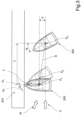
Figure 2 shows the marine vessel being maneuvered according to a first control strategy. In this first example avessel 200 is placed alongside adock 201, with the side of the vessel arranged parallel to the side of the dock. The operator will then operate the vessel propulsion system, which comprises two or more drive units, requesting a transverse thrust sufficient to hold thevessel 200 against thedock 201, where after the operator issues an operating command to a control unit (seeFig.1 ) indicating that a sideways bollard push function is requested. The operating command is registered in response to an input signal from a joystick, a graphical user interface (GUI) or to input signals from at least one throttle controller and a helm controller, optionally in combination with a switch. When the sideways bollard push function is activated, the drive units will maintain the requested transverse thrust in the direction of the arrow F to maintain the side of the vessel in contact with the dock in a desired vessel position P1. - The control unit will then continuously monitor if a deviation has occurred between the current vessel position P2 and the desired vessel position P1. During the manoeuvre, a displacement in the transverse and/or the longitudinal direction of the vessel is constantly monitored. If the ambient conditions are unfavourable, the vessel can be suddenly displaced away from or along the dock, by a gust of wind, indicated by an arrow W, and/or a sudden water current, indicated by an arrow C. If a deviation of the current vessel position P2 relative to the desired vessel position P1 has exceeded a predetermined distance, then the requested sideways bollard push function is deactivated. The predetermined distance can be measured as a transverse distance X at right angles to the dock, a longitudinal distance Y parallel to the dock, or as a distance D between the desired vessel position P1 and the current vessel position P2. When the selected distance has exceeded the predetermined distance, the sideways bollard push function is deactivated and the thrust from the drive units is inhibited. Suitable values for the predetermined distances X, Y, D described above can be one or more pre-set values selected by the manufacturer or can be selected by the operator. The distance can be selected up to, for instance, 1 m.
- The thrust from the drive units is inhibited in order to avoid further unexpected displacement of the vessel caused by the requested thrust and to give the operator time to resume control over the vessel. Optionally, the control unit can automatically activate a position hold function in response to a deactivation of the sideways bollard push function. In this way, the vessel can be prevented from drifting further away from the vessel position P2 where the deactivation of the sideways bollard push function occurred. This will provide additional time to resume control over the vessel, should the operator not be in the immediate vicinity of the controllers at the operating position (see
Fig.1 ). -
Figure 3 shows the marine vessel being maneuvered according to a second control strategy. In this second example avessel 200 is placed at an angle relative to adock 201, with the bow of the vessel arranged against the dock. Here, the longitudinal direction, or heading of the vessel is arranged at right angles to the side of the dock. The operator then operates the vessel propulsion system, which comprises two or more drive units, requesting a forward thrust sufficient to hold thevessel 200 against thedock 201, where after the operator issues an operating command to a control unit (seeFig.1 ) indicating that a bow bollard push function is requested. The operating command is registered in response to an input signal from a joystick, a graphical user interface (GUI) or to input signals from at least one throttle controller and a helm controller, optionally in combination with a switch. When the bow bollard push function is actuated, the drive units will maintain the requested forward thrust in the direction of the arrow F to maintain the bow of the vessel in contact with the dock in a desired vessel position P1. - The control unit will then continuously monitor if a deviation has occurred between a current heading H2 at a current vessel positions P2' and the desired heading H1 at the desired vessel position P1. During the manoeuvre, at least an angular displacement of the vessel, where the bow is at least initially a pivot point, is constantly monitored. If the ambient conditions are unfavourable, the vessel can be suddenly displaced away from or along the dock, by a gust of wind, indicated by an arrow W, and/or a sudden water current, indicated by an arrow C. If the current vessel heading H2 is suddenly displaced a predetermined angle α away from the initial desired vessel heading H1 relative to the dock, then the requested bow bollard push function is deactivated. The predetermined angle α is measured as an angular displacement representing a change in the vessel heading to either side of the desired vessel heading H1. In
Figure 3 , this would entail that the vessel would remain with the bow in the initial, desired position while the current heading H2 changes relative to the desired heading H1. - Optionally, a displacement in the transverse and/or the longitudinal direction of the vessel is simultaneously monitored (see
Fig.2 ). If a deviation of the current vessel position P2' P2" relative to the desired vessel position P1 has exceeded a predetermined distance before the angle is exceeded, then the requested bow bollard push function is deactivated. The predetermined distance can be measured as a transverse distance X at right angles to the dock, a longitudinal distance Y parallel to the dock, or as a distance D between the desired vessel position P1 and the current vessel position P2". By monitoring both parameters, any undesired displacement whether angular or linear can be detected. When either one of the predetermined angle α or the predetermined distance X, Y, D has exceeded its predetermined value, the bollard push function is deactivated and the requested thrust from the drive units is inhibited.Figure 3 shows the latter example, where simultaneous angular and linear displacement has occurred to move the vessel to a new heading H2" and a new position P2". Suitable values for the predetermined angle α can be one or more pre-set values selected by the manufacturer or can be selected by the operator. The angle can be set at angles up to 20°. - The thrust from the drive units is inhibited in order to avoid further unexpected displacement of the vessel caused by the requested thrust and to give the operator time to resume control over the vessel. Optionally, the control unit can automatically activate a position hold function in response to a deactivation of the bow bollard push function. In this way, the vessel can be prevented from drifting further away from the vessel position P2', P2'" where the deactivation of the bow bollard push function occurred. This will provide additional time to resume control over the vessel, should the operator not be in the immediate vicinity of the controllers at the operating position (see
Fig.1 ). - According to a further example, the method involves monitoring if the rate of change of the deviation for a current vessel position relative to the desired vessel position has exceeded a predetermined value. For instance, if the vessel in
Figure 2 or3 is placed with its side or bow, respectively, against a dock when the bollard push manoeuvre is being performed, then the drive units will provide a suitable thrust to maintain the side or the bow of the vessel in contact with the dock. During the manoeuvre, any angular or linear displacement of the vessel is constantly monitored. If the vessel is displaced linearly or angularly away from the initial vessel position against the dock at a rate that exceeds a predetermined rate of change, then the requested bollard push function is deactivated. -
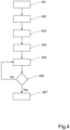
Figure 4 shows a flow chart illustrating a first alternative method for controlling the vessel. The method involves performing afirst step 401 where an operating command indicating a requested bollard push function is registered. In a second step 402 a current vessel position is detect using a suitable GNSS means, such as a Differential Global Positioning System (DGPS). In athird step 403 the current vessel position is registering as a desired vessel position in a control unit. In afourth step 404 the control unit executes the requested bollard push function, using currently requested throttle and helm settings to hold the vessel in a desired position. In afifth step 405 the control unit monitors the current vessel position in order to detect a deviation relative to the desired vessel position. - In a
sixth step 406 the control unit compares a detected deviation parameter to a predetermined deviation value. The detected deviation can be that the vessel has been displaced a predetermined distance from the desired vessel position to the current vessel position. Alternatively, or in combination, the detected deviation can be that the vessel heading has been displaced a predetermined angle from the desired vessel heading to the current vessel heading. Further, the detected deviation can be that the rate of change of the linear or angular deviation for a current vessel position relative to the desired vessel position has exceeded a predetermined value. If a deviation is not detected, then the process returns to thefifth step 405, where the control unit continues to monitor any deviation from the current vessel position. If a detected deviation relative to the desired vessel position has exceeded a predetermined value, then the process proceeds to aseventh step 407, where the requested bollard push function is deactivated. In this example, deactivation of the bollard push function will also involve an inhibition of the thrust from the drive units. The operator will then take over and control the vessel manually. -
Figure 5 shows a flow chart illustrating a second alternative method for controlling the vessel. In the same way as described for the first alternative method, the second alternative method involves performing afirst step 501 where an operating command indicating a requested bollard push function is registered. In a second step 502 a current vessel position is detect using a suitable GNSS means, such as a Differential Global Positioning System (DGPS). In athird step 503 the current vessel position is registered as a desired vessel position in a control unit. In afourth step 504 the control unit executes the requested bollard push function, using currently requested throttle and helm settings to hold the vessel in a desired position. In afifth step 505 the control unit monitors the current vessel position in order to detect a deviation relative to the desired vessel position. - In a
sixth step 506 the control unit compares a detected deviation parameter to a predetermined deviation value. The detected deviation can be that the vessel has been displaced a predetermined distance from the desired vessel position to the current vessel position. Alternatively, or in combination, the detected deviation can be that the vessel heading has been displaced a predetermined angle from the desired vessel heading to the current vessel heading. Further, the detected deviation can be that the rate of change of the linear or angular deviation for a current vessel position relative to the desired vessel position has exceeded a predetermined value. If a deviation is not detected, then the process returns to thefifth step 505, where the control unit continues to monitor any deviation from the current vessel position. If a detected deviation relative to the desired vessel position has exceeded a predetermined value, then the process proceeds to aseventh step 507, where the requested bollard push function is deactivated. Deactivation of the bollard push function also involves a temporary inhibition of the thrust from the drive units. - Following the deactivation of the bollard push function the process proceeds to an eight
step 508 where an updated current vessel position is registered in the control unit, Subsequently, the control unit will execute a position hold function in aninth step 509. The position hold function is performed in order to maintain the vessel in the updated current vessel position. The updated current vessel position can be the position of the vessel at the time when the requested bollard push function is deactivated and/or the thrust from the drive units is inhibited. This operation will prevent the vessel from drifting further away from the dock or towards the dock under the influence of external factors, such as wind or water currents. The vessel position is preferably determined by a Global Navigation Satellite System (GNSS) with a suitable accuracy, such as a Differential Global Positioning System (DGPS). The operator can then take over and control the vessel manually when desired. - The methods described in connection with
Figures 4 and5 are applicable to both sideways and bow bollard push manoeuvres. - According to a second aspect the disclosure relates to a
control unit Figures 1 &6 and comprises processing circuitry which is configured to receive an input indicating a requested vessel function. In particular, the processing circuitry is configured to: - register an operating command indicating a requested bollard push function;
- detect a current vessel position;
- register the current vessel position as a desired vessel position;
- execute the requested bollard push function;
- monitor the current vessel position in order to detect a deviation relative to the desired vessel position;
- deactivate the requested bollard push function.
- Optionally, the processing circuitry is further configured to:
- register an updated current vessel position; and
- execute a station keeping function in order to maintain the vessel in the updated current vessel position.
- The present disclosure also relates to a computer program, and a computer program product to be used with a computer for executing the method as described in any one of the above examples.
Figure 6 shows the method described in connection withFigures 4 or5 applied on a computer arrangement. -
Figure 6 shows anapparatus 600 according to the present disclosure, comprising anon-volatile memory 620, aprocessor 610 and a read-write memory 660. Thememory 620 has afirst memory part 630, in which a computer program for controlling theapparatus 600 is stored. The computer program in thememory part 630 for controlling theapparatus 600 can be an operating system. Theapparatus 600 can be enclosed in, for example, a control unit, such as thecontrol unit 111 inFigure 1 . The data-processing unit 610 can comprise, for example, a microcomputer. Thememory 620 also has asecond memory part 640, in which a program for controlling the docking manoeuvre according to the invention is stored. In an alternative embodiment, the program for controlling the docking manoeuvre is stored in a separatenon-volatile storage medium 650 for data, such as, for example, a CD or an exchangeable semiconductor memory. The program can be stored in an executable form or in a compressed state. - When it is stated below that the data-
processing unit 610 runs a specific function, it should be clear that the data-processing unit 610 is running a specific part of the program stored in thememory 640 or a specific part of the program stored in thenon-volatile storage medium 650. The data-processing unit 610 is tailored for communication with thestorage memory 650 through adata bus 614. The data-processing unit 610 is also tailored for communication with thememory 620 through adata bus 612. In addition, the data-processing unit 610 is tailored for communication with thememory 660 through adata bus 611. The data-processing unit 610 is also tailored for communication with adata port 690 by the use of adata bus 615. - The method according to the present disclosure can be executed by the data-
processing unit 610, by the data-processing unit 610 running the program stored in thememory 640 or the program stored in thenon-volatile storage medium 650. - The present disclosure should not be deemed to be limited to the embodiments described above, but rather a number of further variants and modifications are conceivable within the scope of the following patent claims.
Claims (14)
- A method to control a marine vessel (100) comprising two or more drive units (102, 103); the method involving the steps of:- registering an operating command indicating a requested bollard push function;- detecting a current vessel position;- registering the current vessel position as a desired vessel position (P1);- executing the requested bollard push function by controlling thrust and direction of the drive units in order to push the vessel against a fixed structure at a requested heading with a predetermined force;- monitoring the current vessel position (P2; P2") in order to detect a deviation relative to the desired vessel position (P1);characterized by: if a detected deviation relative to the desired vessel position has exceeded a predetermined value;- deactivating the requested bollard push function, wherein deactivation of the bollard push function will at least involve an inhibition of the thrust from the drive units.
- The method according to claim 1, involving monitoring if the deviation of a current vessel position relative to the desired vessel position has exceeded a predetermined distance.
- The method according to claim 1 or 2, involving monitoring if the deviation of a current vessel heading relative to the desired vessel heading has exceeded a predetermined angle.
- The method according to any one of claims 1-3, involving monitoring if the rate of change of the deviation for a current vessel position relative to the desired vessel position has exceeded a predetermined value.
- The method according to any one of claims 1-4, involving registering the bollard push function in response to an input signal from a joystick.
- The method according to any one of claims 1-4, involving registering the bollard push function in response to an input signal from a graphical user interface.
- The method according to any one of claims 1-4, involving registering the bollard push function in response to input signals from at least one throttle controller and a helm controller.
- The method according to any one of claims 1-7, involving disengaging the drive units when deactivating the requested bollard push function.
- The method according to any one of claims 1-7, involving the further steps of:- registering an updated current vessel position; and- executing a position hold function in order to maintain the updated current vessel position.
- The method according to any one of the above claims 1-9, wherein the vessel position is determined by a Global Navigation Satellite System.
- A control unit (111; 600) arranged to control a marine vessel (100) comprising two or more propulsion units (102, 103), the control unit (111; 600) comprising processing circuitry, the processing circuitry being configured to receive an input indicating a requested vessel function, wherein the processing circuitry is configured to:- register an operating command indicating a requested bollard push function;- detect a current vessel position;- register the current vessel position as a desired vessel position (P1);- execute the requested bollard push function by controlling thrust and direction of the drive units in order to push the vessel against a fixed structure at a requested heading with a predetermined force;- monitor the current vessel position (P2; P2") in order to detect a deviation relative to the desired vessel position (P1);characterized in that if a detected deviation relative to the desired vessel position has exceeded a predetermined value, the processing circuitry is configured to:- deactivate the requested bollard push function, wherein deactivation of the bollard push function will at least involve an inhibition of the thrust from the drive units;- register an updated current vessel position; and- execute a station keeping function in order to maintain the updated current vessel position.
- Marine vessel, wherein the marine vessel (100) comprises a control unit (111, 600) according to claim 11.
- A computer program comprising program code means for performing the method according to claim 1 when said program is run on a computer.
- A computer program product comprising program code means stored on a computer readable medium for performing the method according to claim 1 when said program product is run on a computer.
Applications Claiming Priority (1)
| Application Number | Priority Date | Filing Date | Title |
|---|---|---|---|
| PCT/EP2020/064034 WO2021233533A1 (en) | 2020-05-20 | 2020-05-20 | Control method and control unit for a marine vessel |
Publications (3)
| Publication Number | Publication Date |
|---|---|
| EP4154079A1 EP4154079A1 (en) | 2023-03-29 |
| EP4154079B1 true EP4154079B1 (en) | 2024-07-03 |
| EP4154079C0 EP4154079C0 (en) | 2024-07-03 |
Family
ID=70847357
Family Applications (1)
| Application Number | Title | Priority Date | Filing Date |
|---|---|---|---|
| EP20727969.6A Active EP4154079B1 (en) | 2020-05-20 | 2020-05-20 | Control method and control unit for a marine vessel |
Country Status (4)
| Country | Link |
|---|---|
| US (1) | US12436532B2 (en) |
| EP (1) | EP4154079B1 (en) |
| CN (1) | CN115668086B (en) |
| WO (1) | WO2021233533A1 (en) |
Families Citing this family (2)
| Publication number | Priority date | Publication date | Assignee | Title |
|---|---|---|---|---|
| AU2021100933A4 (en) * | 2020-12-17 | 2021-04-29 | C W F Hamilton & Co Limited | Marine vessel fender and control system |
| WO2025179430A1 (en) * | 2024-02-26 | 2025-09-04 | 广东逸动科技有限公司 | Method for realizing position keeping of waterborne vehicle on basis of single thruster, and related device |
Family Cites Families (14)
| Publication number | Priority date | Publication date | Assignee | Title |
|---|---|---|---|---|
| US6273771B1 (en) * | 2000-03-17 | 2001-08-14 | Brunswick Corporation | Control system for a marine vessel |
| US6299496B1 (en) * | 2000-06-19 | 2001-10-09 | Brunswick Corporation | Exhaust control system for a marine vessel |
| US6511354B1 (en) * | 2001-06-04 | 2003-01-28 | Brunswick Corporation | Multipurpose control mechanism for a marine vessel |
| WO2006062416A1 (en) * | 2004-12-07 | 2006-06-15 | Cwf Hamilton & Co Limited | Propulsion and control system for a marine vessel |
| US9274528B2 (en) * | 2005-06-23 | 2016-03-01 | Marine 1, Llc | Marine vessel control system |
| US7305928B2 (en) * | 2005-10-12 | 2007-12-11 | Brunswick Corporation | Method for positioning a marine vessel |
| US8145371B2 (en) * | 2006-06-02 | 2012-03-27 | Cwf Hamilton & Co. Limited | Dynamic control system for a marine vessel |
| WO2010039952A1 (en) * | 2008-10-02 | 2010-04-08 | Zf Friedrichshafen Ag | Joystick controlled marine maneuvering system |
| EP3051376B1 (en) | 2015-01-27 | 2017-12-20 | ABB Schweiz AG | Ship emergency stopping |
| US10259555B2 (en) * | 2016-08-25 | 2019-04-16 | Brunswick Corporation | Methods for controlling movement of a marine vessel near an object |
| US10167057B1 (en) * | 2017-08-22 | 2019-01-01 | Yamaha Hatsudoki Kabushiki Kaisha | Jet boat |
| JP6969047B2 (en) * | 2018-03-20 | 2021-11-24 | 三井E&S造船株式会社 | Automatic ship maneuvering system |
| SG11202011726WA (en) | 2018-06-01 | 2020-12-30 | Waertsilae Sam Electronics Gmbh | Method, device and apparatus for autonomous docking of marine vessel |
| CN209854667U (en) | 2019-02-18 | 2019-12-27 | 浙江国际海运职业技术学院 | Dynamic buffering and anti-collision device for ship berthing |
-
2020
- 2020-05-20 US US17/999,282 patent/US12436532B2/en active Active
- 2020-05-20 CN CN202080100890.7A patent/CN115668086B/en active Active
- 2020-05-20 EP EP20727969.6A patent/EP4154079B1/en active Active
- 2020-05-20 WO PCT/EP2020/064034 patent/WO2021233533A1/en not_active Ceased
Also Published As
| Publication number | Publication date |
|---|---|
| US12436532B2 (en) | 2025-10-07 |
| WO2021233533A1 (en) | 2021-11-25 |
| US20230205207A1 (en) | 2023-06-29 |
| CN115668086B (en) | 2024-03-05 |
| EP4154079C0 (en) | 2024-07-03 |
| CN115668086A (en) | 2023-01-31 |
| EP4154079A1 (en) | 2023-03-29 |
Similar Documents
| Publication | Publication Date | Title |
|---|---|---|
| US11554843B2 (en) | Course control system for marine vessel, and marine vessel | |
| US10457371B2 (en) | Vessel steering apparatus | |
| US12066827B2 (en) | Watercraft auto-docking system and watercraft auto-docking method | |
| EP3406516B1 (en) | Ship maneuvering device and ship provided therewith | |
| EP3819203B1 (en) | Method for controlling posture of a marine vessel, control system for controlling posture of a marine vessel, and a marine vessel | |
| AU2009298414A1 (en) | Joystick controlled marine maneuvering system | |
| EP4480809A1 (en) | Uniaxial twin-rudder ship having automatic docking function | |
| EP4389589B1 (en) | Steering system having function of correcting steering angle of uniaxial two-rudder vessel | |
| US11932370B1 (en) | Systems and methods for steering marine propulsion devices | |
| US12436532B2 (en) | Control method and control unit for a marine vessel | |
| EP3434580B1 (en) | Ship | |
| EP4154080B1 (en) | Method to control a marine vessel, a control unit and a vessel | |
| JP2023159902A (en) | Hull motion control device for uniaxial, two rudder vessel | |
| KR20250012117A (en) | Shipbuilding system and shipbuilding method | |
| US20260064134A1 (en) | Automatic watercraft maneuvering system and watercraft control method | |
| EP4632521B1 (en) | Autopilot control of a marine vessel | |
| US20260062109A1 (en) | Automatic watercraft maneuvering system and watercraft control method | |
| JP2025167102A (en) | Automatic ship steering system and method |
Legal Events
| Date | Code | Title | Description |
|---|---|---|---|
| STAA | Information on the status of an ep patent application or granted ep patent |
Free format text: STATUS: UNKNOWN |
|
| STAA | Information on the status of an ep patent application or granted ep patent |
Free format text: STATUS: THE INTERNATIONAL PUBLICATION HAS BEEN MADE |
|
| PUAI | Public reference made under article 153(3) epc to a published international application that has entered the european phase |
Free format text: ORIGINAL CODE: 0009012 |
|
| STAA | Information on the status of an ep patent application or granted ep patent |
Free format text: STATUS: REQUEST FOR EXAMINATION WAS MADE |
|
| 17P | Request for examination filed |
Effective date: 20221124 |
|
| AK | Designated contracting states |
Kind code of ref document: A1 Designated state(s): AL AT BE BG CH CY CZ DE DK EE ES FI FR GB GR HR HU IE IS IT LI LT LU LV MC MK MT NL NO PL PT RO RS SE SI SK SM TR |
|
| DAV | Request for validation of the european patent (deleted) | ||
| DAX | Request for extension of the european patent (deleted) | ||
| GRAP | Despatch of communication of intention to grant a patent |
Free format text: ORIGINAL CODE: EPIDOSNIGR1 |
|
| STAA | Information on the status of an ep patent application or granted ep patent |
Free format text: STATUS: GRANT OF PATENT IS INTENDED |
|
| INTG | Intention to grant announced |
Effective date: 20240116 |
|
| GRAS | Grant fee paid |
Free format text: ORIGINAL CODE: EPIDOSNIGR3 |
|
| GRAA | (expected) grant |
Free format text: ORIGINAL CODE: 0009210 |
|
| STAA | Information on the status of an ep patent application or granted ep patent |
Free format text: STATUS: THE PATENT HAS BEEN GRANTED |
|
| AK | Designated contracting states |
Kind code of ref document: B1 Designated state(s): AL AT BE BG CH CY CZ DE DK EE ES FI FR GB GR HR HU IE IS IT LI LT LU LV MC MK MT NL NO PL PT RO RS SE SI SK SM TR |
|
| REG | Reference to a national code |
Ref country code: CH Ref legal event code: EP |
|
| REG | Reference to a national code |
Ref country code: DE Ref legal event code: R096 Ref document number: 602020033323 Country of ref document: DE |
|
| U01 | Request for unitary effect filed |
Effective date: 20240716 |
|
| U07 | Unitary effect registered |
Designated state(s): AT BE BG DE DK EE FI FR IT LT LU LV MT NL PT SE SI Effective date: 20240729 |
|
| PG25 | Lapsed in a contracting state [announced via postgrant information from national office to epo] |
Ref country code: NO Free format text: LAPSE BECAUSE OF FAILURE TO SUBMIT A TRANSLATION OF THE DESCRIPTION OR TO PAY THE FEE WITHIN THE PRESCRIBED TIME-LIMIT Effective date: 20241003 |
|
| PG25 | Lapsed in a contracting state [announced via postgrant information from national office to epo] |
Ref country code: GR Free format text: LAPSE BECAUSE OF FAILURE TO SUBMIT A TRANSLATION OF THE DESCRIPTION OR TO PAY THE FEE WITHIN THE PRESCRIBED TIME-LIMIT Effective date: 20241004 Ref country code: PL Free format text: LAPSE BECAUSE OF FAILURE TO SUBMIT A TRANSLATION OF THE DESCRIPTION OR TO PAY THE FEE WITHIN THE PRESCRIBED TIME-LIMIT Effective date: 20240703 |
|
| PG25 | Lapsed in a contracting state [announced via postgrant information from national office to epo] |
Ref country code: IS Free format text: LAPSE BECAUSE OF FAILURE TO SUBMIT A TRANSLATION OF THE DESCRIPTION OR TO PAY THE FEE WITHIN THE PRESCRIBED TIME-LIMIT Effective date: 20241103 |
|
| PG25 | Lapsed in a contracting state [announced via postgrant information from national office to epo] |
Ref country code: HR Free format text: LAPSE BECAUSE OF FAILURE TO SUBMIT A TRANSLATION OF THE DESCRIPTION OR TO PAY THE FEE WITHIN THE PRESCRIBED TIME-LIMIT Effective date: 20240703 Ref country code: CZ Free format text: LAPSE BECAUSE OF FAILURE TO SUBMIT A TRANSLATION OF THE DESCRIPTION OR TO PAY THE FEE WITHIN THE PRESCRIBED TIME-LIMIT Effective date: 20240703 |
|
| PG25 | Lapsed in a contracting state [announced via postgrant information from national office to epo] |
Ref country code: RS Free format text: LAPSE BECAUSE OF FAILURE TO SUBMIT A TRANSLATION OF THE DESCRIPTION OR TO PAY THE FEE WITHIN THE PRESCRIBED TIME-LIMIT Effective date: 20241003 Ref country code: ES Free format text: LAPSE BECAUSE OF FAILURE TO SUBMIT A TRANSLATION OF THE DESCRIPTION OR TO PAY THE FEE WITHIN THE PRESCRIBED TIME-LIMIT Effective date: 20240703 |
|
| PG25 | Lapsed in a contracting state [announced via postgrant information from national office to epo] |
Ref country code: RS Free format text: LAPSE BECAUSE OF FAILURE TO SUBMIT A TRANSLATION OF THE DESCRIPTION OR TO PAY THE FEE WITHIN THE PRESCRIBED TIME-LIMIT Effective date: 20241003 Ref country code: PL Free format text: LAPSE BECAUSE OF FAILURE TO SUBMIT A TRANSLATION OF THE DESCRIPTION OR TO PAY THE FEE WITHIN THE PRESCRIBED TIME-LIMIT Effective date: 20240703 Ref country code: NO Free format text: LAPSE BECAUSE OF FAILURE TO SUBMIT A TRANSLATION OF THE DESCRIPTION OR TO PAY THE FEE WITHIN THE PRESCRIBED TIME-LIMIT Effective date: 20241003 Ref country code: IS Free format text: LAPSE BECAUSE OF FAILURE TO SUBMIT A TRANSLATION OF THE DESCRIPTION OR TO PAY THE FEE WITHIN THE PRESCRIBED TIME-LIMIT Effective date: 20241103 Ref country code: HR Free format text: LAPSE BECAUSE OF FAILURE TO SUBMIT A TRANSLATION OF THE DESCRIPTION OR TO PAY THE FEE WITHIN THE PRESCRIBED TIME-LIMIT Effective date: 20240703 Ref country code: GR Free format text: LAPSE BECAUSE OF FAILURE TO SUBMIT A TRANSLATION OF THE DESCRIPTION OR TO PAY THE FEE WITHIN THE PRESCRIBED TIME-LIMIT Effective date: 20241004 Ref country code: ES Free format text: LAPSE BECAUSE OF FAILURE TO SUBMIT A TRANSLATION OF THE DESCRIPTION OR TO PAY THE FEE WITHIN THE PRESCRIBED TIME-LIMIT Effective date: 20240703 Ref country code: CZ Free format text: LAPSE BECAUSE OF FAILURE TO SUBMIT A TRANSLATION OF THE DESCRIPTION OR TO PAY THE FEE WITHIN THE PRESCRIBED TIME-LIMIT Effective date: 20240703 |
|
| PG25 | Lapsed in a contracting state [announced via postgrant information from national office to epo] |
Ref country code: SM Free format text: LAPSE BECAUSE OF FAILURE TO SUBMIT A TRANSLATION OF THE DESCRIPTION OR TO PAY THE FEE WITHIN THE PRESCRIBED TIME-LIMIT Effective date: 20240703 |
|
| PG25 | Lapsed in a contracting state [announced via postgrant information from national office to epo] |
Ref country code: SK Free format text: LAPSE BECAUSE OF FAILURE TO SUBMIT A TRANSLATION OF THE DESCRIPTION OR TO PAY THE FEE WITHIN THE PRESCRIBED TIME-LIMIT Effective date: 20240703 |
|
| PLBE | No opposition filed within time limit |
Free format text: ORIGINAL CODE: 0009261 |
|
| STAA | Information on the status of an ep patent application or granted ep patent |
Free format text: STATUS: NO OPPOSITION FILED WITHIN TIME LIMIT |
|
| 26N | No opposition filed |
Effective date: 20250404 |
|
| U20 | Renewal fee for the european patent with unitary effect paid |
Year of fee payment: 6 Effective date: 20250526 |
|
| PGFP | Annual fee paid to national office [announced via postgrant information from national office to epo] |
Ref country code: GB Payment date: 20250520 Year of fee payment: 6 |
|
| REG | Reference to a national code |
Ref country code: CH Ref legal event code: H13 Free format text: ST27 STATUS EVENT CODE: U-0-0-H10-H13 (AS PROVIDED BY THE NATIONAL OFFICE) Effective date: 20251223 |
|
| PG25 | Lapsed in a contracting state [announced via postgrant information from national office to epo] |
Ref country code: CH Free format text: LAPSE BECAUSE OF NON-PAYMENT OF DUE FEES Effective date: 20250531 |
|
| PG25 | Lapsed in a contracting state [announced via postgrant information from national office to epo] |
Ref country code: MC Free format text: LAPSE BECAUSE OF FAILURE TO SUBMIT A TRANSLATION OF THE DESCRIPTION OR TO PAY THE FEE WITHIN THE PRESCRIBED TIME-LIMIT Effective date: 20240703 |
|
| PG25 | Lapsed in a contracting state [announced via postgrant information from national office to epo] |
Ref country code: IE Free format text: LAPSE BECAUSE OF NON-PAYMENT OF DUE FEES Effective date: 20250520 |
|
| PG25 | Lapsed in a contracting state [announced via postgrant information from national office to epo] |
Ref country code: RO Free format text: LAPSE BECAUSE OF FAILURE TO SUBMIT A TRANSLATION OF THE DESCRIPTION OR TO PAY THE FEE WITHIN THE PRESCRIBED TIME-LIMIT Effective date: 20240703 |