EP4153958B1 - Hydraulische drehmomentmessvorrichtung für eine flugzeugmotoreinheit - Google Patents
Hydraulische drehmomentmessvorrichtung für eine flugzeugmotoreinheit Download PDFInfo
- Publication number
- EP4153958B1 EP4153958B1 EP21732443.3A EP21732443A EP4153958B1 EP 4153958 B1 EP4153958 B1 EP 4153958B1 EP 21732443 A EP21732443 A EP 21732443A EP 4153958 B1 EP4153958 B1 EP 4153958B1
- Authority
- EP
- European Patent Office
- Prior art keywords
- hydraulic
- pressure
- gearbox
- wall
- deformable
- Prior art date
- Legal status (The legal status is an assumption and is not a legal conclusion. Google has not performed a legal analysis and makes no representation as to the accuracy of the status listed.)
- Active
Links
Images



Classifications
-
- G—PHYSICS
- G01—MEASURING; TESTING
- G01L—MEASURING FORCE, STRESS, TORQUE, WORK, MECHANICAL POWER, MECHANICAL EFFICIENCY, OR FLUID PRESSURE
- G01L3/00—Measuring torque, work, mechanical power, or mechanical efficiency, in general
- G01L3/02—Rotary-transmission dynamometers
- G01L3/14—Rotary-transmission dynamometers wherein the torque-transmitting element is other than a torsionally-flexible shaft
- G01L3/1407—Rotary-transmission dynamometers wherein the torque-transmitting element is other than a torsionally-flexible shaft involving springs
- G01L3/1414—Rotary-transmission dynamometers wherein the torque-transmitting element is other than a torsionally-flexible shaft involving springs using mechanical or hydraulic transducers
-
- G—PHYSICS
- G01—MEASURING; TESTING
- G01L—MEASURING FORCE, STRESS, TORQUE, WORK, MECHANICAL POWER, MECHANICAL EFFICIENCY, OR FLUID PRESSURE
- G01L5/00—Apparatus for, or methods of, measuring force, work, mechanical power, or torque, specially adapted for specific purposes
- G01L5/12—Apparatus for, or methods of, measuring force, work, mechanical power, or torque, specially adapted for specific purposes for measuring axial thrust in a rotary shaft, e.g. of propulsion plants
-
- G—PHYSICS
- G01—MEASURING; TESTING
- G01M—TESTING STATIC OR DYNAMIC BALANCE OF MACHINES OR STRUCTURES; TESTING OF STRUCTURES OR APPARATUS, NOT OTHERWISE PROVIDED FOR
- G01M15/00—Testing of engines
- G01M15/02—Details or accessories of testing apparatus
-
- G—PHYSICS
- G01—MEASURING; TESTING
- G01L—MEASURING FORCE, STRESS, TORQUE, WORK, MECHANICAL POWER, MECHANICAL EFFICIENCY, OR FLUID PRESSURE
- G01L1/00—Measuring force or stress, in general
- G01L1/02—Measuring force or stress, in general by hydraulic or pneumatic means
Definitions
- the present invention relates to a hydraulic torque meter, in particular for an aircraft engine.
- the technical background includes in particular the documents US 3587304 A1 And US 5337612 A1 .
- hydraulic torque meters In the aeronautical field, hydraulic torque meters are known that rely on an automatic hydraulic pressure regulation mechanism in the torque measurement.
- the hydraulic pressure regulated by the aforementioned mechanism is a simple function of the torque delivered by the relevant engine. Indeed, the axial thrust on one or more intermediate pinions, for example with helical teeth, of a reducer is proportional to the torque passing through this same reducer.
- a sensor measures this regulated hydraulic pressure and, by taking into account a few conformation coefficients determined during the engine acceptance test, a computer deduces from this pressure measurement the torque actually delivered by the engine.
- Such a known hydraulic torque meter 320 implemented in a transmission box 300 of a power unit (not illustrated) for a helicopter, is described with reference to figures 1 , 2A , 2B And 3 .
- the cover 3210 of a hydraulic piston 321, described below, and a pump-filter support block carrying a pressure sensor 328, also described below, are visible on the transmission box 300 in figure 1 .
- a cross section of the transmission box 300 is illustrated in detail in Fig. 2B .
- the transmission box 300 here has a casing 304 and a pinion 306, mounted to rotate in the casing 304.
- a shaft 306a of the pinion 306 is connected in a pivot connection with the hydraulic piston 321 of the torque meter 320 to the by means of a bearing 308.
- the axial thrust exerted by the pinion 306 on the piston 321 has the effect of regulating the opening of a valve 322, that is to say of modulating the importance of an oil leak from a supply circuit 323 supplied from a pump 324 ( Figures 2A And 2B ).
- a balance is thus achieved between the axial thrust exerted by the pinion 306 and the thrust of the hydraulic fluid on the piston 321.
- the pressure thus regulated in the supply circuit 323 is measured by the pressure sensor 328 ( figures 1 , 2A , 3 ).
- the sensor 328 here has a hydraulic piston 3280 and a resistive element 3281.
- the pressure F exerted by the fluid on the hydraulic piston 3280 is transformed in 3281 into an output signal, here an electrical voltage proportional to the pressure of the fluid.
- An electrical connector 3282 ( figure 3 ) allows the output signal to be transmitted to a computing unit 329, which controls a visual indicator 330 in the aircraft cabin.
- a rod 30 is movable in translation in a longitudinal direction under the effect of an axial thrust 31 representative of the torque to be measured.
- a hydraulic circuit 40 in which a fluid 38 circulates is provided.
- This torque meter also comprises a pressure capsule 46 comprising a pressure chamber 36 supplied with fluid by the hydraulic circuit 40.
- a flexible and sealed membrane 32 is in contact with the fluid of the pressure chamber 36, extends in a plane substantially perpendicular to said rod 30 and is securely connected to one end of the rod 30 so that a longitudinal movement of the rod 30 causes a deformation of the membrane 32.
- This device also comprises a leakage orifice 44 for the fluid 38 from the pressure chamber 36, and a valve 48 configured to regulate the pressure of the fluid 38 in said pressure chamber 36 as a function of the deformation of said membrane 32.
- the hydraulic pressure regulation is also ensured by a continuous and excess supply of the hydraulic chamber, taken from the engine lubrication oil circuit.
- a valve limits the flow leaving the hydraulic chamber, which automatically adjusts the pressure until it exactly compensates for the axial thrust of the intermediate gear.
- this control device can take on the different engines concerned are quite diverse and can be improved. Their fundamental characteristics (in particular the valve opening-flow rate - differential pressure relationship) are not known experimentally, and their sensitivity to manufacturing tolerances must be determined on a case-by-case basis.
- the torques in rapid transient conditions of the engine are not precisely measured because these systems rely on the establishment of a state of equilibrium dependent on the performance of the engine oil circuit.
- the measurement of the maximum torque reached during a transient condition is uncertain, which can lead to exceeding the torque admissible by the engine without this being detected by the engine control and monitoring system.
- This type of system also represents an energy loss taken from the lubrication circuit.
- the present invention aims to solve the drawbacks of known solutions and proposes a simple, effective and economical solution to this problem.
- the present invention aims in particular to simplify existing solutions and improve the reliability and efficiency of torque measurements.
- the enclosure is hermetically sealed.
- the invention also relates to a transmission box for an aircraft engine unit, comprising a hydraulic torque measuring device mentioned above, the transmission box comprising at least one pinion having a shaft extending along a longitudinal axis, the deformable wall being connected in a pivot connection to the shaft.
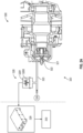
- gearbox 3 for example a main gearbox of a power unit (not shown) of a helicopter.
- the gearbox is however not limited to this type of power unit and can be applied to other types of power units, as well as to other types of aircraft, in particular when a torque is to be measured.
- the transmission box 3 comprises a rigid casing 4 and a set of pinions 5.
- the set of pinions 5 comprises, for example, at least a first pinion 6 and a second pinion 7, meshing with each other at teeth 6a, respectively 7a.
- the pinion set 5 belongs to a reducer of the transmission box 3 which is not illustrated in detail.
- the pinion 6 is for example, but not limited to, an intermediate pinion of this reducer.
- the pinion 6 generally extends around a longitudinal axis A and is rotatable around it.
- the teeth 6a of the pinion 6 are distributed regularly around the longitudinal axis A.
- the pinion 6 comprises a shaft 6b around which it is configured to rotate.
- the shaft 6b is here a hollow shaft and has a succession of hollow cylindrical portions 6b1, 6b2, 6b3, of respective diameter decreasing towards a hydraulic torque meter 20 described below.
- a web 6c extends here from the end of the cylindrical portion 6b1 adjacent to the cylindrical portion 6b2.
- the web 6c carries a cylindrical crown 6d provided with teeth 6a.
- a distal end 6e extends to the end of the cylindrical portion 6b3.
- the casing 4 comprises a plurality of walls, of which here only two walls 10 and 11 are shown.
- the wall 11 delimits an interior volume 12 in which the end 6e and the cylindrical portions 6b2 and 6b3 of the pinion 6 are here housed.
- the pinion 6 is thus mounted to rotate in the casing 4 by means of a bearing 8.
- the bearing 8 is non-limitingly a roller bearing.
- the transmission housing 3 also comprises a hydraulic torque measuring device 20, also called a hydraulic torque meter.
- the torque meter 20 is provided for measuring the axial thrust of one of the pinions of the set of pinions 5, for example during an engine start-up phase or in stabilized mode.
- the torque meter 20 is a generally elongated element aligned with the aforementioned longitudinal axis A, i.e. coaxial with the axis on which the pinion 6 is centered.
- the hydraulic torque meter 20 has an enclosure 20a comprising a rigid wall 21 and a deformable wall 22. As will appear below, the enclosure 20a is hermetically sealed.
- the walls 21 and 22 delimit between them a hydraulic chamber 26.
- the chamber 26 is filled (exclusively) with incompressible liquid, for example engine oil.
- the deformable wall 22 is here a metal bellows.
- the deformable wall 22 is of substantially cylindrical general shape.
- the deformable wall 22 is provided coaxial with the longitudinal axis A of the shaft 6b in a service state of the torque meter 20.
- the deformable wall 22 has a low axial stiffness around a rest position.
- the rest position of the deformable wall 22 is defined in a situation in which no axial pressure directly linked to the movement of a rotating element, such as the pinion 6, is exerted on the deformable wall.
- the deformable wall 22 has a first end portion 23, a central portion 24 and a second end portion 25.
- the first end part 23 here comprises, without limitation, an annular flange 230 intended to ensure the installation of the torque meter 20 in the transmission box 3.
- the central part 24 here forms the main body of the metal bellows itself.
- the central part 24 here has a substantially cylindrical general shape. It takes the form of a succession of folds of a metal sheet on itself.
- the term fold must be understood as designating a layer, opposite the immediately adjacent folds, or layers.
- the number of folds can be chosen, without limitation, between 2 and 20, preferably between 4 and 12.
- the second end part 25 forms a means of connection with the shaft 6b of the pinion 6 and here comprises a plate 250, a sleeve 253, a fixing ring 254 and a bearing 255.
- the plate 250 is disc-shaped.
- the plate 250 is provided with a pin 251.
- the plate 250 is mounted at the end of the central portion 24 opposite the first end portion 23.
- the pin 251 projects into the center of the disc formed by the plate 250, on the face thereof opposite the central portion 24.
- the pin 251 has a thread 252 on its peripheral cylindrical surface.
- the socket 253 is a cylindrical element.
- the socket 253 here has a substantially H-shaped section delimiting two cavities opposite each other.
- the socket 253 has an internal thread in one of its cavities. This internal thread allows it to be screwed onto the pin 251 so as to be fixed to the latter.
- the sleeve 253 is also mounted to be able to rotate in the end 6e and inside the cylindrical portion 6b3 of the pinion 6 by means of the bearing 255, which is here a ball bearing, and the fixing ring 254.
- the torque meter 20 is further installed in the transmission box 3 in the following manner.
- the rigid wall 21 is an integral part of the aforementioned envelope 4.
- the wall 21 here plays the role of cover of the envelope 4 closing the interior volume 12.
- the wall 21 is fixed against the wall 11, preferably by screwing but not limited to this.
- the walls 11 and 21 sandwich, i.e. pinch, the annular flange 230 between them.
- the annular flange 230 is thus mounted in a sealed manner between the walls 11 and 21 of the casing 4.
- the deformable wall 22 is fixed at its first end 23 relative to the casing 4.
- a groove 271 housing an O-ring 270 is provided in the end plane B of the wall 11 on which the annular flange 230 comes into contact when the torque meter 20 is assembled. Fluid tightness is thus ensured between the wall 11 and the annular flange 230.
- the pinion 6 is mounted in a pivot connection in the casing 4 via the bearing 8.
- the pinion 6 is also in a pivot connection with the bellows 22. More precisely, the second end portion 25 of the bellows 22 is in a pivot connection with the shaft 6b via the bearing 255.
- a rotation of the pinion 6 will not cause the bellows 22 to rotate.
- any axial pressure along the axis A whether negative or positive, i.e. in one direction or the other in the direction of the axis A as illustrated in FIG. Fig. 4 , will be transmitted to the bellows 22 along the axis A and will tend to vary the pressure of the liquid by the hydraulic chamber 26.
- the torque meter 20 thus forms an axial stop for the pinion 6.
- the wall 21 is here crossed by a first conduit 210, which is sealed in a sealed manner by a plug 2100 in a service state of the torque meter 20 and/or the transmission box 3.
- the conduit 210 forms a filling and purging conduit.
- the plug 211 is configured to close the conduit 210 in a service state of the torque meter 20.
- the wall 21 is also crossed by a second conduit 220.
- the conduit 220 forms a pressure measurement interface.
- the conduit 220 communicates fluidly with a pressure measurement device not illustrated.
- the torque meter comprises at least one pressure measuring element 28 of the pressure sensor type.
- the pressure measuring element 28 is in communication with the hydraulic chamber 26 via the conduit 220.
- the pressure measuring element 28 has the role of measuring the pressure and its changes in the hydraulic chamber 26.
- the torque meter 20 has a second pressure measuring element. This is advantageous, for example, for dealing with failures of one or the other of the first or second pressure measuring element and/or for having a redundant pressure measurement for the purpose of improving the reliability of the measurement.
- the pressure measurement interface can then be provided to communicate with both pressure measuring elements.
- a pressure measurement interface is provided through the rigid wall 21 for each pressure measuring element.
- the torque meter also comprises a torque calculation means 29 configured to calculate an engine torque from the pressure measured in the interior volume by the at least one pressure measuring element 28. If necessary, the measured torque can be displayed on an indicator 30, for example in the cabin of the aircraft.
- hermetically sealed means that the enclosure 20a is devoid of a continuous supply circuit for incompressible liquid and of a circuit for drainage of this liquid.
- the hydraulic chamber 26 delimited by the walls 21 and 22 is filled with incompressible liquid during an operation of preparing the torque meter 20 (for example: an operation of purging and initial filling of the hydraulic chamber 26, or a subsequent maintenance operation of the torque meter 20) but is not crossed by a flow of incompressible liquid in the operating state of the hydraulic torque meter 20.
- the hydraulic torque meter 20 described above can be advantageously implemented in a transmission box of an aircraft such as a helicopter or an airplane.
- the hydraulic torque meter 20 thus offers better reliability.
- the torque measurement becomes instantaneous and is now independent of the engine speed. It is no longer necessary to wait for a state of equilibrium to be reached, which depends in part on the engine lubrication circuit.
- the torques are therefore measured in transient mode with the same precision as in steady state.
- This device provides a bidirectional axial stop for pinion 6. It becomes possible to measure negative torques if necessary.
- the metal bellows 22 will be chosen to be sufficiently flexible axially to avoid a significant increase in the internal pressure in the hydraulic chamber 26 caused by the thermal expansion of the liquid filling it.
- the metal bellows 22 will also be chosen to be sufficiently strong radially to withstand the internal pressure of the liquid under the effect of a significant torque (which can reach a maximum of 10 bars) and its repeated cycles (fatigue design).
- the pressure measuring element 28 may advantageously be chosen to be both a pressure and temperature sensor (not shown) to allow for taking into account the pressure increase caused by thermal expansion of the liquid. It is then possible to eliminate by software the thermal component of the pressure measurement.
- the filling and purging conduit 210 makes it possible to eliminate any air bubbles when filling the hydraulic chamber 26.
Landscapes
- Physics & Mathematics (AREA)
- General Physics & Mathematics (AREA)
- Chemical & Material Sciences (AREA)
- Engineering & Computer Science (AREA)
- Combustion & Propulsion (AREA)
- Force Measurement Appropriate To Specific Purposes (AREA)
- General Details Of Gearings (AREA)
- Testing Of Devices, Machine Parts, Or Other Structures Thereof (AREA)
Claims (10)
- Hydraulische Drehmomentmessvorrichtung für ein Getriebe einer Flugzeugmotoreinheit, das mindestens ein Ritzel umfasst, das eine Welle aufweist, die sich in einer Längsachse erstreckt, wobei die hydraulische Vorrichtung umfasst:- ein Gehäuse (20a), das eine steife Wand (21) und eine verformbare Wand (22) umfasst, die ein Innenvolumen (26) begrenzen, wobei die verformbare Wand konfiguriert ist, um durch eine Schwenkverbindung mit der Welle des Ritzels verbunden zu werden, und- mindestens ein Druckmesselement (28), das geeignet ist, einen im Innenvolumen (26) herrschenden Druck zu messen,wobei die hydraulische Vorrichtung (20) einen Dienstzustand ermöglicht, bei dem das Innenvolumen (26) ausschließlich mit einer inkompressiblen Flüssigkeit gefüllt ist und wobei die verformbare Wand (22) konfiguriert ist, um einer Druckbelastung ausgesetzt zu sein, dadurch gekennzeichnet, dass das Gehäuse (20a) luftdicht verschlossen ist.
- Hydraulische Drehmomentmessvorrichtung nach dem vorstehenden Anspruch, wobei die verformbare Wand (22) ein Metallbalg (23, 24, 25) ist.
- Hydraulische Drehmomentmessvorrichtung nach dem vorstehenden Anspruch, wobei der Metallbalg (22) zylinderförmig ist und entlang einer axialen Dimension verformbar ist.
- Hydraulische Drehmomentmessvorrichtung nach einem der vorstehenden Ansprüche, wobei die hydraulische Vorrichtung weiter ein Drehmomentberechnungsmittel (29) umfasst, das konfiguriert ist, um ausgehend von dem im Innenvolumen (26) von dem Druckmesselement (28) gemessenen Druck ein Drehmoment zu berechnen.
- Getriebe für Flugzeugmotoreinheit, umfassend eine hydraulische Drehmomentmessvorrichtung nach einem der vorstehenden Ansprüche, wobei das Getriebe mindestens ein Ritzel (6) umfasst, das eine Welle (6b) aufweist, die sich in einer Längsachse (A) erstreckt, wobei die verformbare Wand (22) durch eine Schwenkverbindung mit der Welle (6b) verbunden ist.
- Getriebe nach dem vorstehenden Anspruch in seiner Abhängigkeit von Anspruch 3 oder 4, wobei die verformbare Wand ein Metallbalg ist, der zylinderförmig und verformbar ist und sich koaxial zur Längsachse der Welle (6b) des Ritzels (6) erstreckt.
- Getriebe nach Anspruch 5 oder 6, wobei die steife Wand (21) einen integralen Bestandteil einer Schale (4) des Getriebes (3) bildet.
- Getriebe nach einem der Ansprüche 5 bis 7, wobei die steife Wand (21) eine Befüllungs- und Ablassleitung (210) umfasst, wobei die Befüllungs- und Ablassleitung (210) in einem Dienstzustand der hydraulischen Vorrichtung verschlossen ist.
- Getriebe nach einem der Ansprüche 5 bis 8, wobei die steife Wand (21) eine Schnittstelle für den Druckmessvorgang (211) umfasst, wobei das Druckmesselement (28) über die Schnittstelle für den Druckmessvorgang (211) mit dem Innenvolumen (26) kommuniziert.
- Getriebe nach einem der Ansprüche 5 bis 9, vom Hauptgetriebetyp für einen Hubschrauber.
Applications Claiming Priority (2)
| Application Number | Priority Date | Filing Date | Title |
|---|---|---|---|
| FR2005064A FR3110694B1 (fr) | 2020-05-19 | 2020-05-19 | Procede de fabrication d’un carter pour une turbomachine d’aeronef |
| PCT/FR2021/050791 WO2021234239A1 (fr) | 2020-05-19 | 2021-05-09 | Dispositif hydraulique de mesure de couple pour groupe moteur d'aéronef |
Publications (2)
| Publication Number | Publication Date |
|---|---|
| EP4153958A1 EP4153958A1 (de) | 2023-03-29 |
| EP4153958B1 true EP4153958B1 (de) | 2024-08-14 |
Family
ID=72178722
Family Applications (1)
| Application Number | Title | Priority Date | Filing Date |
|---|---|---|---|
| EP21732443.3A Active EP4153958B1 (de) | 2020-05-19 | 2021-05-09 | Hydraulische drehmomentmessvorrichtung für eine flugzeugmotoreinheit |
Country Status (6)
| Country | Link |
|---|---|
| US (1) | US12339185B2 (de) |
| EP (1) | EP4153958B1 (de) |
| CN (1) | CN115605736A (de) |
| FR (1) | FR3110694B1 (de) |
| PL (1) | PL4153958T3 (de) |
| WO (1) | WO2021234239A1 (de) |
Families Citing this family (1)
| Publication number | Priority date | Publication date | Assignee | Title |
|---|---|---|---|---|
| CN118896784B (zh) * | 2024-07-08 | 2025-10-03 | 中国航发南方工业有限公司 | 涡轴发动机扭矩异常摆动排故方法 |
Family Cites Families (13)
| Publication number | Priority date | Publication date | Assignee | Title |
|---|---|---|---|---|
| US3261203A (en) * | 1963-08-15 | 1966-07-19 | Astro Space Corp | Apparatus for measuring forces in compression or in tension |
| US3587304A (en) * | 1969-02-28 | 1971-06-28 | Avco Corp | Torque-indicating device |
| SU614342A1 (ru) * | 1976-08-31 | 1978-07-05 | Предприятие П/Я А-3251 | Устройство дл измерени крут щего момента на валу регул тора сопла газотурбинного двигател |
| US5337612A (en) * | 1992-06-08 | 1994-08-16 | Quartzdyne, Inc. | Apparatus for pressure transducer isolation |
| US7414544B2 (en) * | 2005-01-28 | 2008-08-19 | Bell Helicopter Textron, Inc. | Power situation indicator |
| US7392714B2 (en) * | 2005-12-02 | 2008-07-01 | Gm Global Technology Operations, Inc. | Torque monitoring system and method of monitoring engine torque |
| US7599469B2 (en) * | 2006-04-28 | 2009-10-06 | Cameron International Corporation | Non-intrusive pressure gage |
| DE102014209024B4 (de) * | 2014-05-13 | 2017-01-26 | Schaeffler Technologies AG & Co. KG | Vorrichtung zur Messung eines an einer Welle anliegenden Drehmomentes |
| FR3025602B1 (fr) * | 2014-09-08 | 2016-11-04 | Turbomeca | Couplemetre hydraulique |
| FR3035502B1 (fr) * | 2015-04-27 | 2017-04-14 | Turbomeca | Couplemetre a mesure de deformation |
| AT517537B1 (de) * | 2015-08-13 | 2021-03-15 | Avl List Gmbh | Anordnung zum Kalibrieren einer Drehmoment-Messeinrichtung |
| CN106706184B (zh) * | 2017-01-06 | 2019-02-15 | 中国科学院工程热物理研究所 | 一种发动机扭矩测量装置 |
| CN210346951U (zh) * | 2019-05-01 | 2020-04-17 | 河南交院工程技术有限公司 | 测力装置 |
-
2020
- 2020-05-19 FR FR2005064A patent/FR3110694B1/fr active Active
-
2021
- 2021-05-09 PL PL21732443.3T patent/PL4153958T3/pl unknown
- 2021-05-09 EP EP21732443.3A patent/EP4153958B1/de active Active
- 2021-05-09 WO PCT/FR2021/050791 patent/WO2021234239A1/fr not_active Ceased
- 2021-05-09 CN CN202180035584.4A patent/CN115605736A/zh active Pending
- 2021-05-09 US US17/998,885 patent/US12339185B2/en active Active
Also Published As
| Publication number | Publication date |
|---|---|
| US20230213399A1 (en) | 2023-07-06 |
| EP4153958A1 (de) | 2023-03-29 |
| PL4153958T3 (pl) | 2024-10-28 |
| CN115605736A (zh) | 2023-01-13 |
| FR3110694B1 (fr) | 2022-06-10 |
| FR3110694A1 (fr) | 2021-11-26 |
| WO2021234239A1 (fr) | 2021-11-25 |
| US12339185B2 (en) | 2025-06-24 |
Similar Documents
| Publication | Publication Date | Title |
|---|---|---|
| EP3864298B1 (de) | Turbinenmotor mit einem rotor mit verstellbaren schaufeln | |
| CA2923212C (fr) | Dispositif d'alimentation en fluide hydraulique d'un verin et mecanisme de commande de pas des pales d'une helice de turbomoteur comportant le verin | |
| FR2907495A1 (fr) | Turbomachine | |
| WO2015189524A1 (fr) | Dispositif de lubrification pour une turbomachine | |
| EP4153958B1 (de) | Hydraulische drehmomentmessvorrichtung für eine flugzeugmotoreinheit | |
| EP3481723A1 (de) | Antriebsvorrichtung für ein luftfahrzeug wie etwa ein turboproptriebwerk | |
| WO2010112513A1 (fr) | Système de commande de vol pour aéronef, comportant une biellette pourvue de capteur | |
| EP4543750B1 (de) | Blattverstellungmechanismus mit einem hydraulischen aktuator, der ein eine flüssigkeit übertragendes lager umgibt | |
| FR2993631A1 (fr) | Dispositif de raccordement en aveugle entre des alimentations fluidiques, electriques ou analogues, et un mecanisme de commande recepteur | |
| EP3194919A1 (de) | Hydraulischer drehmomentmesser | |
| EP4408738B1 (de) | Modul für ein flugzeugturbinentriebwerk | |
| EP0117207A1 (de) | Hydraulische Verteilereinrichtung | |
| EP4448382B1 (de) | Hydraulikbaugruppe für ein flugzeugtriebwerk | |
| FR3137060A1 (fr) | Mécanisme de changement de pas avec vérin entourant un palier de transfert de fluide | |
| FR3061293A1 (fr) | Machine d'essai pour caracteriser au moins un composant de turbomachine | |
| CA3030192C (fr) | Dispositif de propulsion pour un aeronef | |
| EP0294279B1 (de) | Abgedichtetes Gehäuse mit einem Wellendurchgang | |
| EP4408737A1 (de) | Modul für ein flugzeugturbinentriebwerk | |
| FR3141442A1 (fr) | Mécanisme de changement de pas avec dispositif de verrouillage de pas en porte-à-faux | |
| FR3141443A1 (fr) | Mécanisme de changement de pas avec vérin de commande et dispositif de verrouillage de pas hors des chambres du vérin | |
| FR3035503A1 (fr) | Couplemetre a jauge de contrainte |
Legal Events
| Date | Code | Title | Description |
|---|---|---|---|
| STAA | Information on the status of an ep patent application or granted ep patent |
Free format text: STATUS: UNKNOWN |
|
| STAA | Information on the status of an ep patent application or granted ep patent |
Free format text: STATUS: THE INTERNATIONAL PUBLICATION HAS BEEN MADE |
|
| PUAI | Public reference made under article 153(3) epc to a published international application that has entered the european phase |
Free format text: ORIGINAL CODE: 0009012 |
|
| STAA | Information on the status of an ep patent application or granted ep patent |
Free format text: STATUS: REQUEST FOR EXAMINATION WAS MADE |
|
| 17P | Request for examination filed |
Effective date: 20221123 |
|
| AK | Designated contracting states |
Kind code of ref document: A1 Designated state(s): AL AT BE BG CH CY CZ DE DK EE ES FI FR GB GR HR HU IE IS IT LI LT LU LV MC MK MT NL NO PL PT RO RS SE SI SK SM TR |
|
| DAV | Request for validation of the european patent (deleted) | ||
| DAX | Request for extension of the european patent (deleted) | ||
| GRAP | Despatch of communication of intention to grant a patent |
Free format text: ORIGINAL CODE: EPIDOSNIGR1 |
|
| STAA | Information on the status of an ep patent application or granted ep patent |
Free format text: STATUS: GRANT OF PATENT IS INTENDED |
|
| INTG | Intention to grant announced |
Effective date: 20240405 |
|
| GRAS | Grant fee paid |
Free format text: ORIGINAL CODE: EPIDOSNIGR3 |
|
| GRAA | (expected) grant |
Free format text: ORIGINAL CODE: 0009210 |
|
| STAA | Information on the status of an ep patent application or granted ep patent |
Free format text: STATUS: THE PATENT HAS BEEN GRANTED |
|
| AK | Designated contracting states |
Kind code of ref document: B1 Designated state(s): AL AT BE BG CH CY CZ DE DK EE ES FI FR GB GR HR HU IE IS IT LI LT LU LV MC MK MT NL NO PL PT RO RS SE SI SK SM TR |
|
| REG | Reference to a national code |
Ref country code: GB Ref legal event code: FG4D Free format text: NOT ENGLISH |
|
| REG | Reference to a national code |
Ref country code: CH Ref legal event code: EP |
|
| REG | Reference to a national code |
Ref country code: DE Ref legal event code: R096 Ref document number: 602021017239 Country of ref document: DE |
|
| REG | Reference to a national code |
Ref country code: IE Ref legal event code: FG4D Free format text: LANGUAGE OF EP DOCUMENT: FRENCH |
|
| REG | Reference to a national code |
Ref country code: LT Ref legal event code: MG9D |
|
| REG | Reference to a national code |
Ref country code: NL Ref legal event code: MP Effective date: 20240814 |
|
| PG25 | Lapsed in a contracting state [announced via postgrant information from national office to epo] |
Ref country code: NO Free format text: LAPSE BECAUSE OF FAILURE TO SUBMIT A TRANSLATION OF THE DESCRIPTION OR TO PAY THE FEE WITHIN THE PRESCRIBED TIME-LIMIT Effective date: 20241114 |
|
| REG | Reference to a national code |
Ref country code: AT Ref legal event code: MK05 Ref document number: 1713682 Country of ref document: AT Kind code of ref document: T Effective date: 20240814 |
|
| PG25 | Lapsed in a contracting state [announced via postgrant information from national office to epo] |
Ref country code: GR Free format text: LAPSE BECAUSE OF FAILURE TO SUBMIT A TRANSLATION OF THE DESCRIPTION OR TO PAY THE FEE WITHIN THE PRESCRIBED TIME-LIMIT Effective date: 20241115 Ref country code: NL Free format text: LAPSE BECAUSE OF FAILURE TO SUBMIT A TRANSLATION OF THE DESCRIPTION OR TO PAY THE FEE WITHIN THE PRESCRIBED TIME-LIMIT Effective date: 20240814 Ref country code: FI Free format text: LAPSE BECAUSE OF FAILURE TO SUBMIT A TRANSLATION OF THE DESCRIPTION OR TO PAY THE FEE WITHIN THE PRESCRIBED TIME-LIMIT Effective date: 20240814 Ref country code: PT Free format text: LAPSE BECAUSE OF FAILURE TO SUBMIT A TRANSLATION OF THE DESCRIPTION OR TO PAY THE FEE WITHIN THE PRESCRIBED TIME-LIMIT Effective date: 20241216 |
|
| PG25 | Lapsed in a contracting state [announced via postgrant information from national office to epo] |
Ref country code: BG Free format text: LAPSE BECAUSE OF FAILURE TO SUBMIT A TRANSLATION OF THE DESCRIPTION OR TO PAY THE FEE WITHIN THE PRESCRIBED TIME-LIMIT Effective date: 20240814 |
|
| PG25 | Lapsed in a contracting state [announced via postgrant information from national office to epo] |
Ref country code: LV Free format text: LAPSE BECAUSE OF FAILURE TO SUBMIT A TRANSLATION OF THE DESCRIPTION OR TO PAY THE FEE WITHIN THE PRESCRIBED TIME-LIMIT Effective date: 20240814 |
|
| PG25 | Lapsed in a contracting state [announced via postgrant information from national office to epo] |
Ref country code: AT Free format text: LAPSE BECAUSE OF FAILURE TO SUBMIT A TRANSLATION OF THE DESCRIPTION OR TO PAY THE FEE WITHIN THE PRESCRIBED TIME-LIMIT Effective date: 20240814 Ref country code: IS Free format text: LAPSE BECAUSE OF FAILURE TO SUBMIT A TRANSLATION OF THE DESCRIPTION OR TO PAY THE FEE WITHIN THE PRESCRIBED TIME-LIMIT Effective date: 20241214 |
|
| PG25 | Lapsed in a contracting state [announced via postgrant information from national office to epo] |
Ref country code: HR Free format text: LAPSE BECAUSE OF FAILURE TO SUBMIT A TRANSLATION OF THE DESCRIPTION OR TO PAY THE FEE WITHIN THE PRESCRIBED TIME-LIMIT Effective date: 20240814 |
|
| PG25 | Lapsed in a contracting state [announced via postgrant information from national office to epo] |
Ref country code: ES Free format text: LAPSE BECAUSE OF FAILURE TO SUBMIT A TRANSLATION OF THE DESCRIPTION OR TO PAY THE FEE WITHIN THE PRESCRIBED TIME-LIMIT Effective date: 20240814 Ref country code: RS Free format text: LAPSE BECAUSE OF FAILURE TO SUBMIT A TRANSLATION OF THE DESCRIPTION OR TO PAY THE FEE WITHIN THE PRESCRIBED TIME-LIMIT Effective date: 20241114 |
|
| PG25 | Lapsed in a contracting state [announced via postgrant information from national office to epo] |
Ref country code: RS Free format text: LAPSE BECAUSE OF FAILURE TO SUBMIT A TRANSLATION OF THE DESCRIPTION OR TO PAY THE FEE WITHIN THE PRESCRIBED TIME-LIMIT Effective date: 20241114 Ref country code: PT Free format text: LAPSE BECAUSE OF FAILURE TO SUBMIT A TRANSLATION OF THE DESCRIPTION OR TO PAY THE FEE WITHIN THE PRESCRIBED TIME-LIMIT Effective date: 20241216 Ref country code: NO Free format text: LAPSE BECAUSE OF FAILURE TO SUBMIT A TRANSLATION OF THE DESCRIPTION OR TO PAY THE FEE WITHIN THE PRESCRIBED TIME-LIMIT Effective date: 20241114 Ref country code: NL Free format text: LAPSE BECAUSE OF FAILURE TO SUBMIT A TRANSLATION OF THE DESCRIPTION OR TO PAY THE FEE WITHIN THE PRESCRIBED TIME-LIMIT Effective date: 20240814 Ref country code: LV Free format text: LAPSE BECAUSE OF FAILURE TO SUBMIT A TRANSLATION OF THE DESCRIPTION OR TO PAY THE FEE WITHIN THE PRESCRIBED TIME-LIMIT Effective date: 20240814 Ref country code: IS Free format text: LAPSE BECAUSE OF FAILURE TO SUBMIT A TRANSLATION OF THE DESCRIPTION OR TO PAY THE FEE WITHIN THE PRESCRIBED TIME-LIMIT Effective date: 20241214 Ref country code: HR Free format text: LAPSE BECAUSE OF FAILURE TO SUBMIT A TRANSLATION OF THE DESCRIPTION OR TO PAY THE FEE WITHIN THE PRESCRIBED TIME-LIMIT Effective date: 20240814 Ref country code: GR Free format text: LAPSE BECAUSE OF FAILURE TO SUBMIT A TRANSLATION OF THE DESCRIPTION OR TO PAY THE FEE WITHIN THE PRESCRIBED TIME-LIMIT Effective date: 20241115 Ref country code: FI Free format text: LAPSE BECAUSE OF FAILURE TO SUBMIT A TRANSLATION OF THE DESCRIPTION OR TO PAY THE FEE WITHIN THE PRESCRIBED TIME-LIMIT Effective date: 20240814 Ref country code: ES Free format text: LAPSE BECAUSE OF FAILURE TO SUBMIT A TRANSLATION OF THE DESCRIPTION OR TO PAY THE FEE WITHIN THE PRESCRIBED TIME-LIMIT Effective date: 20240814 Ref country code: BG Free format text: LAPSE BECAUSE OF FAILURE TO SUBMIT A TRANSLATION OF THE DESCRIPTION OR TO PAY THE FEE WITHIN THE PRESCRIBED TIME-LIMIT Effective date: 20240814 Ref country code: AT Free format text: LAPSE BECAUSE OF FAILURE TO SUBMIT A TRANSLATION OF THE DESCRIPTION OR TO PAY THE FEE WITHIN THE PRESCRIBED TIME-LIMIT Effective date: 20240814 |
|
| PG25 | Lapsed in a contracting state [announced via postgrant information from national office to epo] |
Ref country code: DK Free format text: LAPSE BECAUSE OF FAILURE TO SUBMIT A TRANSLATION OF THE DESCRIPTION OR TO PAY THE FEE WITHIN THE PRESCRIBED TIME-LIMIT Effective date: 20240814 Ref country code: SM Free format text: LAPSE BECAUSE OF FAILURE TO SUBMIT A TRANSLATION OF THE DESCRIPTION OR TO PAY THE FEE WITHIN THE PRESCRIBED TIME-LIMIT Effective date: 20240814 Ref country code: RO Free format text: LAPSE BECAUSE OF FAILURE TO SUBMIT A TRANSLATION OF THE DESCRIPTION OR TO PAY THE FEE WITHIN THE PRESCRIBED TIME-LIMIT Effective date: 20240814 |
|
| PG25 | Lapsed in a contracting state [announced via postgrant information from national office to epo] |
Ref country code: EE Free format text: LAPSE BECAUSE OF FAILURE TO SUBMIT A TRANSLATION OF THE DESCRIPTION OR TO PAY THE FEE WITHIN THE PRESCRIBED TIME-LIMIT Effective date: 20240814 |
|
| PG25 | Lapsed in a contracting state [announced via postgrant information from national office to epo] |
Ref country code: SK Free format text: LAPSE BECAUSE OF FAILURE TO SUBMIT A TRANSLATION OF THE DESCRIPTION OR TO PAY THE FEE WITHIN THE PRESCRIBED TIME-LIMIT Effective date: 20240814 |
|
| REG | Reference to a national code |
Ref country code: DE Ref legal event code: R097 Ref document number: 602021017239 Country of ref document: DE |
|
| PLBE | No opposition filed within time limit |
Free format text: ORIGINAL CODE: 0009261 |
|
| STAA | Information on the status of an ep patent application or granted ep patent |
Free format text: STATUS: NO OPPOSITION FILED WITHIN TIME LIMIT |
|
| PGFP | Annual fee paid to national office [announced via postgrant information from national office to epo] |
Ref country code: PL Payment date: 20250425 Year of fee payment: 5 Ref country code: DE Payment date: 20250519 Year of fee payment: 5 |
|
| PGFP | Annual fee paid to national office [announced via postgrant information from national office to epo] |
Ref country code: GB Payment date: 20250527 Year of fee payment: 5 |
|
| PGFP | Annual fee paid to national office [announced via postgrant information from national office to epo] |
Ref country code: IT Payment date: 20250530 Year of fee payment: 5 |
|
| PGFP | Annual fee paid to national office [announced via postgrant information from national office to epo] |
Ref country code: FR Payment date: 20250526 Year of fee payment: 5 |
|
| 26N | No opposition filed |
Effective date: 20250515 |
|
| PGFP | Annual fee paid to national office [announced via postgrant information from national office to epo] |
Ref country code: CZ Payment date: 20250428 Year of fee payment: 5 |
|
| PG25 | Lapsed in a contracting state [announced via postgrant information from national office to epo] |
Ref country code: SE Free format text: LAPSE BECAUSE OF FAILURE TO SUBMIT A TRANSLATION OF THE DESCRIPTION OR TO PAY THE FEE WITHIN THE PRESCRIBED TIME-LIMIT Effective date: 20240814 |
|
| REG | Reference to a national code |
Ref country code: CH Ref legal event code: H13 Free format text: ST27 STATUS EVENT CODE: U-0-0-H10-H13 (AS PROVIDED BY THE NATIONAL OFFICE) Effective date: 20251223 |
|
| PG25 | Lapsed in a contracting state [announced via postgrant information from national office to epo] |
Ref country code: LU Free format text: LAPSE BECAUSE OF NON-PAYMENT OF DUE FEES Effective date: 20250509 |
|
| PG25 | Lapsed in a contracting state [announced via postgrant information from national office to epo] |
Ref country code: CH Free format text: LAPSE BECAUSE OF NON-PAYMENT OF DUE FEES Effective date: 20250531 |
|
| REG | Reference to a national code |
Ref country code: BE Ref legal event code: MM Effective date: 20250531 |
|
| PG25 | Lapsed in a contracting state [announced via postgrant information from national office to epo] |
Ref country code: MC Free format text: LAPSE BECAUSE OF FAILURE TO SUBMIT A TRANSLATION OF THE DESCRIPTION OR TO PAY THE FEE WITHIN THE PRESCRIBED TIME-LIMIT Effective date: 20240814 |
|
| PG25 | Lapsed in a contracting state [announced via postgrant information from national office to epo] |
Ref country code: IE Free format text: LAPSE BECAUSE OF NON-PAYMENT OF DUE FEES Effective date: 20250509 |
|
| PG25 | Lapsed in a contracting state [announced via postgrant information from national office to epo] |
Ref country code: BE Free format text: LAPSE BECAUSE OF NON-PAYMENT OF DUE FEES Effective date: 20250531 |