EP4153934B1 - Garment supported electrode - Google Patents
Garment supported electrode Download PDFInfo
- Publication number
- EP4153934B1 EP4153934B1 EP21808056.2A EP21808056A EP4153934B1 EP 4153934 B1 EP4153934 B1 EP 4153934B1 EP 21808056 A EP21808056 A EP 21808056A EP 4153934 B1 EP4153934 B1 EP 4153934B1
- Authority
- EP
- European Patent Office
- Prior art keywords
- housing
- electrode
- connector
- pad
- assembly
- Prior art date
- Legal status (The legal status is an assumption and is not a legal conclusion. Google has not performed a legal analysis and makes no representation as to the accuracy of the status listed.)
- Active
Links
Images


Classifications
-
- F—MECHANICAL ENGINEERING; LIGHTING; HEATING; WEAPONS; BLASTING
- F41—WEAPONS
- F41A—FUNCTIONAL FEATURES OR DETAILS COMMON TO BOTH SMALLARMS AND ORDNANCE, e.g. CANNONS; MOUNTINGS FOR SMALLARMS OR ORDNANCE
- F41A33/00—Adaptations for training; Gun simulators
- F41A33/02—Light- or radiation-emitting guns ; Light- or radiation-sensitive guns; Cartridges carrying light emitting sources, e.g. laser
-
- F—MECHANICAL ENGINEERING; LIGHTING; HEATING; WEAPONS; BLASTING
- F41—WEAPONS
- F41H—ARMOUR; ARMOURED TURRETS; ARMOURED OR ARMED VEHICLES; MEANS OF ATTACK OR DEFENCE, e.g. CAMOUFLAGE, IN GENERAL
- F41H1/00—Personal protection gear
- F41H1/02—Armoured or projectile- or missile-resistant garments; Composite protection fabrics
-
- G—PHYSICS
- G09—EDUCATION; CRYPTOGRAPHY; DISPLAY; ADVERTISING; SEALS
- G09B—EDUCATIONAL OR DEMONSTRATION APPLIANCES; APPLIANCES FOR TEACHING, OR COMMUNICATING WITH, THE BLIND, DEAF OR MUTE; MODELS; PLANETARIA; GLOBES; MAPS; DIAGRAMS
- G09B9/00—Simulators for teaching or training purposes
- G09B9/003—Simulators for teaching or training purposes for military purposes and tactics
-
- G—PHYSICS
- G09—EDUCATION; CRYPTOGRAPHY; DISPLAY; ADVERTISING; SEALS
- G09B—EDUCATIONAL OR DEMONSTRATION APPLIANCES; APPLIANCES FOR TEACHING, OR COMMUNICATING WITH, THE BLIND, DEAF OR MUTE; MODELS; PLANETARIA; GLOBES; MAPS; DIAGRAMS
- G09B9/00—Simulators for teaching or training purposes
- G09B9/006—Simulators for teaching or training purposes for locating or ranging of objects
-
- H—ELECTRICITY
- H01—ELECTRIC ELEMENTS
- H01R—ELECTRICALLY-CONDUCTIVE CONNECTIONS; STRUCTURAL ASSOCIATIONS OF A PLURALITY OF MUTUALLY-INSULATED ELECTRICAL CONNECTING ELEMENTS; COUPLING DEVICES; CURRENT COLLECTORS
- H01R13/00—Details of coupling devices of the kinds covered by groups H01R12/70 or H01R24/00 - H01R33/00
- H01R13/02—Contact members
- H01R13/20—Pins, blades, or sockets shaped, or provided with separate member, to retain co-operating parts together
-
- H—ELECTRICITY
- H01—ELECTRIC ELEMENTS
- H01R—ELECTRICALLY-CONDUCTIVE CONNECTIONS; STRUCTURAL ASSOCIATIONS OF A PLURALITY OF MUTUALLY-INSULATED ELECTRICAL CONNECTING ELEMENTS; COUPLING DEVICES; CURRENT COLLECTORS
- H01R13/00—Details of coupling devices of the kinds covered by groups H01R12/70 or H01R24/00 - H01R33/00
- H01R13/62—Means for facilitating engagement or disengagement of coupling parts or for holding them in engagement
- H01R13/627—Snap or like fastening
- H01R13/6278—Snap or like fastening comprising a pin snapping into a recess
-
- H—ELECTRICITY
- H05—ELECTRIC TECHNIQUES NOT OTHERWISE PROVIDED FOR
- H05K—PRINTED CIRCUITS; CASINGS OR CONSTRUCTIONAL DETAILS OF ELECTRIC APPARATUS; MANUFACTURE OF ASSEMBLAGES OF ELECTRICAL COMPONENTS
- H05K5/00—Casings, cabinets or drawers for electric apparatus
- H05K5/02—Details
- H05K5/0247—Electrical details of casings, e.g. terminals, passages for cables or wiring
-
- F—MECHANICAL ENGINEERING; LIGHTING; HEATING; WEAPONS; BLASTING
- F41—WEAPONS
- F41H—ARMOUR; ARMOURED TURRETS; ARMOURED OR ARMED VEHICLES; MEANS OF ATTACK OR DEFENCE, e.g. CAMOUFLAGE, IN GENERAL
- F41H13/00—Means of attack or defence not otherwise provided for
- F41H13/0012—Electrical discharge weapons, e.g. for stunning
- F41H13/0018—Electrical discharge weapons, e.g. for stunning for nearby electrical discharge, i.e. the electrodes being positioned on the device and the device brought manually or otherwise into contact with a nearby target
Definitions
- the present invention relates to an electrode for conductive contact with a body of a user, in which the electrode is detachably attached to garment to be worn on the body of the user.
- Electrodes for forming direct contact with a user are known in the field of acquiring a biological signal emitted from a living body.
- electrodes for forming an electrical contact with a user are known to be incorporated into garments, however, when relying on garments to support electrodes in contact with a user, a large variety of different sizes and shapes of garments are required to accommodate different users.
- United States Patent Application Publication No. US 2018/0146873, by Nippon Telegraph and Telephone Corporation and Toray Industries discloses a biomedical electrode which is detachably attached to a garment and includes an electrode coming into contact with a living body clothed in the garment to acquire a biological signal emitted by the living body.
- the electrode connects through the garment using a post connector protruding from the electrode portion that contacts the user, in which the post connector has an enlarged head required to form a firm connection with a female connector at the exterior side of the garment.
- the shape of the enlarged head of the post connector requires a destructive slot to be formed in the garment to communicate through the fabric of the garment.
- the individual electrode can only be used for acquiring a biological signal emitted by the living body and is incapable of being used to deliver an electrical shock to a user due to the single contact of the electrode with the user.
- JP 2009-160091 A discloses a bioelectric signal measuring apparatus capable of accurately measuring bioelectric signals over a long period of time.
- an electrode assembly for attachment to a garment worn by a user as specified in claim 1.
- the use of two electrodes that communicate with a common housing allows electronics within the housing to be configured to deliver an electrical shock to the user in an effective manner, while maintaining the housing and most of the mounting hardware externally of the garment in a sanitary manner.
- the pin connector includes a recess formed therein defining a catch arranged to be engaged by the socket connector.
- the recess may comprise an annular groove extending about a circumference of the pin connector.
- the pin connector and the socket connector are preferably formed of conductive material defining a conductive path arranged to communicate the electrical signal between said at least one electrode and the electronic component on the housing in the mounted position.
- the electrode may be conical in shape so as to be tapered outwardly from the pad towards an apex.
- the apex has an interior angle that is greater than 90 degrees.
- each electrode has a respective first connector associated therewith which connects the electrode to the electronic component of the housing.
- the pad may be a single body commonly supporting both electrodes therein.
- the pad preferably has an outer surface for engaging the user that is formed of a resilient, non-conductive, and electrically insulating material, for example a rubber-like material.
- the outer surface may also be textured for gripping the user.
- the assembly preferably includes a battery supported on the housing so as to be arranged to deliver an electrical signal from the housing to the user through said at least one electrode.
- the housing has an inner surface for abutment against the fabric layer bound by a prescribed perimeter shape of the housing and (ii) the pad has an inner surface for abutment against the fabric layer bound by a prescribed perimeter shape of the pad, preferably (iii) the prescribed perimeter shape of the housing and the prescribed perimeter shape of the pad being substantially identical to one another.
- the housing may have an outer surface opposite the second connector on the housing that has a smooth convex shape so as to minimize the housing being caught on external objects.
- the electronic component of the housing may include (i) a controller having a processor and a memory storing programming instructions arranged to be executed by the processor, and (ii) a transceiver connected to the controller so as to be arranged to communicate signals wirelessly between the controller and an external electronic device.
- the electrical component of the housing may be arranged to (i) receive a biological signal that is (a) emitted by a body of the user and (b) acquired by said at least one electrode, and (ii) transmit the biological signal to an external electronic device.
- the electronic component of the housing includes an electrical shock generator supported on the housing in communication with the electrodes so as to be arranged to deliver an electrical impulse to the user through the electrodes that causes non-injurious pain to the user.
- said at least one pad comprises a single body commonly supporting both electrodes therein.
- the electrode assembly 10 is particularly suited for supporting one or more electrodes 12 relative to a garment 14 to be worn by a user 16.
- the garment may be any type or shape to be worn about a portion of the body of the user, for example a shirt worn about the torso or pants worn about the legs of the user.
- the garment has a fabric layer 18, for example a woven knit type material, in which the garment is worn such that an inner surface of the fabric layer faces inwardly to lie against the skin of the user and an opposing outer surface of the fabric layer is located at an external side of the garment.
- the electrodes may be used in a medical environment to acquire a biological electrical signal emitted by the body of the user.
- the electrodes acquire the signal from the body of the user such that the electrode assembly can further transmit the signal to an external electrical device used to interpret the signal.
- the electrodes 12 are used together with a stress exposure training system to simulate a stress exposure environment, for example a combat simulation system.
- a target device for example a vest 20 having signal receivers 22 thereon is worn by the user.
- a simulated weapon 24 may arranged to generate a coded pulsed beam of light to simulate a projectile.
- a controller 26 on the target device determines that the user has been hit with a simulated projectile during a training exercise when the signal receiver 22 receive the coded pulsed beam of light emitted by the simulated weapon 24. The controller 26 then generates a wireless activation signal that can be detected and received by the electrode assembly 10 to deliver a non-injurious, but painful electrical shock to the skin of the user as described in further detail below.
- multiple assemblies 10 may be worn on different parts of the garment 14 in which the different assemblies 10 each communicate wirelessly with a common main controller 26 as shown schematically in Figure 1 .
- each assembly 10 responds to a unique wireless activation signal from the controller 26 so as to activate different assemblies 10 to deliver electrical shocks to different parts of the body based on different activation criteria stored on the controller 26.
- the controller 26 that generates the wireless activation signal for one or more assemblies 10 may be any type of electronic device capable of wireless communication with the assemblies 10, for example other simulated training equipment that can be triggered within a simulated environment for training, or a smartphone or tablet computer operated by an instructor monitoring the simulated environment for training.
- the housing 30 and the pad 32 are both elongate in a lateral direction between opposing ends 34 of the assembly.
- the housing 30 includes (i) an inner surface 36 facing inwardly to engage the outer surface of the fabric layer in the mounted position and (ii) an opposing outer surface 38 opposite the inner surface 36 and that faces outwardly away from the garment.
- the pad 32 similarly includes (i) an inner surface 40 facing towards the fabric layer to engage the inner surface of the fabric layer in the mounted position and (ii) an opposing outer surface 42 opposite the inner surface 40 so as to be arranged to be engaged against the skin of the user in the mounted position.
- the pad 32 of the assembly 10 comprises a flat sheet having a minimal thickness between the inner surface 36 and the outer surface 38 as compared to the length of the faces in the lateral direction and the perpendicular width of the faces between the top and bottom edges thereof.
- the pad may be moulded of an electrically insulating material that is non-conductive and resilient for example rubber, a plastic or other resilient materials.
- the pad 32 may comprise a rigid body.
- the outer surface may be defined by a liner of resilient material for engagement with the skin of the user.
- the outer surface may be textured with ridges or grooves formed therein for better gripping relative to the skin of the user.
- two electrodes 12 are commonly mounted on the single body of the pad 32 at spaced apart positions in the lateral direction.
- a single electrode 12 may be mounted on a single body of the pad 32 which in turn is coupled to a single housing 30, for example in applications where a biological signal emitted from the body of the user is acquired by the electrode.
- the pad 32 may comprise two separate bodies each supporting a respective electrode therein in which the two bodies are commonly mounted on a single housing 30, for example to deliver an electrical shock through the two electrodes.
- Each electrode 12 is mounted in a protruding relationship relative to the outer surface 38 of the pad that engages the user.
- the exterior head of the electrode may be cone shaped so as to be tapered outwardly and away from the surface of the pad towards a central apex of the electrode.
- the apex has an interior angle which is greater than 90° such that the apex is not too sharp in a manner that would cause discomfort to the user but remains pointed to form a firm contact of the tip of the electrode with the skin of the user.
- Each electrode includes a first connector 44 associated therewith.
- the first connector 44 is a pin connector comprising a post connected to the exterior head of the electrode 12 to extend through a corresponding mounting aperture in the pad for protruding inwardly beyond the opposing inner surface 36 of the pad.
- the post forming the first connector 44 is round in cross-sectional shape and has an outer diameter which is much smaller than the diameter of the exterior head of the electrode 12.
- the diameter of the post forming the first connector 44 is quite small and is tapered at the free end thereof to form a pointed tip 46 such that the first connector 44 can be readily self-penetrated through the fabric layer.
- the fabric layer comprises a woven knit material with a tight weave having no visible gaps therein
- the diameter of the first connector is such that the pointed tip is able to spread individual strands of the woven knit to allow passage of the first connector through the fabric in a non-destructive manner.
- the exterior head of the electrode 12 and the post of the first connector 44 are formed as a continuous unitary body of conductive metal so that electrical signals can be communicated through the first connector 44 to the electrode and from the electrode through the first connector 44.
- a perimeter wall 50 defining the perimeter shape of the housing protrudes perpendicularly outwardly about the full perimeter of the inner surface 40.
- the outer surface 42 is smooth and rounded in profile and extends continuously from the perimeter wall such that the perimeter wall and the outer face 42 collectively form a smooth, domed structure which is generally convex in shape and which is devoid of any sharp edges or corners.
- a battery 54 is also supported within the housing to provide electrical power to the printed circuit board 52.
- a wireless charging coil may be incorporated into the power supply circuit such that the battery is arranged to be charged by induction simply by placing the housing 30 in proximity to an induction charging unit.
- An electrical impulse device 56 is also supported within the interior of the housing in communication with the controller 52 to receive electrical power from the battery 54.
- the electrical impulse device is also in communication with both of the electrodes in the mounted position as described in further detail below.
- Each second connector 58 is supported on the housing at the inner side thereof in alignment with a respective one of the first connectors 44.
- the second connectors 58 are thus laterally spaced apart from one another by a similar spacing as the first connectors 44.
- the second connectors 58 are also positioned relative to the perimeter shape of the housing in a similar manner as the first connectors 44 relative to the perimeter shape of the pad such that alignment of the perimeter shapes of the housing and pad in the mounted position is sufficient to align each first connector 44 with the corresponding second connector 58.
- Each second connector 58 is a socket connector which is arranged to receive a respective one of the pin connectors of the first connector therein in the mounted position.
- the socket is formed of a conductive material and is tubular in shape, having an interior diameter which is very similar to the outer diameter of the post of the respective first connector 44.
- the post of the first connector 44 may be sized for a slight interference fit relative to the socket of the corresponding second connector 58 to ensure that the first connector is frictionally retained within the second connector in the mounted position while remaining releasable if the friction forces are overcome by a user pulling the pad and housing apart from one another.
- a locking protrusion 60 is supported within each socket connector 58 to protrude inwardly beyond the inner diameter thereof for alignment with the catch 48 on the corresponding first connector 44.
- the protrusion 60 is preferably resiliently supported relative to the socket such that the protrusion can be flexed outwardly in non-interference with the interior diameter of the second connector 58 as the first connector is inserted therein; however, the protrusion 60 is biased into the interior space of the socket for insertion into the recessed groove of the catch 48 once the pad and housing are in the mounted position relative to one another. In this manner, the first connector 44 forms a snap-fit connection into the corresponding second connector.
- each second connector is electrically and conductively connected to the electrical impulse device and the printed circuit board such that the electrical signal representing the impulse shock to be delivered to the user can be transmitted directly from the components within the housing to the electrodes 12 in contact with the skin of the user in the mounted position of the assembly.
- the electrode assembly 10 as described herein can be used with a variety of different garments and the pin connectors 44 which are penetrated through the fabric material of the garment have a small diameter and a pointed tip for ease of penetration between the knit fibers of the fabric even when no visible holes are provided in the fabric, without causing any damage to the fabric.
- the pad 32 is intended to be supported at the inner surface of the fabric layer while the housing is mounted at the outer surface. Once the first connectors 44 are penetrated through the fabric layer and inserted into the corresponding second connectors of the housing, the housing is ready for pairing with an additional electronic device, for example (i) a controller 26 of the combat simulation system described above, or (ii) in the instance of medical electrodes, other external medical equipment capable of interpreting biologically emitted electrical signals captured by the electrodes.
- an additional electronic device for example (i) a controller 26 of the combat simulation system described above, or (ii) in the instance of medical electrodes, other external medical equipment capable of interpreting biologically emitted electrical signals captured by the electrodes.
- the controller 52 of the electrode assembly 10 activates the electrical impulse device to generate an electrical signal delivered to the electrodes which causes an electrical shock to be delivered to the user.
- the electrode assembly can be removed from the garment by overcoming the retention forces of the first connectors 44 received within the second connectors 58 and the retention force of the resiliently supported locking protrusions 60 to separate the pad and housing from one another for subsequent removal from the fabric material.
- the pad 32 supporting the electrodes 12 thereon which contacts the user can be simply replaced and the housing containing the various electrical components noted above can be reused with a different pad 32 interchanged thereon while similarly supporting the assembly on a new garments associated with the new user.
- the simplicity of interchanging the pad 32 minimizes the amount of sanitation required between different uses on different users as the externally supported housing requires thorough cleaning between uses.
Landscapes
- Engineering & Computer Science (AREA)
- Theoretical Computer Science (AREA)
- Physics & Mathematics (AREA)
- General Engineering & Computer Science (AREA)
- Educational Administration (AREA)
- Business, Economics & Management (AREA)
- Educational Technology (AREA)
- General Physics & Mathematics (AREA)
- Microelectronics & Electronic Packaging (AREA)
- Remote Sensing (AREA)
- Radar, Positioning & Navigation (AREA)
- Optics & Photonics (AREA)
- Electrotherapy Devices (AREA)
- Measurement And Recording Of Electrical Phenomena And Electrical Characteristics Of The Living Body (AREA)
- Professional, Industrial, Or Sporting Protective Garments (AREA)
- Details Of Garments (AREA)
- Outer Garments And Coats (AREA)
Description
- The present invention relates to an electrode for conductive contact with a body of a user, in which the electrode is detachably attached to garment to be worn on the body of the user.
- In the field of combat simulation devices, it is known to deliver an electrical shock to a user through a pair of electrodes in close proximity to the skin of a user to simulate a combat injury.
United States Patent no. 9,489,857 by Jeffrey James Quail - Electrodes for forming direct contact with a user are known in the field of acquiring a biological signal emitted from a living body. In the instance of acquiring a biological signal, electrodes for forming an electrical contact with a user are known to be incorporated into garments, however, when relying on garments to support electrodes in contact with a user, a large variety of different sizes and shapes of garments are required to accommodate different users. United States Patent Application Publication No.
US 2018/0146873, by Nippon Telegraph and Telephone Corporation and Toray Industries , discloses a biomedical electrode which is detachably attached to a garment and includes an electrode coming into contact with a living body clothed in the garment to acquire a biological signal emitted by the living body. The electrode connects through the garment using a post connector protruding from the electrode portion that contacts the user, in which the post connector has an enlarged head required to form a firm connection with a female connector at the exterior side of the garment. The shape of the enlarged head of the post connector requires a destructive slot to be formed in the garment to communicate through the fabric of the garment. Furthermore, the individual electrode can only be used for acquiring a biological signal emitted by the living body and is incapable of being used to deliver an electrical shock to a user due to the single contact of the electrode with the user. - The Japanese patent application No.
JP 2009-160091 A - According to one aspect of the invention there is provided an electrode assembly for attachment to a garment worn by a user as specified in claim 1.
- The use of a pin connector which is self-penetrating through a fabric material in a non-destructive manner, allows the electrode to be mounted on a large variety of garments provided by the user without damaging the garment so that the garment can continue to be used as clothing after removal of the electrode.
- In some embodiments, the use of two electrodes that communicate with a common housing allows electronics within the housing to be configured to deliver an electrical shock to the user in an effective manner, while maintaining the housing and most of the mounting hardware externally of the garment in a sanitary manner.
- Preferably the pin connector includes a recess formed therein defining a catch arranged to be engaged by the socket connector. The recess may comprise an annular groove extending about a circumference of the pin connector.
- The pin connector and the socket connector are preferably formed of conductive material defining a conductive path arranged to communicate the electrical signal between said at least one electrode and the electronic component on the housing in the mounted position.
- The electrode may be conical in shape so as to be tapered outwardly from the pad towards an apex. Preferably the apex has an interior angle that is greater than 90 degrees.
- Preferably a pair of electrodes are provided, in which each electrode has a respective first connector associated therewith which connects the electrode to the electronic component of the housing. The pad may be a single body commonly supporting both electrodes therein.
- The pad preferably has an outer surface for engaging the user that is formed of a resilient, non-conductive, and electrically insulating material, for example a rubber-like material. The outer surface may also be textured for gripping the user.
- The assembly preferably includes a battery supported on the housing so as to be arranged to deliver an electrical signal from the housing to the user through said at least one electrode.
- When (i) the housing has an inner surface for abutment against the fabric layer bound by a prescribed perimeter shape of the housing and (ii) the pad has an inner surface for abutment against the fabric layer bound by a prescribed perimeter shape of the pad, preferably (iii) the prescribed perimeter shape of the housing and the prescribed perimeter shape of the pad being substantially identical to one another.
- The housing may have an outer surface opposite the second connector on the housing that has a smooth convex shape so as to minimize the housing being caught on external objects.
- The electronic component of the housing may include (i) a controller having a processor and a memory storing programming instructions arranged to be executed by the processor, and (ii) a transceiver connected to the controller so as to be arranged to communicate signals wirelessly between the controller and an external electronic device.
- Alternatively, the electrical component of the housing may be arranged to (i) receive a biological signal that is (a) emitted by a body of the user and (b) acquired by said at least one electrode, and (ii) transmit the biological signal to an external electronic device.
- In the illustrated embodiment, the electronic component of the housing includes an electrical shock generator supported on the housing in communication with the electrodes so as to be arranged to deliver an electrical impulse to the user through the electrodes that causes non-injurious pain to the user. Preferably said at least one pad comprises a single body commonly supporting both electrodes therein.
- One embodiment of the invention will now be described in conjunction with the accompanying drawings in which:
-
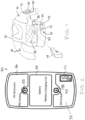
Figure 1 is a schematic representation of the electrode assembly used in cooperation with a simulated combat stress exposure training system; -
Figure 2 is a schematic representation of the electrical components within the housing of the electrode assembly; -
Figures 3 and 4 are top views of the electrode assembly in the released position and the mounted position respectively; -
Figures 5 and 6 are side views of the electrode assembly in the released position and the mounted position respectively; -
Figure 7 is a side view of the electrode assembly in the released position prior to attachment to a garment; -
Figure 8 is a side view of the electrode assembly in the mounted position attached to a garment; -
Figure 9 is a side view of the electrode assembly in the mounted position as the garment is placed onto a user; -
Figure 10 is a side view of the electrode assembly in the mounted position with the garment worn by a user such that the electrodes contact the skin of the user; -
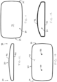
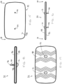
Figures 11, 12, 13, and 14 are outer, top, side and inner views respectively of the housing of the electrode assembly separated from the pad that mounts the electrodes therein; and -
Figures 15, 16, 17 and 18 are inner, top, outer, and side views respectively of the pad that mounts the electrodes therein shown separated from the housing of the electrode assembly. - In the drawings like characters of reference indicate corresponding parts in the different figures.
- Referring to the accompanying figures there is illustrated a garment supported electrode assembly generally indicated by
reference numeral 10. Theelectrode assembly 10 is particularly suited for supporting one ormore electrodes 12 relative to agarment 14 to be worn by auser 16. - The garment may be any type or shape to be worn about a portion of the body of the user, for example a shirt worn about the torso or pants worn about the legs of the user. The garment has a
fabric layer 18, for example a woven knit type material, in which the garment is worn such that an inner surface of the fabric layer faces inwardly to lie against the skin of the user and an opposing outer surface of the fabric layer is located at an external side of the garment. - In some instances, the electrodes may be used in a medical environment to acquire a biological electrical signal emitted by the body of the user. In this instance, the electrodes acquire the signal from the body of the user such that the electrode assembly can further transmit the signal to an external electrical device used to interpret the signal.
- In the illustrated embodiment, the
electrodes 12 are used together with a stress exposure training system to simulate a stress exposure environment, for example a combat simulation system. In this instance, a target device, for example avest 20 havingsignal receivers 22 thereon is worn by the user. A simulatedweapon 24 may arranged to generate a coded pulsed beam of light to simulate a projectile. Acontroller 26 on the target device determines that the user has been hit with a simulated projectile during a training exercise when thesignal receiver 22 receive the coded pulsed beam of light emitted by the simulatedweapon 24. Thecontroller 26 then generates a wireless activation signal that can be detected and received by theelectrode assembly 10 to deliver a non-injurious, but painful electrical shock to the skin of the user as described in further detail below. - In some instances,
multiple assemblies 10 may be worn on different parts of thegarment 14 in which thedifferent assemblies 10 each communicate wirelessly with a commonmain controller 26 as shown schematically inFigure 1 . Preferably, eachassembly 10 responds to a unique wireless activation signal from thecontroller 26 so as to activatedifferent assemblies 10 to deliver electrical shocks to different parts of the body based on different activation criteria stored on thecontroller 26. - In further embodiments, the
controller 26 that generates the wireless activation signal for one ormore assemblies 10 may be any type of electronic device capable of wireless communication with theassemblies 10, for example other simulated training equipment that can be triggered within a simulated environment for training, or a smartphone or tablet computer operated by an instructor monitoring the simulated environment for training. - The
electrode assembly 10 generally includes ahousing 30 arranged to be supported externally on thegarment 14 and apad 32 arranged to be supported internally on the garment. Thehousing 30 and thepad 32 are arranged to be connected to one another with thefabric layer 18 of the garment therebetween in a mounted position of the assembly, while remaining readily releasable from one another to remove the electrode assembly from the garment when no longer in use. - The
housing 30 and thepad 32 are both elongate in a lateral direction between opposing ends 34 of the assembly. Thehousing 30 includes (i) aninner surface 36 facing inwardly to engage the outer surface of the fabric layer in the mounted position and (ii) an opposingouter surface 38 opposite theinner surface 36 and that faces outwardly away from the garment. Thepad 32 similarly includes (i) aninner surface 40 facing towards the fabric layer to engage the inner surface of the fabric layer in the mounted position and (ii) an opposingouter surface 42 opposite theinner surface 40 so as to be arranged to be engaged against the skin of the user in the mounted position. - The
pad 32 of theassembly 10 comprises a flat sheet having a minimal thickness between theinner surface 36 and theouter surface 38 as compared to the length of the faces in the lateral direction and the perpendicular width of the faces between the top and bottom edges thereof. The pad may be moulded of an electrically insulating material that is non-conductive and resilient for example rubber, a plastic or other resilient materials. - Alternatively, the
pad 32 may comprise a rigid body. In this instance, the outer surface may be defined by a liner of resilient material for engagement with the skin of the user. The outer surface may be textured with ridges or grooves formed therein for better gripping relative to the skin of the user. - In the illustrated embodiment, two
electrodes 12 are commonly mounted on the single body of thepad 32 at spaced apart positions in the lateral direction. In further embodiments, asingle electrode 12 may be mounted on a single body of thepad 32 which in turn is coupled to asingle housing 30, for example in applications where a biological signal emitted from the body of the user is acquired by the electrode. In yet further embodiments, thepad 32 may comprise two separate bodies each supporting a respective electrode therein in which the two bodies are commonly mounted on asingle housing 30, for example to deliver an electrical shock through the two electrodes. - Each
electrode 12 is mounted in a protruding relationship relative to theouter surface 38 of the pad that engages the user. The exterior head of the electrode may be cone shaped so as to be tapered outwardly and away from the surface of the pad towards a central apex of the electrode. Preferably the apex has an interior angle which is greater than 90° such that the apex is not too sharp in a manner that would cause discomfort to the user but remains pointed to form a firm contact of the tip of the electrode with the skin of the user. - Each electrode includes a
first connector 44 associated therewith. In the illustrated embodiment thefirst connector 44 is a pin connector comprising a post connected to the exterior head of theelectrode 12 to extend through a corresponding mounting aperture in the pad for protruding inwardly beyond the opposinginner surface 36 of the pad. The post forming thefirst connector 44 is round in cross-sectional shape and has an outer diameter which is much smaller than the diameter of the exterior head of theelectrode 12. - The diameter of the post forming the
first connector 44 is quite small and is tapered at the free end thereof to form apointed tip 46 such that thefirst connector 44 can be readily self-penetrated through the fabric layer. When the fabric layer comprises a woven knit material with a tight weave having no visible gaps therein, the diameter of the first connector is such that the pointed tip is able to spread individual strands of the woven knit to allow passage of the first connector through the fabric in a non-destructive manner. - A
retainer catch 48 is formed at an intermediate location along the post of the first connector at a location spaced from theinner surface 36 of the pad. Thecatch 48 is formed as a recessed groove extending about the full circumference of the post to assist in retaining thepad 32 in a mounted position relative to the housing as described in further detail below. - The exterior head of the
electrode 12 and the post of thefirst connector 44 are formed as a continuous unitary body of conductive metal so that electrical signals can be communicated through thefirst connector 44 to the electrode and from the electrode through thefirst connector 44. - The
housing 30 has an outer perimeter shape which is substantially identical to the outer perimeter shape of thepad 32. Theinner side 40 that mounts against the fabric layer fully spans the length and width of the housing so as to be bound by the perimeter shape of the housing, similarly to theinner surface 36 that spans the complete interior side of thepad 32 so as to be bound by the perimeter shape of the pad. Theinner surface 40 is flat and rigid. - A perimeter wall 50 defining the perimeter shape of the housing protrudes perpendicularly outwardly about the full perimeter of the
inner surface 40. Theouter surface 42 is smooth and rounded in profile and extends continuously from the perimeter wall such that the perimeter wall and theouter face 42 collectively form a smooth, domed structure which is generally convex in shape and which is devoid of any sharp edges or corners. - The housing has a hollow interior supporting various electrical components therein. This includes a printed
circuit board 52 having a processor and a memory including programming instructions thereon which are arranged to be executed by the processor for performing the various functions of the assembly. The printed circuit board incorporates awireless transceiver 53 therein which is arranged to transmit and receive wireless electronic signals for communicating information between the controller and an external electronic device such as thecontroller 26 of the training system shown inFigure 1 , to receive an activation signal and to activate delivery of an electrical shock to the user for example. - A
battery 54 is also supported within the housing to provide electrical power to the printedcircuit board 52. A wireless charging coil may be incorporated into the power supply circuit such that the battery is arranged to be charged by induction simply by placing thehousing 30 in proximity to an induction charging unit. - An
electrical impulse device 56 is also supported within the interior of the housing in communication with thecontroller 52 to receive electrical power from thebattery 54. The electrical impulse device is also in communication with both of the electrodes in the mounted position as described in further detail below. When an activation signal with prescribed shock settings is received by thecontroller 52, the controller activates the electrical impulse device which in turn generates a high-voltage electrical signal for delivery to the electrodes to deliver a painful, yet non-injurious electrical shock to the user. - Electrical communication of the
electrodes 12 with the electrical impulse device, as well as structural mounting of thepad 32 relative to the housing is accomplished by a pair ofsecond connectors 58. Eachsecond connector 58 is supported on the housing at the inner side thereof in alignment with a respective one of thefirst connectors 44. Thesecond connectors 58 are thus laterally spaced apart from one another by a similar spacing as thefirst connectors 44. Thesecond connectors 58 are also positioned relative to the perimeter shape of the housing in a similar manner as thefirst connectors 44 relative to the perimeter shape of the pad such that alignment of the perimeter shapes of the housing and pad in the mounted position is sufficient to align eachfirst connector 44 with the correspondingsecond connector 58. - Each
second connector 58 is a socket connector which is arranged to receive a respective one of the pin connectors of the first connector therein in the mounted position. The socket is formed of a conductive material and is tubular in shape, having an interior diameter which is very similar to the outer diameter of the post of the respectivefirst connector 44. The post of thefirst connector 44 may be sized for a slight interference fit relative to the socket of the correspondingsecond connector 58 to ensure that the first connector is frictionally retained within the second connector in the mounted position while remaining releasable if the friction forces are overcome by a user pulling the pad and housing apart from one another. - A locking protrusion 60 is supported within each
socket connector 58 to protrude inwardly beyond the inner diameter thereof for alignment with thecatch 48 on the correspondingfirst connector 44. The protrusion 60 is preferably resiliently supported relative to the socket such that the protrusion can be flexed outwardly in non-interference with the interior diameter of thesecond connector 58 as the first connector is inserted therein; however, the protrusion 60 is biased into the interior space of the socket for insertion into the recessed groove of thecatch 48 once the pad and housing are in the mounted position relative to one another. In this manner, thefirst connector 44 forms a snap-fit connection into the corresponding second connector. - The conductive material forming the tubular socket of each second connector is electrically and conductively connected to the electrical impulse device and the printed circuit board such that the electrical signal representing the impulse shock to be delivered to the user can be transmitted directly from the components within the housing to the
electrodes 12 in contact with the skin of the user in the mounted position of the assembly. - The
electrode assembly 10 as described herein can be used with a variety of different garments and thepin connectors 44 which are penetrated through the fabric material of the garment have a small diameter and a pointed tip for ease of penetration between the knit fibers of the fabric even when no visible holes are provided in the fabric, without causing any damage to the fabric. - The
pad 32 is intended to be supported at the inner surface of the fabric layer while the housing is mounted at the outer surface. Once thefirst connectors 44 are penetrated through the fabric layer and inserted into the corresponding second connectors of the housing, the housing is ready for pairing with an additional electronic device, for example (i) acontroller 26 of the combat simulation system described above, or (ii) in the instance of medical electrodes, other external medical equipment capable of interpreting biologically emitted electrical signals captured by the electrodes. In the illustrated embodiment, when a pulsed signal hits the sensor of the target device such that thecontroller 26 generates an activation signal transmitted wirelessly to thecontroller 52 of the electrode assembly, thecontroller 52 of theelectrode assembly 10 activates the electrical impulse device to generate an electrical signal delivered to the electrodes which causes an electrical shock to be delivered to the user. - When use is no longer required, the electrode assembly can be removed from the garment by overcoming the retention forces of the
first connectors 44 received within thesecond connectors 58 and the retention force of the resiliently supported locking protrusions 60 to separate the pad and housing from one another for subsequent removal from the fabric material. When using the assembly with the new user, thepad 32 supporting theelectrodes 12 thereon which contacts the user can be simply replaced and the housing containing the various electrical components noted above can be reused with adifferent pad 32 interchanged thereon while similarly supporting the assembly on a new garments associated with the new user. The simplicity of interchanging thepad 32 minimizes the amount of sanitation required between different uses on different users as the externally supported housing requires thorough cleaning between uses. - Since various modifications can be made in my invention as herein above described, and many apparently widely different embodiments of same made, it is intended that all matter contained in the accompanying specification shall be interpreted as illustrative only and not in a limiting sense and that the scope of protection of the present invention is only defined by the appended claims.
Claims (14)
- An electrode assembly (10) for attachment to a garment (14) worn by a user (16), the garment (14) having a fabric layer with an inner surface supported against the user (16) and an outer surface opposite the inner surface at an exterior of the garment (14), the electrode assembly (10) comprising:at least one electrode (12) arranged to directly contact the user (16);a first connector (44) associated with said at least one electrode (12);a housing (30) arranged to be supported externally against the outer surface of the fabric layer, the housing (30) including an electronic component therein;a second connector (58) supported on the housing (30) in association with the first connector (44);one of the first connector (44) and the second connector (58) comprising a pin connector and another one of the first connector (44) and the second connector (58) comprising a socket connector; andsaid at least one electrode (12) and the electronic component being in electrical communication with one another in the mounted position so as to be arranged to communicate an electrical signal between said at least one electrode (12) and the electronic component on the housing (30) in the mounted position;characterized by:a pad (32) supports said at least one electrode (12) thereon wherein the pad (32) is arranged for mounting against the inner surface of the fabric layer;the first connector (44) is supported on the pad (32);the socket connector is arranged to receive the pin connector therein to releasably attach the housing (30) to the pad (32) in a mounted position of the assembly;the pin connector is shaped to be self-penetrating through the fabric layer in a non-destructive manner so as to be arranged for insertion through the fabric layer between the pad (32) at the inner surface and the housing (30) at the outer surface in the mounted position; andthe electronic component of the housing (30) includes an electrical impulse device supported on the housing (30) in communication with said at least one electrode (12) so as to be arranged to deliver an electrical impulse to the user (16) through said at least one electrode (12) that causes non-injurious pain to the user (16).
- The assembly (10) according to claim 1 wherein the pin connector includes a recess formed therein defining a catch (48) arranged to be engaged by the socket connector.
- The assembly (10) according to claim 2 wherein the recess comprises an annular groove extending about a circumference of the pin connector.
- The assembly (10) according to any one of claims 1 through 3 wherein the pin connector and the socket connector are formed of conductive material defining a conductive path arranged to communicate the electrical signal between said at least one electrode (12) and the electronic component on the housing (30) in the mounted position.
- The assembly (10) according to any one of claims 1 through 4 wherein said at least one electrode (12) is conical in shape so as to be tapered outwardly from the pad (32) towards an apex.
- The assembly (10) according to any one of claims 1 through 5 wherein said at least one electrode (12) comprises a pair of electrodes (12), each electrode (12) having a respective first connector (44) associated therewith which connects the electrode (12) to the electronic component of the housing (30).
- The assembly (10) according to claim 6 wherein the pad (32) comprises a single body commonly supporting both electrodes (12) therein.
- The assembly (10) according to any one of claims 1 through 7 wherein the pad (32) has an outer surface for engaging the user (16), the outer surface being formed of a resilient material.
- The assembly (10) according to any one of claims 1 through 8 wherein the pad (32) has an outer surface for engaging the user (16), the outer surface being textured for gripping the user (16).
- The assembly (10) according to any one of claims 1 through 9 wherein the pad (32) has an outer surface for engaging the user (16), the outer surface being formed of a non-conductive, electrically insulating material.
- The assembly (10) according to any one of claims 1 through 10 further comprising a battery supported on the housing (30) so as to be arranged to deliver an electrical signal from the housing (30) to the user (16) through said at least one electrode (12).
- The assembly (10) according to any one of claims 1 through 11 wherein(i) the housing (30) has an inner surface (36) for abutment against the fabric layer bound by a prescribed perimeter shape of the housing (30),(ii) the pad (32) has an inner surface (40) for abutment against the fabric layer bound by a prescribed perimeter shape of the pad (32), and(iii) the prescribed perimeter shape of the housing (30) and the prescribed perimeter shape of the pad (32) being substantially identical to one another.
- The assembly (10) according to any one of claims 1 through 12 wherein the electronic component of the housing (30) includes(i) a controller having a processor and a memory storing programming instructions arranged to be executed by the processor, and(ii) a transceiver connected to the controller so as to be arranged to communicate signals wirelessly between the controller and an external electronic device.
- The assembly (10) according to any one of claims 1 through 13 wherein the electrical component of the housing (30) is arranged to(i) receive a biological signal that is (a) emitted by a body of the user (16) and (b) acquired by said at least one electrode (12), and(ii) transmit the biological signal to an external electronic device.
Applications Claiming Priority (2)
| Application Number | Priority Date | Filing Date | Title |
|---|---|---|---|
| US16/880,011 US11380212B2 (en) | 2020-05-21 | 2020-05-21 | Garment supported electrode |
| PCT/CA2021/050295 WO2021232140A1 (en) | 2020-05-21 | 2021-03-05 | Garment supported electrode |
Publications (4)
| Publication Number | Publication Date |
|---|---|
| EP4153934A1 EP4153934A1 (en) | 2023-03-29 |
| EP4153934A4 EP4153934A4 (en) | 2024-05-08 |
| EP4153934C0 EP4153934C0 (en) | 2025-06-04 |
| EP4153934B1 true EP4153934B1 (en) | 2025-06-04 |
Family
ID=78608278
Family Applications (1)
| Application Number | Title | Priority Date | Filing Date |
|---|---|---|---|
| EP21808056.2A Active EP4153934B1 (en) | 2020-05-21 | 2021-03-05 | Garment supported electrode |
Country Status (6)
| Country | Link |
|---|---|
| US (1) | US11380212B2 (en) |
| EP (1) | EP4153934B1 (en) |
| KR (1) | KR20230010628A (en) |
| CA (1) | CA3176746A1 (en) |
| IL (1) | IL298408B2 (en) |
| WO (1) | WO2021232140A1 (en) |
Families Citing this family (2)
| Publication number | Priority date | Publication date | Assignee | Title |
|---|---|---|---|---|
| US12332026B2 (en) | 2017-07-31 | 2025-06-17 | Compliant Technologies Llc | Device deterring movement of a detainee |
| JP2024103351A (en) * | 2023-01-20 | 2024-08-01 | マクセル株式会社 | Treatment Equipment |
Family Cites Families (7)
| Publication number | Priority date | Publication date | Assignee | Title |
|---|---|---|---|---|
| US3841312A (en) | 1973-03-29 | 1974-10-15 | Cons Med Equip | Electrode arrangement |
| JP2009160091A (en) | 2007-12-28 | 2009-07-23 | Nec Corp | Bioelectric signal measuring apparatus |
| US9489857B2 (en) * | 2010-12-09 | 2016-11-08 | Jeffrey James Quail | Controller for electrical impulse stress exposure training |
| US9055879B2 (en) * | 2013-06-14 | 2015-06-16 | Suunto Oy | Device and method for assembling an electronic device and a flexible element for facilitating assembly of electronic components |
| US9218730B2 (en) | 2014-02-26 | 2015-12-22 | Tyco Fire & Security Gmbh | Security tag with magnetic gate |
| US10874351B2 (en) * | 2015-03-20 | 2020-12-29 | Zentan Technology Co., Ltd. | Physiological signal detecting apparatus and physiological signal detecting device |
| WO2017007021A1 (en) | 2015-07-08 | 2017-01-12 | 日本電信電話株式会社 | Biomedical electrode and wearable electrode |
-
2020
- 2020-05-21 US US16/880,011 patent/US11380212B2/en active Active
-
2021
- 2021-03-05 CA CA3176746A patent/CA3176746A1/en active Pending
- 2021-03-05 IL IL298408A patent/IL298408B2/en unknown
- 2021-03-05 EP EP21808056.2A patent/EP4153934B1/en active Active
- 2021-03-05 WO PCT/CA2021/050295 patent/WO2021232140A1/en not_active Ceased
- 2021-03-05 KR KR1020227037584A patent/KR20230010628A/en active Pending
Also Published As
| Publication number | Publication date |
|---|---|
| US20210366305A1 (en) | 2021-11-25 |
| US11380212B2 (en) | 2022-07-05 |
| EP4153934C0 (en) | 2025-06-04 |
| EP4153934A4 (en) | 2024-05-08 |
| WO2021232140A1 (en) | 2021-11-25 |
| KR20230010628A (en) | 2023-01-19 |
| IL298408B2 (en) | 2026-05-01 |
| CA3176746A1 (en) | 2021-11-25 |
| EP4153934A1 (en) | 2023-03-29 |
| IL298408A (en) | 2023-01-01 |
| IL298408B1 (en) | 2026-01-01 |
Similar Documents
| Publication | Publication Date | Title |
|---|---|---|
| EP3731922B1 (en) | Communication devices, methods, and systems | |
| EP2588187B1 (en) | Disposable electrode for electro-stimulation | |
| US11380212B2 (en) | Garment supported electrode | |
| EP2575955B1 (en) | Electrode assembly with magnetic connection | |
| US6338347B1 (en) | Blood circulation stimulator | |
| US10629084B2 (en) | Tactical injury simulating training device | |
| EP2603135A1 (en) | Ecg hand-held device | |
| KR20150097719A (en) | Method and apparatus to increase tactile sensitivity and proprioception in humans | |
| US12178579B1 (en) | Sensor for monitoring posture | |
| US9545213B2 (en) | Electrode patch and physiological signal device | |
| ES2237532T3 (en) | ELECTRODE POSITIONER FOR A USEFUL FERULA IN MUSCULAR STIMULATION. | |
| WO2013142785A4 (en) | Noninvasive delivery and control of stimulation signals | |
| US8131381B1 (en) | Electrotherapeutic device having an electrode array | |
| EP3946035B1 (en) | Physiological signal collection electrodes and performance monitoring apparatus comprising same | |
| JP5224510B2 (en) | Electrical stimulator equipment and electrical stimulator set | |
| RU2857987C1 (en) | System for conducting electrocardiographic examination in continuous monitoring mode | |
| EP2433561B1 (en) | Garment with three-dimensional wearable electrode set | |
| CN213215374U (en) | Business suit with reminding function | |
| US12332026B2 (en) | Device deterring movement of a detainee | |
| JP2024178536A (en) | EMG measuring unit and EMG measuring device | |
| CN207640400U (en) | The heart rate band of perceptible feedback can be provided according to heart rate value | |
| JP6132307B2 (en) | Waterproof cover and waterproof communication set | |
| CN116271519A (en) | Electrode assembly, positioning assembly and wearable electric stimulation system | |
| NZ756368A (en) | Intra-uterine monitoring system | |
| KR20210083553A (en) | electrocardiogram measuring patch for smart clothes using conductive yarn |
Legal Events
| Date | Code | Title | Description |
|---|---|---|---|
| STAA | Information on the status of an ep patent application or granted ep patent |
Free format text: STATUS: THE INTERNATIONAL PUBLICATION HAS BEEN MADE |
|
| PUAI | Public reference made under article 153(3) epc to a published international application that has entered the european phase |
Free format text: ORIGINAL CODE: 0009012 |
|
| STAA | Information on the status of an ep patent application or granted ep patent |
Free format text: STATUS: REQUEST FOR EXAMINATION WAS MADE |
|
| 17P | Request for examination filed |
Effective date: 20221102 |
|
| AK | Designated contracting states |
Kind code of ref document: A1 Designated state(s): AL AT BE BG CH CY CZ DE DK EE ES FI FR GB GR HR HU IE IS IT LI LT LU LV MC MK MT NL NO PL PT RO RS SE SI SK SM TR |
|
| DAV | Request for validation of the european patent (deleted) | ||
| DAX | Request for extension of the european patent (deleted) | ||
| A4 | Supplementary search report drawn up and despatched |
Effective date: 20240408 |
|
| RIC1 | Information provided on ipc code assigned before grant |
Ipc: F41A 33/02 20060101ALI20240402BHEP Ipc: A61B 5/00 20060101ALI20240402BHEP Ipc: G09B 9/00 20060101ALI20240402BHEP Ipc: F41H 13/00 20060101AFI20240402BHEP |
|
| GRAP | Despatch of communication of intention to grant a patent |
Free format text: ORIGINAL CODE: EPIDOSNIGR1 |
|
| STAA | Information on the status of an ep patent application or granted ep patent |
Free format text: STATUS: GRANT OF PATENT IS INTENDED |
|
| INTG | Intention to grant announced |
Effective date: 20250219 |
|
| GRAS | Grant fee paid |
Free format text: ORIGINAL CODE: EPIDOSNIGR3 |
|
| GRAA | (expected) grant |
Free format text: ORIGINAL CODE: 0009210 |
|
| STAA | Information on the status of an ep patent application or granted ep patent |
Free format text: STATUS: THE PATENT HAS BEEN GRANTED |
|
| AK | Designated contracting states |
Kind code of ref document: B1 Designated state(s): AL AT BE BG CH CY CZ DE DK EE ES FI FR GB GR HR HU IE IS IT LI LT LU LV MC MK MT NL NO PL PT RO RS SE SI SK SM TR |
|
| REG | Reference to a national code |
Ref country code: GB Ref legal event code: FG4D |
|
| REG | Reference to a national code |
Ref country code: CH Ref legal event code: EP |
|
| REG | Reference to a national code |
Ref country code: DE Ref legal event code: R096 Ref document number: 602021031893 Country of ref document: DE |
|
| REG | Reference to a national code |
Ref country code: IE Ref legal event code: FG4D |
|
| U01 | Request for unitary effect filed |
Effective date: 20250701 |
|
| U07 | Unitary effect registered |
Designated state(s): AT BE BG DE DK EE FI FR IT LT LU LV MT NL PT RO SE SI Effective date: 20250707 |
|
| PG25 | Lapsed in a contracting state [announced via postgrant information from national office to epo] |
Ref country code: ES Free format text: LAPSE BECAUSE OF FAILURE TO SUBMIT A TRANSLATION OF THE DESCRIPTION OR TO PAY THE FEE WITHIN THE PRESCRIBED TIME-LIMIT Effective date: 20250604 |
|
| PG25 | Lapsed in a contracting state [announced via postgrant information from national office to epo] |
Ref country code: NO Free format text: LAPSE BECAUSE OF FAILURE TO SUBMIT A TRANSLATION OF THE DESCRIPTION OR TO PAY THE FEE WITHIN THE PRESCRIBED TIME-LIMIT Effective date: 20250904 Ref country code: GR Free format text: LAPSE BECAUSE OF FAILURE TO SUBMIT A TRANSLATION OF THE DESCRIPTION OR TO PAY THE FEE WITHIN THE PRESCRIBED TIME-LIMIT Effective date: 20250905 |
|
| PG25 | Lapsed in a contracting state [announced via postgrant information from national office to epo] |
Ref country code: PL Free format text: LAPSE BECAUSE OF FAILURE TO SUBMIT A TRANSLATION OF THE DESCRIPTION OR TO PAY THE FEE WITHIN THE PRESCRIBED TIME-LIMIT Effective date: 20250604 |
|
| PG25 | Lapsed in a contracting state [announced via postgrant information from national office to epo] |
Ref country code: HR Free format text: LAPSE BECAUSE OF FAILURE TO SUBMIT A TRANSLATION OF THE DESCRIPTION OR TO PAY THE FEE WITHIN THE PRESCRIBED TIME-LIMIT Effective date: 20250604 |
|
| PG25 | Lapsed in a contracting state [announced via postgrant information from national office to epo] |
Ref country code: RS Free format text: LAPSE BECAUSE OF FAILURE TO SUBMIT A TRANSLATION OF THE DESCRIPTION OR TO PAY THE FEE WITHIN THE PRESCRIBED TIME-LIMIT Effective date: 20250904 |
|
| PG25 | Lapsed in a contracting state [announced via postgrant information from national office to epo] |
Ref country code: IS Free format text: LAPSE BECAUSE OF FAILURE TO SUBMIT A TRANSLATION OF THE DESCRIPTION OR TO PAY THE FEE WITHIN THE PRESCRIBED TIME-LIMIT Effective date: 20251004 |
|
| PG25 | Lapsed in a contracting state [announced via postgrant information from national office to epo] |
Ref country code: SM Free format text: LAPSE BECAUSE OF FAILURE TO SUBMIT A TRANSLATION OF THE DESCRIPTION OR TO PAY THE FEE WITHIN THE PRESCRIBED TIME-LIMIT Effective date: 20250604 |
|
| PG25 | Lapsed in a contracting state [announced via postgrant information from national office to epo] |
Ref country code: CZ Free format text: LAPSE BECAUSE OF FAILURE TO SUBMIT A TRANSLATION OF THE DESCRIPTION OR TO PAY THE FEE WITHIN THE PRESCRIBED TIME-LIMIT Effective date: 20250604 |
|
| PG25 | Lapsed in a contracting state [announced via postgrant information from national office to epo] |
Ref country code: SK Free format text: LAPSE BECAUSE OF FAILURE TO SUBMIT A TRANSLATION OF THE DESCRIPTION OR TO PAY THE FEE WITHIN THE PRESCRIBED TIME-LIMIT Effective date: 20250604 |
|
| PGFP | Annual fee paid to national office [announced via postgrant information from national office to epo] |
Ref country code: GB Payment date: 20260324 Year of fee payment: 6 |
|
| PLBE | No opposition filed within time limit |
Free format text: ORIGINAL CODE: 0009261 |
|
| STAA | Information on the status of an ep patent application or granted ep patent |
Free format text: STATUS: NO OPPOSITION FILED WITHIN TIME LIMIT |
|
| REG | Reference to a national code |
Ref country code: CH Ref legal event code: L10 Free format text: ST27 STATUS EVENT CODE: U-0-0-L10-L00 (AS PROVIDED BY THE NATIONAL OFFICE) Effective date: 20260416 |
|
| U20 | Renewal fee for the european patent with unitary effect paid |
Year of fee payment: 6 Effective date: 20260326 |
|
| 26N | No opposition filed |
Effective date: 20260305 |