EP4153928B1 - Dämpferhalter - Google Patents
Dämpferhalter Download PDFInfo
- Publication number
- EP4153928B1 EP4153928B1 EP21724001.9A EP21724001A EP4153928B1 EP 4153928 B1 EP4153928 B1 EP 4153928B1 EP 21724001 A EP21724001 A EP 21724001A EP 4153928 B1 EP4153928 B1 EP 4153928B1
- Authority
- EP
- European Patent Office
- Prior art keywords
- buffer
- retainer
- hole
- channel
- lower receiver
- Prior art date
- Legal status (The legal status is an assumption and is not a legal conclusion. Google has not performed a legal analysis and makes no representation as to the accuracy of the status listed.)
- Active
Links
Images


Classifications
-
- F—MECHANICAL ENGINEERING; LIGHTING; HEATING; WEAPONS; BLASTING
- F41—WEAPONS
- F41A—FUNCTIONAL FEATURES OR DETAILS COMMON TO BOTH SMALLARMS AND ORDNANCE, e.g. CANNONS; MOUNTINGS FOR SMALLARMS OR ORDNANCE
- F41A3/00—Breech mechanisms, e.g. locks
- F41A3/64—Mounting of breech-blocks; Accessories for breech-blocks or breech-block mountings
- F41A3/78—Bolt buffer or recuperator means
- F41A3/82—Coil spring buffers
-
- F—MECHANICAL ENGINEERING; LIGHTING; HEATING; WEAPONS; BLASTING
- F41—WEAPONS
- F41A—FUNCTIONAL FEATURES OR DETAILS COMMON TO BOTH SMALLARMS AND ORDNANCE, e.g. CANNONS; MOUNTINGS FOR SMALLARMS OR ORDNANCE
- F41A3/00—Breech mechanisms, e.g. locks
- F41A3/64—Mounting of breech-blocks; Accessories for breech-blocks or breech-block mountings
- F41A3/78—Bolt buffer or recuperator means
-
- F—MECHANICAL ENGINEERING; LIGHTING; HEATING; WEAPONS; BLASTING
- F41—WEAPONS
- F41A—FUNCTIONAL FEATURES OR DETAILS COMMON TO BOTH SMALLARMS AND ORDNANCE, e.g. CANNONS; MOUNTINGS FOR SMALLARMS OR ORDNANCE
- F41A3/00—Breech mechanisms, e.g. locks
- F41A3/64—Mounting of breech-blocks; Accessories for breech-blocks or breech-block mountings
- F41A3/66—Breech housings or frames; Receivers
-
- F—MECHANICAL ENGINEERING; LIGHTING; HEATING; WEAPONS; BLASTING
- F41—WEAPONS
- F41A—FUNCTIONAL FEATURES OR DETAILS COMMON TO BOTH SMALLARMS AND ORDNANCE, e.g. CANNONS; MOUNTINGS FOR SMALLARMS OR ORDNANCE
- F41A3/00—Breech mechanisms, e.g. locks
- F41A3/64—Mounting of breech-blocks; Accessories for breech-blocks or breech-block mountings
- F41A3/78—Bolt buffer or recuperator means
- F41A3/82—Coil spring buffers
- F41A3/84—Coil spring buffers mounted within the gun stock
Definitions
- the present invention relates to a buffer retainer system for an automatic or semi-automatic weapon with a buffer system, which buffer retainer system keeps the buffer inside a buffer tube when the weapon is dismantled.
- Buffer systems in weapons are designed to work together and assist a bolt carrier when it moves during the operation of the weapon.
- the buffer systems are typically formed and connected to the rear end of a lower receiver of the weapon, wherein the buffer contacts the rear end of the bolt carrier.
- the buffer moves first backwards with the bolt carrier and then pushes the bolt carrier forward, which back-and forth movement typically achieves the required bolt action of an automatic or semi-automatic rifle.
- the buffer system typically comprises a buffer tube, which is closed at rear end and open at front end, the buffer itself, and a spring, and the buffer with the spring are inside the buffer tube so, that the spring is located at least partially between the buffer and the closed end of the buffer tube.
- the buffer tube is typically connected to a rear of a lower receiver of a weapon via an opening formed in the lower receiver for the buffer tube with a threaded connection.
- the lower receiver is also equipped with a buffer retainer, which is typically a movable pin extending from the surface of the opening formed in the rear receiver for the buffer tube, and which buffer retainer prevents the spring loaded buffer to exit from the buffer tube.
- the buffer retainer is typically located in a hole formed in the rear portion of the lower receiver.
- the hole opens partially in the area, or close to the edge of the area, of the fixing surface formed in the rear receiver for fixing the buffer tube, which fixing surface is typically formed with threading.
- the buffer retainer is formed as a longitudinal cylindrical piece having a smaller diameter section and a larger diameter section and a circular beveled shoulder between the sections.
- a spring In the hole between the bottom of the hole and the buffer retainer is placed a spring. After the spring and the buffer retainer are placed in the hole, the buffer retainer is pushed downwards and the buffer tube is moved partially cover the hole so, that the beveled shoulder is at least partially under the edge of the buffer tube.
- Publication US 2016/0209137 A1 discloses a bolt carrier support system, wherein buffer retention system may comprise a body, a retention tab and a spring, which body comprises a partially annual guide portion with a channel for the retention tab.
- Publication US 8,991,088 B1 discloses a folding buttstock for firearms with recoil assemblies contained within the buttstock with buffer retainer system.
- the present invention as defined by claim 1 provides a novel buffer retainer system, which maintains its position in the rear receiver when the weapon is dismantled. Further, the present invention provides buffer retainer system which is easy to assemble in the lower receiver of the weapon and wherein the channels formed for the buffer retainer system does not collect dirt so easily as the prior art solutions. The present invention also allows for more compact structure of the lower receiver, which lowers the overall weight of the weapon itself.
- the present invention provides a buffer retainer system, which system comprises a buffer retainer and a retainer spring set in a hole formed in a lower receiver of an AR-type weapon, and wherein the buffer retainer comprises a body portion having an upper surface, and a retainer tab extending from the upper surface of the body portion and configured to extend above a surface of the lower receiver to restrict movement of a buffer of the weapon, wherein the lower receiver comprises a channel extending between the end surface of the hole and the said surface of the lower receiver, and which channel has smaller diameter than the said hole, and that the retainer tab of the buffer retainer is configured to extend via the channel in the hole.
- the longitudinal center axis of the said hole and the said channel are parallel but not concentric.
- This provides eccentric positioning of the retainer tab on the upper surface of the body portion which helps in the assembly of the buffer retainer in the lower receiver and prevents the buffer retainer rotating during the operation of the weapon.
- the said hole and the said channel extend substantially perpendicularly in relation to the said surface of the lower receiver of the weapon. This is a preferred embodiment, but alternatively the hole and channel can also be formed to extent non-perpendicularly if deemed necessary.
- FIG. 2 shows schematically an embodiment of a buffer retainer 5 of the invention.
- the buffer retainer 5 comprises a body portion 6, and a retainer tab 7 extending from the top surface of the body portion.
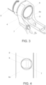
- Figure 5 illustrates the situation where a bolt carrier 10 presses against the buffer 9 at its rearmost position due to firing of the weapon or due to manual loading movement of the weapon.
- the bolt carrier 10 In this position the bolt carrier 10 is moved inside the buffer tube 3 and passed the retainer tab 7 of the buffer retainer 5.
- the buffer spring 11 In the bottom surface of the bolt carrier 10 is formed a continuous groove so that the bolt carrier can pass the retainer tab 7 without contacting it.
- the buffer spring 11 will push the buffer 9 and the bolt carrier forward, which forward movement of the buffer is stopped with the retainer tab 7 as shown in figure 6 .
Landscapes
- Engineering & Computer Science (AREA)
- General Engineering & Computer Science (AREA)
- Vibration Dampers (AREA)
- Aiming, Guidance, Guns With A Light Source, Armor, Camouflage, And Targets (AREA)
Claims (5)
- Pufferhaltersystem für eine Waffe (1), wobei das System einen unteren Empfänger (4) eines AR-Gewehrs, einen Pufferhalter (5) und eine Haltefeder (12) umfasst, die beide in einem Loch (14) eingesetzt sind, das im unteren Empfänger (4) ausgebildet ist, und wobei der Pufferhalter einen Körperabschnitt (6) mit einer oberen Oberfläche und eine Haltelasche (7) umfasst, die von der oberen Oberfläche des Körperabschnitts ausgeht und so konfiguriert ist, dass sie über eine Oberfläche (4a) des unteren Empfängers hinausragt, um die Bewegung eines Puffers (9) der Waffe einzuschränken, wobei der untere Empfänger (4) einen Kanal (15) umfasst, der im unteren Empfänger ausgebildet ist und zwischen der Endoberfläche des Lochs (14) und der besagten Oberfläche (4a) des unteren Empfängers (4) verläuft, und der Kanal einen kleineren Durchmesser als das besagte Loch hat, und dass die Haltelasche (7) des Pufferhalters (5) so konfiguriert ist, dass sie über den Kanal im Loch hinausragt.
- Pufferhaltersystem nach Anspruch 1, wobei das System eine Halteschraube (13) zum Halten der Feder (12) und des Pufferhalters (5) innerhalb des Lochs (14) umfasst.
- Pufferhaltersystem nach Anspruch 1 oder 2, wobei die Längsmittelachsen des Lochs (14) und des Kanals (15) parallel, aber nicht konzentrisch sind.
- Pufferhaltesystem nach einem der Ansprüche 1 bis 3, wobei das Loch (14) und der Kanal (15) im Wesentlichen senkrecht zur Oberfläche (4a) des unteren Empfängers (4) verlaufen.
- Pufferhaltesystem nach einem der Ansprüche 1 bis 4, wobei die Öffnung des Kanals (15) auf der Oberfläche (4a) des unteren Empfängers (4) in unmittelbarer Nähe einer Gewindebefestigungsfläche liegt, die im unteren Empfänger (4) für ein Pufferrohr (3) ausgebildet ist.
Priority Applications (2)
| Application Number | Priority Date | Filing Date | Title |
|---|---|---|---|
| HRP20250798TT HRP20250798T1 (hr) | 2020-05-20 | 2021-04-30 | Zadrživač amortizera |
| RS20250661A RS66983B1 (sr) | 2020-05-20 | 2021-04-30 | Držač pufera |
Applications Claiming Priority (2)
| Application Number | Priority Date | Filing Date | Title |
|---|---|---|---|
| FI20205512A FI129338B (en) | 2020-05-20 | 2020-05-20 | Buffer arrested |
| PCT/FI2021/050325 WO2021234215A1 (en) | 2020-05-20 | 2021-04-30 | Buffer retainer |
Publications (3)
| Publication Number | Publication Date |
|---|---|
| EP4153928A1 EP4153928A1 (de) | 2023-03-29 |
| EP4153928B1 true EP4153928B1 (de) | 2025-04-09 |
| EP4153928C0 EP4153928C0 (de) | 2025-04-09 |
Family
ID=75850216
Family Applications (1)
| Application Number | Title | Priority Date | Filing Date |
|---|---|---|---|
| EP21724001.9A Active EP4153928B1 (de) | 2020-05-20 | 2021-04-30 | Dämpferhalter |
Country Status (10)
| Country | Link |
|---|---|
| US (1) | US12130107B2 (de) |
| EP (1) | EP4153928B1 (de) |
| AU (1) | AU2021276578A1 (de) |
| CA (1) | CA3177542A1 (de) |
| ES (1) | ES3025972T3 (de) |
| FI (1) | FI129338B (de) |
| HR (1) | HRP20250798T1 (de) |
| PL (1) | PL4153928T3 (de) |
| RS (1) | RS66983B1 (de) |
| WO (1) | WO2021234215A1 (de) |
Family Cites Families (4)
| Publication number | Priority date | Publication date | Assignee | Title |
|---|---|---|---|---|
| US8991088B1 (en) | 2011-11-17 | 2015-03-31 | CQ Innovations, Inc. | Folding buttstock for firearms with recoil assemblies contained within the buttstock |
| US10012462B2 (en) * | 2015-01-20 | 2018-07-03 | Patriot Ordnance Factory, Inc. | Bolt carrier support system |
| US10197347B2 (en) * | 2016-09-12 | 2019-02-05 | Paul Leitner-Wise | Buffer retaining pin |
| WO2019036687A1 (en) | 2017-08-17 | 2019-02-21 | Miller Michael D | SYSTEM AND METHOD FOR FIREARM ASSEMBLY |
-
2020
- 2020-05-20 FI FI20205512A patent/FI129338B/en active IP Right Grant
-
2021
- 2021-04-30 RS RS20250661A patent/RS66983B1/sr unknown
- 2021-04-30 HR HRP20250798TT patent/HRP20250798T1/hr unknown
- 2021-04-30 US US17/925,210 patent/US12130107B2/en active Active
- 2021-04-30 WO PCT/FI2021/050325 patent/WO2021234215A1/en not_active Ceased
- 2021-04-30 AU AU2021276578A patent/AU2021276578A1/en active Pending
- 2021-04-30 CA CA3177542A patent/CA3177542A1/en active Pending
- 2021-04-30 PL PL21724001.9T patent/PL4153928T3/pl unknown
- 2021-04-30 EP EP21724001.9A patent/EP4153928B1/de active Active
- 2021-04-30 ES ES21724001T patent/ES3025972T3/es active Active
Also Published As
| Publication number | Publication date |
|---|---|
| HRP20250798T1 (hr) | 2025-09-12 |
| ES3025972T3 (en) | 2025-06-10 |
| AU2021276578A1 (en) | 2022-12-08 |
| US20230228506A1 (en) | 2023-07-20 |
| US12130107B2 (en) | 2024-10-29 |
| WO2021234215A1 (en) | 2021-11-25 |
| FI129338B (en) | 2021-12-15 |
| PL4153928T3 (pl) | 2025-08-18 |
| FI20205512A1 (en) | 2021-11-21 |
| EP4153928A1 (de) | 2023-03-29 |
| RS66983B1 (sr) | 2025-07-31 |
| CA3177542A1 (en) | 2021-11-25 |
| EP4153928C0 (de) | 2025-04-09 |
Similar Documents
| Publication | Publication Date | Title |
|---|---|---|
| US7677150B2 (en) | Mounting system for muzzle devices and firearms | |
| US7886473B2 (en) | Stocks and casing for a rifle | |
| US9921019B2 (en) | Gas vent for firearm | |
| US20060236582A1 (en) | Monolithic rail platform and bolt assemblies for a firearm | |
| US12163751B2 (en) | Muzzle device for a firearm | |
| US11340029B2 (en) | Rifle with hybrid receiver, modified trunnion, gas block and ambidextrous bolt stop | |
| US12163753B2 (en) | Firearm with combined bolt catch and ejector | |
| US10697722B2 (en) | Side-charging upper for AR style firearm | |
| AU2018271301B2 (en) | Bolt carrier bearing tube for rifle receiver | |
| EP2409108A1 (de) | Festgeklemmter gasblock für lauf | |
| KR100539880B1 (ko) | 자동 권총용 장전 표시기 | |
| EP4153928B1 (de) | Dämpferhalter | |
| US12092416B1 (en) | Delayed blowback device | |
| US3336691A (en) | Firearm | |
| US20240053119A1 (en) | Forward charging handle for firearm and method therefore. | |
| US20110099868A1 (en) | Losok Valkyr Rifle | |
| US12181243B1 (en) | Side-mounted forward charging system for a firearm | |
| WO2023211504A2 (en) | Firearm with combined bolt catch and ejector | |
| WO2000001999A1 (en) | Locking a bolt action - barrel connection | |
| HK1254541B (en) | Bolt carrier bearing tube for rifle receiver |
Legal Events
| Date | Code | Title | Description |
|---|---|---|---|
| REG | Reference to a national code |
Ref country code: HR Ref legal event code: TUEP Ref document number: P20250798T Country of ref document: HR |
|
| STAA | Information on the status of an ep patent application or granted ep patent |
Free format text: STATUS: UNKNOWN |
|
| STAA | Information on the status of an ep patent application or granted ep patent |
Free format text: STATUS: THE INTERNATIONAL PUBLICATION HAS BEEN MADE |
|
| PUAI | Public reference made under article 153(3) epc to a published international application that has entered the european phase |
Free format text: ORIGINAL CODE: 0009012 |
|
| STAA | Information on the status of an ep patent application or granted ep patent |
Free format text: STATUS: REQUEST FOR EXAMINATION WAS MADE |
|
| 17P | Request for examination filed |
Effective date: 20221028 |
|
| AK | Designated contracting states |
Kind code of ref document: A1 Designated state(s): AL AT BE BG CH CY CZ DE DK EE ES FI FR GB GR HR HU IE IS IT LI LT LU LV MC MK MT NL NO PL PT RO RS SE SI SK SM TR |
|
| DAV | Request for validation of the european patent (deleted) | ||
| DAX | Request for extension of the european patent (deleted) | ||
| STAA | Information on the status of an ep patent application or granted ep patent |
Free format text: STATUS: EXAMINATION IS IN PROGRESS |
|
| 17Q | First examination report despatched |
Effective date: 20240124 |
|
| GRAP | Despatch of communication of intention to grant a patent |
Free format text: ORIGINAL CODE: EPIDOSNIGR1 |
|
| STAA | Information on the status of an ep patent application or granted ep patent |
Free format text: STATUS: GRANT OF PATENT IS INTENDED |
|
| GRAS | Grant fee paid |
Free format text: ORIGINAL CODE: EPIDOSNIGR3 |
|
| GRAA | (expected) grant |
Free format text: ORIGINAL CODE: 0009210 |
|
| STAA | Information on the status of an ep patent application or granted ep patent |
Free format text: STATUS: THE PATENT HAS BEEN GRANTED |
|
| INTG | Intention to grant announced |
Effective date: 20250207 |
|
| AK | Designated contracting states |
Kind code of ref document: B1 Designated state(s): AL AT BE BG CH CY CZ DE DK EE ES FI FR GB GR HR HU IE IS IT LI LT LU LV MC MK MT NL NO PL PT RO RS SE SI SK SM TR |
|
| REG | Reference to a national code |
Ref country code: GB Ref legal event code: FG4D |
|
| REG | Reference to a national code |
Ref country code: CH Ref legal event code: EP |
|
| REG | Reference to a national code |
Ref country code: DE Ref legal event code: R096 Ref document number: 602021028900 Country of ref document: DE |
|
| REG | Reference to a national code |
Ref country code: IE Ref legal event code: FG4D |
|
| U01 | Request for unitary effect filed |
Effective date: 20250417 |
|
| U07 | Unitary effect registered |
Designated state(s): AT BE BG DE DK EE FI FR IT LT LU LV MT NL PT RO SE SI Effective date: 20250425 |
|
| REG | Reference to a national code |
Ref country code: ES Ref legal event code: FG2A Ref document number: 3025972 Country of ref document: ES Kind code of ref document: T3 Effective date: 20250610 |
|
| PGFP | Annual fee paid to national office [announced via postgrant information from national office to epo] |
Ref country code: RS Payment date: 20250509 Year of fee payment: 5 Ref country code: NO Payment date: 20250618 Year of fee payment: 5 |
|
| PGFP | Annual fee paid to national office [announced via postgrant information from national office to epo] |
Ref country code: TR Payment date: 20250620 Year of fee payment: 5 |
|
| PGFP | Annual fee paid to national office [announced via postgrant information from national office to epo] |
Ref country code: IE Payment date: 20250522 Year of fee payment: 5 |
|
| U20 | Renewal fee for the european patent with unitary effect paid |
Year of fee payment: 5 Effective date: 20250715 |
|
| REG | Reference to a national code |
Ref country code: SK Ref legal event code: T3 Ref document number: E 46648 Country of ref document: SK |
|
| REG | Reference to a national code |
Ref country code: HR Ref legal event code: ODRP Ref document number: P20250798T Country of ref document: HR Payment date: 20250707 Year of fee payment: 5 |
|
| REG | Reference to a national code |
Ref country code: HR Ref legal event code: T1PR Ref document number: P20250798 Country of ref document: HR |
|
| PGFP | Annual fee paid to national office [announced via postgrant information from national office to epo] |
Ref country code: ES Payment date: 20250630 Year of fee payment: 5 |
|
| PG25 | Lapsed in a contracting state [announced via postgrant information from national office to epo] |
Ref country code: GR Free format text: LAPSE BECAUSE OF FAILURE TO SUBMIT A TRANSLATION OF THE DESCRIPTION OR TO PAY THE FEE WITHIN THE PRESCRIBED TIME-LIMIT Effective date: 20250710 |
|
| PGFP | Annual fee paid to national office [announced via postgrant information from national office to epo] |
Ref country code: PL Payment date: 20250509 Year of fee payment: 5 |
|
| PGFP | Annual fee paid to national office [announced via postgrant information from national office to epo] |
Ref country code: HU Payment date: 20250619 Year of fee payment: 5 Ref country code: GB Payment date: 20250721 Year of fee payment: 5 |
|
| PGFP | Annual fee paid to national office [announced via postgrant information from national office to epo] |
Ref country code: HR Payment date: 20250707 Year of fee payment: 5 |
|
| PGFP | Annual fee paid to national office [announced via postgrant information from national office to epo] |
Ref country code: CH Payment date: 20250717 Year of fee payment: 5 |
|
| PGFP | Annual fee paid to national office [announced via postgrant information from national office to epo] |
Ref country code: CZ Payment date: 20250509 Year of fee payment: 5 |
|
| PGFP | Annual fee paid to national office [announced via postgrant information from national office to epo] |
Ref country code: SK Payment date: 20250512 Year of fee payment: 5 |
|
| PG25 | Lapsed in a contracting state [announced via postgrant information from national office to epo] |
Ref country code: IS Free format text: LAPSE BECAUSE OF FAILURE TO SUBMIT A TRANSLATION OF THE DESCRIPTION OR TO PAY THE FEE WITHIN THE PRESCRIBED TIME-LIMIT Effective date: 20250809 |