EP4153103B1 - Dispositif de stomie - Google Patents
Dispositif de stomie Download PDFInfo
- Publication number
- EP4153103B1 EP4153103B1 EP21740341.9A EP21740341A EP4153103B1 EP 4153103 B1 EP4153103 B1 EP 4153103B1 EP 21740341 A EP21740341 A EP 21740341A EP 4153103 B1 EP4153103 B1 EP 4153103B1
- Authority
- EP
- European Patent Office
- Prior art keywords
- flange
- hollow body
- stomal
- stomal device
- body member
- Prior art date
- Legal status (The legal status is an assumption and is not a legal conclusion. Google has not performed a legal analysis and makes no representation as to the accuracy of the status listed.)
- Active
Links
- 239000012530 fluid Substances 0.000 claims description 17
- 238000004891 communication Methods 0.000 claims description 13
- 229920000642 polymer Polymers 0.000 claims description 12
- 229920000089 Cyclic olefin copolymer Polymers 0.000 claims description 10
- 239000004713 Cyclic olefin copolymer Substances 0.000 claims description 10
- 239000004952 Polyamide Substances 0.000 claims description 10
- 229920011301 perfluoro alkoxyl alkane Polymers 0.000 claims description 10
- 229920002647 polyamide Polymers 0.000 claims description 10
- 229920001296 polysiloxane Polymers 0.000 claims description 10
- 229920001343 polytetrafluoroethylene Polymers 0.000 claims description 10
- 239000004810 polytetrafluoroethylene Substances 0.000 claims description 10
- 230000007246 mechanism Effects 0.000 claims description 7
- -1 polytetrafluoroethylene Polymers 0.000 claims description 7
- 229920002635 polyurethane Polymers 0.000 claims description 6
- 239000004814 polyurethane Substances 0.000 claims description 6
- 239000004800 polyvinyl chloride Substances 0.000 claims description 6
- BQCIDUSAKPWEOX-UHFFFAOYSA-N 1,1-Difluoroethene Chemical compound FC(F)=C BQCIDUSAKPWEOX-UHFFFAOYSA-N 0.000 claims description 5
- 239000005038 ethylene vinyl acetate Substances 0.000 claims description 5
- HCDGVLDPFQMKDK-UHFFFAOYSA-N hexafluoropropylene Chemical group FC(F)=C(F)C(F)(F)F HCDGVLDPFQMKDK-UHFFFAOYSA-N 0.000 claims description 5
- BFKJFAAPBSQJPD-UHFFFAOYSA-N tetrafluoroethene Chemical group FC(F)=C(F)F BFKJFAAPBSQJPD-UHFFFAOYSA-N 0.000 claims description 5
- 238000001356 surgical procedure Methods 0.000 description 20
- 210000001015 abdomen Anatomy 0.000 description 18
- 239000000463 material Substances 0.000 description 18
- 210000003815 abdominal wall Anatomy 0.000 description 14
- 238000007455 ileostomy Methods 0.000 description 12
- 238000010276 construction Methods 0.000 description 8
- 238000002513 implantation Methods 0.000 description 8
- 208000002847 Surgical Wound Diseases 0.000 description 7
- 238000000034 method Methods 0.000 description 7
- 231100000241 scar Toxicity 0.000 description 7
- 210000001519 tissue Anatomy 0.000 description 7
- 239000002184 metal Substances 0.000 description 6
- 239000000853 adhesive Substances 0.000 description 5
- 230000001070 adhesive effect Effects 0.000 description 5
- 230000008901 benefit Effects 0.000 description 5
- 230000015572 biosynthetic process Effects 0.000 description 5
- 230000002441 reversible effect Effects 0.000 description 5
- 239000002131 composite material Substances 0.000 description 4
- 239000002699 waste material Substances 0.000 description 4
- 210000000683 abdominal cavity Anatomy 0.000 description 3
- 238000004873 anchoring Methods 0.000 description 3
- 238000003780 insertion Methods 0.000 description 3
- 230000037431 insertion Effects 0.000 description 3
- 230000002980 postoperative effect Effects 0.000 description 3
- 238000011084 recovery Methods 0.000 description 3
- 239000004696 Poly ether ether ketone Substances 0.000 description 2
- 239000004698 Polyethylene Substances 0.000 description 2
- 230000004888 barrier function Effects 0.000 description 2
- 230000008859 change Effects 0.000 description 2
- 210000001072 colon Anatomy 0.000 description 2
- 230000007423 decrease Effects 0.000 description 2
- 239000013013 elastic material Substances 0.000 description 2
- 230000008676 import Effects 0.000 description 2
- 238000009434 installation Methods 0.000 description 2
- 230000000670 limiting effect Effects 0.000 description 2
- 239000012528 membrane Substances 0.000 description 2
- 229920002530 polyetherether ketone Polymers 0.000 description 2
- 229920000573 polyethylene Polymers 0.000 description 2
- 229920002981 polyvinylidene fluoride Polymers 0.000 description 2
- 239000012858 resilient material Substances 0.000 description 2
- 230000000979 retarding effect Effects 0.000 description 2
- 210000000813 small intestine Anatomy 0.000 description 2
- 230000001052 transient effect Effects 0.000 description 2
- 206010052428 Wound Diseases 0.000 description 1
- 208000027418 Wounds and injury Diseases 0.000 description 1
- 230000000386 athletic effect Effects 0.000 description 1
- 230000008878 coupling Effects 0.000 description 1
- 238000010168 coupling process Methods 0.000 description 1
- 238000005859 coupling reaction Methods 0.000 description 1
- 229940079593 drug Drugs 0.000 description 1
- 239000003814 drug Substances 0.000 description 1
- 210000003608 fece Anatomy 0.000 description 1
- 210000003405 ileum Anatomy 0.000 description 1
- 239000007943 implant Substances 0.000 description 1
- 208000015181 infectious disease Diseases 0.000 description 1
- 230000000968 intestinal effect Effects 0.000 description 1
- 238000012977 invasive surgical procedure Methods 0.000 description 1
- 238000002357 laparoscopic surgery Methods 0.000 description 1
- 210000002429 large intestine Anatomy 0.000 description 1
- 238000012986 modification Methods 0.000 description 1
- 230000004048 modification Effects 0.000 description 1
- 210000003205 muscle Anatomy 0.000 description 1
- 210000000056 organ Anatomy 0.000 description 1
- 230000002093 peripheral effect Effects 0.000 description 1
- 230000001012 protector Effects 0.000 description 1
- 230000002829 reductive effect Effects 0.000 description 1
- 230000000284 resting effect Effects 0.000 description 1
- 238000007789 sealing Methods 0.000 description 1
- 230000001954 sterilising effect Effects 0.000 description 1
- 238000004659 sterilization and disinfection Methods 0.000 description 1
- 230000002123 temporal effect Effects 0.000 description 1
- 210000001835 viscera Anatomy 0.000 description 1
- 238000003466 welding Methods 0.000 description 1
Images


Classifications
-
- A—HUMAN NECESSITIES
- A61—MEDICAL OR VETERINARY SCIENCE; HYGIENE
- A61F—FILTERS IMPLANTABLE INTO BLOOD VESSELS; PROSTHESES; DEVICES PROVIDING PATENCY TO, OR PREVENTING COLLAPSING OF, TUBULAR STRUCTURES OF THE BODY, e.g. STENTS; ORTHOPAEDIC, NURSING OR CONTRACEPTIVE DEVICES; FOMENTATION; TREATMENT OR PROTECTION OF EYES OR EARS; BANDAGES, DRESSINGS OR ABSORBENT PADS; FIRST-AID KITS
- A61F5/00—Orthopaedic methods or devices for non-surgical treatment of bones or joints; Nursing devices; Anti-rape devices
- A61F5/44—Devices worn by the patient for reception of urine, faeces, catamenial or other discharge; Portable urination aids; Colostomy devices
- A61F5/445—Colostomy, ileostomy or urethrostomy devices
-
- A—HUMAN NECESSITIES
- A61—MEDICAL OR VETERINARY SCIENCE; HYGIENE
- A61B—DIAGNOSIS; SURGERY; IDENTIFICATION
- A61B17/00—Surgical instruments, devices or methods, e.g. tourniquets
- A61B2017/00743—Type of operation; Specification of treatment sites
- A61B2017/00818—Treatment of the gastro-intestinal system
-
- A—HUMAN NECESSITIES
- A61—MEDICAL OR VETERINARY SCIENCE; HYGIENE
- A61F—FILTERS IMPLANTABLE INTO BLOOD VESSELS; PROSTHESES; DEVICES PROVIDING PATENCY TO, OR PREVENTING COLLAPSING OF, TUBULAR STRUCTURES OF THE BODY, e.g. STENTS; ORTHOPAEDIC, NURSING OR CONTRACEPTIVE DEVICES; FOMENTATION; TREATMENT OR PROTECTION OF EYES OR EARS; BANDAGES, DRESSINGS OR ABSORBENT PADS; FIRST-AID KITS
- A61F5/00—Orthopaedic methods or devices for non-surgical treatment of bones or joints; Nursing devices; Anti-rape devices
- A61F5/44—Devices worn by the patient for reception of urine, faeces, catamenial or other discharge; Portable urination aids; Colostomy devices
- A61F5/445—Colostomy, ileostomy or urethrostomy devices
- A61F2005/4455—Implantable
Definitions
- Exemplary embodiments of the subject disclosure relate generally to a stomal device for assisting in the reversal/closure of a loop stoma as well as enabling intermittent continence to an end stoma, and in particular but not limited to the closure of stomas created during commonly performed surgical procedures such as an ileostomy or colostomy.
- a colostomy refers to a surgical procedure to create an opening in the large intestine ( i.e ., the colon) through the abdomen.
- an ileostomy refers to a surgical procedure to create an opening into the small intestine ( i.e ., the ileum) through the abdomen.
- a colostomy or ileostomy can be temporary or permanent.
- Traditional temporary ileostomy and colostomy procedures typically involve the creation of a stoma (e.g ., a temporary stoma) connecting the bowel to the surface of the abdomen to allow fecal matter to be evacuated into a pouch, e.g., a stoma bag.
- a stoma may be a loop stoma or an end stoma, depending on the portion of the bowel that needs to be accessed. In the case of a temporary stoma, the reversal/closure of a stoma is often accompanied by a subsequent surgical procedure.
- US2020038229A1 discloses a stomal device includes a rod and first and second anchoring portions configured to detachably support the rod.
- the rod is configured to be positioned in a loop of a body vessel to support at least a portion of the body vessel on an abdominal wall.
- the rod includes first and second end portions having respective first and second connecting portions.
- the first and second anchoring portions include third and fourth connecting portions configured to detachably mate with the first and second connecting portions of the first and second end portions of the rod, respectively, the first and second anchoring portions transversely extending from the rod.
- US2003/163121 discloses a loop ostomy device includes a flexible rod having coupling members at its ends. The rod is rigid enough to support a bowel loop but flexible enough to bend into a loop and couple its ends together.
- Pine J et al., Intestinal stomas, Surgery, Medicine Publ., Abington/Elsevier Imprint, GB, Vol 35, No 3, 8 Feb 2017, p 165-170, 2017 discloses a ostomy device useful for loop colostomy.
- US2013324800A1 discloses a port for laparoscopic surgery comprises an opening for attachment to a wound protector and a flexible membrane extending therefrom to define an airtight seal around an incision in a patient.
- a plurality of access points are defined in the membrane, through which laparoscopic trocars and elongate laparoscopic surgical instruments can be inserted.
- the subject disclosure describes a stomal device i.e., a stomal medical device and a method for reversing a loop stoma using the stomal device associated with a loop ileostomy or colostomy, or reversing an end stoma associated with an end ileostomy or colostomy, e.g., via in a minimally invasive surgical technique.
- a stomal device i.e., a stomal medical device and a method for reversing a loop stoma using the stomal device associated with a loop ileostomy or colostomy, or reversing an end stoma associated with an end ileostomy or colostomy, e.g., via in a minimally invasive surgical technique.
- the subject disclosure provides a stomal device e.g., for facilitating reversal of a stoma.
- the stomal device can include a modularly constructed hollow body, a pin, and/or a wafer.
- the modularly constructed hollow body includes an inner flap or first flange and an outer flap or second flange.
- the pin is operable to secure a bowel of a patient during retraction and withdrawal about the stoma.
- the wafer is connectable to the hollow body and/or second flange for forming a barrier between the bowel and an abdominal wall of a patient to prevent the formation of scar tissue and infection.
- the stomal device optionally includes a pouch.
- the pouch is attachable to the second flange and/or wafer, and can be removably attached to the second flange and/or wafer.
- the hollow body of the stomal device is of unitary or modular construction.
- the hollow body is a pliable, flexible, and/or resilient material to facilitate its assembly and disassembly, but can alternatively be formed from a suitable rigid material.
- the stomal device is used to reverse a loop stoma associated with a loop ileostomy or colostomy.
- Steps of the installation procedure for the stomal device include: placing the stomal device at a pre-determined site, either intact or in a modular fashion; pulling a loop of a bowel of a patient through an abdominal wall; and inserting a pin below the loop of the bowel and into a flange or a portion of the hollow body of the stomal device for securing the bowel loop in position.
- the installation can also include the step of securing a wafer of the stomal device to the skin of a patient.
- the pin is removed, and the stomal device is disassembled, e.g., in a modular fashion and/or removed from through the surgical incision site.
- the present stomal device is designed to ensure ease of use and allows for a rapid surgical procedure to reverse a loop stoma in the operating room, or even in an office or clinic setting.
- a rapid surgical procedure can eliminate the need for post-operative hospitalization to recover from said procedure.
- the subject disclosure discloses a stomal device for facilitating reversal of a stoma that includes a hollow body, an inner flap or first flange having a balloon, and an outer flap or second flange.
- the balloon is operable to compress an end portion of a bowel passing through the inner flap or first flange so as to provide temporary continence for the bowel.
- the subject disclosure discloses a stomal device comprising an elongated hollow body having a first open end about its first end and a second open end in fluid communication with the first open end about its second end opposite the first end, a first flange extending from the first end of the hollow body, a second flange extending from the second end of the hollow body, and a pin for extending through the second flange transverse to a longitudinal direction of the hollow body.
- the hollow body is substantially tubular. According to another aspect, the hollow body is curved cone shaped. According to another aspect, the hollow body includes a pair of curved cone shaped portions. According to another aspect, the hollow body is flexible. According to an aspect, the hollow body is formed from silicone or other inert and non-reactive materials.
- the hollow body is modular. According to another aspect, the hollow body comprises a first body portion connectable to a second body portion.
- the first flange is a tapered flange.
- the tapered flange includes a tubular inner side and tapered outer side.
- the second flange includes a substantially circular rib extending from its outer side.
- the stomal device further comprises a wafer adjacent the second flange.
- the wafer includes a central opening in fluid communication with the second open end.
- the stomal device further comprises a pouch that includes an opening attachable to the first flange such that the opening is in fluid communication with the first open end.
- the first flange has an overall diameter greater than the second flange.
- the second flange includes opposed through holes for receiving a pin therein.
- the pin has a length greater than an overall diameter of the second flange.
- the stomal device further comprises a balloon extending from the first flange.
- the stomal device further comprises a nozzle operatively connected to the balloon having an inlet adjacent the second flange.
- the stomal device further comprises a balloon carried by an interior of the hollow body.
- the stomal device further comprises a plurality of extendable arms adjacent the first flange.
- the hollow body comprises an inner body member and an outer body member, and wherein one of the inner body member and the outer body member is movable relative to the other.
- the outer body member includes a lower end having an annular gear.
- the stomal device further comprises a plurality of extendable arms each having a spur gear engaged with the annular gear.
- the stomal device further comprises a locking mechanism for securing the outer body member in a fixed position relative to the inner body member.
- anterior means behind the center of a body and/or away from the “anterior” end.
- inwardly and outwardly refer to directions toward and away from, respectively, the geometric center of the identified element and designated parts thereof.
- Such directional terms used in conjunction with the following description of the drawings should not be construed to limit the scope of the subject disclosure in any manner not explicitly set forth.
- the term “a,” as used in the specification means “at least one.” The terminology includes the words above specifically mentioned, derivatives thereof, and words of similar import.
- range format is merely for convenience and brevity and should not be construed as an inflexible limitation on the scope of the subject disclosure. Accordingly, the description of a range should be considered to have specifically disclosed all the possible subranges as well as individual numerical values within that range. For example, description of a range such as from 1 to 6 should be considered to have specifically disclosed subranges such as from 1 to 3, from 1 to 4, from 1 to 5, from 2 to 4, from 2 to 6, from 3 to 6 etc., as well as individual numbers within that range, for example, 1, 2, 2.7, 3, 4, 5, 5.3, and 6. This applies regardless of the breadth of the range.
- the present stomal device allows for the closure of a stoma (temporary stoma) without the need for a strenuous surgical procedure that often requires post-operative hospitalization associated with several days for recovery. That is, the stomal device allows a medical provider to effectuate the reversal of a stoma in a more convenient and non-invasive setting such as an office or clinic.
- the stomal device allows for a stoma reversal in a sophisticated manner that achieves the goals of a surgical procedure in a minimally invasive manner and assists with rapid recovery from a surgical procedure.
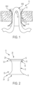
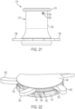
- FIGS. 1, 2 and 9 illustrate an exemplary embodiment of a stomal device 10 in accordance with the subject disclosure.
- the stomal device 10 includes an elongated hollow body 12, a first flange or flap 14 extending from the hollow body, a second flange or flap 16 extending from the hollow body, and a pin 18 for extending through the second flange.
- the elongated hollow body 12 is generally configured as best shown in FIGS. 1, 2 , and 6 .
- the hollow body includes a first open end 22 about its first end 24 and a second open end 26 about its second end 28 opposite the first end.
- the first and second open ends are in fluid communication.
- the hollow body 12 is substantially tubular.
- the hollow body can be configured to have a curved cone shape including substantially curved cone shaped ends or portions 30, 32.
- the hollow body is structured to have an average overall height of about 5.0 to 6.0 cm, including 4.9, 5.1, 5.2, 5.3, 5.4, 5.5, 5.6, 5.7, 5.8, 5.9, 6.1 and 6.2 cm, thereby accommodating patients of varies sizes e.g., in a thin patient the height of the hollow body can be smaller and for an obese patient the height of the hollow body can be larger.
- the hollow body is also structured to have an inner diameter or aperture opening size from about 2.5 to 3.0 cm, including 2.4, 2.6, 2.7, 2.8, 2.9, and 3.1 cm or more e.g., to accommodate larger patients where a larger inner diameter may be required. Further, about its mid-section, the hollow body is structured to have an overall inner diameter of about 2.4-2.6 cm, which is smaller than the overall diameter of the hollow body about its respective ends.
- the hollow body can be flexible and formed from a resilient, pliable material.
- the hollow body can be formed from a medical grade polymer e.g., silicone, polytetrafluoroethylene (PTFE), perfluoroalkoxy alkanes (PFA), THV (a polymer of tetrafluoroethylene, hexafluoropropylene and vinylidene fluoride), polyamide (PA), ethylene vinyl acetate (EVA), cyclic olefin copolymers (COCS), flexible polyvinyl chloride (PVC), flexible polyurethane, or other inert and non-reactive materials.
- a medical grade polymer e.g., silicone, polytetrafluoroethylene (PTFE), perfluoroalkoxy alkanes (PFA), THV (a polymer of tetrafluoroethylene, hexafluoropropylene and vinylidene fluoride), polyamide (PA), ethylene vinyl acetate
- the hollow body can be formed of suitable rigid materials, such as metal, a rigid polymer, e.g., polyethylene (PE), polyether ether ketone (PEEK), polyvinylidene difluoride (PVDF), rigid polyvinyl chloride (PVC), rigid polyurethane, or a composite.
- a rigid polymer e.g., polyethylene (PE), polyether ether ketone (PEEK), polyvinylidene difluoride (PVDF), rigid polyvinyl chloride (PVC), rigid polyurethane, or a composite.
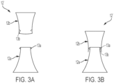
- the hollow body can be configured as a modular hollow body 12', as shown in FIGS. 3A and 3B .
- the modular hollow body 12' includes a first hollow body portion 12a and a second hollow body portion 12b that is connectable or attachable to the first hollow body portion.
- the modular hollow body is segmented about its mid-portion. That is, the first and second hollow body portions are connected together about the modular hollow body's mid-portion e.g., via a fastener, such as a detent or cooperating detents 13a, 13b on the first and second hollow body portions.
- a fastener such as a detent or cooperating detents 13a, 13b on the first and second hollow body portions.
- the first flange 14 or inner flap is a radially extending flange that extends from a first end of the hollow body 12.
- the first flange 14 can be a tapered flange and have a tubular or curved cone shaped inner side and a tapered outer side such that it gradually extends outwardly from the first end forming a substantially curved cone shaped end, or it can alternatively be configured as a substantially planar flange extending radially outwardly.
- the second flange 16 or outer flap is a radially extending flange that extends from a second end of the hollow body 12.
- the second flange 16 can be a tapered flange and have a tubular or curved cone shaped inner side and a tapered outer edge such that it gradually extends outwardly from the second end forming a substantially curved cone shaped end, or it can alternatively be configured as a substantially planar flange extending radially outwardly.
- the first flange 14 of the hollow body 12 has an overall diameter greater than the second flange 16.
- the first flange can have an overall diameter of from about 6.5 to 7.5 cm, including 6.4, 6.6, 6.7, 6.8, 6.9, 7.0, 7.1, 7.2, 7.3, 7.4, and 7.6 cm
- the second flange can have an overall diameter of from about 5.0 to 6.0 cm, including 4.9, 5.1, 5.2, 5.3, 5.4, 5.5, 5.6, 5.7, 5.9 and 6.1 cm.
- the first flange is preferably larger in diameter than the second flange such that, when the hollow body is inserted into the incision, the stomal device is self-retaining in the incision and resists dislodgement from the body cavity.
- the opposed through holes 36 can be formed in the hollow body of the stomal device.
- the opposed through holes 36 extend through the side wall of the hollow body such that its longitudinal axis traverses a longitudinal direction of the hollow body.
- the opposed through holes are preferably positioned about a medial region of the hollow body.
- the opposed through holes can alternatively be configured to pass through the second flange.
- a longitudinal axis of the pin traverses the longitudinal direction of the hollow body.
- the stomal device is configured such that a central longitudinal axis of the pin is substantially perpendicular to a central longitudinal axis of the hollow body.
- the pin is structured to pass through the opposed through holes 36 ( FIG. 2 ) in or adjacent the second flange 16 for releasably retaining a portion of an internal organ, e.g., an extracted loop of the bowel 1000 ( FIG. 1 ), exteriorly of the surgical incision. That is, the pin 18 is inserted beneath the bowel loop 1000 to prevent the bowel loop from sinking back into the abdomen of a patient. The pin 18 controls retraction and withdrawal of the bowel during treatment of a patient. When access to the bowel is no longer needed, the pin 18 can be removed to allow the bowel loop to sink back into the abdomen.
- an internal organ e.g., an extracted loop of the bowel 1000 ( FIG. 1 )
- the pin 18 is configured as a rod having a substantially cylindrical rod shape with an overall length of about 6 to 8 cm and an overall diameter of about 4 to 6 mm.
- the pin preferably has a length greater than an overall diameter of the second flange 16 to facilitate removal of the pin from the second flange.
- the pin's overall diameter is preferably constant throughout its entire length.
- the pin 18 can also include a stop 38 ( FIG. 8 ), such as a radial rib for preventing the pin from falling out of or pass the opposing through holes.
- the pin is formed from a rigid material suitable for sterilization, such as a metal or rigid polymer.
- FIGS. 4 , 6 and 7 illustrate another exemplary embodiment of a stomal device 410 in accordance with the subject disclosure.
- the stomal device 410 is similar to stomal device 10 and includes an elongated hollow body 412, a first flange 414, a second flange 416, and a pin 418.
- the stomal device 410 additionally comprises a wafer 420 positionable adjacent the second flange 416.
- the wafer 420 may be of an annular flange or other radially projecting rim, collar, disc or rib configuration.
- a central opening 440 of the wafer is in fluid communication with and sized to substantially match a second open end of the hollow body 412.
- the overall diameter of the wafer is sized to substantially match that of the second flange.
- the wafer 420 also includes an upwardly extending annular rib 442 spaced from its outer circumferential edge to facilitate connection to an optional pouch 444, further described below.
- the annular rib sits proud of an upper surface of the wafer.
- the wafer 420 can be formed from substantially rigid reinforced or unreinforced medical grade polymer, cardboard, metal, or other suitable materials.
- the wafer 420 is a barrier applied to the skin adjacent the hollow body 412.
- the wafer 420 is configured to separate a portion of a body organ, e.g., the bowel, from a surgical incision 1002 ( FIG. 1 ).
- the wafer advantageously separates the incision (and skin) from the bowel so as to prevent or retard formation of scar tissue around the stoma. Otherwise, if scar tissue is permitted to form, surgery may be required to detach the bowel from the abdominal wall (or skin).
- the wafer 420 may be applied to the skin using a bio-compatible adhesive or other suitable fastener.
- the stomal device of the subject disclosure including the first and second flanges can be configured to have an overall height of about 5.0 to 6.0 cm, including 4.9, 5.1, 5.2, 5.3, 5.4, 5.5, 5.6, 5.7, 5.8, 5.9, and 6.1 cm, although in a thin patient the height of the hollow body can be smaller and for an obese patient the height of the hollow body can be larger, and an overall height or thickness of the wafer of about 1.0 to 4.0 mm, including 0.9, 1.2, 1.4, 1.6, 1.8, 2.0, 2.2, 2.4, 2.6, 2.8, 3.2, 3.4, 3.6, 3.8 and 4.1 mm.
- the overall diameter of the stomal device can range from 5.0 to 7.5 cm, including 4.8, 5.2, 5.4, 5.6, 5.8, 6.0, 6.2, 6.4, 6.6, 6.8, 7.0, 7.2, 7.4 and 7.6 cm, and preferably tapers inwardly about its mid-section to an outer diameter of about 2.9 to 3.3 cm, including 2.7, 2.8, 3.0, 3.1, 3.2 and 3.4 cm.
- the stomal device 410 can optionally include a pouch 444 to enable removal and disposal of fluid and/or waste material from the patient.
- the pouch includes an opening 446 attachable to the annular rib of the wafer such that the opening is in fluid communication with the second open end of the hollow body 412.
- the pouch 444 can alternatively be removably attached to the wafer 420 by suitable mechanical fasteners 447 such as threading, detents, hook and loop type fasteners, releasable adhesives, and the like.
- a medical provider e.g ., a surgeon places the stomal device 10 at a pre-determined stoma site ( FIG. 1 ) for a loop stoma at the time of the initial loop ileostomy/colostomy surgery.
- a circular skin incision is made at the pre-determined stoma site.
- the incision is deepened, and the muscles split or separated rather than cut, after which the stomal device is inserted, either intact or in modular fashion, into the incision.
- the stomal device is inserted, leading with the first flange, into the incision.
- the hollow body 12 is configured for insertion into a surgical incision provided, e.g., in the abdominal wall.
- the first flange 14 is configured for releasably retaining the body in the surgical incision when the hollow body is inserted into the surgical incision
- the second flange 16 is configured for resting atop a patient's skin when the hollow body is inserted into the surgical incision.
- the first flange 14 extends radially from the hollow body about the interior of the abdominal wall and the second flange 16 extends radially from the midportion about the exterior of the abdominal wall, i.e., atop a patient's skin.
- the user folds or compresses the stomal device so as to allow it to pass through the incision site.
- the first flange 14 is released from the confines of the incision and unfolds radially outwardly from the incision.
- the second flange 16 comes to rest on the patient's skin. Referring to FIG.
- implantation of the stomal device allows for a loop of a bowel (large or small) to be brought out of the abdomen through the hollow body 12.
- the pin 18 can then be placed beneath the bowel loop to support the bowel loop exteriorly of the abdomen for easy access by the medical provider.
- sutures 500 are used to connect the open edges of the bowel loop 1004 to the second flange 416 to keep the stoma in the bowel loop open. That is, the user sutures with non-absorbable suture the open edges of the bowel loop to the second flange of the stomal device.
- the user subsequently applies the wafer 420 to the skin around the incision site ( FIG. 4 ). Specifically, the central opening 440 of the wafer 420 is slid over the bowel loop whereupon the wafer is then placed against the patient's skin (and optionally secured thereto by a suitable bio-compatible adhesive).
- the wafer 420 prevents or inhibits the formation of scar tissue around the stoma as it separates the abdominal wall (and skin) from the bowel. This provides a significant benefit as if scar tissue were permitted to form, surgery may be required to detach the bowel from the abdominal wall (or skin). If the user elects to use the pouch, then the user can removably connect the pouch 444 to the wafer periodically to enable removal and disposal of any fluid and/or waste material from the patient.
- the pin 418 is withdrawn from the through holes in or adjacent to the second flange 416 and the bowel loop retracts into the abdomen of the patient.
- the wafer 420 is then removed to expose the plurality of sutures 500.
- the plurality of sutures is then removed and the stomal device 410 is withdrawn from the incision. Thereafter, sutures can be placed to close the bowel loop opening.
- the device ensures ease of use and allows for a rapid surgical procedure to reverse a loop stoma in the operating room, or even in an office or clinic setting.
- the stomal device can be installed either intact, or alternatively, in a modular fashion to minimize the size of an incision at the stoma site. Such a rapid surgical procedure can eliminate the need for a post-operative hospitalization to recover from said procedure.
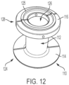
- FIGS. 10-12 illustrate another exemplary embodiment of a stomal device 110 in accordance with the subject disclosure.
- This stomal device 110 operates and includes features substantially as disclosed for stomal device 10, except as specifically discussed hereinafter.
- the stomal device 110 is generally configured as best shown in FIGS. 10-12 and includes an elongated hollow body 112, a first flange 114 and a second flange 116.
- the stomal device 110 can be formed of a flexible and/or pliable material such as those discussed for the above embodiments including silicone, or other inert and non-reactive materials. In the present embodiment shown in FIGS.
- the entire stomal device 110 is formed from the same material e.g., silicone, polytetrafluoroethylene (PTFE), perfluoroalkoxy alkanes (PFA), THV (a polymer of tetrafluoroethylene, hexafluoropropylene and vinylidene fluoride), polyamide (PA), ethylene vinyl acetate (EVA), cyclic olefin copolymers (COCS), flexible polyvinyl chloride (PVC), or flexible polyurethane.
- the stomal device 110 is formed as a unitary construct.
- the stomal device 110 can be formed as separate components later secured together e.g., via welding or an adhesive.
- the elongated hollow body 112 includes a first open end 122 about its first end 124 and a second open end 126 about its second end 128 opposite the first end.
- the first and second open ends are in fluid communication.
- the hollow body 112 is substantially tubular or tubular, and may have constant overall and inner diameter throughout its entire longitudinal length.
- the hollow body may have a height substantially the same as the height of the hollow body 12 of the stomal device 10 described above.
- the aperture size opening or inner diameter of the hollow body may range from about 2.5 to 3.0 cm, including 2.4, 2.6, 2.7, 2.8, 2.9, and 3.1 cm, although for an obese patient the inner diameter can be large than 3.1 cm
- the first flange or inner flap 114 is a radially extending flange that extends from the first end 124 of the hollow body 112. As illustrated, the first flange 114 is configured as a thin annular ring extending radially from the first end of the hollow body.
- the first flange can have a thickness that ranges from about 1.0 mm to 2.0 mm, including 0.9, 1.1, 1.2, 1.3, 1.4, 1.5, 1.6, 1.7, 1.8, 1.9, and 2.1 mm.
- the outer diameter of the first flange may range from about 6.5 cm to 7.5 cm, including 6.4, 6.6, 6.7, 6.8, 6.9, 7.0, 7.1, 7.2, 7.3, 7.4, and 7.6 cm.
- the second flange or outer flap 116 is a radially extending flange that extends from the second end 128 of the hollow body 112.
- the second flange 16 can be configured as a substantially planar flange extending radially outwardly.
- the second flange is configured to be thicker than the first flange so as to accommodate through holes 136 for receiving an unillustrated pin, similar to pin 18 described above, which is used to support a portion of a bowel.
- the thickness of the second flange may range from about 0.8 cm to 1.2 cm, including 0.7, 0.9, 1.0, 1.1, and 1.3 cm.
- the outer diameter of the second flange may range from about 5.0 to 6.0 cm, including 4.9, 5.1, 5.2, 5.3, 5.4, 5.5, 5.6, 5.7, 5.8, 5.9, and 6.1 cm.
- the second flange can also include a substantially circular rib 125 ( FIG. 12 ) extending from its outer or upper side for facilitating connection to an unillustrated wafer similar to wafer 20, described above.
- the circular rib 125 is spaced from an outer circumference of the second flange and/or spaced from an inner surface of the annular second flange. So constructed, the second flange has an overall diameter that is less than an overall diameter of the first flange.
- the stomal device can alternatively be configured as a modular stomal device 110'. That is, the stomal device can be comprised of at least two portions e.g., a first portion 110a and a second portion 110b. The two body portions 110a and 110b can have varying tubular body heights to enable a user to select the appropriate overall height of the hollow body portion to closely accommodate a particular patient's abdominal wall thickness.
- the stomal device also includes fasteners 113 for releasably securing the first and second portions together.
- the fasteners can include cooperating detents 113a, 113b or an adhesive, and the like suitable for its intended use.
- the stomal device 110' can include a plurality of fasteners 115 extending along a longitudinal length of the hollow body portions to allow for variable adjustment of the overall height of the hollow body by a user. All other aspects of the stomal device 110' are similar to that described above for stomal device 110.
- this stomal device 110' when pressure is applied to the body 112' or when the body 112' of the stomal device is squeezed, the two portions of the body 112' are separable due to the detents 113a, 113b moving apart from each other. When pressure to the body 112' is released, the two portions of the body 112' can be secured together due to the cooperating connection structure, e.g., via the detents 113a, 113b coming into interlocking engagement as shown in FIG. 13B .
- the modular construction of the stomal device 110' advantageously accommodates patients and stoma sites of varying abdominal wall thicknesses and allows for small incision sites. Moreover, the modular nature of the stomal device facilitates easy step-wise removal of the device when a stoma is no longer needed.
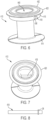
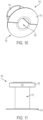
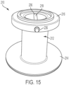
- FIGS. 14-17 illustrate another exemplary embodiment of a stomal device 210 in accordance with the subject disclosure.
- the stomal device 210 includes a hollow body 212, a first flange 214, a second flange 216, and a pin 218.
- This embodiment of the stomal device 210 operates and includes features substantially as disclosed for the above embodiments, except as specifically discussed hereinafter.
- the hollow body 212 of the stomal device 210 can be constructed and dimensioned similar to the hollow body 112 of the stomal device 110 described above.
- the second flange 216 of the stomal device 210 can be constructed and dimensioned similar to the second flange 116 of the stomal device 110 (see FIG. 17 ).
- the first flange 214 of the stomal device 210 is constructed as best shown in FIGS. 14-16 .
- the first flange 214 is structured in a Belleville washer-like manner having a tapered bottom surface.
- the tapered bottom surface facilitates insertion of the stomal device into the incision.
- the top surface of the first flange 214 is configured as a planar surface.
- the first flange can have a maximum thickness that ranges from about 2.0 to 3.0 mm, and a minimum thickness from about 1.0 mm to 2.0 mm about its peripheral end.
- the outer diameter of the first flange may range from about 6.5 cm to 7.5 cm, including 6.4, 6.6, 6.7, 6.8, 6.9, 7.0, 7.1, 7.2, 7.3, 7.4, and 7.6 cm.
- the stomal device 210 can be formed from a flexible, pliable and resilient material including, for example, silicone, polytetrafluoroethylene (PTFE), perfluoroalkoxy alkanes (PFA), THV (a polymer of tetrafluoroethylene, hexafluoropropylene and vinylidene fluoride), polyamide (PA), ethylene vinyl acetate (EVA), cyclic olefin copolymers (COCS), flexible polyvinyl chloride (PVC), flexible polyurethane, or other inert and non-reactive materials.
- the stomal device 210 can be formed from a suitable rigid material, e.g., a metal, a rigid polymer, or a composite.
- the stomal device In operation, due to the flexible material used to form the stomal device 210 e.g., silicone, the stomal device can be collapsed or folded to facilitate implantation of into the incision in the abdominal cavity. After insertion, pressure to the body 212 is released to allow the stomal device to return to its original uncollapsed shape.
- the flexible material used to form the stomal device 210 e.g., silicone
- the stomal device can be collapsed or folded to facilitate implantation of into the incision in the abdominal cavity. After insertion, pressure to the body 212 is released to allow the stomal device to return to its original uncollapsed shape.
- the open edges of the stoma are sutured with non-absorbable stitches to the second flange 216 (similar to the suturing of the open edges of the stoma described above in connection with FIG. 9 ) to secure the stomal device in place.
- the stomal device 210 After gaining access to the abdominal cavity, the stomal device 210 allows for a loop of a bowel (large or small) to be brought out of the abdomen through a central cavity or through the hollow body 212.
- the pin 218 is constructed as or similar in construction to that of pin 18 and 418 discussed above. Similar to the pins discussed above, the pin 218 allows for the user a means to support a bowel therein during treatment of a patient. When access to the bowel is no longer needed, the pin 218 can be withdrawn through the through holes 236 of the second flange 216 to remove the pin and allow the bowel to retract back into the abdomen.
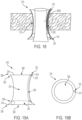
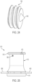
- FIGS. 18, 19A, 19B , 20A and 20B illustrate another exemplary embodiment of a stomal device 310 in accordance with the subject disclosure.
- the stomal device 310 includes a hollow body 312 having a first flange 314, a second flange 316, and a balloon 370.
- This embodiment of the stomal device 310 operates and includes features substantially as disclosed for the above embodiments, except as specifically discussed hereinafter.
- the stomal device 310 advantageously allows for the closure of an end stoma while also being operable to provide transient/intermittent continence during a temporary end colostomy or end ileostomy surgical procedure.
- the hollow body 312, including the first flange and the second flange, can be of a unitary construction formed from a flexible material, such as but not limited to silicone, polytetrafluoroethylene (PTFE), perfluoroalkoxy alkanes (PFA), THV (a polymer of tetrafluoroethylene, hexafluoropropylene and vinylidene fluoride), polyamide (PA), ethylene vinyl acetate (EVA), cyclic olefin copolymers (COCS), flexible polyvinyl chloride (PVC), flexible polyurethane, or other inert and non-reactive materials.
- a flexible material such as but not limited to silicone, polytetrafluoroethylene (PTFE), perfluoroalkoxy alkanes (PFA), THV (a polymer of tetrafluoroethylene, hexafluoropropylene and vinylidene fluoride), polyamide (PA), ethylene vinyl acetate (EV
- the hollow body can be formed from a suitable rigid material, e.g., a metal, a rigid polymer, or a composite.
- the hollow body 312 allows the user to draw out an end portion of a bowel (e.g., colon or small intestine) from the abdomen that will form an opening or stoma ( FIG. 18 ).
- the elongated hollow body 312 is generally configured as best shown in FIG. 19 .
- the hollow body includes a first open end 322 about its first end 324 and a second open end 326 about its second end 328 opposite the first end.
- the first and second open ends are in fluid communication.
- the hollow body 312 is substantially tubular.
- the hollow body can also be configured to have a curved cone shape including substantially curved cone shaped ends or portions 330, 332.
- the hollow body is structured to have an overall height of about 5.0 to 6.0 cm, including 4.9, 5.1, 5.2, 5.3, 5.4, 5.5, 5.6, 5.7, 5.8, 5.9, and 6.1 cm, although in a thin patient the height of the hollow body can be smaller and for an obese patient the height of the hollow body can be larger.
- the hollow body is also structured to have an overall outer diameter from about 2.9 to 3.3 cm, including 2.7, 2.8, 3.0, 3.1, 3.2 and 3.4 cm.
- the hollow body is structured to have an inner diameter or aperture opening size from about 2.5 to 3.0 cm, including 2.6, 2.7, 2.8 and 2.9 cm, although for an obese patient the inner diameter can be larger.
- the mid-section is smaller than the overall diameter of the hollow body about its respective ends.
- the first flange or inner flap 314 is a radially extending flange that extends from the first end 324 of the hollow body 312.
- the first flange 314 can be a tapered flange having a tapered outer side such that it gradually extends outwardly from the first end forming a substantially curved cone shaped end, or it can alternatively be configured as a substantially planar flange extending radially outwardly.
- the second flange or outer flap 316 is a radially extending flange that extends from the second end 328 of the hollow body 312.
- the second flange 316 can be a tapered flange such that it gradually extends outwardly from the second end forming a substantially curved cone shaped end, or it can alternatively be configured as a substantially planar flange extending radially outwardly.
- the first flange 314 of the hollow body 312 has an overall diameter greater than the second flange 316. Again, the relatively larger diameter of the first flange serves to resist dislodgement of the hollow body from an incision.
- the balloon 370 is preferably secured to and extends from the first flange 314 of the stomal device. More particularly, the balloon extends from an inner surface of the hollow body adjacent the first flange.
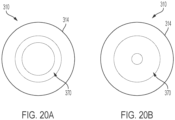
- the balloon 370 can be an annular-shaped balloon having an inner through hole configured to move between a first overall diameter and a second overall diameter smaller than the first overall diameter.
- the balloon 370 is also formed from an elastic material that allows the balloon to increase its volume when inflated from an initial volume of 1X ( FIG. 20A ) to an expanded volume ( FIG. 20B ) of 2X, 3X, 4X, 5X or more of the initial volume. In doing so, the overall diameter of the through hole decreases when going from the initial volume to the expanded volume.
- the balloon when inflated can change its inner through hole diameter from e.g., about 2.5 cm to about 5 mm.
- the balloon also includes an elongated nozzle 372 extending therefrom for use in inflating and deflating the balloon.
- the nozzle 372 includes an inlet 374 that is position adjacent a top end of the second flange.
- the nozzle also includes a valve 375 for inflating or deflating the balloon.
- the valve may be adapted to accept a syringe (not shown) for injecting or withdrawing air or another gas into the balloon.
- the hollow body 312 includes a channel 376 within which the nozzle extends through and the valve resides.
- the channel has a length sized sufficiently to extend from about the first flange to the second flange as shown in FIG. 19A . That is, channel extends along a longitudinal extent of the hollow body 312.
- the stomal device 310 can also include a wafer similar to wafer 420 discussed above for use in preventing or retarding formation of scar tissue around the end stoma.
- the stomal device 310 may be implanted at a pre-determined stoma site in a similar fashion as described above for the stomal device 10.
- the user draws an identified end portion of a bowel from the abdomen through the hollow body of the stomal device.
- the user then inserts a syringe into the nozzle 372 of the second flange and injects air or another appropriate gas so as to inflate the balloon 370 adjacent the first flange.
- the balloon 370 compresses an end portion of the bowel passing through the hollow body to provide temporary continence to the end stoma.
- the stomal device 310 is operable to provide temporary continence while allowing the patient avoid wearing a stoma pouch bag while the balloon is inflated, as may otherwise be required in traditional temporary end colostomy or end ileostomy surgical procedures. If the user desires to allow the end stoma to evacuate fluid and/or waste material, the user may withdraw air through the nozzle 372 via e.g., a syringe, so as to deflate the balloon ( FIG. 20A ).
- the stomal device 510 includes a hollow body 512, a first flange 514 and a second flange 516.
- the hollow body has a two-part construction.
- the first part includes a substantially cylindrical outer body member 550 having an upper end terminating beneath the second flange and an annular gear 552 at its lower end.
- the annular gear 554 includes gear teeth circumscribing its circumference and is sized to have an overall diameter less than an overall diameter of the outer body member distal end or lower most end.
- the annular gear 554 has its outer circumference spaced from the outer circumference of the lower most end of the outer body.
- the second part includes a substantially cylindrical inner body member 556 having an upper end connected to and extending downwardly from the second flange 516 and a lower end connected to the first flange 514.
- the first flange 514 is a substantially annular flange having a plurality of receptacles for receiving respective arms, as further discussed below.
- one of the inner body member and the outer body member is movable relative to the other. For example, the inner body member may rotate relative to the outer body member.
- the upper portion of the inner and outer body is substantially tubular and the second flange is a substantially planar flange extending from the inner body member.
- the lower portion of the inner and outer body is substantially curved coned shaped, having an overall diameter larger at its most distal end than the overall diameter of the upper portion of the inner and outer body.
- the hollow body including the first and second flange, can be formed from a suitable rigid material, e.g., a metal, a rigid polymer, or a composite.
- a suitable rigid material e.g., a metal, a rigid polymer, or a composite.
- the overall height and width dimensions of the stomal device 510 are the same or substantially the same as the dimensions of the stomal devices discussed above.
- the stomal device 510 further comprises a plurality of radially extendable and retractable arms 558 (which are shown in their extended position in FIGS. 21 and 22 ).
- the stomal device includes six extendable arms, but can include more or less e.g., 2, 3, 4, 5, 7, and 8.
- Each arm 558 is connected to a spur gear 560 that is rotatably supported in the first flange 514.
- the gears 560 meshingly engage with the annular gear 552 of the outer body member to pivot each arm respectively between a retracted position and an extended position.
- each arm pivots such that its distal end travels an arc length of about 80 - 100 degrees including 75, 85, 90, 95 and 105 degrees between the extended and retracted positions.
- the stomal device comprises a fastener or locking mechanism to secure the outer body member in a fixed position relative to the inner body member.
- the locking mechanism can be a set screw 562 ( FIGS. 21 , 23 and 24 ) that is threadedly engaged with outer body member 550.
- the outer end of the set screw includes a socket 564 for receiving an unillustrated tool for turning the set screw, and the inner end of the set screw includes a tapered tip 566 for contacting the inner body member 556.
- the locking mechanism can a detent between the inner and outer body members or a threaded engagement between the inner and outer body members.
- the second flange 516 is grasped by one of the user's hands and the outer body member 550 is grasped by the other of the user's hands.
- the user then rotates the outer body member in a first direction relative to the second flange to retract the arms 558 into the first flange 514 or into the retracted position.
- the stomal device is configured for implantation into an incision.
- the stomal device 510 is implanted similar to stomal devices 10 and 410 described above.
- the first flange 514 is inserted into the incision until it passes beneath the inner surface of the abdominal wall and the second flange 516 comes to rest on the patient's skin.
- the user rotates the outer body member in a second direction relative to the second flange to extend the arms 558 radially outwardly of the first flange 514 whereby they assume the position shown in FIGS. 21 and 22 .
- the user then tightens the set screw 562 until it comes into firm engagement with the inner body member 556, thereby locking the arms into a radially extended position.
- the radially extended arms 558 operate to resist inadvertent dislodgement of the stomal device 510 from the incision.
- the hollow body 512 allows the user to draw out a loop of a bowel from the abdomen that will form an opening or stoma.
- An unillustrated pin similar to pin 18 or 418 described above is inserted through unillustrated opposed through holes provided in the second flange 516 and beneath the bowel loop to support the bowel loop exteriorly of the patient's body.
- a wafer similar to wafer 420 described above is then placed around the stoma and atop the second flange and a pouch similar to pouch 444 may be connected to the wafer in the manner described above.
- the pouch and wafer are removed and the stoma is sutured shut.
- the pin is then withdrawn whereupon the bowel loop retracts into the abdomen.
- the set screw 562 is then loosened and the outer body member is turned in a direction to retract the arms 558 into the first flange 514.
- the stomal device is then withdrawn from the incision and the incision is sutured shut.
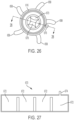
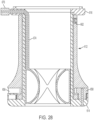
- FIGS. 25 , 26 and 28 illustrate another exemplary embodiment of a stomal device 610 in accordance with the subject disclosure.
- the stomal device 610 includes a hollow body 612 having a first flange 614, a second flange 616, and a balloon 670.
- This embodiment of the stomal device 610 operates and includes features substantially as disclosed for the embodiment of the stomal device 510 described above in connection with FIGS. 21-23 , except as specifically discussed hereinafter.
- the stomal device 610 advantageously allows for the closure of an end stoma while also being operable to provide transient/intermittent continence during a temporary end colostomy or end ileostomy surgical procedure.
- the hollow body 612 is structured to have an inner diameter or aperture opening size from about 2.5 to 3.0 cm, including 2.4, 2.6, 2.7, 2.8, 2.9, and 3.1 cm (although for an obese patient the inner diameter can be larger) which is smaller than the overall diameter of the hollow body about its respective ends.
- stomal device 610 includes a locking mechanism e.g., a set screw 662 which releasably locks inner and outer body members of the hollow body 612 in a fixed position relative to each other e.g., between first and second positions where arms 658 are either in their radially extended position, as shown in FIG. 25 , or in an retracted position ( FIG. 28 ) where the arms are positioned within a circumference defined by the outer edges of the first flange.
- a locking mechanism e.g., a set screw 662 which releasably locks inner and outer body members of the hollow body 612 in a fixed position relative to each other e.g., between first and second positions where
- the balloon 670 is carried on an interior wall of the inner body member of the hollow body ( FIGS. 26 and 28 ). As shown in FIG. 27 , the balloon includes a plurality of inflatable pockets 672 in fluid communication with one another and a gas, e.g., air fill tube 674, which is in fluid communication with an inflation/deflation valve 676 ( FIGS. 25 , 26 and 28 ) positioned within or about the second flange 616.
- the valve 676 can be constructed similar to an athletic ball inflation/deflation valve.
- the valve may be formed of flexible material, e.g., silicone, and have a self-sealing orifice that can be penetrated by a syringe tip which enables the balloon to be easily inflated and deflated.
- the balloon 670 is also formed from an elastic material that allows the balloon to increase its volume when inflated from an initial volume of 1X to an expanded volume ( FIGS. 26 and 28 ) of 2X, 3X, 4X, 5X or more of the initial volume. In doing so, the overall diameter of a bowel-receiving through hole 678 defined by the balloon decreases when going from the initial volume to the expanded volume.
- the balloon when inflated can change its inner through hole diameter from e.g., about 2.5 cm to about 5 mm.
- the stomal device 610 can also include a wafer similar to wafer 420 discussed above for use in preventing or retarding formation of scar tissue around the end stoma.
- the stomal device 610 may be implanted at a pre-determined stoma site and arms 658 are brought into their radially extended positions in a similar fashion as described above for the stomal device 510.
- the user draws an identified end portion of a bowel from the abdomen through the hollow body of the stomal device.
- the user then inserts a syringe into the valve 676 and injects air or another appropriate gas so as to inflate the balloon 670.
- the balloon 670 compresses an end portion of the bowel passing through the hollow body to provide temporary continence to the end stoma.
- the stomal device 610 is operable to provide temporary continence while allowing the patient to avoid wearing a stoma pouch bag while the balloon is inflated, as may otherwise be required in traditional temporary end colostomy or end ileostomy surgical procedures. If the user desires to allow the end stoma to evacuate fluid and/or waste material, the user may withdraw air through the valve 676 via e.g., a syringe, so as to deflate the balloon.
- the subject disclosure describes stomal devices for facilitating a stoma or reversal of a stoma.
- the stomal device can include a unitary or a modularly constructed stomal device.
- the stomal device can be installed either as a single construct, or alternatively, in a modular fashion to minimize the size of an incision at the stoma site.
- the multi-segmented (i.e., modular) construction of the stomal devices advantageously accommodates patients and stoma sites of varying abdominal wall thicknesses. Moreover, the modular nature of the stomal devices facilitates step-wise removal of the device when a stoma is no longer needed. Accordingly, the stomal devices of the subject disclosure reduces the need for an invasive surgical procedure, for example, in an operating room or similar setting, to reverse or close the stoma. Instead, the user may perform closure of the stoma in an office or clinic setting, thereby reducing recovery time such as hospitalization for several days. It is contemplated that fascial stitches and bowel purse string sutures may be utilized for closure after removal of the stomal device.
- the subject disclosure also describes a method for implanting a stomal device and for facilitating reversal of a stoma.
- the implantation method includes, forming an incision site to receive a stomal device, inserting the stomal device of the subject disclosure through the incision site, withdrawing a portion of a bowel through the stomal device, inserting a pin below a loop of a bowel and through the stomal device to prevent the bowel loop from retracting back into the abdomen of a patient.
- the method can include the steps of withdrawing the pin from the flange or hollow body of the stomal device, retracting the bowel loop back into the abdomen of the patient, and withdrawing the stomal device from the patient.
Claims (15)
- Dispositif de stomie (10, 110, 110', 210, 310, 410, 510, 610) caractérisé par :un corps creux allongé (12, 12', 112, 112', 212, 312, 512, 612) ayant une première extrémité ouverte (22) autour de sa première extrémité (24) et une seconde extrémité ouverte (26) en communication fluidique avec la première extrémité ouverte autour de sa seconde extrémité (28) à l'opposé de la première extrémité ;une première bride (14, 114, 214, 314, 414, 514, 614) s'étendant à partir de la première extrémité du corps creux ;une seconde bride (16, 116, 216, 316, 416, 516, 616) s'étendant à partir de la seconde extrémité du corps creux ; etune broche (18, 218, 418) destinée à s'étendre à travers la seconde bride transversale à une direction longitudinale du corps creux.
- Dispositif de stomie selon la revendication 1, dans lequel le corps creux est sensiblement tubulaire, ou est en forme de cône courbe, ou comporte une paire de parties en forme de cône incurvé.
- Dispositif de stomie selon la revendication 1 ou la revendication 2, dans lequel le corps creux est modulaire ou dans lequel le corps creux comprend une première partie de corps (12a) pouvant être raccordée à une seconde partie de corps (12b).
- Dispositif de stomie selon l'une quelconque des revendications 1, ou 2 ou 3, dans lequel la première bride est une bride effilée comportant un côté intérieur tubulaire et un côté extérieur effilé.
- Dispositif de stomie selon l'une quelconque des revendications 1, 2, 3 ou 4, dans lequel la seconde bride comprend une nervure sensiblement circulaire (125) s'étendant depuis son côté extérieur.
- Dispositif de stomie selon l'une quelconque des revendications 1, 2, 3, 4 ou 5, comprenant en outre une plaquette (420) adjacente à la seconde bride ou une plaquette adjacente à la seconde bride, dans lequel la plaquette comporte une ouverture centrale (440) en communication fluidique avec la seconde extrémité ouverte.
- Dispositif de stomie selon l'une quelconque des revendications 1, 2, 3, 4, 5 ou 6, comprenant en outre une poche (444) qui comporte une ouverture (446) pouvant être fixée à la seconde bride de telle sorte que l'ouverture est en communication fluidique avec la seconde extrémité ouverte.
- Dispositif de stomie selon l'une quelconque des revendications 1, 2, 3, 4, 5, 6 ou 7, dans lequel le corps creux est flexible, ou est formé à partir de silicone, de polytétrafluoroéthylène (PTFE), d'alcanes de perfluoroalcoxy (PFA), de THV (un polymère de tétrafluoroéthylène, d'hexafluoropropylène et de fluorure de vinylidène), de polyamide (PA), d'éthylène-acétate de vinyle (EVA), de copolymères d'oléfine cyclique (COCS), de chlorure de polyvinyle flexible (PVC) ou de polyuréthane flexible.
- Dispositif de stomie selon l'une quelconque des revendications 1, 2, 3, 4, 5, 6, 7 ou 8, dans lequel la première bride a un diamètre global supérieur à la seconde bride.
- Dispositif de stomie selon l'une quelconque des revendications 1, 2, 3, 4, 5, 6, 7, 8 ou 9, dans lequel la seconde bride comporte des trous traversants opposés (36, 136, 236) pour recevoir la broche à l'intérieur de celle-ci, ou dans lequel la broche a une longueur supérieure à un diamètre global de la seconde bride.
- Dispositif de stomie selon la revendication 1, comprenant en outre un ballonnet (370, 670) s'étendant depuis la première bride, ou une buse (372) raccordée de manière fonctionnelle au ballonnet ayant une entrée (374) adjacente à la seconde bride.
- Dispositif de stomie selon la revendication 1, comprenant en outre un ballonnet (370, 670) porté par un intérieur du corps creux, ou une pluralité de bras extensibles radialement (558) adjacents à la première bride.
- Dispositif de stomie selon la revendication 1, dans lequel le corps creux comprend un élément de corps interne (556) et un élément de corps externe (550), et dans lequel l'un de l'élément de corps interne et de l'élément de corps externe est mobile par rapport à l'autre.
- Dispositif de stomie selon la revendication 13, dans lequel l'élément de corps externe comporte une extrémité inférieure ayant un engrenage annulaire (552), une pluralité de bras extensibles (558) ayant chacun un engrenage droit (560) mis en prise avec l'engrenage annulaire, et un mécanisme de verrouillage (562) pour fixer l'élément de corps externe dans une position fixe par rapport à l'élément de corps interne.
- Dispositif de stomie selon la revendication 14, comprenant en outre une pluralité de bras extensibles ayant chacun un engrenage droit (560) mis en prise avec l'engrenage annulaire, ou comprenant en outre un mécanisme de verrouillage (562) pour fixer l'élément de corps externe dans une position fixe par rapport à l'élément de corps interne.
Applications Claiming Priority (2)
| Application Number | Priority Date | Filing Date | Title |
|---|---|---|---|
| US202063039507P | 2020-06-16 | 2020-06-16 | |
| PCT/US2021/037672 WO2021257732A1 (fr) | 2020-06-16 | 2021-06-16 | Dispositif de stomie |
Publications (2)
| Publication Number | Publication Date |
|---|---|
| EP4153103A1 EP4153103A1 (fr) | 2023-03-29 |
| EP4153103B1 true EP4153103B1 (fr) | 2024-03-06 |
Family
ID=76859765
Family Applications (1)
| Application Number | Title | Priority Date | Filing Date |
|---|---|---|---|
| EP21740341.9A Active EP4153103B1 (fr) | 2020-06-16 | 2021-06-16 | Dispositif de stomie |
Country Status (4)
| Country | Link |
|---|---|
| US (1) | US20230233356A1 (fr) |
| EP (1) | EP4153103B1 (fr) |
| CA (1) | CA3183072A1 (fr) |
| WO (1) | WO2021257732A1 (fr) |
Family Cites Families (3)
| Publication number | Priority date | Publication date | Assignee | Title |
|---|---|---|---|---|
| US6716209B2 (en) * | 2002-02-22 | 2004-04-06 | Arnold Robert Leiboff | Loop ostomy device and methods for its use |
| GB2487929B (en) * | 2011-02-08 | 2016-04-06 | Europ Inst Of Surgical Res And Innovation Ltd | Port for Laparoscopic Surgery with a Flexible Membrane |
| US20200038229A1 (en) * | 2018-08-06 | 2020-02-06 | Covidien Lp | Stomal support device |
-
2021
- 2021-06-16 US US18/001,790 patent/US20230233356A1/en active Pending
- 2021-06-16 CA CA3183072A patent/CA3183072A1/fr active Pending
- 2021-06-16 EP EP21740341.9A patent/EP4153103B1/fr active Active
- 2021-06-16 WO PCT/US2021/037672 patent/WO2021257732A1/fr unknown
Also Published As
| Publication number | Publication date |
|---|---|
| US20230233356A1 (en) | 2023-07-27 |
| CA3183072A1 (fr) | 2021-12-23 |
| WO2021257732A1 (fr) | 2021-12-23 |
| EP4153103A1 (fr) | 2023-03-29 |
Similar Documents
| Publication | Publication Date | Title |
|---|---|---|
| US11395757B2 (en) | Continent ostomy valve and method of use | |
| AU2006293719B2 (en) | Abdominal reinforcement device | |
| JP5625055B2 (ja) | 人工肛門造設術 | |
| EP1574189B1 (fr) | Ruban réglable chirurgical implantable avec profil plat lors de l'implantation | |
| JP4202432B2 (ja) | 皮膚用インプラントデバイス | |
| EP2033604B1 (fr) | Ensemble ballonnet intragastrique | |
| EP1607071B1 (fr) | Procédé d'assemblage d'un ruban réglable | |
| JP2005312966A (ja) | カテーテル接続管が中心部に配置されている外科的に移植可能な注入ポート | |
| US20050183730A1 (en) | Method for implanting an adjustable band | |
| US20040006311A1 (en) | Drain catheters | |
| EP1607072B1 (fr) | Un ruban réglable à fluide amélioré | |
| AU2005203525A1 (en) | An improved fluid adjustable band | |
| EP2600809B1 (fr) | Ensemble pour stomie | |
| EP1628583A1 (fr) | Tube de calibrage de gastroplastie a pointe flexible et a gonflage asymetrique | |
| EP4153103B1 (fr) | Dispositif de stomie | |
| WO2020250145A1 (fr) | Prothèse pour patients porteurs d'entérostomie | |
| US20230218424A1 (en) | Endoluminal stoma device | |
| WO2023069735A1 (fr) | Dispositif de stomie endoluminale | |
| AU2005202672A1 (en) | Improvement in Adjustable Gastric Band | |
| AU2004243673A1 (en) | Asymmetrically inflating flexi-tip gastroplasty calibration tube |
Legal Events
| Date | Code | Title | Description |
|---|---|---|---|
| STAA | Information on the status of an ep patent application or granted ep patent |
Free format text: STATUS: UNKNOWN |
|
| STAA | Information on the status of an ep patent application or granted ep patent |
Free format text: STATUS: THE INTERNATIONAL PUBLICATION HAS BEEN MADE |
|
| PUAI | Public reference made under article 153(3) epc to a published international application that has entered the european phase |
Free format text: ORIGINAL CODE: 0009012 |
|
| STAA | Information on the status of an ep patent application or granted ep patent |
Free format text: STATUS: REQUEST FOR EXAMINATION WAS MADE |
|
| 17P | Request for examination filed |
Effective date: 20221221 |
|
| AK | Designated contracting states |
Kind code of ref document: A1 Designated state(s): AL AT BE BG CH CY CZ DE DK EE ES FI FR GB GR HR HU IE IS IT LI LT LU LV MC MK MT NL NO PL PT RO RS SE SI SK SM TR |
|
| P01 | Opt-out of the competence of the unified patent court (upc) registered |
Effective date: 20230602 |
|
| DAV | Request for validation of the european patent (deleted) | ||
| DAX | Request for extension of the european patent (deleted) | ||
| GRAP | Despatch of communication of intention to grant a patent |
Free format text: ORIGINAL CODE: EPIDOSNIGR1 |
|
| STAA | Information on the status of an ep patent application or granted ep patent |
Free format text: STATUS: GRANT OF PATENT IS INTENDED |
|
| INTG | Intention to grant announced |
Effective date: 20231020 |
|
| GRAS | Grant fee paid |
Free format text: ORIGINAL CODE: EPIDOSNIGR3 |
|
| GRAA | (expected) grant |
Free format text: ORIGINAL CODE: 0009210 |
|
| STAA | Information on the status of an ep patent application or granted ep patent |
Free format text: STATUS: THE PATENT HAS BEEN GRANTED |
|
| AK | Designated contracting states |
Kind code of ref document: B1 Designated state(s): AL AT BE BG CH CY CZ DE DK EE ES FI FR GB GR HR HU IE IS IT LI LT LU LV MC MK MT NL NO PL PT RO RS SE SI SK SM TR |
|
| REG | Reference to a national code |
Ref country code: CH Ref legal event code: EP |
|
| REG | Reference to a national code |
Ref country code: IE Ref legal event code: FG4D |
|
| REG | Reference to a national code |
Ref country code: DE Ref legal event code: R096 Ref document number: 602021010184 Country of ref document: DE |