EP4152905B1 - Tauchgekühlte elektronische vorrichtung und kühlungsüberwachungssystem für tauchgekühlte elektronische vorrichtung - Google Patents
Tauchgekühlte elektronische vorrichtung und kühlungsüberwachungssystem für tauchgekühlte elektronische vorrichtung Download PDFInfo
- Publication number
- EP4152905B1 EP4152905B1 EP22306240.7A EP22306240A EP4152905B1 EP 4152905 B1 EP4152905 B1 EP 4152905B1 EP 22306240 A EP22306240 A EP 22306240A EP 4152905 B1 EP4152905 B1 EP 4152905B1
- Authority
- EP
- European Patent Office
- Prior art keywords
- electronic device
- heat
- cooling
- liquid
- controller
- Prior art date
- Legal status (The legal status is an assumption and is not a legal conclusion. Google has not performed a legal analysis and makes no representation as to the accuracy of the status listed.)
- Active
Links
Images


Classifications
-
- G—PHYSICS
- G06—COMPUTING OR CALCULATING; COUNTING
- G06F—ELECTRIC DIGITAL DATA PROCESSING
- G06F1/00—Details not covered by groups G06F3/00 - G06F13/00 and G06F21/00
- G06F1/16—Constructional details or arrangements
- G06F1/20—Cooling means
-
- G—PHYSICS
- G01—MEASURING; TESTING
- G01M—TESTING STATIC OR DYNAMIC BALANCE OF MACHINES OR STRUCTURES; TESTING OF STRUCTURES OR APPARATUS, NOT OTHERWISE PROVIDED FOR
- G01M3/00—Investigating fluid-tightness of structures
- G01M3/02—Investigating fluid-tightness of structures by using fluid or vacuum
- G01M3/04—Investigating fluid-tightness of structures by using fluid or vacuum by detecting the presence of fluid at the leakage point
- G01M3/16—Investigating fluid-tightness of structures by using fluid or vacuum by detecting the presence of fluid at the leakage point using electric detection means
-
- G—PHYSICS
- G01—MEASURING; TESTING
- G01M—TESTING STATIC OR DYNAMIC BALANCE OF MACHINES OR STRUCTURES; TESTING OF STRUCTURES OR APPARATUS, NOT OTHERWISE PROVIDED FOR
- G01M3/00—Investigating fluid-tightness of structures
- G01M3/02—Investigating fluid-tightness of structures by using fluid or vacuum
- G01M3/04—Investigating fluid-tightness of structures by using fluid or vacuum by detecting the presence of fluid at the leakage point
-
- G—PHYSICS
- G01—MEASURING; TESTING
- G01M—TESTING STATIC OR DYNAMIC BALANCE OF MACHINES OR STRUCTURES; TESTING OF STRUCTURES OR APPARATUS, NOT OTHERWISE PROVIDED FOR
- G01M3/00—Investigating fluid-tightness of structures
- G01M3/02—Investigating fluid-tightness of structures by using fluid or vacuum
- G01M3/26—Investigating fluid-tightness of structures by using fluid or vacuum by measuring rate of loss or gain of fluid, e.g. by pressure-responsive devices, by flow detectors
- G01M3/32—Investigating fluid-tightness of structures by using fluid or vacuum by measuring rate of loss or gain of fluid, e.g. by pressure-responsive devices, by flow detectors for containers, e.g. radiators
- G01M3/3236—Investigating fluid-tightness of structures by using fluid or vacuum by measuring rate of loss or gain of fluid, e.g. by pressure-responsive devices, by flow detectors for containers, e.g. radiators by monitoring the interior space of the containers
- G01M3/3245—Investigating fluid-tightness of structures by using fluid or vacuum by measuring rate of loss or gain of fluid, e.g. by pressure-responsive devices, by flow detectors for containers, e.g. radiators by monitoring the interior space of the containers using a level monitoring device
-
- H—ELECTRICITY
- H02—GENERATION; CONVERSION OR DISTRIBUTION OF ELECTRIC POWER
- H02H—EMERGENCY PROTECTIVE CIRCUIT ARRANGEMENTS
- H02H5/00—Emergency protective circuit arrangements for automatic disconnection directly responsive to an undesired change from normal non-electric working conditions with or without subsequent reconnection
- H02H5/08—Emergency protective circuit arrangements for automatic disconnection directly responsive to an undesired change from normal non-electric working conditions with or without subsequent reconnection responsive to abnormal fluid pressure, liquid level or liquid displacement, e.g. Buchholz relays
- H02H5/083—Emergency protective circuit arrangements for automatic disconnection directly responsive to an undesired change from normal non-electric working conditions with or without subsequent reconnection responsive to abnormal fluid pressure, liquid level or liquid displacement, e.g. Buchholz relays responsive to the entry or leakage of a liquid into an electrical appliance
-
- H—ELECTRICITY
- H02—GENERATION; CONVERSION OR DISTRIBUTION OF ELECTRIC POWER
- H02H—EMERGENCY PROTECTIVE CIRCUIT ARRANGEMENTS
- H02H5/00—Emergency protective circuit arrangements for automatic disconnection directly responsive to an undesired change from normal non-electric working conditions with or without subsequent reconnection
- H02H5/08—Emergency protective circuit arrangements for automatic disconnection directly responsive to an undesired change from normal non-electric working conditions with or without subsequent reconnection responsive to abnormal fluid pressure, liquid level or liquid displacement, e.g. Buchholz relays
- H02H5/086—Emergency protective circuit arrangements for automatic disconnection directly responsive to an undesired change from normal non-electric working conditions with or without subsequent reconnection responsive to abnormal fluid pressure, liquid level or liquid displacement, e.g. Buchholz relays of cooling or lubricating fluids
-
- H—ELECTRICITY
- H05—ELECTRIC TECHNIQUES NOT OTHERWISE PROVIDED FOR
- H05K—PRINTED CIRCUITS; CASINGS OR CONSTRUCTIONAL DETAILS OF ELECTRIC APPARATUS; MANUFACTURE OF ASSEMBLAGES OF ELECTRICAL COMPONENTS
- H05K7/00—Constructional details common to different types of electric apparatus
- H05K7/20—Modifications to facilitate cooling, ventilating, or heating
- H05K7/20709—Modifications to facilitate cooling, ventilating, or heating for server racks or cabinets; for data centers, e.g. 19-inch computer racks
- H05K7/20763—Liquid cooling without phase change
- H05K7/20781—Liquid cooling without phase change within cabinets for removing heat from server blades
-
- G—PHYSICS
- G08—SIGNALLING
- G08B—SIGNALLING OR CALLING SYSTEMS; ORDER TELEGRAPHS; ALARM SYSTEMS
- G08B21/00—Alarms responsive to a single specified undesired or abnormal condition and not otherwise provided for
- G08B21/18—Status alarms
- G08B21/182—Level alarms, e.g. alarms responsive to variables exceeding a threshold
-
- H—ELECTRICITY
- H05—ELECTRIC TECHNIQUES NOT OTHERWISE PROVIDED FOR
- H05K—PRINTED CIRCUITS; CASINGS OR CONSTRUCTIONAL DETAILS OF ELECTRIC APPARATUS; MANUFACTURE OF ASSEMBLAGES OF ELECTRICAL COMPONENTS
- H05K7/00—Constructional details common to different types of electric apparatus
- H05K7/20—Modifications to facilitate cooling, ventilating, or heating
- H05K7/20218—Modifications to facilitate cooling, ventilating, or heating using a liquid coolant without phase change in electronic enclosures
- H05K7/20236—Modifications to facilitate cooling, ventilating, or heating using a liquid coolant without phase change in electronic enclosures by immersion
-
- H—ELECTRICITY
- H05—ELECTRIC TECHNIQUES NOT OTHERWISE PROVIDED FOR
- H05K—PRINTED CIRCUITS; CASINGS OR CONSTRUCTIONAL DETAILS OF ELECTRIC APPARATUS; MANUFACTURE OF ASSEMBLAGES OF ELECTRICAL COMPONENTS
- H05K7/00—Constructional details common to different types of electric apparatus
- H05K7/20—Modifications to facilitate cooling, ventilating, or heating
- H05K7/20218—Modifications to facilitate cooling, ventilating, or heating using a liquid coolant without phase change in electronic enclosures
- H05K7/20272—Accessories for moving fluid, for expanding fluid, for connecting fluid conduits, for distributing fluid, for removing gas or for preventing leakage, e.g. pumps, tanks or manifolds
Definitions
- the present technology relates to immersion-cooled electronic equipment.
- the present technology relates to detection of anomalies in cooling of an immersion-cooled electronic device.
- Electronic equipment for example servers, memory banks, computer disks, and the like, is conventionally grouped in equipment racks.
- Large data centers and other large computing facilities may contain thousands of racks supporting thousands or even tens of thousands of servers.
- the racks including equipment mounted in their backplanes, consume large amounts of electric power and generate significant amounts of heat. Cooling needs are important in such racks.
- Liquid cooling in particular water cooling
- Cold plates for example water blocks having internal channels for channelized water circulation
- heat-generating components such as processors
- Immersion cooling (sometimes called immersive cooling) has also recently gained traction.
- Electronic components are inserted in a container that is fully or partially filled with a non-conducting cooling liquid, for example an oil-based dielectric cooling liquid. Efficient thermal contact is obtained between the electronic components and the dielectric cooling liquid.
- Immersion cooling systems commonly take the form of large tanks in which the electronic devices are submerged. Hybrid cooling systems involving both water cooling and immersion cooling have recently been introduced.
- cooling systems may not be efficient enough to remove enough thermal energy from the electronic device and/or may be prone to malfunctions (e.g. leakage of water within the dielectric cooling liquid).
- a system for monitoring the cooling systems of an immersion-cooled electronic device may be desirable.
- U.S. Patent Application Publication No. 2013/0146273 discloses a sealable module adapted to be filled with a first cooling liquid and a heat transfer device having a conduction surface defining a channel for receiving a second cooling liquid. At least a portion of the conduction surface or housing is shaped in conformity with the shape of the electronic component.
- Implementations of the present technology each have at least one of the above-mentioned object and/or aspects, but do not necessarily have all of them. It should be understood that some aspects of the present technology that have resulted from attempting to attain the above-mentioned object may not satisfy this object and/or may satisfy other objects not specifically recited herein.
- FIG. 1 shows a perspective view of a rack system 100 for housing numerous rack-mounted assemblies 104.
- the rack system 100 may include a rack frame 102, rack-mounted assemblies 104, a liquid cooling inlet conduit 106 and a liquid cooling outlet conduit 108.
- the rack-mounted assemblies 104 may be oriented vertically with respect to the rack frame 102, resembling books on a library shelf. This arrangement may provide for mounting a large number of such rack-mounted assemblies 104 in the rack frame 102, relative to conventional arrangements, particularly with respect to conventional arrangements of immersion-cooled rack-mounted assemblies.
- Figure 2 shows another perspective view of the rack system 100.
- the rack system 100 may further comprise a power distribution unit 110 and liquid coolant inlet/outlet connectors 114.
- the rack system 100 may include other components such as heat exchangers, cables, pumps or the like, however, such components have been omitted from Figures 1 and 2 for clarity of understanding.
- the rack frame 102 may include shelves 103 to accommodate one or more rack-mounted assemblies 104.
- the one or more rack-mounted assemblies 104 may be arranged vertically with respect to the shelves 103.
- guide members (not shown) may be used on the shelves 103 to guide the rack-mounted assemblies 104 into position during racking and de-racking, and to provide proper spacing between the rack-mounted assemblies 104 for racking and de-racking.
- FIG. 3 is a schematic diagram of electronic connections of the electronic devices 120 (e.g. servers) hosted in the rack system 100.
- each electronic device 120 is electrically connected to a power distribution unit (PDU) 110 in parallel with one or more other electronic devices 120.
- PDU power distribution unit
- a plurality of PDUs 110 may be used to distribute electric power to all of the electronic devices 120 hosted in the rack system 100.
- three PDUs 110 receive electric power from a same or different power supplies and distribute electric power to a plurality of corresponding electronic devices 120.
- each electronic device 120 is electrically connected to a corresponding PDU 110 over a switching device 310 (e.g. a Solid State Relay).
- the switching device 310 is selectively closed or open to respectively disconnect and connect the electronic device 120 to the PDU 110. Operation of the switching device 310 is performed by a controller 500 (see Figure 5 ) and is described in greater details herein after.
- Each PDU 110 includes an input connector for receiving electric power from a power supply (e.g. AC power supply).
- the power supply may be a monophasic power supply or a multi-phasic power supply.
- the input connector may be, for example and without limitation, a CEE 7-type plug for use in European countries.
- Each PDU 110 further includes a plurality of output connectors for electrically connecting a plurality of corresponding electronic devices 120 via the switching devices 310.
- the output connectors may be, for example and without limitations, C13-type plugs.
- each PDU 110 includes eight (8) output connectors.
- Figure 4 shows a perspective view of the rack-mounted assembly 104.
- the rack-mounted assembly 104 includes a detachable frame, or "board" 118 of the electronic device 120, and an immersion case 116.
- the board 118 holds electronic components 122 of the electronic device 120 and may be immersed in the immersion case 116.
- the immersion case 116, board 118, and electronic components 122 are show as separate parts, it will be understood by one of ordinary skill in the art that, in some embodiments, two or more of these components could be combined.
- the electronic components 122 could be fixed directly on the board 118 and/or the immersion case 116.
- the rack system 100 may use a cooling system to cool down the electronic devices 120 to prevent the electronic devices 120 from being damaged.
- the cooling system is a hybrid cooling system including an immersion cooling system and a channelized cooling system.
- an immersion cooling system is a cooling system in which the electronic device is in direct contact with a non-conductive (dielectric) cooling liquid, which either flows over at least portions of the electronic device, or in which at least portions of the electronic device are submerged.
- the immersion case 116 may contain a dielectric immersion cooling liquid (not shown in Figure 4 ).
- the board 118 including the electronic components 122 may be submerged at least in part in the immersion cooling case 116.
- the dielectric immersion cooling liquid and the board 118 may be inserted into the immersion case 116 via an opening 122 at the top of the immersion case 116.
- the opening 122 may remain at least partially open during operation of the electronic device 120, providing a non-sealed configuration for the immersion case 116.
- Such non-sealed configurations may be easier to manufacture and maintain than sealed configurations, but may be inappropriate for, e.g., two-phase systems, in which the immersion cooling liquid may boil during operation of the electronic device 120.
- the immersion case 116 may also include structures or devices for cooling the dielectric cooling liquid.
- a convection-inducing structure such as a serpentine convection coil 124 in which a flow of cooling liquid (e.g. water) is maintained may be used to cool the dielectric cooling liquid via natural convection.
- a pump (not shown) may be used to circulate the dielectric cooling liquid either within the immersion case 116 or through an external cooling system (not shown).
- a two-phase system in which dielectric cooling liquid in a gaseous phase is cooled by condensation may be used.
- any technology or combination for cooling the dielectric cooling liquid may be used without departing from the principles disclosed herein.
- the serpentine convection coil 124 may be omitted or replaced with other convection-inducing structures or devices for circulating the dielectric immersion cooling liquid in some embodiments.
- a channelized cooling system is a cooling system in which heat-generating components of the electronic device 120 (i.e. the electronic components 122) are cooled using one or more liquid cooling units 250, which may also be called “cold plates” or “water blocks” (although a liquid circulating through the “water blocks” may be any of a wide variety of known thermal transfer liquids, rather than water). Liquid connections of the liquid cooling units 250 are described in greater details herein after.
- thermal transfer devices examples include, but are not limited to, central processing units (CPUs), graphics processing units (GPUs), neural processing units (NPUs), tensor processing units (TPUs), power supply circuitry, and application specific integrated circuits (ASICs), including, for example, ASICs configured for high-speed cryptocurrency mining.
- CPUs central processing units
- GPUs graphics processing units
- NPUs neural processing units
- TPUs tensor processing units
- ASICs application specific integrated circuits
- the present disclosure describes a cooling monitoring system that detect anomalies of the cooling of the electronic device 120 and that may disconnect the electronic device 120 from its corresponding power supply in reponse to detecting an anomaly.
- FIG. 5 is a schematic representation of a cooling monitoring system 400 implemented in the rack-mounted assembly 104 in accordance with some embodiments of the present technology.
- the electronic device 120 is a server that may be implemented as a conventional computer server.
- each electronic device 120 may be implemented as a Dell TM PowerEdge TM Server running the Microsoft TM Windows Server TM operating system.
- each electronic device 120 may be implemented in any other suitable hardware, software, and/or firmware, or a combination thereof.
- the electronic device 120 includes one or more electronic components 122 (only one of which is illustrated for clarity of the Figure 5 ) and the board 118 on which the one or more electronic components 122 are mounted.
- the board 118 is at least in part immersed in the immersion case 116 that contains a volume of a heat-transfer liquid 315 for cooling of the electronic device 120. More specifically, the electronic device 120 is at least in part immersed in the heat-transfer liquid 315 for immersion cooling thereof.
- the heat-transfer liquid 315 is a dielectric cooling liquid.
- the electronic device 120 may be referred to as a "immersion-cooled electronic device".
- the electronic device 120 is also cooled by the channelized cooling system that circulates a channelized cooling liquid, or a "second heat-transfer liquid", through one or more liquid cooling units 250 (only one of which is illustrated for clarity of the Figure 5 ) such as "water blocks" on the electronic component 122 or some other heat-generating components of the electronic device.
- the liquid cooling unit 250 has an external thermal transfer surface configured to be in contact with the electronic component 122.
- the external thermal transfer surface is said to be "in contact" with the electronic component 122 even in cases where a thermal paste is applied between the external thermal transfer surface and the electronic component 122, in a manner that is known in the art, to ensure adequate heat transfer between the electronic component 122 and the external thermal transfer surface of the liquid cooling unit 250.
- the liquid cooling unit 250 is thermally coupled to the electronic component 122 to be cooled, and the channelized cooling liquid is circulated through an internal liquid conduit (not shown) of the liquid cooling unit 250 to absorb the heat from the electronic device 120. As the heat-transfer liquid flows out of the liquid cooling unit 250, so does the thermal energy absorbed thereby.
- the liquid cooling unit 250 may for example include a liquid inlet 252 fluidly connected to the liquid cooling inlet conduit 106 of the rack 100 ( Figure 1 ) for receiving the second heat-transfer liquid.
- the second heat-transfer liquid may thus flow through the internal liquid conduit of the liquid cooling unit 250 that zigzags within the liquid cooling unit 250 to maximize the heat absorption potential of the heat-transfer liquid across a surface of the liquid cooling unit 250.
- the internal liquid conduit may terminate at a liquid outlet 254 for discharging hot second heat-transfer liquid to the liquid cooling outlet conduit 108 of the rack 100 ( Figure 1 ).
- the second heat-transfer liquid is further directed in a channelized cooling loop 260 to be cooled in a heat exchanger (e.g. a dry cooler).
- a heat exchanger e.g. a dry cooler
- the liquid cooling unit 250 is also submerged within the heat-transfer liquid 315.
- the serpentine convection coil 124 introduced in the description of Figure 4 may be structured with multiple hollow-channel coils to provide a high surface area exposure relative to the heat-transfer liquid 315 while also maintaining compact overall length and width dimensions. With this structure, direct channelized liquid cooling within the serpentine convection coil 124 allows to cool the ambient temperature of the heat-transfer liquid 315 and to induce natural thermal convection in the heat-transfer liquid 315. That is, the serpentine convection coil 124 internally conveys the circulating channelized cooling liquid that operates to cool the heat-transfer liquid 315.
- the channelized cooling liquid may be a different liquid than the heat-transfer liquid 315.
- the channelized cooling liquid may include water, alcohol, or any suitable liquid capable of sustaining adequate cooling temperatures.
- the channelized cooling liquid comprisees water and glycol.
- the serpentine convection coil 124 is connected in series with the liquid cooling unit 250, the latter being in a downstream position.
- the liquid cooling unit 250 may be upstream of the serpentine convection coil 124.
- the channelized cooling liquid may flow in parallel within the liquid cooling unit 250 and the serpentine convection coil 124.
- the liquid cooling unit 250 and the serpentine convection coil 124 may be independent, being connected to different sources of cooling liquid.
- multiple electronic devices similar to the electronic device 120, may be immersed in a single immersion case or an immersion tank.
- the cooling monitoring system 400 includes the controller 500 and one or more sensors communicably connected to the controller 500.
- the sensors transmit measurement signals for the operating parameter of the heat-transfer liquid 315 to the controller 500.
- the controller 500 further determines that the measurement signals indicate that the operating parameter of the heat-transfer liquid 315 is above the threshold by comparing measurement values carried in the measurement signals with the threshold.
- the sensors transmit a fault signal to the controller 500 in response to detecting that the operating parameter of the heat-transfer liquid 315 is above the threshold.
- the controller 500 further cause to disconnect the electronic device 120 from the power supply in response to receiving the fault signal.
- the sensors may thus be refered to as "anomaly sensors”.
- Operating parameters that are measured by the sensors may be a temperature, a conductivity, a viscosity, a density, and/or any other physical or chemical characteristics of the heat-transfer liquid 315.
- the controller 500 is mounted on the board 118 of the electronic device 120 and operably connected to the corresponding switching device 310 of the electronic device 120 such that, in use, the controller 500 may open or close the switching device 310. More specifically, the controller 500 causes to disconnect, in response to determining that the measurement signals received from the sensors indicate that the operating parameter of the heat-transfer liquid 315 is above a given threshold, the electronic device 120 (i.e. the electronic components 122) from the power supply. As such, the cooling monitoring system 400 may increase safety of the rack system 100 and, more generally, of the datacenter, by electrically and individually disconnecting servers or other electronic devices 120 from power supplies in response to detecting faulty cooling in corresponding rack-mounted assemblies 104.
- the switching device 310 may be integrated in the electronic device 120. In other embodiments, the switching device 310 may be located outside the electronic device 120 (e.g. along a power line that transmits electric power from the PDU 110 to the electronic device 120).
- hybrid cooling systems for electronic devices120 may include both immersion cooling systems, in which the electronic devices are immersed or submerged in a dielectric immersion cooling liquid, and channelized cooling systems, in which heat transfer devices such as water blocks are used to cool components of the electronic device, using a liquid that flows through channels between and within the heat transfer devices.
- the same liquid may be used as both the dielectric immersion cooling liquid and the channelized cooling liquid (i.e., the liquid that flows through the water blocks).
- the characteristics of the dielectric immersion cooling liquid and/or the cost of the dielectric immersion cooling liquid may render it inappropriate for use in the channelized cooling system.
- the channelized cooling liquid will be water, or some other liquid that provides appropriate heat transfer characteristics for the channelized cooling system, but may not be usable for immersion cooling, e.g., due to its conductivity or due to corrosion or other damage that it may cause to components of the electronic device.
- the concentration of ions in the water will cause the water to be sufficiently conductive to cause damage to electronic components. Even if the water is initially provided as distilled or deionized water, the concentration of ions will increase as the water is circulated through the channelized cooling system.
- Dielectric immersion cooling liquids are typically either hydrocarbon- or fluorocarbon-based and typically have densities that are lower than the density of water. If the channelized cooling liquid has a higher density than the dielectric immersion cooling liquid, which will typically be the case, then the channelized cooling fluid eventually leaking into the immersion cooling liquid will sink to a bottom portion of the immersion case.
- a leak detection arrangement such as a sensor, may be installed in a bottom portion of the immersion case 116 of each rack-mounted assembly 104 (or in a bottom portion of any part of the rack system 100 where the dielectric cooling liquid may flow) to detect the presence of the channelized cooling liquid, which would indicate that there is a leak in the channelized cooling system.
- this bottom portion of the immersion case 116 should be far enough below any immersed or submerged electronic device 120 that, absent a major leak, the channelized cooling fluid will not collect around any components of the electronic device 120.
- an alarm may be raised, or an operator may otherwise be informed of the immersion case 116 in which the leak was detected so that remedial measures may be taken.
- the sensors include a leak detection arrangement 600 communicably connected to the controller 500 and adapted to determine a presence of the second heat-transfer liquid in a bottom portion of the immersion case 116. More specifically, the second heat-transfer liquid used for liquid cooling of the electronic device 120 is selected to have a density that is higher than a density of the heat-transfer liquid 315. As a result, in case of leakage of the second heat-transfer liquid within the immersion case 116, the second heat-transfer liquid sinks to the bottom of the immersion case 116. In this embodiment, in order to detect a presence of the second heat-transfer liquid in the immersion case 116, the leak detection arrangement 600 is disposed in a bottom portion of the board 118. Broadly speaking, the leak detection arrangement 600 may include any sensor adapted to measure a temperature, a conductivity, a viscosity, a density, and/or any other physical or chemical characteristics of the heat-transfer liquid 315.
- the leak detection arrangement 600 includes one or more conductivity sensors 605 for determining a conductivity of a fluid at the bottom portion of the board 118.
- the second heat-transfer liquid is water.
- the conductivity sensors 605 are expected to determine a conductivity value that is non-null, or at least a variation of the measured conductivity value, in response to some of the second heat-transfer liquid having leaked to the bottom portion of the immersion case 116.
- the leak detection arrangement 600 transmits measurement signals including information about a measured conductivity of the heat-transfer liquid 315 to the controller 500.
- the controller 500 further determines that the measurement signals indicate that the conductivity of the heat-transfer liquid 315 is above the threshold by comparing measurement values carried in the measurement signals with the pre-determined conductivity threshold.
- the leak detection arrangement 600 transmits a fault signal to the controller 500 in response to determining that a real measured conductivity is above a predetermined conductivity threshold.
- value of the pre-determined conductivity threshold is stored in a memory of the controller 500 and the leak detection arrangement 600 transmits data including information about the real measured conductivity.
- the controller 500 then compares the real measured conductivity to the pre-determined conductivity threshold. In response to the real measured conductivity being greater than the pre-determined conductivity threshold, the controller 500 may open the switching device 310.
- the leak detection arrangement 600 includes a plurality of conductivity sensors 605 disposed one above another along a gravity axis, each conductivity sensor 605 being communicably connected to the controller 500.
- a fill rate of the second heat-transfer liquid in the immersive case 116 may be determined based on conductivity values measured by the conductivity sensors 605. More specifically, as the second heat-transfer liquid leaks from the channelized cooling loop 260, a bottommost conductivity sensor 605 may first transmit a fault signal to the controller 500.
- a second conductivity sensor 605, adjacent and above the bottommost conductivity sensor 605 along the gravity axis, may further transmit a second fault signal to the controller 500 upon measuring a conductivity value above the pre-determined conductivity threshold.
- a fill rate and temporal evolution thereof may thus be determined based on times of reception of the different fault signals from the respective conductivity sensors 605.
- the controller 500 further triggers, in response to determining the fill rate, a counter 502 indicative of an amount of time that has passed since the fill rate has been determined.
- the controller 500 may cause to disconnect the electronic device 120 from the power supply. More specifically, once the counter 502 reaches the first pre-determined count value, the controller 500 may open the switching device 310 to disconnect from the PDU 110 and from the power supply.
- the controller 500 in response to the counter 502 reaching a second pre-determined count value, may transmit an alert signal to an operator device communicably connected thereto to indicate occurence of an anomaly to an operator of the datacenter.
- the second pre-determined count value may be smaller than the first pre-determined count value. There may be a higher number of pre-determined count values and associated alert signals in alternative embodiments.
- the pre-determined count value is based on the determined fill rate. For example, the pre-determined count value associated with fill rate determined to be between 0.1L per hour and 0.4L per hour may be 30 minutes. The pre-determined count value associated with fill rate determined to be between 0.4L per hour and 0.8L per hour may be 10 minutes.
- the controller 500 may thus disconnect the electronic device 120 from the power supply before the leaking channelized cooling liquid reaches sensitive components of the electronic device 120 (e.g. the electronic components 122).
- the cooling monitoring system 400 further includes a temperature sensor 320.
- the temperature sensor 320 measures a temperature of the heat-transfer liquid 315, a vapor thereof and/or air located at a top portion of the immersion case 116.
- the temperature sensor 320 may be located near a top of the heat-transfer liquid 315, as shown on Figure 5 , or may be placed in any other suitable location.
- the temperature sensor 320 transmits a fault signal to the controller 500 in response to measuring a temperature above a pre-determined temperature threshold. As such, the controller 500 may open the switching device 310 to disconnect from the PDU 110 and from the power supply in response to the temperature at the top portion of the immersion case being greater than the pre-determined temperature threshold.
- the controller 500 may trigger a new parallel instance of the counter 502 upon receiving the fault signal from the temperature sensor 320.
- the controller 500 may cause to disconnect the electronic device 120 from the power supply. More specifically, once the counter 502 reaches the third pre-determined count value, the controller 500 may open the switching device 310 to disconnect the electronic device 120 from the PDU 110 and from the power supply.
- the controller 500 in response to the counter 502 reaching a fourth pre-determined count value, may transmit an alert signal to an operator device communicably connected thereto to indicate occurence of an anomaly to an operator of the datacenter.
- the fourth pre-determined count value may be smaller than the first pre-determined count value.
- a given rack system e.g. the rack system 100
- selective disconnection of the electronic devices 120 from the power supply by the corresponding controllers 500 facilitates operation of the electronic devices 120 in case an anomaly is detected. Indeed, if a faulty cooling system is detected by a corresponding cooling monitoring system 400, the corresponding electronic device 120 is disconnected from the power supply without impacting operation of the other electronic devices 120 in other rack-mounted assemblies 104 of the rack system 100.
- propagation of potential damages of a short-circuit occurring in a given electronic device 120 (e.g. server) of the datacenter is limited by individual discsonnection of the servers from the power supply.
- the controller 500 is communicably connected with an operator interface (not shown) of the datacenter (e.g. a control room of the datacenter) and transmits, in response to determining occurence of an anomaly, a second fault signal to the operator including information about the faulty electronic device 120 in which the cooling monitoring system 400 has detected an anomaly (e.g. leaking channelized cooling liquid).
- Said information may include, without limitation, an identification of the faulty electronic device 120 and data provided by the sensors.
- the controller 500 is communicably connected with a valve (e.g. a solenoid valve) located in the channelized cooling loop 260 upstream the serpentine convection coil 124 and the liquid cooling unit 250, external to the immersion case 116. In response to determining occurence of an anomaly, the controller 500 also closes the valve in order to limit damages to the electronic device 120.
- a valve e.g. a solenoid valve
- FIG. 6 shows an embodiment, in which the varying electrical properties of the liquids are used to detect a leak of the channelized cooling liquid.
- a bottom portion 804 of the immersion case 116 of a hybrid cooling system that includes both the aforementioned immersion cooling and channelized liquid cooling is shown.
- each conductivity sensor 605 of the leak detection arrangement 600 includes electrodes 820 and 822, which are used to measure the conductivity of the liquid between the electrodes 820 and 822. This may be done, e.g., by imposing a constant voltage between the electrodes 820 and 822, and measuring changes in the current that occur as a result of the conductivity/resistivity of the liquid. It will be understood that other known methods for measuring conductivity/resistivity could also be used.
- the dielectric immersion cooling liquid 315 has very low conductivity. Thus, when there has been no leak, there will be low conductivity (or high resistivity) between the electrodes 820 and 822. In the example shown in Figure 6 , a leak has occurred in the channelized cooling system, so channelized cooling liquid 808 is collected at the bottom of the immersion case 116. The conductivity of the channelized cooling liquid 808 is much higher than the conductivity of the dielectric immersion cooling liquid 806. When the level of the channelized cooling liquid 808 reaches the bottommost conductivity sensor 605, this difference in conductivity is detected by the electrodes 820 and 822, indicating that a leak has occurred.
- the electrodes 820 and 822 may be disposed within a single unit or holder of a given conductivity sensor 605 that is open to liquid, and that holds the electrodes 820 and 822 at a predetermined distance from each other.
- a holder may be configured to be mounted in the immersion case 116 through a "standardized" opening in the bottom portion of the immersion case 116, which is configured to receive any of a variety of sensors or other leak detection arrangements for determining the presence of the channelized cooling liquid in the bottom portion of the immersion case 116.
- the bottommost conductivity sensor 605 is immersed in the leaked channelized cooling liquid 808.
- a first conductivity measurement signal which may in this case be a fault signal, may thus be transmitted by the bottommost conductivity sensor 605 to the controller 500.
- a second conductivity measurement signal which may in this case be another fault signal, may be transmitted by said consecutive conductivity sensor 605 to the controller 500.
- a difference between reception times of the first and second signals may be used by the controller 500 to further determined the fill rate of the leaked channelized cooling liquid 808.
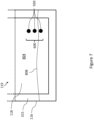
- FIG. 7 shows an embodiment in which a difference in pH is used to detect a leak.
- the leak detection arrangement 600 includes one or more pH sensors 920, which are used to measure the pH of the liquid in the immediate vicinity of the pH sensors 920. It will be understood that any known electrical, electrochemical, or electronic method for measuring pH could be used by the pH sensors 920.
- the dielectric immersion cooling liquid 315 and the channelized cooling liquid may have different pH values.
- the liquids may be selected to have this characteristic, or the pH may be measurably different simply due to chemical differences between the two liquids.
- a leak has occurred in the channelized cooling system, so the channelized cooling liquid 808 has collected at the bottom of the immersion case 116.
- the bottommost pH sensor 920 will detect that the liquid in the immediate vicinity of the pH sensor has a different pH than the dielectric immersion cooling liquid 315, indicating that a leak has occurred.
- the pH sensor may be configured to be mounted in the immersion case through a "standardized" opening in the bottom portion of the immersion case, which is configured to receive any of a variety of sensors or other leak detection arrangements for determining the presence of the channelized cooling liquid in the bottom portion of the immersion case.
- FIG. 8 is a schematic block diagram of the controller 500 of the cooling monitoring system 400 according to an embodiment of the present technology.
- the controller 500 comprises a processor or a plurality of cooperating processors (represented as a processor 510 for simplicity), a memory device or a plurality of memory devices (represented as a memory device 530 for simplicity), and an input/output interface 520 (or separate input and output interfaces) allowing the controller 500 to communicate with other components of the cooling monitoring system 400 and/or other components in remote communication with the cooling monitoring system 400.
- the processor 510 is operatively connected to the memory device 530 and to the input/output interface 520.
- the memory device 530 includes a storage for storing parameters 534, including for example and without limitation the above-mentioned predetermined conductivity thresholds.
- the memory device 530 may comprise a non-transitory computer-readable medium for storing code instructions 532 that are executable by the processor 510 to allow the controller 500 to perform the various tasks allocated to the controller 500.
- the controller 500 is operatively connected, via the input/output interface 520, to the leak detection arrangement 600, the switching device 310 and the temperature sensor 320.
- the controller 500 executes the code instructions 532 stored in the memory device 530 to implement the various above-described functions that may be present in a particular embodiment.
- Figure 6 as illustrated represents a non-limiting embodiment in which the controller 500 orchestrates operations of the cooling monitoring system 400. This particular embodiment is not meant to limit the present disclosure and is provided for illustration purposes.
- controller 500 may be part of electroinc device 120 and, more specifically, of the electronic components 122.
- the functions of the controller 500 described in the present disclosure may be performed by the electronic components 122 or any electronic component of the electronic device 120.
- the controller 500 is remotely connected (e.g. via a networking interface) to the switching device 310, the temperature sensor 320, the leak detection arrangement 600 and/or the electronic device 120.
- cooling monitoring system 400 its constituent components, and associated processes may be achieved by any one or more of hardware-based, software-based, and firmware-based elements. Such operational alternatives do not, in any way, limit the scope of the present disclosure.
- the cooling monitoring system 400 are part of the electronic device 120. More specifically, the electronic device 120 may include the sensors (i.e. the leak detection arrangement 600 and the temperature sensor 320) mounted on the board 118 of the electronic device 120 and communicably connected to the electronic device 120, the functions of the controller 500 being performed by the electronic device 120.
- the sensors i.e. the leak detection arrangement 600 and the temperature sensor 320 mounted on the board 118 of the electronic device 120 and communicably connected to the electronic device 120, the functions of the controller 500 being performed by the electronic device 120.
Landscapes
- Engineering & Computer Science (AREA)
- Physics & Mathematics (AREA)
- Microelectronics & Electronic Packaging (AREA)
- Thermal Sciences (AREA)
- General Physics & Mathematics (AREA)
- General Engineering & Computer Science (AREA)
- Computer Hardware Design (AREA)
- Fluid Mechanics (AREA)
- Theoretical Computer Science (AREA)
- Human Computer Interaction (AREA)
- Cooling Or The Like Of Electrical Apparatus (AREA)
- Cooling Or The Like Of Semiconductors Or Solid State Devices (AREA)
Claims (7)
- Elektronische Vorrichtung (120), die elektrische Energie von einer Stromversorgung empfängt, wobei die elektronische Vorrichtung (120) umfasst:eine Platine (118), die zumindest teilweise in ein Tauchgehäuse (116) eingetaucht ist, das eine erste Wärmeübertragungsflüssigkeit (315) zum Kühlen der elektronischen Vorrichtung (120) umfasst;wobei die elektronische Vorrichtung (120) durch ein oder mehrere elektronische Komponenten (122) gekennzeichnet ist, die auf der Platine (118) montiert und durch ein oder mehrere entsprechende Flüssigkeitskühleinheiten (250) in thermischem Kontakt damit gekühlt werden, wobei ein zweites Wärmeübertragungsfluid in der einen oder den mehreren Flüssigkeitskühleinheiten (250) kanalisiert wird, um die von den elektronischen Komponenten (122) erzeugte thermische Energie zu sammeln;wobei die elektronische Vorrichtung (120) ferner Folgendes umfasst:eine Leckdetektionsanordnung (600), die in einem unteren Abschnitt der Platine (118) angeordnet und konfiguriert ist, um ein Vorhandensein der zweiten Wärmeübertragungsflüssigkeit in einem unteren Abschnitt des Eintauchgehäuses (116) zu bestimmen, wobei die zweite Wärmeübertragungsflüssigkeit eine Dichte aufweist, die höher als eine Dichte der ersten Wärmeübertragungsflüssigkeit (315) ist; undeine Steuerung (500), die kommunikativ mit der Leckdetektionsanordnung (600) verbunden ist, wobei die Steuerung (500) konfiguriert ist, Signale von der Leckdetektionsanordnung (600) zu empfangen und als Reaktion auf das Bestimmen, dass die Signale das Vorhandensein der zweiten Wärmeübertragungsflüssigkeit im unteren Abschnitt des Tauchgehäuses (116) anzeigen, zu veranlassen, die elektronische Vorrichtung (120) von der Stromversorgung zu trennen.
- Elektronische Vorrichtung (120) nach Anspruch 1, wobei:die Leckdetektionsanordnung (600) dazu konfiguriert ist, ein Fehlersignal an die Steuerung (500) zu übertragen, als Reaktion auf das Detektieren des Vorhandenseins der zweiten Wärmeübertragungsflüssigkeit in dem unteren Abschnitt des Eintauchgehäuses (116); undwobei die Steuerung (500) dazu konfiguriert ist, zu veranlassen, dass die elektronische Vorrichtung (120) als Reaktion auf den Empfang des Fehlersignals von der Stromversorgung getrennt wird.
- Elektronische Vorrichtung (120) nach Anspruch 1, wobei:die Leckdetektionsanordnung (600) konfiguriert ist, Messsignale für den Betriebsparameter der ersten Wärmeübertragungsflüssigkeit (315) an die Steuerung (500) zu übertragen; undBestimmen, durch die Steuerung (500), dass die Signale das Vorhandensein der zweiten Wärmeübertragungsflüssigkeit im unteren Abschnitt des Tauchgehäuses (116) anzeigen, des Vergleichens von Messwerten, die in den Messsignalen getragen werden, mit einem Schwellenwert durch die Steuerung (500) umfasst.
- Elektronische Vorrichtung (120) nach einem der Ansprüche 1 bis 3, wobei:die zweite Wärmeübertragungsflüssigkeit Wasser umfasst;die Leckdetektionsanordnung (600) einen Leitfähigkeitssensor (605) umfasst; unddie Leckdetektionsanordnung (600) so konfiguriert ist, dass sie das Vorhandensein der zweiten Wärmeübertragungsflüssigkeit im unteren Abschnitt des Eintauchgehäuses (116) anzeigt, wenn die gemessene Leitfähigkeit eine vorbestimmte Leitfähigkeitsschwelle überschreitet.
- Elektronische Vorrichtung (120) nach Anspruch 4, wobei:der Leitfähigkeitssensor (605) eine Vielzahl von Leitfähigkeitssensoren (605) umfasst, die entlang einer Schwerkraftachse übereinander angeordnet sind; unddie Steuerung (500) dazu konfiguriert ist, die Füllrate der zweiten Wärmeübertragungsflüssigkeit innerhalb des Tauchgehäuses (116) basierend auf Fehlersignalen zu bestimmen, die von zwei oder mehr der Leitfähigkeitssensoren (605) übertragen werden.
- Elektronische Vorrichtung (120) nach Anspruch 5, wobei die Steuerung (500) ferner konfiguriert ist, um, ansprechend auf das Bestimmen der Füllrate:einen Zähler (502) auslösen, der anzeigt, wie viel Zeit seit dem Ermitteln der Füllrate vergangen ist; undin Reaktion darauf, dass der Zähler (502) einen ersten vorbestimmten Zählwert erreicht, Veranlassen des Trennens der elektronischen Vorrichtung von der Stromversorgung, wobei der erste vorbestimmte Zählwert auf der bestimmten Füllrate basiert.
- Elektronische Vorrichtung (120) nach einem der Ansprüche 1 bis 3, wobei:die zweite Wärmeübertragungsflüssigkeit einen pH-Wert aufweist, der sich von dem pH-Wert der ersten Wärmeübertragungsflüssigkeit (315) unterscheidet; undund die Leckdetektionsanordnung (600) einen pH-Sensor (920) umfasst.
Priority Applications (10)
| Application Number | Priority Date | Filing Date | Title |
|---|---|---|---|
| EP22306240.7A EP4152905B1 (de) | 2022-08-18 | 2022-08-18 | Tauchgekühlte elektronische vorrichtung und kühlungsüberwachungssystem für tauchgekühlte elektronische vorrichtung |
| EP22306276.1A EP4164355B1 (de) | 2022-08-18 | 2022-08-29 | Detektion und ablenkung von fluidleckagen in tauchkühlsystemen |
| US18/232,865 US20240064932A1 (en) | 2022-08-18 | 2023-08-11 | Immersion-cooled electronic device and cooling monitoring system for immersion-cooled electronic device |
| US18/233,922 US20240064933A1 (en) | 2022-08-18 | 2023-08-15 | Detection and deflection of fluid leakages in immersion cooling systems |
| CA3209729A CA3209729A1 (en) | 2022-08-18 | 2023-08-17 | Detection and deflection of fluid leakages in immersion cooling systems |
| CN202311040889.1A CN117589371A (zh) | 2022-08-18 | 2023-08-17 | 浸入式冷却系统中流体泄漏物的检测和偏转 |
| KR1020230107671A KR20240025479A (ko) | 2022-08-18 | 2023-08-17 | 침지-냉각 전자 장치 및 침지-냉각 전자 장치를 위한 냉각 모니터링 시스템 |
| KR1020230107690A KR20240025481A (ko) | 2022-08-18 | 2023-08-17 | 침지 냉각 시스템에서 유체 누출 감지 및 편향 |
| CA3209695A CA3209695A1 (en) | 2022-08-18 | 2023-08-17 | Immersion-cooled electronic device and cooling monitoring system for immersion-cooled electronic device |
| CN202311048498.4A CN117591361A (zh) | 2022-08-18 | 2023-08-18 | 浸入式冷却电子设备及冷却监测系统 |
Applications Claiming Priority (1)
| Application Number | Priority Date | Filing Date | Title |
|---|---|---|---|
| EP22306240.7A EP4152905B1 (de) | 2022-08-18 | 2022-08-18 | Tauchgekühlte elektronische vorrichtung und kühlungsüberwachungssystem für tauchgekühlte elektronische vorrichtung |
Publications (2)
| Publication Number | Publication Date |
|---|---|
| EP4152905A1 EP4152905A1 (de) | 2023-03-22 |
| EP4152905B1 true EP4152905B1 (de) | 2025-04-23 |
Family
ID=83193352
Family Applications (2)
| Application Number | Title | Priority Date | Filing Date |
|---|---|---|---|
| EP22306240.7A Active EP4152905B1 (de) | 2022-08-18 | 2022-08-18 | Tauchgekühlte elektronische vorrichtung und kühlungsüberwachungssystem für tauchgekühlte elektronische vorrichtung |
| EP22306276.1A Active EP4164355B1 (de) | 2022-08-18 | 2022-08-29 | Detektion und ablenkung von fluidleckagen in tauchkühlsystemen |
Family Applications After (1)
| Application Number | Title | Priority Date | Filing Date |
|---|---|---|---|
| EP22306276.1A Active EP4164355B1 (de) | 2022-08-18 | 2022-08-29 | Detektion und ablenkung von fluidleckagen in tauchkühlsystemen |
Country Status (5)
| Country | Link |
|---|---|
| US (2) | US20240064932A1 (de) |
| EP (2) | EP4152905B1 (de) |
| KR (2) | KR20240025479A (de) |
| CN (2) | CN117589371A (de) |
| CA (2) | CA3209695A1 (de) |
Families Citing this family (1)
| Publication number | Priority date | Publication date | Assignee | Title |
|---|---|---|---|---|
| EP4517479A1 (de) * | 2023-08-30 | 2025-03-05 | Ovh | Temperaturüberwachungssystem eines datenzentrums für flüssigkeitsgekühlte baugruppen in regalen |
Family Cites Families (18)
| Publication number | Priority date | Publication date | Assignee | Title |
|---|---|---|---|---|
| US8672732B2 (en) * | 2006-01-19 | 2014-03-18 | Schneider Electric It Corporation | Cooling system and method |
| US8453713B2 (en) * | 2008-01-27 | 2013-06-04 | International Business Machines Corporation | System and method for implementing a front door air to water heat exchanger |
| US8369090B2 (en) * | 2009-05-12 | 2013-02-05 | Iceotope Limited | Cooled electronic system |
| CN104685984A (zh) * | 2012-09-28 | 2015-06-03 | 惠普发展公司,有限责任合伙企业 | 冷却组件 |
| US9195282B2 (en) * | 2013-02-01 | 2015-11-24 | Dell Products, L.P. | Vertically-oriented immersion server with vapor bubble deflector |
| JP5853072B1 (ja) * | 2014-08-25 | 2016-02-09 | 株式会社ExaScaler | 電子機器の冷却システム |
| US9596787B1 (en) * | 2014-11-06 | 2017-03-14 | Google Inc. | Cooling electronic devices in a data center |
| WO2016157396A1 (ja) * | 2015-03-30 | 2016-10-06 | 株式会社ExaScaler | 電子機器の冷却システム |
| WO2017002270A1 (ja) * | 2015-07-02 | 2017-01-05 | 株式会社ExaScaler | 液浸冷却装置 |
| US10206312B2 (en) * | 2015-12-21 | 2019-02-12 | Dell Products, L.P. | Liquid cooled rack information handling system having storage drive carrier for leak containment and vibration mitigation |
| US10694640B2 (en) * | 2018-01-30 | 2020-06-23 | Quanta Computer Inc. | Server water cooling modules prevent water leakage device |
| US12408308B2 (en) * | 2018-11-16 | 2025-09-02 | Modine LLC | Hydrofire rods for liquid immersion cooling platform |
| US11032941B2 (en) * | 2019-03-28 | 2021-06-08 | Intel Corporation | Modular thermal energy management designs for data center computing |
| US12004321B2 (en) * | 2019-06-18 | 2024-06-04 | 3M Innovative Properties Company | Rack-mountable immersion cooling system |
| NL2026801B1 (en) * | 2020-10-30 | 2022-06-21 | Microsoft Technology Licensing Llc | Systems and methods for on-board leak detection and management |
| US11895809B2 (en) * | 2021-05-12 | 2024-02-06 | Nvidia Corporation | Intelligent leak sensor system for datacenter cooling systems |
| US11606886B2 (en) * | 2021-06-02 | 2023-03-14 | Tmgcore, Inc. | Measurement of dielectric liquid level change in single phase or two-phase immersion cooling systems |
| US11910575B2 (en) * | 2021-09-02 | 2024-02-20 | Baidu Usa Llc | Rack systems and packaging for servers |
-
2022
- 2022-08-18 EP EP22306240.7A patent/EP4152905B1/de active Active
- 2022-08-29 EP EP22306276.1A patent/EP4164355B1/de active Active
-
2023
- 2023-08-11 US US18/232,865 patent/US20240064932A1/en active Pending
- 2023-08-15 US US18/233,922 patent/US20240064933A1/en active Pending
- 2023-08-17 KR KR1020230107671A patent/KR20240025479A/ko active Pending
- 2023-08-17 CA CA3209695A patent/CA3209695A1/en active Pending
- 2023-08-17 CN CN202311040889.1A patent/CN117589371A/zh active Pending
- 2023-08-17 KR KR1020230107690A patent/KR20240025481A/ko active Pending
- 2023-08-17 CA CA3209729A patent/CA3209729A1/en active Pending
- 2023-08-18 CN CN202311048498.4A patent/CN117591361A/zh active Pending
Also Published As
| Publication number | Publication date |
|---|---|
| KR20240025481A (ko) | 2024-02-27 |
| US20240064932A1 (en) | 2024-02-22 |
| CA3209729A1 (en) | 2024-02-18 |
| CA3209695A1 (en) | 2024-02-18 |
| US20240064933A1 (en) | 2024-02-22 |
| EP4152905A1 (de) | 2023-03-22 |
| KR20240025479A (ko) | 2024-02-27 |
| CN117591361A (zh) | 2024-02-23 |
| EP4164355A3 (de) | 2023-08-02 |
| EP4164355B1 (de) | 2025-08-06 |
| CN117589371A (zh) | 2024-02-23 |
| EP4164355A2 (de) | 2023-04-12 |
Similar Documents
| Publication | Publication Date | Title |
|---|---|---|
| US20240023277A1 (en) | Hybrid liquid cooling system with leak detection | |
| TWI597011B (zh) | 冷卻劑分佈單元 | |
| CN117158120A (zh) | 双贮存器浸没式冷却系统 | |
| CN110557925A (zh) | 用于数据中心电子机架的液体冷却的泄漏检测和响应系统 | |
| US11980006B2 (en) | Leak segregation and detection system for an electronics rack | |
| CN105190274A (zh) | 液体冷却系统的泄漏检测系统 | |
| EP4007470B1 (de) | Eine verbesserte dichtungstruktur für flüssigkeitskühlung | |
| US20240074103A1 (en) | Cooling assembly and method for cooling a plurality of heat-generating components | |
| EP4152905B1 (de) | Tauchgekühlte elektronische vorrichtung und kühlungsüberwachungssystem für tauchgekühlte elektronische vorrichtung | |
| US11711908B1 (en) | System and method for servicing and controlling a leak segregation and detection system of an electronics rack | |
| CN111816951A (zh) | 用于电池备用能量存储的热管理的电源架构设计 | |
| CN119860935B (zh) | 一种液冷测试系统、液冷服务器及液冷服务器测试方法 | |
| EP3829278A1 (de) | Kühlanordnung für einen in einem serverrack montierbaren server | |
| US10512195B2 (en) | Server device with capacitive circuit | |
| EP3703476B1 (de) | Kühlanordnung mit primären und sekundären kühlvorrichtungen zum kühlen einer elektronischen vorrichtung | |
| EP3702740A1 (de) | Durchflussdetektionsvorrichtung, kühlanordnung für eine elektronische vorrichtung und rahmen für eine vielzahl von elektronischen vorrichtungen | |
| CN107041111A (zh) | 数据中心的制冷系统 | |
| US20250076148A1 (en) | Leak detection system for immersive-cooled rack-mounted assemblies | |
| CN117121647A (zh) | 具有泄漏检测的混合液体冷却系统 | |
| US12399052B1 (en) | Fluid level monitoring | |
| Heydari et al. | Commissioning and Thermohydraulic Characterization of a Single-Phase Liquid-Cooled High-Density Data Center Rack | |
| CN214067269U (zh) | 测量恒温水循环机的电导率的装置 | |
| US20250311155A1 (en) | Sensor system for immersion cooling | |
| EP4517479A1 (de) | Temperaturüberwachungssystem eines datenzentrums für flüssigkeitsgekühlte baugruppen in regalen | |
| US20240306345A1 (en) | Immersion cooling system implementing a first container and a second container |
Legal Events
| Date | Code | Title | Description |
|---|---|---|---|
| PUAI | Public reference made under article 153(3) epc to a published international application that has entered the european phase |
Free format text: ORIGINAL CODE: 0009012 |
|
| STAA | Information on the status of an ep patent application or granted ep patent |
Free format text: STATUS: THE APPLICATION HAS BEEN PUBLISHED |
|
| STAA | Information on the status of an ep patent application or granted ep patent |
Free format text: STATUS: REQUEST FOR EXAMINATION WAS MADE |
|
| AK | Designated contracting states |
Kind code of ref document: A1 Designated state(s): AL AT BE BG CH CY CZ DE DK EE ES FI FR GB GR HR HU IE IS IT LI LT LU LV MC MK MT NL NO PL PT RO RS SE SI SK SM TR |
|
| 17P | Request for examination filed |
Effective date: 20230316 |
|
| RBV | Designated contracting states (corrected) |
Designated state(s): AL AT BE BG CH CY CZ DE DK EE ES FI FR GB GR HR HU IE IS IT LI LT LU LV MC MK MT NL NO PL PT RO RS SE SI SK SM TR |
|
| GRAP | Despatch of communication of intention to grant a patent |
Free format text: ORIGINAL CODE: EPIDOSNIGR1 |
|
| STAA | Information on the status of an ep patent application or granted ep patent |
Free format text: STATUS: GRANT OF PATENT IS INTENDED |
|
| GRAS | Grant fee paid |
Free format text: ORIGINAL CODE: EPIDOSNIGR3 |
|
| GRAA | (expected) grant |
Free format text: ORIGINAL CODE: 0009210 |
|
| STAA | Information on the status of an ep patent application or granted ep patent |
Free format text: STATUS: THE PATENT HAS BEEN GRANTED |
|
| INTG | Intention to grant announced |
Effective date: 20250304 |
|
| AK | Designated contracting states |
Kind code of ref document: B1 Designated state(s): AL AT BE BG CH CY CZ DE DK EE ES FI FR GB GR HR HU IE IS IT LI LT LU LV MC MK MT NL NO PL PT RO RS SE SI SK SM TR |
|
| REG | Reference to a national code |
Ref country code: GB Ref legal event code: FG4D |
|
| REG | Reference to a national code |
Ref country code: CH Ref legal event code: EP |
|
| P01 | Opt-out of the competence of the unified patent court (upc) registered |
Free format text: CASE NUMBER: APP_15040/2025 Effective date: 20250328 |
|
| REG | Reference to a national code |
Ref country code: DE Ref legal event code: R096 Ref document number: 602022013516 Country of ref document: DE |
|
| REG | Reference to a national code |
Ref country code: IE Ref legal event code: FG4D |
|
| REG | Reference to a national code |
Ref country code: NL Ref legal event code: MP Effective date: 20250423 |
|
| PG25 | Lapsed in a contracting state [announced via postgrant information from national office to epo] |
Ref country code: NL Free format text: LAPSE BECAUSE OF FAILURE TO SUBMIT A TRANSLATION OF THE DESCRIPTION OR TO PAY THE FEE WITHIN THE PRESCRIBED TIME-LIMIT Effective date: 20250423 |
|
| REG | Reference to a national code |
Ref country code: AT Ref legal event code: MK05 Ref document number: 1789105 Country of ref document: AT Kind code of ref document: T Effective date: 20250423 |
|
| PG25 | Lapsed in a contracting state [announced via postgrant information from national office to epo] |
Ref country code: FI Free format text: LAPSE BECAUSE OF FAILURE TO SUBMIT A TRANSLATION OF THE DESCRIPTION OR TO PAY THE FEE WITHIN THE PRESCRIBED TIME-LIMIT Effective date: 20250423 Ref country code: PT Free format text: LAPSE BECAUSE OF FAILURE TO SUBMIT A TRANSLATION OF THE DESCRIPTION OR TO PAY THE FEE WITHIN THE PRESCRIBED TIME-LIMIT Effective date: 20250825 Ref country code: ES Free format text: LAPSE BECAUSE OF FAILURE TO SUBMIT A TRANSLATION OF THE DESCRIPTION OR TO PAY THE FEE WITHIN THE PRESCRIBED TIME-LIMIT Effective date: 20250423 |
|
| PGFP | Annual fee paid to national office [announced via postgrant information from national office to epo] |
Ref country code: DE Payment date: 20250828 Year of fee payment: 4 |
|
| REG | Reference to a national code |
Ref country code: LT Ref legal event code: MG9D |
|
| PG25 | Lapsed in a contracting state [announced via postgrant information from national office to epo] |
Ref country code: GR Free format text: LAPSE BECAUSE OF FAILURE TO SUBMIT A TRANSLATION OF THE DESCRIPTION OR TO PAY THE FEE WITHIN THE PRESCRIBED TIME-LIMIT Effective date: 20250724 Ref country code: NO Free format text: LAPSE BECAUSE OF FAILURE TO SUBMIT A TRANSLATION OF THE DESCRIPTION OR TO PAY THE FEE WITHIN THE PRESCRIBED TIME-LIMIT Effective date: 20250723 |
|
| PG25 | Lapsed in a contracting state [announced via postgrant information from national office to epo] |
Ref country code: PL Free format text: LAPSE BECAUSE OF FAILURE TO SUBMIT A TRANSLATION OF THE DESCRIPTION OR TO PAY THE FEE WITHIN THE PRESCRIBED TIME-LIMIT Effective date: 20250423 |
|
| PG25 | Lapsed in a contracting state [announced via postgrant information from national office to epo] |
Ref country code: BG Free format text: LAPSE BECAUSE OF FAILURE TO SUBMIT A TRANSLATION OF THE DESCRIPTION OR TO PAY THE FEE WITHIN THE PRESCRIBED TIME-LIMIT Effective date: 20250423 |
|
| PG25 | Lapsed in a contracting state [announced via postgrant information from national office to epo] |
Ref country code: HR Free format text: LAPSE BECAUSE OF FAILURE TO SUBMIT A TRANSLATION OF THE DESCRIPTION OR TO PAY THE FEE WITHIN THE PRESCRIBED TIME-LIMIT Effective date: 20250423 |
|
| PG25 | Lapsed in a contracting state [announced via postgrant information from national office to epo] |
Ref country code: AT Free format text: LAPSE BECAUSE OF FAILURE TO SUBMIT A TRANSLATION OF THE DESCRIPTION OR TO PAY THE FEE WITHIN THE PRESCRIBED TIME-LIMIT Effective date: 20250423 |
|
| PGFP | Annual fee paid to national office [announced via postgrant information from national office to epo] |
Ref country code: FR Payment date: 20250822 Year of fee payment: 4 |
|
| PG25 | Lapsed in a contracting state [announced via postgrant information from national office to epo] |
Ref country code: RS Free format text: LAPSE BECAUSE OF FAILURE TO SUBMIT A TRANSLATION OF THE DESCRIPTION OR TO PAY THE FEE WITHIN THE PRESCRIBED TIME-LIMIT Effective date: 20250723 |
|
| PG25 | Lapsed in a contracting state [announced via postgrant information from national office to epo] |
Ref country code: IS Free format text: LAPSE BECAUSE OF FAILURE TO SUBMIT A TRANSLATION OF THE DESCRIPTION OR TO PAY THE FEE WITHIN THE PRESCRIBED TIME-LIMIT Effective date: 20250823 |
|
| PG25 | Lapsed in a contracting state [announced via postgrant information from national office to epo] |
Ref country code: LV Free format text: LAPSE BECAUSE OF FAILURE TO SUBMIT A TRANSLATION OF THE DESCRIPTION OR TO PAY THE FEE WITHIN THE PRESCRIBED TIME-LIMIT Effective date: 20250423 |
|
| PG25 | Lapsed in a contracting state [announced via postgrant information from national office to epo] |
Ref country code: DK Free format text: LAPSE BECAUSE OF FAILURE TO SUBMIT A TRANSLATION OF THE DESCRIPTION OR TO PAY THE FEE WITHIN THE PRESCRIBED TIME-LIMIT Effective date: 20250423 Ref country code: SM Free format text: LAPSE BECAUSE OF FAILURE TO SUBMIT A TRANSLATION OF THE DESCRIPTION OR TO PAY THE FEE WITHIN THE PRESCRIBED TIME-LIMIT Effective date: 20250423 |
|
| PG25 | Lapsed in a contracting state [announced via postgrant information from national office to epo] |
Ref country code: CZ Free format text: LAPSE BECAUSE OF FAILURE TO SUBMIT A TRANSLATION OF THE DESCRIPTION OR TO PAY THE FEE WITHIN THE PRESCRIBED TIME-LIMIT Effective date: 20250423 |
|
| PG25 | Lapsed in a contracting state [announced via postgrant information from national office to epo] |
Ref country code: EE Free format text: LAPSE BECAUSE OF FAILURE TO SUBMIT A TRANSLATION OF THE DESCRIPTION OR TO PAY THE FEE WITHIN THE PRESCRIBED TIME-LIMIT Effective date: 20250423 |
|
| PG25 | Lapsed in a contracting state [announced via postgrant information from national office to epo] |
Ref country code: SK Free format text: LAPSE BECAUSE OF FAILURE TO SUBMIT A TRANSLATION OF THE DESCRIPTION OR TO PAY THE FEE WITHIN THE PRESCRIBED TIME-LIMIT Effective date: 20250423 |
|
| PG25 | Lapsed in a contracting state [announced via postgrant information from national office to epo] |
Ref country code: IT Free format text: LAPSE BECAUSE OF FAILURE TO SUBMIT A TRANSLATION OF THE DESCRIPTION OR TO PAY THE FEE WITHIN THE PRESCRIBED TIME-LIMIT Effective date: 20250423 |
|
| PG25 | Lapsed in a contracting state [announced via postgrant information from national office to epo] |
Ref country code: RO Free format text: LAPSE BECAUSE OF FAILURE TO SUBMIT A TRANSLATION OF THE DESCRIPTION OR TO PAY THE FEE WITHIN THE PRESCRIBED TIME-LIMIT Effective date: 20250423 |