EP4152880A1 - Verfahren zum senden und empfangen von signalen in einem unlizenzierten spektrum und vorrichtung dafür - Google Patents
Verfahren zum senden und empfangen von signalen in einem unlizenzierten spektrum und vorrichtung dafür Download PDFInfo
- Publication number
- EP4152880A1 EP4152880A1 EP22800558.3A EP22800558A EP4152880A1 EP 4152880 A1 EP4152880 A1 EP 4152880A1 EP 22800558 A EP22800558 A EP 22800558A EP 4152880 A1 EP4152880 A1 EP 4152880A1
- Authority
- EP
- European Patent Office
- Prior art keywords
- lbt
- transmission
- beams
- sensing
- pusch
- Prior art date
- Legal status (The legal status is an assumption and is not a legal conclusion. Google has not performed a legal analysis and makes no representation as to the accuracy of the status listed.)
- Granted
Links
Images


Classifications
-
- H—ELECTRICITY
- H04—ELECTRIC COMMUNICATION TECHNIQUE
- H04W—WIRELESS COMMUNICATION NETWORKS
- H04W74/00—Wireless channel access
- H04W74/08—Non-scheduled access, e.g. ALOHA
- H04W74/0808—Non-scheduled access, e.g. ALOHA using carrier sensing, e.g. carrier sense multiple access [CSMA]
-
- H—ELECTRICITY
- H04—ELECTRIC COMMUNICATION TECHNIQUE
- H04B—TRANSMISSION
- H04B7/00—Radio transmission systems, i.e. using radiation field
- H04B7/02—Diversity systems; Multi-antenna system, i.e. transmission or reception using multiple antennas
- H04B7/04—Diversity systems; Multi-antenna system, i.e. transmission or reception using multiple antennas using two or more spaced independent antennas
- H04B7/0408—Diversity systems; Multi-antenna system, i.e. transmission or reception using multiple antennas using two or more spaced independent antennas using two or more beams, i.e. beam diversity
-
- H—ELECTRICITY
- H04—ELECTRIC COMMUNICATION TECHNIQUE
- H04B—TRANSMISSION
- H04B7/00—Radio transmission systems, i.e. using radiation field
- H04B7/02—Diversity systems; Multi-antenna system, i.e. transmission or reception using multiple antennas
- H04B7/04—Diversity systems; Multi-antenna system, i.e. transmission or reception using multiple antennas using two or more spaced independent antennas
- H04B7/06—Diversity systems; Multi-antenna system, i.e. transmission or reception using multiple antennas using two or more spaced independent antennas at the transmitting station
- H04B7/0613—Diversity systems; Multi-antenna system, i.e. transmission or reception using multiple antennas using two or more spaced independent antennas at the transmitting station using simultaneous transmission
- H04B7/0615—Diversity systems; Multi-antenna system, i.e. transmission or reception using multiple antennas using two or more spaced independent antennas at the transmitting station using simultaneous transmission of weighted versions of same signal
- H04B7/0619—Diversity systems; Multi-antenna system, i.e. transmission or reception using multiple antennas using two or more spaced independent antennas at the transmitting station using simultaneous transmission of weighted versions of same signal using feedback from receiving side
- H04B7/0636—Feedback format
- H04B7/0639—Using selective indices, e.g. of a codebook, e.g. pre-distortion matrix index [PMI] or for beam selection
-
- H—ELECTRICITY
- H04—ELECTRIC COMMUNICATION TECHNIQUE
- H04B—TRANSMISSION
- H04B7/00—Radio transmission systems, i.e. using radiation field
- H04B7/02—Diversity systems; Multi-antenna system, i.e. transmission or reception using multiple antennas
- H04B7/04—Diversity systems; Multi-antenna system, i.e. transmission or reception using multiple antennas using two or more spaced independent antennas
- H04B7/08—Diversity systems; Multi-antenna system, i.e. transmission or reception using multiple antennas using two or more spaced independent antennas at the receiving station
- H04B7/0868—Hybrid systems, i.e. switching and combining
- H04B7/088—Hybrid systems, i.e. switching and combining using beam selection
-
- H—ELECTRICITY
- H04—ELECTRIC COMMUNICATION TECHNIQUE
- H04W—WIRELESS COMMUNICATION NETWORKS
- H04W16/00—Network planning, e.g. coverage or traffic planning tools; Network deployment, e.g. resource partitioning or cells structures
- H04W16/14—Spectrum sharing arrangements between different networks
-
- H—ELECTRICITY
- H04—ELECTRIC COMMUNICATION TECHNIQUE
- H04W—WIRELESS COMMUNICATION NETWORKS
- H04W16/00—Network planning, e.g. coverage or traffic planning tools; Network deployment, e.g. resource partitioning or cells structures
- H04W16/24—Cell structures
- H04W16/28—Cell structures using beam steering
Definitions
- the present disclosure relates to a method of transmitting and receiving signals in an unlicensed band and an apparatus therefor and, more particularly, to a method of performing listen-before-talk (LBT) for at least one beam to transmit and receive signals using the at least one beam in an unlicensed band and an apparatus therefor.
- LBT listen-before-talk
- a future-generation 5th generation (5G) system is required to provide an enhanced wireless broadband communication, compared to the legacy LTE system.
- 5G future-generation 5th generation
- communication scenarios are divided into enhanced mobile broadband (eMBB), ultra-reliability and low-latency communication (URLLC), massive machine-type communication (mMTC), and so on.
- eMBB enhanced mobile broadband
- URLLC ultra-reliability and low-latency communication
- mMTC massive machine-type communication
- eMBB is a future-generation mobile communication scenario characterized by high spectral efficiency, high user experienced data rate, and high peak data rate
- URLLC is a future-generation mobile communication scenario characterized by ultra-high reliability, ultra-low latency, and ultra-high availability (e.g., vehicle to everything (V2X), emergency service, and remote control)
- mMTC is a future-generation mobile communication scenario characterized by low cost, low energy, short packet, and massive connectivity (e.g., Internet of things (IoT)).
- IoT Internet of things
- An object of the present disclosure is to provide a method of transmitting and receiving a signal in an unlicensed band and an apparatus therefor.
- a method of performing an uplink (UL) transmission by a user equipment (UE) in a wireless communication system comprising performing sensing on a plurality of beams, wherein each of the plurality of beams is sensed independently; performing the UL transmission through at least one beam sensed to be idle among the plurality of beams, wherein counter values for the each of the plurality of beams are set independently.
- UL uplink
- UE user equipment
- the sensing on the plurality of beams are performed, simultaneously
- the sensing on the plurality of beams is first type sensing, wherein the performing the UL transmission is further comprising: based on (i) a first beam among the plurality of beams being sensed to be idle based on the first type sensing before a transmission time of the UL transmission corresponding to the first beam and (ii) the UL transmission has not performed after the first type sensing: performing second type sensing on the first beam during a duration immediately before the transmission time; and performing the UL transmission based on that the first beam is sensed to be idle based on the second type sensing.
- the first type sensing is based on Random back-off counter, and wherein the second type sensing is not based on Random back-off counter.
- the method further comprising: based on the first beam being sensed to be busy based on the second type sensing, performing the first type sensing on the first beam.
- Each of the plurality of beams corresponds to an UL transmission among a plurality of UL transmissions, and wherein the plurality of UL transmissions is scheduled at the same time.
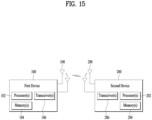
- a user equipment for performing an uplink (UL) transmission in a wireless communication system, comprising: at least one transceiver; at least one processor; and at least one memory operably connected to the at least one processor and configured to store instructions that, when executed, cause the at least one processor to perform operations.
- the operation may comprise: performing sensing on a plurality of beams, wherein each of the plurality of beams is sensed independently; performing, through at least one transceiver, the UL transmission through at least one beam sensed to be idle among the plurality of beams, wherein counter values for the each of the plurality of beams are set independently.
- the sensing on the plurality of beams are performed, simultaneously.
- the sensing on the plurality of beams is first type sensing, wherein the performing the UL transmission is further comprising: based on (i) a first beam among the plurality of beams being sensed to be idle based on the first type sensing before a transmission time of the UL transmission corresponding to the first beam and (ii) the UL transmission has not performed after the first type sensing: performing second type sensing on the first beam during a duration immediately before the transmission time; and performing the UL transmission based on that the first beam is sensed to be idle based on the second type sensing.
- the first type sensing is based on Random back-off counter, and wherein the second type sensing is not based on Random back-off counter.
- the method further comprising: based on the first beam being sensed to be busy based on the second type sensing, performing the first type sensing on the first beam.
- Each of the plurality of beams corresponds to an UL transmission among a plurality of UL transmissions, and wherein the plurality of UL transmissions is scheduled at the same time.
- an apparatus for performing an uplink (UL) transmission in a wireless communication system comprising: at least one processor; and at least one memory operably connected to the at least one processor and configured to store instructions that, when executed, cause the at least one processor to perform operations.
- the operations may comprise: performing sensing on a plurality of beams, wherein each of the plurality of beams is sensed independently; performing the UL transmission through at least one beam sensed to be idle among the plurality of beams, wherein counter values for the each of the plurality of beams are set independently.
- a computer-readable storage medium including at least one computer program causing at least one processor to perform an operation.
- the operation may comprise: performing sensing on a plurality of beams, wherein each of the plurality of beams is sensed independently; performing the UL transmission through at least one beam sensed to be idle among the plurality of beams, wherein counter values for the each of the plurality of beams are set independently.
- a method of performing a downlink (DL) transmission by a base station (BS) in a wireless communication system comprising: performing sensing on a plurality of beams, wherein each of the plurality of beams is sensed independently; performing the DL transmission through at least one beam sensed to be idle among the plurality of beams, wherein counter values for the each of the plurality of beams are set independently.
- DL downlink
- BS base station
- a base station for performing a downlink (DL) transmission in a wireless communication system, comprising: at least one transceiver; at least one processor; and at least one memory operably connected to the at least one processor and configured to store instructions that, when executed, cause the at least one processor to perform operations comprising: performing sensing on a plurality of beams, wherein each of the plurality of beams is sensed independently; performing, through at least one transceiver, the UL transmission through at least one beam sensed to be idle among the plurality of beams, wherein counter values for the each of the plurality of beams are set independently.
- a listen-before-talk (LBT) type to be performed from among wide-beam LBT and narrow-beam LBT based on random backoff counter-based Cat-3 LBT or Cat-4 LBT may be determined, and an energy detection (ED) threshold may be differently configured according to a transmission type (e.g., unicast or broadcast), so that multiple beams may be efficiently transmitted and LBT for minimizing interference with other signals may be performed.
- LBT listen-before-talk
- ED energy detection
- independent per-beam LBT for multibeam transmission of a TDM and/or SDM format is performed in directions of a plurality of beams in a channel occupancy time (COT)
- independent per-beam LBT may be performed in a direction of each beam or independent per-beam LBT may be performed in a direction of a representative beam selected, so that multibeam transmission may be efficiently performed in one COT.
- CG-PUSCH configured grant-physical uplink shared channel
- DG-PUSCH dynamic grant-physical uplink shared channel
- CDMA code division multiple access
- FDMA frequency division multiple access
- TDMA time division multiple access
- OFDMA orthogonal frequency division multiple access
- SC-FDMA single carrier frequency division multiple access
- CDMA may be implemented as a radio technology such as universal terrestrial radio access (UTRA) or CDMA2000.
- TDMA may be implemented as a radio technology such as global system for mobile communications (GSM)/general packet radio service (GPRS)/enhanced data rates for GSM evolution (EDGE).
- GSM global system for mobile communications
- GPRS general packet radio service
- EDGE enhanced data rates for GSM evolution
- OFDMA may be implemented as a radio technology such as institute of electrical and electronics engineers (IEEE) 802.11 (wireless fidelity (Wi-Fi)), IEEE 802.16 (worldwide interoperability for microwave access (WiMAX)), IEEE 802.20, evolved UTRA (E-UTRA), and so on.
- IEEE institute of electrical and electronics engineers
- Wi-Fi wireless fidelity
- WiMAX worldwide interoperability for microwave access
- WiMAX wireless fidelity
- E-UTRA evolved UTRA
- UTRA is a part of universal mobile telecommunications system
- 3rd generation partnership project (3GPP) long term evolution (LTE) is a part of evolved UMTS (E-UMTS) using E-UTRA
- LTE-advanced (LTE-A) is an evolution of 3GPP LTE.
- 3GPP new radio or new radio access technology (NR) is an evolved version of 3GPP LTE/LTE-A.
- NR new radio access technology
- enhanced mobile broadband eMBB
- massive machine type communication mMTC
- ultra-reliable and low latency communications URLLC
- 5G supports such diverse use cases in a flexible and reliable way.
- eMBB goes far beyond basic mobile Internet access and covers rich interactive work, media and entertainment applications in the cloud or augmented reality (AR).
- Data is one of the key drivers for 5G and in the 5G era, we may for the first time see no dedicated voice service.
- voice is expected to be handled as an application program, simply using data connectivity provided by a communication system.
- the main drivers for an increased traffic volume are the increase in the size of content and the number of applications requiring high data rates.
- Streaming services (audio and video), interactive video, and mobile Internet connectivity will continue to be used more broadly as more devices connect to the Internet.
- Cloud storage and applications are rapidly increasing for mobile communication platforms. This is applicable for both work and entertainment. Cloud storage is one particular use case driving the growth of uplink data rates. 5G will also be used for remote work in the cloud which, when done with tactile interfaces, requires much lower end-to-end latencies in order to maintain a good user experience. Entertainment, for example, cloud gaming and video streaming, is another key driver for the increasing need for mobile broadband capacity. Entertainment will be very essential on smart phones and tablets everywhere, including high mobility environments such as trains, cars and airplanes. Another use case is AR for entertainment and information search, which requires very low latencies and significant instant data volumes.
- 5G is one of areas that play key roles in enabling smart city, asset tracking, smart utility, agriculture, and security infrastructure.
- URLLC includes services which will transform industries with ultra-reliable/available, low latency links such as remote control of critical infrastructure and self-driving vehicles.
- the level of reliability and latency are vital to smart-grid control, industrial automation, robotics, drone control and coordination, and so on.
- 5G may complement fiber-to-the home (FTTH) and cable-based broadband (or data-over-cable service interface specifications (DOCSIS)) as a means of providing streams at data rates of hundreds of megabits per second to giga bits per second.
- FTTH fiber-to-the home
- DOCSIS data-over-cable service interface specifications
- VR and AR applications mostly include immersive sport games.
- a special network configuration may be required for a specific application program.
- game companies may have to integrate a core server with an edge network server of a network operator in order to minimize latency.
- the automotive sector is expected to be a very important new driver for 5G, with many use cases for mobile communications for vehicles. For example, entertainment for passengers requires simultaneous high capacity and high mobility mobile broadband, because future users will expect to continue their good quality connection independent of their location and speed.
- Other use cases for the automotive sector are AR dashboards. These display overlay information on top of what a driver is seeing through the front window, identifying objects in the dark and telling the driver about the distances and movements of the objects.
- wireless modules will enable communication between vehicles themselves, information exchange between vehicles and supporting infrastructure and between vehicles and other connected devices (e.g., those carried by pedestrians).
- Safety systems may guide drivers on alternative courses of action to allow them to drive more safely and lower the risks of accidents.
- the next stage will be remote-controlled or self-driving vehicles.
- Smart cities and smart homes often referred to as smart society, will be embedded with dense wireless sensor networks.
- Distributed networks of intelligent sensors will identify conditions for cost- and energy-efficient maintenance of the city or home.
- a similar setup may be done for each home, where temperature sensors, window and heating controllers, burglar alarms, and home appliances are all connected wirelessly.
- Many of these sensors are typically characterized by low data rate, low power, and low cost, but for example, real time high definition (HD) video may be required in some types of devices for surveillance.
- HD high definition
- a smart grid interconnects such sensors, using digital information and communications technology to gather and act on information. This information may include information about the behaviors of suppliers and consumers, allowing the smart grid to improve the efficiency, reliability, economics and sustainability of the production and distribution of fuels such as electricity in an automated fashion.
- a smart grid may be seen as another sensor network with low delays.
- the health sector has many applications that may benefit from mobile communications.
- Communications systems enable telemedicine, which provides clinical health care at a distance. It helps eliminate distance barriers and may improve access to medical services that would often not be consistently available in distant rural communities. It is also used to save lives in critical care and emergency situations.
- Wireless sensor networks based on mobile communication may provide remote monitoring and sensors for parameters such as heart rate and blood pressure.
- Wireless and mobile communications are becoming increasingly important for industrial applications. Wires are expensive to install and maintain, and the possibility of replacing cables with reconfigurable wireless links is a plausible opportunity for many industries. However, achieving this requires that the wireless connection works with a similar delay, reliability and capacity as cables and that its management is simplified. Low delays and very low error probabilities are new requirements that need to be addressed with 5G
- logistics and freight tracking are important use cases for mobile communications that enable the tracking of inventory and packages wherever they are by using location-based information systems.
- the logistics and freight tracking use cases typically require lower data rates but need wide coverage and reliable location information.
- FIG. 1 illustrates exemplary UL transmission operations of a UE.
- the UE may transmit an intended packet based on a DG ( FIG. 1(a) ) or based on a CG ( FIG. 1(b) ).
- the BS may dynamically allocate resources for UL transmission to the UE by PDCCH(s) (including DCI format 0_0 or DCI format 0_1). Further, the BS may allocate UL resources for initial HARQ transmission to the UE based on a configured grant (CG) method (similarly to SPS).
- CG configured grant
- a configured grant does not involve a PDCCH for a PUSCH transmission.
- UL resources for retransmission are explicitly allocated by PDCCH(s).
- an operation of preconfiguring UL resources without a dynamic grant (DG) e.g., a UL grant through scheduling DCI
- CG dynamic grant
- Two types are defined for the CG
- Resources for CGs may be shared between a plurality of UEs.
- a UL signal transmission based on a CG from each UE may be identified by time/frequency resources and an RS parameter (e.g., a different cyclic shift or the like). Therefore, when a UE fails in transmitting a UL signal due to signal collision, the BS may identify the UE and explicitly transmit a retransmission grant for a corresponding TB to the UE.
- K repeated transmissions including an initial transmission are supported for the same TB by a CG
- the same HARQ process ID is determined for K times repeated UL signals based on resources for the initial transmission.
- the redundancy versions (RVs) of a K times repeated TB have one of the patterns ⁇ 0, 2, 3, 1 ⁇ , ⁇ 0, 3, 0, 3 ⁇ , and ⁇ 0, 0, 0, 0 ⁇ .
- the UE performs repeated transmissions until one of the following conditions is satisfied:
- LAA licensed-assisted access
- LAA licensed-assisted access
- a stand-along (SA) operation is aimed in an NR cell of an unlicensed band (hereinafter, referred to as NR unlicensed cell (UCell)).
- NR unlicensed cell For example, PUCCH, PUSCH, and PRACH transmissions may be supported in the NR UCell.
- HARQ-ACK information may not be used to adjust a contention window (CW) size in a UL LBT procedure.
- a UL grant is received in the n-th subframe
- the first subframe of the most recent UL transmission burst prior to the (n-3)-th subframe has been configured as a reference subframe
- the CW size has been adjusted based on a new data indicator (NDI) for a HARQ process ID corresponding to the reference subframe.
- NDI new data indicator
- a method has been introduced of increasing the CW size to the next largest CW size of a currently applied CW size in a set for pre-agreed CW sizes under the assumption that transmission of a PUSCH has failed in the reference subframe due to collision with other signals or initializing the CW size to a minimum value (e.g., CWmin) under the assumption that the PUSCH in the reference subframe has been successfully transmitted without any collision with other signals.
- a minimum value e.g., CWmin
- CC component carrier
- RF radio frequency
- a different numerology e.g., SCS
- SCS numerology
- each UE may have a different maximum bandwidth capability.
- the BS may indicate to the UE to operate only in a partial bandwidth instead of the total bandwidth of the wideband CC.
- the partial bandwidth may be defined as a bandwidth part (BWP).
- a BWP may be a subset of contiguous RBs on the frequency axis.
- One BWP may correspond to one numerology (e.g., SCS, CP length, slot/mini-slot duration, and so on).
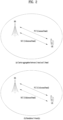
- FIG. 2 illustrates an exemplary wireless communication system supporting an unlicensed band applicable to the present disclosure.
- a cell operating in a licensed band is defined as an L-cell, and a carrier of the L-cell is defined as a (DL/LTL) LCC.
- a cell operating in an unlicensed band is defined as a U-cell, and a carrier of the U-cell is defined as a (DL/LTL) UCC.
- the carrier/carrier-frequency of a cell may refer to the operating frequency (e.g., center frequency) of the cell.
- a cell/carrier e.g., CC
- CC is commonly called a cell.
- the LCC and the UCC may be configured as a primary CC (PCC) and a secondary CC (SCC), respectively.
- the BS and the UE may transmit and receive signals on one UCC or on a plurality of carrier-aggregated UCCs as illustrated in FIG. 2(b) .
- the BS and UE may transmit and receive signals only on UCC(s) without using any LCC.
- PRACH, PUCCH, PUSCH, and SRS transmissions may be supported on a UCell.
- Signal transmission and reception operations in an unlicensed band as described in the present disclosure may be applied to the afore-mentioned deployment scenarios (unless specified otherwise).
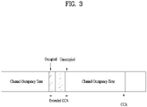
- the COT may be shared for transmission between the BS and corresponding UE(s).
- sharing a UE-initiated COT with the BS may mean an operation in which the UE assigns a part of occupied channels through random backoff counter-based LBT (e.g., Category 3 (Cat-3) LBT or Category 4 (Cat-4) LBT) to the BS and the BS performs DL transmission using a remaining COT of the UE, when it is confirmed that a channel is idle by success of LBT after performing LBT without random backoff counter (e.g., Category 1 (Cat-1) LBT or Category 2 (Cat-2) LBT) using a timing gap occurring before DL transmission start from a UL transmission end timing of the UE.
- random backoff counter-based LBT e.g., Category 3 (Cat-3) LBT or Category 4 (Cat-4) LBT
- the BS performs DL transmission using a remaining COT of the UE, when it is confirmed that a channel is idle by success of LBT after performing LBT without random backoff counter (e.g., Category 1 (Cat-1) L
- sharing a gNB-initiated COT with the UE may mean an operation in which the BS assigns a part of occupied channels through random backoff counter-based LBT (e.g., Cat-3 LBT or Cat-4 LBT) to the UE and the UE performs UL transmission using a remaining COT of the BS, when it is confirmed that a channel is idle by success of LBT after performing LBT without random backoff counter (e.g., Cat-1 LBT or Cat-2 LBT) using a timing gap occurring before UL transmission start from a DL transmission end timing of the BS.
- random backoff counter-based LBT e.g., Cat-3 LBT or Cat-4 LBT
- FIG. 3 illustrates an exemplary method of occupying resources in an unlicensed band.
- a communication node e.g., a BS or a UE operating in an unlicensed band should determine whether other communication node(s) is using a channel, before signal transmission.
- the communication node may perform a CAP to access channel(s) on which transmission(s) is to be performed in the unlicensed band.
- the CAP may be performed based on sensing.
- the communication node may determine whether other communication node(s) is transmitting a signal on the channel(s) by carrier sensing (CS) before signal transmission. Determining that other communication node(s) is not transmitting a signal is defined as confirmation of clear channel assessment (CCA).
- CCA confirmation of clear channel assessment
- the communication node may determine that the channel is busy, when detecting energy higher than the CCA threshold in the channel. Otherwise, the communication node may determine that the channel is idle. When determining that the channel is idle, the communication node may start to transmit a signal in the unlicensed band. CAP may be replaced with LBT.
- CCA threshold e.g., Xthresh
- RRC higher-layer
- Table 1 describes an exemplary CAP supported in NR-U.
- Type Explanation DL Type 1 CAP CAP with random backoff - time duration spanned by the sensing slots that are sensed to be idle before a downlink transmission(s) is random Type 2 CAP - Type 2A, 2B, 2C CAP without random backoff - time duration spanned by sensing slots that are sensed to be idle before a downlink transmission(s) is deterministic UL
- Type 1 CAP CAP with random backoff - time duration spanned by the sensing slots that are sensed to be idle before a downlink transmission(s) is random Type 2 CAP - Type 2A, 2B, 2C CAP without random backoff - time duration spanned by sensing slots that are sensed to be idle before a downlink transmission(s) is deterministic
- one cell (or carrier (e.g., CC)) or BWP configured for a UE may be a wideband having a larger bandwidth (BW) than in legacy LTE.
- BW bandwidth
- a BW requiring CCA based on an independent LBT operation may be limited according to regulations.
- a subband (SB) in which LBT is individually performed be defined as an LBT-SB.
- LBT-SB subband
- a plurality of LBT-SBs may be included in one wideband cell/BWP.
- a set of RBs included in an LBT-SB may be configured by higher-layer (e.g., RRC) signaling.
- one or more LBT-SBs may be included in one cell/BWP based on (i) the BW of the cell/BWP and (ii) RB set allocation information.
- a plurality of LBT-SBs may be included in the BWP of a cell (or carrier).
- An LBT-SB may be, for example, a 20-MHz band.
- the LBT-SB may include a plurality of contiguous (P)RBs in the frequency domain, and thus may be referred to as a (P)RB set.
- a UE performs a Type 1 or Type 2 CAP for a UL signal transmission in an unlicensed band.
- the UE may perform a CAP (e.g., Type 1 or Type 2) configured by a BS, for a UL signal transmission.
- CAP type indication information may be included in a UL grant (e.g., DCI format 0_0 or DCI format 0_1) that schedules a PUSCH transmission.
- the length of a time period spanned by sensing slots sensed as idle before transmission(s) is random.
- the Type 1 UL CAP may be applied to the following transmissions.
- FIG. 4 illustrates Type 1 CAP among channel access procedures of a UE for UL/DL signal transmission in a U-band applicable to the present disclosure.
- the UE may sense whether a channel is idle for a sensing slot duration in a defer duration Td. After a counter N is decremented to 0, the UE may perform a transmission (S434). The counter N is adjusted by sensing the channel for additional slot duration(s) according to the following procedure.
- Step 3) Sense the channel for an additional slot duration, and if the additional slot duration is idle (Y), go to step 4. Else (N), go to step 5 (S450).
- Step 5 Sense the channel until a busy sensing slot is detected within the additional defer duration Td or all slots of the additional defer duration Td are sensed as idle (S460).
- Step 6 If the channel is sensed as idle for all slot durations of the additional defer duration Td (Y), go to step 4. Else (N), go to step 5 (S470).
- Table 2 illustrates that mp, a minimum CW, a maximum CW, a maximum channel occupancy time (MCOT), and an allowed CW size applied to a CAP vary according to channel access priority classes.
- Channel Access Priority Class (p) mp CWmin ,p CWmax, p Tulmcot, p allowed CWp sizes 1 2 3 7 2 ms ⁇ 3,7 ⁇ 2 2 7 15 4ms ⁇ 7,15 ⁇ 3 3 15 1023 6 or 10 ms ⁇ 15,31,63,127,255,511, 1023 ⁇ 4 7 15 1023 6 or 10 ms ⁇ 15,31,63,127,255,511, 1023 ⁇ 4 7 15 1023 6 or 10 ms ⁇ 15,31,63,127,255,511, 1023 ⁇
- the defer duration Td includes a duration Tf (16us) immediately followed by mp consecutive slot durations where each slot duration Tsl is 9us, and Tf includes a sensing slot duration Tsl at the start of the 16-us duration.
- CWp is set to CWmin,p, and may be updated before Step 1 based on an explicit/implicit reception response to a previous UL burst (e.g., PUSCH) (CW size update). For example, CWp may be initialized to CWmin,p based on an explicit/implicit reception response to the previous UL burst, may be increased to the next higher allowed value, or may be maintained to be an existing value.
- Type 2 UL CAP the length of a time period spanned by sensing slots sensed as idle before transmission(s) is deterministic.
- Type 2 UL CAPs are classified into Type 2A UL CAP, Type 2B UL CAP, and Type 2C UL CAP.
- Tf includes a sensing slot at the start of the duration.
- Tf includes a sensing slot within the last 9us of the duration.
- the UE does not sense a channel before a transmission.
- the BS should succeed in an LBT operation to transmit a UL grant in the unlicensed band, and the UE should also succeed in an LBT operation to transmit the UL data. That is, only when both of the BS and the UE succeed in their LBT operations, the UE may attempt the UL data transmission. Further, because a delay of at least 4 msec is involved between a UL grant and scheduled UL data in the LTE system, earlier access from another transmission node coexisting in the unlicensed band during the time period may defer the scheduled UL data transmission of the UE. In this context, a method of increasing the efficiency of UL data transmission in an unlicensed band is under discussion.
- NR also supports CG type 1 and CG type 2 in which the BS preconfigures time, frequency, and code resources for the UE by higher-layer signaling (e.g., RRC signaling) or both of higher-layer signaling and L1 signaling (e.g., DCI). Without receiving a UL grant from the BS, the UE may perform a UL transmission in resources configured with type 1 or type 2.
- higher-layer signaling e.g., RRC signaling
- L1 signaling e.g., DCI
- Type 2 is a scheme of configuring the periodicity of a CG and a power control parameter by higher-layer signaling such as RRC signaling and indicating information about the remaining resources (e.g., the offset of an initial transmission timing, time/frequency resource allocation, a DMRS parameter, and an MCS/TBS) by activation DCI as L1 signaling.
- AUL autonomous uplink
- a CG of NR a HARQ-ACK feedback transmission method for a PUSCH that the UE has transmitted without receiving a UL grant and the presence or absence of UCI transmitted along with the PUSCH.
- a HARQ process is determined by an equation of a symbol index, a symbol periodicity, and the number of HARQ processes in the CG of NR
- explicit HARQ-ACK feedback information is transmitted in AUL downlink feedback information (AUL-DFI) in LTE LAA.
- AUL-DFI AUL downlink feedback information
- UCI including information such as a HARQ ID, an NDI, and an RV is also transmitted in AUL UCI whenever AUL PUSCH transmission is performed.
- the BS identifies the UE by time/frequency resources and DMRS resources used for PUSCH transmission, whereas in the case of LTE LAA, the BS identifies the UE by a UE ID explicitly included in the AUL UCI transmitted together with the PUSCH as well as the DMRS resources.
- the BS may perform one of the following U-band access procedures (e.g., channel access procedures (CAPs)) to transmit a DL signal in the U-band.
- U-band access procedures e.g., channel access procedures (CAPs)
- Type 1 DL CAP the length of a time duration spanned by sensing slots that are sensed to be idle before transmission(s) is random.
- the Type 1 DL CAP may be applied to the following transmissions:
- the BS may first sense whether a channel is idle for a sensing slot duration of a defer duration Td. Next, if a counter N is decremented to 0, transmission may be performed (S434). The counter N is adjusted by sensing the channel for additional slot duration(s) according to the following procedures.
- Step 3) Sense the channel for an additional slot duration, and if the additional slot duration is idle (Y), go to step 4. Else (N), go to step 5 (S450).
- Step 5 Sense the channel until a busy sensing slot is detected within the additional defer duration Td or all slots of the additional defer duration Td are sensed to be idle (S460).
- Step 6 If the channel is sensed to be idle for all slot durations of the additional defer duration Td (Y), go to step 4. Else (N), go to step 5 (S470).
- Table 3 illustrates that mp, a minimum CW, a maximum CW, an MCOT, and an allowed CW size, which are applied to a CAP, vary according to channel access priority classes.
- Channel Access Priority Class (p) mp CWmin ,p CWmax, p Tmcot,p allowed CWp sizes 1 1 3 7 2 ms ⁇ 3,7 ⁇ 2 1 7 15 3 ms ⁇ 7,15 ⁇ 3 3 15 63 8 or 10 ms ⁇ 15,31,63 ⁇ 4 7 15 1023 8 or 10 ms ⁇ 15,31,63,127,255,511,10 23 ⁇
- the defer duration Td includes a duration Tf (16 ⁇ s) immediately followed by mp consecutive sensing slot durations where each sensing slot duration Tsl is 9 ⁇ s, and Tf includes the sensing slot duration Tsl at the start of the 16- ⁇ s duration.
- CWp is set to CWmin,p, and may be updated (CW size update) before Step 1 based on HARQ-ACK feedback (e.g., ratio of ACK signals or NACK signals) for a previous DL burst (e.g., PDSCH).
- HARQ-ACK feedback e.g., ratio of ACK signals or NACK signals
- CWp may be initialized to CWmin,p based on HARQ-ACK feedback for the previous DL burst, may be increased to the next highest allowed value, or may be maintained at an existing value.
- Type 2 DL CAP In a Type 2 DL CAP, the length of a time duration spanned by sensing slots sensed to be idle before transmission(s) is deterministic.
- Type 2 DL CAPs are classified into Type 2A DL CAP, Type 2B DL CAP, and Type 2C DL CAP.
- the Type 2A DL CAP may be applied to the following transmissions.
- Tf includes the sensing slot at the start of the duration.
- the Type 2B DL CAP is applicable to transmission(s) performed by the BS after a gap of 16 ⁇ s from transmission(s) by the UE within shared channel occupancy.
- Tf includes a sensing slot within the last 9 ⁇ s of the duration.
- the Type 2C DL CAP is applicable to transmission(s) performed by the BS after a maximum of a gap of 16 ⁇ s from transmission(s) by the UE within shared channel occupancy. In the Type 2C DL CAP, the BS does not sense a channel before performing transmission.
- one cell (or carrier (e.g., CC)) or BWP configured for the UE may consist of a wideband having a larger BW than in legacy LTE.
- a BW requiring CCA based on an independent LBT operation may be limited according to regulations.
- a subband (SB) in which LBT is individually performed is defined as an LBT-SB
- a plurality of LBT-SBs may be included in one wideband cell/BWP.
- a set of RBs constituting an LBT-SB may be configured by higher-layer (e.g., RRC) signaling.
- one or more LBT-SBs may be included in one cell/BWP based on (i) the BW of the cell/BWP and (ii) RB set allocation information.
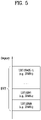
- FIG. 5 illustrates that a plurality of LBT-SBs is included in a U-band.
- a plurality of LBT-SBs may be included in the BWP of a cell (or carrier).
- An LBT-SB may be, for example, a 20-MHz band.
- the LBT-SB may include a plurality of contiguous (P)RBs in the frequency domain and thus may be referred to as a (P)RB set.
- a guard band (GB) may be included between the LBT-SBs. Therefore, the BWP may be configured in the form of ⁇ LBT-SB #0 (RB set #0) + GB #0 + LBT-SB #1 (RB set #1 + GB #1) + ... + LBT-SB #(K-1) (RB set (#K-1)) ⁇ .
- LBT-SB/RB indexes may be configured/defined to be increased as a frequency band becomes higher starting from a low frequency band.
- a massive multiple input multiple output (MIMO) environment in which the number of transmission/reception (Tx/Rx) antennas is significantly increased may be under consideration. That is, as the massive MIMO environment is considered, the number of Tx/Rx antennas may be increased to a few tens or hundreds.
- the NR system supports communication in an above 6 GHz band, that is, a millimeter frequency band.
- the millimeter frequency band is characterized by the frequency property that a signal is very rapidly attenuated according to a distance due to the use of too high a frequency band.
- BF beamforming
- FIG. 6 is a block diagram illustrating an exemplary transmitter and receiver for hybrid BF.
- a BF method is mainly considered, in which a BS or a UE transmits the same signal through multiple antennas by applying appropriate phase differences to the antennas and thus increasing energy only in a specific direction.
- Such BF methods include digital BF for generating a phase difference for digital baseband signals, analog BF for generating phase differences by using time delays (i.e., cyclic shifts) for modulated analog signals, and hybrid BF with digital BF and analog beamforming in combination.
- RF radio frequency
- TXRU transceiver unit
- TXRUs in all of about 100 antenna elements is less feasible in terms of cost. That is, a large number of antennas are required to compensate for rapid propagation attenuation in the millimeter frequency, and digital BF needs as many RF components (e.g., digital-to-analog converters (DACs), mixers, power amplifiers, and linear amplifiers) as the number of antennas.
- DACs digital-to-analog converters
- implementation of digital BF in the millimeter frequency band increases the prices of communication devices. Therefore, analog BF or hybrid BF is considered, when a large number of antennas are needed as is the case with the millimeter frequency band.
- Hybrid BF is an intermediate form of digital BF and analog BF, using B RF units fewer than Q antenna elements. In hybrid BF, the number of beam directions available for simultaneous transmission is limited to B or less, which depends on how B RF units and Q antenna elements are connected.
- the BM refers to a series of processes for acquiring and maintaining a set of BS beams (transmission and reception point (TRP) beams) and/or a set of UE beams available for DL and UL transmission/reception.
- the BM may include the following processes and terminology.
- the BM procedure may be divided into (1) a DL BM procedure using an SSB or CSI-RS and (2) a UL BM procedure using an SRS. Further, each BM procedure may include Tx beam sweeping for determining a Tx beam, and Rx beam sweeping for determining an Rx beam.
- the DL BM procedure may include (1) transmission of beamformed DL RSs (e.g., CSI-RS or SSB) from the BS and (2) beam reporting from the UE.
- beamformed DL RSs e.g., CSI-RS or SSB
- a beam report may include preferred DL RS ID(s) and reference signal received power(s) (RSRP(s)) corresponding to the preferred DL RS ID(s).
- ADL RS ID may be an SSB resource indicator (SSBRI) or a CSI-RS resource indicator (CRI).
- the UE may receive at least a list of up to M candidate transmission configuration indication (TCI) states for QCL indication by RRC signaling.
- M depends on a UE capability and may be 64.
- Each TCI state may be configured with one RS set.
- Table 4 describes an example of a TCI-State IE.
- the TC-State IE is related to a QCL type corresponding to one or two DL RSs.
- 'bwp-Id' identifies a DL BWP in which an RS is located
- 'cell' indicates a carrier in which the RS is located
- 'referencesignal' indicates reference antenna port(s) serving as a QCL source for target antenna port(s) or an RS including the reference antenna port(s).
- the target antenna port(s) may be for a CSI-RS, PDCCH DMRS, or PDSCH DMRS.
- the UE may receive a list of up to M TCI-State configurations to decode a PDSCH according to a detected PDCCH carrying DCI intended for a given cell.
- M depends on a UE capability.
- each TCI-State includes a parameter for establishing the QCL relationship between one or more DL RSs and a PDSCH DM-RS port.
- the QCL relationship is established with an RRC parameter qcl-Type1 for a first DL RS and an RRC parameter qcl-Type2 for a second DL RS (if configured).
- the QCL type of each DL RS is given by a parameter 'qcl-Type' included in QCL-Info and may have one of the following values.
- the NZP CSI-RS antenna port may be indicated/configured as QCLed with a specific TRS from the perspective of QCL-Type A and with a specific SSB from the perspective of QCL-Type D.
- the UE may receive the NZP CSI-RS using a Doppler value and a delay value which are measured in a QCL-TypeA TRS, and apply an Rx beam used to receive a QCL-Type D SSB for reception of the NZP CSI-RS
- beam reciprocity (or beam correspondence) between Tx and Rx beams may or may not be established according to the implementation of the UE. If the Tx-Rx beam reciprocity is established at both the BS and UE, a UL beam pair may be obtained from a DL beam pair. However, if the Tx-Rx beam reciprocity is established at neither the BS nor UE, a process for determining a UL beam may be required separately from determination of a DL beam pair.
- the BS may apply the UL BM procedure to determine a DL Tx beam without requesting the UE to report its preferred beam.
- the UL BM may be performed based on beamformed UL SRS transmission. Whether the UL BM is performed on a set of SRS resources may be determined by a usage parameter (RRC parameter). If the usage is determined as BM, only one SRS resource may be transmitted for each of a plurality of SRS resource sets at a given time instant.
- RRC parameter usage parameter
- the UE may be configured with one or more SRS resource sets (through RRC signaling), where the one or more SRS resource sets are configured by SRS-ResourceSet (RRC parameter).
- RRC parameter For each SRS resource set, the UE may be configured with K ⁇ 1 SRS resources, where K is a natural number, and the maximum value of K is indicated by SRS_capability.
- the UL BM procedure may also be divided into Tx beam sweeping at the UE and Rx beam sweeping at the BS similarly to DL BM.
- a beam may mean an area for performing a specific operation (e.g., LBT or transmission) by concentrating power in a specific direction and/or in a specific space.
- the UE or the BS may perform an operation such as LBT (Listen Before Talk)or transmission by targeting a specific area (i.e., a beam) corresponding to a specific space and/or a specific direction.
- LBT Listen Before Talk
- each beam may correspond to each space and/or each direction.
- the UE or the BS may use a spatial domain filter corresponding to each space and/or each direction in order to use each beam. That is, one spatial domain filter may correspond to one or more beams.
- the UE or the BS may perform an operation such as LBT or transmission using the spatial domain filter corresponding to a beam (or space and/or direction) to be used.
- the UE or the BS may perform LBT using a spatial domain filter corresponding to an LBT beam in a space and/or a direction for the corresponding LBT beam or perform DL/LTL transmission using a spatial domain filter corresponding to a Tx beam in a space and/or a direction for the corresponding Tx beam.
- the present disclosure proposes an efficient LBT method based on a multichannel access procedure applied to independent per-beam LBT for transmission in a plurality of beam directions through extension to the spatial domain.
- the present disclosure also proposes a method of differently configuring an energy detection (ED) threshold depending on whether the type of DL/UL transmission is broadcast transmission or unicast transmission, and a method of sharing a COT for each transmission type.
- ED energy detection
- LBT is a mechanism that prevents collision between transmissions by allowing transmission of a corresponding signal when a noise level is less than a certain level as a result of comparing a surrounding interference level measured by the BS and/or the UE that is to transmit signals with a specific threshold such as an ED threshold.
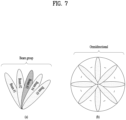
- FIG. 7 illustrates exemplary D-LBT and exemplary O-LBT.
- FIG. 7(a) illustrates D-LBT including specific beam direction LBT and/or beam group unit LBT
- FIG. 7(b) illustrates O-LBT
- a DL/UL signal/channel has been transmitted if it is determined that a channel is idle by performing a CAP (i.e., LBT) as described with reference to FIG. 7 .
- a CAP i.e., LBT
- an LBT band has been aligned with LBT bands of other RATs for coexistence with other RATs (e.g., Wi-Fi), and the CAP (i.e., LBT) has been performed omnidirectionally.
- nondirectional LBT has been performed in the legacy NR-U system.
- Rel-17 NR-U for transmitting the DL/LTL signal/channel in a higher band (e.g., a band of 52.6 GHz or higher) than a U-band of 7 GHz used in the legacy NR-U system may utilize directional LBT (D-LBT) which transmits the signal/channel by concentrating energy in a specific beam direction in order to overcome path loss larger than in the band of 7 GHz used in the legacy system. That is, in Rel-17 NR-U, the DL/UL signal/channel may be transmitted over wider coverage by reducing path loss through D-LBT, and efficiency may be improved even in coexistence with other RATs (e.g., WiGig).
- D-LBT directional LBT
- beam group unit LBT when a beam group consists of beams #1 to #5, performing LBT based on beams #1 to #5 may be referred to as beam group unit LBT.
- performing LBT through any one (e.g., beam #3) of beams #1 to #5 may be referred to as specific beam direction LBT.
- beams #1 to #5 may be continuous (or adjacent) beams but may also be discontinuous (or non-adjacent) beams.
- the number of beams included in the beam group is not necessarily plural, and a single beam may form one beam group.
- per-beam LBT may be performed, per-beam-group LBT may also be performed.
- beams #1 to #5 may cover a plurality of Tx beams multiplexed through time-division multiplexing (TDM) and/or spatial-division multiplexing (SDM), respectively.
- TDM time-division multiplexing
- SDM spatial-division multiplexing
- beam #1 may cover Tx beam #1 among the plural Tx beams multiplexed through TDM and/or SDM
- beam #2 may cover Tx beams #2 among the plural Tx beams
- beam #3 may cover Tx beam #3 among the plural of Tx beams
- beam #4 may cover Tx beam #4 among the plural Tx beams
- beam #5 may cover Tx beam #5 among the plural Tx beams.
- covering may mean that an area of a beam for performing LBT includes or is at least the same as an area on which a Tx beam corresponding to the corresponding beam has a valid effect (or interference).
- covering may mean performing energy measurement through a sensing beam for performing LBT including an area affected by the interference of a Tx beam.
- whether a channel is idle/busy may be determined by comparing energy measured through the sensing beam with an ED threshold.
- performing per-beam-group LBT may mean that LBT is simultaneously performed in a beam group unit for a plurality of Tx beams, multiplexed through TDM and/or SDM, corresponding to beams included in a beam group.
- a group LBT beam one beam for a beam group (hereinafter, a group LBT beam) may be formed and LBT may be simultaneously performed for all of a plurality of Tx beams using the group LBT beam.
- the group LBT beam may cover all Tx beams (e.g., Tx beam #1 to Tx beam #5) corresponding to the beam group.
- an area of the group LBT beam may include or be at least the same as all of areas on which each of the Tx beams (e.g., Tx beam #1 to Tx beam #5) has a valid effect (or interference).
- FIG. 7(b) illustrates O-LBT.
- O-LBT omnidirectional LBT
- a multi-antenna technique may be used. For example, narrow-beam transmission in which a signal is transmitted by concentrating energy in a specific direction, rather than omnidirectional transmission, may be performed.
- a CAP such as LBT described above
- beam-based transmission combined therewith needs to be considered.
- D-LBT may be performed only in the corresponding direction or LBT may be performed in units of a beam group including a beam of the corresponding direction. Then, if a channel is determined to be idle, transmission may be performed.
- the beam group may include a single beam or a plurality of beams. If the beam group includes omnidirectional beams, D-LBT may be extended to O-LBT.
- D-LBT or O-LBT based on random backoff counter-based LBT e.g., Cat-3 LBT or Cat-4 LBT
- LBT may be sequentially performed in each beam direction.
- a time required to perform LBT in all beam directions is increased, a relatively long time may be required to access a channel for starting transmission as compared with O-LBT.
- a representative beam direction may be determined among a plurality of narrow-beam directions in which LBT is to be performed by extending a multichannel access procedure of Rel-16 NR-U to the spatial domain. Then, random backoff counter-based LBT (e.g., Cat-3 LBT or Cat-4 LBT) may be performed only in the determined representative beam direction, and LBT (e.g., Cat-2 LBT) other than random backoff counter-based LBT may be performed in the remaining beam directions immediately before transmission. Transmission may be started when LBT is successful, so that a delay time required until start of transmission may be reduced.
- random backoff counter-based LBT e.g., Cat-3 LBT or Cat-4 LBT
- LBT e.g., Cat-2 LBT
- Transmission may be started when LBT is successful, so that a delay time required until start of transmission may be reduced.
- an ED threshold which is a criterion for determining whether a channel is idle or busy when LBT is performed, may be differently configured depending on whether transmission is broadcast transmission after wide-beam LBT (e.g., beam group LBT or O-LBT) or unicast transmission in a specific beam direction after narrow-beam LBT (D-LBT).
- wide-beam LBT e.g., beam group LBT or O-LBT
- D-LBT narrow-beam LBT
- an ED threshold of beam-swept and broadcast transmission such as transmission of a synchronization signal block (SSB) or a beam management sounding reference signal (SRS), may be set to be a high ED threshold relative to an ED threshold of unicast transmission performed only in a specific direction after narrow LBT, such as transmission of a physical downlink shared channel (PDSCH) or a physical uplink shared channel (PUSCH).
- SSB synchronization signal block
- SRS beam management sounding reference signal
- PDSCH physical downlink shared channel
- PUSCH physical uplink shared channel
- an LBT method to be used between wide-beam LBT and narrow-beam LBT may be determined by the capability of the UE or according to whether COT sharing is used (allowed).
- NR-based channel access schemes for an unlicensed band used in the present disclosure are classified as follows.
- the BS or the UE may perform specific beam direction LBT or beam group LBT (D-LBT), in addition to O-LBT, as the channel access procedure, so that a DL or UL signal/channel may be transmitted.
- D-LBT beam direction LBT or beam group LBT
- a COT obtained by performing LBT in all directions in a COT obtained by performing LBT in a specific direction, only for DL transmission and UL transmission having a correlation (e.g., QCL relation) with a beam direction in which LBT has been performed, transmission after Cat-2 LBT is desirably allowed and, for the other signals/channels, transmission after random backoff counter-based LBT (e.g., Cat-3 LBT or Cat-4 LBT) is desirably allowed.
- transmission after Cat-1 LBT instead of transmission after Cat-2 LBT, may also be allowed.
- LBT (e.g., Cat-2 LBT or Cat-1 LBT), which is not based on a random backoff counter, to be performed by the BS or the UE sharing a COT in the COT, may be performed in all directions or in a beam direction having a QCL relation with a beam direction that has been used to obtain the COT.
- the UE may be configured to monitor only a search space in the QCL relation with the specific beam direction or beam group direction in the corresponding COT.
- the BS may transmit a signal in 3 slots in a beam direction of A and then transmit a signal in the fourth slot in a beam direction of C.
- a Wi-Fi AP coexisting in a corresponding U-band may fail to detect the signal transmitted in the beam direction of A and determine that a channel is idle. After succeeding in LBT, the Wi-Fi AP may start to transmit and receive a signal. In this case, if the BS transmits a signal in the beam direction of C starting from slot #k+3, the signal may act as interference with a corresponding Wi-Fi signal.
- the BS may cause interference with another coexisting wireless node. Therefore, it may be desirable not to switch a Tx beam direction of a Tx burst that is transmitted after the BS succeeds in LBT.
- a method of signalling beam information to be used by the UE during UL transmission and reception by associating a DL signal and a UL signal is under consideration. For example, if there is a beam direction generated by the UE on a channel state information reference signal (CSI-RS) resource by associating the CSI-RS resource and a sounding reference signal (SRS) resource, when the UE transmits an SRS on the SRS resource linked with the CSI-RS resource (or when the UE transmits a PUSCH scheduled through a UL grant through which the SRS resource linked with the CSI-RS resource is signalled), the UE may transmit the UL signal using a Tx beam corresponding to a CSI-RS Rx beam.
- CSI-RS channel state information reference signal
- SRS sounding reference signal
- the relationship between a specific Rx beam and a specific Tx beam may be configured by the UE in implementation when there is beam correspondence capability of the UE.
- the relationship between the specific Rx beam and the specific Tx beam may be configured by training of the BS and the UE when there is no beam correspondence capability of the UE.
- COT sharing may be allowed between a DL Tx burst consisting of DL signals/channels in a spatial (partial) QCL relation with the DL signal and a UL Tx burst consisting of UL signals/channels in a spatial (partial) QCL relation with the UL signal associated with the DL signal.
- the UL signals/channels may include at least one or more of the following signals/channels:
- the DL signals/channels may include at least one or more of the following signals/channels:
- each proposed method to be described later may be combined with other proposed methods and be applied together therewith unless each proposed method conflicts with other proposed methods.
- FIG. 9 is a diagram illustrating an overall operation process of the UE or the BS for transmitting a DL/UL signal based on proposed methods of the present disclosure.
- the UE or the BS may perform first sensing based on at least one first sensing beam (S901).
- the at least one first sensing beam may be a beam that covers a plurality of Tx beams.
- One first sensing beam may cover all of the plural Tx beams, or a plurality of sensing beams may cover corresponding Tx beams, respectively.
- the first sensing may be performed based on at least one of [Proposed Method #1] to [Proposed Method #3].
- the UE or the BS may perform second sensing based on at least one second sensing beam (S903).
- the at least one second sensing beam may be a beam that covers the plural Tx beams.
- One second sensing beam may cover all of the plural Tx beams or a plurality of sensing beams may cover corresponding Tx beams, respectively.
- the second sensing may be performed based on at least one of [Proposed Method #1] to [Proposed Method #3].
- step S903 may be omitted when [Proposed Method #1] is implemented alone or continuous transmission between a configured grant-physical uplink shared channel (CG-PUSCH) and a dynamic grant-physical uplink shared channel (DG-PUSCH) is allowed in [Proposed Method #3] (e.g., conditions of [Embodiment #3-1] of [Proposed Method #3] are satisfied).
- CG-PUSCH configured grant-physical uplink shared channel
- DG-PUSCH dynamic grant-physical uplink shared channel
- the UE may transmit at least one UL signal corresponding to a Tx beam determined to be idle, or the BS may transmit at least one DL signal corresponding to a Tx beam determined to be idle (S905).
- the UL signal or the DL signal transmitted by the UE or the BS may be based on at least one of [Proposed Method #1] to [Proposed Method #3].
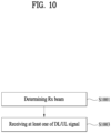
- FIG. 10 is a diagram illustrating an overall operation process of the UE or the BS for receiving a DL/UL signal based on proposed methods of the present disclosure.
- the UE or the BS may determine at least one Rx beam for receiving at least one DL signal or at least one UL signal through at least one Tx beam (S1001).
- the UE or the BS may receive the at least one DL signal or at least one UL signal transmitted based on at least one of [Method #1] to [Method #3] through the at least one Rx beam (S 1003).
- FIG. 11 is a diagram illustrating an overall operation process of a network for transmitting a DL/UL signal based on the proposed methods of the present disclosure.
- the UE or the BS may perform first sensing based on at least one first sensing beam (S1101).
- the at least one first sensing beam may be a beam that covers a plurality of Tx beams.
- One first sensing beam may cover all of the plural Tx beams or the plural first sensing beams may cover corresponding Tx beams, respectively.
- the first sensing may be performed based on at least one of [Proposed Method #1] to [Proposed Method #3].
- the UE or the BS may perform second sensing based on at least one second sensing beam (S1103).
- the at least one second sensing beam may be a beam that covers the plural Tx beams.
- One second sensing beam may cover all of the plural Tx beams or a plurality of sensing beams may cover corresponding Tx beams, respectively.
- the second sensing may be performed based on at least one of [Proposed Method #1] to [Proposed Method #3].
- step S1103 may be omitted when [Proposed Method #1] is implemented alone or continuous transmission between a CG-PUSCH and a DG-PUSCH is allowed in [Proposed Method #3] (e.g., conditions of [Embodiment #3-1] of [Proposed Method #3] are satisfied).
- the UE may transmit at least one UL signal corresponding to a Tx beam determined to be idle, or the BS may transmit at least one DL signal corresponding to a Tx beam determined to be idle (S1105).
- the UL signal or the DL signal transmitted by the UE or the BS may be based on at least one of [Proposed Method #1] to [Proposed Method #3].
- Method of selecting an LBT method according to the capability of the UE e.g., wide-beam LBT is performed when the UE is incapable of performing narrow-beam LBT
- the capability of the UE may mean a beam correspondence (BC) capability.
- BC beam correspondence
- the UE does not support the BC capability so that the UE requires UL beam management in order to satisfy BC requirements, only wide-beam LBT may be allowed for the UE. Further, only wide-beam LBT may always be allowed for the UE before UL beam management.
- Method of selecting the LBT method in consideration of COT sharing e.g., if COT is allowed (or performed), narrow-beam LBT is performed and, otherwise, wide-beam LBT is performed.
- Method of selecting the LBT method according to the Tx length of a Tx beam e.g., if the Tx length is longer than or equal to a threshold, narrow-beam LBT is performed and, if the Tx length is shorter than the threshold, wide-beam LBT is performed.
- a Tx beam (or reference beam) to be compared with the threshold may be determined based on a beam having the longest Tx length among beams to be multiplexed or based on a beam previously configured/indicated by the BS or a beam randomly selected by the UE.
- Method of selecting the LBT method according to the number of multiple beams to be transmitted in a COT e.g., if the number of Tx beams is less than a threshold, narrow-beam LBT is performed and, if the number of Tx beams is greater than the threshold, wide-beam LBT is performed.
- Method of differently configuring an ED threshold to be used to perform random backoff counter-based LBT e.g., Cat-3 LBT or Cat-4 LBT
- a COT sharing operation may be supported only when narrow-beam LBT is performed.
- the wide-beam may mean a beam group including a set of specific beams. If the beam group includes omnidirectional beams, this may mean O-LBT.
- the thresholds in [Embodiment #1-3] and [Embodiment #1-4] may be the same or different. The thresholds may be based on a value previously configured/indicated by the BS or defined in the standard.
- DL/LTL transmission with directionality may be performed in a specific beam direction through beamforming, rather than omnidirectionally. Accordingly, it may be efficient to perform LBT in a specific beam direction to be transmitted, rather than omnidirectionally, and to perform transmission in areas affected by interference of a corresponding beam.
- narrow-beam LBT performed only in a specific beam direction may not be supported.
- both narrow-beam LBT and wide-beam LBT may be applied.
- the BS or the UE may selectively determine the LBT method depending on whether to allow COT sharing.
- narrow-beam LBT may be sequentially performed in individual directions of beams to be multiplexed or LBT may be simultaneously performed in all directions of beams to be multiplexed.
- the type of LBT e.g., wide-beam LBT or narrow-beam LBT
- the ED threshold may be differently selected, when performing broadcast transmission such as transmission of an SSB or a beam management SRS or performing unicast transmission such as transmission of a PDSCH or a PUSCH.
- the type of LBT to be used for LBT among wide-beam LBT and narrow-beam LBT may be determined according to the Tx lengths of beams or the number of beams, to be multiplexed.
- the UE may always perform transmission in a specific beam direction.
- the UE that does not support narrow-beam LBT may always perform wide-beam LBT based on random backoff counter-based LBT (Cat-3 LBT or Cat-4 LBT) during multibeam transmission and start DL/LTL transmission when wide-beam LBT is successful.
- the capability of the UE may mean a BC capability, and only wide-beam LBT may be allowed for the UE that does not support BC capability so that the UE requires UL beam management in order to satisfy BC requirements.
- only wide-beam LBT may always be allowed for the UE before UL beam management.
- the UE that supports the corresponding capability may not be allowed to perform narrow-beam LBT and may be allowed to perform only wide-beam LBT.
- the UE that supports the corresponding capability i.e., a UE that does not support beamCorrespondenceWithoutUL-BeamSweeping
- narrow-beam LBT may also be performed after the UL beam management process.
- a COT sharing operation that may transfer a COT acquired by succeeding in random backoff counter-based LBT (e.g., Cat-3 LBT or Cat-4 LBT) may be allowed only when narrow-beam LBT based on random backoff counter-based LBT (e.g., Cat-3 LBT or Cat-4 LBT) is performed and may not be allowed when wide-beam LBT based on random backoff counter-based LBT (e.g., Cat-3 LBT or Cat-4 LBT) is performed.
- the BS or UE may perform LBT by selecting one of wide-beam LBT and narrow-beam LBT according to whether to transfer the remaining COT to another node after the BS or the UE performs transmission.
- the LBT method may be selected according to the Tx length of a Tx beam. For example, if the Tx length is longer than a threshold, narrow-beam LBT may be performed and, if the Tx length is shorter than the threshold, wide-beam LBT may be performed.
- the threshold serving as a criterion may be a value previously configured/indicated by the BS or defined in the standard.
- a Tx beam to be compared with the threshold may be determined according to one of the following criteria, i.e., based on (i) a beam having the longest Tx length among beams to be multiplexed, (ii) a beam previously configured/indicated by the BS, or (iii) a beam arbitrarily selected by the UE.
- the Tx length may be differently configured depending on the type of LBT performed.
- an MCOT of the BS or the UE may be differently configured depending on whether LBT performed is wide-beam LBT or narrow-beam LBT. For example, if the MCOT is up to 5 ms when the BS or the UE performs narrow-beam LBT, 3 ms, which is shorter than 5 ms, may be allowed as the MCOT length when the BS or the UE performs wide-beam LBT.
- the LBT method may be selected according to the number of multiple beams to be transmitted in the COT. For example, if the number of Tx beams is less than the threshold, narrow-beam LBT may be performed and, when the number of Tx beams is greater than the threshold, wide-beam LBT may be performed.
- the threshold which is a criterion, may be a value indicated by the BS or defined in the standard.
- An ED threshold which is a criterion to determine whether a channel is idle or busy when LBT is performed, may be differently configured depending on whether transmission is broadcast transmission after wide-beam LBT or unicast transmission after narrow-beam LBT. For example, since it is necessary to transmit, for example, an SSB or a beam management SRS in multiple beam directions through beam sweeping, the ED threshold to be used when wide-beam LBT based on random backoff counter-based LBT (e.g., Cat-3 LBT or Cat-4 LBT) is performed may be configured as a higher value than an ED threshold to be used when narrow-beam LBT based on random backoff counter-based LBT (e.g., Cat-3 LBT or Cat-4 LBT) performed for transmission in a specific beam direction is performed. In this case, COT sharing may not be allowed for wide-beam LBT and the COT sharing operation may be supported only when narrow-beam LBT is performed.
- random backoff counter-based LBT e.g., Cat-3 L
- an error in the operation of the UE may be eliminated and an operation suitable for the capacity of the UE may be performed, by determining whether to perform narrow-beam LBT based on whether the UE supports BC and whether beam management is configured.
- the capability of the UE fails to support narrow-beam LBT (i.e., when the UE does not have a capability to perform narrow-beam LBT)
- collision with other transmissions may be prevented by conservatively performing wide-beam LBT.
- one node may be prevented from excessively occupying a relatively wide range of space for a long time through wide-beam LBT, so that the influence of one node on transmission and reception of other nodes may be minimized.
- Random backoff counter-based LBT (e.g., Cat-3 LBT or Cat-4 LBT) is performed individually and simultaneously for beams.
- DL/LTL transmission corresponding to a beam direction in which LBT is completed first (e.g., LBT corresponding to a beam determined first to be idle) is not performed and is deferred through self-deferral until LBT of the remaining beam directions is completed.
- LBT of all beams is completed or immediately before LBT of a specific direction is completed (e.g., immediately before DL/UL transmission through multiple beams), it is shortly determined whether all beam directions are idle or busy.
- DL/UL transmission corresponding to at least one beam direction in which LBT is successful may be performed through SDM and/or TDM.
- idle or busy may be determined by performing single CCA slot LBT or LBT (e.g., Cat-2 LBT) rather than backoff counter-based LBT.
- beams for which random backoff counter-based LBT e.g., Cat-3 LBT or Cat-4 LBT
- CCA slot LBT or LBT e.g., Cat-2 LBT
- one sensing beam may correspond to one Tx beam among a plurality of Tx beams multiplexed by TDM and/or SDM.
- DL/UL transmission corresponding to the sensing beam may mean DL/UL transmission in which transmission is performed through a Tx beam corresponding to the sensing beam.
- each individual beam may have a backoff counter value according to the configuration/indication of the BS.
- the backoff counter value may be independently determined for each of the N sensing beams.
- the backoff counter value may be decreased only with respect to a sensing beam determined to be idle as a result of performing LBT simultaneously and in parallel upon the N sensing beams.
- all of multiplexed beams may have a common backoff counter value.
- the common backoff counter value may be determined for all of the N sensing beams.
- the common backoff counter value may be decreased only when it is determined that all of the N sensing beams are idle or it is determined that a certain number of sensing beams among the N sensing beams are idle as a result of performing LBT simultaneously and in parallel upon the N sensing beams.
- DL/UL transmission for SDM may be performed only when LBT for all beams is successful. If LBT for partial beams fails, DL/LTL transmission for all beams may be dropped and an LBT procedure may be performed again.
- SDM in the COT may mean that multiple beams are multiplexed using different spatial regions at the same time (e.g., the same slot) in the COT.
- TDM in the COT may mean that multiple beams are multiplexed at a plurality of times (e.g., a plurality of slots) in the COT. Therefore, if multiple beams are multiplexed by SDM and TDM, this may mean that a plurality of beam groups (including a part of multiple beams) multiplexed by SDM at the same time (e.g., the same slot) among multiple beams is multiplexed by TDM at a plurality of times (e.g., a plurality of slots) in the COT.
- a representative beam direction is determined among a plurality of multiplexed beams.
- Random backoff counter-based LBT e.g., Cat-3 LBT or Cat-4 LBT
- LBT e.g., Cat-2 LBT
- single CCA slot LBT is performed in the remaining beam directions immediately before LBT in the representative beam direction is completed (e.g., immediately before DL/LTL transmission through multiple beams).
- beams corresponding to beam directions in which LBT (e.g., Cat-2 LBT), rather than random backoff-based LBT, or single CCA slot LBT is successful may be transmitted through SDM and/or TDM.
- a beam upon which LBT is to be performed may mean a sensing beam.
- one sensing beam may correspond to one Tx beam among a plurality of Tx beams multiplexed by TDM and/or SDM.
- DL/LTL transmission corresponding to the sensing beam may mean DL/LTL transmission in which transmission is performed through a Tx beam corresponding to the sensing beam.
- [Embodiment #2-2] may be applied only when the UE or the BS has a capability to simultaneously perform LBT (e.g., Cat-3 LBT or Cat-2 LBT) in beam directions to be multiplexed by SDM and/or TDM.
- LBT e.g., Cat-3 LBT or Cat-2 LBT
- one contention window size (CWS) value may be updated based on A/N according to the configuration/indication of the BS or the CWS value may be independently updated for each beam.
- DL/UL transmission for SDM may be performed only when LBT for all beams is successful. If LBT for partial beams fails, DL/LTL transmission for all beams may be dropped and an LBT procedure may be performed again.
- the 3GPP TS 37.213 document related to a channel access procedure of Rel-16 NR-U discloses definition of multichannel access procedures and channels of Type A/B.
- Type A indicates a method of performing individual Cat-4 LBT for each channel.
- Type B indicates a method of performing Cat-4 LBT for one representative channel and performing single CCA slot LBT or Cat-2 LBT for the remaining channels immediately before Cat-4 LBT of the representative channel is completed, thereby performing DL/UL transmission for channels for which LBT is successful.
- the concept of a multichannel access procedure of Type A/B may be extensively applied to the spatial domain so that the multichannel access procedure may be used when independent per-beam LBT is performed based on random backoff counter-based LBT (e.g., Cat-3 LBT or Cat-4 LBT) for transmission of multiple beams multiplexed by TDM and/or SDM.
- random backoff counter-based LBT e.g., Cat-3 LBT or Cat-4 LBT
- random backoff counter-based LBT (e.g., Cat-3 LBT or Cat-4 LBT) is performed individually and simultaneously for a plurality of beams to be transmitted through SDM and/or TDM.
- LBT corresponding to a beam determined first to be idle
- DL/LTL transmission corresponding to the beam direction in which LBT is completed first is not performed and is deferred through self-deferral until LBT of the remaining beam directions is completed.
- idle or busy may be determined by performing single CCA slot LBT or Cat-2 LBT which is not based on random backoff.
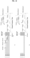
- Tx beam #1 to Tx beam #4 corresponding to four beams from beam #1 to beam #4, respectively, are scheduled through SDM and/or TDM in a COT.
- beams #1 to #4 may mean sensing beams corresponding to the four Tx beams, respectively.
- beams #1 to #4 may mean sensing beams #1 to #4, respectively.
- the BS or the UE may simultaneously start random backoff counter-based LBT (e.g., Cat-3 LBT or Cat-4 LBT) for the four beams from beam #1 to beam #4. If LBT for beam #1 is completed earlier than LBT for beams #2 to #4, DL/UL transmission through Tx beam #1 corresponding to beam #1 does not immediately start. In other words, DL/UL transmission through Tx beam #1 is not performed until LBT for beams #2 to #4 is completed and DL/LTL transmission through Tx beam #1 may wait through self-deferral.
- LBT random backoff counter-based LBT
- single CCA slot LBT or LBT (e.g., Cat-2 LBT), other than random backoff-based LBT, is performed immediately before an LBT ending timing for beam #4 which is completed last or immediately before DL/LTL transmission multiplexed by SDM and/or TDM (e.g., immediately before the COT including DL/LTL transmission multiplexed by SDM and/or TDM starts) to determine whether the beams are idle or busy. If it is determined that beams #1 to #4 are idle, DL/LTL transmission multiplexed by SDM and/or TDM may be performed in the corresponding COT.
- LBT ending timing for beam #4 which is completed last or immediately before DL/LTL transmission multiplexed by SDM and/or TDM (e.g., immediately before the COT including DL/LTL transmission multiplexed by SDM and/or TDM starts) to determine whether the beams are idle or busy. If it is determined that beams #1 to #4 are idle, DL/LTL transmission multiplexed by SDM
- random backoff-based LBT e.g., Cat-3 LBT or Cat-4 LBT
- at least one beam e.g., beam #4
- random backoff-based LBT fails
- the COT starts or until a predetermined time from a time immediately before the COT starts e.g., until a time required to perform Cat-2 LBT from a time immediately before the COT starts
- only single CCA slot or LBT e.g., Cat-2 LBT
- other than random backoff-based LBT is performed for the remaining beams (e.g., beam #1 to beam #3), except for the failed beam, to determine whether corresponding beams are idle or busy. If it is determined that beam #1 to beam #3 are idle, DL/LTL transmission multiplexed by SDM and/or TDM may be performed in the corresponding COT.
- the single CCA slot refers to a unit to perform channel measurement in order to determine whether a channel is idle/busy when random backoff counter-based LBT (e.g., Cat-3 LBT or Cat-4 LBT) is performed.
- random backoff counter-based LBT e.g., Cat-3 LBT or Cat-4 LBT
- the backoff counter value may be decreased by one.
- each individual beam may have the backoff counter value according to the configuration/indication of the BS.
- the backoff counter value may be independently determined for each of the N sensing beams.
- the backoff counter value may be decreased only for a sensing beam determined to be idle as a result of performing LBT upon the N sensing beams simultaneously and in parallel.
- all of the multiplexed beams may have a common backoff counter value.
- the common backoff counter value may be determined for all of the N sensing beams.
- the common backoff counter value may be decreased only when it is determined that all of the N sensing beams are idle or it is determined that a certain number of sensing beams among the N sensing beams are idle as a result of performing LBT simultaneously and in parallel upon the N sensing beams.
- DL/UL transmission for SDM may be performed only when LBT for all beams is successful. If LBT for partial beams fails, DL/UL transmission for all beams may be dropped and an LBT procedure may be performed again.
- DL/UL signals may be predictably transmitted at scheduling timings in the same COT through multiplexed Tx beams.
- DL/LTL transmission may be performed at the scheduling timings of the DL/LTL signals, thereby reducing predictability and complexity of transmission.
- LBT is performed upon all sensing beams corresponding to all the Tx beams, so that the reliability of a measurement result for the Tx beams may be increased and collision with other signals may be minimized.
- a representative beam direction is determined among a plurality of beams to be transmitted through SDM and/or TDM.
- Random backoff counter-based LBT e.g., Cat-3 LBT or Cat-4 LBT
- LBT e.g., Cat-2 LBT
- single CCA slot LBT is performed in the remaining beam directions immediately before LBT in the representative beam direction is completed (e.g., immediately before DL/UL transmission through multiple beams).
- DL/LTL transmission corresponding to beam directions in which LBT (e.g., Cat-2 LBT), rather than random backoff-based LBT, or single CCA slot LBT is successful may be performed through SDM and/or TDM.
- FIG. 12(b) a situation in which beam #4 among beams #1 to #4 is determined as a representative beam is illustrated.
- random backoff counter-based LBT Cat-3 LBT or Cat-4 LBT
- LBT e.g., Cat-2 LBT
- single CCA slot LBT is performed for beam #1 to beam #4 immediately before LBT for beam #4 is completed (e.g., immediately before DL/LTL transmission through multiple beams).
- DL/LTL transmission corresponding to beam directions that have succeeded in single CCA slot LBT or LBT (e.g., Cat-2 LBT), rather than random backoff-based LBT may be performed through SDM and/or TDM in the COT.
- beam #1 to beam #4 may mean sensing beams corresponding to four Tx beams, respectively.
- beams #1 to #4 may mean sensing beam #1 to sensing beam #4, respectively.
- the direction of the representative beam to be subjected to random backoff counter-based LBT may be determined by applying one method among 1) the direction of a beam to be transmitted first in the case of TDM, 2) the direction of a beam having the largest EIRP value, 3) a beam direction arbitrarily selected by the UE, 4) a beam direction previously configured/indicated by the BS, and 5) a beam direction in which the largest backoff counter value is determined.
- the direction of the representative beam may be applied only when the UE or the BS has a capability to simultaneously perform LBT (e.g., Cat-3 LBT or Cat-2 LBT) in beam directions to be subject to SDM and/or TDM.
- one CWS value may be updated based on A/N or CWS values may be independently updated for respective beams, according to the configuration/indication of the BS.
- DL/UL transmission for SDM may be performed only when LBT for all beams is successful. If LBT for partial beams fails, DL/LTL transmission for all beams may be dropped and an LBT procedure may be performed again.
- a DG-PUSCH may be scheduled in slot N+k+m through downlink control information (DCI) while the UE performs LBT (e.g., Cat-3 LBT or Cat-4 LBT) in order to transmit a CG-PUSCH in slot (N+k) and slot (N+k+1).
- LBT e.g., Cat-3 LBT or Cat-4 LBT
- DG-PUSCH scheduling may be confirmed through the DCI before LBT is performed or LBT is successful.
- DG-PUSCH scheduling may be confirmed through the DCI after LBT is successful, before the CG-PUSCH is transmitted, or after the CG-PUSCH is transmitted.
- a transmission direction of the CG-PUSCH may be preconfigured through spatialrelationinfo or may be indicated through an SRS resource indicator (SRI) field in activation DCI.
- SRI SRS resource indicator
- the transmission direction of the CG-PUSCH may be indicated through a UL TCI state.
- DG-PUSCH transmission may be continuously performed immediately after CG-PUSCH transmission without LBT, when (i) there is no gap between the ending symbol of a CG-PUSCH and the starting symbol of a DG-PUSCH on the time axis, (ii) the bandwidth of the CG-PUSCH transmitted on the frequency axis and the bandwidth of the scheduled DG-PUSCH are the same or the bandwidth to which the DG-PUSCH is allocated is a subset of the bandwidth to which the CG-PUSCH is allocated, and (iii) a Tx beam direction indicated for the DG-PUSCH is included in a Tx beam direction of the CG-PUSCH or the Tx beam direction indicated for the DG-PUSCH is equal to the Tx beam direction of the CG-PUSCH.
- the total sum of transmission lengths of the DG-PUSCH and the CG-PUSCH should not exceed an MCOT.
- symbols of at least one last CG-PUSCH prior to symbol i of slot n located before scheduled DG-PUSCHs may be dropped according to the mechanism of Clause 11.1 of 3GPP TS 38.213, as described in Clause 4.2.1.0.1 of 3GPP TS 37.213, when (i) there is a gap between the ending symbol of the CG-PUSCH and the starting symbol of the DG-PUSCH on the time axis, (ii) the bandwidth of the CG-PUSCH transmitted on the frequency axis and the bandwidth of the scheduled DG-PUSCH are not the same or the bandwidth to which the DG-PUSCH is allocated is not a subset of the bandwidth of the CG-PUSCH, or (iii) a beam direction indicated for the DG-PUSCH is not included in a Tx beam direction of the CG-PUSCH or the beam direction indicated for the DG-PUSCH is not equal to the Tx beam direction of the CG-
- a value of each of X, Y, and Z for X symbols, Y CG-PUSCHs, or Z slots, to be dropped for the LBT gap may use a value specified in the specification or a value previously configured/indicated by the BS through a higher layer signal (e.g., radio resource control (RRC)), a physical layer signal (e.g., DCI), or a combination of the higher layer signal and the physical layer signal.
- RRC radio resource control
- DCI physical layer signal
- DG-PUSCH to CG-PUSCH back-to-back transmission may be performed by changing the order, i.e., the CG-PUSCH to the DG-PUSCH or the DG-PUSCH to the CG-PUSCH.
- the UE may drop transmission of the CG-PUSCH following the DG-PUSCH.
- the priority of the DG-PUSCH is higher than that of the CG-PUSCH, this may be interpreted as follows.
- including the Tx beam direction of the DG-PUSCH in the Tx beam direction of the CG-PUSCH may mean that the Tx beam of the CG-PUSCH has a relatively large bandwidth relative to the Tx beam of the DG-PUSCH Tx beam, so that the Tx beam of the CG-PUSCH includes all of an interference area in which the DG-PUSCH has an effect on interference when the DG-PUSCH is transmitted in a specific beam direction.
- the beam directions of the CG-PUSCH and the DG-PUSCH are the same, this may mean that the beam directions indicated to the CG-PUSCH and the DG-PUSCH are indicated by the same spatialrelationinfo, the same SRI field, or the same joint TCI state (UL TCI state in the case of a DL/UL separate TCI).
- LTE LAA when the DG-PUSCH is scheduled with an AUL-PUSCH (autonomous UL access) in consecutive subframes without a gap, a transmission operation without LBT is supported (Clause 4.2.1 of 3GPP TS 37.213).
- the DG-PUSCH is being transmitted based on Cat-4 LBT in NR-U, if the DG-PUSCH is consecutively scheduled with a CG time axis resource configured for the UE without a gap (i.e., CG-DG back- to-back scheduling), the DG-PUSCH may be transmitted without LBT.
- a plurality of LBT subbands may be included in the bandwidth of the CG resource because the bandwidth of the CG resource configured for the UE is larger than 20 MHz, unlike LTE. Therefore, in order to continuously transmit the DG-PUSCH without LBT using a COT obtained through the CG-PUSCH, the frequency band of the scheduled DG-PUSCH should be included in the frequency band of the CG-PUSCH.
- the LBT subband of the DG-PUSCH should be a subset of the LBT subband of the CG-PUSCH or the LBT subband of the DG-PUSCH should be the same as the LBT subband of the CG-PUSCH.
- the DG-PUSCH may be transmitted immediately after the CG-PUSCH without LBT. For example, in the case of FIG.
- the DG-PUSCH may be transmitted without LBT immediately after the CG-PUSCH.
- a UE is scheduled by a UL grant received from an eNB on a channel to transmit a PUSCH transmission(s) starting from subframe n on the same channel using Type 1 channel access procedure and if at least for the first scheduled subframe occupies N RB UL resource blocks and the indicated PUSCH starting position is OFDM symbol zero, and if the UE starts autonomous UL transmissions before subframe n using Type 1 channel access procedure on the same channel, the UE may transmit UL transmission(s) according to the received UL grant from subframe n without a gap, if the priority class value of the performed channel access procedure is larger than or equal to priority class value indicated in the UL grant, and the autonomous UL transmission in the subframe preceding subframe n shall end at the last OFDM symbol of the subframe regardless of the higher layer parameter endingSymbolAUL.
- the sum of the lengths of the autonomous UL transmission(s) and the scheduled UL transmission(s) shall not exceed the maximum channel occupancy time corresponding to the priority class value used to perform the autonomous uplink channel access procedure. Otherwise, the UE shall terminate the ongoing autonomous UL transmission at least one subframe before the start of the UL transmission according to the received UL grant on the same channel.
- a UE For UL transmission(s) following configured grant UL transmission(s), the following are applicable: - If a UE is scheduled to transmit UL transmission(s) starting from symbol i in slot n using Type 1 channel access procedures without CP extension with a corresponding CAPC, and if the UE starts configured grant UL transmissions before symbol i in slot n using Type 1 channel access procedures with a corresponding CAPC, and the scheduled UL transmission(s) occupies all the RBs of the same channels occupied by the configured grant UL transmission(s) or all the RBs of a subset thereof, the UE may directly continue to transmit the scheduled UL transmission(s) to the corresponding CAPC from symbol i in slot n without a gap, if the CAPC value of the performed channel access procedure is larger than or equal to the CAPC value corresponding to the scheduled UL transmission(s).
- the sum of the transmission durations of the configured grant UL transmission(s) and the scheduled UL transmission(s) shall not exceed the MCOT duration corresponding to the CAPC value used to transmit the configured grant UL transmission(s). Otherwise, the UE shall terminate the configured grant UL transmission(s) by dropping the transmission on the symbols of at least the last configured grant UL transmission before symbol i in slot n and attempt to transmit the scheduled UL transmission(s) according to the corresponding CAPC.
- the symbols of the PUSCH transmission with a configured grant in a slot is dropped according to the mechanism in Clause 11.1 of [7, TS 38.213] relative to a last symbol of a CORESET where the UE detected the scheduling DCI. In this case, if the UE cannot terminate the configured grant UL transmission(s), the UE ignores the scheduling DCI.
- back-to-back transmission may be performed without LBT if the scheduled DG-PUSCH during transmission of the CG-PUSCH satisfies specific conditions.
- transmission/reception of a specific beam direction should be considered in addition to time and frequency conditions in NR-U, additional conditions for Tx beam directions of the CG-PUSCH and the DG-PUSCH need to be considered.
- DG-PUSCH transmission may be continuously performed immediately after CG-PUSCH transmission without LBT, when (i) there is no gap between the ending symbol of the CG-PUSCH and the starting symbol of the DG-PUSCH on the time axis, (ii) the bandwidth of the CG-PUSCH transmitted on the frequency axis and the bandwidth of the scheduled DG-PUSCH are the same or the bandwidth to which the DG-PUSCH is allocated is a subset of the bandwidth to which the CG-PUSCH is allocated, and (iii) a Tx beam direction indicated for the DG-PUSCH is included in a Tx beam direction of the CG-PUSCH or the Tx beam direction indicated for the DG-PUSCH is equal to the Tx beam direction of the CG-PUSCH.
- including the Tx beam direction of the DG-PUSCH in the Tx beam direction of the CG-PUSCH may mean that the Tx beam of the CG-PUSCH has a relatively large bandwidth relative to the Tx beam of the DG-PUSCH Tx beam, so that the Tx beam of the CG-PUSCH includes all of an interference area in which the DG-PUSCH has an effect on interference when the DG-PUSCH is transmitted in a specific beam direction.
- the beam directions of the CG-PUSCH and the DG-PUSCH are the same, this may mean that the beam directions indicated to the CG-PUSCH and the DG-PUSCH are indicated by the same spatialrelationinfo, the same SRI field, or the same joint TCI state (UL TCI state in the case of a DL/UL separate TCI).
- the total sum of transmission lengths of the DG-PUSCH and the CG-PUSCH should not exceed an MCOT.
- conditions incapable of performing CG-DG PUSCH back-to-back transmission may be considered with respect to a Tx beam direction in addition to the time and frequency conditions of NR-U.
- the DG-PUSCH is incapable of being transmitted without LBT, when (i) there is a gap between the ending symbol of the CG-PUSCH and the starting symbol of the DG-PUSCH on the time axis, (ii) the bandwidth of the CG-PUSCH transmitted on the frequency axis and the bandwidth of the scheduled DG-PUSCH are not the same or the bandwidth to which the DG-PUSCH is allocated is not a subset of the bandwidth of the CG-PUSCH, or (iii) a beam direction indicated for the DG-PUSCH is not included in a Tx beam direction of the CG-PUSCH or the Tx beam direction indicated for the DG-PUSCH is not equal to the Tx beam direction of the CG-PUSCH.
- the UE may drop symbols of at least one last CG-PUSCH prior to symbol i of slot n located before scheduled DG-PUSCHs according to the mechanism of Clause 11.1 of 3GPP TS 38.213, as described in Clause 4.2.1.0.1 of 3GPP TS 37.213.
- the same method may be applied even when the order of the CG-PUSCH and the DG-PUSCH is reversed, i.e., even in the case of DG-CG back-to-back transmission.
- the CG-PUSCH may be continuously transmitted immediately after DG-PUSCH transmission is ended without LBT.
- the UE may give up CG-PUSCH transmission instead of dropping the symbol of the DG-PUSCH as in [Embodiment #2-2].
- UL transmission may be performed through a space out of an interference region of a beam upon which LBT has already been performed, as described with reference to FIG. 8 , by allowing continuous transmission between the CG-PUSCH and the DG-PUSCH through the same beam as the beam on which LBT is performed or a beam included in a beam region in which LBT is performed, so that interference with other radio nodes may be prevented.
- random backoff-based LBT e.g., Cat-3 LBT or Cat-4 LBT
- a transmission opportunity of the DG-PUSCH may be increased by preventing transmission failure and delay of the DG-PUSCH due to LBT failure.
- FIG. 14 illustrates a communication system 1 applied to the present disclosure.
- the communication system 1 applied to the present disclosure includes wireless devices, BSs, and a network.
- a wireless device is a device performing communication using radio access technology (RAT) (e.g., 5G NR (or New RAT) or LTE), also referred to as a communication/radio/5G device.
- RAT radio access technology
- the wireless devices may include, not limited to, a robot 100a, vehicles 100b-1 and 100b-2, an extended reality (XR) device 100c, a hand-held device 100d, a home appliance 100e, an IoT device 100f, and an artificial intelligence (AI) device/server 400.
- RAT radio access technology
- XR extended reality
- AI artificial intelligence
- the vehicles may include a vehicle having a wireless communication function, an autonomous driving vehicle, and a vehicle capable of vehicle-to-vehicle (V2V) communication.
- the vehicles may include an unmanned aerial vehicle (UAV) (e.g., a drone).
- UAV unmanned aerial vehicle
- the XR device may include an augmented reality (AR)/virtual reality (VR)/mixed reality (MR) device and may be implemented in the form of a head-mounted device (HMD), a head-up display (HUD) mounted in a vehicle, a television (TV), a smartphone, a computer, a wearable device, a home appliance, a digital signage, a vehicle, a robot, and so on.
- AR augmented reality
- VR virtual reality
- MR mixeded reality
- the hand-held device may include a smartphone, a smartpad, a wearable device (e.g., a smartwatch or smartglasses), and a computer (e.g., a laptop).
- the home appliance may include a TV, a refrigerator, a washing machine, and so on.
- the IoT device may include a sensor, a smartmeter, and so on.
- the BSs and the network may be implemented as wireless devices, and a specific wireless device 200a may operate as a BS/network node for other wireless devices.
- the wireless devices 100a to 100f may be connected to the network 300 via the BSs 200.
- An AI technology may be applied to the wireless devices 100a to 100f, and the wireless devices 100a to 100f may be connected to the AI server 400 via the network 300.
- the network 300 may be configured using a 3G network, a 4G (e.g., LTE) network, or a 5G (e.g., NR) network.
- the wireless devices 100a to 100f may communicate with each other through the BSs 200/network 300, the wireless devices 100a to 100f may perform direct communication (e.g., sidelink communication) with each other without intervention of the BSs/network.
- the vehicles 100b-1 and 100b-2 may perform direct communication (e.g.
- V2V/vehicle-to-everything (V2X) communication may perform direct communication with other IoT devices (e.g., sensors) or other wireless devices 100a to 100f.
- Wireless communication/connections 150a, 150b, and 150c may be established between the wireless devices 100a to 100fBS 200 and between the BSs 200.
- the wireless communication/connections may be established through various RATs (e.g., 5G NR) such as UL/DL communication 150a, sidelink communication 150b (or, D2D communication), or inter-BS communication (e.g. relay or integrated access backhaul(IAB)).
- RATs e.g., 5G NR
- Wireless signals may be transmitted and received between the wireless devices, between the wireless devices and the BSs, and between the BSs through the wireless communication/connections 150a, 150b, and 150c.
- signals may be transmitted and receive don various physical channels through the wireless communication/connections 150a, 150b and 150c.
- various configuration information configuring processes various signal processing processes (e.g., channel encoding/decoding, modulation/demodulation, and resource mapping/demapping), and resource allocation processes, for transmitting/receiving wireless signals, may be performed based on the various proposals of the present disclosure.
- various signal processing processes e.g., channel encoding/decoding, modulation/demodulation, and resource mapping/demapping
- resource allocation processes for transmitting/receiving wireless signals
- FIG. 15 illustrates wireless devices applicable to the present disclosure.
- a first wireless device 100 and a second wireless device 200 may transmit wireless signals through a variety of RATs (e.g., LTE and NR).
- RATs e.g., LTE and NR
- the first wireless device 100 and the second wireless device 200 ⁇ may correspond to ⁇ the wireless device 100x and the BS 200 ⁇ and/or ⁇ the wireless device 100x and the wireless device 100x ⁇ of FIG 14 .
- the first wireless device 100 may include one or more processors 102 and one or more memories 104, and further include one or more transceivers 106 and/or one or more antennas 108.
- the processor(s) 102 may control the memory(s) 104 and/or the transceiver(s) 106 and may be configured to implement the descriptions, functions, procedures, proposals, methods, and/or operation flowcharts disclosed in this document.
- the processor(s) 102 may process information in the memory(s) 104 to generate first information/signals and then transmit wireless signals including the first information/signals through the transceiver(s) 106.
- the processor(s) 102 may receive wireless signals including second information/signals through the transceiver(s) 106 and then store information obtained by processing the second information/signals in the memory(s) 104.
- the memory(s) 104 may be connected to the processor(s) 102 and may store various pieces of information related to operations of the processor(s) 102.
- the memory(s) 104 may store software code including instructions for performing all or a part of processes controlled by the processor(s) 102 or for performing the descriptions, functions, procedures, proposals, methods, and/or operation flowcharts disclosed in this document.
- the processor(s) 102 and the memory(s) 104 may be a part of a communication modem/circuit/chip designed to implement RAT (e.g., LTE or NR).
- the transceiver(s) 106 may be connected to the processor(s) 102 and transmit and/or receive wireless signals through the one or more antennas 108.
- Each of the transceiver(s) 106 may include a transmitter and/or a receiver.
- the transceiver(s) 106 may be interchangeably used with radio frequency (RF) unit(s).
- the wireless device may be a communication modem/circuit/chip.
- the at least one memory 104 may be a computer-readable storage medium and may store instructions or programs. The instructions or programs may cause, when executed, the at least one processor operably connected to the at least one memory to perform operations according to embodiments or implementations of the present disclosure, related to the following operations.
- the processor 102 may perform first sensing based on at least one first sensing beam.
- the at least one first sensing beam may be a beam that covers a plurality of Tx beams.
- One first sensing beam may cover all of the plural of Tx beams, or a plurality of first sensing beams may cover corresponding Tx beams, respectively.
- the first sensing may be performed based on at least one of [Proposed Method #1] to [Proposed Method #3].
- the processor 102 may perform second sensing based on at least one second sensing beam.
- the at least one second sensing beam may be a beam that covers the plural Tx beams.
- One second sensing beam may cover all of the plural Tx beams or a plurality of sensing beams may cover corresponding Tx beams, respectively.
- the second sensing may be performed based on at least one of [Proposed Method #1] to [Proposed Method #3]. Meanwhile, performing the second sensing may be omitted when [Proposed Method #1] is implemented alone or when continuous transmission between a CG-PUSCH and a DG-PUSCH is allowed in [Proposed Method #3] (e.g., when conditions of [Embodiment #3-1] of [Proposed Method #3] are satisfied).
- the processor 102 may transmit, through the transceiver 106, at least one UL signal corresponding to a Tx beam determined to be idle.
- the UL signal transmitted by the processor 102 through the transceiver 106 may be based on at least one of [Proposed Method #1] to [Proposed Method #3].
- the processor 102 may determine at least one Rx beam for receiving at least one DL signal through at least one Tx beam.
- the processor 102 may receive the at least one DL signal transmitted based on at least one of [Method #1] to [Method #3] through the at least one Rx beam.
- the second wireless device 200 may include one or more processors 202 and one or more memories 204, and further include one or more transceivers 206 and/or one or more antennas 208.
- the processor(s) 202 may control the memory(s) 204 and/or the transceiver(s) 206 and may be configured to implement the descriptions, functions, procedures, proposals, methods, and/or operation flowcharts disclosed in this document.
- the processor(s) 202 may process information in the memory(s) 204 to generate third information/signals and then transmit wireless signals including the third information/signals through the transceiver(s) 206.
- the processor(s) 202 may receive wireless signals including fourth information/signals through the transceiver(s) 106 and then store information obtained by processing the fourth information/signals in the memory(s) 204.
- the memory(s) 204 may be connected to the processor(s) 202 and store various pieces of information related to operations of the processor(s) 202.
- the memory(s) 204 may store software code including instructions for performing all or a part of processes controlled by the processor(s) 202 or for performing the descriptions, functions, procedures, proposals, methods, and/or operation flowcharts disclosed in this document.
- the processor(s) 202 and the memory(s) 204 may be a part of a communication modem/circuit/chip designed to implement RAT (e.g., LTE or NR).
- the transceiver(s) 206 may be connected to the processor(s) 202 and transmit and/or receive wireless signals through the one or more antennas 208.
- Each of the transceiver(s) 206 may include a transmitter and/or a receiver.
- the transceiver(s) 206 may be interchangeably used with RF unit(s).
- the wireless device may be a communication modem/circuit/chip.
- the at least one memory 204 may be a computer-readable storage medium and may store instructions or programs. The instructions or programs may cause, when executed, the at least one processor operably connected to the at least one memory to perform operations according to embodiments or implementations of the present disclosure, related to the following operations.
- the processor 202 may perform first sensing based on at least one first sensing beam.
- the at least one first sensing beam may be a beam that covers a plurality of Tx beams.
- One first sensing beam may cover all of the plural of Tx beams, or a plurality of first sensing beams may cover corresponding Tx beams, respectively.
- the first sensing may be performed based on at least one of [Proposed Method #1] and [Proposed Method #2].
- the processor 202 may perform second sensing based on at least one second sensing beam.
- the at least one second sensing beam may be a beam that covers the plural Tx beams.
- One second sensing beam may cover all of the plural Tx beams or a plurality of sensing beams may cover corresponding Tx beams, respectively.
- the second sensing may be performed based on at least one of [Proposed Method #1] and [Proposed Method #2]. Meanwhile, performing the second sensing may be omitted when [Proposed Method #1] is implemented alone.
- the processor 202 may transmit, through the transceiver 206, at least one DL signal corresponding to a Tx beam determined to be idle.
- the DL signal transmitted by the processor 102 through the transceiver 206 may be based on at least one of [Proposed Method #1] and [Proposed Method #2].
- the processor 202 may determine at least one Rx beam for receiving at least one UL signal through at least one Tx beam.
- the processor 202 may receive the at least one UL signal transmitted based on at least one of [Method #1] and [Method #2] through the at least one Rx beam.
- One or more protocol layers may be implemented by, not limited to, one or more processors 102 and 202.
- the one or more processors 102 and 202 may implement one or more layers (e.g., functional layers such as physical (PHY), medium access control (MAC), radio link control (RLC), packet data convergence protocol (PDCP), RRC, and service data adaptation protocol (SDAP)).
- the one or more processors 102 and 202 may generate one or more protocol data units (PDUs) and/or one or more service data Units (SDUs) according to the descriptions, functions, procedures, proposals, methods, and/or operation flowcharts disclosed in this document.
- PDUs protocol data units
- SDUs service data Units
- the one or more processors 102 and 202 may generate messages, control information, data, or information according to the descriptions, functions, procedures, proposals, methods, and/or operation flowcharts disclosed in this document and provide the messages, control information, data, or information to one or more transceivers 106 and 206.
- the one or more processors 102 and 202 may generate signals (e.g., baseband signals) including PDUs, SDUs, messages, control information, data, or information according to the descriptions, functions, procedures, proposals, methods, and/or operation flowcharts disclosed in this document and provide the generated signals to the one or more transceivers 106 and 206.
- the one or more processors 102 and 202 may receive the signals (e.g., baseband signals) from the one or more transceivers 106 and 206 and acquire the PDUs, SDUs, messages, control information, data, or information according to the descriptions, functions, procedures, proposals, methods, and/or operation flowcharts disclosed in this document.
- signals e.g., baseband signals
- the one or more processors 102 and 202 may be referred to as controllers, microcontrollers, microprocessors, or microcomputers.
- the one or more processors 102 and 202 may be implemented by hardware, firmware, software, or a combination thereof.
- ASICs application specific integrated circuits
- DSPs digital signal processors
- DSPDs digital signal processing devices
- PLDs programmable logic devices
- FPGAs field programmable gate arrays
- the descriptions, functions, procedures, proposals, methods, and/or operation flowcharts disclosed in this document may be implemented using firmware or software, and the firmware or software may be configured to include the modules, procedures, or functions.
- Firmware or software configured to perform the descriptions, functions, procedures, proposals, methods, and/or operation flowcharts disclosed in this document may be included in the one or more processors 102 and 202 or may be stored in the one or more memories 104 and 204 and executed by the one or more processors 102 and 202.
- the descriptions, functions, procedures, proposals, methods, and/or operation flowcharts disclosed in this document may be implemented using firmware or software in the form of code, an instruction, and/or a set of instructions.
- the one or more memories 104 and 204 may be connected to the one or more processors 102 and 202 and store various types of data, signals, messages, information, programs, code, instructions, and/or commands.
- the one or more memories 104 and 204 may be configured to include read-only memories (ROMs), random access memories (RAMs), electrically erasable programmable read-only memories (EPROMs), flash memories, hard drives, registers, cash memories, computer-readable storage media, and/or combinations thereof.
- the one or more memories 104 and 204 may be located at the interior and/or exterior of the one or more processors 102 and 202.
- the one or more memories 104 and 204 may be connected to the one or more processors 102 and 202 through various technologies such as wired or wireless connection.
- the one or more transceivers 106 and 206 may transmit user data, control information, and/or wireless signals/channels, mentioned in the methods and/or operation flowcharts of this document, to one or more other devices.
- the one or more transceivers 106 and 206 may receive user data, control information, and/or wireless signals/channels, mentioned in the descriptions, functions, procedures, proposals, methods, and/or operation flowcharts disclosed in this document, from one or more other devices.
- the one or more transceivers 106 and 206 may be connected to the one or more processors 102 and 202 and transmit and receive wireless signals.
- the one or more processors 102 and 202 may perform control so that the one or more transceivers 106 and 206 may transmit user data, control information, or wireless signals to one or more other devices.
- the one or more processors 102 and 202 may perform control so that the one or more transceivers 106 and 206 may receive user data, control information, or wireless signals from one or more other devices.
- the one or more transceivers 106 and 206 may be connected to the one or more antennas 108 and 208 and the one or more transceivers 106 and 206 may be configured to transmit and receive user data, control information, and/or wireless signals/channels, mentioned in the descriptions, functions, procedures, proposals, methods, and/or operation flowcharts disclosed in this document, through the one or more antennas 108 and 208.
- the one or more antennas may be a plurality of physical antennas or a plurality of logical antennas (e.g., antenna ports).
- the one or more transceivers 106 and 206 may convert received wireless signals/channels from RF band signals into baseband signals in order to process received user data, control information, and wireless signals/channels using the one or more processors 102 and 202.
- the one or more transceivers 106 and 206 may convert the user data, control information, and wireless signals/channels processed using the one or more processors 102 and 202 from the baseband signals into the RF band signals.
- the one or more transceivers 106 and 206 may include (analog) oscillators and/or filters.
- FIG. 16 illustrates a vehicle or an autonomous driving vehicle applied to the present disclosure.
- the vehicle or autonomous driving vehicle may be implemented as a mobile robot, a car, a train, a manned/unmanned aerial vehicle (AV), a ship, or the like.
- AV manned/unmanned aerial vehicle
- a vehicle or autonomous driving vehicle 100 may include an antenna unit 108, a communication unit 110, a control unit 120, a driving unit 140a, a power supply unit 140b, a sensor unit 140c, and an autonomous driving unit 140d.
- the antenna unit 108 may be configured as a part of the communication unit 110.
- the communication unit 110 may transmit and receive signals (e.g., data and control signals) to and from external devices such as other vehicles, BSs (e.g., gNBs and road side units), and servers.
- the control unit 120 may perform various operations by controlling elements of the vehicle or the autonomous driving vehicle 100.
- the control unit 120 may include an ECU.
- the driving unit 140a may enable the vehicle or the autonomous driving vehicle 100 to drive on a road.
- the driving unit 140a may include an engine, a motor, a powertrain, a wheel, a brake, a steering device, and so on.
- the power supply unit 140b may supply power to the vehicle or the autonomous driving vehicle 100 and include a wired/wireless charging circuit, a battery, and so on.
- the sensor unit 140c may acquire information about a vehicle state, ambient environment information, user information, and so on.
- the sensor unit 140c may include an inertial measurement unit (IMU) sensor, a collision sensor, a wheel sensor, a speed sensor, a slope sensor, a weight sensor, a heading sensor, a position module, a vehicle forward/backward sensor, a battery sensor, a fuel sensor, a tire sensor, a steering sensor, a temperature sensor, a humidity sensor, an ultrasonic sensor, an illumination sensor, a pedal position sensor, and so on.
- IMU inertial measurement unit
- the autonomous driving unit 140d may implement technology for maintaining a lane on which the vehicle is driving, technology for automatically adjusting speed, such as adaptive cruise control, technology for autonomously driving along a determined path, technology for driving by automatically setting a route if a destination is set, and the like.
- the communication unit 110 may receive map data, traffic information data, and so on from an external server.
- the autonomous driving unit 140d may generate an autonomous driving route and a driving plan from the obtained data.
- the control unit 120 may control the driving unit 140a such that the vehicle or autonomous driving vehicle 100 may move along the autonomous driving route according to the driving plan (e.g., speed/direction control).
- the communication unit 110 may aperiodically/periodically acquire recent traffic information data from the external server and acquire surrounding traffic information data from neighboring vehicles.
- the sensor unit 140c may obtain information about a vehicle state and/or surrounding environment information.
- the autonomous driving unit 140d may update the autonomous driving route and the driving plan based on the newly obtained data/information.
- the communication unit 110 may transfer information about a vehicle position, the autonomous driving route, and/or the driving plan to the external server.
- the external server may predict traffic information data using AI technology based on the information collected from vehicles or autonomous driving vehicles and provide the predicted traffic information data to the vehicles or the autonomous driving vehicles.
- a specific operation described as performed by the BS may be performed by an upper node of the BS in some cases. Namely, it is apparent that, in a network comprised of a plurality of network nodes including a BS, various operations performed for communication with an MS may be performed by the BS, or network nodes other than the BS.
- the term ⁇ BS' may be replaced with the term ⁇ fixed station', ⁇ Node B', ⁇ enhanced Node B (eNode B or eNB)', ⁇ access point', etc.
Landscapes
- Engineering & Computer Science (AREA)
- Computer Networks & Wireless Communication (AREA)
- Signal Processing (AREA)
- Physics & Mathematics (AREA)
- Mathematical Physics (AREA)
- Mobile Radio Communication Systems (AREA)
Applications Claiming Priority (3)
| Application Number | Priority Date | Filing Date | Title |
|---|---|---|---|
| KR20210103450 | 2021-08-05 | ||
| KR20210150071 | 2021-11-03 | ||
| PCT/KR2022/011287 WO2023014013A1 (ko) | 2021-08-05 | 2022-08-01 | 비면허 대역에서 신호를 송수신하는 방법 및 이를 위한 장치 |
Publications (3)
| Publication Number | Publication Date |
|---|---|
| EP4152880A1 true EP4152880A1 (de) | 2023-03-22 |
| EP4152880A4 EP4152880A4 (de) | 2023-09-27 |
| EP4152880B1 EP4152880B1 (de) | 2025-02-12 |
Family
ID=84487641
Family Applications (1)
| Application Number | Title | Priority Date | Filing Date |
|---|---|---|---|
| EP22800558.3A Active EP4152880B1 (de) | 2021-08-05 | 2022-08-01 | Verfahren zum senden und empfangen von signalen in einem unlizenzierten spektrum und vorrichtung dafür |
Country Status (6)
| Country | Link |
|---|---|
| US (1) | US12267139B2 (de) |
| EP (1) | EP4152880B1 (de) |
| JP (1) | JP7457163B2 (de) |
| KR (1) | KR102647034B1 (de) |
| CN (1) | CN115943657B (de) |
| WO (1) | WO2023014013A1 (de) |
Cited By (1)
| Publication number | Priority date | Publication date | Assignee | Title |
|---|---|---|---|---|
| EP4210419A1 (de) * | 2022-01-07 | 2023-07-12 | LG Electronics, Inc. | Verfahren zum senden und empfangen eines signals in einem unlizenzierten band und vorrichtung dafür |
Families Citing this family (1)
| Publication number | Priority date | Publication date | Assignee | Title |
|---|---|---|---|---|
| US12557137B2 (en) * | 2022-08-01 | 2026-02-17 | Qualcomm Incorporated | Channel occupancy sharing conditions for beam-based channel access |
Family Cites Families (17)
| Publication number | Priority date | Publication date | Assignee | Title |
|---|---|---|---|---|
| US9949169B2 (en) | 2015-05-22 | 2018-04-17 | Qualcomm Incorporated | Control flow enhancements for LTE-unlicensed |
| WO2017183869A1 (ko) * | 2016-04-17 | 2017-10-26 | 엘지전자 주식회사 | 무선랜 시스템에서 다중 사용자 전송을 위한 방법 및 이를 이용한 무선 단말 |
| US10257860B2 (en) * | 2016-10-21 | 2019-04-09 | Samsung Electronics Co., Ltd. | Channel access framework for multi-beam operation on the unlicensed spectrum |
| CN110167187B (zh) * | 2018-02-13 | 2021-08-17 | 展讯通信(上海)有限公司 | 未授权频谱中lbt策略的配置方法、设备及可读介质 |
| CN112352464A (zh) * | 2018-04-26 | 2021-02-09 | 康维达无线有限责任公司 | 以波束为中心的小区中的先听后说 |
| US20210234601A1 (en) * | 2018-05-10 | 2021-07-29 | Convida Wireless, Llc | Beam failure recovery in new radio unlicensed spectrum |
| CN111385884B (zh) * | 2018-12-29 | 2023-01-31 | 上海朗帛通信技术有限公司 | 一种被用于无线通信的用户设备、基站中的方法和装置 |
| US11381981B2 (en) * | 2019-01-31 | 2022-07-05 | Qualcomm Incorporated | Listen-before-talk schemes for directional communications |
| US10887890B2 (en) * | 2019-02-15 | 2021-01-05 | At&T Intellectual Property I, L.P. | Fast multi-beam listen before talk |
| EP3935908B1 (de) * | 2019-03-05 | 2024-02-21 | Google LLC | Zufallszugriffsverfahren in einem unlizenzierten bandbreitenteil |
| US11864234B2 (en) * | 2019-08-08 | 2024-01-02 | Qualcomm Incorporated | Beam-based channel access procedures |
| US11863997B2 (en) * | 2020-02-11 | 2024-01-02 | Qualcomm Incorporated | Frame based channel access in wireless communication |
| US11659569B2 (en) * | 2020-04-29 | 2023-05-23 | Qualcomm Incorporated | Rate matching for piggyback downlink control information |
| US11956818B2 (en) * | 2020-08-06 | 2024-04-09 | Samsung Electronics Co., Ltd. | Multi-beam LBT for NR-U at 60 GHz |
| US11627606B2 (en) * | 2020-10-16 | 2023-04-11 | Samsung Electronics Co., Ltd | Receiver-assisted listen before talk for new radio unlicensed spectrum |
| ES3051709T3 (en) * | 2021-01-19 | 2025-12-29 | Zte Corp | Channel access procedures |
| US12256239B2 (en) * | 2021-07-12 | 2025-03-18 | Parsa Wireless Communications Llc | Beam tracking in non-terrestrial networking |
-
2022
- 2022-08-01 JP JP2022574195A patent/JP7457163B2/ja active Active
- 2022-08-01 EP EP22800558.3A patent/EP4152880B1/de active Active
- 2022-08-01 KR KR1020227040220A patent/KR102647034B1/ko active Active
- 2022-08-01 CN CN202280005159.5A patent/CN115943657B/zh active Active
- 2022-08-01 WO PCT/KR2022/011287 patent/WO2023014013A1/ko not_active Ceased
- 2022-11-23 US US17/993,314 patent/US12267139B2/en active Active
Cited By (1)
| Publication number | Priority date | Publication date | Assignee | Title |
|---|---|---|---|---|
| EP4210419A1 (de) * | 2022-01-07 | 2023-07-12 | LG Electronics, Inc. | Verfahren zum senden und empfangen eines signals in einem unlizenzierten band und vorrichtung dafür |
Also Published As
| Publication number | Publication date |
|---|---|
| KR102647034B1 (ko) | 2024-03-14 |
| WO2023014013A1 (ko) | 2023-02-09 |
| EP4152880A4 (de) | 2023-09-27 |
| CN115943657A (zh) | 2023-04-07 |
| EP4152880B1 (de) | 2025-02-12 |
| US20230093200A1 (en) | 2023-03-23 |
| US12267139B2 (en) | 2025-04-01 |
| CN115943657B (zh) | 2025-04-08 |
| JP2023540654A (ja) | 2023-09-26 |
| JP7457163B2 (ja) | 2024-03-27 |
| KR20230022161A (ko) | 2023-02-14 |
Similar Documents
| Publication | Publication Date | Title |
|---|---|---|
| US11778662B2 (en) | Method of performing channel access procedure and apparatus therefor | |
| US12075478B2 (en) | Method of performing channel access procedure and apparatus therefor | |
| US20230300881A1 (en) | Method for performing channel access procedure and apparatus therefor | |
| EP4210419A1 (de) | Verfahren zum senden und empfangen eines signals in einem unlizenzierten band und vorrichtung dafür | |
| US12069649B2 (en) | Method for transmitting and receiving signal in unlicensed band, and apparatus therefor | |
| EP4228371A1 (de) | Verfahren zum senden und empfangen eines signals in einem unlizenzierten band und vorrichtung dafür | |
| US12267139B2 (en) | Method of transmitting and receiving signal in unlicensed band and apparatus therefor | |
| US20240429992A1 (en) | Method for carrying out channel access procedure and device therefor | |
| US12495444B2 (en) | Method for performing channel access procedure and apparatus therefor | |
| US12532355B2 (en) | Method for determining whether to perform channel access procedure, and device therefor | |
| US20250089091A1 (en) | Method for transmitting and receiving signals in unlicensed spectrum and device for same | |
| US20250097977A1 (en) | Method for transmitting/receiving uplink signal and apparatus for same | |
| CN117296434A (zh) | 用于在未授权带中发送和接收信号的方法及其装置 |
Legal Events
| Date | Code | Title | Description |
|---|---|---|---|
| STAA | Information on the status of an ep patent application or granted ep patent |
Free format text: STATUS: UNKNOWN |
|
| STAA | Information on the status of an ep patent application or granted ep patent |
Free format text: STATUS: THE INTERNATIONAL PUBLICATION HAS BEEN MADE |
|
| PUAI | Public reference made under article 153(3) epc to a published international application that has entered the european phase |
Free format text: ORIGINAL CODE: 0009012 |
|
| STAA | Information on the status of an ep patent application or granted ep patent |
Free format text: STATUS: REQUEST FOR EXAMINATION WAS MADE |
|
| 17P | Request for examination filed |
Effective date: 20221116 |
|
| AK | Designated contracting states |
Kind code of ref document: A1 Designated state(s): AL AT BE BG CH CY CZ DE DK EE ES FI FR GB GR HR HU IE IS IT LI LT LU LV MC MK MT NL NO PL PT RO RS SE SI SK SM TR |
|
| REG | Reference to a national code |
Ref country code: DE Free format text: PREVIOUS MAIN CLASS: H04W0074080000 Ref country code: DE Ref legal event code: R079 Ref document number: 602022010618 Country of ref document: DE Free format text: PREVIOUS MAIN CLASS: H04W0074080000 Ipc: H04B0007060000 |
|
| A4 | Supplementary search report drawn up and despatched |
Effective date: 20230824 |
|
| RIC1 | Information provided on ipc code assigned before grant |
Ipc: H04W 74/08 20090101ALI20230818BHEP Ipc: H04B 7/08 20060101ALI20230818BHEP Ipc: H04B 7/06 20060101AFI20230818BHEP |
|
| STAA | Information on the status of an ep patent application or granted ep patent |
Free format text: STATUS: EXAMINATION IS IN PROGRESS |
|
| 17Q | First examination report despatched |
Effective date: 20240417 |
|
| GRAP | Despatch of communication of intention to grant a patent |
Free format text: ORIGINAL CODE: EPIDOSNIGR1 |
|
| STAA | Information on the status of an ep patent application or granted ep patent |
Free format text: STATUS: GRANT OF PATENT IS INTENDED |
|
| RIC1 | Information provided on ipc code assigned before grant |
Ipc: H04W 74/0808 20240101ALI20240826BHEP Ipc: H04B 7/08 20060101ALI20240826BHEP Ipc: H04B 7/06 20060101AFI20240826BHEP |
|
| DAV | Request for validation of the european patent (deleted) | ||
| DAX | Request for extension of the european patent (deleted) | ||
| INTG | Intention to grant announced |
Effective date: 20240909 |
|
| GRAS | Grant fee paid |
Free format text: ORIGINAL CODE: EPIDOSNIGR3 |
|
| GRAA | (expected) grant |
Free format text: ORIGINAL CODE: 0009210 |
|
| STAA | Information on the status of an ep patent application or granted ep patent |
Free format text: STATUS: THE PATENT HAS BEEN GRANTED |
|
| AK | Designated contracting states |
Kind code of ref document: B1 Designated state(s): AL AT BE BG CH CY CZ DE DK EE ES FI FR GB GR HR HU IE IS IT LI LT LU LV MC MK MT NL NO PL PT RO RS SE SI SK SM TR |
|
| REG | Reference to a national code |
Ref country code: GB Ref legal event code: FG4D |
|
| REG | Reference to a national code |
Ref country code: CH Ref legal event code: EP |
|
| REG | Reference to a national code |
Ref country code: DE Ref legal event code: R096 Ref document number: 602022010618 Country of ref document: DE |
|
| REG | Reference to a national code |
Ref country code: IE Ref legal event code: FG4D |
|
| REG | Reference to a national code |
Ref country code: NL Ref legal event code: MP Effective date: 20250212 |
|
| PG25 | Lapsed in a contracting state [announced via postgrant information from national office to epo] |
Ref country code: RS Free format text: LAPSE BECAUSE OF FAILURE TO SUBMIT A TRANSLATION OF THE DESCRIPTION OR TO PAY THE FEE WITHIN THE PRESCRIBED TIME-LIMIT Effective date: 20250512 |
|
| PG25 | Lapsed in a contracting state [announced via postgrant information from national office to epo] |
Ref country code: FI Free format text: LAPSE BECAUSE OF FAILURE TO SUBMIT A TRANSLATION OF THE DESCRIPTION OR TO PAY THE FEE WITHIN THE PRESCRIBED TIME-LIMIT Effective date: 20250212 |
|
| PG25 | Lapsed in a contracting state [announced via postgrant information from national office to epo] |
Ref country code: PL Free format text: LAPSE BECAUSE OF FAILURE TO SUBMIT A TRANSLATION OF THE DESCRIPTION OR TO PAY THE FEE WITHIN THE PRESCRIBED TIME-LIMIT Effective date: 20250212 |
|
| PG25 | Lapsed in a contracting state [announced via postgrant information from national office to epo] |
Ref country code: ES Free format text: LAPSE BECAUSE OF FAILURE TO SUBMIT A TRANSLATION OF THE DESCRIPTION OR TO PAY THE FEE WITHIN THE PRESCRIBED TIME-LIMIT Effective date: 20250212 |
|
| REG | Reference to a national code |
Ref country code: LT Ref legal event code: MG9D |
|
| PG25 | Lapsed in a contracting state [announced via postgrant information from national office to epo] |
Ref country code: NO Free format text: LAPSE BECAUSE OF FAILURE TO SUBMIT A TRANSLATION OF THE DESCRIPTION OR TO PAY THE FEE WITHIN THE PRESCRIBED TIME-LIMIT Effective date: 20250512 Ref country code: IS Free format text: LAPSE BECAUSE OF FAILURE TO SUBMIT A TRANSLATION OF THE DESCRIPTION OR TO PAY THE FEE WITHIN THE PRESCRIBED TIME-LIMIT Effective date: 20250612 |
|
| PG25 | Lapsed in a contracting state [announced via postgrant information from national office to epo] |
Ref country code: NL Free format text: LAPSE BECAUSE OF FAILURE TO SUBMIT A TRANSLATION OF THE DESCRIPTION OR TO PAY THE FEE WITHIN THE PRESCRIBED TIME-LIMIT Effective date: 20250212 |
|
| PG25 | Lapsed in a contracting state [announced via postgrant information from national office to epo] |
Ref country code: HR Free format text: LAPSE BECAUSE OF FAILURE TO SUBMIT A TRANSLATION OF THE DESCRIPTION OR TO PAY THE FEE WITHIN THE PRESCRIBED TIME-LIMIT Effective date: 20250212 |
|
| PG25 | Lapsed in a contracting state [announced via postgrant information from national office to epo] |
Ref country code: PT Free format text: LAPSE BECAUSE OF FAILURE TO SUBMIT A TRANSLATION OF THE DESCRIPTION OR TO PAY THE FEE WITHIN THE PRESCRIBED TIME-LIMIT Effective date: 20250612 Ref country code: LV Free format text: LAPSE BECAUSE OF FAILURE TO SUBMIT A TRANSLATION OF THE DESCRIPTION OR TO PAY THE FEE WITHIN THE PRESCRIBED TIME-LIMIT Effective date: 20250212 |
|
| PG25 | Lapsed in a contracting state [announced via postgrant information from national office to epo] |
Ref country code: BG Free format text: LAPSE BECAUSE OF FAILURE TO SUBMIT A TRANSLATION OF THE DESCRIPTION OR TO PAY THE FEE WITHIN THE PRESCRIBED TIME-LIMIT Effective date: 20250212 Ref country code: GR Free format text: LAPSE BECAUSE OF FAILURE TO SUBMIT A TRANSLATION OF THE DESCRIPTION OR TO PAY THE FEE WITHIN THE PRESCRIBED TIME-LIMIT Effective date: 20250513 |
|
| REG | Reference to a national code |
Ref country code: AT Ref legal event code: MK05 Ref document number: 1767105 Country of ref document: AT Kind code of ref document: T Effective date: 20250212 |
|
| PG25 | Lapsed in a contracting state [announced via postgrant information from national office to epo] |
Ref country code: SE Free format text: LAPSE BECAUSE OF FAILURE TO SUBMIT A TRANSLATION OF THE DESCRIPTION OR TO PAY THE FEE WITHIN THE PRESCRIBED TIME-LIMIT Effective date: 20250212 |
|
| PG25 | Lapsed in a contracting state [announced via postgrant information from national office to epo] |
Ref country code: SM Free format text: LAPSE BECAUSE OF FAILURE TO SUBMIT A TRANSLATION OF THE DESCRIPTION OR TO PAY THE FEE WITHIN THE PRESCRIBED TIME-LIMIT Effective date: 20250212 |
|
| PG25 | Lapsed in a contracting state [announced via postgrant information from national office to epo] |
Ref country code: DK Free format text: LAPSE BECAUSE OF FAILURE TO SUBMIT A TRANSLATION OF THE DESCRIPTION OR TO PAY THE FEE WITHIN THE PRESCRIBED TIME-LIMIT Effective date: 20250212 |
|
| PGFP | Annual fee paid to national office [announced via postgrant information from national office to epo] |
Ref country code: DE Payment date: 20250707 Year of fee payment: 4 |
|
| PG25 | Lapsed in a contracting state [announced via postgrant information from national office to epo] |
Ref country code: IT Free format text: LAPSE BECAUSE OF FAILURE TO SUBMIT A TRANSLATION OF THE DESCRIPTION OR TO PAY THE FEE WITHIN THE PRESCRIBED TIME-LIMIT Effective date: 20250212 |
|
| PG25 | Lapsed in a contracting state [announced via postgrant information from national office to epo] |
Ref country code: AT Free format text: LAPSE BECAUSE OF FAILURE TO SUBMIT A TRANSLATION OF THE DESCRIPTION OR TO PAY THE FEE WITHIN THE PRESCRIBED TIME-LIMIT Effective date: 20250212 |
|
| PGFP | Annual fee paid to national office [announced via postgrant information from national office to epo] |
Ref country code: FR Payment date: 20250715 Year of fee payment: 4 |
|
| PG25 | Lapsed in a contracting state [announced via postgrant information from national office to epo] |
Ref country code: EE Free format text: LAPSE BECAUSE OF FAILURE TO SUBMIT A TRANSLATION OF THE DESCRIPTION OR TO PAY THE FEE WITHIN THE PRESCRIBED TIME-LIMIT Effective date: 20250212 Ref country code: CZ Free format text: LAPSE BECAUSE OF FAILURE TO SUBMIT A TRANSLATION OF THE DESCRIPTION OR TO PAY THE FEE WITHIN THE PRESCRIBED TIME-LIMIT Effective date: 20250212 |
|
| PG25 | Lapsed in a contracting state [announced via postgrant information from national office to epo] |
Ref country code: RO Free format text: LAPSE BECAUSE OF FAILURE TO SUBMIT A TRANSLATION OF THE DESCRIPTION OR TO PAY THE FEE WITHIN THE PRESCRIBED TIME-LIMIT Effective date: 20250212 |
|
| PG25 | Lapsed in a contracting state [announced via postgrant information from national office to epo] |
Ref country code: SK Free format text: LAPSE BECAUSE OF FAILURE TO SUBMIT A TRANSLATION OF THE DESCRIPTION OR TO PAY THE FEE WITHIN THE PRESCRIBED TIME-LIMIT Effective date: 20250212 |
|
| REG | Reference to a national code |
Ref country code: DE Ref legal event code: R097 Ref document number: 602022010618 Country of ref document: DE |
|
| PLBE | No opposition filed within time limit |
Free format text: ORIGINAL CODE: 0009261 |
|
| STAA | Information on the status of an ep patent application or granted ep patent |
Free format text: STATUS: NO OPPOSITION FILED WITHIN TIME LIMIT |
|
| REG | Reference to a national code |
Ref country code: CH Ref legal event code: L10 Free format text: ST27 STATUS EVENT CODE: U-0-0-L10-L00 (AS PROVIDED BY THE NATIONAL OFFICE) Effective date: 20251224 |
|
| 26N | No opposition filed |
Effective date: 20251113 |
|
| REG | Reference to a national code |
Ref country code: CH Ref legal event code: H13 Free format text: ST27 STATUS EVENT CODE: U-0-0-H10-H13 (AS PROVIDED BY THE NATIONAL OFFICE) Effective date: 20260324 |
|
| PG25 | Lapsed in a contracting state [announced via postgrant information from national office to epo] |
Ref country code: MC Free format text: LAPSE BECAUSE OF FAILURE TO SUBMIT A TRANSLATION OF THE DESCRIPTION OR TO PAY THE FEE WITHIN THE PRESCRIBED TIME-LIMIT Effective date: 20250212 |
|
| PG25 | Lapsed in a contracting state [announced via postgrant information from national office to epo] |
Ref country code: LU Free format text: LAPSE BECAUSE OF NON-PAYMENT OF DUE FEES Effective date: 20250801 |