EP4152856A1 - Method executed by user equipment, and user equipment - Google Patents
Method executed by user equipment, and user equipment Download PDFInfo
- Publication number
- EP4152856A1 EP4152856A1 EP21803950.1A EP21803950A EP4152856A1 EP 4152856 A1 EP4152856 A1 EP 4152856A1 EP 21803950 A EP21803950 A EP 21803950A EP 4152856 A1 EP4152856 A1 EP 4152856A1
- Authority
- EP
- European Patent Office
- Prior art keywords
- value
- optionally
- referred
- carrier
- parameter
- Prior art date
- Legal status (The legal status is an assumption and is not a legal conclusion. Google has not performed a legal analysis and makes no representation as to the accuracy of the status listed.)
- Granted
Links
Images

Classifications
-
- H—ELECTRICITY
- H04—ELECTRIC COMMUNICATION TECHNIQUE
- H04L—TRANSMISSION OF DIGITAL INFORMATION, e.g. TELEGRAPHIC COMMUNICATION
- H04L5/00—Arrangements affording multiple use of the transmission path
- H04L5/003—Arrangements for allocating sub-channels of the transmission path
- H04L5/0048—Allocation of pilot signals, i.e. of signals known to the receiver
-
- H—ELECTRICITY
- H04—ELECTRIC COMMUNICATION TECHNIQUE
- H04W—WIRELESS COMMUNICATION NETWORKS
- H04W72/00—Local resource management
- H04W72/20—Control channels or signalling for resource management
- H04W72/23—Control channels or signalling for resource management in the downlink direction of a wireless link, i.e. towards a terminal
-
- H—ELECTRICITY
- H04—ELECTRIC COMMUNICATION TECHNIQUE
- H04W—WIRELESS COMMUNICATION NETWORKS
- H04W72/00—Local resource management
- H04W72/40—Resource management for direct mode communication, e.g. D2D or sidelink
-
- H—ELECTRICITY
- H04—ELECTRIC COMMUNICATION TECHNIQUE
- H04L—TRANSMISSION OF DIGITAL INFORMATION, e.g. TELEGRAPHIC COMMUNICATION
- H04L5/00—Arrangements affording multiple use of the transmission path
- H04L5/003—Arrangements for allocating sub-channels of the transmission path
- H04L5/0053—Allocation of signalling, i.e. of overhead other than pilot signals
-
- H—ELECTRICITY
- H04—ELECTRIC COMMUNICATION TECHNIQUE
- H04L—TRANSMISSION OF DIGITAL INFORMATION, e.g. TELEGRAPHIC COMMUNICATION
- H04L5/00—Arrangements affording multiple use of the transmission path
- H04L5/0091—Signalling for the administration of the divided path, e.g. signalling of configuration information
-
- H—ELECTRICITY
- H04—ELECTRIC COMMUNICATION TECHNIQUE
- H04L—TRANSMISSION OF DIGITAL INFORMATION, e.g. TELEGRAPHIC COMMUNICATION
- H04L5/00—Arrangements affording multiple use of the transmission path
- H04L5/14—Two-way operation using the same type of signal, i.e. duplex
- H04L5/1469—Two-way operation using the same type of signal, i.e. duplex using time-sharing
-
- H—ELECTRICITY
- H04—ELECTRIC COMMUNICATION TECHNIQUE
- H04W—WIRELESS COMMUNICATION NETWORKS
- H04W24/00—Supervisory, monitoring or testing arrangements
- H04W24/10—Scheduling measurement reports ; Arrangements for measurement reports
-
- H—ELECTRICITY
- H04—ELECTRIC COMMUNICATION TECHNIQUE
- H04W—WIRELESS COMMUNICATION NETWORKS
- H04W48/00—Access restriction; Network selection; Access point selection
- H04W48/08—Access restriction or access information delivery, e.g. discovery data delivery
- H04W48/12—Access restriction or access information delivery, e.g. discovery data delivery using downlink control channel
-
- H—ELECTRICITY
- H04—ELECTRIC COMMUNICATION TECHNIQUE
- H04W—WIRELESS COMMUNICATION NETWORKS
- H04W92/00—Interfaces specially adapted for wireless communication networks
- H04W92/16—Interfaces between hierarchically similar devices
- H04W92/18—Interfaces between hierarchically similar devices between terminal devices
Definitions
- the present invention relates to a method performed by user equipment, and user equipment.
- TDD configuration information needs to be indicated in a field having a limited size (e.g., a size of 12 bits) in SL system configuration information (e.g., a MasterInformationBlockSidelink message).
- SL system configuration information e.g., a MasterInformationBlockSidelink message.
- provided in the present invention are a method performed by user equipment and user equipment, which effectively combine parameter values of TDD configuration in SL common control information, thereby achieving effective indication of the TDD configuration.
- a method performed by user equipment comprising: setting content of a message of 12 bits in a PSBCH of an S-SS/PSBCH block; and transmitting the S-SS/PSBCH block.
- One bit of the 12 bits is used to indicate whether pattern 1 is used or both of pattern 1 and pattern 2 are used for TDD configuration, and for FDD, or for a spectrum supporting only a PC5 interface and not provided with the TDD configuration, the 12 bits are all set to '1'.
- user equipment comprising: a processor; and a memory, having instructions stored therein, wherein when run by the processor, the instructions perform the aforementioned method.
- provided in the present invention is a method, which effectively combines parameter values of TDD configuration in SL common control information, thereby achieving effective indication of the TDD configuration.
- a 5G mobile communication system and its later evolved versions are used as exemplary application environments to set forth a plurality of embodiments according to the present invention in detail.
- the present invention is not limited to the following implementations, but is applicable to many other wireless communication systems, such as a communication system after 5G and a 4G mobile communication system before 5G.
- the parameter values of 0 and 1 may respectively correspond to '0' and '1'.
- the parameter values of 0, 1, 2, 3, 4, 5, 6, 7, 8, 9, 10, 11, 12, 13, 14, and 15 may respectively correspond to ⁇ 0000', ⁇ 0001', ⁇ 0010', '0011', '0100', ⁇ 0101', '0110', '0111' , '1000', '1001', '1010', '1011', '1100', '1101', '1110', and '1111'.
- the parameter values of 0, 1, ..., 126, and 127 may respectively correspond to '0000000', '0000001', ..., '1111110', and '1111111'.
- an interface between devices may be referred to as a PC5 interface.
- a corresponding transmission link on a physical layer may be referred to as a "direct link” or “sidelink” (SL for short) so as to be distinguished from an uplink (UL for short) and a downlink (DL for short).
- Communication based on an SL may be referred to as sidelink (SL) communication.
- An SL based on LTE technology may be referred to as an LTE SL.
- An SL based on NR technology may be referred to as an NR SL.
- 5G V2X communication may be based on an LTE SL or an NR SL.
- SL refers to an NR SL unless otherwise specified.
- a physical layer of an SL can support transmissions in one or more modes, such as broadcast transmission, groupcast transmission, unicast transmission, and the like, in one or more of in-coverage, out-of-coverage, and partial-coverage scenarios.
- a subcarrier spacing (SCS, denoted as ⁇ f, in units of kHz) corresponding to the SL may be 15 kHz (normal CP), or 30 kHz (normal CP), or 60 kHz (normal CP or extended CP).
- SCS subcarrier spacing
- an SCS corresponding to the SL may be 60 kHz (normal CP or extended CP), or 120 kHz (normal CP).
- Each SCS corresponds to one SCS configuration (denoted as ⁇ ).
- ⁇ f 2 ⁇ 15 kHz.
- ⁇ may be an SCS configuration of an SL carrier.
- all SL transmissions in one SL carrier use the same SCS configuration and/or the same CP.
- ⁇ may be an SCS configuration of a sidelink bandwidth part (SL BWP, or referred to as S-BWP, or referred to as SBWP, or referred to as SL-BWP, or referred to as BWP-SL, or referred to as BWP for short).
- S-BWP sidelink bandwidth part
- SBWP sidelink bandwidth part
- BWP-SL SL-BWP
- BWP-SL BWP-SL
- BWP-SL for short.
- all SL transmissions in one SL BWP use the same SCS configuration and/or the same CP.
- ⁇ may be an SCS configuration of a resource pool.
- all SL transmissions in a resource pool use the same SCS configuration and/or the same CP.
- Signals and channels related to an SL operation may include:
- the SL PSS, the SL SSS, and the PSBCH may be organized together into a block on a time/frequency resource.
- the block is referred to as, for example, an S-SSB (sidelink synchronization signal/PSBCH block, or SSS/PSBCH block), or is referred to as an SSS/PSBCH block, or is referred to as an SS/PSBCH block, or is referred to as an S-SS/PSBCH block, or is referred to as an SL SSB, or is referred to as an SSSB, or is referred to as an SL-SSB, or is referred to as an SSB-SL.
- a transmission bandwidth (for example, 11 resource blocks) of the S-SSB may be located in a corresponding SL carrier (for example, located in one SL BWP configured in the SL carrier).
- the SL PSS and/or the SL SSS may carry an SL SSID (sidelink synchronization identity, or sidelink synchronization identifier, or sidelink synchronization signal identity, or sidelink synchronization signal identifier, or referred to as SL-SSID, or referred to as SSID-SL, or referred to as SLSSID, or referred to as SLSS ID, or referred to as S-SSID, or the like), and the PSBCH may carry an SL MIB (sidelink master information block, or referred to as SL-MIB, or referred to as S-MIB, or referred to as MIB-SL, or referred to as MasterInformationBlockSidelink), which is configured by means of, for example, a parameter masterInformationBlockSidelink.
- a time-domain resource and/or a frequency-domain resource used to transmit the S-SSB may be configured by means of higher-layer parameter(s).
- a location of the S-SSB in the frequency domain may be configured by means of a parameter absoluteFrequencySSB-SL (or a parameter sl-AbsoluteFrequencySSB-r1 6).
- one or more synchronization configuration items may be configured by means of a parameter sl-SyncConfigList-r16.
- N period S ⁇ SSB S-SSBs within an S-SSB period having a length of 16 frames can be configured by means of a parameter numSSBwithinPeriod-SL (or a parameter sl-NumSSB-WithinPeriod-r16).
- An index of a slot where an S-SSB having a number (or an index) of i S-SSB ( 0 ⁇ i S ⁇ SSB ⁇ N period S ⁇ SSB ⁇ 1 ) is located in the period having a length of 16 frames may be N offset S ⁇ SSB + N interval S ⁇ SSB ⁇ i S ⁇ SSB , wherein N offset S ⁇ SSB may be configured by means of a parameter timeOffsetSSB-SL (or a parameter sl-TimeOffsetSSB-r16 ), and N interval S ⁇ SSB may be configured by means of a parameter timelntervalSSB-SL (or a parameter sl-TimeInterval-16 ).
- the time-domain resource and/or the frequency-domain resource configured for the S-SSB in the SL carrier corresponds to a candidate S-SSB (or referred to as S-SSB candidate).
- S-SSB candidate On a time-domain resource and/or a frequency-domain resource corresponding to one candidate S-SSB, one or more S-SSB transmissions (for example, respectively from different UEs) may exist at the same time, or no S-SSB transmission may exist.
- a slot configured with an S-SSB (or configured with an S-SSB resource, or configured with a candidate S-SSB, or configured with a candidate S-SSB resource) may also be referred to as a slot configured with an SLSS (or configured with an SLSS resource).
- a slot configured with an S-SSB (or configured with an S-SSB resource, or configured with a candidate S-SSB, or configured with a candidate S-SSB resource) may also be referred to as a slot configured with an SLSS (or configured with an SLSS resource).
- a synchronization source (or referred to as a synchronization reference, or referred to as a synchronization reference source) related to SL synchronization may include a GNSS (global navigation satellite system), a gNB, an eNB, and UE (for example, NR UE, or LTE UE, or NR UE or LTE UE).
- UE serving as a synchronization source (for example, UE transmitting the S-SSB) may be referred to as SyncRef UE.
- GNSS may include the GPS (Global Positioning System), the GLONASS (GLObal NAvigation Satellite System), the BeiDou (Beidou Navigation Satellite System), the Galileo (Galileo Navigation Satellite System), the QZSS (Quasi-Zenith Satellite System), etc.
- GPS Global Positioning System
- GLONASS GLObal NAvigation Satellite System
- BeiDou Beidou Navigation Satellite System
- Galileo Galileo Navigation Satellite System
- QZSS Quadasi-Zenith Satellite System
- One or more (for example, one) SL BWPs may be configured in the SL carrier.
- a starting symbol for SL transmission in a slot supporting SL transmission may be configured by means of a parameter startSLsymbols (or a parameter sl-StartSymbol-r16 ) (for example, the symbol is numbered as l start SL in the slot), and the number of symbols for SL transmission in the slot may be configured by means of a parameter lengthSLsymbols (or a parameter sl-LengthSymbols-r16 ) (for example, the number of symbols is denoted as N length SL ).
- the "symbol for SL transmission" may be referred to as "SL symbol”.
- a set of SL symbols (in chronological order) in the slot is denoted as l 1 SL , l 2 SL , ... , l N length SL SL
- l 1 SL l start SL
- the set of SL symbols in the slot is ⁇ 7, 8, 9, 10, 11, 12, 13 ⁇ .
- SL transmission can be performed only in a slot meeting a certain condition.
- at least symbol l start SL , symbol l start SL + 1 , ..., and symbol l start SL + N length SL ⁇ 1 in the slot are uplink symbols (for example, semi-statically configured uplink symbols).
- the slot needs to be in a slot set of a configured resource pool.
- One or more resource pools may be configured in one SL BWP, and in each resource pool,
- Methods for allocating resources (such as time-domain resources, or frequency-domain resources, or code-domain resources) related to the SL operation may be classified as follows:
- the UE may schedule data transmission via sidelink control information (SCI).
- SCI sidelink control information
- the SL operation may support "two-stage SCI".
- 1 st -stage SCI may include information such as resource reservation and/or resource allocation, so that all UEs monitoring the SL may perform sensing with respect to a resource reservation and/or resource allocation status.
- 2 nd -stage SCI may include other information, such as information related to HARQ feedback and the like.
- SCI may include only the 1 st -stage SCI, or may include only the 2 nd -stage SCI, or may include both the 1 st -stage SCI and the 2 nd -stage SCI.
- a format of the 1 st -stage SCI may be SCI format 0-1 (or written as "SCI format 0_1").
- SCI format 0-1 or written as "SCI format 0_1".
- a format of the 2 nd -stage SCI may be SCI format 0-2 (or written as "SCI format 0_2").
- SCI format 0_2 The following are some examples of the information that can be included in the SCI format 0-2:
- the 1 st -stage SCI may be carried on a PSCCH.
- the 2 nd -stage SCI may be multiplexed, together with data to be transmitted, on a PSSCH associated with (or scheduled by) the PSCCH.
- the PSCCH and the PSSCH associated therewith may be multiplexed, in a certain manner, on the time-domain resource and/or the frequency-domain resource allocated for an SL transmission (for example, a sub-channel where a starting resource block of the PSCCH is located is a starting sub-channel of the PSSCH associated therewith.
- the starting resource block of the PSCCH is a starting resource block of the starting sub-channel of the PSSCH associated therewith).
- the 1 st -stage SCI and/or the corresponding 2 nd -stage SCI schedules the PSSCH (or schedules transmission of the PSSCH, or schedules transmission of a TB carried on the PSSCH).
- a transmitter may be referred to as TX UE, and a receiver may be referred to as RX UE.
- the PSFCH transmitted by the RX UE may carry feedback on the PSCCH and/or PSSCH transmitted by the TX UE, wherein the feedback may be referred to as "HARQ-ACK information".
- the HARQ-ACK information may be a positive acknowledgment (ACK), or a negative acknowledgment (NACK, or NAK). In some other configurations, the HARQ-ACK information may include only NACK.
- PSFCH resources may recur periodically in a resource pool.
- any PSFCH-related parameter such as a parameter configured by means of sl-PSFCH-Config-r16
- a resource pool has been configured with the parameter sl-PSFCH-Config-r16, and if the PSFCH period configured in the parameter sl-PSFCH-Config-r16 is greater than 0 slot, then it is indicated that the resource pool has been configured with PSFCH resources.
- PSFCH resources may be configured to be in one RB set (for example, a set of consecutive PRBs, or a set of partially or completely inconsecutive PRBs). For example, it is configured by means of a parameter sl-PSFCH-RB-Set.
- Embodiment 1 of the present invention A method performed by user equipment according to Embodiment 1 of the present invention will be described below with reference to FIG. 1 .
- FIG. 1 is a flowchart showing a method performed by user equipment according to Embodiment 1 of the present invention.
- the steps performed by the user equipment include: step S101 and step S103.
- step S101 content of a message related to SL is set.
- step S101 is performed by a higher layer protocol (e.g., an RRC protocol) entity of the UE.
- the "message related to SL” is an RRC message.
- the "message related to SL” carries SL common control information.
- the "message related to SL” is carried on a PSBCH in an S-SSB.
- the "message related to SL” is a MasterInformationBlockSidelink message.
- the "message related to SL” corresponds to (or is associated with) one SL carrier (denoted as C SL ) .
- C SL SL carrier
- step S103 the "message related to SL" is transmitted.
- step S 103 may include one or a plurality of the following:
- not configured may be replaced with “not configured and or not pre-configured.”
- the SIB1 message is a SIB1 message received by the UE.
- the SIB1 message corresponds to (or belongs to) the cell E.
- the cell E broadcasts the SIB1 message.
- the primary cell of the UE configures the SIB1 message of the cell E for the UE.
- the SIB1 message corresponds to (or belongs to) the primary cell of the UE.
- the primary cell of the UE broadcasts the SIB1 message.
- each "pattern” corresponds to one pattern in TDD uplink and downlink configuration, e.g., a pattern defined by TDD-UL-DL-Pattern IE, or for example pattern1 or pattern2 in tdd-UL-DL-ConfigurationCommon in servingCellConfigCommon in the SIB1 message.
- ⁇ ref corresponds to the value of the SCS configuration indicated by referenceSubcarrierSpacing in the parameter tdd- UL-DL-ConfigurationCommon.
- P, u slots , and u sym respectively correspond to the value of the period indicated by dl-UL-TransmissionPeriodicity in pattern1 in the parameter tdd-UL-DL-ConfigurationCommon, the number of slots indicated by nrofUplinkSlots, and the number of symbols indicated by nrofUplinkSymbols.
- P2, u slots ,2 , and u sym, 2 respectively correspond to the value of the period indicated by dl-UL-TransmissionPeriodicity in pattern2 (if configured) in the parameter tdd-UL-DL-ConfigurationCommon, the number of slots indicated by nrofUplinkSlots, and the number of symbols indicated by nrofUplinkSymbols.
- the "UL slot” (or referred to as “quasi-UL slot”, or referred to as “candidate UL slot”, or referred to as “quasi-SL slot”, or referred to as “candidate SL slot”) refers to a slot satisfying a UL slot condition.
- the UL slot condition refers to one or a plurality of the following (in any combination of "and” or "or” where applicable):
- Embodiment 1 provided in the present invention is a method, which effectively combines parameter values of TDD configuration in SL common control information, thereby achieving effective indication of the TDD configuration.
- FIG. 2 is used to illustrate user equipment that can perform the method performed by user equipment described in detail above in the present invention as a variant embodiment.
- FIG. 2 is a block diagram showing user equipment (UE) according to the present invention.
- user equipment (UE) 20 includes a processor 201 and a memory 202.
- the processor 201 may include, for example, a microprocessor, a microcontroller, an embedded processor, and the like.
- the memory 220 may, for example, include a volatile memory (for example, a random access memory (RAM)), a hard disk drive (HDD), a non-volatile memory (for example, a flash memory), or other memories.
- the memory 202 stores program instructions. The instructions, when run by the processor 201, may perform the method performed by user equipment as described above in detail in the present invention.
- the methods and related equipment according to the present invention have been described above in combination with preferred embodiments. It should be understood by those skilled in the art that the methods shown above are only exemplary, and the above embodiments can be combined with one another as long as no contradiction arises.
- the methods of the present invention are not limited to the steps or sequences illustrated above.
- the network node and user equipment illustrated above may include more modules.
- the network node and user equipment may further include modules that can be developed or will be developed in the future to be applied to a base station, an MME, or UE, and the like.
- Various identifiers shown above are only exemplary, and are not meant for limiting the present invention.
- the present invention is not limited to specific information elements serving as examples of these identifiers.
- the above-described embodiments of the present invention may be implemented by software, hardware, or a combination of software and hardware.
- various components of the base station and user equipment in the above embodiments can be realized through multiple devices, and these devices include but are not limited to: an analog circuit device, a digital circuit device, a digital signal processing (DSP) circuit, a programmable processor, an application specific integrated circuit (ASIC), a field programmable gate array (FPGA), and a complex programmable logic device (CPLD), and the like.
- the term “base station” may refer to a mobile communication data and control switching center having specific transmission power and a specific coverage area and including functions such as resource allocation and scheduling, data reception and transmission, and the like.
- “User equipment” may refer to a user mobile terminal, for example, including terminal devices that can communicate with a base station or a micro base station wirelessly, such as a mobile phone, a laptop computer, and the like.
- the embodiments of the present invention disclosed herein may be implemented on a computer program product.
- the computer program product is a product provided with a computer-readable medium having computer program logic encoded thereon.
- the computer program logic When executed on a computing device, the computer program logic provides related operations to implement the above technical solutions of the present invention.
- the computer program logic When executed on at least one processor of a computing system, the computer program logic enables the processor to execute the operations (methods) described in the embodiments of the present invention.
- Such an arrangement of the present invention is typically provided as software, a code, and/or other data structures that are configured or encoded on a computer-readable medium, such as an optical medium (e.g., a CD-ROM), a floppy disk or a hard disk, or, for example, firmware or other media of microcodes on one or more ROM or RAM or PROM chips, or downloadable software images, shared database and so on in one or more modules.
- Software or firmware or such configuration may be installed on a computing device such that one or more processors in the computing device perform the technical solutions described in the embodiments of the present invention.
- each functional module or each feature of the base station device and the terminal device used in each of the above embodiments may be implemented or executed by a circuit, which is usually one or more integrated circuits.
- Circuits designed to execute various functions described in this description may include general-purpose processors, digital signal processors (DSPs), application specific integrated circuits (ASICs) or general-purpose integrated circuits, field programmable gate arrays (FPGAs) or other programmable logic devices, discrete gates or transistor logic, or discrete hardware components, or any combination of the above.
- the general purpose processor may be a microprocessor, or the processor may be an existing processor, a controller, a microcontroller, or a state machine.
- the aforementioned general purpose processor or each circuit may be configured by a digital circuit or may be configured by a logic circuit. Furthermore, when advanced technology capable of replacing current integrated circuits emerges due to advances in semiconductor technology, the present invention can also use integrated circuits obtained using this advanced technology.
Landscapes
- Engineering & Computer Science (AREA)
- Signal Processing (AREA)
- Computer Networks & Wireless Communication (AREA)
- Computer Security & Cryptography (AREA)
- Mobile Radio Communication Systems (AREA)
Abstract
Description
- The present invention relates to a method performed by user equipment, and user equipment.
- In 5G V2X, TDD configuration information needs to be indicated in a field having a limited size (e.g., a size of 12 bits) in SL system configuration information (e.g., a MasterInformationBlockSidelink message). This brings challenges to design of the field, e.g., how to assign information indicated by each code point in the field.
-
- Non-Patent Document 1: RP-152293, New WI proposal: Support for V2V services based on LTE sidelink
- Non-Patent Document 2: RP-170798, New WID on 3GPP V2X Phase 2
- Non-Patent Document 3: RP-170855, New WID on New Radio Access Technology
- Non-Patent Document 4: RP-190766, New WID on 5G V2X with NR sidelink
- In order to solve at least a part of the above problems, provided in the present invention are a method performed by user equipment and user equipment, which effectively combine parameter values of TDD configuration in SL common control information, thereby achieving effective indication of the TDD configuration.
- According to the present invention, provided is a method performed by user equipment, comprising: setting content of a message of 12 bits in a PSBCH of an S-SS/PSBCH block; and transmitting the S-SS/PSBCH block. One bit of the 12 bits is used to indicate whether pattern 1 is used or both of pattern 1 and pattern 2 are used for TDD configuration, and for FDD, or for a spectrum supporting only a PC5 interface and not provided with the TDD configuration, the 12 bits are all set to '1'.
- In addition, according to the present invention, provided is user equipment, comprising: a processor; and a memory, having instructions stored therein, wherein when run by the processor, the instructions perform the aforementioned method.
- Therefore, provided in the present invention is a method, which effectively combines parameter values of TDD configuration in SL common control information, thereby achieving effective indication of the TDD configuration.
- The above and other features of the present invention will be more apparent from the following detailed description in combination with the accompanying drawings, in which:
-
FIG. 1 is a flowchart showing a method performed by user equipment according to Embodiment 1 of the present invention. -
FIG. 2 shows a block diagram of user equipment (UE) according to the present invention. - The following describes the present invention in detail with reference to the accompanying drawings and specific embodiments. It should be noted that the present invention should not be limited to the specific embodiments described below. In addition, detailed descriptions of well-known technologies not directly related to the present invention are omitted for the sake of brevity, in order to avoid obscuring the understanding of the present invention.
- In the following description, a 5G mobile communication system and its later evolved versions are used as exemplary application environments to set forth a plurality of embodiments according to the present invention in detail. However, it is to be noted that the present invention is not limited to the following implementations, but is applicable to many other wireless communication systems, such as a communication system after 5G and a 4G mobile communication system before 5G.
- Some terms involved in the present invention are described below. Unless otherwise specified, the terms used in the present invention adopt the definitions herein. The terms given in the present invention may vary in LTE, LTE-Advanced, LTE-Advanced Pro, NR, and subsequent communication systems, but unified terms are used in the present invention. When applied to a specific system, the terms may be replaced with terms used in the corresponding system.
- 3GPP: 3rd Generation Partnership Project
- AGC: Automatic Gain Control
- AL: Aggregation Level
- AS: Access Stratum
- BWP: Bandwidth Part
- CA: Carrier Aggregation
- CCE: Control Channel Element
- CORESET: Control Resource Set
- CP: Cyclic Prefix
- CP-OFDM: Cyclic Prefix Orthogonal Frequency Division Multiplexing
- CRB: Common Resource Block
- CRC: Cyclic Redundancy Check
- CSI: Channel-State Information
- CSS: Common Search Space
- DC: Dual Connectivity
- DCI: Downlink Control Information
- DFN: Direct Frame Number
- DFT-s-OFDM: Discrete Fourier Transformation Spread Orthogonal Frequency Division Multiplexing
- DL: Downlink
- DL-SCH: Downlink Shared Channel
- DM-RS: also referred to as DMRS, Demodulation Reference Signal
- eMBB: Enhanced Mobile Broadband, (enhanced mobile broadband communication)
- eNB: E-UTRAN Node B
- E-UTRAN: Evolved UMTS Terrestrial Radio Access Network
- FDD: Frequency Division Duplex
- FDRA: Frequency Domain Resource Assignment
- FR1: Frequency Range 1
- FR2: Frequency Range 2
- GLONASS: GLObal NAvigation Satellite System
- gNB: NR Node B
- GNSS: Global Navigation Satellite System
- GPS: Global Positioning System
- HARQ: Hybrid Automatic Repeat Request
- ID: Identity (or Identifier)
- IE: Information Element
- IP: Internet Protocol
- LCID: Logical Channel ID, Logical Channel Identifier
- LSB: Least Significant Bit
- LTE: Long Term Evolution
- LTE-A: Long Term Evolution-Advanced
- MAC: Medium Access Control
- MAC CE: MAC Control Element
- MCG: Master Cell Group
- MIB: Master Information Block
- MIB-SL: Master Information Block-Sidelink
- MIB-SL-V2X: Master Information Block-Sidelink-Vehicle to Everything
- MIB-V2X: Master Information Block-Vehicle to Everything
- MSB: Most Significant Bit
- mMTC: massive Machine Type Communication
- NAS: Non-Access Stratum
- NDI: New Data Indicator
- NR: New Radio
- NUL: Normal Uplink
- OFDM: Orthogonal Frequency Division Multiplexing
- PBCH: Physical Broadcast Channel
- PDCCH: Physical Downlink Control Channel
- PDCP: Packet Data Convergence Protocol.
- PDSCH: Physical Downlink Shared Channel
- PSBCH: Physical Sidelink Broadcast Channel
- PSCCH: Physical Sidelink Control Channel
- PSFCH: Physical Sidelink Feedback Channel
- PSSCH: Physical Sidelink Shared Channel
- PRB: Physical Resource Block
- PSS: Primary Synchronization Signal
- PSS-SL: Primary Synchronization Signal for Sidelink
- PSSS: Primary Sidelink Synchronization Signal
- PTAG: Primary Timing Advance Group
- PUSCH: Physical Uplink Shared Channel
- PUCCH: Physical Uplink Control Channel
- QCL: Quasi Co-Location
- QoS: Quality of Service
- QZSS: Quasi-Zenith Satellite System
- RAR: Random Access Response
- RB: Resource Block
- RE: Resource Element
- REG: Resource-Element Group
- RF: Radio Frequency
- RLC: Radio Link Control
- RNTI: Radio Network Temporary Identifier
- RRC: Radio Resource Control
- RV: Redundancy Version
- S-BWP: Sidelink Bandwidth Part
- S-MIB: Sidelink Master Information Block
- S-PSS: Sidelink Primary Synchronization Signal
- S-SSB: Sidelink SS/PBCH Block (Sidelink Synchronization Signal/Physical Broadcast Channel Block)
- S-SSS: Sidelink Secondary Synchronization Signal
- SCG: Secondary Cell Group
- SCI: Sidelink Control Information
- SCS: Subcarrier Spacing
- SDAP: Service Data Adaptation Protocol
- SFN: System Frame Number
- SIB: System Information Block
- SL: Sidelink
- SL BWP: Sidelink Bandwidth Part
- SL MIB: Sidelink Master Information Block
- SL PSS: Sidelink Primary Synchronization Signal
- SL SS: Sidelink Synchronization Signal
- SL SSID: Sidelink Synchronization Signal Identity (or Sidelink Synchronization Signal Identifier)
- SL SSB: Sidelink SS/PBCH Block (Sidelink Synchronization Signal/Physical Broadcast Channel Block)
- SL SSS: Sidelink Secondary Synchronization Signal
- SLSS: Sidelink Synchronization Signal
- SLSS ID: Sidelink Synchronization Signal Identity (or Sidelink Synchronization Signal Identifier)
- SLSSID: Sidelink Synchronization Signal Identity (or Sidelink Synchronization Signal Identifier)
- SpCell: Special Cell
- SRS: Sounding Reference Signal
- SSB: SS/PBCH Block (Synchronization Signal/Physical Broadcast Channel Block)
- SSB-SL: SS/PBCH Block for Sidelink (Sidelink Synchronization Signal/Physical Broadcast Channel Block)
- SSS: Secondary Synchronization Signal
- SSS-SL: Secondary Synchronization Signal for Sidelink
- SSSB: Sidelink SS/PBCH Block (Sidelink Synchronization Signal/Physical Broadcast Channel Block)
- SSSS: Secondary Sidelink Synchronization Signal
- STAG: Secondary Timing Advance Group
- Sub-channel: Sub-channel
- SUL: Supplementary Uplink
- TA: Timing Advance
- TAG: Timing Advance Group
- TB: Transport Block
- TCP: Transmission Control Protocol
- TDD: Time Division Duplex
- TPC: Transmit Power Control
- UE: User Equipment
- UL: Uplink
- UMTS: Universal Mobile Telecommunications System
- URLLC: Ultra-Reliable and Low Latency Communication
- USS: UE-specific Search Space
- V2I: Vehicle-to-Infrastructure
- V2N: Vehicle-to-Network
- V2P: Vehicle-to-Pedestrian
- V2V: Vehicle-to-Vehicle
- V2X: Vehicle-to-Everything
- VRB: Virtual Resource Block
- Unless otherwise specified, in all embodiments and implementations of the present invention:
- Optionally, "V2X communication", "V2X SL communication", and "SL V2X communication" are interchangeable with each other where applicable.
- Optionally, in the case that the context is clear, it may be considered that one DL carrier, one UL carrier, and optionally one SUL carrier may be configured in a TDD cell. The UL carrier may also be referred to as a "non-SUL carrier".
- Optionally, in the case that the context is clear, it may be considered that in a TDD cell, a "non-SUL carrier" is a "UL carrier". For example, a TDD cell may be configured with one UL carrier, referred to as "non-SUL carrier". As another example, a TDD cell may be configured with two UL carriers, one of which is a "non-SUL carrier" and the other is a "SUL carrier".
- Optionally, "send" and "transmit" are interchangeable with each other where applicable.
- Optionally, "in an SL carrier" and "on an SL carrier" are interchangeable with each other where applicable.
- Optionally, "in an SL BWP" and "on an SL BWP" are interchangeable with each other where applicable.
- Optionally, if S 1 is a set, then a subset of S 1 may be a set of zero or one or a plurality of (including all) elements in S 1.
- Optionally, if S 1 and S2 are two sets, then S 1 - S 2 represents a "difference set" of the set S 1 and the set S 2, namely a set of elements in the set S 1 not belonging to the set S 2.
- Optionally, if S 1 and S 2 are two sets, then S 1 - S 2 = {x|x ∈ S 1 and x ∉ S 2 }.
- Optionally, performing operations (such as filtering, transformation, etc.) on elements in the set S 1 to acquire a set S2 can be equivalent to directly performing operations on the original set S 1 to acquire an updated set S 1.
- Optionally, "higher layer" may refer to one or more protocol layers or protocol sub-layers above a physical layer. For example, a MAC layer, an RLC layer, a PDCP layer, a PC5 RRC layer, a PC5-S layer, an RRC layer, a V2X layer, an application layer, a V2X application layer, or the like.
- Optionally, "pre-configuration" may be pre-configuration performed by means of a higher-layer protocol/signaling. For example, it is pre-configured in a specific storage location in the UE (for example, it is pre-configured according to the specification of the higher layer protocol), or it is pre-configured in a specific accessible storage location in the UE (for example, it is pre-configured according to the specification of the higher layer protocol).
- Optionally, "configuration" may be configuration performed by means of a higher layer protocol/signaling. For example, configuration is performed for the UE by means of RRC signaling.
- Optionally, a time-domain resource may also be referred to as a time resource.
- Optionally, a frequency-domain resource may also be referred to as a frequency resource.
- Optionally, "symbol" refers to "OFDM symbol".
- Optionally, in a slot, OFDM symbol numbers may start from 0. For example, for a normal CP, a set of OFDM symbol numbers in a slot may be {0, 1, ..., 13}. As another example, for an extended CP, a set of OFDM symbol numbers in a slot may be {0, 1, ..., 11}.
- Optionally, the resource block may refer to a virtual resource block (VRB), or may refer to a physical resource block (PRB), or may refer to a common resource block (CRB), or may refer to a resource block defined in other manners.
- Optionally, subchannel (or sub-channel) numbers may start from 0. For example, if the number of sub-channels configured in the resource pool is


- Optionally, in a resource block, subcarrier numbers may start from 0. For example, a set of subcarrier numbers in a resource block may be {0, 1, ..., 11}.
- Optionally, a parameter value of the size of L bits may be represented by one integer value (e.g., 0, 1, 2, etc.), and may also equivalently be represented by a bit string (e.g., a bit string having the length of L, e.g., 'b 0 b 1 ...b L-1') corresponding to the integer.
- Wherein,
- ◆ Optionally, in the bit string 'b 0 b 1...b L-1', the first (i.e., the leftmost) bit (i.e., b 0) is the most significant bit, and the last (i.e., the rightmost) bit (i.e., b L-1) is the least significant bit. For example, if L = 3, and the parameter value is represented by the bit string "011", then the value of the most significant bit of the parameter is 0.
- ◆ Optionally, in the bit string 'b 0 b 1 ...b L-1', the first (i.e., the leftmost) bit (i.e., b 0) is the least significant bit, and the last (i.e., the rightmost) bit (i.e., b L-1) is the most significant bit. For example, if L = 3, and the parameter value is represented by the bit string "011", then the value of the least significant bit of the parameter is 0.
- For example, if L = 1, then the parameter values of 0 and 1 may respectively correspond to '0' and '1'.
- As another example, if L = 4, then the parameter values of 0, 1, 2, 3, 4, 5, 6, 7, 8, 9, 10, 11, 12, 13, 14, and 15 may respectively correspond to `0000', `0001', `0010', '0011', '0100', `0101', '0110', '0111' , '1000', '1001', '1010', '1011', '1100', '1101', '1110', and '1111'.
- As another example, if L = 7, then the parameter values of 0, 1, ..., 126, and 127 may respectively correspond to '0000000', '0000001', ..., '1111110', and '1111111'.
- In communication based on device to device (D2D) technology, an interface between devices (also referred to as user equipment (UE)) may be referred to as a PC5 interface. A corresponding transmission link on a physical layer may be referred to as a "direct link" or "sidelink" (SL for short) so as to be distinguished from an uplink (UL for short) and a downlink (DL for short). Communication based on an SL may be referred to as sidelink (SL) communication. An SL based on LTE technology may be referred to as an LTE SL. An SL based on NR technology may be referred to as an NR SL. 5G V2X communication may be based on an LTE SL or an NR SL. Hereinafter, "SL" refers to an NR SL unless otherwise specified.
- A physical layer of an SL can support transmissions in one or more modes, such as broadcast transmission, groupcast transmission, unicast transmission, and the like, in one or more of in-coverage, out-of-coverage, and partial-coverage scenarios.
- For frequency range 1 (FR1), a subcarrier spacing (SCS, denoted as Δf, in units of kHz) corresponding to the SL may be 15 kHz (normal CP), or 30 kHz (normal CP), or 60 kHz (normal CP or extended CP). For frequency range 2 (FR2), an SCS corresponding to the SL may be 60 kHz (normal CP or extended CP), or 120 kHz (normal CP). Each SCS corresponds to one SCS configuration (denoted as µ). For example, Δf = 15 kHz corresponds to µ = 0, Δf = 30 kHz corresponds to µ = 1, Δf = 60 kHz corresponds to µ = 2, Δf = 120 kHz corresponds to µ = 3, and so on. As another example, for any given µ, Δf= 2µ 15 kHz. µ may be an SCS configuration of an SL carrier. For example, all SL transmissions in one SL carrier use the same SCS configuration and/or the same CP. µ may be an SCS configuration of a sidelink bandwidth part (SL BWP, or referred to as S-BWP, or referred to as SBWP, or referred to as SL-BWP, or referred to as BWP-SL, or referred to as BWP for short). For example, all SL transmissions in one SL BWP use the same SCS configuration and/or the same CP. µ may be an SCS configuration of a resource pool. For example, all SL transmissions in a resource pool use the same SCS configuration and/or the same CP.
- Signals and channels related to an SL operation may include:
- an SL PSS (sidelink primary synchronization signal), or referred to as an S-PSS, or referred to as an SPSS, or referred to as an SL-PSS, or referred to as a PSS-SL, or referred to as a PSSS (primary sidelink synchronization signal), or the like;
- an SL SSS (sidelink secondary synchronization signal), or referred to as an S-SSS, or referred to as an SSSS (sidelink secondary synchronization signal), or referred to as an SL-SSS, or referred to as an SSS-SL, or referred to as an SSSS (secondary sidelink synchronization signal), or the like;
- PSBCH: Physical Sidelink Broadcast Channel;
- PSCCH: Physical Sidelink Control Channel;
- PSSCH: Physical Sidelink Shared Channel;
- PSFCH: Physical Sidelink Feedback Channel.
- The SL PSS, the SL SSS, and the PSBCH may be organized together into a block on a time/frequency resource. The block is referred to as, for example, an S-SSB (sidelink synchronization signal/PSBCH block, or SSS/PSBCH block), or is referred to as an SSS/PSBCH block, or is referred to as an SS/PSBCH block, or is referred to as an S-SS/PSBCH block, or is referred to as an SL SSB, or is referred to as an SSSB, or is referred to as an SL-SSB, or is referred to as an SSB-SL. A transmission bandwidth (for example, 11 resource blocks) of the S-SSB may be located in a corresponding SL carrier (for example, located in one SL BWP configured in the SL carrier). The SL PSS and/or the SL SSS may carry an SL SSID (sidelink synchronization identity, or sidelink synchronization identifier, or sidelink synchronization signal identity, or sidelink synchronization signal identifier, or referred to as SL-SSID, or referred to as SSID-SL, or referred to as SLSSID, or referred to as SLSS ID, or referred to as S-SSID, or the like), and the PSBCH may carry an SL MIB (sidelink master information block, or referred to as SL-MIB, or referred to as S-MIB, or referred to as MIB-SL, or referred to as MasterInformationBlockSidelink), which is configured by means of, for example, a parameter masterInformationBlockSidelink.
- On the SL, a time-domain resource and/or a frequency-domain resource used to transmit the S-SSB may be configured by means of higher-layer parameter(s). For example, in the frequency domain, a location of the S-SSB in the frequency domain may be configured by means of a parameter absoluteFrequencySSB-SL (or a parameter sl-AbsoluteFrequencySSB-r16). As another example, in the time domain, one or more synchronization configuration items may be configured by means of a parameter sl-SyncConfigList-r16. In each synchronization configuration item,


- Sometimes, it may be considered that the time-domain resource and/or the frequency-domain resource configured for the S-SSB in the SL carrier corresponds to a candidate S-SSB (or referred to as S-SSB candidate). On a time-domain resource and/or a frequency-domain resource corresponding to one candidate S-SSB, one or more S-SSB transmissions (for example, respectively from different UEs) may exist at the same time, or no S-SSB transmission may exist.
- Sometimes, a slot configured with an S-SSB (or configured with an S-SSB resource, or configured with a candidate S-SSB, or configured with a candidate S-SSB resource) may also be referred to as a slot configured with an SLSS (or configured with an SLSS resource). Vice versa.
- A synchronization source (or referred to as a synchronization reference, or referred to as a synchronization reference source) related to SL synchronization may include a GNSS (global navigation satellite system), a gNB, an eNB, and UE (for example, NR UE, or LTE UE, or NR UE or LTE UE). UE serving as a synchronization source (for example, UE transmitting the S-SSB) may be referred to as SyncRef UE.
- Examples of the GNSS may include the GPS (Global Positioning System), the GLONASS (GLObal NAvigation Satellite System), the BeiDou (Beidou Navigation Satellite System), the Galileo (Galileo Navigation Satellite System), the QZSS (Quasi-Zenith Satellite System), etc.
- One or more (for example, one) SL BWPs may be configured in the SL carrier. In each SL BWP, a starting symbol for SL transmission in a slot supporting SL transmission may be configured by means of a parameter startSLsymbols (or a parameter sl-StartSymbol-r16) (for example, the symbol is numbered as


- SL transmission can be performed only in a slot meeting a certain condition. For example, at least symbol


- One or more resource pools may be configured in one SL BWP, and in each resource pool,
- in the frequency domain, a location of a starting resource block of a starting sub-channel of the resource pool in the SL BWP may be configured by means of a parameter startRB-Subchannel (or a parameter sl-StartRB-Subchannel-r16).
- In the frequency domain, the number (denoted as


- In the frequency domain, each sub-channel may consist of one or more resource blocks, and the specific number of resource blocks (referred to as a size of the sub-channel, for example, denoted as n subChannelSize) may be configured by means of a parameter subchannelsize (or a parameter sl-SubchannelSize-r16). The n subChannelSize resource blocks may be consecutive in the frequency domain.
- In the frequency domain, in an order from a low frequency to a high frequency, sub-channels in a resource pool may be respectively numbered as


- In the time domain, one or more slots available for the resource pool (or belonging to the resource pool) and recurring periodically may be configured via a parameter timeresourcepool (or a parameter sl-TimeResource-16) (for example, by means of a slot bitmap). A size of the period may be a predefined value, or may be configured by means of a parameterperiodResourcePool (or a parameter sl-Period-r16).
- Methods for allocating resources (such as time-domain resources, or frequency-domain resources, or code-domain resources) related to the SL operation may be classified as follows:
- Mode 1: a base station schedules SL resource(s) for an SL transmission.
- Mode 2: UE determines the SL resource(s) for an SL transmission (that is, the base station does not participate in scheduling of the SL resources). For example, UE performing an SL transmission operation autonomously determines the SL resource(s) for an SL transmission.
- The UE may schedule data transmission via sidelink control information (SCI). The SL operation may support "two-stage SCI". 1st-stage SCI may include information such as resource reservation and/or resource allocation, so that all UEs monitoring the SL may perform sensing with respect to a resource reservation and/or resource allocation status. 2nd-stage SCI may include other information, such as information related to HARQ feedback and the like. Hereinafter, unless otherwise specified, when mentioned individually, "SCI" may include only the 1st-stage SCI, or may include only the 2nd-stage SCI, or may include both the 1st-stage SCI and the 2nd-stage SCI.
- A format of the 1st-stage SCI may be SCI format 0-1 (or written as "SCI format 0_1"). The following are some examples of the information that can be included in the SCI format 0-1:
- priority;
- frequency resource assignment;
- time resource assignment;
- a resource reservation period; and
- DMRS pattern.
- a 2nd-stage SCI format.
- A format of the 2nd-stage SCI may be SCI format 0-2 (or written as "SCI format 0_2"). The following are some examples of the information that can be included in the SCI format 0-2:
- a source layer-1 identifier (source layer-1 ID, or referred to as layer-1 source ID, or referred to as physical layer source ID, or referred to as source ID (when the context is clear));
- a destination layer-1 identifier (destination layer-1 ID, or referred to as layer-1 destination ID, or referred to as physical layer destination ID, or referred to as destination ID (when the context is clear));
- a HARQ process identifier (HARQ process ID), or a HARQ process number;
- a new data indicator (NDI); and
- a redundancy version (RV).
- The 1st-stage SCI may be carried on a PSCCH. The 2nd-stage SCI may be multiplexed, together with data to be transmitted, on a PSSCH associated with (or scheduled by) the PSCCH. The PSCCH and the PSSCH associated therewith may be multiplexed, in a certain manner, on the time-domain resource and/or the frequency-domain resource allocated for an SL transmission (for example, a sub-channel where a starting resource block of the PSCCH is located is a starting sub-channel of the PSSCH associated therewith. As another example, the starting resource block of the PSCCH is a starting resource block of the starting sub-channel of the PSSCH associated therewith). In addition, it may be considered that the 1st-stage SCI and/or the corresponding 2nd-stage SCI schedules the PSSCH (or schedules transmission of the PSSCH, or schedules transmission of a TB carried on the PSSCH).
- For a particular SL transmission including a PSCCH and/or a PSSCH, a transmitter may be referred to as TX UE, and a receiver may be referred to as RX UE. If the SL transmission is a groupcast transmission, or a unicast transmission, and if HARQ feedback is enabled, the PSFCH transmitted by the RX UE may carry feedback on the PSCCH and/or PSSCH transmitted by the TX UE, wherein the feedback may be referred to as "HARQ-ACK information". In some configurations, the HARQ-ACK information may be a positive acknowledgment (ACK), or a negative acknowledgment (NACK, or NAK). In some other configurations, the HARQ-ACK information may include only NACK.
- In the time domain, PSFCH resources may recur periodically in a resource pool. For example, a corresponding period (referred to as, for example, "PSFCH period" or "PSFCH resource period," denoted as, for example,


- Slots related to the PSFCH period may be "logical slots," that is, only slots belonging to a corresponding resource pool are included. For example, if slot 0 and slot 5 in a certain frame belong to time-domain resources of a certain resource pool, and if slots 1, 2, 3, and 4 do not belong to the time-domain resources of this resource pool, then slot 0 and slot 5 are two adjacent "logical slots" in the resource pool, and are respectively numbered as, for example,


- In the frequency domain, PSFCH resources may be configured to be in one RB set (for example, a set of consecutive PRBs, or a set of partially or completely inconsecutive PRBs). For example, it is configured by means of a parameter sl-PSFCH-RB-Set.
- A method performed by user equipment according to Embodiment 1 of the present invention will be described below with reference to
FIG. 1 . -
FIG. 1 is a flowchart showing a method performed by user equipment according to Embodiment 1 of the present invention. - As shown in
FIG. 1 , in Embodiment 1 of the present invention, the steps performed by the user equipment (UE) include: step S101 and step S103. - Specifically, in step S101, content of a message related to SL is set. Wherein,
• Optionally, step S101 is performed by a higher layer protocol (e.g., an RRC protocol) entity of the UE.
• Optionally, the "message related to SL" is an RRC message.
• Optionally, the "message related to SL" carries SL common control information.
• Optionally, the "message related to SL" is carried on a PSBCH in an S-SSB.
• Optionally, the "message related to SL" is a MasterInformationBlockSidelink message.
• Optionally, the "message related to SL" corresponds to (or is associated with) one SL carrier (denoted as CSL ). Wherein - ◆ Optionally, the SL carrier CSL is a carrier used to transmit the "message related to SL".
- ◆ Optionally, the frequency (e.g., the starting frequency, or the center frequency, or the occupied frequency range, or the starting frequency and bandwidth, or the center frequency and bandwidth) of the SL carrier CSL is a frequency (denoted as fSL ) configured by the UE and used to transmit and/or receive NR SL communication.
- ◆ Optionally, the SL carrier CSL may correspond to (or be associated with) a cell (denoted as E). For example, one or a plurality of the following are established (where applicable):
- ∘ Optionally, only when the frequency for NR SL communication (e.g., the frequency of the SL carrier CSL ) is in coverage, the cell E is present.
- ∘ Optionally, a carrier (denoted as CUu ) of the cell E is configured with the same one or more parameters as SL carrier CSL (e.g., the absolute frequency of a point A, one or more SCSs and the carrier frequency (e.g., the starting frequency or the center frequency; e.g., represented by an offset from the point A, or represented by the absolute frequency) and/or the carrier bandwidth respectively corresponding to each SCS, etc.). In this case, optionally, it may be considered that the SL carrier CSL corresponds to (or is associated with) the carrier CUu.
Wherein,- ◇ Optionally, the carrier CUu is a non-SUL carrier in the cell E.
- ◇ Optionally, the carrier CUu is a UL carrier in the cell E.
- ◇ Optionally, the carrier CUu is an SUL carrier in the cell E.
- ∘ Optionally, the frequency fSL of the SL carrier CSL concerns the frequency (denoted as fUu ) of the cell E.
- ∘ Optionally, the cell E is a camped cell of the UE.
- ∘ Optionally, the cell E is a serving cell of the UE.
- ∘ As another example, the cell E is a primary cell (PCell) of the UE.
- ∘ Optionally, the cell E is a primary SCG cell (PSCell) of the UE.
- ∘ Optionally, the cell E is a special cell (SpCell) of the UE.
- ∘ Optionally, the cell E is a secondary cell (SCell) of the UE.
- ◆ Optionally, the SL carrier CSL may correspond to a carrier for SL communication (e.g., SL-based V2X communication). For example, the SL carrier CSL (or the spectrum corresponding to the SL carrier CSL ) is assigned specifically to be used for SL communication.
- ◆ Optionally, the SL carrier CSL may correspond to a carrier for V2X communication. For example, the SL carrier CSL (or the spectrum corresponding to the SL carrier CSL ) is assigned specifically to be used for V2X communication.
- ➢ Optionally, the size of the "number of patterns" may be X bits, where X may be a predefined or pre-configured or a configured value. For example, X = 1.
- ➢ Optionally, the "number of patterns" may indicate the number of patterns corresponding to (or contained in) the "TDD configuration information".
- ✧ Optionally, Npatterns = 0 indicates that the number of patterns is 1, and in this case, the corresponding pattern may be referred to as "pattern 1"; Npatterns = 1 indicates that the number of patterns is 2, and in this case, the corresponding two patterns may be respectively referred to as "pattern 1" and "pattern 2".
- ✧ Optionally, Npatterns = 1 indicates that the number of patterns is 1, and in this case, the corresponding pattern may be referred to as "pattern 1"; Npatterns = 0 indicates that the number of patterns is 2, and in this case, the corresponding two patterns may be respectively referred to as "pattern 1" and "pattern 2".
- ➢ Optionally, the size of the "UL slot information" may be Z bits, where Z may be a predefined or pre-configured or configured value. For example, Z = 7.
- ➢ Optionally, the "UL slot information" is used to indicate the number of UL slots in the period corresponding to one pattern indicated by the "number of patterns" or the numbers of UL slots in periods respectively corresponding to the two patterns indicated by the "number of patterns". For example, if the number of patterns indicated by the "number of patterns" is 1, then the "UL slot information" indicates the number (e.g., denoted as D) of UL slots in the period of pattern 1. As another example, if the number of patterns indicated by the "number of patterns" is 2, then the "UL slot information" indicates the number (e.g., denoted as D) of UL slots in the period of pattern 1 and the number (e.g., denoted as D2) of UL slots in the period of pattern 2, which are, for example, denoted as <D, D2> by combining D and D2.
- ✧ Optionally, the SCS configuration corresponding to the "number of UL slots" is µSL.
- ∘ Optionally, the "in-coverage" indication is the value of a BOOLEAN type.
- ∘ Optionally, the "in-coverage" indication contains 1 bit.
- o Optionally, the "direct frame number" contains 10 bits.
- ∘ Optionally, the "slot index" contains 7 bits.
- ∘ Optionally, the "reserved bits" contain 2 bits.
- ◆ If an SL setup condition i is satisfied, then an SL setup operation i is performed.
- ◆ If the SL setup condition i is not satisfied, then the SL setup operation i is performed.
- ◆ Optionally, 1 ≤ i ≤ N. Wherein,
- ∘ Optionally, N is a predefined integer.
- ∘ Optionally, N ≥ 1.
- ◆ Optionally, each "SL setup condition i" may include one or a plurality of the following (in any combination of "and" or "or" where applicable):
- ∘ The cell E provides a SIB12 message.
- ∘ The primary cell of the UE provides a SIB12 message.
- ∘ The UE is configured to receive NR SL (or NR SL communication).
- ∘ The UE is configured to transmit NR SL (or NR SL communication).
- ∘ The frequency for NR SL communication (e.g., the frequency of the SL carrier CSL ) is in coverage.
- ∘ The frequency for NR SL communication (e.g., the frequency of the SL carrier CSL ) is out of coverage.
- ∘ The frequency fSL of the SL carrier CSL concerns the frequency fUu of the cell E.
- ∘ The SIB1 message contains the parameter tdd-UL-DL-ConfigurationCommon.
- ∘ The SIB1 message does not contain the parameter tdd- UL-DL-ConfigurationCommon.
- ∘ The parameter tdd-UL-DL-ConfigurationCommon in the SIB1 message contains pattern2.
- ∘ The SIB1 message contains the parameter uplinkConfigCommon.
- ∘ The SIB1 message does not contain the parameter uplinkConfigCommon.
- ∘ The SIB1 message contains the parameter supplementaryUplink.
- ∘ The SIB1 message does not contain the parameter supplementaryUplink.
- ∘ The cell E is a TDD cell.
- ∘ The cell E is an FDD cell.
- ∘ The carrier CUu is configured by means of the parameter uplinkConfigCommon.
- ∘ The carrier CUu is configured by means of the parameter supplementaryUplink.
- ∘ The carrier CUu is a non-SUL carrier of the cell E.
- ∘ The carrier CUu is an SUL carrier of the cell E.
- ∘ The carrier CUu is a UL carrier of the cell E.
- ∘ The SL carrier CSL corresponds to a carrier for SL communication.
- ∘ The SL carrier CSL corresponds to a carrier for V2X communication.
- ∘ No applicable TDD configuration (e.g., TDD-specific physical channel configuration) is present. For example, the cell E is an FDD cell. As another example, the cell E is a TDD cell, and the carrier CUu is an SUL carrier of the cell E. As another example, the SL carrier CSL corresponds to a carrier for SL communication. As another example, the SL carrier CSL corresponds to a carrier for V2X communication.
- ◇

- ◇

- ◇

- ➢ Optionally, u 1 corresponds to the number of "UL slots" in pattern1 in the parameter tdd-UL-DL-ConfigurationCommon. For example, for NCP, if


- ➢ Optionally, u 2 corresponds to the number of "UL slots" in pattern2 (if configured) in the parameter tdd-UL-DL-ConfigurationCommon. For example, for NCP, if


- ➢ Optionally, if pattern2 in the parameter tdd-UL-DL-ConfigurationCommon is not configured, then u 2 = 0.
- In addition, in step S103, the "message related to SL" is transmitted. For example, step S 103 may include one or a plurality of the following:
- Submitting the "message related to SL". For example, a higher layer protocol entity of the UE submits the "message related to SL" to a lower layer protocol entity (e.g., a physical layer entity) of the UE.
- Transmitting the "message related to SL". For example, the lower layer protocol entity (e.g., the physical layer entity) of the UE transmits the "message related to SL".
- Optionally, in Embodiment 1 of the present invention, "configured" may be replaced with "pre-configured."
- Optionally, in Embodiment 1 of the present invention, "configured" may be replaced with "configured or pre-configured."
- Optionally, in Embodiment 1 of the present invention, "not configured" may be replaced with "not pre-configured."
- Optionally, in Embodiment 1 of the present invention, "not configured" may be replaced with "not configured and or not pre-configured."
- Optionally, in Embodiment 1 of the present invention, "not configured" may be replaced with "not pre-configured."
- Optionally, in Embodiment 1 of the present invention, the SIB1 message is a SIB1 message received by the UE.
- Optionally, in Embodiment 1 of the present invention, the SIB1 message corresponds to (or belongs to) the cell E. For example, the cell E broadcasts the SIB1 message. As another example, the primary cell of the UE configures the SIB1 message of the cell E for the UE.
- Optionally, in Embodiment 1 of the present invention, the SIB1 message corresponds to (or belongs to) the primary cell of the UE. For example, the primary cell of the UE broadcasts the SIB1 message.
- Optionally, in Embodiment 1 of the present invention, each "pattern" corresponds to one pattern in TDD uplink and downlink configuration, e.g., a pattern defined by TDD-UL-DL-Pattern IE, or for example pattern1 or pattern2 in tdd-UL-DL-ConfigurationCommon in servingCellConfigCommon in the SIB1 message.
- Optionally, in Embodiment 1 of the present invention, µref corresponds to the value of the SCS configuration indicated by referenceSubcarrierSpacing in the parameter tdd- UL-DL-ConfigurationCommon.
- Optionally, in Embodiment 1 of the present invention, P, uslots, and usym respectively correspond to the value of the period indicated by dl-UL-TransmissionPeriodicity in pattern1 in the parameter tdd-UL-DL-ConfigurationCommon, the number of slots indicated by nrofUplinkSlots, and the number of symbols indicated by nrofUplinkSymbols.
- Optionally, in Embodiment 1 of the present invention, P2, u slots,2, and u sym,2 respectively correspond to the value of the period indicated by dl-UL-TransmissionPeriodicity in pattern2 (if configured) in the parameter tdd-UL-DL-ConfigurationCommon, the number of slots indicated by nrofUplinkSlots, and the number of symbols indicated by nrofUplinkSymbols.
- Optionally, in Embodiment 1 of the present invention, the "UL slot" (or referred to as "quasi-UL slot", or referred to as "candidate UL slot", or referred to as "quasi-SL slot", or referred to as "candidate SL slot") refers to a slot satisfying a UL slot condition. For a given slot l, the UL slot condition refers to one or a plurality of the following (in any combination of "and" or "or" where applicable):
- In slot l, symbol


- In slot l, at least symbol


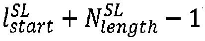
- In slot l, all symbols (for example, for NCP, symbol 0, symbol 1, ..., and symbol 13; as another example, for ECP, symbol 0, symbol 1, ..., and symbol 11) are configured to be uplink symbols.
- In this manner, according to Embodiment 1, provided in the present invention is a method, which effectively combines parameter values of TDD configuration in SL common control information, thereby achieving effective indication of the TDD configuration.
- Hereinafter,
FIG. 2 is used to illustrate user equipment that can perform the method performed by user equipment described in detail above in the present invention as a variant embodiment. -
FIG. 2 is a block diagram showing user equipment (UE) according to the present invention. - As shown in
FIG. 2 , user equipment (UE) 20 includes aprocessor 201 and amemory 202. Theprocessor 201 may include, for example, a microprocessor, a microcontroller, an embedded processor, and the like. The memory 220 may, for example, include a volatile memory (for example, a random access memory (RAM)), a hard disk drive (HDD), a non-volatile memory (for example, a flash memory), or other memories. Thememory 202 stores program instructions. The instructions, when run by theprocessor 201, may perform the method performed by user equipment as described above in detail in the present invention. - The methods and related equipment according to the present invention have been described above in combination with preferred embodiments. It should be understood by those skilled in the art that the methods shown above are only exemplary, and the above embodiments can be combined with one another as long as no contradiction arises. The methods of the present invention are not limited to the steps or sequences illustrated above. The network node and user equipment illustrated above may include more modules. For example, the network node and user equipment may further include modules that can be developed or will be developed in the future to be applied to a base station, an MME, or UE, and the like. Various identifiers shown above are only exemplary, and are not meant for limiting the present invention. The present invention is not limited to specific information elements serving as examples of these identifiers. A person skilled in the art could make various alterations and modifications according to the teachings of the illustrated embodiments. Those skilled in the art should understand that part of or all of the mathematical expressions, mathematical equations, or mathematical inequalities may be simplified (for example, incorporating constant terms, or interchanging two addition terms, or interchanging two multiplication terms, or the like) or transformed or rewritten to some extent. Mathematical expressions, mathematical equations, or mathematical inequalities before and after the simplification or transformation or rewriting may be considered to be equivalent to each other.
- It should be understood that the above-described embodiments of the present invention may be implemented by software, hardware, or a combination of software and hardware. For example, various components of the base station and user equipment in the above embodiments can be realized through multiple devices, and these devices include but are not limited to: an analog circuit device, a digital circuit device, a digital signal processing (DSP) circuit, a programmable processor, an application specific integrated circuit (ASIC), a field programmable gate array (FPGA), and a complex programmable logic device (CPLD), and the like.
In this application, the term "base station" may refer to a mobile communication data and control switching center having specific transmission power and a specific coverage area and including functions such as resource allocation and scheduling, data reception and transmission, and the like. "User equipment" may refer to a user mobile terminal, for example, including terminal devices that can communicate with a base station or a micro base station wirelessly, such as a mobile phone, a laptop computer, and the like. - In addition, the embodiments of the present invention disclosed herein may be implemented on a computer program product. More specifically, the computer program product is a product provided with a computer-readable medium having computer program logic encoded thereon. When executed on a computing device, the computer program logic provides related operations to implement the above technical solutions of the present invention. When executed on at least one processor of a computing system, the computer program logic enables the processor to execute the operations (methods) described in the embodiments of the present invention. Such an arrangement of the present invention is typically provided as software, a code, and/or other data structures that are configured or encoded on a computer-readable medium, such as an optical medium (e.g., a CD-ROM), a floppy disk or a hard disk, or, for example, firmware or other media of microcodes on one or more ROM or RAM or PROM chips, or downloadable software images, shared database and so on in one or more modules. Software or firmware or such configuration may be installed on a computing device such that one or more processors in the computing device perform the technical solutions described in the embodiments of the present invention.
- In addition, each functional module or each feature of the base station device and the terminal device used in each of the above embodiments may be implemented or executed by a circuit, which is usually one or more integrated circuits. Circuits designed to execute various functions described in this description may include general-purpose processors, digital signal processors (DSPs), application specific integrated circuits (ASICs) or general-purpose integrated circuits, field programmable gate arrays (FPGAs) or other programmable logic devices, discrete gates or transistor logic, or discrete hardware components, or any combination of the above. The general purpose processor may be a microprocessor, or the processor may be an existing processor, a controller, a microcontroller, or a state machine. The aforementioned general purpose processor or each circuit may be configured by a digital circuit or may be configured by a logic circuit. Furthermore, when advanced technology capable of replacing current integrated circuits emerges due to advances in semiconductor technology, the present invention can also use integrated circuits obtained using this advanced technology.
- While the present invention has been illustrated in combination with the preferred embodiments of the present invention, it will be understood by those skilled in the art that various modifications, substitutions, and alterations may be made to the present invention without departing from the spirit and scope of the present invention. Therefore, the present invention should not be limited by the above-described embodiments, but should be defined by the appended claims and their equivalents.
• Optionally, the "message related to SL" corresponds to (or is associated with) an SCS (e.g., corresponding SCS configuration is denoted as µSL ), e.g., an SCS of the SL carrier CSL, or an SCS of an SL BWP on the SL carrier CSL, or an SCS of an SL BWP used to transmit the "message related to SL", or an SCS of a resource pool used to transmit the "message related to SL", or an SCS of an S-SSB carrying the "message related to SL".
• Optionally, the "message related to SL" may contain one or a plurality of the following:
◆ TDD configuration information, indicated by, for example, a parameter sl-TDD-Config. Wherein,
∘ The "TDD configuration information" may contain one or a plurality of the following:
◇ number of patterns (e.g., the value thereof is denoted as Npatterns ). Wherein,
◇ Periodicity information (e.g., the value thereof is denoted as Iperiods ). Wherein,
➢ Optionally, the size of the "periodicity information" may be Y bits, where Y may be a predefined or pre-configured or a configured value. For example, Y = 4.
➢ Optionally, the "periodicity information" is used to indicate the period corresponding to the one pattern indicated by the "number of patterns" or the periods respectively corresponding to the two patterns indicated by the "number of patterns". For example, if the number of patterns indicated by the "number of patterns" is 1, then the "periodicity information" indicates the period (e.g., denoted as Q) of pattern 1. As another example, if the number of patterns indicated by the "number of patterns" is 2, then the "periodicity information" indicates the period (e.g., denoted as Q) of pattern 1 and the period (e.g., denoted as Q2) of pattern 2, which are, for example, denoted as <Q, Q2> by combining Q and Q2. Wherein,
✧ Optionally, the period Q is in units of milliseconds.
✧ Optionally, the period Q2 is in units of milliseconds. For example, if the number of patterns indicated by the "number of patterns" is 1, then the set of the values of Iperiods may be {0, 1, 2, 3, 4, 5, 6, 7, 8} or {1, 2, 3, 4, 5, 6, 7, 8, 9}, or another subset (e.g. a subset of the size of 9) of the set {0, 1, 2, 3, 4, 5, 6, 7, 8, 9, 10, 11, 12, 13, 14, 15}. Correspondingly, the set of the values of Q may be {0.5, 0.625, 1, 1.25, 2, 2.5, 4, 5, 10}. The set of values of Iperiods may be mapped to the set of values of Q in a one-to-one correspondence in any order. For example, mapping is performed in a method shown in the following table.
| Iperiods | Q |
| 0 | 0.5 |
| 1 | 0.625 |
| 2 | 1 |
| 3 | 1.25 |
| 4 | 2 |
| 5 | 2.5 |
| 6 | 4 |
| 7 | 5 |
| 8 | 10 |
| Iperiods | <Q, Q2> |
| 0 | <0.5, 0.5> |
| 1 | <0.625, 0.625> |
| 2 | <1, 1> |
| 3 | <0.5, 2> |
| 4 | <1.25, 1.25> |
| 5 | <2, 0.5> |
| 6 | <1, 3> |
| 7 | <2, 2> |
| 8 | <3, 1> |
| 9 | <1, 4> |
| 10 | <2, 3> |
| 11 | <2.5, 2.5> |
| 12 | <3, 2> |
| 13 | <4, 1> |
| 14 | <5, 5> |
| 15 | <10, 10> |
◇ UL slot information (e.g., the value thereof is denoted as IUL ).
◆ "In-coverage" indication, indicated by, for example, a parameter inCoverage. Wherein,
◆ A direct frame number, indicated by, for example, a parameter directFrameNumber. The direct frame number may indicate a frame number of a corresponding S-SSB (e.g., the S-SSB carrying the "message related to SL"). Wherein,
◆ A slot index (or referred to as a slot number), indicated by, for example, a parameter slotIndex. The slot index may indicate an index (or referred to as a number) of a slot in which the corresponding S-SSB (e.g., the S-SSB carrying the "message related to SL") is located, e.g., the slot number within a frame. Wherein,
◆ Reserved bits, indicated by, for example, a parameter reservedBits. Wherein,
• Optionally, the "setting content of a message related to SL" includes: for each i, performing either of the two in the following (e.g., determining either of the two in the following in a predefined method):
• Optionally, each "SL setup operation i" may include one or a plurality of the following:
o The value Npatterns of the "number of patterns" is set to 0.
∘ The value Npatterns of the "number of patterns" is set to 1.
∘ The value Npatterns of the "number of patterns" is set to any value in {0, 1}.
∘ The value Npatterns of the "number of patterns" is set to the maximum value among all valid values (i.e., excluding the reserved or undefined value) thereof.
∘ The value Npatterns of the "number of patterns" is set to the minimum value among all valid values (i.e., excluding the reserved or undefined value) thereof.
∘ The value Iperiods of the "periodicity information" is set to the value of Iperiods in the row corresponding to Q = P in the "mapping relationship of the set of the values of Iperiods to the set of the values of Q" (e.g., Table 1).
∘ The value Iperiods of the "periodicity information" is set to the value of Iperiods in the row corresponding to <Q, Q2> = <P, P2> in the "mapping relationship of the set of the values of Iperiods to the set of the values of <Q, Q2>" (e.g., Table 2).
∘ The value Iperiods of the "periodicity information" is set to 0.
∘ The value Iperiods of the "periodicity information" is set to 1.
∘ The value Iperiods of the "periodicity information" is set to 2.
∘ The value Iperiods of the "periodicity information" is set to 3.
∘ The value Iperiods of the "periodicity information" is set to 4.
∘ The value Iperiods of the "periodicity information" is set to 5.
∘ The value Iperiods of the "periodicity information" is set to 6.
∘ The value Iperiods of the "periodicity information" is set to 7.
∘ The value Iperiods of the "periodicity information" is set to 8.
∘ The value Iperiods of the "periodicity information" is set to 9.
∘ The value Iperiods of the "periodicity information" is set to 10.
∘ The value Iperiods of the "periodicity information" is set to 11.
∘ The value Iperiods of the "periodicity information" is set to 12.
∘ The value Iperiods of the "periodicity information" is set to 13.
∘ The value Iperiods of the "periodicity information" is set to 14.
∘ The value Iperiods of the "periodicity information" is set to 15.
∘ The value Iperiods of the "periodicity information" is set to any value in {0, 1, ..., 15}.
∘ The value Iperiods of the "periodicity information" is set to any value in {0, 1}.
∘ The value Iperiods of the "periodicity information" is set to any value in {0, 1, 2}.
∘ The value Iperiods of the "periodicity information" is set to any value in {0, 1, 2, 3}.
∘ The value Iperiods of the "periodicity information" is set to any value in {0, 1, ..., 4}.
∘ The value Iperiods of the "periodicity information" is set to any value in {0, 1, ..., 5}.
∘ The value Iperiods of the "periodicity information" is set to any value in {0, 1, ..., 6}.
∘ The value Iperiods of the "periodicity information" is set to any value in {0, 1, ..., 7}.
∘ The value Iperiods of the "periodicity information" is set to any value in {0, 1, ..., 8}.
∘ The value Iperiods of the "periodicity information" is set to any value in {7, 8, ..., 15}.
∘ The value Iperiods of the "periodicity information" is set to any value in {8, 9, ..., 15}.
∘ The value Iperiods of the "periodicity information" is set to any value in {9, 10, ..., 15}.
∘ The value Iperiods of the "periodicity information" is set to any value in {10, 11, ..., 15}.
∘ The value Iperiods of the "periodicity information" is set to any value in {11, 12, ..., 15}.
∘ The value Iperiods of the "periodicity information" is set to any value in {12, 13, 14, 15}.
∘ The value Iperiods of the "periodicity information" is set to any value in {13, 14, 15}.
∘ The value Iperiods of the "periodicity information" is set to any value in {14, 15}.
∘ The value Iperiods of the "periodicity information" is set to the maximum value among all valid values (i.e., excluding the reserved or undefined value) thereof.
∘ The value Iperiods of the "periodicity information" is set to the minimum value among all valid values (i.e., excluding the reserved or undefined value) thereof.
∘ The value IUL of the "UL slot information" is set to one of the following:
o The value IUL of the "UL slot information" is adjusted. For example, IUL is set to IUL /N. Wherein,
◇ Optionally, only when pattern2 in the parameter tdd-UL-DL-ConfigurationCommon is configured, the value IUL of the "UL slot information" is adjusted.
◇ Optionally, only when a UL slot information adjustment condition is satisfied, the value IUL of the "UL slot information" is adjusted. For example, the value IUL of the "UL slot information" is adjusted according to the value N defined in Table 3.
◇ Optionally, in the case that the value N is not defined, the value IUL of the "UL slot information" is not adjusted.
◇ Optionally, in the case that the value N is not defined, the value IUL of the "UL slot information" is adjusted according to N = 1.
| <Q, Q2> | µSL | ||
| 1 | 2 | 3 | |
| <1, 3> | 2 | ||
| <2, 2> | 4 | ||
| <3, 1> | 2 | ||
| <1, 4> | 4 | ||
| <2, 3> | 4 | ||
| <2.5, 2.5> | 4 | ||
| <3, 2> | 4 | ||
| <4, 1> | 4 | ||
| <5, 5> | 4 | 16 | |
| <10, 10> | 4 | 16 | 64 |
∘ The value IUL of the "UL slot information" is set to a predefined or pre-configured or configured value in the set {0, 1, ..., 127}, e.g., 0, 1, 2, 3, 4, 5, 6, 7, 8, 9, 118, 119, 120, 121, 122, 123, 124, 125, 126, or 127.
∘ The value IUL of the "UL slot information" is set to any value in the set {0, 1, ..., 127}.
∘ The value IUL of the "UL slot information" is set to any value in a predefined or pre-configured or configured subset of the set {0, 1, ..., 127}. The subset may be any subset of the set {0, 1, ..., 127}.
∘ The value IUL of the "UL slot information" is set to the maximum value among all valid values (i.e., excluding the reserved or undefined value) thereof.
∘ The value IUL of the "UL slot information" is set to the minimum value among all valid values (i.e., excluding the reserved or undefined value) thereof.
∘ The value IUL of the "UL slot information" is set to a value corresponding to the maximum number of UL slots. For example, if the "number of patterns" indicates 1 pattern, then the value IUL of the "UL slot information" is set to the value of IUL corresponding to the case that the "UL slot information" indicates that the number D of UL slots in the period of pattern 1 is the maximum value. As another example, if the "number of patterns" indicates 2 patterns, then the value of the "UL slot information" is set to the value of IUL corresponding to the case that both D and D2 in the combination <D, D2> of the number of UL slots in the period of pattern 1 and the number of UL slots in the period of pattern 2 indicated by the "UL slot information" are both the maximum values.
∘ The value IUL of the "UL slot information" is set to the value corresponding to the case that all slots in indicated (one or two) periods are UL slots. Optionally, in this case, the value of IUL satisfying the condition concerns one or a plurality of µSL, Npatterns, or Iperiods.
For example, the "setting content of a message related to SL" includes: if a TDD condition is not satisfied (or no applicable TDD configuration is present, for example, the SIB1 message does not contain the parameter tdd-UL-DL-ConfigurationCommon), then: setting the value Npatterns of the "number of patterns" to 0, setting the value Iperiods of the "periodicity information" to 15, and setting the value IUL of the "UL slot information" to 127.
Claims (2)
- A method performed by user equipment (UE), characterized by comprising:setting content of a message of 12 bits in a PSBCH of an S-SS/PSBCH block; andtransmitting the S-SS/PSBCH block,whereinone bit of the 12 bits is used to indicate whether pattern 1 is used or both of pattern 1 and pattern 2 are used for TDD configuration, andfor FDD, or for a spectrum supporting only a PC5 interface and not provided with the TDD configuration, the 12 bits are all set to '1'.
- User equipment, comprising:a processor; anda memory storing instructions,wherein the instructions, when run by the processor, perform the method according to claim 1.
Applications Claiming Priority (2)
| Application Number | Priority Date | Filing Date | Title |
|---|---|---|---|
| CN202010410583.0A CN113676299B (en) | 2020-05-14 | 2020-05-14 | User equipment and method for transmitting S-SS/PSBCH blocks |
| PCT/CN2021/093309 WO2021228136A1 (en) | 2020-05-14 | 2021-05-12 | Method executed by user equipment, and user equipment |
Publications (3)
| Publication Number | Publication Date |
|---|---|
| EP4152856A1 true EP4152856A1 (en) | 2023-03-22 |
| EP4152856A4 EP4152856A4 (en) | 2024-05-29 |
| EP4152856B1 EP4152856B1 (en) | 2025-12-10 |
Family
ID=78526014
Family Applications (1)
| Application Number | Title | Priority Date | Filing Date |
|---|---|---|---|
| EP21803950.1A Active EP4152856B1 (en) | 2020-05-14 | 2021-05-12 | Method performed by user equipment, and user equipment |
Country Status (4)
| Country | Link |
|---|---|
| US (1) | US12432756B2 (en) |
| EP (1) | EP4152856B1 (en) |
| CN (1) | CN113676299B (en) |
| WO (1) | WO2021228136A1 (en) |
Families Citing this family (2)
| Publication number | Priority date | Publication date | Assignee | Title |
|---|---|---|---|---|
| EP3952564B1 (en) * | 2019-05-15 | 2024-04-03 | Guangdong Oppo Mobile Telecommunications Corp., Ltd. | Communication method in d2d system, terminal device, and d2d system |
| US20240072986A1 (en) * | 2022-08-30 | 2024-02-29 | Qualcomm Incorporated | Configuring duplexing pattern |
Family Cites Families (11)
| Publication number | Priority date | Publication date | Assignee | Title |
|---|---|---|---|---|
| CN105515721B (en) * | 2014-09-25 | 2020-01-07 | 中兴通讯股份有限公司 | Bit number indication method and device |
| US20170273135A1 (en) * | 2015-10-15 | 2017-09-21 | Telefonaktiebolaget Lm Ericsson (Publ) | Methods of managing long inactivity periods in non-full duplex operation |
| WO2018084524A1 (en) * | 2016-11-02 | 2018-05-11 | 엘지전자(주) | Method for performing sidelink transmission in wireless communication system and apparatus therefor |
| WO2020032704A1 (en) * | 2018-08-10 | 2020-02-13 | 주식회사 아이티엘 | Method and device for performing synchronization procedure for nr v2x system |
| CN110958099A (en) * | 2018-09-27 | 2020-04-03 | 夏普株式会社 | Method performed by user equipment and user equipment |
| KR20200050432A (en) * | 2018-11-01 | 2020-05-11 | 한양대학교 산학협력단 | Methods for performing v2x communication and appratuses thereof |
| CN111130729A (en) * | 2018-11-01 | 2020-05-08 | 夏普株式会社 | Method performed by user equipment and user equipment |
| WO2020091500A1 (en) * | 2018-11-02 | 2020-05-07 | 엘지전자 주식회사 | Method for transmitting and receiving synchronization signal in device to device wireless communication, and apparatus for same |
| WO2020180098A1 (en) * | 2019-03-04 | 2020-09-10 | 엘지전자 주식회사 | Information on sidelink resource |
| WO2021162356A1 (en) * | 2020-02-12 | 2021-08-19 | 엘지전자 주식회사 | Method and device for transmitting information related to sl slot in nr v2x |
| EP4135450A4 (en) * | 2020-04-09 | 2024-05-01 | LG Electronics, Inc. | Method and device for transmitting information related to slot pattern in nr v2x |
-
2020
- 2020-05-14 CN CN202010410583.0A patent/CN113676299B/en active Active
-
2021
- 2021-05-12 EP EP21803950.1A patent/EP4152856B1/en active Active
- 2021-05-12 WO PCT/CN2021/093309 patent/WO2021228136A1/en not_active Ceased
- 2021-05-12 US US17/923,983 patent/US12432756B2/en active Active
Also Published As
| Publication number | Publication date |
|---|---|
| WO2021228136A1 (en) | 2021-11-18 |
| US20230189302A1 (en) | 2023-06-15 |
| US12432756B2 (en) | 2025-09-30 |
| EP4152856A4 (en) | 2024-05-29 |
| CN113676299A (en) | 2021-11-19 |
| CN113676299B (en) | 2025-10-14 |
| EP4152856B1 (en) | 2025-12-10 |
Similar Documents
| Publication | Publication Date | Title |
|---|---|---|
| US12255852B2 (en) | Method performed by user equipment, and user equipment | |
| US12574182B2 (en) | Method performed by user equipment, and user equipment | |
| US12484029B2 (en) | Method performed by user equipment, and user equipment | |
| US12200687B2 (en) | Method performed by user equipment, and user equipment | |
| EP4135420A1 (en) | Method executed by user equipment and user equipment | |
| US20220006677A1 (en) | Method performed by user equipment, and user equipment | |
| US12238738B2 (en) | Method performed by a user equipment. and user equipment for a downlink control information size alignment | |
| EP4152856B1 (en) | Method performed by user equipment, and user equipment | |
| WO2022028274A1 (en) | Method executed by user equipment, and user equipment | |
| WO2022068685A1 (en) | Method executed by user equipment, and user equipment | |
| WO2022028328A1 (en) | Method executed by user equipment and user equipment | |
| US12446095B2 (en) | Method performed by user equipment, user equipment, and base station to determine HARQ-ACK codebooks for sidelink and downlink transmissions | |
| WO2021197210A1 (en) | Method executed by user equipment, and user equipment | |
| US20230039007A1 (en) | Method performed by user equipment, and user equipment | |
| CN114698129A (en) | Method performed by user equipment and user equipment | |
| CN113726489A (en) | Method performed by user equipment and user equipment | |
| US20230379121A1 (en) | Method performed by user equipment, and user equipment | |
| WO2021063337A1 (en) | Method executed by user equipment, and user equipment |
Legal Events
| Date | Code | Title | Description |
|---|---|---|---|
| STAA | Information on the status of an ep patent application or granted ep patent |
Free format text: STATUS: THE INTERNATIONAL PUBLICATION HAS BEEN MADE |
|
| PUAI | Public reference made under article 153(3) epc to a published international application that has entered the european phase |
Free format text: ORIGINAL CODE: 0009012 |
|
| STAA | Information on the status of an ep patent application or granted ep patent |
Free format text: STATUS: REQUEST FOR EXAMINATION WAS MADE |
|
| 17P | Request for examination filed |
Effective date: 20221117 |
|
| AK | Designated contracting states |
Kind code of ref document: A1 Designated state(s): AL AT BE BG CH CY CZ DE DK EE ES FI FR GB GR HR HU IE IS IT LI LT LU LV MC MK MT NL NO PL PT RO RS SE SI SK SM TR |
|
| DAV | Request for validation of the european patent (deleted) | ||
| DAX | Request for extension of the european patent (deleted) | ||
| REG | Reference to a national code |
Ref country code: DE Ref legal event code: R079 Free format text: PREVIOUS MAIN CLASS: H04W0072040000 Ipc: H04L0005000000 Ref document number: 602021044229 Country of ref document: DE |
|
| A4 | Supplementary search report drawn up and despatched |
Effective date: 20240425 |
|
| RIC1 | Information provided on ipc code assigned before grant |
Ipc: H04W 92/18 20090101ALN20240419BHEP Ipc: H04W 72/40 20230101ALN20240419BHEP Ipc: H04W 72/23 20230101ALI20240419BHEP Ipc: H04W 48/12 20090101ALI20240419BHEP Ipc: H04L 5/00 20060101AFI20240419BHEP |
|
| GRAP | Despatch of communication of intention to grant a patent |
Free format text: ORIGINAL CODE: EPIDOSNIGR1 |
|
| STAA | Information on the status of an ep patent application or granted ep patent |
Free format text: STATUS: GRANT OF PATENT IS INTENDED |
|
| RIC1 | Information provided on ipc code assigned before grant |
Ipc: H04L 5/00 20060101AFI20250717BHEP Ipc: H04W 48/12 20090101ALI20250717BHEP Ipc: H04W 72/23 20230101ALI20250717BHEP Ipc: H04W 72/40 20230101ALN20250717BHEP Ipc: H04W 92/18 20090101ALN20250717BHEP |
|
| INTG | Intention to grant announced |
Effective date: 20250728 |
|
| GRAS | Grant fee paid |
Free format text: ORIGINAL CODE: EPIDOSNIGR3 |
|
| GRAA | (expected) grant |
Free format text: ORIGINAL CODE: 0009210 |
|
| STAA | Information on the status of an ep patent application or granted ep patent |
Free format text: STATUS: THE PATENT HAS BEEN GRANTED |
|
| AK | Designated contracting states |
Kind code of ref document: B1 Designated state(s): AL AT BE BG CH CY CZ DE DK EE ES FI FR GB GR HR HU IE IS IT LI LT LU LV MC MK MT NL NO PL PT RO RS SE SI SK SM TR |
|
| REG | Reference to a national code |
Ref country code: CH Ref legal event code: F10 Free format text: ST27 STATUS EVENT CODE: U-0-0-F10-F00 (AS PROVIDED BY THE NATIONAL OFFICE) Effective date: 20251210 Ref country code: GB Ref legal event code: FG4D |
|
| REG | Reference to a national code |
Ref country code: DE Ref legal event code: R096 Ref document number: 602021044229 Country of ref document: DE |
|
| REG | Reference to a national code |
Ref country code: IE Ref legal event code: FG4D |
|
| PGFP | Annual fee paid to national office [announced via postgrant information from national office to epo] |
Ref country code: GB Payment date: 20260306 Year of fee payment: 6 |
|
| PG25 | Lapsed in a contracting state [announced via postgrant information from national office to epo] |
Ref country code: ES Free format text: LAPSE BECAUSE OF FAILURE TO SUBMIT A TRANSLATION OF THE DESCRIPTION OR TO PAY THE FEE WITHIN THE PRESCRIBED TIME-LIMIT Effective date: 20251210 |
|
| REG | Reference to a national code |
Ref country code: LT Ref legal event code: MG9D |
|
| PG25 | Lapsed in a contracting state [announced via postgrant information from national office to epo] |
Ref country code: NO Free format text: LAPSE BECAUSE OF FAILURE TO SUBMIT A TRANSLATION OF THE DESCRIPTION OR TO PAY THE FEE WITHIN THE PRESCRIBED TIME-LIMIT Effective date: 20260310 |
|
| PG25 | Lapsed in a contracting state [announced via postgrant information from national office to epo] |
Ref country code: FI Free format text: LAPSE BECAUSE OF FAILURE TO SUBMIT A TRANSLATION OF THE DESCRIPTION OR TO PAY THE FEE WITHIN THE PRESCRIBED TIME-LIMIT Effective date: 20251210 Ref country code: HR Free format text: LAPSE BECAUSE OF FAILURE TO SUBMIT A TRANSLATION OF THE DESCRIPTION OR TO PAY THE FEE WITHIN THE PRESCRIBED TIME-LIMIT Effective date: 20251210 |
|
| REG | Reference to a national code |
Ref country code: NL Ref legal event code: MP Effective date: 20251210 |
|
| PG25 | Lapsed in a contracting state [announced via postgrant information from national office to epo] |
Ref country code: RS Free format text: LAPSE BECAUSE OF FAILURE TO SUBMIT A TRANSLATION OF THE DESCRIPTION OR TO PAY THE FEE WITHIN THE PRESCRIBED TIME-LIMIT Effective date: 20260310 |
|
| PG25 | Lapsed in a contracting state [announced via postgrant information from national office to epo] |
Ref country code: LV Free format text: LAPSE BECAUSE OF FAILURE TO SUBMIT A TRANSLATION OF THE DESCRIPTION OR TO PAY THE FEE WITHIN THE PRESCRIBED TIME-LIMIT Effective date: 20251210 |
|
| PG25 | Lapsed in a contracting state [announced via postgrant information from national office to epo] |
Ref country code: BG Free format text: LAPSE BECAUSE OF FAILURE TO SUBMIT A TRANSLATION OF THE DESCRIPTION OR TO PAY THE FEE WITHIN THE PRESCRIBED TIME-LIMIT Effective date: 20251210 |