EP4152811A1 - Cache determining method and apparatus - Google Patents
Cache determining method and apparatus Download PDFInfo
- Publication number
- EP4152811A1 EP4152811A1 EP21805145.6A EP21805145A EP4152811A1 EP 4152811 A1 EP4152811 A1 EP 4152811A1 EP 21805145 A EP21805145 A EP 21805145A EP 4152811 A1 EP4152811 A1 EP 4152811A1
- Authority
- EP
- European Patent Office
- Prior art keywords
- sidelink
- data rate
- round trip
- trip time
- buffer size
- Prior art date
- Legal status (The legal status is an assumption and is not a legal conclusion. Google has not performed a legal analysis and makes no representation as to the accuracy of the status listed.)
- Pending
Links
- 238000000034 method Methods 0.000 title claims abstract description 103
- 238000004891 communication Methods 0.000 claims abstract description 111
- 239000013256 coordination polymer Substances 0.000 claims description 85
- 230000005540 biological transmission Effects 0.000 claims description 58
- 238000012545 processing Methods 0.000 claims description 41
- 238000013507 mapping Methods 0.000 claims description 30
- 230000001413 cellular effect Effects 0.000 claims description 29
- 230000008569 process Effects 0.000 claims description 18
- 238000004590 computer program Methods 0.000 claims description 12
- 125000004122 cyclic group Chemical group 0.000 claims description 10
- 238000013461 design Methods 0.000 description 82
- 235000019580 granularity Nutrition 0.000 description 20
- 230000006870 function Effects 0.000 description 18
- 238000010586 diagram Methods 0.000 description 15
- 238000005516 engineering process Methods 0.000 description 5
- 230000009286 beneficial effect Effects 0.000 description 4
- 230000000694 effects Effects 0.000 description 4
- 238000004364 calculation method Methods 0.000 description 3
- 239000003795 chemical substances by application Substances 0.000 description 2
- 230000000977 initiatory effect Effects 0.000 description 2
- 230000007774 longterm Effects 0.000 description 2
- 238000012986 modification Methods 0.000 description 2
- 230000004048 modification Effects 0.000 description 2
- 230000002776 aggregation Effects 0.000 description 1
- 238000004220 aggregation Methods 0.000 description 1
- 230000008901 benefit Effects 0.000 description 1
- 239000000969 carrier Substances 0.000 description 1
- 238000013500 data storage Methods 0.000 description 1
- 238000011161 development Methods 0.000 description 1
- 230000007246 mechanism Effects 0.000 description 1
- 230000003287 optical effect Effects 0.000 description 1
- 239000013307 optical fiber Substances 0.000 description 1
- 238000013468 resource allocation Methods 0.000 description 1
- 239000004065 semiconductor Substances 0.000 description 1
Images


Classifications
-
- H—ELECTRICITY
- H04—ELECTRIC COMMUNICATION TECHNIQUE
- H04W—WIRELESS COMMUNICATION NETWORKS
- H04W28/00—Network traffic management; Network resource management
- H04W28/16—Central resource management; Negotiation of resources or communication parameters, e.g. negotiating bandwidth or QoS [Quality of Service]
- H04W28/18—Negotiating wireless communication parameters
- H04W28/22—Negotiating communication rate
-
- H—ELECTRICITY
- H04—ELECTRIC COMMUNICATION TECHNIQUE
- H04L—TRANSMISSION OF DIGITAL INFORMATION, e.g. TELEGRAPHIC COMMUNICATION
- H04L47/00—Traffic control in data switching networks
- H04L47/50—Queue scheduling
- H04L47/52—Queue scheduling by attributing bandwidth to queues
-
- H—ELECTRICITY
- H04—ELECTRIC COMMUNICATION TECHNIQUE
- H04L—TRANSMISSION OF DIGITAL INFORMATION, e.g. TELEGRAPHIC COMMUNICATION
- H04L1/00—Arrangements for detecting or preventing errors in the information received
- H04L1/0001—Systems modifying transmission characteristics according to link quality, e.g. power backoff
- H04L1/0002—Systems modifying transmission characteristics according to link quality, e.g. power backoff by adapting the transmission rate
-
- H—ELECTRICITY
- H04—ELECTRIC COMMUNICATION TECHNIQUE
- H04B—TRANSMISSION
- H04B7/00—Radio transmission systems, i.e. using radiation field
- H04B7/14—Relay systems
- H04B7/15—Active relay systems
- H04B7/185—Space-based or airborne stations; Stations for satellite systems
- H04B7/1851—Systems using a satellite or space-based relay
-
- H—ELECTRICITY
- H04—ELECTRIC COMMUNICATION TECHNIQUE
- H04B—TRANSMISSION
- H04B7/00—Radio transmission systems, i.e. using radiation field
- H04B7/14—Relay systems
- H04B7/15—Active relay systems
- H04B7/185—Space-based or airborne stations; Stations for satellite systems
- H04B7/1853—Satellite systems for providing telephony service to a mobile station, i.e. mobile satellite service
- H04B7/18558—Arrangements for managing communications, i.e. for setting up, maintaining or releasing a call between stations
-
- H—ELECTRICITY
- H04—ELECTRIC COMMUNICATION TECHNIQUE
- H04L—TRANSMISSION OF DIGITAL INFORMATION, e.g. TELEGRAPHIC COMMUNICATION
- H04L47/00—Traffic control in data switching networks
- H04L47/10—Flow control; Congestion control
- H04L47/30—Flow control; Congestion control in combination with information about buffer occupancy at either end or at transit nodes
-
- H—ELECTRICITY
- H04—ELECTRIC COMMUNICATION TECHNIQUE
- H04L—TRANSMISSION OF DIGITAL INFORMATION, e.g. TELEGRAPHIC COMMUNICATION
- H04L47/00—Traffic control in data switching networks
- H04L47/50—Queue scheduling
- H04L47/62—Queue scheduling characterised by scheduling criteria
- H04L47/625—Queue scheduling characterised by scheduling criteria for service slots or service orders
- H04L47/626—Queue scheduling characterised by scheduling criteria for service slots or service orders channel conditions
-
- H—ELECTRICITY
- H04—ELECTRIC COMMUNICATION TECHNIQUE
- H04W—WIRELESS COMMUNICATION NETWORKS
- H04W28/00—Network traffic management; Network resource management
- H04W28/02—Traffic management, e.g. flow control or congestion control
- H04W28/0268—Traffic management, e.g. flow control or congestion control using specific QoS parameters for wireless networks, e.g. QoS class identifier [QCI] or guaranteed bit rate [GBR]
-
- H—ELECTRICITY
- H04—ELECTRIC COMMUNICATION TECHNIQUE
- H04W—WIRELESS COMMUNICATION NETWORKS
- H04W28/00—Network traffic management; Network resource management
- H04W28/02—Traffic management, e.g. flow control or congestion control
- H04W28/0278—Traffic management, e.g. flow control or congestion control using buffer status reports
-
- H—ELECTRICITY
- H04—ELECTRIC COMMUNICATION TECHNIQUE
- H04W—WIRELESS COMMUNICATION NETWORKS
- H04W28/00—Network traffic management; Network resource management
- H04W28/16—Central resource management; Negotiation of resources or communication parameters, e.g. negotiating bandwidth or QoS [Quality of Service]
-
- H—ELECTRICITY
- H04—ELECTRIC COMMUNICATION TECHNIQUE
- H04L—TRANSMISSION OF DIGITAL INFORMATION, e.g. TELEGRAPHIC COMMUNICATION
- H04L1/00—Arrangements for detecting or preventing errors in the information received
- H04L1/0001—Systems modifying transmission characteristics according to link quality, e.g. power backoff
- H04L1/0002—Systems modifying transmission characteristics according to link quality, e.g. power backoff by adapting the transmission rate
- H04L1/0003—Systems modifying transmission characteristics according to link quality, e.g. power backoff by adapting the transmission rate by switching between different modulation schemes
Definitions
- This application relates to the field of communication technologies, and in particular, to a buffer determining method and apparatus.
- the size of the layer 2 buffer may be understood as a sum of quantities of bytes (bytes) that can be stored by user equipment (user equipment, UE) in a radio link control (radio link control, RLC) transmitting window, an RLC receiving and reordering window, and a packet data convergence protocol (packet data convergence protocol, PDCP) reordering window on all radio bearers.
- RLC radio link control
- PDCP packet data convergence protocol
- long term evolution long term evolution
- D2D device to device
- Sidelink Communication Sidelink Communication
- V2X vehicle-to-everything
- This application provides a buffer determining method and apparatus, to resolve a problem of how a terminal device on a sidelink calculates a buffer size.
- an embodiment of this application provides a buffer determining method.
- the method includes: A terminal device determines a sidelink data rate, and determines a buffer size based on the sidelink data rate.
- the terminal device may determine the buffer size based on the sidelink data rate, to implement calculation of a layer 2 buffer of UE in sidelink communication, for example, V2X sidelink communication, new radio (new radio, NR) sidelink communication, and LTE sidelink communication. Therefore, reference can be provided for the terminal device to determine the buffer size, thereby further facilitating implementation performed by the terminal device.
- the terminal device determines the buffer size based on the sidelink data rate
- the terminal device determines the buffer size based on the sidelink data rate and a sidelink round trip time.
- the terminal device can relatively accurately calculate the buffer size, to provide reference for the terminal device to determine the buffer size, thereby further facilitating implementation performed by the terminal device.
- the sidelink data rate includes a sidelink transmit data rate and/or a sidelink receive data rate.
- the terminal device may calculate the buffer size based on the sidelink transmit data rate, or based on the sidelink receive data rate, or based on the sidelink transmit data rate and the sidelink receive data rate.
- the sidelink data rate is a maximum value in the sidelink transmit data rate and the sidelink receive data rate.
- the terminal device may calculate the buffer size based on the maximum value in the sidelink transmit data rate and the sidelink receive data rate. Because the sidelink transmit data rate may be different from the sidelink receive rate, a larger value is selected to determine a buffer, so that the buffer size can be more accurately calculated. In this way, the determined buffer size can meet a sidelink communication requirement of the terminal device, thereby improving communication quality of the sidelink communication.
- the sidelink transmit data rate is determined based on one or more of the following parameters: a quantity of transmit layers, a transmit modulation order number, and an overhead.
- the quantity of transmit layers is a maximum quantity of sidelink transmit layers supported by the terminal device.
- the transmit modulation order number is a maximum modulation order number supported by the terminal device for sidelink transmission.
- the overhead is a parameter value greater than 0 and not greater than 1.
- the terminal device can effectively determine the sidelink transmit data rate based on a sidelink communication capability, which is very beneficial to indicate an implementation operation performed by the terminal device.
- SLTXDataRate is the sidelink transmit data rate
- V Layers is the quantity of transmit layers
- Q m is the transmit modulation order number
- f is an adjustment factor
- R max is a maximum target bit rate
- T S ⁇ is an average symbol length in a slot
- N PRB BW is a maximum quantity of allocated resource blocks in a bandwidth
- OH is the overhead.
- the sidelink receive data rate is determined based on one or more of the following parameters: a quantity of receive layers, a receive modulation order number, and an overhead.
- the quantity of receive layers is a maximum quantity of sidelink receive layers supported by the terminal device.
- the receive modulation order number is a maximum modulation order number supported by the terminal device for sidelink reception.
- the overhead is a parameter value greater than 0 and not greater than 1.
- the terminal device can effectively determine the sidelink receive data rate based on a sidelink communication capability, which is very beneficial to indicate an implementation operation performed by the terminal device.
- SLRXDataRate is the sidelink receive data rate
- V Layers is the quantity of receive layers
- Q m is the receive modulation order number
- f is an adjustment factor
- R max is a maximum target bit rate
- T S ⁇ is an average symbol length in a slot
- N PRB BW is a maximum quantity of allocated resource blocks in a bandwidth
- OH is the overhead.
- the overhead has at least one of the following correspondences: a correspondence between the overhead and a physical sidelink feedback channel (physical sidelink feedback channel, PSFCH) resource period, a correspondence between the overhead and a PSFCH, a correspondence between the overhead and a cyclic prefix (cyclic prefix, CP) type, and a correspondence between the overhead and a frequency range.
- PSFCH physical sidelink feedback channel
- CP cyclic prefix
- different overhead values may be used in different application scenarios, to improve accuracy of calculating the buffer size.
- flexibility of determining a buffer by the terminal device can be further improved, and unnecessary costs and overheads can be avoided, to achieve a purpose of reducing the costs.
- the correspondence between the overhead and the PSFCH resource period may be as follows: If the PSFCH resource period is 0, the OH may be 0.28.
- the OH may be 0.49.
- the OH may be 0.38.
- the OH may be 0.33.
- a correspondence between the overhead and each of the PSFCH resource period and the CP type may be as follows:
- the OH may be 0.28.
- the OH may be 0.49.
- the OH may be 0.38.
- the OH may be 0.33.
- the OH may be 0.32.
- the OH may be 0.57.
- the OH may be 0.45.
- the OH may be 0.39.
- the correspondence between the overhead and the frequency range may be as follows: If the frequency range is FR1, the OH is 0.277. If the frequency range is FR2, the OH is 0.278.
- the correspondence between the overhead and the frequency range may be as follows: If the frequency range is FR1, the OH is 0.323. If the frequency range is FR2, the OH is 0.324.
- a correspondence between the overhead and each of the PSFCH resource period, the frequency range, and the CP type may be as follows: If the frequency range is FR1, the CP type is an NCP, and the PSFCH resource period is 0, the overhead is 0.2771.
- the frequency range is FR1
- the CP type is an NCP
- the PSFCH resource period is 1
- the overhead is 0.4914.
- the frequency range is FR1
- the CP type is an NCP
- the PSFCH resource period is 2
- the overhead is 0.3843.
- the frequency range is FR1
- the CP type is an NCP
- the PSFCH resource period is 4, the overhead is 0.3307.
- the frequency range is FR1
- the CP type is an ECP
- the PSFCH resource period is 0, the overhead is 0.3233.
- the frequency range is FR1
- the CP type is an ECP
- the PSFCH resource period is 1
- the overhead is 0.5733.
- the frequency range is FR1
- the CP type is an ECP
- the PSFCH resource period is 2
- the overhead is 0.4483.
- the frequency range is FR1
- the CP type is an ECP
- the PSFCH resource period is 4, the overhead is 0.3858.
- the frequency range is FR2
- the CP type is an NCP
- the PSFCH resource period is 0, the overhead is 0.2779.
- the frequency range is FR2
- the CP type is an NCP
- the PSFCH resource period is 1, the overhead is 0.4921.
- the frequency range is FR2
- the CP type is an NCP
- the PSFCH resource period is 2
- the overhead is 0.3850.
- the frequency range is FR2
- the CP type is an NCP
- the PSFCH resource period is 4, the overhead is 0.3314.
- the frequency range is FR2
- the CP type is an ECP
- the PSFCH resource period is 0, the overhead is 0.3242.
- the frequency range is FR2
- the CP type is an ECP
- the PSFCH resource period is 1, the overhead is 0.5742.
- the frequency range is FR2
- the CP type is an ECP
- the PSFCH resource period is 2
- the overhead is 0.4492.
- the frequency range is FR2
- the CP type is an ECP
- the PSFCH resource period is 4, the overhead is 0.3867.
- Buffer Size is the buffer size
- SLTXDataRate is the sidelink transmit data rate
- SLRXDataRate is the sidelink receive data rate
- SL RTT is the sidelink round trip time
- Buffer Size is the buffer size
- SLDataRate is the maximum value in the sidelink transmit data rate and the sidelink receive data rate, or SLDataRate is the sidelink receive data rate, or SLDataRate is the sidelink transmit data rate
- SL RTT is the sidelink round trip time
- the sidelink round trip time is determined based on a first list.
- the first list includes a round trip time corresponding to subcarrier spacing of at least one sidelink frequency band.
- the sidelink round trip time is a sum of a time length of RLC polling and n times a maximum value of a hybrid automatic repeat request (hybrid automatic repeat request, HARQ) round trip time, where n is an integer greater than 0; or the sidelink round trip time is a sum of a time length of RLC polling and n times a minimum value of a HARQ round trip time, where n is an integer greater than 0; or the sidelink round trip time is an average value of a first value and a second value, where the first value is a sum of a time length of RLC polling and n times a maximum value of a HARQ round trip time, the second value is a sum of the time length of the RLC polling and n times a minimum value of the HARQ round trip time, and n is an integer greater than 0.
- HARQ hybrid automatic repeat request
- the first list may include the following: If the SCS is 15 kHz, the sidelink round trip time is 50 ms.
- the sidelink round trip time is 40 ms.
- the sidelink round trip time is 30 ms.
- the sidelink round trip time is 20 ms.
- the first list may alternatively include the following:
- the sidelink round trip time is 187 ms.
- the sidelink round trip time is 94 ms.
- the sidelink round trip time is 47 ms.
- the sidelink round trip time is 23 ms.
- the first list may alternatively include the following: If the SCS is 15 kHz, the sidelink round trip time is 37 ms.
- the sidelink round trip time is 19 ms.
- the sidelink round trip time is 9 ms.
- the sidelink round trip time is 5 ms.
- the first list may alternatively include the following:
- the sidelink round trip time is 112 ms.
- the sidelink round trip time is 56 ms.
- the sidelink round trip time is 28 ms.
- the sidelink round trip time is 14 ms.
- the first list may alternatively include the following: If the SCS is 15 kHz, the sidelink round trip time is 186 ms.
- the sidelink round trip time is 93 ms.
- the sidelink round trip time is 47 ms.
- the sidelink round trip time is 23 ms.
- the first list may alternatively include the following:
- the sidelink round trip time is 6 ms.
- the sidelink round trip time is 3 ms.
- the sidelink round trip time is 2 ms.
- the sidelink round trip time is 1 ms.
- the first list may alternatively include the following:
- the sidelink round trip time is 96 ms.
- the sidelink round trip time is 48 ms.
- the sidelink round trip time is 24 ms.
- the sidelink round trip time is 12 ms.
- the terminal device may further determine a downlink data rate and an uplink data rate.
- the terminal device may determine the buffer size based on the sidelink data rate, the downlink data rate, and the uplink data rate.
- the buffer size can be calculated in a case of an SL and Uu frequency band combination.
- the terminal device when the terminal device determines the buffer size based on the sidelink data rate, the downlink data rate, and the uplink data rate, the terminal device may determine the buffer size based on the sidelink data rate, the downlink data rate, the uplink data rate, the sidelink round trip time, and a cellular link round trip time.
- the cellular link round trip time is an RLC layer round trip time in cellular link communication.
- the terminal device can relatively accurately calculate the buffer size, to provide indicative reference for the terminal device to determine the buffer size.
- Buffer Size is the buffer size
- MaxULDataRate is the uplink data rate
- MaxDLDataRate is the downlink data rate
- RLC RTT is the cellular link round trip time
- SLTXDataRate is the sidelink transmit data rate
- SLRXDataRate is the sidelink receive data rate
- SL RTT is the sidelink round trip time
- Buffer Size is the buffer size
- MaxULDataRate is the uplink data rate
- MaxDLDataRate is the downlink data rate
- RLC RTT is the cellular link round trip time
- SLDataRate is the maximum value in the sidelink transmit data rate and the sidelink receive data rate
- SLDataRate is the sidelink receive data rate
- SLDataRate is the sidelink transmit data rate
- SL RTT is the sidelink round trip time
- the terminal device may further determine whether a physical sidelink shared channel (physical sidelink shared channel, PSSCH) meets a preset condition.
- the preset condition is related to the sidelink round trip time. If the PSSCH meets the preset condition, the terminal device processes the PSSCH. If the PSSCH does not meet the preset condition, the terminal device may not process the PSSCH.
- the preset condition may be as follows: V j L ⁇ T S ⁇ ⁇ SLDataRate
- the preset condition may be as follows: TBS L ⁇ T S ⁇ ⁇ SLDataRate
- an embodiment of this application provides a buffer determining method.
- the method includes: A terminal device determines a sidelink data rate, a downlink data rate, and an uplink data rate, and determines a buffer size based on the sidelink data rate, the downlink data rate, and the uplink data rate.
- This embodiment of this application is applicable to a scenario of a frequency band and/or a frequency band combination, especially for an SL and Uu frequency band combination.
- the terminal device may determine the buffer size based on the sidelink data rate, the uplink data rate, and the downlink data rate, to implement calculation of a layer 2 buffer of UE in sidelink communication, for example, V2X sidelink communication, NR sidelink communication, and LTE sidelink communication. Therefore, reference can be provided for the terminal device to determine the buffer size, thereby further facilitating implementation performed by the terminal device.
- the terminal device when the terminal device determines the buffer size based on the sidelink data rate, the downlink data rate, and the uplink data rate, the terminal device may determine the buffer size based on the sidelink data rate, the downlink data rate, the uplink data rate, a sidelink round trip time, and a cellular link round trip time.
- the cellular link round trip time is an RLC layer round trip time in cellular link communication.
- the terminal device can relatively accurately calculate the buffer size, to provide reference for the terminal device to determine the buffer size, thereby further facilitating implementation performed by the terminal device.
- the sidelink data rate includes a sidelink transmit data rate and/or a sidelink receive data rate.
- the terminal device may calculate the buffer size based on the sidelink transmit data rate, or based on the sidelink receive data rate, or based on the sidelink transmit data rate and the sidelink receive data rate.
- the sidelink data rate is a maximum value in the sidelink transmit data rate and the sidelink receive data rate.
- the terminal device may further calculate the buffer size based on the maximum value in the sidelink transmit data rate and the sidelink receive data rate. Because the sidelink transmit data rate may be different from the sidelink receive rate, a larger value is selected to determine the buffer, so that the buffer size can be more accurately calculated. In this way, the determined buffer size can meet a sidelink communication requirement of the terminal device, thereby improving communication quality of the sidelink communication.
- the sidelink transmit data rate is determined based on a quantity of transmit layers, a transmit modulation order number, and an overhead.
- the quantity of transmit layers is a maximum quantity of sidelink transmit layers supported by the terminal device.
- the transmit modulation order number is a maximum modulation order number supported by the terminal device for sidelink transmission.
- the overhead is a parameter value greater than 0 and not greater than 1.
- the terminal device can effectively determine the sidelink transmit data rate based on a sidelink communication capability, which is very beneficial to indicate an implementation operation performed by the terminal device.
- SLTXDataRate is the sidelink transmit data rate
- V Layers is the quantity of transmit layers
- Q m is the transmit modulation order number
- f is an adjustment factor
- R max is a maximum target bit rate
- T S ⁇ is an average symbol length in a slot
- N PRB BW is a maximum quantity of allocated resource blocks in a bandwidth
- OH is the overhead.
- the sidelink receive data rate is determined based on a quantity of receive layers, a receive modulation order number, and an overhead.
- the quantity of receive layers is a maximum quantity of sidelink receive layers supported by the terminal device.
- the receive modulation order number is a maximum modulation order number supported by the terminal device for sidelink reception.
- the overhead is a parameter value greater than 0 and not greater than 1.
- the terminal device may effectively determine the sidelink receive data rate based on a sidelink communication capability, which is very beneficial to indicate an implementation operation performed by the terminal device.
- SLRXDataRate is the sidelink receive data rate
- V Layers is the quantity of receive layers
- Q m is the receive modulation order number
- f is an adjustment factor
- R max is a maximum target bit rate
- T S ⁇ is an average symbol length in a slot
- N PRB BW is a maximum quantity of allocated resource blocks in a bandwidth
- OH is the overhead.
- the overhead has at least one of the following correspondences: a correspondence between the overhead and a PSFCH resource period, a correspondence between the overhead and a PSFCH, a correspondence between the overhead and a CP type, and a correspondence between the overhead and a frequency range.
- different overhead values may be used in different application scenarios, to improve accuracy of calculating the buffer size.
- flexibility of determining a buffer by the terminal device can be further improved, and unnecessary costs and overheads can be avoided, to achieve a purpose of reducing the costs.
- the correspondence between the overhead and the PSFCH resource period may be as follows: If the PSFCH resource period is 0, the OH may be 0.28.
- the OH may be 0.49.
- the OH may be 0.38.
- the OH may be 0.33.
- a correspondence between the overhead and each of the PSFCH resource period and the CP type may be as follows: If the CP type is an NCP, and the PSFCH resource period is 0, the OH may be 0.28.
- the OH may be 0.49.
- the OH may be 0.38.
- the OH may be 0.33.
- the OH may be 0.32.
- the OH may be 0.57.
- the OH may be 0.45.
- the OH may be 0.39.
- the correspondence between the overhead and the frequency range may be as follows: If the frequency range is FR1, the OH is 0.277. If the frequency range is FR2, the OH is 0.278.
- the correspondence between the overhead and the frequency range may be as follows: If the frequency range is FR1, the OH is 0.323. If the frequency range is FR2, the OH is 0.324.
- a correspondence between the overhead and each of the PSFCH resource period, the frequency range, and the CP type may be as follows:
- the frequency range is FR1
- the CP type is an NCP
- the PSFCH resource period is 0, the overhead is 0.2771.
- the frequency range is FR1
- the CP type is an NCP
- the PSFCH resource period is 1
- the overhead is 0.4914.
- the frequency range is FR1
- the CP type is an NCP
- the PSFCH resource period is 2
- the overhead is 0.3843.
- the frequency range is FR1
- the CP type is an NCP
- the PSFCH resource period is 4, the overhead is 0.3307.
- the frequency range is FR1
- the CP type is an ECP
- the PSFCH resource period is 0, the overhead is 0.3233.
- the frequency range is FR1
- the CP type is an ECP
- the PSFCH resource period is 1
- the overhead is 0.5733.
- the frequency range is FR1
- the CP type is an ECP
- the PSFCH resource period is 2
- the overhead is 0.4483.
- the frequency range is FR1
- the CP type is an ECP
- the PSFCH resource period is 4, the overhead is 0.3858.
- the frequency range is FR2
- the CP type is an NCP
- the PSFCH resource period is 0, the overhead is 0.2779.
- the frequency range is FR2
- the CP type is an NCP
- the PSFCH resource period is 1, the overhead is 0.4921.
- the frequency range is FR2
- the CP type is an NCP
- the PSFCH resource period is 2
- the overhead is 0.3850.
- the frequency range is FR2
- the CP type is an NCP
- the PSFCH resource period is 4, the overhead is 0.3314.
- the frequency range is FR2
- the CP type is an ECP
- the PSFCH resource period is 0, the overhead is 0.3242.
- the frequency range is FR2
- the CP type is an ECP
- the PSFCH resource period is 1, the overhead is 0.5742.
- the frequency range is FR2
- the CP type is an ECP
- the PSFCH resource period is 2
- the overhead is 0.4492.
- the frequency range is FR2
- the CP type is an ECP
- the PSFCH resource period is 4, the overhead is 0.3867.
- Buffer Size is the buffer size
- MaxULDataRate is the uplink data rate
- MaxDLDataRate is the downlink data rate
- RLC RTT is the cellular link round trip time
- SLTXDataRate is the sidelink transmit data rate
- SLRXDataRate is the sidelink receive data rate
- SL RTT is the sidelink round trip time
- Buffer Size is the buffer size
- MaxULDataRate is the uplink data rate
- MaxDLDataRate is the downlink data rate
- RLC RTT is the cellular link round trip time
- SLDataRate is the maximum value in the sidelink transmit data rate and the sidelink receive data rate
- SLDataRate is the sidelink receive data rate
- SLDataRate is the sidelink transmit data rate
- SL RTT is the sidelink round trip time
- the sidelink round trip time is determined based on a first list.
- the first list includes a round trip time corresponding to at least one subscriber spacing.
- the sidelink round trip time is a sum of a time length of RLC polling and n times a maximum value of a HARQ round trip time, where n is an integer greater than 0; or the sidelink round trip time is a sum of a time length of RLC polling and n times a minimum value of a HARQ round trip time, where n is an integer greater than 0; or the sidelink round trip time is an average value of a first value and a second value, where the first value is a sum of a time length of RLC polling and n times a maximum value of a HARQ round trip time, the second value is a sum of the time length of the RLC polling and n times a minimum value of the HARQ round trip time, and n is an integer greater than 0.
- the first list may include the following: If the SCS is 15 kHz, the sidelink round trip time is 50 ms.
- the sidelink round trip time is 40 ms.
- the sidelink round trip time is 30 ms.
- the sidelink round trip time is 20 ms.
- the first list may alternatively include the following:
- the sidelink round trip time is 187 ms.
- the sidelink round trip time is 94 ms.
- the sidelink round trip time is 47 ms.
- the sidelink round trip time is 23 ms.
- the first list may alternatively include the following:
- the sidelink round trip time is 37 ms.
- the sidelink round trip time is 19 ms.
- the sidelink round trip time is 9 ms.
- the sidelink round trip time is 5 ms.
- the first list may alternatively include the following: If the SCS is 15 kHz, the sidelink round trip time is 112 ms.
- the sidelink round trip time is 56 ms.
- the sidelink round trip time is 28 ms.
- the sidelink round trip time is 14 ms.
- the first list may alternatively include the following:
- the sidelink round trip time is 186 ms.
- the sidelink round trip time is 93 ms.
- the sidelink round trip time is 47 ms.
- the sidelink round trip time is 23 ms.
- the first list may alternatively include the following:
- the sidelink round trip time is 6 ms.
- the sidelink round trip time is 3 ms.
- the sidelink round trip time is 2 ms.
- the sidelink round trip time is 1 ms.
- the first list may alternatively include the following:
- the sidelink round trip time is 96 ms.
- the sidelink round trip time is 48 ms.
- the sidelink round trip time is 24 ms.
- the sidelink round trip time is 12 ms.
- the terminal device may further determine whether a PSSCH meets a preset condition.
- the preset condition is related to the sidelink round trip time. If the PSSCH meets the preset condition, the terminal device processes the PSSCH. If the PSSCH does not meet the preset condition, the terminal device may not process the PSSCH.
- the preset condition may be as follows: V j L ⁇ T S ⁇ ⁇ SLDataRate
- the preset condition may be as follows: TBS L ⁇ T S ⁇ ⁇ SLDataRate
- this application provides a buffer determining apparatus.
- the apparatus may be a terminal device, or may be a chip or a chip group in a terminal device.
- the apparatus may include a processing unit and a transceiver unit.
- the processing unit may be a processor
- the transceiver unit may be a transceiver.
- the apparatus may further include a storage unit.
- the storage unit may be a memory.
- the storage unit is configured to store instructions.
- the processing unit executes the instructions stored in the storage unit, so that the terminal device performs corresponding functions in the first aspect.
- the processing unit may be a processor, and the transceiver unit may be an input/output interface, a pin, a circuit, or the like.
- the processing unit executes instructions stored in a storage unit, so that the terminal device performs corresponding functions in the first aspect.
- the storage unit may be a storage unit (such as a register or a cache) in the chip or the chip group, or may be a storage unit (such as a read-only memory or a random access memory) outside the chip or the chip group in the communication device.
- this application provides a buffer determining apparatus.
- the apparatus may be a terminal device, or may be a chip or a chip group in a terminal device.
- the apparatus may include a processing unit and a transceiver unit.
- the processing unit may be a processor
- the transceiver unit may be a transceiver.
- the apparatus may further include a storage unit.
- the storage unit may be a memory.
- the storage unit is configured to store instructions.
- the processing unit executes the instructions stored in the storage unit, so that the terminal device performs corresponding functions in the second aspect.
- the processing unit may be a processor, and the transceiver unit may be an input/output interface, a pin, a circuit, or the like.
- the processing unit executes instructions stored in a storage unit, so that the terminal device performs corresponding functions in the second aspect.
- the storage unit may be a storage unit (such as a register or a cache) in the chip or the chip group, or may be a storage unit (such as a read-only memory or a random access memory) outside the chip or the chip group in the communication device.
- an apparatus including: a processor, a communication interface, and a memory.
- the communication interface is configured to transmit information, messages, and/or data between the apparatus and another apparatus.
- the memory is configured to store computer-executable instructions. When the apparatus is run, the processor executes the computer-executable instructions stored in the memory, so that the apparatus performs the method according to the first aspect.
- an apparatus including: a processor, a communication interface, and a memory.
- the communication interface is configured to transmit information, messages, and/or data between the apparatus and another apparatus.
- the memory is configured to store computer-executable instructions. When the apparatus is run, the processor executes the computer-executable instructions stored in the memory, so that the apparatus performs the method according to the second aspect.
- this application further provides a communication system.
- the system includes a first terminal device and a second terminal device. At least one of the first terminal device and the second terminal device can perform corresponding functions in the second aspect.
- the communication system further includes a network device.
- the network device is communicatively connected to the first terminal device and/or the second terminal device.
- this application further provides a communication system.
- the system includes a third terminal device and a fourth terminal device. At least one of the third terminal device and the fourth terminal device can perform corresponding functions in the second aspect.
- the communication system further includes a network device.
- the network device is communicatively connected to the first terminal device and/or the second terminal device.
- this application further provides a computer-readable storage medium.
- the computer-readable storage medium stores instructions.
- the computer-readable storage medium is run on a computer, the computer is enabled to perform the method in the first aspect, the second aspect, or an eleventh aspect.
- this application further provides a computer program product including instructions.
- the computer program product When the computer program product is run on a computer, the computer is enabled to perform the method in the first aspect, the second aspect, or an eleventh aspect.
- this application further provides a reference signal sending method.
- the method includes: A terminal device determines N resource blocks RBs of symbols.
- N is an odd number.
- a reference signal DMRS of a control channel is mapped on N-1 RBs by using an orthogonal code with a length of 2.
- a DMRS of a control channel or a DMRS of a data channel is mapped on the remaining RB in the following manner: mapping the DMRS of the control channel by using an orthogonal code with a length of 2, mapping the DMRS of the control channel by using an orthogonal code with a length of 3, or mapping the DMRS of the data channel.
- the terminal device sends the DMRS on the symbols.
- an orthogonality effect of an orthogonal cover code can be ensured, to minimize interference between different users, improve reliability of data transmission, improve quality of communication transmission, improve a channel estimation effect, and improve resource utilization.
- mapping the reference signal DMRS of the control channel on the N-1 RBs includes: mapping the reference signal DMRS of the control channel on a first RB to an (N-1) th RB; or mapping the reference signal DMRS of the control channel on a second RB to an N th RB.
- each of the N-1 RBs on which the DMRS of the control channel is mapped has three resource elements REs used to carry the DMRS of the control channel.
- each two adjacent RBs of the N-1 RBs on which the DMRS of the control channel is mapped have six REs used to carry the DMRS of the control channel.
- the six REs are generated based on three orthogonal codes with a length of 2.
- sequence values of the orthogonal cover code with a length of 2 are 1 and 1, or 1 and -1.
- this application provides a reference signal sending apparatus.
- the apparatus may be a terminal device, or may be a chip or a chip group in a terminal device.
- the apparatus may include a processing unit and a transceiver unit.
- the processing unit may be a processor
- the transceiver unit may be a transceiver.
- the apparatus may further include a storage unit.
- the storage unit may be a memory.
- the storage unit is configured to store instructions.
- the processing unit executes the instructions stored in the storage unit, so that the terminal device performs corresponding functions in the eleventh aspect.
- the processing unit may be a processor, and the transceiver unit may be an input/output interface, a pin, a circuit, or the like.
- the processing unit executes instructions stored in a storage unit, so that the terminal device performs corresponding functions in the eleventh aspect.
- the storage unit may be a storage unit (such as a register or a cache) in the chip or the chip group, or may be a storage unit (such as a read-only memory or a random access memory) outside the chip or the chip group in the communication device.
- an apparatus including: a processor, a communication interface, and a memory.
- the communication interface is configured to transmit information, messages, and/or data between the apparatus and another apparatus.
- the memory is configured to store computer-executable instructions. When the apparatus is run, the processor executes the computer-executable instructions stored in the memory, so that the apparatus performs the method according to the eleventh aspect.
- a buffer determining method provided in this application may be applied to a 5G new radio (new radio, NR) system, or may be applied to another communication system, for example, an Internet of things (internet of things, IoT) system, a V2X system, a narrow band Internet of things (narrow band internet of things, NB-IoT) system, an LTE system, a fifth generation (5G) communication system, hybrid architecture of LTE and 5G, an NR system, or a new communication system emerging in future communication development.
- the buffer determining method provided in embodiments of this application can be used as long as a terminal device in the communication system supports V2X sidelink communication (or SL communication or D2D communication).
- the related terminal device in embodiments of this application is a user-side entity configured to receive or transmit a signal.
- the terminal device may be a device that provides a user with voice and/or data connectivity, for example, a handheld device or an in-vehicle device having a wireless connection function.
- the terminal device may alternatively be another processing device connected to a wireless modem.
- the terminal device may communicate with one or more core networks by using a radio access network (radio access network, RAN).
- radio access network radio access network
- the terminal device may also be referred to as a wireless terminal, a subscriber unit (subscriber unit), a subscriber station (subscriber station), a mobile station (mobile station), a mobile (mobile) console, a remote station (remote station), an access point (access point), a remote terminal (remote terminal), an access terminal (access terminal), a user terminal (user terminal), a user agent (user agent), a user device (user device), user equipment (user equipment, UE), or the like.
- the terminal device may be a mobile terminal, for example, a mobile phone (or referred to as a "cellular" phone), and a computer that has a mobile terminal.
- the terminal device may be a portable, pocket-sized, handheld, computer built-in, or a vehicle-mounted mobile apparatus, which exchanges a voice and/or data with the radio access network.
- the terminal device may alternatively be a device such as a personal communication service (personal communication service, PCS) phone, a cordless telephone set, a session initiation protocol (session initiation protocol, SIP) phone, a wireless local loop (wireless local loop, WLL) station, or a personal digital assistant (personal digital assistant, PDA).
- PCS personal communication service
- SIP session initiation protocol
- WLL wireless local loop
- PDA personal digital assistant
- a common terminal device includes a mobile phone, a tablet computer, a notebook computer, a palmtop computer, a mobile Internet device (mobile internet device, MID), and a wearable device such as a smartwatch, a smart band, or a pedometer, and a smart household device such as a smart refrigerator or a smart washer.
- a mobile phone for example, a mobile phone, a tablet computer, a notebook computer, a palmtop computer, a mobile Internet device (mobile internet device, MID), and a wearable device such as a smartwatch, a smart band, or a pedometer, and a smart household device such as a smart refrigerator or a smart washer.
- MID mobile internet device
- a wearable device such as a smartwatch, a smart band, or a pedometer
- a smart household device such as a smart refrigerator or a smart washer.
- the terminal in the embodiments of this application may further indicate a chip in the terminal device, a communication apparatus having a D2D or V2X communication function, a unit, or a module, for example, an in-vehicle communication apparatus, an in-vehicle communication module, or an in-vehicle communication chip.
- the related network device in embodiments of this application is a network-side entity configured to receive or transmit a signal.
- the network device may be an evolved NodeB (evolutional NodeB, eNB, or e-NodeB) in LTE, a new radio controller (new radio controller, NR controller), a gNodeB (gNB) in a 5G system, a centralized unit (centralized unit), a new radio base station, a remote radio module, a micro base station, a relay (relay), a distributed network element (distributed unit), a transmission reception point (transmission reception point, TRP), a transmission point (transmission point, TP), or any other wireless access device.
- eNB evolved NodeB
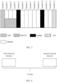
- the communication system includes a network device and six terminal devices, for example, UE 1 to UE 6.
- the UE 1 to the UE 6 may send signals to the network device on uplinks, and the network device may receive the uplink signals sent by the UE 1 to the UE 6.
- the UE 4 to the UE 6 may also form a sub-communication system.
- the network device may send downlink signals to the UE 1, the UE 2, the UE 3, and the UE 5 on downlinks.
- the UE 5 may send signals to the UE 4 and the UE 6 by using sidelinks (sidelink, SL) between terminals based on a V2X technology.
- FIG. 1 is merely a schematic diagram. This application sets no specific limitation on a type of the communication system, a quantity of devices included in the communication system, a type of the device, or the like.
- Network architectures and service scenarios described in embodiments of this application are intended to describe the technical solutions in embodiments of this application more clearly, and do not constitute a limitation on the technical solutions provided in embodiments of this application.
- a person of ordinary skill in the art may learn that with evolution of the network architectures and emergence of new service scenarios, the technical solutions provided in embodiments of this application are also applicable to similar technical problems.
- LTE starts to support device-to-device communication in a cellular network, which is referred to as D2D or Sidelink Communication.
- a D2D communication technology indicates a communication manner in which two peer user nodes directly communicate with each other.
- the D2D communication has different applications in different networks, for example, Wi-Fi direct connection (Direct) or a Bluetooth technology (short range time division duplexing communication) in a Wi-Fi network.
- the D2D aims to enable user communication devices to directly communicate with each other within a specific range, to reduce a load on a serving base station.
- the size of the layer 2 buffer may be understood as a sum of quantities of bytes (bytes) that can be stored by UE in an RLC transmission window, RLC receiving and reordering windows, and a PDCP reordering window on all radio bearers.
- the size of the layer 2 buffer in the Uu transmission is a sum of an uplink total buffer size and a downlink total buffer size.
- this application provides a buffer determining method and apparatus, to resolve a problem of how a terminal device on a sidelink calculates a buffer size.
- the method and an apparatus are based on a same inventive concept. Because the method and the apparatus have a similar problem-resolving principle, for implementations of the apparatus and the method, refer to each other, and no repeated description is provided.
- Uu described in embodiments of this application may be understood as a cellular link, and may include an uplink and a downlink.
- the cellular link is uniformly referred to as Uu in the following.
- cellular link communication is uniformly referred to as Uu communication
- cellular link transmission is uniformly referred to as Uu transmission
- cellular link round trip time is uniformly referred to as Uu round trip time.
- the terminal device and/or the network device may perform some or all of the steps in embodiments of this application. These steps or operations are merely examples. In embodiments of this application, other operations or variants of operations may be further performed. In addition, the steps may be performed in different sequences presented in embodiments of this application, and not all operations in embodiments of this application may need to be performed.
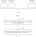
- FIG. 2 is a flowchart of a buffer determining method according to an embodiment of this application.
- the terminal device may determine a buffer size by using the method provided in Embodiment 1.
- the method includes: S201: A terminal device determines a sidelink data rate.
- the sidelink data rate may be understood as a rate at which the terminal device transmits data in SL communication.
- the sidelink data rate may include a sidelink transmit data rate.
- the sidelink data rate may include a sidelink receive data rate.
- the sidelink data rate may include a sidelink transmit data rate and a sidelink receive data rate.
- the sidelink data rate is a maximum value in a sidelink transmit data rate and a sidelink receive data rate.
- the sidelink transmit data rate may be a maximum volume of data sent by the terminal device in a unit time on a sidelink.
- the sidelink transmit data rate may be a maximum quantity of bits sent by the terminal device in 1 ms on a sidelink.
- the sidelink receive data rate may be a maximum volume of data received by the terminal device in a unit time on a sidelink.
- the sidelink receive data rate may be a maximum quantity of bits received by the terminal device in 1 ms on a sidelink.
- the sidelink transmit data rate may be determined based on one or more of the following parameters: a quantity of transmit layers, a transmit modulation order number, and an overhead.
- the quantity of transmit layers is a maximum quantity of sidelink transmit layers supported by the terminal device.
- the transmit modulation order number is a maximum modulation order number supported by the terminal device for sidelink transmission.
- the overhead is a parameter value greater than 0 and not greater than 1.
- the sidelink receive data rate may be determined based on one or more of the following parameters: a quantity of receive layers, a receive modulation order number, and an overhead.
- the quantity of receive layers is a maximum quantity of sidelink transmit layers supported by the terminal device.
- the receive modulation order number is a maximum modulation order number supported by the terminal device for sidelink reception.
- the overhead is a parameter value greater than 0 and not greater than 1.
- an overhead used by the terminal device when calculating the sidelink transmit data rate may be the same as or different from an overhead used by the terminal device when calculating the sidelink receive data rate.
- the sidelink transmit data rate may meet the following formula.
- SLTXDataRate is the sidelink transmit data rate.
- SLRXDataRate is the sidelink receive data rate.
- V Layers may be determined based on a transmission capability of UE.
- the sidelink transmit data rate meets the foregoing formula.
- V Layers may be a maximum quantity of transmit layers supported by the UE. For example, if the terminal device has a capability of supporting layer 2 sidelink transmission of a physical Sidelink shared channel (physical sidelink shared channel, PSSCH). In other words, when the terminal device can support PSSCH transmission at a rank 2, V Layers may be 2; or otherwise, V Layers may be 1.
- SLDataRate is the sidelink receive data rate. In other words, the sidelink receive data rate meets the foregoing formula.
- V Layers may be a maximum quantity of receive layers supported by the UE. For example, if the terminal device has a capability of supporting layer 2 sidelink reception of a PSSCH, that is, the terminal device supports PSSCH transmission at a rank 2, V Layers may be 2; or otherwise, V Layers may be 1.
- V Layers may be preconfigured, or V Layers may be predefined, or V Layers may be configured by a network device, or V Layers may be determined by a terminal device.
- Q m may be determined based on a capability of the UE.
- SLDataRate is the sidelink transmit data rate.
- the sidelink transmit data rate meets the foregoing formula.
- Q m may be a transmit modulation order number. For example, if the terminal device has a capability of supporting 256 quadrature amplitude modulation (quadrature amplitude modulation, QAM) transmission, Q m may be 8; or otherwise, Q m may be 6.
- QAM quadrature amplitude modulation
- SLDataRate is the sidelink receive data rate. In other words, the sidelink receive data rate meets the foregoing formula.
- Q m may be a receive modulation order number.
- Q m may be 8; or otherwise, Q m may be 6.
- Q m may be 8.
- f is an adjustment factor.
- f may be indicated by an upper-level parameter: a scaling factor (scalingFactor).
- scalingFactor scaling Factor
- f may be but is not limited to a value of 1, 0.8, 0.75, or 0.4.
- R max is a maximum target bit rate.
- R max may be 948 1024 .
- ⁇ is a granularity (numerology).
- T S ⁇ is an average orthogonal frequency division multiplexing (orthogonal frequency division multiplexing, OFDM) symbol length in a slot with a granularity of ⁇ .
- a cyclic prefix (cyclic prefix, CP) type is a normal CP (normal cyclic prefix, NCP)
- T s ⁇ 10 ⁇ 3 14 ⁇ 2 ⁇
- ECP extended CP
- ⁇ is a maximum quantity of allocated resource blocks (resource block, RB) in a bandwidth BW with a granularity of ⁇ .
- BW may be a maximum bandwidth supported by the terminal device in a given frequency band or frequency band combination.
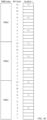
- OH is an overhead, and OH may be related to at least one of the following parameters: an automatic gain control (automatic gain control, AGC) symbol, a guard period (guard period, GP) symbol, a physical sidelink feedback channel (physical sidelink feedback channel, PSFCH) resource configuration period, and a reference signal (reference signal, RS). Not all symbols in a slot are used to transmit data. Some symbols are used for transmission of the AGC, the GP, the PSCCH, the PSFCH, and the reference signal. For example, as shown in FIG. 3 , one slot has 14 symbols, respectively a symbol 0 to a symbol 13.
- AGC automatic gain control
- guard period guard period
- PSFCH physical sidelink feedback channel
- RS reference signal
- the symbol 0 is used for the AGC, and the symbol 1 to the symbol 3 are used for transmission of a physical Sidelink control channel (physical sidelink control channel, PSCCH).
- the symbol 13 is the GP.
- the symbols 4 and 10 are the DMRS. Therefore, there are 10 symbols used to transmit data.
- OH may have at least one of the following correspondences:
- the DMRS occupies 1.5 symbols
- a channel state information reference signal (channel state information reference signal, CSI-RS) occupies 0 symbols
- a phase tracking reference signal (Phase Tracking Reference Signal, PT-RS) occupies 0 symbols
- sidelink control information (sidelink control information, SCI) occupies 0.38 symbols
- the GP occupies 1 symbol
- the AGC occupies 1 symbol.
- sl-PSFCH-Period-r16 is a parameter configured in a resource pool, and is used to indicate the PSFCH resource period.
- the PSFCH resource period is 1, the PSFCH occupies 3 symbols. Therefore, a quantity of symbols not used for data transmission is 6.88, and OH may be 0.49.
- the PSFCH resource period is 2
- the PSFCH occupies 1.5 symbols on average. Therefore, a quantity of symbols not used for data transmission is 5.38, and OH may be 0.38.
- the PSFCH resource period is 4, the PSFCH occupies 0.75 symbols on average. Therefore, a quantity of symbols not used for data transmission is 4.63, and OH may be 0.33.
- Table 1a PSFCH resource period PSFCH symbol quantity DMRS symbol quantity CSI-RS/PT-RS symbol quantity SCI symbol quantity GP symbol quantity
- Table 1b PSFCH resource period OH 0 0.28 1 0.49 2 0.38 4 0.33
- OH there is a correspondence between OH and each of the PSFCH resource period and the CP type.
- a different PSFCH resource period corresponds to a different CP type and a different overhead.
- a different PSFCH resource period and a different CR type correspond to a different overhead value.
- the DMRS occupies 1.5 symbols
- the CSI-RS/PT-RS occupies 0 symbols
- the SCI occupies 0.38 symbols
- the GP occupies 1 symbol
- the AGC occupies 1 symbol.
- the PSFCH occupies 0 symbols. Therefore, a quantity of symbols not used for data transmission is 3.88, and OH may be 3.88/14, which is approximately 0.28.
- the PSFCH resource period is 1, the PSFCH occupies 3 symbols on average. Therefore, a quantity of symbols not used for data transmission is 6.88, and OH may be 6.88/14, which is approximately 0.49.
- the PSFCH resource period is 2
- the PSFCH occupies 1.5 symbols on average. Therefore, a quantity of symbols not used for data transmission is 5.38, and OH may be 5.38/14, which is approximately 0.38.
- the PSFCH resource period is 4, the PSFCH occupies 0.75 symbols on average. Therefore, a quantity of symbols not used for data transmission is 4.63, and OH may be 4.63/14, which is approximately 0.33.
- the PSFCH occupies 0 symbols. Therefore, a quantity of symbols not used for data transmission is 3.88, and OH may be 3.88/12, which is approximately 0.32.
- the PSFCH resource period is 1, the PSFCH occupies 3 symbols on average. Therefore, a quantity of symbols not used for data transmission is 6.88, and OH may be 6.88/12, which is approximately 0.57.
- the PSFCH resource period is 2
- the PSFCH occupies 1.5 symbols on average. Therefore, a quantity of symbols not used for data transmission is 5.38, and OH may be 5.38/12, which is approximately 0.45.
- the PSFCH occupies 0.75 symbols on average. Therefore, a quantity of symbols not used for data transmission is 4.63, and OH may be 4.63/12, which is approximately 0.39.
- Table 2a CP type PSFCH resource period PSFCH symbol quantity DMRS symbol quantity CSI-RS/PT-RS symbol quantity SCI symbol quantity GP symbol quantity
- AGC symbol quantity Quantity of symbols not used for data transmission OH NCP 0 0 1.5 0 0.38 1 1 3.88 0.28 1 3 1.5 0 0.38 1 1 6.88 0.49 2 1.5 1.5 0 0.38 1 1 5.38 0.38 4 0.75 1.5 0 0.38 1 1 4.63 0.33 ECP 0 0 1.5 0 0.38 1 1 3.88 0.32 1 3 1.5 0 0.38 1 1 6.88 0.57 2 1.5 1.5 0 0.38 1 1 5.38 0.45 4 0.75 1.5 0 0.38 1 1 4.63 0.39
- Table 2b CP type PSFCH resource period OH NCP 0 0.28 1 0.49 2 0.38 4 0.33 ECP 0 0.32 1 0.57 2 0.45 4 0.39
- OH there is a correspondence between OH and the frequency range.
- a different frequency range corresponds to a different overhead.
- a different PSFCH resource period and a different CR type correspond to a different overhead value.
- the CP type is the NCP
- the PSFCH is not considered
- the DMRS occupies 1.5 symbols
- the SCI occupies 0.38 symbols
- the GP occupies 1 symbol
- the AGC occupies 1 symbol.
- the frequency range is FR1
- the CSI-RS/PT-RS occupies 0 symbols. Therefore, a quantity of symbols not used for data transmission is 3.88, and OH may be 3.88/14, which is approximately 0.277.
- the frequency range is FR2
- the CSI-RS/PT-RS occupies 0.01 symbols. Therefore, a quantity of symbols not used for data transmission is 3.89, and OH may be 3.89/14, which is approximately 0.278.
- Table 3a Frequency range PSFCH symbol quantity DMRS symbol quantity CSI-RS/PT-RS symbol quantity SCI symbol quantity GP symbol quantity
- PSFCH symbol quantity DMRS symbol quantity
- CSI-RS/PT-RS symbol quantity SCI symbol quantity
- GP symbol quantity AGC symbol quantity Quantity of symbols not used for data transmission OH FR1 0 1.5 0 0.38 1 1 3.88 0.277 FR2 3 1.5 0.01 0.38 1 1 3.89 0.278
- Table 3b Frequency range OH FR1 0.277 FR2 0.278
- the CP type is the ECP
- the PSFCH is not considered
- the DMRS occupies 1.5 symbols
- the SCI occupies 0.38 symbols
- the GP occupies 1 symbol
- the AGC occupies 1 symbol.
- the frequency range is FR1
- the CSI-RS/PT-RS occupies 0 symbols. Therefore, a quantity of symbols not used for data transmission is 3.88, and OH may be 3.88/12, which is approximately 0.323.
- the frequency range is FR2
- the CSI-RS/PT-RS occupies 0.01 symbols. Therefore, a quantity of symbols not used for data transmission is 3.89, and OH may be 3.89/12, which is approximately 0.324.
- Table 4a Frequency range PSFCH symbol quantity DMRS symbol quantity CSI-RS/PT-RS symbol quantity SCI symbol quantity GP symbol quantity
- PSFCH symbol quantity DMRS symbol quantity
- CSI-RS/PT-RS symbol quantity SCI symbol quantity
- GP symbol quantity AGC symbol quantity Quantity of symbols not used for data transmission OH FR1 0 1.5 0 0.38 1 1 3.88 0.323 FR2 3 1.5 0.01 0.38 1 1 3.89 0.324
- Table 4b Frequency range OH FR1 0.323 FR2 0.324
- the DMRS occupies 1.5 symbols
- the SCI occupies 0.38 symbols
- the GP occupies 1 symbol
- the AGC occupies 1 symbol.
- the correspondence between OH and each of the PSFCH resource period, the frequency range, and the CP type may be shown in Table 5a.
- Table 5b Frequency range CP type PSFCH resource period OH FR1 NCP 0 0.2771 1 0.4914 2 0.3843 4 0.3307 ECP 0 0.3233 1 0.5733 2 0.4483 4 0.3858 FR2 NCP 0 0.2779 1 0.4921 2 0.3850 4 0.3314 ECP 0 0.3242 1 0.5742 2 0.4492 4 0.3867
- OH OH
- PSFCH OH
- PSFCH 0
- OH may include a plurality of parameters.
- OH is equal to at least one or more of an overhead related to a PSFCH resource, an overhead related to the DMRS, an overhead related to the CSI-RS, an overhead related to the PT-RS, an overhead related to the GP, and an overhead related to the AGC.
- the overhead OH is equal to a sum of the PSFCH overhead, the RS overhead, the SCI overhead, the GP overhead, and the AGC overhead.
- OH is a range corresponding to a quantity of symbols occupied by the PSSCH.
- the quantity of symbols occupied by the PSSCH is 3-10, and a corresponding overhead value in a case of the NCP is 11-4 symbols.
- the corresponding OH range is 4/14 to 11-14, that is, from 0.29 to 0.71.
- precision of the overhead may be one decimal place, two decimal places, three decimal places, or the like.
- the precision of the overhead is not specifically limited herein.
- the overhead may be determined through rounding up when the overhead is calculated. For example, it is assumed that the precision of the overhead is two decimal places. If the calculated overhead value is 0.5733, the value of the overhead may be 0.58; or if the calculated overhead value is 0.4492, the value of the overhead may be 0.45; or the like.
- the overhead may be determined through rounding down when the overhead is calculated. For example, it is assumed that the precision of the overhead is two decimal places.
- the value of the overhead may be 0.57; or if the calculated overhead value is 0.4492, the value of the overhead may be 0.44; or the like.
- the overhead may be determined through rounding off when the overhead is calculated. For example, it is assumed that the precision of the overhead is two decimal places. If the calculated overhead value is 0.5733, the value of the overhead may be 0.57; or if the calculated overhead value is 0.4492, the value of the overhead may be 0.45; or the like. This is not specifically limited.
- the sidelink transmit data rate and the sidelink receive data rate may meet the following formula.
- J may be equal to 1.
- the sidelink communication that is, the V2X sidelink communication
- the terminal device determines a buffer size (buffer size) based on the sidelink data rate.
- the buffer size may be understood as a size of a buffer.
- the buffer size may be a total size of the layer 2 buffer.
- the buffer size may be defined as a sum of quantities of bytes (bytes) that can be stored within an RLC transmission window, RLC receiving and reordering windows, and a PDCP reordering window on all radio bearers.
- the buffer size may be further defined as a sum of quantities of bytes that can be stored within a PDCP reordering window on all radio bearers.
- the buffer size may be further defined as a sum of quantities of bytes that can be stored by the terminal device in a sidelink round trip time.
- the terminal device may determine the buffer size based on the sidelink data rate and the sidelink round trip time (round trip time, RTT).
- the sidelink round trip time is a round trip time (round trip time, RTT) at a radio link control (radio link control, RLC) layer in the SL communication.
- the sidelink round trip time may further be a round trip time at a PDCP layer in the sidelink communication.
- the sidelink round trip time may further be a reordering time at a PDCP layer in the sidelink communication.
- the sidelink round trip time may further be an RLC layer round trip time in a unicast scenario, or may be a maximum value in round trip times corresponding to unicast, multicast, and broadcast.
- the sidelink data rate is a maximum value in calculated sidelink data rates for frequency bands and/or frequency band combinations.
- Buffer Size is the buffer size
- SLTXDataRate is the sidelink transmit data rate, or a maximum value in calculated sidelink transmit data rates for supported frequency bands or frequency band combinations
- SLRXDataRate is the sidelink receive data rate, or a maximum value in calculated sidelink receive data rates for supported frequency bands or frequency band combinations
- SL RTT is the sidelink round trip time
- a product of SLTXDataRate and SL RTT is a sidelink transmit buffer size, and a product of SLRXDataRate and SL RTT is a sidelink receive buffer size.
- Buffer Size is the buffer size
- SLTXDataRate is the sidelink transmit data rate, or a maximum value in calculated sidelink transmit data rates for supported frequency bands or frequency band combinations
- SLRXDataRate is the sidelink receive data rate, or a maximum value in calculated sidelink receive data rates for supported frequency bands or frequency band combinations
- SL TX RTT is the sidelink transmit-side round trip time
- SL RX RTT is a sidelink receive-side round trip time.
- Buffer Size is the buffer size
- SLDataRate is the sidelink transmit data rate, or a maximum value in calculated sidelink transmit data rates for supported frequency bands or frequency band combinations, or the sidelink receive data rate, or a maximum value in calculated sidelink receive data rates for supported frequency bands or frequency band combinations, or a maximum value in the sidelink transmit data rate and the sidelink receive data rate, or a larger value of a maximum value in calculated sidelink transmit data rates for supported frequency bands or frequency band combinations and a maximum value in calculated sidelink receive data rates for supported frequency bands or frequency band combinations; and SL RTT is the sidelink round trip time.
- a correspondence between the sidelink round trip time and subcarrier spacing (subcarrier space, SCS) of a sidelink frequency band may be but is not limited to a form such as a table, a list, or a formula.
- the sidelink round trip time may be determined based on a first list.
- the first list includes a round trip time corresponding to subcarrier spacing of at least one sidelink frequency band.
- Multiplexing can be implemented between the sidelink round trip time and an RLC RTT of an NR cell group.
- the RTT in the SL communication and the RTT in the Uu communication are determined based on the same list, that is, the first list.
- the first list may be shown in Table 6.
- Table 6 SCS RTT (ms) 15 kHz 50 30 kHz 40 60 kHz 30 120 kHz 20
- the first list may be a list defined for the SL communication.
- the sidelink round trip time is related to a cast (cast) type.
- the cast type may include one or more of unicast, multicast, and broadcast.
- the sidelink round trip time corresponds to different values in different cast types.
- the RTT preconfigured in each resource pool has three values, which may be respectively a unicast RTT, a broadcast RTT, and a multicast RTT.
- the sidelink round trip time the unicast RTT + the multicast RTT + the broadcast RTT.
- the RTT may have one or more values. Different values of the RTT represent different buffer levels.
- the sidelink round trip time is predefined, preconfigured, or preconfigured or configured in each resource pool.
- the values of the sidelink round trip time are different in different granularities, and these values are preconfigured for each resource pool.
- each granularity is related to a plurality of sidelink round trip times, including a sidelink round trip time corresponding to sidelink transmission and a sidelink round trip time corresponding to sidelink reception.
- the sidelink round trip time related to each granularity has a plurality of values, and the plurality of values correspond to a delay level or a buffer level.
- the sidelink round trip time includes a sidelink transmit-side round trip time and a sidelink receive-side round trip time.
- the sidelink transmit-side round trip time and the sidelink receive-side round trip time are separately configured or pre-configured or predefined.
- the sidelink transmit-side round trip time and the sidelink receive-side round trip time may be separately preconfigured in a protocol.
- Each SCS is related to a different value. For example, when the SCS is 15 kHz, a related RTT may be a first value; or when the SCS is 30 kHz, a related RTT may be a second value.
- the sidelink round trip time may be a round trip time of an RLC layer.
- the sidelink round trip time may be a time interval between initial transmission and retransmission of the RLC layer.
- the sidelink round trip time may be determined based on a hybrid automatic repeat request (hybrid automatic repeat request, HARQ) round trip time and a time length of RLC polling.
- HARQ hybrid automatic repeat request
- reserved resources are in 32 slots.
- resources reserved in one transport block within one resource reservation period need to be in 32 slots.
- the terminal device may reserve two resources.
- a first reserved resource is used for the initial transmission, and a second reserved resource is used for the retransmission.
- a time interval between the initial transmission and first possible retransmission may be a maximum of 31 slots.
- a HARQ RTT may be a maximum of 31 slots, and the HARQ RTT may be understood as the time interval between the initial transmission and the retransmission.
- the terminal device may alternatively reserve three resources.
- a first reserved resource is used for the initial transmission, and remaining resources are used for the retransmission.
- a time interval between the first reserved resource and a second reserved resource may be a minimum of 1.
- a HARQ RTT may be a minimum of 1 slot.
- a quantity of reserved resources of the terminal device is not limited to two or three, or may be another number. This is not specifically limited herein.
- the sidelink round trip time may be a sum of a time length of RLC polling and n times a maximum value (that is, 31 slots) of a HARQ round trip time.
- n is an integer greater than 0.
- n is 5. If the SCS is 15 kHz, a time length of one slot is 1 ms, a time length of RLC polling is 32 ms, and a sidelink round trip time is 187 ms. If the SCS is 30 kHz, a time length of one slot is 0.5 ms, a time length of RLC polling is 16 ms, and a sidelink round trip time is 94 ms. If the SCS is 60 kHz, a time length of one slot is 0.25 ms, a time length of RLC polling is 8 ms, and a sidelink round trip time is 47 ms. If the SCS is 120 kHz, a time length of one slot is 0.125 ms, a time length of RLC polling is 4 ms, and a sidelink round trip time is 23 ms.
- a correspondence between the sidelink round trip time and the SCS may be shown in Table 7.
- Table 7 SCS Sidelink round trip time (ms) 15 kHz 187 30 kHz 94 60 kHz 47 120 kHz 23
- the sidelink round trip time may be a sum of a time length of RLC polling and n times a minimum value (that is, 1 slot) of a HARQ round trip time.
- n is 5.
- a correspondence between the sidelink round trip time and the SCS may be shown in Table 8.
- Table 8 SCS Sidelink round trip time (ms) 15 kHz 37 30 kHz 19 60 kHz 9 120 kHz 5
- the sidelink round trip time is an average value of a first value and a second value.
- the first value is a sum of a time length of RLC polling and n times a maximum value (that is, 31 slots) of a HARQ round trip time
- the second value is a sum of the time length of the RLC polling and n times a minimum value (that is, 1 slot) of the HARQ round trip time.
- n 5
- SCS Sidelink round trip time (ms) 15 kHz 112 30 kHz 56 60 kHz 28 120 kHz 14
- the sidelink round trip time may be m times a maximum value (that is, 31 slots) of a HARQ round trip time.
- m is an integer greater than 0.
- m is 6.
- Table 10a SCS Sidelink round trip time (ms) 15 kHz 186 30 kHz 93 60 kHz 47 120 kHz 23
- m is 32.
- a correspondence between the sidelink round trip time and the SCS may be shown in Table 10b.
- Table 10b SCS Sidelink round trip time (ms) 15 kHz 992 30 kHz 496 60 kHz 248 120 kHz 124
- the sidelink round trip time may be m times a minimum value (that is, 1 slot) of a HARQ round trip time.
- m is 6.
- a correspondence between the sidelink round trip time and the SCS may be shown in Table 11a.
- Table 11a SCS Sidelink round trip time (ms) 15 kHz 6 30 kHz 3 60 kHz 2 120 kHz 1
- m is 32.
- a correspondence between the sidelink round trip time and the SCS may be shown in Table 11b.
- Table 11b SCS Sidelink round trip time (ms) 15 kHz 32 30 kHz 16 60 kHz 8 120 kHz 4
- the sidelink round trip time is an average value of a third value and a fourth value.
- the third value is m times a maximum value (that is, 31 slots) of a HARQ round trip time
- the fourth value is m times a minimum value (that is, 1 slot) of the HARQ round trip time.
- m is 6.
- a correspondence between the sidelink round trip time and the SCS may be shown in Table 12a.
- Table 12a SCS Sidelink round trip time (ms) 15 kHz 96 30 kHz 48 60 kHz 24 120 kHz 12
- m is 32.
- a correspondence between the sidelink round trip time and the SCS may be shown in Table 12b.
- Table 12b SCS Sidelink round trip time (ms) 15 kHz 512 30 kHz 256 60 kHz 128 120 kHz 64
- the terminal device may further determine, based on the sidelink data rate, whether to process the PSSCH.
- the terminal device may further determine, based on the sidelink data rate, whether to process the PSSCH.
- the terminal device determines, based on the sidelink data rate, whether to process the PSSCH. Details are not described herein.
- the terminal device may calculate the buffer size based on the maximum value in the sidelink transmit data rate and the sidelink receive data rate. Because the sidelink transmit data rate may be different from the sidelink receive rate, a larger value is selected to determine the buffer, so that the buffer size can be more accurately calculated. In this way, the determined buffer size can meet a sidelink communication requirement of the terminal device, thereby improving communication quality of the sidelink communication.
- FIG. 6A is a flowchart of another buffer determining method according to this application.
- the terminal device may determine a buffer size by using a method provided in Embodiment 2.
- the method includes: S601: The terminal device determines a sidelink data rate, a downlink data rate, and an uplink data rate.
- the downlink data rate may be a maximum volume of uplink data sent by the terminal device in a unit time.
- the uplink data rate may be a maximum quantity of uplink bits sent by the terminal device in 1 ms.
- the downlink data rate may be a maximum volume of downlink data received by the terminal device in a unit time.
- the downlink data rate may be a maximum quantity of downlink bits received by the terminal device in 1 ms.
- the uplink data rate and the downlink data rate may meet the following formula.
- J is a quantity of aggregated carriers in a frequency band or a frequency band combination.
- v Layers j may be a maximum quantity of supported layers.
- v Layers j may be indicated by an upper-layer parameter maxNumberMIMO-LayersPDSCH.
- v Layers j may be indicated by upper-layer parameters maxNumberMIMO-LayersCB-PUSCH and maxNumberMIMO-LayersNonCB-PUSCH.
- Q m j is a maximum modulation order number supported by the terminal device.
- Q m j may be indicated by an upper-layer parameter supportedModulationOrderDL.
- Q m j may be indicated by an upper-layer parameter supportedModulationOrderUL.
- OH is an overhead.
- a downlink frequency range is FR1, OH may be 0.14.
- a downlink frequency range is FR2, OH may be 0.18.
- an uplink frequency range is FR1, OH may be 0.08.
- OH may be 0.10.
- the terminal device determines a buffer size based on the sidelink data rate, the downlink data rate, and the uplink data rate.
- the terminal device may determine the buffer size based on the sidelink transmit data rate, the sidelink receive data rate, the downlink data rate, the uplink data rate, the sidelink round trip time, and the Uu round trip time.
- the Uu round trip time is an RLC layer round trip time in the Uu communication.
- the buffer size may be determined based on a sidelink transmit buffer size, a sidelink receive buffer size, an uplink buffer size, and a downlink buffer size.
- the buffer size may be equal to a sum of the sidelink transmit buffer size, the sidelink receive buffer size, the uplink buffer size, and the downlink buffer size.
- the buffer size may meet the following formula.
- Buffer Size is the buffer size
- MaxULDataRate is the uplink data rate
- MaxDLDataRate is the downlink data rate
- RLC RTT is the Uu round trip time
- SLTXDataRate is the sidelink transmit data rate, or a maximum value in sidelink transmit data rates calculated for supported frequency bands or frequency band combinations
- SLRXDataRate is the sidelink receive data rate, or a maximum value in sidelink receive data rates calculated for supported frequency bands or frequency band combinations
- SL RTT is the sidelink round trip time
- a product of SLTXDataRate and SL RTT is the sidelink transmit buffer size
- a product of SLRXDataRate and SL RTT is a sidelink receive buffer size.
- Buffer Size is the buffer size
- SLTXDataRate is the sidelink transmit data rate, or a maximum value in sidelink transmit data rates calculated for supported frequency bands or frequency band combinations
- SLRXDataRate is the sidelink receive data rate, or a maximum value in sidelink receive data rates calculated for supported frequency bands or frequency band combinations
- SL TX RTT is the sidelink transmit-side round trip time
- SL RX RTT is the sidelink receive-side round trip time.
- the buffer size may be equal to a sum of the sidelink buffer size, the uplink buffer size, and the downlink buffer size.
- the buffer size may meet the following formula.
- Buffer Size is the buffer size
- MaxULDataRate is an uplink data rate or a maximum value in calculated uplink data rates for frequency bands or frequency band combinations
- MaxDLDataRate is a downlink data rate or maximum value in calculated downlink data rates for frequency bands or frequency band combinations
- RLC RTT is the Uu round trip time
- SLDataRate is the sidelink transmit data rate, or a maximum value in calculated sidelink transmit data rates for supported frequency bands or frequency band combinations
- SLRXDataRate is the sidelink receive data rate, or a maximum value in calculated sidelink receive data rates for supported frequency bands or frequency band combinations
- SL RTT is the sidelink transmit-side round trip time.
- the terminal device may further determine, based on the sidelink data rate, whether to process the PSSCH. For example, the terminal device may further determine whether the PSSCH meets a preset condition. The preset condition is related to the sidelink round trip time. If the PSSCH meets the preset condition, the terminal device processes the PSSCH. If the PSSCH does not meet the preset condition, the terminal device may not be required to process the PSSCH.
- the preset condition is related to the sidelink round trip time. If the PSSCH meets the preset condition, the terminal device processes the PSSCH. If the PSSCH does not meet the preset condition, the terminal device may not be required to process the PSSCH.
- the preset condition may include a first condition, or the preset condition may include a second condition, or the preset condition may include a first condition and a second condition, or the preset condition may include a condition with a higher priority in a first condition and a second condition, or the preset condition may include a condition with a lower priority in a first condition and a second condition.
- a priority of the first condition may be higher than that of the second condition, or may be lower than that of the second condition. This is not specifically limited herein.
- the first condition may be as follows: V j L ⁇ T S ⁇ ⁇ SLDataRate
- L is a quantity of symbols allocated to the PSSCH, where an AGC symbol, an RS symbol, a GP symbol, and a PSFCH symbol are not included.
- T S ⁇ 10 ⁇ 3 2 ⁇ ⁇ N symb slot , where ⁇ is a granularity of the PSSCH, or a granularity of a corresponding frequency band/serving cell/partial bandwidth/resource pool.
- V j C ′ ⁇ A C , where A is a quantity of bits in the transport block, C is a total quantity of code blocks in the transport block, and C' is a quantity of scheduled code blocks in the transport block.
- SLDataRate is a maximum data rate on a carrier of a frequency band of a serving cell in any frequency band or frequency band combination and a feature set.
- SLDataRate may be the sidelink transmit data rate, may be the sidelink receive data rate, or may be a maximum value in the sidelink transmit data rate and the sidelink receive data rate.
- the terminal device in a serving cell j, if the terminal device does not meet the first condition, the terminal device is not required to process the PSSCH.
- the second condition may be as follows: TBS L ⁇ T S ⁇ ⁇ SLDataRate
- L is a quantity of symbols allocated to the PSSCH, where an AGC symbol, an RS symbol, a GP symbol, and a PSFCH symbol are not included.
- T S ⁇ 10 ⁇ 3 2 ⁇ ⁇ N symb slot , where ⁇ is a granularity of the PSSCH, or a granularity of a corresponding frequency band/serving cell/partial bandwidth/resource pool.
- TBS is a size of a transport block.
- SLDataRate is a maximum data rate on a carrier of a frequency band of a serving cell in any frequency band or frequency band combination and a feature set.
- SLDataRate may be the sidelink transmit data rate, may be the sidelink receive data rate, or may be a maximum value in the sidelink transmit data rate and the sidelink receive data rate.
- the terminal device on a sidelink carrier, if the terminal device does not meet the second condition, the terminal device is not required to process the PSSCH.
- the terminal device may determine the buffer size based on the sidelink data rate, the uplink data rate, and the downlink data rate, to implement calculation of a layer 2 buffer of UE in V2X sidelink communication and NR sidelink communication.
- Embodiment 1 and Embodiment 2 may be separately implemented as independent solutions, or may be combined and implemented as one solution.
- Embodiment 3 an embodiment of this application provides a reference signal sending method.
- the method includes: A terminal device determines N resource blocks RBs on symbols.
- N is an odd number.
- a reference signal DMRS of a control channel is mapped on N-1 RBs by using an orthogonal code with a length of 2.
- a DMRS of a control channel or a DMRS of a data channel is mapped on the remaining RB in the following manner: mapping the DMRS of the control channel by using an orthogonal code with a length of 2, mapping the DMRS of the control channel by using an orthogonal code with a length of 3, or mapping the DMRS of the data channel.
- the terminal device sends the DMRS on the symbols.
- mapping the reference signal DMRS of the control channel on the N-1 RBs includes: mapping the reference signal DMRS of the control channel on a first RB to an (N-1) th RB; or mapping the reference signal DMRS of the control channel on a second RB to an N th RB.
- each of the N-1 RBs on which the DMRS of the control channel is mapped has three resource elements REs used to carry the DMRS of the control channel.
- each two adjacent RBs of the N-1 RBs on which the DMRS of the control channel is mapped have six REs used to carry the DMRS of the control channel.
- the six REs are generated based on three orthogonal codes with a length of 2.
- the orthogonal cover code with the length of 2 has two sequence values: 1 and 1, or 1 and -1.
- a quantity of resource blocks (Resource Block, RB) of a candidate PSCCH is configured for each resource pool.
- the quantity belongs to a set ⁇ 10, 12, 15, 20, 25 ⁇ .
- Each RB includes 12 REs.
- a length of a frequency-domain orthogonal cover code (Orthogonal Cover Codes, OCC) of the PSCCH is 2, the orthogonal cover code has two sequence values: 1 and 1, or 1 and -1.
- OCC Orthogonal Cover Codes
- three REs in one RB are used to map the PSCCH DMRS.
- Mapping the PSCCH DMRS may also be described as carrying the PSCCH DMRS.
- a quantity of candidate RBs of the PSCCH is an odd number
- a corresponding quantity of REs used to map the PSCCH DMRS is an odd number.
- a quantity of candidate RBs of one PSCCH is an odd number, for example, the quantity of candidate RBs of the PSCCH is 15, and three REs in one RB are used to map the DMRS, a quantity of REs that can be used to map the PSCCH DMRS in one symbol is 45 that is an odd number. Because there are three RE locations in one RB for mapping the DMRS, two values of one OCC sequence are respectively located in two adjacent RBs. In this case, an OCC sequence in one RB cannot be fully mapped. When the OCC is equal to 2, the three REs can only be mapped as +1, +1, and +1. There is no other sequence value matching a sequence value of the third RE. In this case, orthogonality of the OCC cannot be ensured, and interference of different users is reduced.
- the PSCCH DMRS is mapped on N-1 RBs by using an orthogonal code with a length of 2
- the PSCCH DMRS is mapped on the remaining RB by using an orthogonal code with a length of 2.
- the PSCCH DMRS is mapped on N-1 RBs by using an orthogonal code with a length of 2, and the PSCCH DMRS is mapped on the remaining RB by using an orthogonal code with a length of 3.
- a problem that orthogonality cannot be ensured due to an occurrence of unmatched orthogonal codes is resolved, to avoid a problem of transmission interference between users.
- the PSCCH DMRS is mapped on N-1 RBs by using an orthogonal code with a length of 2, and the PSSCH DMRS is mapped on the remaining RB.
- Two values of one orthogonal code may appear in pairs, to ensure orthogonality of the orthogonal code.
- the PSCCH DMRS is mapped on N-1 RBs by using an orthogonal code with a length of 2, and the PSCCH DMRS is mapped on the remaining RB.
- the last RE of the three REs is not used to map the PSCCH DMRS; or is used to map the PSSCH DMRS; or is used to map the PSCCH; or is not used to transmit any channel or signal.
- the terminal device does not perform DMRS mapping at one RE location of one RB.
- the location is used to map the PSCCH, or the location is used to map the PSSCH, or the RB is used to map the PSSCH.
- the RB may be an RB with a smallest index in the candidate RBs of the PSCCH, or an RB with a largest index in the candidate RBs of the PSCCH, or any RB in the candidate RBs of the PSCCH, or the last RB when the DMRS is mapped on the candidate RBs of the PSCCH.
- the RE location may be any RE location in the RB, a last RE location in the RB, or a first RE location in the RB.
- a quantity of REs that can be used to map the PSCCH DMRS in one symbol is an odd number
- one of locations of the REs that can be used to map the PSCCH DMRS is not used.
- the location corresponds to one of the REs. Puncturing may be performed at the location.
- the location is skipped to further map the PSCCH DMRS.
- the location is used to map the PSCCH or the PSSCH. Because a quantity of REs is an odd number, when a quantity of frequency domain OCCs of the PSCCH DMRS is 2, an orthogonal effect of the orthogonal cover code cannot be ensured, and effect of channel estimation becomes poor.
- An advantage of this method is that it is unnecessary to use the RE corresponding to the location, and the location can be saved for other use.
- the other use herein includes mapping the PSCCH or the PSSCH DMRS.
- a quantity of REs used to carry the PSCCH DMRS in one RB is 3. It can be learned that OCCs used by an RB 1 and an RB 2 are equal to 2. As shown in FIG. 6B , an RE location 12 of the RB 1 and an RE location 4 of the RB 2 are two sequences [1, 1] of one OCC.
- RE locations 4 and 8 of the RB 1 are two sequence values of one OCC
- the RE location 12 of the RB 1 and the RE location 4 of the RB 2 are two sequence values of one OCC
- an RE location 8 of the RB 2 and an RE location 12 of the RB 2 are two sequence values of one OCC
- RE locations 4 and 8 of an RB 3 are two sequence values of one OCC.
- An RE location 12 of the RB 3 does not have the other paired sequence value of the OCC. This affects interference degrees of different users in the same resource transmission, and increases the interference degrees, because orthogonality of the OCC cannot be ensured.
- one RE in the RB 3 may not be used to map the DMRS.
- the RE location 12 of the RB 3 is not used to map the DMRS.
- the location may be used to map the PSCCH or the PSSCH DMRS.
- the RB 3 may be used to map the PSSCH DMRS, and is not used to map the PSCCH DMRS.
- the RB 1 and the RB 2 are used to map the PSCCH DMRS, and use an orthogonal code with a length of 2; and the RB 3 is not used to map the PSCCH DMRS, or the RB 3 is used to map the PSSCH DMRS.
- the RB 1 and the RB 2 are used to map the PSCCH DMRS, and use an orthogonal code with a length of 2.
- the RB 3 is used to map the PSCCH DMRS, and use an orthogonal code with a length of 2.
- the RE location 12 is not used to map the PSCCH DMRS, or is used to map the PSSCH DMRS.
- the RE locations 4, 8, and 12 of the RB 3 are used to map the PSCCH (including a first-level SCI and a second-level SCI).
- the PSCCH DMRS is mapped on the RB 3 by using an orthogonal code with a length of 3.
- the RB 3 is used to map the PSSCH DMRS.
- the RB 3 is used to map the PSSCH.
- an embodiment of this application provides a buffer determining apparatus.
- a structure of the apparatus may be shown in FIG. 7 , including a storage unit 701 and a processing unit 702.
- the apparatus may be specifically configured to implement the method performed by the terminal device in embodiments described in FIG. 2 to FIG. 5 .
- the apparatus may be the terminal device, or may be a chip, a chip group, or a part of a chip for performing related functions in the method in the terminal device.
- the storage unit is configured to store code instructions.
- the processing unit 702 is configured to: determine a sidelink data rate, and determine a buffer size based on the sidelink data rate.
- the processing unit 702 when determining the buffer size based on the sidelink data rate, is specifically configured to determine the buffer size based on the sidelink data rate and a sidelink round trip time.
- the sidelink data rate includes a sidelink transmit data rate and/or a sidelink receive data rate.
- the sidelink data rate is a maximum value in the sidelink transmit data rate and the sidelink receive data rate.
- the sidelink transmit data rate is determined based on a quantity of transmit layers, a transmit modulation order number, and an overhead.
- the quantity of transmit layers is a maximum quantity of sidelink transmit layers supported by the terminal device.
- the transmit modulation order number is a maximum modulation order number supported by the terminal device for sidelink transmission.
- the overhead is a parameter value greater than 0 and not greater than 1.
- SLTXDataRate is the sidelink transmit data rate
- V Layers is the quantity of transmit layers
- Q m is the transmit modulation order number
- f is an adjustment factor
- R max is a maximum target bit rate
- T s ⁇ is an average symbol length in a slot
- N PRB BW is a maximum quantity of allocated resource blocks in a bandwidth
- OH is the overhead.
- the sidelink receive data rate is determined based on a quantity of receive layers, a receive modulation order number, and an overhead.
- the quantity of receive layers is a maximum quantity of sidelink receive layers supported by the terminal device.
- the receive modulation order number is a maximum modulation order number supported by the terminal device for sidelink reception.
- the overhead is a parameter value greater than 0 and not greater than 1.
- SLRXDataRate is the sidelink receive data rate
- V Layers is the quantity of receive layers
- Q m is the receive modulation order number
- f is an adjustment factor
- R max is a maximum target bit rate
- T s ⁇ is an average symbol length in a slot
- N PRB BW is a maximum quantity of allocated resource blocks in a bandwidth
- OH is the overhead.
- the overhead has at least one of the following correspondences:
- Buffer Size is the buffer size
- SLTXDataRate is the sidelink transmit data rate
- SLRXDataRate is the sidelink receive data rate
- SL RTT is the sidelink round trip time
- Buffer Size is the buffer size
- SLDataRate is the maximum value in the sidelink transmit data rate and the sidelink receive data rate, or SLDataRate is the sidelink receive data rate, or SLDataRate is the sidelink transmit data rate
- SL RTT is the sidelink round trip time
- the sidelink round trip time is determined based on a first list.
- the first list includes a round trip time corresponding to subcarrier spacing of at least one sidelink frequency band.
- the sidelink round trip time is a sum of a maximum value of a HARQ round trip time and a time length of RLC polling;
- the processing unit 702 may be further configured to determine a downlink data rate and an uplink data rate.
- the processing unit 702 may be specifically configured to determine the buffer size based on the sidelink data rate, the downlink data rate, and the uplink data rate.
- the processing unit 702 may be specifically configured to determine the buffer size based on the sidelink data rate, the downlink data rate, the uplink data rate, a sidelink round trip time, and a Uu round trip time.
- the Uu round trip time is an RLC layer round trip time in Uu communication.
- Buffer Size is the buffer size
- MaxULDataRate is the uplink data rate
- MaxDLDataRate is the downlink data rate
- RLC RTT is the Uu round trip time
- SLTXDataRate is the sidelink transmit data rate
- SLRXDataRate is the sidelink receive data rate
- SL RTT is the sidelink round trip time
- Buffer Size is the buffer size
- MaxULDataRate is the uplink data rate
- MaxDLDataRate is the downlink data rate
- RLC RTT is the Uu round trip time
- SLDataRate is the maximum value in the sidelink transmit data rate and the sidelink receive data rate
- SLDataRate is the sidelink receive data rate
- SLDataRate is the sidelink transmit data rate
- SL RTT is the sidelink round trip time
- the processing unit 702 may be further configured to: determine whether the sidelink data rate meets a preset condition, and process a physical sidelink shared channel PSSCH when the sidelink data rate meets the preset condition.
- the preset condition may include at least one of a first condition and a second condition, or the preset condition may include a condition with a higher priority in a first condition and a second condition, or the preset condition may include a condition with a lower priority in a first condition and a second condition.
- the first condition is as follows: V j L ⁇ T S ⁇ ⁇ SLDataRate
- L is a quantity of symbols included in the PSSCH
- T S ⁇ 10 ⁇ 3 2 ⁇ ⁇ N symb slot
- ⁇ is a granularity of the PSSCH
- V j C ′ ⁇ A C
- A is a quantity of bits in a transport block
- C is a total quantity of code blocks in the transport block
- C' is a quantity of scheduled code blocks in the transport block
- SLDataRate is the sidelink data rate.
- SLDataRate may be the sidelink transmit data rate, may be the sidelink receive data rate, or may be a maximum value in the sidelink transmit data rate and the sidelink receive data rate.
- the second condition is as follows: TBS L ⁇ T S ⁇ ⁇ SLDataRate
- L is a quantity of symbols included in the PSSCH
- T S ⁇ 10 ⁇ 3 2 ⁇ ⁇ N symb slot
- ⁇ is a granularity of the PSSCH
- TBS is a size of the transport block
- SLDataRate is the sidelink data rate.
- SLDataRate may be the sidelink transmit data rate, may be the sidelink receive data rate, or may be a maximum value in the sidelink transmit data rate and the sidelink receive data rate.
- the apparatus may be specifically configured to implement the method performed by the terminal device in the embodiment described in FIG. 6A .
- the apparatus may be the terminal device, or may be a chip, a chip group, or a part of a chip for performing related functions in the method in the terminal device.
- the storage unit 701 is configured to store code instructions.
- the processing unit 702 is configured to: determine the sidelink data rate, the downlink data rate, and the uplink data rate, and determine the buffer size based on the sidelink data rate, the downlink data rate, and the uplink data rate.
- the processing unit 702 may be specifically configured to determine the buffer size based on the sidelink data rate, the downlink data rate, the uplink data rate, a sidelink round trip time, and a Uu round trip time of a common user.
- the Uu round trip time is an RLC layer round trip time in Uu communication.
- the sidelink data rate includes the sidelink transmit data rate and/or the sidelink receive data rate.
- the sidelink data rate is a maximum value in the sidelink transmit data rate and the sidelink receive data rate.
- the sidelink transmit data rate is determined based on a quantity of transmit layers, a transmit modulation order number, and an overhead.
- the quantity of transmit layers is a maximum quantity of sidelink transmit layers supported by the terminal device.
- the transmit modulation order number is a maximum modulation order number supported by the terminal device for sidelink transmission.
- the overhead is a parameter value greater than 0 and not greater than 1.
- SLTXDataRate is the sidelink transmit data rate
- V Layers is the quantity of transmit layers
- Q m is the transmit modulation order number
- f is an adjustment factor
- R max is a maximum target bit rate
- T S ⁇ is an average symbol length in a slot
- N PRB BW is a maximum quantity of allocated resource blocks in a bandwidth
- OH is the overhead.
- the sidelink receive data rate is determined based on a quantity of receive layers, a receive modulation order number, and an overhead.
- the quantity of receive layers is a maximum quantity of sidelink receive layers supported by the terminal device.
- the receive modulation order number is a maximum modulation order number supported by the terminal device for sidelink reception.
- the overhead is a parameter value greater than 0 and not greater than 1.
- SLRXDataRate is the sidelink receive data rate
- v Layers is the quantity of receive layers
- Q m is the receive modulation order number
- f is an adjustment factor
- R max is a maximum target bit rate
- T S ⁇ is an average symbol length in a slot
- N PRB BW is a maximum quantity of allocated resource blocks in a bandwidth
- OH is the overhead.
- the overhead has at least one of the following correspondences:
- Buffer Size is the buffer size
- MaxULDataRate is the uplink data rate
- MaxDLDataRate is the downlink data rate
- RLC RTT is the Uu round trip time
- SLTXDataRate is the sidelink transmit data rate
- SLRXDataRate is the sidelink receive data rate
- SL RTT is the sidelink round trip time
- Buffer Size is the buffer size
- MaxULDataRate is the uplink data rate
- MaxDLDataRate is the downlink data rate
- RLC RTT is the Uu round trip time
- SLDataRate is the maximum value in the sidelink transmit data rate and the sidelink receive data rate
- SLDataRate is the sidelink receive data rate
- SLDataRate is the sidelink transmit data rate
- SL RTT is the sidelink round trip time
- the sidelink round trip time is determined based on a first list.
- the first list includes a round trip time corresponding to subcarrier spacing of at least one sidelink frequency band.
- the sidelink round trip time is a sum of a maximum value of a HARQ round trip time and a time length of RLC polling
- division into the units is an example, is merely division into logical functions, and may be other division during actual implementation.
- functional units in embodiments of this application may be integrated into one processor, or each of the units may exist alone physically, or two or more units may be integrated into one unit.
- the integrated unit may be implemented in a form of hardware, or may be implemented in a form of a software functional unit. It may be understood that for functions or implementations of the units in embodiments of this application, reference may be further made to corresponding descriptions in the method embodiments.
- the communication apparatus may be shown in FIG. 8 .
- the communication apparatus may be a terminal device or a chip in a terminal device.
- the communication apparatus may include a processor 801, a communication interface 802, and a memory 803.
- the processing unit 702 may be the processor 801.
- the storage unit 701 may be the memory 803.
- the processor 801 may be a central processing unit (central processing unit, CPU for short), a digital processing unit, or the like.
- the communication interface 802 may be a transceiver, may be an interface circuit such as a transceiver circuit, may be a transceiver chip, or the like.
- the communication apparatus further includes the memory 803 configured to store a program executed by the processor 801.
- the memory 803 may be a non-volatile memory such as a hard disk drive (hard disk drive, HDD) or a solid-state drive (solid-state drive, SSD), or may be a volatile memory (volatile memory) such as a random access memory (random-access memory, RAM).
- the memory 803 is any other medium that can carry or store expected program code in a form of an instruction or a data structure and can be accessed by a computer, but is not limited thereto.
- the processor 801 is configured to execute the program code stored in the memory 803, and is specifically configured to perform operations of the processing unit 702. Details are not described herein again in this application.
- a specific connection medium between the communication interface 802, the processor 801, and the memory 803 is not limited.
- the memory 803, the processor 801, and the communication interface 802 are connected by using a bus 807 in FIG. 8 .
- the bus is represented by using a bold line in FIG. 8 .
- the foregoing is merely an example for description.
- a connection manner of other components is not limited thereto.
- the bus may be classified into an address bus, a data bus, a control bus, and the like. For ease of representation, only one thick line is for representing the bus in FIG. 8 , but this does not mean that there is only one bus or only one type of bus.
- An embodiment of the present invention further provides a computer-readable storage medium, configured to store computer software instructions used to execute operations that need to be executed by the processor.
- the computer software instructions include a program used to execute the operations that need to be executed by the processor.
- inventions may be implemented by using software, hardware, firmware, or any combination thereof.
- embodiments may be implemented completely or partially in a form of a computer program product.
- the computer program product includes one or more computer instructions.
- the computer may be a general-purpose computer, a dedicated computer, a computer network, or other programmable apparatuses.
- the computer instructions may be stored in a computer-readable storage medium or may be transmitted from a computer-readable storage medium to another computer-readable storage medium.
- the computer instructions may be transmitted from a website, computer, server, or data center to another website, computer, server, or data center in a wired (for example, a coaxial cable, an optical fiber, or a digital subscriber line (DSL)) or wireless (for example, infrared, radio, and microwave, or the like) manner.
- the computer-readable storage medium may be any usable medium accessible by a computer, or a data storage device, such as a server or a data center, integrating one or more usable media.
- the usable medium may be a magnetic medium (for example, a floppy disk, a hard disk, or a magnetic tape), an optical medium (for example, a DVD), a semiconductor medium (for example, a solid-state drive (solid-state drive, SSD)), or the like.
- a magnetic medium for example, a floppy disk, a hard disk, or a magnetic tape
- an optical medium for example, a DVD
- a semiconductor medium for example, a solid-state drive (solid-state drive, SSD)
- These computer program instructions may be provided for a general-purpose computer, a dedicated computer, an embedded processor, or a processor of any other programmable data processing device to generate a machine, so that the instructions executed by a computer or a processor of any other programmable data processing device generate an apparatus for implementing a specific function in one or more processes in the flowcharts and/or in one or more blocks in the block diagrams.
- These computer program instructions may be stored in a computer-readable memory that can instruct the computer or any other programmable data processing device to work in a specific manner, so that the instructions stored in the computer-readable memory generate an artifact that includes an instruction apparatus.
- the instruction apparatus implements a specific function in one or more processes in the flowcharts and/or in one or more blocks in the block diagrams.
- the computer program instructions may alternatively be loaded onto a computer or another programmable data processing device, so that a series of operations and steps are performed on the computer or the another programmable device, so that computer-implemented processing is generated. Therefore, the instructions executed on the computer or the another programmable device provide steps for implementing a specific function in one or more procedures in the flowcharts and/or in one or more blocks in the block diagrams.
Abstract
Description
- This application claims priority to
Chinese Patent Application No. 202010414856.9, filed with the China National Intellectual Property Administration on May 15, 2020 - This application relates to the field of communication technologies, and in particular, to a buffer determining method and apparatus.
- Currently, a method for calculating a size of a
layer 2 buffer (buffer) for cellular link transmission is defined in a communication protocol. The size of thelayer 2 buffer may be understood as a sum of quantities of bytes (bytes) that can be stored by user equipment (user equipment, UE) in a radio link control (radio link control, RLC) transmitting window, an RLC receiving and reordering window, and a packet data convergence protocol (packet data convergence protocol, PDCP) reordering window on all radio bearers. - From the
3GPP Release 12, long term evolution (long term evolution, LTE) starts to support device-to-device communication in a cellular network, which is referred to as device to device (device to device, D2D) or sidelink communication (Sidelink Communication), for example, the Internet of vehicles (vehicle-to-everything, V2X). Currently, how a terminal device on a sidelink calculates a buffer becomes a problem urgently to be resolved. - This application provides a buffer determining method and apparatus, to resolve a problem of how a terminal device on a sidelink calculates a buffer size.
- According to a first aspect, an embodiment of this application provides a buffer determining method. The method includes: A terminal device determines a sidelink data rate, and determines a buffer size based on the sidelink data rate. In this embodiment of this application, the terminal device may determine the buffer size based on the sidelink data rate, to implement calculation of a
layer 2 buffer of UE in sidelink communication, for example, V2X sidelink communication, new radio (new radio, NR) sidelink communication, and LTE sidelink communication. Therefore, reference can be provided for the terminal device to determine the buffer size, thereby further facilitating implementation performed by the terminal device. - In a possible design, when the terminal device determines the buffer size based on the sidelink data rate, the terminal device determines the buffer size based on the sidelink data rate and a sidelink round trip time. In the foregoing design, the terminal device can relatively accurately calculate the buffer size, to provide reference for the terminal device to determine the buffer size, thereby further facilitating implementation performed by the terminal device.
- In a possible design, the sidelink data rate includes a sidelink transmit data rate and/or a sidelink receive data rate. In the foregoing design, the terminal device may calculate the buffer size based on the sidelink transmit data rate, or based on the sidelink receive data rate, or based on the sidelink transmit data rate and the sidelink receive data rate.
- In a possible design, the sidelink data rate is a maximum value in the sidelink transmit data rate and the sidelink receive data rate. In the foregoing design, the terminal device may calculate the buffer size based on the maximum value in the sidelink transmit data rate and the sidelink receive data rate. Because the sidelink transmit data rate may be different from the sidelink receive rate, a larger value is selected to determine a buffer, so that the buffer size can be more accurately calculated. In this way, the determined buffer size can meet a sidelink communication requirement of the terminal device, thereby improving communication quality of the sidelink communication.
- In a possible design, the sidelink transmit data rate is determined based on one or more of the following parameters: a quantity of transmit layers, a transmit modulation order number, and an overhead. The quantity of transmit layers is a maximum quantity of sidelink transmit layers supported by the terminal device. The transmit modulation order number is a maximum modulation order number supported by the terminal device for sidelink transmission. The overhead is a parameter value greater than 0 and not greater than 1. In the foregoing design, the terminal device can effectively determine the sidelink transmit data rate based on a sidelink communication capability, which is very beneficial to indicate an implementation operation performed by the terminal device.
- In a possible design, the sidelink transmit data rate may meet the following formula:

- Herein, SLTXDataRate is the sidelink transmit data rate, VLayers is the quantity of transmit layers, Qm is the transmit modulation order number, f is an adjustment factor, Rmax is a maximum target bit rate,


- In a possible design, the sidelink receive data rate is determined based on one or more of the following parameters: a quantity of receive layers, a receive modulation order number, and an overhead. The quantity of receive layers is a maximum quantity of sidelink receive layers supported by the terminal device. The receive modulation order number is a maximum modulation order number supported by the terminal device for sidelink reception. The overhead is a parameter value greater than 0 and not greater than 1. In the foregoing design, the terminal device can effectively determine the sidelink receive data rate based on a sidelink communication capability, which is very beneficial to indicate an implementation operation performed by the terminal device.
- In a possible design, the sidelink receive data rate meets the following formula:

- Herein, SLRXDataRate is the sidelink receive data rate, VLayers is the quantity of receive layers, Qm is the receive modulation order number, f is an adjustment factor, Rmax is a maximum target bit rate,


- In a possible design, the overhead has at least one of the following correspondences: a correspondence between the overhead and a physical sidelink feedback channel (physical sidelink feedback channel, PSFCH) resource period, a correspondence between the overhead and a PSFCH, a correspondence between the overhead and a cyclic prefix (cyclic prefix, CP) type, and a correspondence between the overhead and a frequency range. In the foregoing design, different overhead values may be used in different application scenarios, to improve accuracy of calculating the buffer size. In addition, in the foregoing design, flexibility of determining a buffer by the terminal device can be further improved, and unnecessary costs and overheads can be avoided, to achieve a purpose of reducing the costs.
- In a possible design, the correspondence between the overhead and the PSFCH resource period may be as follows:
If the PSFCH resource period is 0, the OH may be 0.28. - If the PSFCH resource period is 1, the OH may be 0.49.
- If the PSFCH resource period is 2, the OH may be 0.38.
- If the PSFCH resource period is 4, the OH may be 0.33.
- In a possible design, a correspondence between the overhead and each of the PSFCH resource period and the CP type may be as follows:
- If the CP type is an NCP, and the PSFCH resource period is 0, the OH may be 0.28.
- If the CP type is an NCP, and the PSFCH resource period is 1, the OH may be 0.49.
- If the CP type is an NCP, and the PSFCH resource period is 2, the OH may be 0.38.
- If the CP type is an NCP, and the PSFCH resource period is 4, the OH may be 0.33.
- If the CP type is an ECP, and the PSFCH resource period is 0, the OH may be 0.32.
- If the CP type is an ECP, and the PSFCH resource period is 1, the OH may be 0.57.
- If the CP type is an ECP, and the PSFCH resource period is 2, the OH may be 0.45.
- If the CP type is an ECP, and the PSFCH resource period is 4, the OH may be 0.39.
- In a possible design, the correspondence between the overhead and the frequency range may be as follows: If the frequency range is FR1, the OH is 0.277. If the frequency range is FR2, the OH is 0.278.
- In a possible design, the correspondence between the overhead and the frequency range may be as follows: If the frequency range is FR1, the OH is 0.323. If the frequency range is FR2, the OH is 0.324.
- In a possible design, a correspondence between the overhead and each of the PSFCH resource period, the frequency range, and the CP type may be as follows:
If the frequency range is FR1, the CP type is an NCP, and the PSFCH resource period is 0, the overhead is 0.2771. - If the frequency range is FR1, the CP type is an NCP, and the PSFCH resource period is 1, the overhead is 0.4914.
- If the frequency range is FR1, the CP type is an NCP, and the PSFCH resource period is 2, the overhead is 0.3843.
- If the frequency range is FR1, the CP type is an NCP, and the PSFCH resource period is 4, the overhead is 0.3307.
- If the frequency range is FR1, the CP type is an ECP, and the PSFCH resource period is 0, the overhead is 0.3233.
- If the frequency range is FR1, the CP type is an ECP, and the PSFCH resource period is 1, the overhead is 0.5733.
- If the frequency range is FR1, the CP type is an ECP, and the PSFCH resource period is 2, the overhead is 0.4483.
- If the frequency range is FR1, the CP type is an ECP, and the PSFCH resource period is 4, the overhead is 0.3858.
- If the frequency range is FR2, the CP type is an NCP, and the PSFCH resource period is 0, the overhead is 0.2779.
- If the frequency range is FR2, the CP type is an NCP, and the PSFCH resource period is 1, the overhead is 0.4921.
- If the frequency range is FR2, the CP type is an NCP, and the PSFCH resource period is 2, the overhead is 0.3850.
- If the frequency range is FR2, the CP type is an NCP, and the PSFCH resource period is 4, the overhead is 0.3314.
- If the frequency range is FR2, the CP type is an ECP, and the PSFCH resource period is 0, the overhead is 0.3242.
- If the frequency range is FR2, the CP type is an ECP, and the PSFCH resource period is 1, the overhead is 0.5742.
- If the frequency range is FR2, the CP type is an ECP, and the PSFCH resource period is 2, the overhead is 0.4492.
- If the frequency range is FR2, the CP type is an ECP, and the PSFCH resource period is 4, the overhead is 0.3867.
- In a possible design, the buffer size may meet the following formula:

- Herein, Buffer Size is the buffer size, SLTXDataRate is the sidelink transmit data rate, SLRXDataRate is the sidelink receive data rate, and SL RTT is the sidelink round trip time.
- In a possible design, the buffer size meets the following formula:

- Herein, Buffer Size is the buffer size; SLDataRate is the maximum value in the sidelink transmit data rate and the sidelink receive data rate, or SLDataRate is the sidelink receive data rate, or SLDataRate is the sidelink transmit data rate; and SL RTT is the sidelink round trip time.
- In a possible design, there is a correspondence between the sidelink round trip time and subcarrier spacing of a sidelink frequency band. In the foregoing design, different communication scenarios correspond to different sidelink round trip times, to improve accuracy of calculating the buffer size and further provide indicative reference for the terminal device to determine the buffer size.
- In a possible design, the sidelink round trip time is determined based on a first list. The first list includes a round trip time corresponding to subcarrier spacing of at least one sidelink frequency band.
- In a possible design, the sidelink round trip time is a sum of a time length of RLC polling and n times a maximum value of a hybrid automatic repeat request (hybrid automatic repeat request, HARQ) round trip time, where n is an integer greater than 0; or the sidelink round trip time is a sum of a time length of RLC polling and n times a minimum value of a HARQ round trip time, where n is an integer greater than 0; or the sidelink round trip time is an average value of a first value and a second value, where the first value is a sum of a time length of RLC polling and n times a maximum value of a HARQ round trip time, the second value is a sum of the time length of the RLC polling and n times a minimum value of the HARQ round trip time, and n is an integer greater than 0.
- In a possible design, the first list may include the following:
If the SCS is 15 kHz, the sidelink round trip time is 50 ms. - If the SCS is 30 kHz, the sidelink round trip time is 40 ms.
- If the SCS is 60 kHz, the sidelink round trip time is 30 ms.
- If the SCS is 120 kHz, the sidelink round trip time is 20 ms.
- In a possible design, the first list may alternatively include the following:
- If the SCS is 15 kHz, the sidelink round trip time is 187 ms.
- If the SCS is 30 kHz, the sidelink round trip time is 94 ms.
- If the SCS is 60 kHz, the sidelink round trip time is 47 ms.
- If the SCS is 120 kHz, the sidelink round trip time is 23 ms.
- In a possible design, the first list may alternatively include the following:
If the SCS is 15 kHz, the sidelink round trip time is 37 ms. - If the SCS is 30 kHz, the sidelink round trip time is 19 ms.
- If the SCS is 60 kHz, the sidelink round trip time is 9 ms.
- If the SCS is 120 kHz, the sidelink round trip time is 5 ms.
- In a possible design, the first list may alternatively include the following:
- If the SCS is 15 kHz, the sidelink round trip time is 112 ms.
- If the SCS is 30 kHz, the sidelink round trip time is 56 ms.
- If the SCS is 60 kHz, the sidelink round trip time is 28 ms.
- If the SCS is 120 kHz, the sidelink round trip time is 14 ms.
- In a possible design, the first list may alternatively include the following:
If the SCS is 15 kHz, the sidelink round trip time is 186 ms. - If the SCS is 30 kHz, the sidelink round trip time is 93 ms.
- If the SCS is 60 kHz, the sidelink round trip time is 47 ms.
- If the SCS is 120 kHz, the sidelink round trip time is 23 ms.
- In a possible design, the first list may alternatively include the following:
- If the SCS is 15 kHz, the sidelink round trip time is 6 ms.
- If the SCS is 30 kHz, the sidelink round trip time is 3 ms.
- If the SCS is 60 kHz, the sidelink round trip time is 2 ms.
- If the SCS is 120 kHz, the sidelink round trip time is 1 ms.
- In a possible design, the first list may alternatively include the following:
- If the SCS is 15 kHz, the sidelink round trip time is 96 ms.
- If the SCS is 30 kHz, the sidelink round trip time is 48 ms.
- If the SCS is 60 kHz, the sidelink round trip time is 24 ms.
- If the SCS is 120 kHz, the sidelink round trip time is 12 ms.
- In a possible design, the terminal device may further determine a downlink data rate and an uplink data rate. When determining the buffer size based on the sidelink data rate, the terminal device may determine the buffer size based on the sidelink data rate, the downlink data rate, and the uplink data rate. In the foregoing design, the buffer size can be calculated in a case of an SL and Uu frequency band combination.
- In a possible design, when the terminal device determines the buffer size based on the sidelink data rate, the downlink data rate, and the uplink data rate, the terminal device may determine the buffer size based on the sidelink data rate, the downlink data rate, the uplink data rate, the sidelink round trip time, and a cellular link round trip time. The cellular link round trip time is an RLC layer round trip time in cellular link communication. In the foregoing design, the terminal device can relatively accurately calculate the buffer size, to provide indicative reference for the terminal device to determine the buffer size.
- In a possible design, the buffer size may meet the following formula:

- Herein, Buffer Size is the buffer size, MaxULDataRate is the uplink data rate, MaxDLDataRate is the downlink data rate, RLC RTT is the cellular link round trip time, SLTXDataRate is the sidelink transmit data rate, SLRXDataRate is the sidelink receive data rate, and SL RTT is the sidelink round trip time.
- In a possible design, the buffer size meets the following formula:

- Herein, Buffer Size is the buffer size; MaxULDataRate is the uplink data rate; MaxDLDataRate is the downlink data rate; RLC RTT is the cellular link round trip time; SLDataRate is the maximum value in the sidelink transmit data rate and the sidelink receive data rate, SLDataRate is the sidelink receive data rate, or SLDataRate is the sidelink transmit data rate; and SL RTT is the sidelink round trip time.
- In a possible design, the terminal device may further determine whether a physical sidelink shared channel (physical sidelink shared channel, PSSCH) meets a preset condition. The preset condition is related to the sidelink round trip time. If the PSSCH meets the preset condition, the terminal device processes the PSSCH. If the PSSCH does not meet the preset condition, the terminal device may not process the PSSCH.
- In a possible design, the preset condition may be as follows:

- Herein, L is a quantity of symbols allocated for the PSSCH;


- In a possible design, the preset condition may be as follows:

- Herein, L is a quantity of symbols allocated for the PSSCH;

- According to a second aspect, an embodiment of this application provides a buffer determining method. The method includes: A terminal device determines a sidelink data rate, a downlink data rate, and an uplink data rate, and determines a buffer size based on the sidelink data rate, the downlink data rate, and the uplink data rate. This embodiment of this application is applicable to a scenario of a frequency band and/or a frequency band combination, especially for an SL and Uu frequency band combination. The terminal device may determine the buffer size based on the sidelink data rate, the uplink data rate, and the downlink data rate, to implement calculation of a
layer 2 buffer of UE in sidelink communication, for example, V2X sidelink communication, NR sidelink communication, and LTE sidelink communication. Therefore, reference can be provided for the terminal device to determine the buffer size, thereby further facilitating implementation performed by the terminal device. - In a possible design, when the terminal device determines the buffer size based on the sidelink data rate, the downlink data rate, and the uplink data rate, the terminal device may determine the buffer size based on the sidelink data rate, the downlink data rate, the uplink data rate, a sidelink round trip time, and a cellular link round trip time. The cellular link round trip time is an RLC layer round trip time in cellular link communication. In the foregoing design, the terminal device can relatively accurately calculate the buffer size, to provide reference for the terminal device to determine the buffer size, thereby further facilitating implementation performed by the terminal device.
- In a possible design, the sidelink data rate includes a sidelink transmit data rate and/or a sidelink receive data rate. In the foregoing design, the terminal device may calculate the buffer size based on the sidelink transmit data rate, or based on the sidelink receive data rate, or based on the sidelink transmit data rate and the sidelink receive data rate.
- In a possible design, the sidelink data rate is a maximum value in the sidelink transmit data rate and the sidelink receive data rate. In the foregoing design, the terminal device may further calculate the buffer size based on the maximum value in the sidelink transmit data rate and the sidelink receive data rate. Because the sidelink transmit data rate may be different from the sidelink receive rate, a larger value is selected to determine the buffer, so that the buffer size can be more accurately calculated. In this way, the determined buffer size can meet a sidelink communication requirement of the terminal device, thereby improving communication quality of the sidelink communication.
- In a possible design, the sidelink transmit data rate is determined based on a quantity of transmit layers, a transmit modulation order number, and an overhead. The quantity of transmit layers is a maximum quantity of sidelink transmit layers supported by the terminal device. The transmit modulation order number is a maximum modulation order number supported by the terminal device for sidelink transmission. The overhead is a parameter value greater than 0 and not greater than 1. In the foregoing design, the terminal device can effectively determine the sidelink transmit data rate based on a sidelink communication capability, which is very beneficial to indicate an implementation operation performed by the terminal device.
- In a possible design, the sidelink transmit data rate meets the following formula:

- Herein, SLTXDataRate is the sidelink transmit data rate, VLayers is the quantity of transmit layers, Qm is the transmit modulation order number, f is an adjustment factor, Rmax is a maximum target bit rate,


- In a possible design, the sidelink receive data rate is determined based on a quantity of receive layers, a receive modulation order number, and an overhead. The quantity of receive layers is a maximum quantity of sidelink receive layers supported by the terminal device. The receive modulation order number is a maximum modulation order number supported by the terminal device for sidelink reception. The overhead is a parameter value greater than 0 and not greater than 1. In the foregoing design, the terminal device may effectively determine the sidelink receive data rate based on a sidelink communication capability, which is very beneficial to indicate an implementation operation performed by the terminal device.
- In a possible design, the sidelink receive data rate meets the following formula:

- Herein, SLRXDataRate is the sidelink receive data rate, VLayers is the quantity of receive layers, Qm is the receive modulation order number, f is an adjustment factor, Rmax is a maximum target bit rate,


- In a possible design, the overhead has at least one of the following correspondences: a correspondence between the overhead and a PSFCH resource period, a correspondence between the overhead and a PSFCH, a correspondence between the overhead and a CP type, and a correspondence between the overhead and a frequency range. In the foregoing design, different overhead values may be used in different application scenarios, to improve accuracy of calculating the buffer size. In addition, in the foregoing design, flexibility of determining a buffer by the terminal device can be further improved, and unnecessary costs and overheads can be avoided, to achieve a purpose of reducing the costs.
- In a possible design, the correspondence between the overhead and the PSFCH resource period may be as follows:
If the PSFCH resource period is 0, the OH may be 0.28. - If the PSFCH resource period is 1, the OH may be 0.49.
- If the PSFCH resource period is 2, the OH may be 0.38.
- If the PSFCH resource period is 4, the OH may be 0.33.
- In a possible design, a correspondence between the overhead and each of the PSFCH resource period and the CP type may be as follows:
If the CP type is an NCP, and the PSFCH resource period is 0, the OH may be 0.28. - If the CP type is an NCP, and the PSFCH resource period is 1, the OH may be 0.49.
- If the CP type is an NCP, and the PSFCH resource period is 2, the OH may be 0.38.
- If the CP type is an NCP, and the PSFCH resource period is 4, the OH may be 0.33.
- If the CP type is an ECP, and the PSFCH resource period is 0, the OH may be 0.32.
- If the CP type is an ECP, and the PSFCH resource period is 1, the OH may be 0.57.
- If the CP type is an ECP, and the PSFCH resource period is 2, the OH may be 0.45.
- If the CP type is an ECP, and the PSFCH resource period is 4, the OH may be 0.39.
- In a possible design, the correspondence between the overhead and the frequency range may be as follows: If the frequency range is FR1, the OH is 0.277. If the frequency range is FR2, the OH is 0.278.
- In a possible design, the correspondence between the overhead and the frequency range may be as follows: If the frequency range is FR1, the OH is 0.323. If the frequency range is FR2, the OH is 0.324.
- In a possible design, a correspondence between the overhead and each of the PSFCH resource period, the frequency range, and the CP type may be as follows:
- If the frequency range is FR1, the CP type is an NCP, and the PSFCH resource period is 0, the overhead is 0.2771.
- If the frequency range is FR1, the CP type is an NCP, and the PSFCH resource period is 1, the overhead is 0.4914.
- If the frequency range is FR1, the CP type is an NCP, and the PSFCH resource period is 2, the overhead is 0.3843.
- If the frequency range is FR1, the CP type is an NCP, and the PSFCH resource period is 4, the overhead is 0.3307.
- If the frequency range is FR1, the CP type is an ECP, and the PSFCH resource period is 0, the overhead is 0.3233.
- If the frequency range is FR1, the CP type is an ECP, and the PSFCH resource period is 1, the overhead is 0.5733.
- If the frequency range is FR1, the CP type is an ECP, and the PSFCH resource period is 2, the overhead is 0.4483.
- If the frequency range is FR1, the CP type is an ECP, and the PSFCH resource period is 4, the overhead is 0.3858.
- If the frequency range is FR2, the CP type is an NCP, and the PSFCH resource period is 0, the overhead is 0.2779.
- If the frequency range is FR2, the CP type is an NCP, and the PSFCH resource period is 1, the overhead is 0.4921.
- If the frequency range is FR2, the CP type is an NCP, and the PSFCH resource period is 2, the overhead is 0.3850.
- If the frequency range is FR2, the CP type is an NCP, and the PSFCH resource period is 4, the overhead is 0.3314.
- If the frequency range is FR2, the CP type is an ECP, and the PSFCH resource period is 0, the overhead is 0.3242.
- If the frequency range is FR2, the CP type is an ECP, and the PSFCH resource period is 1, the overhead is 0.5742.
- If the frequency range is FR2, the CP type is an ECP, and the PSFCH resource period is 2, the overhead is 0.4492.
- If the frequency range is FR2, the CP type is an ECP, and the PSFCH resource period is 4, the overhead is 0.3867.
- In a possible design, the buffer size may meet the following formula:

- Herein, Buffer Size is the buffer size, MaxULDataRate is the uplink data rate, MaxDLDataRate is the downlink data rate, RLC RTT is the cellular link round trip time, SLTXDataRate is the sidelink transmit data rate, SLRXDataRate is the sidelink receive data rate, and SL RTT is the sidelink round trip time.
- In a possible design, the buffer size meets the following formula:

- Herein, Buffer Size is the buffer size; MaxULDataRate is the uplink data rate; MaxDLDataRate is the downlink data rate; RLC RTT is the cellular link round trip time; SLDataRate is the maximum value in the sidelink transmit data rate and the sidelink receive data rate, SLDataRate is the sidelink receive data rate, or SLDataRate is the sidelink transmit data rate; and SL RTT is the sidelink round trip time.
- In a possible design, there is a correspondence between the sidelink round trip time and subcarrier spacing. In the foregoing design, different application scenarios correspond to different sidelink round trip times, to improve accuracy of calculating the buffer size.
- In a possible design, the sidelink round trip time is determined based on a first list. The first list includes a round trip time corresponding to at least one subscriber spacing.
- In a possible design, the sidelink round trip time is a sum of a time length of RLC polling and n times a maximum value of a HARQ round trip time, where n is an integer greater than 0; or the sidelink round trip time is a sum of a time length of RLC polling and n times a minimum value of a HARQ round trip time, where n is an integer greater than 0; or the sidelink round trip time is an average value of a first value and a second value, where the first value is a sum of a time length of RLC polling and n times a maximum value of a HARQ round trip time, the second value is a sum of the time length of the RLC polling and n times a minimum value of the HARQ round trip time, and n is an integer greater than 0.
- In a possible design, the first list may include the following:
If the SCS is 15 kHz, the sidelink round trip time is 50 ms. - If the SCS is 30 kHz, the sidelink round trip time is 40 ms.
- If the SCS is 60 kHz, the sidelink round trip time is 30 ms.
- If the SCS is 120 kHz, the sidelink round trip time is 20 ms.
- In a possible design, the first list may alternatively include the following:
- If the SCS is 15 kHz, the sidelink round trip time is 187 ms.
- If the SCS is 30 kHz, the sidelink round trip time is 94 ms.
- If the SCS is 60 kHz, the sidelink round trip time is 47 ms.
- If the SCS is 120 kHz, the sidelink round trip time is 23 ms.
- In a possible design, the first list may alternatively include the following:
- If the SCS is 15 kHz, the sidelink round trip time is 37 ms.
- If the SCS is 30 kHz, the sidelink round trip time is 19 ms.
- If the SCS is 60 kHz, the sidelink round trip time is 9 ms.
- If the SCS is 120 kHz, the sidelink round trip time is 5 ms.
- In a possible design, the first list may alternatively include the following:
If the SCS is 15 kHz, the sidelink round trip time is 112 ms. - If the SCS is 30 kHz, the sidelink round trip time is 56 ms.
- If the SCS is 60 kHz, the sidelink round trip time is 28 ms.
- If the SCS is 120 kHz, the sidelink round trip time is 14 ms.
- In a possible design, the first list may alternatively include the following:
- If the SCS is 15 kHz, the sidelink round trip time is 186 ms.
- If the SCS is 30 kHz, the sidelink round trip time is 93 ms.
- If the SCS is 60 kHz, the sidelink round trip time is 47 ms.
- If the SCS is 120 kHz, the sidelink round trip time is 23 ms.
- In a possible design, the first list may alternatively include the following:
- If the SCS is 15 kHz, the sidelink round trip time is 6 ms.
- If the SCS is 30 kHz, the sidelink round trip time is 3 ms.
- If the SCS is 60 kHz, the sidelink round trip time is 2 ms.
- If the SCS is 120 kHz, the sidelink round trip time is 1 ms.
- In a possible design, the first list may alternatively include the following:
- If the SCS is 15 kHz, the sidelink round trip time is 96 ms.
- If the SCS is 30 kHz, the sidelink round trip time is 48 ms.
- If the SCS is 60 kHz, the sidelink round trip time is 24 ms.
- If the SCS is 120 kHz, the sidelink round trip time is 12 ms.
- In a possible design, the terminal device may further determine whether a PSSCH meets a preset condition. The preset condition is related to the sidelink round trip time. If the PSSCH meets the preset condition, the terminal device processes the PSSCH. If the PSSCH does not meet the preset condition, the terminal device may not process the PSSCH.
- In a possible design, the preset condition may be as follows:

- Herein, L is a quantity of symbols allocated for the PSSCH;


- In a possible design, the preset condition may be as follows:

- Herein, L is a quantity of symbols allocated for the PSSCH;

- According to a third aspect, this application provides a buffer determining apparatus. The apparatus may be a terminal device, or may be a chip or a chip group in a terminal device. The apparatus may include a processing unit and a transceiver unit. When the apparatus is the terminal device, the processing unit may be a processor, and the transceiver unit may be a transceiver. The apparatus may further include a storage unit. The storage unit may be a memory. The storage unit is configured to store instructions. The processing unit executes the instructions stored in the storage unit, so that the terminal device performs corresponding functions in the first aspect. When the apparatus is the chip or the chip group in the terminal device, the processing unit may be a processor, and the transceiver unit may be an input/output interface, a pin, a circuit, or the like. The processing unit executes instructions stored in a storage unit, so that the terminal device performs corresponding functions in the first aspect. The storage unit may be a storage unit (such as a register or a cache) in the chip or the chip group, or may be a storage unit (such as a read-only memory or a random access memory) outside the chip or the chip group in the communication device.
- According to a fourth aspect, this application provides a buffer determining apparatus. The apparatus may be a terminal device, or may be a chip or a chip group in a terminal device. The apparatus may include a processing unit and a transceiver unit. When the apparatus is the terminal device, the processing unit may be a processor, and the transceiver unit may be a transceiver. The apparatus may further include a storage unit. The storage unit may be a memory. The storage unit is configured to store instructions. The processing unit executes the instructions stored in the storage unit, so that the terminal device performs corresponding functions in the second aspect. When the apparatus is the chip or the chip group in the terminal device, the processing unit may be a processor, and the transceiver unit may be an input/output interface, a pin, a circuit, or the like. The processing unit executes instructions stored in a storage unit, so that the terminal device performs corresponding functions in the second aspect. The storage unit may be a storage unit (such as a register or a cache) in the chip or the chip group, or may be a storage unit (such as a read-only memory or a random access memory) outside the chip or the chip group in the communication device.
- According to a fifth aspect, an apparatus is provided, including: a processor, a communication interface, and a memory. The communication interface is configured to transmit information, messages, and/or data between the apparatus and another apparatus. The memory is configured to store computer-executable instructions. When the apparatus is run, the processor executes the computer-executable instructions stored in the memory, so that the apparatus performs the method according to the first aspect.
- According to a sixth aspect, an apparatus is provided, including: a processor, a communication interface, and a memory. The communication interface is configured to transmit information, messages, and/or data between the apparatus and another apparatus. The memory is configured to store computer-executable instructions. When the apparatus is run, the processor executes the computer-executable instructions stored in the memory, so that the apparatus performs the method according to the second aspect.
- According to a seventh aspect, this application further provides a communication system. The system includes a first terminal device and a second terminal device. At least one of the first terminal device and the second terminal device can perform corresponding functions in the second aspect.
- Optionally, the communication system further includes a network device. The network device is communicatively connected to the first terminal device and/or the second terminal device.
- According to an eighth aspect, this application further provides a communication system. The system includes a third terminal device and a fourth terminal device. At least one of the third terminal device and the fourth terminal device can perform corresponding functions in the second aspect.
- Optionally, the communication system further includes a network device. The network device is communicatively connected to the first terminal device and/or the second terminal device.
- According to a ninth aspect, this application further provides a computer-readable storage medium. The computer-readable storage medium stores instructions. When the computer-readable storage medium is run on a computer, the computer is enabled to perform the method in the first aspect, the second aspect, or an eleventh aspect.
- According to a tenth aspect, this application further provides a computer program product including instructions. When the computer program product is run on a computer, the computer is enabled to perform the method in the first aspect, the second aspect, or an eleventh aspect.
- According to an eleventh aspect, this application further provides a reference signal sending method. The method includes: A terminal device determines N resource blocks RBs of symbols. Herein, N is an odd number. A reference signal DMRS of a control channel is mapped on N-1 RBs by using an orthogonal code with a length of 2. A DMRS of a control channel or a DMRS of a data channel is mapped on the remaining RB in the following manner: mapping the DMRS of the control channel by using an orthogonal code with a length of 2, mapping the DMRS of the control channel by using an orthogonal code with a length of 3, or mapping the DMRS of the data channel. The terminal device sends the DMRS on the symbols. In the foregoing method, an orthogonality effect of an orthogonal cover code can be ensured, to minimize interference between different users, improve reliability of data transmission, improve quality of communication transmission, improve a channel estimation effect, and improve resource utilization.
- In a possible design, mapping the reference signal DMRS of the control channel on the N-1 RBs includes: mapping the reference signal DMRS of the control channel on a first RB to an (N-1)th RB; or mapping the reference signal DMRS of the control channel on a second RB to an Nth RB.
- In a possible design, each of the N-1 RBs on which the DMRS of the control channel is mapped has three resource elements REs used to carry the DMRS of the control channel.
- In a possible design, each two adjacent RBs of the N-1 RBs on which the DMRS of the control channel is mapped have six REs used to carry the DMRS of the control channel. The six REs are generated based on three orthogonal codes with a length of 2.
- In a possible design, sequence values of the orthogonal cover code with a length of 2 are 1 and 1, or 1 and -1.
- According to a twelfth aspect, this application provides a reference signal sending apparatus. The apparatus may be a terminal device, or may be a chip or a chip group in a terminal device. The apparatus may include a processing unit and a transceiver unit. When the apparatus is the terminal device, the processing unit may be a processor, and the transceiver unit may be a transceiver. The apparatus may further include a storage unit. The storage unit may be a memory. The storage unit is configured to store instructions. The processing unit executes the instructions stored in the storage unit, so that the terminal device performs corresponding functions in the eleventh aspect. When the apparatus is the chip or the chip group in the terminal device, the processing unit may be a processor, and the transceiver unit may be an input/output interface, a pin, a circuit, or the like. The processing unit executes instructions stored in a storage unit, so that the terminal device performs corresponding functions in the eleventh aspect. The storage unit may be a storage unit (such as a register or a cache) in the chip or the chip group, or may be a storage unit (such as a read-only memory or a random access memory) outside the chip or the chip group in the communication device.
- According to a thirteenth aspect, an apparatus is provided, including: a processor, a communication interface, and a memory. The communication interface is configured to transmit information, messages, and/or data between the apparatus and another apparatus. The memory is configured to store computer-executable instructions. When the apparatus is run, the processor executes the computer-executable instructions stored in the memory, so that the apparatus performs the method according to the eleventh aspect.
-
-
FIG. 1 is a schematic diagram of architecture of a communication system according to an embodiment of this application; -
FIG. 2 is a schematic flowchart of a buffer determining method according to an embodiment of this application; -
FIG. 3 is a schematic diagram of a slot according to an embodiment of this application; -
FIG. 4 is a schematic diagram of a reserved resource according to an embodiment of this application; -
FIG. 5 is a schematic diagram of another reserved resource according to an embodiment of this application; -
FIG. 6A is a schematic flowchart of another buffer determining method according to an embodiment of this application; -
FIG. 6B is a schematic diagram of a reference signal according to an embodiment of this application; -
FIG. 6C is a schematic diagram of another reference signal according to an embodiment of this application; -
FIG. 7 is a schematic diagram of a structure of a buffer determining apparatus according to an embodiment of this application; and -
FIG. 8 is a schematic diagram of a structure of a buffer determining apparatus according to an embodiment of this application. - A buffer determining method provided in this application may be applied to a 5G new radio (new radio, NR) system, or may be applied to another communication system, for example, an Internet of things (internet of things, IoT) system, a V2X system, a narrow band Internet of things (narrow band internet of things, NB-IoT) system, an LTE system, a fifth generation (5G) communication system, hybrid architecture of LTE and 5G, an NR system, or a new communication system emerging in future communication development. The buffer determining method provided in embodiments of this application can be used as long as a terminal device in the communication system supports V2X sidelink communication (or SL communication or D2D communication).
- The related terminal device in embodiments of this application is a user-side entity configured to receive or transmit a signal. The terminal device may be a device that provides a user with voice and/or data connectivity, for example, a handheld device or an in-vehicle device having a wireless connection function. The terminal device may alternatively be another processing device connected to a wireless modem. The terminal device may communicate with one or more core networks by using a radio access network (radio access network, RAN). The terminal device may also be referred to as a wireless terminal, a subscriber unit (subscriber unit), a subscriber station (subscriber station), a mobile station (mobile station), a mobile (mobile) console, a remote station (remote station), an access point (access point), a remote terminal (remote terminal), an access terminal (access terminal), a user terminal (user terminal), a user agent (user agent), a user device (user device), user equipment (user equipment, UE), or the like. The terminal device may be a mobile terminal, for example, a mobile phone (or referred to as a "cellular" phone), and a computer that has a mobile terminal. For example, the terminal device may be a portable, pocket-sized, handheld, computer built-in, or a vehicle-mounted mobile apparatus, which exchanges a voice and/or data with the radio access network. For example, the terminal device may alternatively be a device such as a personal communication service (personal communication service, PCS) phone, a cordless telephone set, a session initiation protocol (session initiation protocol, SIP) phone, a wireless local loop (wireless local loop, WLL) station, or a personal digital assistant (personal digital assistant, PDA). For example, a common terminal device includes a mobile phone, a tablet computer, a notebook computer, a palmtop computer, a mobile Internet device (mobile internet device, MID), and a wearable device such as a smartwatch, a smart band, or a pedometer, and a smart household device such as a smart refrigerator or a smart washer. However, embodiments of this application are not limited thereto.
- It should be understood that the terminal in the embodiments of this application may further indicate a chip in the terminal device, a communication apparatus having a D2D or V2X communication function, a unit, or a module, for example, an in-vehicle communication apparatus, an in-vehicle communication module, or an in-vehicle communication chip.
- The related network device in embodiments of this application is a network-side entity configured to receive or transmit a signal. For example, the network device may be an evolved NodeB (evolutional NodeB, eNB, or e-NodeB) in LTE, a new radio controller (new radio controller, NR controller), a gNodeB (gNB) in a 5G system, a centralized unit (centralized unit), a new radio base station, a remote radio module, a micro base station, a relay (relay), a distributed network element (distributed unit), a transmission reception point (transmission reception point, TRP), a transmission point (transmission point, TP), or any other wireless access device. However, embodiments of this application are not limited thereto.
- With reference to
FIG. 1 , a communication system is provided in an embodiment of this application. The communication system includes a network device and six terminal devices, for example,UE 1 toUE 6. In the communication system, theUE 1 to theUE 6 may send signals to the network device on uplinks, and the network device may receive the uplink signals sent by theUE 1 to theUE 6. In addition, theUE 4 to theUE 6 may also form a sub-communication system. The network device may send downlink signals to theUE 1, theUE 2, theUE 3, and theUE 5 on downlinks. TheUE 5 may send signals to theUE 4 and theUE 6 by using sidelinks (sidelink, SL) between terminals based on a V2X technology.FIG. 1 is merely a schematic diagram. This application sets no specific limitation on a type of the communication system, a quantity of devices included in the communication system, a type of the device, or the like. - Network architectures and service scenarios described in embodiments of this application are intended to describe the technical solutions in embodiments of this application more clearly, and do not constitute a limitation on the technical solutions provided in embodiments of this application. A person of ordinary skill in the art may learn that with evolution of the network architectures and emergence of new service scenarios, the technical solutions provided in embodiments of this application are also applicable to similar technical problems.
- From the
3GPP Release 12, LTE starts to support device-to-device communication in a cellular network, which is referred to as D2D or Sidelink Communication. A D2D communication technology indicates a communication manner in which two peer user nodes directly communicate with each other. The D2D communication has different applications in different networks, for example, Wi-Fi direct connection (Direct) or a Bluetooth technology (short range time division duplexing communication) in a Wi-Fi network. The D2D aims to enable user communication devices to directly communicate with each other within a specific range, to reduce a load on a serving base station. - Currently, a method for calculating a size of a
layer 2 buffer for Uu transmission is defined in a communication protocol. The size of thelayer 2 buffer may be understood as a sum of quantities of bytes (bytes) that can be stored by UE in an RLC transmission window, RLC receiving and reordering windows, and a PDCP reordering window on all radio bearers. The size of thelayer 2 buffer in the Uu transmission is a sum of an uplink total buffer size and a downlink total buffer size. Currently, how a terminal device on a sidelink calculates a buffer becomes a problem urgently to be resolved. - On this basis, this application provides a buffer determining method and apparatus, to resolve a problem of how a terminal device on a sidelink calculates a buffer size. The method and an apparatus are based on a same inventive concept. Because the method and the apparatus have a similar problem-resolving principle, for implementations of the apparatus and the method, refer to each other, and no repeated description is provided.
- It should be noted that "a plurality of" indicates two or more in embodiments of this application. The term "and/or" describes an association relationship for describing associated objects and represents that three relationships may exist. For example, A and/or B may represent the following three cases: Only A exists, both A and B exist, and only B exists. The character "/" generally indicates an "or" relationship between the associated objects. It should be understood that in the description of embodiments of this application, the words "first", "second", and the like are merely used for distinction description, and shall not be understood as an indication or implication of relative importance or an indication or implication of an order.
- It should be understood that "Uu" described in embodiments of this application may be understood as a cellular link, and may include an uplink and a downlink. For ease of description, the cellular link is uniformly referred to as Uu in the following. For example, cellular link communication is uniformly referred to as Uu communication, cellular link transmission is uniformly referred to as Uu transmission, and cellular link round trip time is uniformly referred to as Uu round trip time.
- Embodiments of this application are described in detail below with reference to specific accompanying drawings.
- It should be understood that, in the embodiments of this application, the terminal device and/or the network device may perform some or all of the steps in embodiments of this application. These steps or operations are merely examples. In embodiments of this application, other operations or variants of operations may be further performed. In addition, the steps may be performed in different sequences presented in embodiments of this application, and not all operations in embodiments of this application may need to be performed.
- Embodiment 1:
FIG. 2 is a flowchart of a buffer determining method according to an embodiment of this application. For a frequency band/a frequency band combination/a carrier/carrier aggregation/partial bandwidth for SL communication, the terminal device may determine a buffer size by using the method provided inEmbodiment 1. The method includes:
S201: A terminal device determines a sidelink data rate. The sidelink data rate may be understood as a rate at which the terminal device transmits data in SL communication. - For example, the sidelink data rate may include a sidelink transmit data rate. Alternatively, the sidelink data rate may include a sidelink receive data rate. Alternatively, the sidelink data rate may include a sidelink transmit data rate and a sidelink receive data rate. Alternatively, the sidelink data rate is a maximum value in a sidelink transmit data rate and a sidelink receive data rate. The sidelink transmit data rate may be a maximum volume of data sent by the terminal device in a unit time on a sidelink. For example, the sidelink transmit data rate may be a maximum quantity of bits sent by the terminal device in 1 ms on a sidelink. The sidelink receive data rate may be a maximum volume of data received by the terminal device in a unit time on a sidelink. For example, the sidelink receive data rate may be a maximum quantity of bits received by the terminal device in 1 ms on a sidelink.
- In an example description, the sidelink transmit data rate may be determined based on one or more of the following parameters: a quantity of transmit layers, a transmit modulation order number, and an overhead. The quantity of transmit layers is a maximum quantity of sidelink transmit layers supported by the terminal device. The transmit modulation order number is a maximum modulation order number supported by the terminal device for sidelink transmission. The overhead is a parameter value greater than 0 and not greater than 1.
- The sidelink receive data rate may be determined based on one or more of the following parameters: a quantity of receive layers, a receive modulation order number, and an overhead. The quantity of receive layers is a maximum quantity of sidelink transmit layers supported by the terminal device. The receive modulation order number is a maximum modulation order number supported by the terminal device for sidelink reception. The overhead is a parameter value greater than 0 and not greater than 1.
- In an example description, an overhead used by the terminal device when calculating the sidelink transmit data rate may be the same as or different from an overhead used by the terminal device when calculating the sidelink receive data rate.
- In an example description, the sidelink transmit data rate may meet the following formula. Alternatively, it may be understood as determining the sidelink transmit data rate by using the following formula:

- Herein, SLTXDataRate is the sidelink transmit data rate.
- The sidelink receive data rate may meet the following formula. Alternatively, it may be understood as determining the sidelink receive data rate by using the following formula:

- Herein, SLRXDataRate is the sidelink receive data rate.
- For the SL communication, VLayers may be determined based on a transmission capability of UE. The sidelink transmit data rate meets the foregoing formula. Alternatively, when the sidelink transmit data rate is determined by using the foregoing formula, VLayers may be a maximum quantity of transmit layers supported by the UE. For example, if the terminal device has a capability of supporting
layer 2 sidelink transmission of a physical Sidelink shared channel (physical sidelink shared channel, PSSCH). In other words, when the terminal device can support PSSCH transmission at arank 2, VLayers may be 2; or otherwise, VLayers may be 1. SLDataRate is the sidelink receive data rate. In other words, the sidelink receive data rate meets the foregoing formula. Alternatively, when the sidelink receive data rate is determined by using the foregoing formula, VLayers may be a maximum quantity of receive layers supported by the UE. For example, if the terminal device has a capability of supportinglayer 2 sidelink reception of a PSSCH, that is, the terminal device supports PSSCH transmission at arank 2, VLayers may be 2; or otherwise, VLayers may be 1. - For example, VLayers may be preconfigured, or VLayers may be predefined, or VLayers may be configured by a network device, or VLayers may be determined by a terminal device.
- For the SL communication, Qm may be determined based on a capability of the UE. Herein, SLDataRate is the sidelink transmit data rate. In other words, the sidelink transmit data rate meets the foregoing formula. Alternatively, when the sidelink transmit data rate is determined by using the foregoing formula, Qm may be a transmit modulation order number. For example, if the terminal device has a capability of supporting 256 quadrature amplitude modulation (quadrature amplitude modulation, QAM) transmission, Qm may be 8; or otherwise, Qm may be 6. Herein, SLDataRate is the sidelink receive data rate. In other words, the sidelink receive data rate meets the foregoing formula. Alternatively, when the sidelink receive data rate is determined by using the foregoing formula, Qm may be a receive modulation order number. For example, if the terminal device has a capability of supporting 256 QAM reception, Qm may be 8; or otherwise, Qm may be 6. For example, for sidelink reception, if 256 QAM reception is a mandatory feature of the terminal device, Qm may be 8.
- Herein, f is an adjustment factor. For example, f may be indicated by an upper-level parameter: a scaling factor (scalingFactor). For example, f may be but is not limited to a value of 1, 0.8, 0.75, or 0.4.
- Herein, Rmax is a maximum target bit rate. For example, Rmax may be

µ is a granularity (numerology).


- Herein, OH is an overhead, and OH may be related to at least one of the following parameters: an automatic gain control (automatic gain control, AGC) symbol, a guard period (guard period, GP) symbol, a physical sidelink feedback channel (physical sidelink feedback channel, PSFCH) resource configuration period, and a reference signal (reference signal, RS). Not all symbols in a slot are used to transmit data. Some symbols are used for transmission of the AGC, the GP, the PSCCH, the PSFCH, and the reference signal. For example, as shown in
FIG. 3 , one slot has 14 symbols, respectively asymbol 0 to asymbol 13. Thesymbol 0 is used for the AGC, and thesymbol 1 to thesymbol 3 are used for transmission of a physical Sidelink control channel (physical sidelink control channel, PSCCH). Thesymbol 13 is the GP. Thesymbols - For example, OH may have at least one of the following correspondences:
- a correspondence between OH and the physical sidelink feedback channel (physical sidelink feedback channel, PSFCH) resource period, that is, different PSFCH resource periods correspond to different overhead values;
- a correspondence between OH and the PSFCH;
- a correspondence between OH and a CP type; and
- a correspondence between OH and a frequency range.
- For example, there is a correspondence between OH and the PSFCH resource period. A different PSFCH resource period corresponds to a different overhead.
- The following provides example descriptions by using an example in which the CP type is the NCP, the DMRS occupies 1.5 symbols, a channel state information reference signal (channel state information reference signal, CSI-RS) occupies 0 symbols, a phase tracking reference signal (Phase Tracking Reference Signal, PT-RS) occupies 0 symbols, sidelink control information (sidelink control information, SCI) occupies 0.38 symbols, the GP occupies 1 symbol, and the AGC occupies 1 symbol.
- If the PSFCH resource period is 0, the PSFCH occupies 0 symbols. Therefore, a quantity of symbols not used for data transmission is 3.88, and OH may be 0.28. Herein, sl-PSFCH-Period-r16 is a parameter configured in a resource pool, and is used to indicate the PSFCH resource period.
- If the PSFCH resource period is 1, the PSFCH occupies 3 symbols. Therefore, a quantity of symbols not used for data transmission is 6.88, and OH may be 0.49.
- If the PSFCH resource period is 2, the PSFCH occupies 1.5 symbols on average. Therefore, a quantity of symbols not used for data transmission is 5.38, and OH may be 0.38.
- If the PSFCH resource period is 4, the PSFCH occupies 0.75 symbols on average. Therefore, a quantity of symbols not used for data transmission is 4.63, and OH may be 0.33.
- For example, the correspondence between OH and the PSFCH resource period may be shown in Table 1a.
Table 1a PSFCH resource period PSFCH symbol quantity DMRS symbol quantity CSI-RS/PT-RS symbol quantity SCI symbol quantity GP symbol quantity AGC symbol quantity Quantity of symbols not used for data transmission OH 0 0 1.5 0 0.38 1 1 3.88 0.28 1 3 1.5 0 0.38 1 1 6.88 0.49 2 1.5 1.5 0 0.38 1 1 5.38 0.38 4 0.75 1.5 0 0.38 1 1 4.63 0.33 - Alternatively, the correspondence between OH and the PSFCH resource period may be shown in Table 1b.
Table 1b PSFCH resource period OH 0 0.28 1 0.49 2 0.38 4 0.33 - For another example, there is a correspondence between OH and each of the PSFCH resource period and the CP type. A different PSFCH resource period corresponds to a different CP type and a different overhead. In other words, a different PSFCH resource period and a different CR type correspond to a different overhead value.
- Description is provided by using an example in which the DMRS occupies 1.5 symbols, the CSI-RS/PT-RS occupies 0 symbols, the SCI occupies 0.38 symbols, the GP occupies 1 symbol, and the AGC occupies 1 symbol.
- If the CP type is the NCP, and the PSFCH resource period is 0, the PSFCH occupies 0 symbols. Therefore, a quantity of symbols not used for data transmission is 3.88, and OH may be 3.88/14, which is approximately 0.28.
- If the CP type is the NCP, and the PSFCH resource period is 1, the PSFCH occupies 3 symbols on average. Therefore, a quantity of symbols not used for data transmission is 6.88, and OH may be 6.88/14, which is approximately 0.49.
- If the CP type is the NCP, and the PSFCH resource period is 2, the PSFCH occupies 1.5 symbols on average. Therefore, a quantity of symbols not used for data transmission is 5.38, and OH may be 5.38/14, which is approximately 0.38.
- If the CP type is the NCP, and the PSFCH resource period is 4, the PSFCH occupies 0.75 symbols on average. Therefore, a quantity of symbols not used for data transmission is 4.63, and OH may be 4.63/14, which is approximately 0.33.
- If the CP type is the ECP, and the PSFCH resource period is 0, the PSFCH occupies 0 symbols. Therefore, a quantity of symbols not used for data transmission is 3.88, and OH may be 3.88/12, which is approximately 0.32.
- If the CP type is the ECP, and the PSFCH resource period is 1, the PSFCH occupies 3 symbols on average. Therefore, a quantity of symbols not used for data transmission is 6.88, and OH may be 6.88/12, which is approximately 0.57.
- If the CP type is the ECP, and the PSFCH resource period is 2, the PSFCH occupies 1.5 symbols on average. Therefore, a quantity of symbols not used for data transmission is 5.38, and OH may be 5.38/12, which is approximately 0.45.
- If the CP type is the ECP, and the PSFCH resource period is 4, the PSFCH occupies 0.75 symbols on average. Therefore, a quantity of symbols not used for data transmission is 4.63, and OH may be 4.63/12, which is approximately 0.39.
- For example, the correspondence between OH and each of the PSFCH resource period and the CP type may be shown in Table 2a.
Table 2a CP type PSFCH resource period PSFCH symbol quantity DMRS symbol quantity CSI-RS/PT-RS symbol quantity SCI symbol quantity GP symbol quantity AGC symbol quantity Quantity of symbols not used for data transmission OH NCP 0 0 1.5 0 0.38 1 1 3.88 0.28 1 3 1.5 0 0.38 1 1 6.88 0.49 2 1.5 1.5 0 0.38 1 1 5.38 0.38 4 0.75 1.5 0 0.38 1 1 4.63 0.33 ECP 0 0 1.5 0 0.38 1 1 3.88 0.32 1 3 1.5 0 0.38 1 1 6.88 0.57 2 1.5 1.5 0 0.38 1 1 5.38 0.45 4 0.75 1.5 0 0.38 1 1 4.63 0.39 - Alternatively, the correspondence between OH and each of the PSFCH resource period and the CP type may be shown in Table 2b.
Table 2b CP type PSFCH resource period OH NCP 0 0.28 1 0.49 2 0.38 4 0.33 ECP 0 0.32 1 0.57 2 0.45 4 0.39 - For another example, there is a correspondence between OH and the frequency range. A different frequency range corresponds to a different overhead. In other words, a different PSFCH resource period and a different CR type correspond to a different overhead value.
- Description is provided by using an example in which the CP type is the NCP, the PSFCH is not considered, the DMRS occupies 1.5 symbols, the SCI occupies 0.38 symbols, the GP occupies 1 symbol, and the AGC occupies 1 symbol.
- If the frequency range is FR1, the CSI-RS/PT-RS occupies 0 symbols. Therefore, a quantity of symbols not used for data transmission is 3.88, and OH may be 3.88/14, which is approximately 0.277.
- If the frequency range is FR2, the CSI-RS/PT-RS occupies 0.01 symbols. Therefore, a quantity of symbols not used for data transmission is 3.89, and OH may be 3.89/14, which is approximately 0.278.
- For example, the correspondence between OH and the frequency range may be shown in Table 3a.
Table 3a Frequency range PSFCH symbol quantity DMRS symbol quantity CSI-RS/PT-RS symbol quantity SCI symbol quantity GP symbol quantity AGC symbol quantity Quantity of symbols not used for data transmission OH FR1 0 1.5 0 0.38 1 1 3.88 0.277 FR2 3 1.5 0.01 0.38 1 1 3.89 0.278 - Alternatively, the correspondence between OH and the frequency range may be shown in Table 3b.
Table 3b Frequency range OH FR1 0.277 FR2 0.278 - Description is provided by using an example in which the CP type is the ECP, the PSFCH is not considered, the DMRS occupies 1.5 symbols, the SCI occupies 0.38 symbols, the GP occupies 1 symbol, and the AGC occupies 1 symbol.
- If the frequency range is FR1, the CSI-RS/PT-RS occupies 0 symbols. Therefore, a quantity of symbols not used for data transmission is 3.88, and OH may be 3.88/12, which is approximately 0.323.
- If the frequency range is FR2, the CSI-RS/PT-RS occupies 0.01 symbols. Therefore, a quantity of symbols not used for data transmission is 3.89, and OH may be 3.89/12, which is approximately 0.324.
- For example, the correspondence between OH and the frequency range may be shown in Table 4a.
Table 4a Frequency range PSFCH symbol quantity DMRS symbol quantity CSI-RS/PT-RS symbol quantity SCI symbol quantity GP symbol quantity AGC symbol quantity Quantity of symbols not used for data transmission OH FR1 0 1.5 0 0.38 1 1 3.88 0.323 FR2 3 1.5 0.01 0.38 1 1 3.89 0.324 - Alternatively, the correspondence between OH and the frequency range may be shown in Table 4b.
Table 4b Frequency range OH FR1 0.323 FR2 0.324 - For another example, there is a correspondence between OH and each of the PSFCH resource period, the frequency range, and the CP type. In other words, a different PSFCH resource period, a different CR type, and a different frequency range correspond to a different overhead value.
- Description is provided by using an example in which the DMRS occupies 1.5 symbols, the SCI occupies 0.38 symbols, the GP occupies 1 symbol, and the AGC occupies 1 symbol. For example, the correspondence between OH and each of the PSFCH resource period, the frequency range, and the CP type may be shown in Table 5a.
Table 5a Frequency range CP type PSFCH resource period PSFCH symbol quantity DMRS symbol quantity CSI-RS/PT-RS symbol quantity SCI symbol quantity GP symbol quantity AGC symbol quantity Quantity of symbols not used for data transmission OH FR1 NCP 0 0 1.5 0 0.38 1 1 3.88 0.2771 1 3 1.5 0 0.38 1 1 6.88 0.4914 2 1.5 1.5 0 0.38 1 1 5.38 0.3843 4 0.75 1.5 0 0.38 1 1 4.63 0.3307 ECP 0 0 1.5 0 0.38 1 1 3.88 0.3233 1 3 1.5 0 0.38 1 1 6.88 0.5733 2 1.5 1.5 0 0.38 1 1 5.38 0.4483 4 0.75 1.5 0 0.38 1 1 4.63 0.3858 FR2 NCP 0 0 1.5 0.01 0.38 1 1 3.89 0.2779 1 3 1.5 0.01 0.38 1 1 6.89 0.4921 2 1.5 1.5 0.01 0.38 1 1 5.39 0.3850 4 0.75 1.5 0.01 0.38 1 1 4.64 0.3314 ECP 0 0 1.5 0.01 0.38 1 1 3.89 0.3242 1 3 1.5 0.01 0.38 1 1 6.89 0.5742 2 1.5 1.5 0.01 0.38 1 1 5.39 0.4492 4 0.75 1.5 0.01 0.38 1 1 4.64 0.3867 - Alternatively, the correspondence between OH and each of the PSFCH resource period, the frequency range, and the CP type may be shown in Table 5b.
Table 5b Frequency range CP type PSFCH resource period OH FR1 NCP 0 0.2771 1 0.4914 2 0.3843 4 0.3307 ECP 0 0.3233 1 0.5733 2 0.4483 4 0.3858 FR2 NCP 0 0.2779 1 0.4921 2 0.3850 4 0.3314 ECP 0 0.3242 1 0.5742 2 0.4492 4 0.3867 - For another example, there is a correspondence between OH and the PSFCH. A case in which the PSFCH is considered and a case in which the PSFCH is not considered correspond to different overhead values.
- For example, the correspondence between OH and the PSFCH may be shown in Table 5c.
Table 5c Whether the PSFCH is considered OH The PSFCH is not considered 0.28 The PSFCH is considered 0.40 - For another example, OH may include a plurality of parameters. For example, OH is equal to at least one or more of an overhead related to a PSFCH resource, an overhead related to the DMRS, an overhead related to the CSI-RS, an overhead related to the PT-RS, an overhead related to the GP, and an overhead related to the AGC. For example, the overhead OH is equal to a sum of the PSFCH overhead, the RS overhead, the SCI overhead, the GP overhead, and the AGC overhead.
- For another example, OH is a range corresponding to a quantity of symbols occupied by the PSSCH. For example, the quantity of symbols occupied by the PSSCH is 3-10, and a corresponding overhead value in a case of the NCP is 11-4 symbols. In this case, the corresponding OH range is 4/14 to 11-14, that is, from 0.29 to 0.71.
- It should be understood that the foregoing listed overhead values are merely example descriptions. In specific implementation, precision of the overhead may be one decimal place, two decimal places, three decimal places, or the like. The precision of the overhead is not specifically limited herein. In addition, the overhead may be determined through rounding up when the overhead is calculated. For example, it is assumed that the precision of the overhead is two decimal places. If the calculated overhead value is 0.5733, the value of the overhead may be 0.58; or if the calculated overhead value is 0.4492, the value of the overhead may be 0.45; or the like. Alternatively, the overhead may be determined through rounding down when the overhead is calculated. For example, it is assumed that the precision of the overhead is two decimal places. If the calculated overhead value is 0.5733, the value of the overhead may be 0.57; or if the calculated overhead value is 0.4492, the value of the overhead may be 0.44; or the like. Alternatively, the overhead may be determined through rounding off when the overhead is calculated. For example, it is assumed that the precision of the overhead is two decimal places. If the calculated overhead value is 0.5733, the value of the overhead may be 0.57; or if the calculated overhead value is 0.4492, the value of the overhead may be 0.45; or the like. This is not specifically limited.
- In another example description, the sidelink transmit data rate and the sidelink receive data rate may meet the following formula. Alternatively, it may be understood as determining the sidelink transmit data rate and the sidelink receive data rate by using the following formula:

- In the SL communication, J may be equal to 1. In the sidelink communication, that is, the V2X sidelink communication, for v(j) Layers, Q(j) m, f(j), Rmax, µ,


Embodiment 1. - S202: The terminal device determines a buffer size (buffer size) based on the sidelink data rate. The buffer size may be understood as a size of a buffer.
- For example, the buffer size may be a total size of the
layer 2 buffer. The buffer size may be defined as a sum of quantities of bytes (bytes) that can be stored within an RLC transmission window, RLC receiving and reordering windows, and a PDCP reordering window on all radio bearers. The buffer size may be further defined as a sum of quantities of bytes that can be stored within a PDCP reordering window on all radio bearers. The buffer size may be further defined as a sum of quantities of bytes that can be stored by the terminal device in a sidelink round trip time. - In an implementation, the terminal device may determine the buffer size based on the sidelink data rate and the sidelink round trip time (round trip time, RTT). The sidelink round trip time is a round trip time (round trip time, RTT) at a radio link control (radio link control, RLC) layer in the SL communication. The sidelink round trip time may further be a round trip time at a PDCP layer in the sidelink communication. The sidelink round trip time may further be a reordering time at a PDCP layer in the sidelink communication. The sidelink round trip time may further be an RLC layer round trip time in a unicast scenario, or may be a maximum value in round trip times corresponding to unicast, multicast, and broadcast.
- In an example description, the sidelink data rate is a maximum value in calculated sidelink data rates for frequency bands and/or frequency band combinations.
- In an example description, the buffer size is determined based on the sidelink transmit data rate, the sidelink receive data rate, and the sidelink round trip time. It may also be understood that the buffer size may be equal to a sum of the sidelink transmit buffer size and the sidelink receive buffer size. For example, the buffer size may meet the following formula. Alternatively, it may be understood as determining the buffer size by using the following formula:

- Herein, Buffer Size is the buffer size; SLTXDataRate is the sidelink transmit data rate, or a maximum value in calculated sidelink transmit data rates for supported frequency bands or frequency band combinations; SLRXDataRate is the sidelink receive data rate, or a maximum value in calculated sidelink receive data rates for supported frequency bands or frequency band combinations; SL RTT is the sidelink round trip time; and a product of SLTXDataRate and SL RTT is a sidelink transmit buffer size, and a product of SLRXDataRate and SL RTT is a sidelink receive buffer size.
- In another example description, the buffer size is determined based on the sidelink transmit data rate, the sidelink receive data rate, the sidelink transmit round trip time, and the sidelink receive round trip time. It may also be understood as that the buffer size may meet the following formula. Alternatively, it may be understood as determining the buffer size by using the following formula:

- Herein, Buffer Size is the buffer size; SLTXDataRate is the sidelink transmit data rate, or a maximum value in calculated sidelink transmit data rates for supported frequency bands or frequency band combinations; SLRXDataRate is the sidelink receive data rate, or a maximum value in calculated sidelink receive data rates for supported frequency bands or frequency band combinations; SL TX RTT is the sidelink transmit-side round trip time; and SL RX RTT is a sidelink receive-side round trip time.
- In another example description, the buffer size may meet the following formula. Alternatively, it may be understood as determining the buffer size by using the following formula:

- Herein, Buffer Size is the buffer size; SLDataRate is the sidelink transmit data rate, or a maximum value in calculated sidelink transmit data rates for supported frequency bands or frequency band combinations, or the sidelink receive data rate, or a maximum value in calculated sidelink receive data rates for supported frequency bands or frequency band combinations, or a maximum value in the sidelink transmit data rate and the sidelink receive data rate, or a larger value of a maximum value in calculated sidelink transmit data rates for supported frequency bands or frequency band combinations and a maximum value in calculated sidelink receive data rates for supported frequency bands or frequency band combinations; and SL RTT is the sidelink round trip time.
- In some embodiments, there is a correspondence between the sidelink round trip time and subcarrier spacing (subcarrier space, SCS) of a sidelink frequency band. A correspondence between the sidelink round trip time and the SCS of the sidelink frequency band may be but is not limited to a form such as a table, a list, or a formula.
- Further, the sidelink round trip time may be determined based on a first list. The first list includes a round trip time corresponding to subcarrier spacing of at least one sidelink frequency band.
- Multiplexing can be implemented between the sidelink round trip time and an RLC RTT of an NR cell group. In other words, the RTT in the SL communication and the RTT in the Uu communication are determined based on the same list, that is, the first list.
- For example, the first list may be shown in Table 6.
Table 6 SCS RTT (ms) 15 kHz 50 30 kHz 40 60 kHz 30 120 kHz 20 - Alternatively, the first list may be a list defined for the SL communication. In an example description, the sidelink round trip time is related to a cast (cast) type. The cast type may include one or more of unicast, multicast, and broadcast. The sidelink round trip time corresponds to different values in different cast types. For example, the RTT preconfigured in each resource pool has three values, which may be respectively a unicast RTT, a broadcast RTT, and a multicast RTT. When the buffer size is calculated, the sidelink round trip time may be a maximum value in the unicast RTT, the multicast RTT, and the broadcast RTT, that is, the sidelink round trip time = max (the unicast RTT, the multicast RTT, and the broadcast RTT). Alternatively, the sidelink round trip time = the unicast RTT + the multicast RTT + the broadcast RTT.
- The RTT may have one or more values. Different values of the RTT represent different buffer levels.
- In an example description, the sidelink round trip time is predefined, preconfigured, or preconfigured or configured in each resource pool. For example, the values of the sidelink round trip time are different in different granularities, and these values are preconfigured for each resource pool. Alternatively, each granularity is related to a plurality of sidelink round trip times, including a sidelink round trip time corresponding to sidelink transmission and a sidelink round trip time corresponding to sidelink reception. Alternatively, the sidelink round trip time related to each granularity has a plurality of values, and the plurality of values correspond to a delay level or a buffer level.
- In another example description, the sidelink round trip time includes a sidelink transmit-side round trip time and a sidelink receive-side round trip time. The sidelink transmit-side round trip time and the sidelink receive-side round trip time are separately configured or pre-configured or predefined. For example, the sidelink transmit-side round trip time and the sidelink receive-side round trip time may be separately preconfigured in a protocol. Each SCS is related to a different value. For example, when the SCS is 15 kHz, a related RTT may be a first value; or when the SCS is 30 kHz, a related RTT may be a second value.
- In another example description, the sidelink round trip time may be a round trip time of an RLC layer. In other words, the sidelink round trip time may be a time interval between initial transmission and retransmission of the RLC layer. For example, the sidelink round trip time may be determined based on a hybrid automatic repeat request (hybrid automatic repeat request, HARQ) round trip time and a time length of RLC polling.
- Based on an SL resource allocation mechanism, reserved resources are in 32 slots. In other words, resources reserved in one transport block within one resource reservation period need to be in 32 slots. In an example description, the terminal device may reserve two resources. A first reserved resource is used for the initial transmission, and a second reserved resource is used for the retransmission. A time interval between the initial transmission and first possible retransmission may be a maximum of 31 slots. For example, as shown in
FIG. 4 , a HARQ RTT may be a maximum of 31 slots, and the HARQ RTT may be understood as the time interval between the initial transmission and the retransmission. - In another example description, the terminal device may alternatively reserve three resources. A first reserved resource is used for the initial transmission, and remaining resources are used for the retransmission. A time interval between the first reserved resource and a second reserved resource may be a minimum of 1. For example, as shown in
FIG. 5 , a HARQ RTT may be a minimum of 1 slot. - It should be noted that a quantity of reserved resources of the terminal device is not limited to two or three, or may be another number. This is not specifically limited herein.
- In some embodiments, the sidelink round trip time may be a sum of a time length of RLC polling and n times a maximum value (that is, 31 slots) of a HARQ round trip time. Herein, n is an integer greater than 0.
- For example, n is 5. If the SCS is 15 kHz, a time length of one slot is 1 ms, a time length of RLC polling is 32 ms, and a sidelink round trip time is 187 ms. If the SCS is 30 kHz, a time length of one slot is 0.5 ms, a time length of RLC polling is 16 ms, and a sidelink round trip time is 94 ms. If the SCS is 60 kHz, a time length of one slot is 0.25 ms, a time length of RLC polling is 8 ms, and a sidelink round trip time is 47 ms. If the SCS is 120 kHz, a time length of one slot is 0.125 ms, a time length of RLC polling is 4 ms, and a sidelink round trip time is 23 ms.
- For example, a correspondence between the sidelink round trip time and the SCS may be shown in Table 7.
Table 7 SCS Sidelink round trip time (ms) 15 kHz 187 30 kHz 94 60 kHz 47 120 kHz 23 - Alternatively, the sidelink round trip time may be a sum of a time length of RLC polling and n times a minimum value (that is, 1 slot) of a HARQ round trip time.
- For example, n is 5. A correspondence between the sidelink round trip time and the SCS may be shown in Table 8.
Table 8 SCS Sidelink round trip time (ms) 15 kHz 37 30 kHz 19 60 kHz 9 120 kHz 5 - Alternatively, the sidelink round trip time is an average value of a first value and a second value. The first value is a sum of a time length of RLC polling and n times a maximum value (that is, 31 slots) of a HARQ round trip time, and the second value is a sum of the time length of the RLC polling and n times a minimum value (that is, 1 slot) of the HARQ round trip time.
- For example, n is 5. A correspondence between the sidelink round trip time and the SCS may be shown in Table 9.
Table 9 SCS Sidelink round trip time (ms) 15 kHz 112 30 kHz 56 60 kHz 28 120 kHz 14 - In some other embodiments, the sidelink round trip time may be m times a maximum value (that is, 31 slots) of a HARQ round trip time. Herein, m is an integer greater than 0.
- For example, m is 6. A correspondence between the sidelink round trip time and the SCS may be shown in Table 10a.
Table 10a SCS Sidelink round trip time (ms) 15 kHz 186 30 kHz 93 60 kHz 47 120 kHz 23 - For another example, m is 32. A correspondence between the sidelink round trip time and the SCS may be shown in Table 10b.
Table 10b SCS Sidelink round trip time (ms) 15 kHz 992 30 kHz 496 60 kHz 248 120 kHz 124 - Alternatively, the sidelink round trip time may be m times a minimum value (that is, 1 slot) of a HARQ round trip time.
- For example, m is 6. A correspondence between the sidelink round trip time and the SCS may be shown in Table 11a.
Table 11a SCS Sidelink round trip time (ms) 15 kHz 6 30 kHz 3 60 kHz 2 120 kHz 1 - For another example, m is 32. A correspondence between the sidelink round trip time and the SCS may be shown in Table 11b.
Table 11b SCS Sidelink round trip time (ms) 15 kHz 32 30 kHz 16 60 kHz 8 120 kHz 4 - Alternatively, the sidelink round trip time is an average value of a third value and a fourth value. The third value is m times a maximum value (that is, 31 slots) of a HARQ round trip time, and the fourth value is m times a minimum value (that is, 1 slot) of the HARQ round trip time.
- For example, m is 6. A correspondence between the sidelink round trip time and the SCS may be shown in Table 12a.
Table 12a SCS Sidelink round trip time (ms) 15 kHz 96 30 kHz 48 60 kHz 24 120 kHz 12 - For another example, m is 32. A correspondence between the sidelink round trip time and the SCS may be shown in Table 12b.
Table 12b SCS Sidelink round trip time (ms) 15 kHz 512 30 kHz 256 60 kHz 128 120 kHz 64 - In some embodiments, the terminal device may further determine, based on the sidelink data rate, whether to process the PSSCH. For a specific process, refer to related description of
Embodiment 2 in which the terminal device determines, based on the sidelink data rate, whether to process the PSSCH. Details are not described herein. - In this embodiment of this application, the terminal device may calculate the buffer size based on the maximum value in the sidelink transmit data rate and the sidelink receive data rate. Because the sidelink transmit data rate may be different from the sidelink receive rate, a larger value is selected to determine the buffer, so that the buffer size can be more accurately calculated. In this way, the determined buffer size can meet a sidelink communication requirement of the terminal device, thereby improving communication quality of the sidelink communication.
- Embodiment 2:
FIG. 6A is a flowchart of another buffer determining method according to this application. For a frequency band/a frequency band combination, especially an SL and Uu frequency band combination, the terminal device may determine a buffer size by using a method provided inEmbodiment 2. The method includes:
S601: The terminal device determines a sidelink data rate, a downlink data rate, and an uplink data rate. - For details of the sidelink data rate, refer to the related description of the sidelink data rate in
Embodiment 1. Details are not described herein again. - The downlink data rate may be a maximum volume of uplink data sent by the terminal device in a unit time. For example, the uplink data rate may be a maximum quantity of uplink bits sent by the terminal device in 1 ms. The downlink data rate may be a maximum volume of downlink data received by the terminal device in a unit time. For example, the downlink data rate may be a maximum quantity of downlink bits received by the terminal device in 1 ms.
- In an example description, the uplink data rate and the downlink data rate may meet the following formula. Alternatively, it may be understood as determining the uplink data rate and the downlink data rate by using the following formula:

- In the Uu communication, J is a quantity of aggregated carriers in a frequency band or a frequency band combination.
- In the Uu communication, for a jth component carrier (component carrier, CC),


- For the Uu communication,


- For details of f(j) , Rmax, µ,


Embodiment 1. Details are not described herein again. - Herein, OH is an overhead. For the Uu communication, there may be a correspondence between OH and a frequency range. For example, if a downlink frequency range is FR1, OH may be 0.14. If a downlink frequency range is FR2, OH may be 0.18. If an uplink frequency range is FR1, OH may be 0.08. If an uplink frequency range is FR2, OH may be 0.10.
- S602: The terminal device determines a buffer size based on the sidelink data rate, the downlink data rate, and the uplink data rate.
- In an implementation, the terminal device may determine the buffer size based on the sidelink transmit data rate, the sidelink receive data rate, the downlink data rate, the uplink data rate, the sidelink round trip time, and the Uu round trip time. The Uu round trip time is an RLC layer round trip time in the Uu communication. For details of the sidelink round trip time, refer to the related description of the sidelink round trip time in
Embodiment 1. Details are not described herein again. - In an example description, the buffer size may be determined based on a sidelink transmit buffer size, a sidelink receive buffer size, an uplink buffer size, and a downlink buffer size. For example, the buffer size may be equal to a sum of the sidelink transmit buffer size, the sidelink receive buffer size, the uplink buffer size, and the downlink buffer size. For example, the buffer size may meet the following formula. Alternatively, it may be understood as determining the buffer size by using the following formula:

- Herein, Buffer Size is the buffer size; MaxULDataRate is the uplink data rate; MaxDLDataRate is the downlink data rate; RLC RTT is the Uu round trip time; SLTXDataRate is the sidelink transmit data rate, or a maximum value in sidelink transmit data rates calculated for supported frequency bands or frequency band combinations; SLRXDataRate is the sidelink receive data rate, or a maximum value in sidelink receive data rates calculated for supported frequency bands or frequency band combinations; SL RTT is the sidelink round trip time; a product of SLTXDataRate and SL RTT is the sidelink transmit buffer size, and a product of SLRXDataRate and SL RTT is a sidelink receive buffer size.
- In another example description, the buffer size may meet the following formula. Alternatively, it may be understood as determining the buffer size by using the following formula:

- Herein, Buffer Size is the buffer size; SLTXDataRate is the sidelink transmit data rate, or a maximum value in sidelink transmit data rates calculated for supported frequency bands or frequency band combinations; SLRXDataRate is the sidelink receive data rate, or a maximum value in sidelink receive data rates calculated for supported frequency bands or frequency band combinations; SL TX RTT is the sidelink transmit-side round trip time; and SL RX RTT is the sidelink receive-side round trip time.
- In another example description, the buffer size may be equal to a sum of the sidelink buffer size, the uplink buffer size, and the downlink buffer size. For example, the buffer size may meet the following formula. Alternatively, it may be understood as determining the buffer size by using the following formula:

- Herein, Buffer Size is the buffer size; MaxULDataRate is an uplink data rate or a maximum value in calculated uplink data rates for frequency bands or frequency band combinations; MaxDLDataRate is a downlink data rate or maximum value in calculated downlink data rates for frequency bands or frequency band combinations; RLC RTT is the Uu round trip time; SLDataRate is the sidelink transmit data rate, or a maximum value in calculated sidelink transmit data rates for supported frequency bands or frequency band combinations; SLRXDataRate is the sidelink receive data rate, or a maximum value in calculated sidelink receive data rates for supported frequency bands or frequency band combinations; and SL RTT is the sidelink transmit-side round trip time.
- In some embodiments, the terminal device may further determine, based on the sidelink data rate, whether to process the PSSCH. For example, the terminal device may further determine whether the PSSCH meets a preset condition. The preset condition is related to the sidelink round trip time. If the PSSCH meets the preset condition, the terminal device processes the PSSCH. If the PSSCH does not meet the preset condition, the terminal device may not be required to process the PSSCH.
- For example, the preset condition may include a first condition, or the preset condition may include a second condition, or the preset condition may include a first condition and a second condition, or the preset condition may include a condition with a higher priority in a first condition and a second condition, or the preset condition may include a condition with a lower priority in a first condition and a second condition. It should be noted that a priority of the first condition may be higher than that of the second condition, or may be lower than that of the second condition. This is not specifically limited herein.
- The first condition may be as follows:

- Herein, L is a quantity of symbols allocated to the PSSCH, where an AGC symbol, an RS symbol, a GP symbol, and a PSFCH symbol are not included.

- For a transport block,

- SLDataRate is a maximum data rate on a carrier of a frequency band of a serving cell in any frequency band or frequency band combination and a feature set. SLDataRate may be the sidelink transmit data rate, may be the sidelink receive data rate, or may be a maximum value in the sidelink transmit data rate and the sidelink receive data rate.
- In an implementation, in a serving cell j, if the terminal device does not meet the first condition, the terminal device is not required to process the PSSCH.
- The second condition may be as follows:

- Herein, L is a quantity of symbols allocated to the PSSCH, where an AGC symbol, an RS symbol, a GP symbol, and a PSFCH symbol are not included.

- TBS is a size of a transport block.
- SLDataRate is a maximum data rate on a carrier of a frequency band of a serving cell in any frequency band or frequency band combination and a feature set. SLDataRate may be the sidelink transmit data rate, may be the sidelink receive data rate, or may be a maximum value in the sidelink transmit data rate and the sidelink receive data rate.
- In an implementation, on a sidelink carrier, if the terminal device does not meet the second condition, the terminal device is not required to process the PSSCH.
- In this embodiment of this application, for an SL and Uu frequency band combination, the terminal device may determine the buffer size based on the sidelink data rate, the uplink data rate, and the downlink data rate, to implement calculation of a
layer 2 buffer of UE in V2X sidelink communication and NR sidelink communication. - It should be noted that
Embodiment 1 andEmbodiment 2 may be separately implemented as independent solutions, or may be combined and implemented as one solution. - Embodiment 3: an embodiment of this application provides a reference signal sending method. The method includes: A terminal device determines N resource blocks RBs on symbols. Herein, N is an odd number. A reference signal DMRS of a control channel is mapped on N-1 RBs by using an orthogonal code with a length of 2. A DMRS of a control channel or a DMRS of a data channel is mapped on the remaining RB in the following manner: mapping the DMRS of the control channel by using an orthogonal code with a length of 2, mapping the DMRS of the control channel by using an orthogonal code with a length of 3, or mapping the DMRS of the data channel. The terminal device sends the DMRS on the symbols.
- Optionally, mapping the reference signal DMRS of the control channel on the N-1 RBs includes: mapping the reference signal DMRS of the control channel on a first RB to an (N-1)th RB; or mapping the reference signal DMRS of the control channel on a second RB to an Nth RB.
- For example, each of the N-1 RBs on which the DMRS of the control channel is mapped has three resource elements REs used to carry the DMRS of the control channel.
- For example, each two adjacent RBs of the N-1 RBs on which the DMRS of the control channel is mapped have six REs used to carry the DMRS of the control channel. The six REs are generated based on three orthogonal codes with a length of 2.
- For example, the orthogonal cover code with the length of 2 has two sequence values: 1 and 1, or 1 and -1.
- A quantity of resource blocks (Resource Block, RB) of a candidate PSCCH is configured for each resource pool. The quantity belongs to a set {10, 12, 15, 20, 25}. Each RB includes 12 REs. When a length of a frequency-domain orthogonal cover code (Orthogonal Cover Codes, OCC) of the PSCCH is 2, the orthogonal cover code has two sequence values: 1 and 1, or 1 and -1. According to a PSCCH DMRS frequency domain mapping rule, three REs in one RB are used to map the PSCCH DMRS. Mapping the PSCCH DMRS may also be described as carrying the PSCCH DMRS. When a quantity of candidate RBs of the PSCCH is an odd number, a corresponding quantity of REs used to map the PSCCH DMRS is an odd number.
- When a quantity of candidate RBs of one PSCCH is an odd number, for example, the quantity of candidate RBs of the PSCCH is 15, and three REs in one RB are used to map the DMRS, a quantity of REs that can be used to map the PSCCH DMRS in one symbol is 45 that is an odd number. Because there are three RE locations in one RB for mapping the DMRS, two values of one OCC sequence are respectively located in two adjacent RBs. In this case, an OCC sequence in one RB cannot be fully mapped. When the OCC is equal to 2, the three REs can only be mapped as +1, +1, and +1. There is no other sequence value matching a sequence value of the third RE. In this case, orthogonality of the OCC cannot be ensured, and interference of different users is reduced.
- For example, when a quantity of RBs on a symbol is an odd number N, the PSCCH DMRS is mapped on N-1 RBs by using an orthogonal code with a length of 2, and the PSCCH DMRS is mapped on the remaining RB by using an orthogonal code with a length of 2.
- For example, when a quantity of RBs on a symbol is an odd number N, the PSCCH DMRS is mapped on N-1 RBs by using an orthogonal code with a length of 2, and the PSCCH DMRS is mapped on the remaining RB by using an orthogonal code with a length of 3. In this way, a problem that orthogonality cannot be ensured due to an occurrence of unmatched orthogonal codes is resolved, to avoid a problem of transmission interference between users.
- For example, when a quantity of RBs on a symbol is an odd number N, the PSCCH DMRS is mapped on N-1 RBs by using an orthogonal code with a length of 2, and the PSSCH DMRS is mapped on the remaining RB. Two values of one orthogonal code may appear in pairs, to ensure orthogonality of the orthogonal code.
- For example, when a quantity of RBs on a symbol is an odd number N, the PSCCH DMRS is mapped on N-1 RBs by using an orthogonal code with a length of 2, and the PSCCH DMRS is mapped on the remaining RB. There are three REs on the remaining RB used for mapping the PSCCH DMRS. The last RE of the three REs is not used to map the PSCCH DMRS; or is used to map the PSSCH DMRS; or is used to map the PSCCH; or is not used to transmit any channel or signal.
- For example, when a quantity of candidate RBs of the PSCCH is an odd number, the terminal device does not perform DMRS mapping at one RE location of one RB. Alternatively, the location is used to map the PSCCH, or the location is used to map the PSSCH, or the RB is used to map the PSSCH. The RB may be an RB with a smallest index in the candidate RBs of the PSCCH, or an RB with a largest index in the candidate RBs of the PSCCH, or any RB in the candidate RBs of the PSCCH, or the last RB when the DMRS is mapped on the candidate RBs of the PSCCH. The RE location may be any RE location in the RB, a last RE location in the RB, or a first RE location in the RB.
- For example, when a quantity of REs that can be used to map the PSCCH DMRS in one symbol is an odd number, one of locations of the REs that can be used to map the PSCCH DMRS is not used. The location corresponds to one of the REs. Puncturing may be performed at the location. Alternatively, the location is skipped to further map the PSCCH DMRS. Alternatively, the location is used to map the PSCCH or the PSSCH. Because a quantity of REs is an odd number, when a quantity of frequency domain OCCs of the PSCCH DMRS is 2, an orthogonal effect of the orthogonal cover code cannot be ensured, and effect of channel estimation becomes poor. An advantage of this method is that it is unnecessary to use the RE corresponding to the location, and the location can be saved for other use. The other use herein includes mapping the PSCCH or the PSSCH DMRS.
- Description is provided by using an example in which a quantity of RBs of the PSCCH is three.
FIG. 6B is a scenario in which OCC = [1, 1], andFIG. 6C is a scenario in which OCC = [1, -1]. A quantity of REs used to carry the PSCCH DMRS in one RB is 3. It can be learned that OCCs used by anRB 1 and anRB 2 are equal to 2. As shown inFIG. 6B , anRE location 12 of theRB 1 and anRE location 4 of theRB 2 are two sequences [1, 1] of one OCC. Because a quantity of RBs is an odd number, it can be learned thatRE locations RB 1 are two sequence values of one OCC, theRE location 12 of theRB 1 and theRE location 4 of theRB 2 are two sequence values of one OCC, anRE location 8 of theRB 2 and anRE location 12 of theRB 2 are two sequence values of one OCC, andRE locations RB 3 are two sequence values of one OCC. AnRE location 12 of theRB 3 does not have the other paired sequence value of the OCC. This affects interference degrees of different users in the same resource transmission, and increases the interference degrees, because orthogonality of the OCC cannot be ensured. - For example, one RE in the
RB 3 may not be used to map the DMRS. For example, theRE location 12 of theRB 3 is not used to map the DMRS. The location may be used to map the PSCCH or the PSSCH DMRS. For example, theRB 3 may be used to map the PSSCH DMRS, and is not used to map the PSCCH DMRS. - For example, the
RB 1 and theRB 2 are used to map the PSCCH DMRS, and use an orthogonal code with a length of 2; and theRB 3 is not used to map the PSCCH DMRS, or theRB 3 is used to map the PSSCH DMRS. - For example, the
RB 1 and theRB 2 are used to map the PSCCH DMRS, and use an orthogonal code with a length of 2. TheRB 3 is used to map the PSCCH DMRS, and use an orthogonal code with a length of 2. TheRE location 12 is not used to map the PSCCH DMRS, or is used to map the PSSCH DMRS. Alternatively, theRE locations RB 3 are used to map the PSCCH (including a first-level SCI and a second-level SCI). Alternatively, the PSCCH DMRS is mapped on theRB 3 by using an orthogonal code with a length of 3. Alternatively, theRB 3 is used to map the PSSCH DMRS. Alternatively, theRB 3 is used to map the PSSCH. - Based on the same invention concept as the method embodiment, an embodiment of this application provides a buffer determining apparatus. A structure of the apparatus may be shown in
FIG. 7 , including astorage unit 701 and aprocessing unit 702. - In a specific implementation, the apparatus may be specifically configured to implement the method performed by the terminal device in embodiments described in
FIG. 2 to FIG. 5 . The apparatus may be the terminal device, or may be a chip, a chip group, or a part of a chip for performing related functions in the method in the terminal device. The storage unit is configured to store code instructions. Theprocessing unit 702 is configured to: determine a sidelink data rate, and determine a buffer size based on the sidelink data rate. - Optionally, when determining the buffer size based on the sidelink data rate, the
processing unit 702 is specifically configured to determine the buffer size based on the sidelink data rate and a sidelink round trip time. - For example, the sidelink data rate includes a sidelink transmit data rate and/or a sidelink receive data rate.
- For example, the sidelink data rate is a maximum value in the sidelink transmit data rate and the sidelink receive data rate.
- For example, the sidelink transmit data rate is determined based on a quantity of transmit layers, a transmit modulation order number, and an overhead. The quantity of transmit layers is a maximum quantity of sidelink transmit layers supported by the terminal device. The transmit modulation order number is a maximum modulation order number supported by the terminal device for sidelink transmission. The overhead is a parameter value greater than 0 and not greater than 1.
- For example, the sidelink transmit data rate meets the following formula:

- Herein, SLTXDataRate is the sidelink transmit data rate, VLayers is the quantity of transmit layers, Qm is the transmit modulation order number, f is an adjustment factor, Rmax is a maximum target bit rate,


- For example, the sidelink receive data rate is determined based on a quantity of receive layers, a receive modulation order number, and an overhead. The quantity of receive layers is a maximum quantity of sidelink receive layers supported by the terminal device. The receive modulation order number is a maximum modulation order number supported by the terminal device for sidelink reception. The overhead is a parameter value greater than 0 and not greater than 1.
- For example, the sidelink receive data rate meets the following formula:

- Herein, SLRXDataRate is the sidelink receive data rate, VLayers is the quantity of receive layers, Qm is the receive modulation order number, f is an adjustment factor, Rmax is a maximum target bit rate,


- For example, the overhead has at least one of the following correspondences:
- a correspondence between the overhead and a physical sidelink feedback channel PSFCH resource period;
- a correspondence between the overhead and a cyclic prefix CP type; and
- a correspondence between the overhead and a frequency range.
- For example, the buffer size meets the following formula:

- Herein, Buffer Size is the buffer size, SLTXDataRate is the sidelink transmit data rate, SLRXDataRate is the sidelink receive data rate, and SL RTT is the sidelink round trip time.
- For example, the buffer size meets the following formula:

- Herein, Buffer Size is the buffer size; SLDataRate is the maximum value in the sidelink transmit data rate and the sidelink receive data rate, or SLDataRate is the sidelink receive data rate, or SLDataRate is the sidelink transmit data rate; and SL RTT is the sidelink round trip time.
- For example, there is a correspondence between the sidelink round trip time and subcarrier spacing of a sidelink frequency band.
- For example, the sidelink round trip time is determined based on a first list. The first list includes a round trip time corresponding to subcarrier spacing of at least one sidelink frequency band.
- For example, the sidelink round trip time is a sum of a maximum value of a HARQ round trip time and a time length of RLC polling; or
- the sidelink round trip time is a sum of a minimum value of a HARQ round trip time and a time length of RLC polling; or
- the sidelink round trip time is an average value of a first value and a second value, where the first value is a sum of a time length of RLC polling and a maximum value of a HARQ round trip time, and the second value is a sum of the time length of the RLC polling and a minimum value of the HARQ round trip time.
- Optionally, the
processing unit 702 may be further configured to determine a downlink data rate and an uplink data rate. When determining the buffer size based on the sidelink data rate, theprocessing unit 702 may be specifically configured to determine the buffer size based on the sidelink data rate, the downlink data rate, and the uplink data rate. - In some embodiments, when determining the buffer size based on the sidelink data rate, the downlink data rate, and the uplink data rate, the
processing unit 702 may be specifically configured to determine the buffer size based on the sidelink data rate, the downlink data rate, the uplink data rate, a sidelink round trip time, and a Uu round trip time. The Uu round trip time is an RLC layer round trip time in Uu communication. - For example, the buffer size meets the following formula:

- Herein, Buffer Size is the buffer size; MaxULDataRate is the uplink data rate, MaxDLDataRate is the downlink data rate, RLC RTT is the Uu round trip time, SLTXDataRate is the sidelink transmit data rate, SLRXDataRate is the sidelink receive data rate, and SL RTT is the sidelink round trip time.
- For example, the buffer size meets the following formula:

- Herein, Buffer Size is the buffer size; MaxULDataRate is the uplink data rate; MaxDLDataRate is the downlink data rate; RLC RTT is the Uu round trip time; SLDataRate is the maximum value in the sidelink transmit data rate and the sidelink receive data rate, SLDataRate is the sidelink receive data rate, or SLDataRate is the sidelink transmit data rate; and SL RTT is the sidelink round trip time.
- In some embodiments, the
processing unit 702 may be further configured to: determine whether the sidelink data rate meets a preset condition, and process a physical sidelink shared channel PSSCH when the sidelink data rate meets the preset condition. - For example, the preset condition may include at least one of a first condition and a second condition, or the preset condition may include a condition with a higher priority in a first condition and a second condition, or the preset condition may include a condition with a lower priority in a first condition and a second condition. The first condition is as follows:

- Herein, L is a quantity of symbols included in the PSSCH,


- The second condition is as follows:

- Herein, L is a quantity of symbols included in the PSSCH,

- In another specific implementation, the apparatus may be specifically configured to implement the method performed by the terminal device in the embodiment described in
FIG. 6A . The apparatus may be the terminal device, or may be a chip, a chip group, or a part of a chip for performing related functions in the method in the terminal device. Thestorage unit 701 is configured to store code instructions. Theprocessing unit 702 is configured to: determine the sidelink data rate, the downlink data rate, and the uplink data rate, and determine the buffer size based on the sidelink data rate, the downlink data rate, and the uplink data rate. - Optionally, when determining the buffer size based on the sidelink data rate, the downlink data rate, and the uplink data rate, the
processing unit 702 may be specifically configured to determine the buffer size based on the sidelink data rate, the downlink data rate, the uplink data rate, a sidelink round trip time, and a Uu round trip time of a common user. The Uu round trip time is an RLC layer round trip time in Uu communication. - For example, the sidelink data rate includes the sidelink transmit data rate and/or the sidelink receive data rate.
- For example, the sidelink data rate is a maximum value in the sidelink transmit data rate and the sidelink receive data rate.
- For example, the sidelink transmit data rate is determined based on a quantity of transmit layers, a transmit modulation order number, and an overhead. The quantity of transmit layers is a maximum quantity of sidelink transmit layers supported by the terminal device. The transmit modulation order number is a maximum modulation order number supported by the terminal device for sidelink transmission. The overhead is a parameter value greater than 0 and not greater than 1.
- For example, the sidelink transmit data rate meets the following formula:

- Herein, SLTXDataRate is the sidelink transmit data rate, VLayers is the quantity of transmit layers, Qm is the transmit modulation order number, f is an adjustment factor, Rmax is a maximum target bit rate,


- For example, the sidelink receive data rate is determined based on a quantity of receive layers, a receive modulation order number, and an overhead. The quantity of receive layers is a maximum quantity of sidelink receive layers supported by the terminal device. The receive modulation order number is a maximum modulation order number supported by the terminal device for sidelink reception. The overhead is a parameter value greater than 0 and not greater than 1.
- For example, the sidelink receive data rate meets the following formula:

- Herein, SLRXDataRate is the sidelink receive data rate, vLayers is the quantity of receive layers, Qm is the receive modulation order number, f is an adjustment factor, Rmax is a maximum target bit rate,


- For example, the overhead has at least one of the following correspondences:
- a correspondence between the overhead and a physical sidelink feedback channel PSFCH resource period;
- a correspondence between the overhead and a cyclic prefix CP type; and
- a correspondence between the overhead and a frequency range.
- For example, the buffer size meets the following formula:

- Herein, Buffer Size is the buffer size; MaxULDataRate is the uplink data rate, MaxDLDataRate is the downlink data rate, RLC RTT is the Uu round trip time, SLTXDataRate is the sidelink transmit data rate, SLRXDataRate is the sidelink receive data rate, and SL RTT is the sidelink round trip time.
- For example, the buffer size meets the following formula:

- Herein, Buffer Size is the buffer size; MaxULDataRate is the uplink data rate; MaxDLDataRate is the downlink data rate; RLC RTT is the Uu round trip time; SLDataRate is the maximum value in the sidelink transmit data rate and the sidelink receive data rate, SLDataRate is the sidelink receive data rate, or SLDataRate is the sidelink transmit data rate; and SL RTT is the sidelink round trip time.
- For example, there is a correspondence between the sidelink round trip time and subcarrier spacing of a sidelink frequency band.
- For example, the sidelink round trip time is determined based on a first list. The first list includes a round trip time corresponding to subcarrier spacing of at least one sidelink frequency band.
- For example, the sidelink round trip time is a sum of a maximum value of a HARQ round trip time and a time length of RLC polling;
- the sidelink round trip time is a sum of a minimum value of a HARQ round trip time and a time length of RLC polling; or
- the sidelink round trip time is an average value of a first value and a second value, where the first value is a sum of a time length of RLC polling and a maximum value of a HARQ round trip time, and the second value is a sum of the time length of the RLC polling and a minimum value of the HARQ round trip time.
- In embodiments of this application, division into the units is an example, is merely division into logical functions, and may be other division during actual implementation. In addition, functional units in embodiments of this application may be integrated into one processor, or each of the units may exist alone physically, or two or more units may be integrated into one unit. The integrated unit may be implemented in a form of hardware, or may be implemented in a form of a software functional unit. It may be understood that for functions or implementations of the units in embodiments of this application, reference may be further made to corresponding descriptions in the method embodiments.
- In a possible manner, the communication apparatus may be shown in
FIG. 8 . The communication apparatus may be a terminal device or a chip in a terminal device. The communication apparatus may include aprocessor 801, acommunication interface 802, and amemory 803. Theprocessing unit 702 may be theprocessor 801. Thestorage unit 701 may be thememory 803. - The
processor 801 may be a central processing unit (central processing unit, CPU for short), a digital processing unit, or the like. Thecommunication interface 802 may be a transceiver, may be an interface circuit such as a transceiver circuit, may be a transceiver chip, or the like. The communication apparatus further includes thememory 803 configured to store a program executed by theprocessor 801. Thememory 803 may be a non-volatile memory such as a hard disk drive (hard disk drive, HDD) or a solid-state drive (solid-state drive, SSD), or may be a volatile memory (volatile memory) such as a random access memory (random-access memory, RAM). Thememory 803 is any other medium that can carry or store expected program code in a form of an instruction or a data structure and can be accessed by a computer, but is not limited thereto. - The
processor 801 is configured to execute the program code stored in thememory 803, and is specifically configured to perform operations of theprocessing unit 702. Details are not described herein again in this application. - In this embodiment of this application, a specific connection medium between the
communication interface 802, theprocessor 801, and thememory 803 is not limited. In this embodiment of this application, thememory 803, theprocessor 801, and thecommunication interface 802 are connected by using abus 807 inFIG. 8 . The bus is represented by using a bold line inFIG. 8 . The foregoing is merely an example for description. A connection manner of other components is not limited thereto. The bus may be classified into an address bus, a data bus, a control bus, and the like. For ease of representation, only one thick line is for representing the bus inFIG. 8 , but this does not mean that there is only one bus or only one type of bus. - An embodiment of the present invention further provides a computer-readable storage medium, configured to store computer software instructions used to execute operations that need to be executed by the processor. The computer software instructions include a program used to execute the operations that need to be executed by the processor.
- All or some of the foregoing embodiments may be implemented by using software, hardware, firmware, or any combination thereof. When software is used to implement embodiments, embodiments may be implemented completely or partially in a form of a computer program product. The computer program product includes one or more computer instructions. When the computer program instructions are loaded and executed on a computer, all or some of the procedures or functions according to embodiments of this application are generated. The computer may be a general-purpose computer, a dedicated computer, a computer network, or other programmable apparatuses. The computer instructions may be stored in a computer-readable storage medium or may be transmitted from a computer-readable storage medium to another computer-readable storage medium. For example, the computer instructions may be transmitted from a website, computer, server, or data center to another website, computer, server, or data center in a wired (for example, a coaxial cable, an optical fiber, or a digital subscriber line (DSL)) or wireless (for example, infrared, radio, and microwave, or the like) manner. The computer-readable storage medium may be any usable medium accessible by a computer, or a data storage device, such as a server or a data center, integrating one or more usable media. The usable medium may be a magnetic medium (for example, a floppy disk, a hard disk, or a magnetic tape), an optical medium (for example, a DVD), a semiconductor medium (for example, a solid-state drive (solid-state drive, SSD)), or the like.
- This application is described with reference to the flowcharts and/or block diagrams of the method, the device (system), and the computer program product according to this application. It should be understood that computer program instructions may be used to implement each process and/or each block in the flowcharts and/or the block diagrams and a combination of a process and/or a block in the flowcharts and/or the block diagrams. These computer program instructions may be provided for a general-purpose computer, a dedicated computer, an embedded processor, or a processor of any other programmable data processing device to generate a machine, so that the instructions executed by a computer or a processor of any other programmable data processing device generate an apparatus for implementing a specific function in one or more processes in the flowcharts and/or in one or more blocks in the block diagrams.
- These computer program instructions may be stored in a computer-readable memory that can instruct the computer or any other programmable data processing device to work in a specific manner, so that the instructions stored in the computer-readable memory generate an artifact that includes an instruction apparatus. The instruction apparatus implements a specific function in one or more processes in the flowcharts and/or in one or more blocks in the block diagrams.
- The computer program instructions may alternatively be loaded onto a computer or another programmable data processing device, so that a series of operations and steps are performed on the computer or the another programmable device, so that computer-implemented processing is generated. Therefore, the instructions executed on the computer or the another programmable device provide steps for implementing a specific function in one or more procedures in the flowcharts and/or in one or more blocks in the block diagrams.
- It is clearly that a person skilled in the art can make various modifications and variations to this application without departing from the spirit and scope of this application. This application is intended to cover these modifications and variations of this application provided that they fall within the scope of the following claims and their equivalent technologies.
Claims (64)
- A buffer determining method, wherein the method comprises:determining a sidelink data rate; anddetermining a buffer size based on the sidelink data rate, wherein the sidelink data rate comprises the sidelink transmit data rate and/or the sidelink receive data rate.
- The method according to claim 1, wherein the sidelink data rate is a maximum value in the sidelink transmit data rate and the sidelink receive data rate.
- The method according to claim 1 or 2, wherein the sidelink transmit data rate is determined based on a quantity of transmit layers, a transmit modulation order number, and an overhead, the quantity of transmit layers is a maximum quantity of sidelink transmit layers supported by a terminal device, the transmit modulation order number is a maximum modulation order number supported by the terminal device for sidelink transmission, and the overhead is a parameter value greater than 0 and not greater than 1.
- The method according to claim 3, wherein the sidelink transmit data rate meets the following formula:

SLTXDataRate is the sidelink transmit data rate, vLayers is the quantity of transmit layers, Qm is the transmit modulation order number, f is an adjustment factor, Rmax is a maximum target bit rate,

- The method according to claim 3 or 4, wherein the quantity of transmit layers is determined based on a terminal capability, and when the terminal device supports layer 2 physical sidelink shared channel PSSCH transmission, the quantity of transmit layers is 2.
- The method according to any one of claims 3 to 5, wherein when the terminal device has a capability of supporting 256 QAM sending, the transmit modulation order number is 8; otherwise, the transmit modulation order number is 6.
- The method according to any one of claims 1 to 6, wherein the sidelink receive data rate is determined based on a quantity of receive layers, a receive modulation order number, and an overhead, the quantity of receive layers is a maximum quantity of sidelink receive layers supported by the terminal device, the receive modulation order number is a maximum modulation order number supported by the terminal device for sidelink reception, and the overhead is a parameter value greater than 0 and not greater than 1.
- The method according to claim 7, wherein the sidelink receive data rate meets the following formula:

SLRXDataRate is the sidelink receive data rate, vLayers is the quantity of receive layers, Qm is the receive modulation order number, f is an adjustment factor, Rmax is a maximum target bit rate,

- The method according to claim 7 or 8, wherein the quantity of receive layers is determined based on the terminal capability, and when the terminal device supports layer 2 PSSCH reception, the quantity of receive layers is 2.
- The method according to any one of claims 7 to 9, wherein when the terminal device has a capability of supporting 256 QAM reception, the receive modulation order number is 8; otherwise, the transmit modulation order number is 6.
- The method according to claim 4 or 8, wherein f is 1, 0.8, 0.75, or 0.4.
- The method according to any one of claims 3 to 11, wherein the overhead has at least one of the following correspondences:a correspondence between the overhead and a physical sidelink feedback channel PSFCH resource period;a correspondence between the overhead and a cyclic prefix CP type; anda correspondence between the overhead and a frequency range.
- The method according to any one of claims 1 to 12, wherein the sidelink transmit data rate is a maximum sidelink transmit data rate supported by the terminal device; and
the sidelink receive data rate is a maximum sidelink receive data rate supported by the terminal device. - The method according to any one of claims 1 to 13, wherein the buffer size meets the following formula:

Buffer Size is the buffer size, SLTXDataRate is the sidelink transmit data rate, SLRXDataRate is the sidelink receive data rate, and SL RTT is the sidelink round trip time. - The method according to claim 2, wherein the buffer size meets the following formula:

Buffer Size is the buffer size; SLDataRate is the maximum value in the sidelink transmit data rate and the sidelink receive data rate, or SLDataRate is the sidelink receive data rate, or SLDataRate is the sidelink transmit data rate; and SL RTT is the sidelink round trip time. - The method according to any one of claims 1 to 15, wherein there is a correspondence between the sidelink round trip time and subcarrier spacing of a sidelink frequency band.
- The method according to claim 16, wherein the sidelink round trip time is determined based on a first list, and the first list comprises a round trip time corresponding to subcarrier spacing of at least one sidelink frequency band.
- The method according to any one of claims 1 to 17, wherein the sidelink round trip time is a sum of a time length of RLC polling and n times a maximum value of a hybrid automatic repeat request HARQ round trip time, wherein n is an integer greater than 0;the sidelink round trip time is a sum of a time length of RLC polling and n times a minimum value of a HARQ round trip time, wherein n is an integer greater than 0; orthe sidelink round trip time is an average value of a first value and a second value, wherein the first value is a sum of a time length of RLC polling and n times a maximum value of a HARQ round trip time, the second value is a sum of the time length of the RLC polling and n times a minimum value of the HARQ round trip time, and n is an integer greater than 0.
- The method according to any one of claims 1 to 18, wherein the method further comprises:determining a downlink data rate and an uplink data rate; andthe determining a buffer size based on the sidelink data rate comprises:
determining the buffer size based on the sidelink data rate, the downlink data rate, and the uplink data rate. - The method according to claim 19, wherein the determining the buffer size based on the sidelink data rate, the downlink data rate, and the uplink data rate comprises:
determining the buffer size based on the sidelink data rate, the downlink data rate, the uplink data rate, the sidelink round trip time, and a cellular link round trip time, wherein the cellular link round trip time is an RLC layer round trip time in cellular link communication. - The method according to claim 20, wherein the buffer size meets the following formula:

Buffer Size is the buffer size, MaxULDataRate is the uplink data rate, MaxDLDataRate is the downlink data rate, RLC RTT is the cellular link round trip time, SLTXDataRate is the sidelink transmit data rate, SLRXDataRate is the sidelink receive data rate, and SL RTT is the sidelink round trip time. - The method according to claim 20, wherein the buffer size meets the following formula:

Buffer Size is the buffer size; MaxULDataRate is the uplink data rate; MaxDLDataRate is the downlink data rate; RLC RTT is the cellular link round trip time; SLDataRate is the maximum value in the sidelink transmit data rate and the sidelink receive data rate, SLDataRate is the sidelink receive data rate, or SLDataRate is the sidelink transmit data rate; and SL RTT is the sidelink round trip time. - The method according to any one of claims 1 to 22, wherein the method further comprises:determining whether the physical sidelink shared channel PSSCH meets a preset condition, wherein the preset condition is related to the sidelink data rate; andif the PSSCH meets the preset condition, processing the PSSCH.
- The method according to claim 23, wherein the preset condition is:

L is a quantity of symbols comprised in the PSSCH,

- The method according to claim 23, wherein the preset condition is:

L is a quantity of symbols comprised in the PSSCH;
- A buffer determining apparatus, wherein the apparatus comprises:a storage unit, configured to store code instructions; anda processing unit, configured to invoke the code instructions stored in the storage unit to perform the following operations:determine a sidelink data rate; anddetermine a buffer size based on the sidelink data rate, wherein the sidelink data rate comprises the sidelink transmit data rate and/or the sidelink receive data rate.
- The apparatus according to claim 26, wherein the sidelink data rate is a maximum value in the sidelink transmit data rate and the sidelink receive data rate.
- The apparatus according to claim 26 or 27, wherein the sidelink transmit data rate is determined based on a quantity of transmit layers, a transmit modulation order number, and an overhead, the quantity of transmit layers is a maximum quantity of sidelink transmit layers supported by a terminal device, the transmit modulation order number is a maximum modulation order number supported by the terminal device for sidelink transmission, and the overhead is a parameter value greater than 0 and not greater than 1.
- The apparatus according to claim 28, wherein the sidelink transmit data rate meets the following formula:

SLTXDataRate is the sidelink transmit data rate, vLayers is the quantity of transmit layers, Qm is the transmit modulation order number, f is an adjustment factor, Rmax is a maximum target bit rate,

- The apparatus according to claim 28 or 29, wherein the quantity of transmit layers is determined based on a terminal capability, and when the terminal device supports layer 2 physical sidelink shared channel PSSCH transmission, the quantity of transmit layers is 2.
- The apparatus according to any one of claims 28 to 30, wherein when the terminal device has a capability of supporting 256 QAM sending, the transmit modulation order number is 8; otherwise, the transmit modulation order number is 6.
- The apparatus according to any one of claims 26 to 31, wherein the sidelink receive data rate is determined based on a quantity of receive layers, a receive modulation order number, and an overhead, the quantity of receive layers is a maximum quantity of sidelink receive layers supported by the terminal device, the receive modulation order number is a maximum modulation order number supported by the terminal device for sidelink reception, and the overhead is a parameter value greater than 0 and not greater than 1.
- The apparatus according to claim 32, wherein the sidelink receive data rate meets the following formula:

SLRXDataRate is the sidelink receive data rate, vLayers is the quantity of receive layers, Qm is the receive modulation order number, f is an adjustment factor, Rmax is a maximum target bit rate,

- The apparatus according to claim 32 or 33, wherein the quantity of receive layers is determined based on the terminal capability, and when the terminal device supports layer 2 PSSCH reception, the quantity of receive layers is 2.
- The apparatus according to any one of claims 32 to 34, wherein when the terminal device has a capability of supporting 506 QAM reception, the receive modulation order number is 8; otherwise, the transmit modulation order number is 6.
- The apparatus according to claim 29 or 33, wherein f is 1, 0.8, 0.75, or 0.4.
- The apparatus according to any one of claims 28 to 36, wherein the overhead has at least one of the following correspondences:a correspondence between the overhead and a physical sidelink feedback channel PSFCH resource period;a correspondence between the overhead and a cyclic prefix CP type; anda correspondence between the overhead and a frequency range.
- The apparatus according to any one of claims 26 to 37, wherein the sidelink transmit data rate is a maximum sidelink transmit data rate supported by the terminal device; and
the sidelink receive data rate is a maximum sidelink receive data rate supported by the terminal device. - The apparatus according to any one of claims 26 to 38, wherein the buffer size meets the following formula:

Buffer Size is the buffer size, SLTXDataRate is the sidelink transmit data rate, SLRXDataRate is the sidelink receive data rate, and SL RTT is the sidelink round trip time. - The apparatus according to claim 27, wherein the buffer size meets the following formula:Buffer Size = SLDataRate×SL RTT, whereinBuffer Size is the buffer size; SLDataRate is the maximum value in the sidelink transmit data rate and the sidelink receive data rate, or SLDataRate is the sidelink receive data rate, or SLDataRate is the sidelink transmit data rate; and SL RTT is the sidelink round trip time.
- The apparatus according to any one of claims 26 to 40, wherein there is a correspondence between the sidelink round trip time and subcarrier spacing of a sidelink frequency band.
- The apparatus according to claim 41, wherein the sidelink round trip time is determined based on a first list, and the first list comprises a round trip time corresponding to subcarrier spacing of at least one sidelink frequency band.
- The apparatus according to any one of claims 26 to 42, wherein the sidelink round trip time is a sum of a time length of RLC polling and n times a maximum value of a hybrid automatic repeat request HARQ round trip time, wherein n is an integer greater than 0;the sidelink round trip time is a sum of a time length of RLC polling and n times a minimum value of a HARQ round trip time, wherein n is an integer greater than 0; orthe sidelink round trip time is an average value of a first value and a second value, wherein the first value is a sum of a time length of RLC polling and n times a maximum value of a HARQ round trip time, the second value is a sum of the time length of the RLC polling and n times a minimum value of the HARQ round trip time, and n is an integer greater than 0.
- The apparatus according to any one of claims 26 to 43, wherein the processing unit is further configured to:determine a downlink data rate and an uplink data rate; andthe determining a buffer size based on the sidelink data rate comprises:
determining the buffer size based on the sidelink data rate, the downlink data rate, and the uplink data rate. - The apparatus according to claim 44, wherein when determining the buffer size based on the sidelink data rate, the downlink data rate, and the uplink data rate, the processing unit is specifically configured to:
determine the buffer size based on the sidelink data rate, the downlink data rate, the uplink data rate, the sidelink round trip time, and a cellular link round trip time, wherein the cellular link round trip time is an RLC layer round trip time in cellular link communication. - The apparatus according to claim 45, wherein the buffer size meets the following formula:

Buffer Size is the buffer size, MaxULDataRate is the uplink data rate, MaxDLDataRate is the downlink data rate, RLC RTT is the cellular link round trip time, SLTXDataRate is the sidelink transmit data rate, SLRXDataRate is the sidelink receive data rate, and SL RTT is the sidelink round trip time. - The apparatus according to claim 45, wherein the buffer size meets the following formula:

Buffer Size is the buffer size; MaxULDataRate is the uplink data rate; MaxDLDataRate is the downlink data rate; RLC RTT is the cellular link round trip time; SLDataRate is the maximum value in the sidelink transmit data rate and the sidelink receive data rate, SLDataRate is the sidelink receive data rate, or SLDataRate is the sidelink transmit data rate; and SL RTT is the sidelink round trip time. - The apparatus according to any one of claims 26 to 47, wherein the processing unit is further configured to:determine whether the physical sidelink shared channel PSSCH meets a preset condition, wherein the preset condition is related to the sidelink data rate; andif the PSSCH meets the preset condition, the terminal device processes the PSSCH.
- The apparatus according to claim 48, wherein the preset condition is:

L is a quantity of symbols comprised in the PSSCH,

- The apparatus according to claim 48, wherein the preset condition is:

L is a quantity of symbols comprised in the PSSCH;
- A buffer determining apparatus, comprising a processor, wherein the processor is coupled to a memory, the memory is configured to store a program or instructions; and when the program or the instructions is or are executed by the processor, the apparatus is enabled to implement the method according to any one of claims 1 to 25.
- A reference signal sending method, wherein the method comprises:
determining, by a terminal device, N resource blocks RBs on symbols, wherein N is an odd number, a reference signal DMRS of a control channel is mapped on N-1 RBs by using an orthogonal code with a length of 2, and a DMRS of a control channel or a DMRS of a data channel is mapped on the remaining RB in the following manner:mapping the DMRS of the control channel by using an orthogonal code with a length of 2,mapping the DMRS of the control channel by using an orthogonal code with a length of 3, ormapping the DMRS of the data channel; andsending, by the terminal device, the DMRS on the symbols. - The method according to claim 52, wherein the mapping the reference signal DMRS of the control channel on the N-1 RBs comprises:mapping the reference signal DMRS of the control channel on a first RB to an (N-1)th RB; ormapping the reference signal DMRS of the control channel on a second RB to an Nth RB.
- The method according to claim 52 or 53, wherein each of the N-1 RBs on which the DMRS of the control channel is mapped has three resource elements REs used to carry the DMRS of the control channel.
- The method according to any one of claims 52 to 54, wherein each two adjacent RBs of the N-1 RBs on which the DMRS of the control channel is mapped have six REs used to carry the DMRS of the control channel, and the six REs are generated based on three orthogonal codes with a length of 2.
- The method according to any one of claims 53 to 55, wherein sequence values of the orthogonal cover code with a length of 2 are 1 and 1, or 1 and -1.
- A reference signal sending apparatus, wherein the apparatus comprises:
a processing unit, configured to determine N resource blocks RBs on symbols, wherein N is an odd number, a reference signal DMRS of a control channel is mapped on N-1 RBs by using an orthogonal code with a length of 2, and a DMRS of a control channel or a DMRS of a data channel is mapped on the remaining RB in the following manner:mapping the DMRS of the control channel by using an orthogonal code with a length of 2,mapping the DMRS of the control channel by using an orthogonal code with a length of 3, ormapping the DMRS of the data channel; anda transceiver unit, configured to send the DMRS on the symbols. - The apparatus according to claim 57, wherein the mapping the reference signal DMRS of the control channel on the N-1 RBs comprises:mapping the reference signal DMRS of the control channel on a first RB to an (N-1)th RB; ormapping the reference signal DMRS of the control channel on a second RB to an Nth RB.
- The apparatus according to claim 57 or 58, wherein each of the N-1 RBs on which the DMRS of the control channel is mapped has three resource elements REs used to carry the DMRS of the control channel.
- The apparatus according to any one of claims 57 to 59, wherein each two adjacent RBs of the N-1 RBs on which the DMRS of the control channel is mapped have six REs used to carry the DMRS of the control channel, and the six REs are generated based on three orthogonal codes with a length of 2.
- The apparatus according to any one of claims 58 to 60, wherein sequence values of the orthogonal cover code with a length of 2 are 1 and 1, or 1 and -1.
- A computer-readable storage medium, wherein the computer-readable storage medium stores a program, and the program is read and executed by one or more processors to implement the method according to any one of claims 1 to 25 or the method according to any one of claims 52 to 56.
- A communication system, comprising at least one communication apparatus according to any one of claims 26 to 50.
- A computer program product, wherein when being read and executed by one or more processors, the computer program product implements the method according to any one of claims 1 to 25 or the method according to any one of claims 52 to 56.
Applications Claiming Priority (2)
| Application Number | Priority Date | Filing Date | Title |
|---|---|---|---|
| CN202010414856.9A CN113676956A (en) | 2020-05-15 | 2020-05-15 | Cache determination method and device |
| PCT/CN2021/093942 WO2021228252A1 (en) | 2020-05-15 | 2021-05-14 | Cache determining method and apparatus |
Publications (2)
| Publication Number | Publication Date |
|---|---|
| EP4152811A1 true EP4152811A1 (en) | 2023-03-22 |
| EP4152811A4 EP4152811A4 (en) | 2023-11-15 |
Family
ID=78525914
Family Applications (1)
| Application Number | Title | Priority Date | Filing Date |
|---|---|---|---|
| EP21805145.6A Pending EP4152811A4 (en) | 2020-05-15 | 2021-05-14 | Cache determining method and apparatus |
Country Status (4)
| Country | Link |
|---|---|
| US (1) | US20230088374A1 (en) |
| EP (1) | EP4152811A4 (en) |
| CN (1) | CN113676956A (en) |
| WO (1) | WO2021228252A1 (en) |
Cited By (1)
| Publication number | Priority date | Publication date | Assignee | Title |
|---|---|---|---|---|
| US20230247477A1 (en) * | 2022-02-01 | 2023-08-03 | Qualcomm Incorporated | Buffering techniques for non-terrestrial networks |
Families Citing this family (1)
| Publication number | Priority date | Publication date | Assignee | Title |
|---|---|---|---|---|
| WO2024007270A1 (en) * | 2022-07-07 | 2024-01-11 | 北京小米移动软件有限公司 | Method and apparatus for determining l2 total buffer size |
Family Cites Families (2)
| Publication number | Priority date | Publication date | Assignee | Title |
|---|---|---|---|---|
| CN102904692B (en) * | 2012-10-17 | 2015-02-25 | 中国联合网络通信集团有限公司 | Speed control method for base station through communication, base station and communication system |
| WO2016028126A1 (en) * | 2014-08-22 | 2016-02-25 | 엘지전자(주) | Method for device-to-device communication in wireless communication system and apparatus therefor |
-
2020
- 2020-05-15 CN CN202010414856.9A patent/CN113676956A/en active Pending
-
2021
- 2021-05-14 EP EP21805145.6A patent/EP4152811A4/en active Pending
- 2021-05-14 WO PCT/CN2021/093942 patent/WO2021228252A1/en unknown
-
2022
- 2022-11-15 US US17/987,667 patent/US20230088374A1/en active Pending
Cited By (1)
| Publication number | Priority date | Publication date | Assignee | Title |
|---|---|---|---|---|
| US20230247477A1 (en) * | 2022-02-01 | 2023-08-03 | Qualcomm Incorporated | Buffering techniques for non-terrestrial networks |
Also Published As
| Publication number | Publication date |
|---|---|
| US20230088374A1 (en) | 2023-03-23 |
| WO2021228252A1 (en) | 2021-11-18 |
| EP4152811A4 (en) | 2023-11-15 |
| CN113676956A (en) | 2021-11-19 |
Similar Documents
| Publication | Publication Date | Title |
|---|---|---|
| EP3606242B1 (en) | Data transmission method and apparatus | |
| US10778398B2 (en) | Physical downlink control channel transmission method, and apparatus | |
| WO2018210243A1 (en) | Communication method and device | |
| US20190253217A1 (en) | Reference signal configuration method and apparatus | |
| EP3641454B1 (en) | Communication methods, network device, terminal device, computer readable storage medium and computer program product | |
| US20230088374A1 (en) | Buffer determining method and apparatus | |
| CN109842432B (en) | Frequency hopping processing method and device | |
| EP3589048A1 (en) | Data sending method and apparatus, and data receiving method and apparatus | |
| EP3595382A1 (en) | Information transmission method and communication device | |
| EP3595384A1 (en) | Information transmission method and related device | |
| WO2017215642A1 (en) | Resource allocation method, network apparatus, and terminal apparatus | |
| CN112020145A (en) | Communication method and device | |
| US20240089026A1 (en) | Indicating a resource set for uplink repetition | |
| WO2022068177A1 (en) | Communication method and apparatus for resource scheduling | |
| US11963221B2 (en) | Communication method and communications apparatus for using unlicensed frequency band | |
| WO2019137011A1 (en) | Communication method and uplink resource determination method | |
| EP4192163A1 (en) | Data transmission time domain parameter indication method, ue, and base station | |
| US11700088B2 (en) | Data transmission method and apparatus, and storage medium | |
| WO2020087982A1 (en) | Communication method and apparatus, and storage medium | |
| CN116097693A (en) | Superslot based data transmission in wireless communications | |
| CN115765931A (en) | Method and device for determining size of transmission block | |
| US20230007644A1 (en) | Client device and network access node for management of cch monitoring capabilities | |
| WO2022082684A1 (en) | Control information transmission method, device, and system | |
| US20240015740A1 (en) | Method and apparatus for downlink transmission in physical downlink control channel | |
| CN108604925B (en) | Method and device for transmitting data |
Legal Events
| Date | Code | Title | Description |
|---|---|---|---|
| STAA | Information on the status of an ep patent application or granted ep patent |
Free format text: STATUS: THE INTERNATIONAL PUBLICATION HAS BEEN MADE |
|
| PUAI | Public reference made under article 153(3) epc to a published international application that has entered the european phase |
Free format text: ORIGINAL CODE: 0009012 |
|
| STAA | Information on the status of an ep patent application or granted ep patent |
Free format text: STATUS: REQUEST FOR EXAMINATION WAS MADE |
|
| 17P | Request for examination filed |
Effective date: 20221215 |
|
| AK | Designated contracting states |
Kind code of ref document: A1 Designated state(s): AL AT BE BG CH CY CZ DE DK EE ES FI FR GB GR HR HU IE IS IT LI LT LU LV MC MK MT NL NO PL PT RO RS SE SI SK SM TR |
|
| DAV | Request for validation of the european patent (deleted) | ||
| DAX | Request for extension of the european patent (deleted) | ||
| REG | Reference to a national code |
Ref country code: DE Ref legal event code: R079 Free format text: PREVIOUS MAIN CLASS: H04W0028160000 Ipc: H04L0001000000 |
|
| A4 | Supplementary search report drawn up and despatched |
Effective date: 20231016 |
|
| RIC1 | Information provided on ipc code assigned before grant |
Ipc: H04W 28/02 20090101ALI20231010BHEP Ipc: H04B 7/185 20060101ALI20231010BHEP Ipc: H04L 1/00 20060101AFI20231010BHEP |